Number One News Summer 2005 July 2005 - the amazing new Easy- PC Version 9 is released! Number One Systems has developed a set of spectacular new features for version 9.0 to help you make your PCB design operation so much easier, enjoyable and more efficient. Once again, we have held down our upgrade prices for version 9.0 to remarkably low levels. Just look at what’s included when you upgrade to version 9.0... Even more new version 9.0 features inside Automatically creates a Schematic from a PCB Layout After laying out your PCB with components and tracks, at the press of a button you can automatically produce your Schematic with all the symbols and connections perfectly synchronised with your PCB design. Using new commands in version 9.0, you can leave Easy-PC to automatically place the symbols, or you can place them yourself, then automatically route in the connections. A little tidying to match your preferences and your Schematic is completed in a fraction of the time it would take you by hand. The schematic is automatically created Take the completed PCB and select “Reverse Engineer” NEW in Easy-PC V9.0 Reverse Engineer - PCB back to Schematic See a 3D view of your PCB and check height clearances Visualise your PCB in a stunning 3D view to see just how it will look after manufacture.The image may by rotated through any axis and viewed from top, bottom, and with exaggerated perspective. With real component heights being used in the design, the 3D view will allow you to gauge clearances in the enclosure and to see new height check areas. Component Height Checking Component heights can be defined and checked against predefined values set up in the Spacings dialog. Height values can be set using areas within the design giving you access to ‘localised’ checking. A new option in the DRC dialog will check these values. NEW in Easy-PC V9.0 3D Viewer with Height Checking NEW in Easy-PC V9.0 Track Necking NEW Component Push-aside Track Necking into SMD Pads Where a 'fat' track enters a thinner surface mount pad, the necking option will automatically back off the track from the pad to create a thin track segment. When checked using the DRC option, no track-to-pad errors will be flagged. Track Fattening automatically increases the thickness of tracks that have an alternative track width defined.Tracks are fattened where this can be achieved without violating the design spacing rules. Within the PCB design Editor, using the component pushing mode helps you move and adjust components to fit them into the tightest of space.This aids the moving process just when you need to squeeze in that last component! NEW in Easy-PC V9.0 Track Fattening NEW Interactive Schematic Routing Interactive Schematic Routing enables you to guide the routing path for electrical connections within your schematic design. With point-to-point routing and 'sketch' path mode, schematic connection routing has never been so easy. Draw in the rough path required Click on the target pin and let the router tidy it up for you Before track fattening After track fattening 25 1979 - 2004 YEARS
Transcript
N u m b e r O n e N e w s S u m m e r 2 0 0 5
July 2005 - the amazing new Easy-PC Version 9 is released!
Number One Systems has developed a set of spectacular new features forversion 9.0 to help you make your PCB design operation so much easier,enjoyable and more efficient. Once again, we have held down our upgradeprices for version 9.0 to remarkably low levels.
Just look at what’s included when you upgrade to version 9.0...
Even more new version 9.0 features inside
AAuuttoommaattiiccaallllyy ccrreeaatteess aa SScchheemmaattiicc ffrroomm aa PPCCBB LLaayyoouuttAfter laying out your PCB with components and tracks, atthe press of a button you can automatically produce yourSchematic with all the symbols and connections perfectlysynchronised with your PCB design. Using new commandsin version 9.0, you can leave Easy-PC to automaticallyplace the symbols, or you can place them yourself, thenautomatically route in the connections. A little tidying tomatch your preferences and your Schematic is completedin a fraction of the time it would take you by hand.The schematic is automatically created Take the completed PCB and select
“Reverse Engineer”
NEW in Easy-PC V9.0 Reverse Engineer - PCB back to Schematic
SSeeee aa 33DD vviieeww ooff yyoouurr PPCCBB aanndd cchheecckk hheeiigghhtt cclleeaarraanncceessVisualise your PCB in a stunning 3D view to see justhow it will look after manufacture.The image may byrotated through any axis and viewed from top,bottom, and with exaggerated perspective.With realcomponent heights being used in the design, the 3Dview will allow you to gauge clearances in theenclosure and to see new height check areas.
CCoommppoonneenntt HHeeiigghhtt CChheecckkiinnggComponent heights can be defined and checked against predefinedvalues set up in the Spacings dialog. Height values can be set usingareas within the design giving you access to ‘localised’ checking. Anew option in the DRC dialog will check these values.
NEW in Easy-PC V9.0 3D Viewer with Height Checking
NEW in Easy-PC V9.0 Track Necking
NEW Component Push-aside
TTrraacckk NNeecckkiinngg iinnttoo SSMMDD PPaaddssWhere a 'fat' track enters a thinnersurface mount pad, the necking optionwill automatically back off the track fromthe pad to create a thin track segment.When checked using the DRC option,no track-to-pad errors will be flagged.
TTrraacckk FFaatttteenniinngg automatically increases the thickness of tracks that have analternative track width defined.Tracks are fattened where this can beachieved without violating the design spacing rules.
Within the PCB design Editor,using the ccoommppoonneenntt ppuusshhiinnggmmooddee helps you move andadjust components to fit theminto the tightest of space.Thisaids the moving process justwhen you need to squeeze inthat last component!
NEW in Easy-PC V9.0 Track Fattening
NEW Interactive Schematic RoutingIInntteerraaccttiivvee SScchheemmaattiicc RRoouuttiinnggenables you to guide the routingpath for electrical connectionswithin your schematic design.With point-to-point routing and'sketch' path mode, schematicconnection routing has neverbeen so easy.Draw in the rough path
requiredClick on the target pin and letthe router tidy it up for you
Before track fattening After track fattening
251979 - 2004
YEARS
The user interface is fully configurable including menus and toolbars.You can addyour own toolbars containing your set of tools as required.All keys on thekeyboard can be defined as shortcuts for fast operation.
Along with a new style userinterface there are now user
definable menus and fullycustomisable toolbars.This means you
can tailor the user interface to suit yourown choice of tools. New separate sliding
preview bars enable fast selecting by simplyhovering over the semi-docked bar. A new AAdddd
CCoommppoonneenntt bbaarr enables component selection bydragging the component into the design.
NNeeww ddooccuummeenntt ttaabbss enable a workbook mode to clearlyshow open designs. Clicking on these allows easy navigation to
other open designs or libraries.
Even
mor
e ne
w
vers
ion 9
.0 fe
atur
es!
Other New Features in V ersion 9.0....Support for plated and non-plated drill holesAsymmetric gridding - different X and Y grid stepsLayer viewing (drawing in order)Support for Solder Layers and over/under sizingAdditional DRC checksEnhanced World View shows Working Area and Design AreaAutomatic web site checking for the latest fixesNew spiral bound style Users Guide
.
Remember - you can upgrade from any version of Easy-PC For Windows to Version 9.0
A new configurable Parts list option enables youto easily create lists of Parts using a simple format.Components in the report can be grouped andsorted on any field including Values; columns canbe totalled, and the report can contain multiplecomponent lists each selecting components withdifferent properties.
You can define pads and vias in the design as being testlands. A reportof the testland positions, their name and net name can be output foruse with automatic test equipment (ATE).
As well as normal pin names you can now define and show your componentnames as alphanumeric pin names, for example A1, B1, C3 etc.This is essential forcomponents like BGAs and connectors.
Schematic Symbols can have pre-allocated netnames or net class names.When used in thedesign, the connection is automatically assignedthe net name.This saves time naming the netyourself and is especially useful for power &ground symbols.
Plot the drilling idents using the plotting option.This drawing isprovided to your manufacturer to identify where individual drillssizes are used. Idents are defined and identified by symbols andletters assigned to drill sizes for easy visualisation when plotted.
NNCC DDrriillll oouuttppuuttIn support of the definition of plated and non-plated drill hole styles,the NC Drill option can now select either drill hole type.The NCDrill report also shows the two drill hole types, this is importantwhen critical plating definition is required.
Place your system origin anywhere on the design.This means you can move itanywhere on the design, for example to the centre or lower left hand cornerof the board outline if required.
New XP Office look GUI
Sliding Preview Bars
Customisable T oolbars & Menus
Once you've used sliding bars you'llwonder how you ever managedwithout them! Sliding bars are dockableon the side of the Easy-PC interfaceand when you hover your mouse overthem they open up. Likewise, when youmove off them after use, they slide backinto the idle position ready for nexttime. Bars are available for the new AddComponent bar, Goto bar, Layers bar,World View, Component Bin andColours bar.
Alphanumeric Pin Names
User Defined Coordinate Origin
Signal Component sCustom Part s List Output
Testland Support
Drill Ident Drawings
The high performance routing option for Easy-PC
Pro-Router gives you the quality of routing results frequently associated with manually routeddesigns. Plus, speed, quality and completion rates only normally associated with autorouters at20x to 40x the price of Pro-Router. Pro-Router is integrated into the Easy-PC PCB designenvironment, so, no exporting of designs or importing results. Just click ‘ProRouter’ and ‘Route’.
* must have Easy-Router, and if not upgrading to version 9.0, be running Easy-PC For Windows version 7 minimum
All products have unlimited power plane layers.
You can try Pro-Router on your own designs with a demo download from www.numberone.com/downloads
53 components, 1287 component pins, routed 100% usingPro-Router in 6 minutes on a 2Ghz Pentium
Pro-Router delivers a new dimension of auto-routing performance for Easy-PC users with fast, high completion rate auto-routing on the most densely packed, multi-layer PCB designs. A high performance router delivering minimal overall track lengthsand via counts; Pro-Router provides the ideal routing solution for large or complex designs. Pro-Router is a new generation of auto-routing software using a multi-pass cost-based conflict reduction algorithm to find a routing solution adapting to the natural flow ofthe nets. Adaptive routing algorithm is the only proven approach to reach high completion rates on the modern generation of designs.
FFeeaattuurreessGridless routing of up to 256 layersAdaptive routing strategyVia size by net classSMD escape fanout controlRoutes SMDs on both sidesMemory routing passUnlimited Power Plane layersSplit Plane/Ground Planes supportTrack and Via grid controlCustomisable cost factorsPost-route cleanup optimisationRuns under Win98, ME, NT4.0, 2000, XPAvailable with Easy-PC version 7 onwards
NEW Easy-Spice V2.0 Up date
Design with 422 components, 1042connections, 2 layers, power & ground
tracks routed, mixed technologycomponents - routed 100% using
Pro-Router in 1 minute, 43 seconds on 3.0 Ghz Pentium
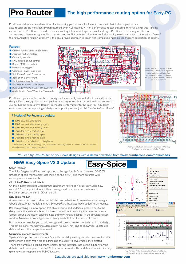
SSppeeeedd IInnccrreeaasseeThe Spice 'engine' itself has been updated to be significantly faster (between 50-150%simulation speed improvement depending on the circuit) and more accurate withconvergence improvements.
SSiimmuullaattiioonn IInntteerrffaaccee IImmpprroovveemmeennttssSignificantly improved simulator interface with the ability to drag and drop models into thelibrary, much better graph dialog editing and the ability to save graphs once plotted.There are numerous detailed improvements to the interface, such as the support for thedefinition of Fourier plots.The .PARAM can now be used in lib models and sub-circuits, Easy-spice now also supports the .FUNC function.
EEaassyy--SSppiiccee PPrroodduuccttA new Simulation menu makes the definition and selection of parameters easier using atabbed dialog. New models and new Symbols/Parts have also been added to this update.
Random probing is a new option that allows you to add additional probe types to thedesign once the initial simulation has been run.Without rerunning the simulator, you can'probe' around the design selecting nets and view instant feedback in the simulator graphwindow. Numerous probe types are instantly available from the shortcut menu.
Bias annotation enables you to add voltage and current markers to each net in the design.This can be done interactively, automatically (to every net) and to show/hide, update anddelete values in the design as required.
CCiirrccuuiittSSiimm9900 BBeenncchhmmaarrkk NNeettlliissttssOf the industry standard CircuitSim90 benchmark netlists (57 in all), Easy-Spice nowruns all 57 to the point at which they converge and produce an accurate result.No other product under £10K can do this!
New Random Probe function allows ‘probing’ within thedesign with results instantly displayed on the graph
Datasheets are available from www.numberone.com
For information on pricing contact:Number One Systems. Oak Lane, Bredon,
Further information on allproducts and prices available at:
www.numberone.comCopyright (C) WestDev Ltd 2005. All rights reserved. E&OE. All trademarks acknowledged to their rightful owners
You can get a full listing of parts from www.numberone.com/downloads/prolibrary .pdf
Over 14,500 library parts for Easy-PC
The Pro-Library contains over 14,500 Components, Symbols and Footprints ready-to-use in your design selectedfrom the following popular manufacturers parts lists - plus others!
Datasheets are available from www.numberone.com
The NEW optional IPC library contains over 950 supplementary surfacemount PCB footprint libraries for use with any variant of Easy-PC
The IPC PCB symbol library containssurface mount devices in a range ofpackage types.These include chipcapacitors, flat packs and chip carriers,in a range of sizes and pin counts, asdefined in the standard.The component library contains thesame number of items as the PCBsymbol library, with a one-to-onecorrespondence in naming to save youtime creating them.