100
Reference Manual 00809-0100-4889, Rev AA July 2018 Rosemount ™ Xi Advanced Electronics for Zirconium Oxide Flue Gas O2 Probes

Reference Manual00809-0100-4889, Rev AA
July 2018
Rosemount™ Xi
Advanced Electronics for Zirconium Oxide Flue Gas O2 Probes

Essential Instructions
Read this page before proceeding!
Emerson designs, manufactures, and tests its products to meet many national and international standards. Because theseinstruments are sophisticated technical products, you must properly install, use, and maintain them to ensure they continue tooperate within their normal specifications. The following instructions must be adhered to and integrated into your safety programwhen installing, using, and maintaining Emerson's Rosemount products. Failure to follow the proper instructions may cause any oneof the following situations to occur: loss of life, personal injury, property damage, damage to this instrument, and warrantyinvalidation.
• Read all instructions prior to installing, operating, and servicing the product.
• If you do not understand any of the instructions, contact your Emerson representative for clarification.
• Follow all warnings, cautions, and instructions marked on and supplied with the product.
• Inform and educate your personnel in the proper installation, operation, and maintenance of the product.
• Install your equipment as specified in the installation instructions of the appropriate instruction manual and per applicablelocal and national codes. Connect all products to the proper electrical and pressure sources.
• To ensure proper performance, use qualified personnel to install, operate, update, program, and maintain the product.
• When replacement parts are required, ensure that qualified people use replacement parts specified by Emerson.Unauthorized parts and procedures can affect the product's performance, place the safe operation of your process at risk,and VOID YOUR WARRANTY. Look-alike substitutions may result in fire, electrical hazards, or improper operation.
• Ensure that all equipment doors are closed and protective covers are in place, except when maintenance is being performedby qualified people, to prevent electrical shock and personal injury.
The information contained in this document is subject to change without notice.
NOTICEThe 375 Field Communicator must be upgraded to System Software 2.0 with Graphic License for operation with Xi Electronics. TheAMS software must be upgraded to AMS 8.0 or above.Contact Emerson's Global Service Center (GSC) at 1-800-833-8314 to upgrade the 375 Field Communicator software to SystemSoftware 2.0 with Graphic License.
Preface
The purpose of this manual is to provide information concerning the components,functions, installation, and maintenance of the Xi Electronics.
Some sections may describe equipment not used in your configuration. You should become thoroughly familiar with the operationof this module before operating it. Read this instruction manual completely.
Definitions
The following definitions apply to WARNINGS, CAUTIONS, and NOTICES found throughoutthis publication.
WARNING!Highlights an operation or maintenance procedure, condition, statement, etc. that if not strictly observed, could result in injury,death, or long-term health hazards of personnel.
CAUTION!Highlights an operation or maintenance procedure, practice, condition, statement, etc. that if not strictly observed, could result indamage to or destruction of equipment or loss of effectiveness.
NOTICEHighlights an essential operating procedure, condition, or statement.

Symbols
:Earth (ground) terminal
:Protective conduit or terminal
:Risk of electrical shock
:Warning: Refer to Instruction Manual
NOTICEThe number in the lower right corner of each illustration in this publication is a manual illustration number. It is not a part numberand is not related to the illustration in any technical manner.
Overview
The Xi is specifically designed to control a zirconium oxide probe for measuring oxygen,usually the O2 remaining from a combustion process. Call the Rosemount CustomerSupport Center (CSC) to get recommendations for other oxygen probes: 800 854 8257 (USand Canada).
The Xi electronics has several main functions:
1. Heater Control: The electronics receives a type K thermocouple input from an O2 probe and switches power on and off tothe probe's heater in order to maintain a temperature setpoint of 1357 °F (736 °C).
2. Signal Conditioning: The electronics receives the raw millivolt signal from the O2 sensing cell and then linearizes andamplifies the signal to provide a linear 4-20 mA output signal used for recording or as in input into a DCS system for controlpurposes.
3. Calibration: A bottled calibration gas of known value is typically flowed into the probe's sensor to verify that it is readingcorrectly. If the signal is out of calibration, the calibration gas is used to adjust the 4-20 mA output signal. During calibration,the Xi prompts the technician to flow two calibration gases into the probe and, with the calibration gases flowing,automatically adjusts the O2 signal. With the addition of a Single Probe Sequencer (SPS), the Xi electronics can also switchthe calibration gases on and off.
4. Diagnostics: Multiple alarms are available for display. The alarm displays are intended to assist a technician in locating wherean instrument problem may reside.
The electronics has been verified to operate the following probes:
• Westinghouse 218 and World Class
• Rosemount Oxymitter
• Yokogawa
Technical Support Hotline
For assistance with technical problems, please call the Customer Support Center (CSC).The CSC is staffed 24 hours a day, 7 days a week.
Phone: 1-800-433-6076, 1-440-914-1261
In addition to the CSC, you may also contact Field Watch. Field Watch coordinates Emerson's field service throughout the U.S. andabroad.
Phone: 1-800-654-RSMT (1-800-654-7768)
Emerson may also be reached via the Internet through email and the World Wide Web:
Email: [email protected]

World Wide Web: www.Emerson.com/RosemountGasAnalysis
Warranty
RosemountTM warrants that the equipment manufactured and sold by it will, uponshipment, be free of defects in workmanship or material. Should any failure to conform tothis warranty become apparent during a period of one year after the date of shipment,Rosemount shall, upon prompt written notice from the purchaser, correct suchnonconformity by repair or replacement, F.O.B. factory of the defective part or parts.Correction in the manner provided above shall constitute a fulfillment of all liabilities ofRosemount with respect to the quality of the equipment.
THE FOREGOING WARRANTY IS EXCLUSIVE AND IN LIEU OF ALL OTHER WARRANTIES OF QUALITY WHETHER WRITTEN, ORAL, ORIMPLIED (INCLUDING ANY WARRANTY OF MERCHANTABILITY OR FITNESS FOR PURPOSE).
The remedy(ies) provided above shall be purchase'rs sole remedy(ies) for any failure of Rosemount to comply with the warrantyprovisions, whether claims by the purchaser are based in contract or in tort (including negligence).
Rosemount does not warrant equipment against normal deterioration due to environment. Factors such as corrosive gases andsolid particulates can be detrimental and can create the need for repair or replacement as part of normal wear and tear during thewarranty period.
Equipment supplied by Rosemount but not manufactured by it will be subject to the same warranty as is extended to Rosemount bythe original manufacturer.
At the time of installation, it is important that the required services are supplied to the system and that the electronic controller isset up at least to the point where it is controlling the sensor heater. This will ensure that, should there be a delay betweeninstallation and full commissioning, the sensor being supplied with ac power and reference air will not be subjected to componentdeterioration.

Contents
Chapter 1 Description and specifications ........................................................................................11.1 Component checklist ...................................................................................................................11.2 System overview ..........................................................................................................................2
1.2.1 Scope ............................................................................................................................ 21.2.2 System configurations .................................................................................................. 31.2.3 Automatic calibration ....................................................................................................41.2.4 Communication options ............................................................................................... 4
1.3 Specifications .............................................................................................................................. 6
Chapter 2 Install .............................................................................................................................92.1 System considerations ...............................................................................................................102.2 Mechanical installation .............................................................................................................. 10
2.2.1 Mount ......................................................................................................................... 102.3 Electrical installation ..................................................................................................................13
2.3.1 Optional flame safety interlock ................................................................................... 162.3.2 Wire the traditional architecture cable connections .................................................... 17
Chapter 3 Configure .....................................................................................................................193.1 Verify installation .......................................................................................................................19
3.1.1 Xi configuration .......................................................................................................... 193.2 Set test gas values ......................................................................................................................20
3.2.1 Setting test gas values using Field Communicator .......................................................203.3 Alarm relay output configuration ...............................................................................................20
3.3.1 Configuring alarm relays with the Xi keypad/display ....................................................213.3.2 Configuring autocalibration with the Field Communicator .......................................... 21
3.4 Configure analog output ............................................................................................................223.4.1 Configuring the analog output with the Xi keypad/display .......................................... 223.4.2 Configuring alarm relays with the Field Communicator ............................................... 23
3.5 Autocalibration setup ................................................................................................................ 233.6 Optional advanced features inside the Xi ................................................................................... 23
3.6.1 Extended process temperature range to 1472 °F (800 °C) ............................................243.6.2 Stoichiometer ............................................................................................................. 243.6.3 Programmable reference ............................................................................................ 24
Chapter 4 Startup and operation .................................................................................................. 274.1 Overview ................................................................................................................................... 274.2 Startup ...................................................................................................................................... 27
4.2.1 Operation via Xi ...........................................................................................................284.2.2 Error conditions ...........................................................................................................284.2.3 Xi Controls .................................................................................................................. 284.2.4 Password protection ................................................................................................... 32
4.3 System parameter descriptions ................................................................................................. 334.4 Probe parameter descriptions ....................................................................................................364.5 Operation via HART/AMS ........................................................................................................... 41
4.5.1 Field communicator signal line connections ................................................................ 414.5.2 Field Communicator menu trees ................................................................................. 42
4.6 Offline and online operations .....................................................................................................444.7 Calibration - general .................................................................................................................. 45
Contents
Reference Manual i

4.8 O2 calibration ............................................................................................................................ 454.8.1 O2 calibration with Xi .................................................................................................. 464.8.2 O2 calibration with Xi and Field Communicator ........................................................... 47
4.9 D/A trim .....................................................................................................................................484.9.1 D/A trim with Xi ...........................................................................................................48
Chapter 5 Troubleshooting .......................................................................................................... 495.1 Overview of operating principles ............................................................................................... 495.2 General ......................................................................................................................................50
5.2.1 Grounding ...................................................................................................................505.2.2 Electrical noise ............................................................................................................ 505.2.3 Electrostatic discharge ................................................................................................ 51
5.3 Alarm indications .......................................................................................................................515.4 Identifying and correcting fault indications ................................................................................525.5 Calibration passes, but still reads incorrectly ..............................................................................54
5.5.1 Probe passes calibration, O2 still reads high .................................................................545.5.2 Probe passes calibration, O2 still reads low .................................................................. 555.5.3 How do I detect a plugged diffuser? ............................................................................ 555.5.4 Can I calibrate a badly plugged diffuser? ......................................................................55
Chapter 6 Maintenance and service ..............................................................................................576.1 Overview ................................................................................................................................... 576.2 Maintenance intervals ................................................................................................................576.3 Calibration ................................................................................................................................. 58
6.3.1 Automatic calibration ................................................................................................. 586.3.2 Manual calibration ...................................................................................................... 58
6.4 Replacement parts .....................................................................................................................586.5 Xi components replacement ......................................................................................................58
6.5.1 I/O board replacement ................................................................................................ 606.5.2 AC relay board replacement ........................................................................................ 646.5.3 Power supply board replacement ................................................................................ 656.5.4 Xi front panel replacement ..........................................................................................676.5.5 DR board replacement ................................................................................................ 69
Chapter 7 Replacement parts ....................................................................................................... 737.1 Xi electronics ............................................................................................................................. 737.2 Calibration components ............................................................................................................ 74
Chapter 8 Optional accessories .................................................................................................... 758.1 HART handheld 375/475 Field Communicator ...........................................................................758.2 Asset Management Solutions (AMS) .......................................................................................... 768.3 By-Pass Packages ....................................................................................................................... 768.4 Rosemount SPS 4001B Single Probe Autocalibration Sequencer ................................................ 778.5 Rosemount IMPS 4000 Intelligent Multiprobe Test Gas Sequencer ............................................ 788.6 O2 calibration gas ...................................................................................................................... 798.7 OxyBalance Display and Averaging System ................................................................................ 80
Appendices and referenceAppendix A XPS information ........................................................................................................... 81
A.1 XPS equipment description ........................................................................................................81A.1.1 Remote XPS for 44 V probes - 6A00358G01 ................................................................ 81A.1.2 Remote XPS for 115 V probes - 6A00358G03 .............................................................. 82
Contents
ii Xi

A.1.3 Integral XPS 6A00365G01 with Xi (for 44 V probes) .................................................... 83A.1.4 Other XPS uses ............................................................................................................ 83
A.2 Specifications ............................................................................................................................ 90A.3 Recommended spare parts ........................................................................................................ 90
Appendix B Service support ............................................................................................................ 91
Contents
Reference Manual iii

Contents
iv Xi
1 Description and specifications
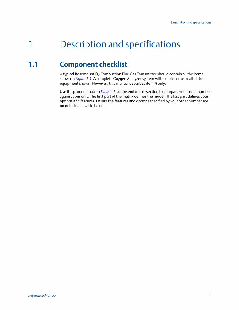
1.1 Component checklistA typical Rosemount O2 Combustion Flue Gas Transmitter should contain all the itemsshown in Figure 1-1. A complete Oxygen Analyzer system will include some or all of theequipment shown. However, this manual describes item H only.
Use the product matrix (Table 1-1) at the end of this section to compare your order numberagainst your unit. The first part of the matrix defines the model. The last part defines youroptions and features. Ensure the features and options specified by your order number areon or included with the unit.
Description and specifications
Reference Manual 1

Typical system packageFigure 1-1:
A. Quick Start GuideB. Weld plateC. Traditional architecture cableD. O2 probeE. Reference Air Set (not used if SPS 4001B or IMPS 4000 is used)F. HART® 375/475 Field Communicator package (optional)G. Optional SPS 4001B or IMPS 4000 Autocalibration SequencerH. Xi Advanced Electronics
1.2 System overview
1.2.1 ScopeThis Instruction Manual supplies details needed to install, start up, operate, and maintainthe Xi Electronics. Signal conditioning electronics output a 4-20 mA signal representingthe O2 value. This information, plus additional details, can be accessed with the HARTModel 375/475 Field Communicator or Asset Management Solutions (AMS) software..
Description and specifications
2 Xi
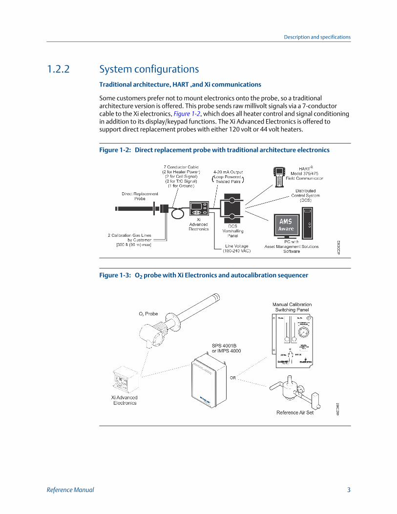
1.2.2 System configurationsTraditional architecture, HART ,and Xi communications
Some customers prefer not to mount electronics onto the probe, so a traditionalarchitecture version is offered. This probe sends raw millivolt signals via a 7-conductorcable to the Xi electronics, Figure 1-2, which does all heater control and signal conditioningin addition to its display/keypad functions. The Xi Advanced Electronics is offered tosupport direct replacement probes with either 120 volt or 44 volt heaters.
Direct replacement probe with traditional architecture electronicsFigure 1-2:
O2 probe with Xi Electronics and autocalibration sequencerFigure 1-3:
Description and specifications
Reference Manual 3

1.2.3 Automatic calibrationCalibrations consist of introducing bottled gases of known value into the probe so theelectronics can make automatic adjustments to the O2 readings to match the bottled gasvalue. 0.4% O2 and 8% O2 (balance nitrogen) gases are recommended. Never use nitrogenor instrument air as calibration gases.
Flowmeters (for calibration gases) and regulators and flowmeters (for reference air) areavailable as loose components, mounted into an optional manual calibration switchingpanel or as a fully automated calibration system, Figure 1-3, where calibration solenoids areswitched from the Xi Electronics. See IM-106-340AC, SPS 4000B Single ProbeAutocalibration Sequencer or IM-106-400IMPS, IMPS 4000 Intelligent Multiprobe Test GasSequencer, for additional details.
1.2.4 Communication options
Data communicationsAn operator can configure and troubleshoot the O2 probe system in one of two ways:
1. Using the Xi Advanced Electronics; the Xi carries the following optional advancedfeatures:
• Fully automatic calibration
• Flame safety interface
• High temperature operation [above 1292 °F (700 °C) standard temperature]
• Stoichiometer feature provides the ability to indicate O2 efficiency when thecombustion process goes into reducing conditions (0% O2).
• Programming reference provides advanced accuracy when measuring at or nearO2 level (20.95% O2).
2. Using the HART interface, the Xi's 4-20 mA output line transmits an analog signalproportional to the oxygen level. The HART output is superimposed on the 4-20 mAoutput line. This information can be accessed through the following:
• Rosemount 375/475 Field Communicator - The handheld communicatorrequires Device Description (DD) software specific to the Xi. The DD software willbe supplied with many 375/475 units, but can also be programmed into existingunits at most Emerson service offices. See Chapter 4 for additional information.
• Personal computer (PC) - The use of a personal computer requires AMS softwareavailable from Emerson.
• Delta V and Ovation Distributed Control System (DCS) with AMS-insidecapability.
NOTICEThe 375 Field Communicator must be upgraded to System Software 2.0 with GraphicLicense for operation with the Xi. The AMS software must be upgraded to AMS 8.0 orabove.Contact Emerson's Global Service Center (GSC) at 1-800-833-814 to upgrade the 375Field Communicator software to System Software 2.0 with Graphic License.
Description and specifications
4 Xi
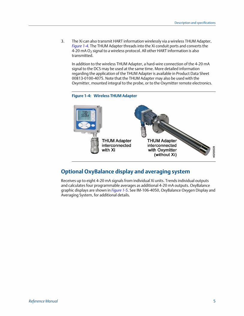
3. The Xi can also transmit HART information wirelessly via a wireless THUM Adapter, Figure 1-4. The THUM Adapter threads into the Xi conduit ports and converts the4-20 mA O2 signal to a wireless protocol. All other HART information is alsotransmitted.
In addition to the wireless THUM Adapter, a hard-wire connection of the 4-20 mAsignal to the DCS may be used at the same time. More detailed informationregarding the application of the THUM Adapter is available in Product Data Sheet00813-0100-4075. Note that the THUM Adapter may also be used with theOxymitter, mounted integral to the probe, or to the Oxymitter remote electronics.
Wireless THUM AdapterFigure 1-4:
Optional OxyBalance display and averaging system
Receives up to eight 4-20 mA signals from individual Xi units. Trends individual outputsand calculates four programmable averages as additional 4-20 mA outputs. OxyBalancegraphic displays are shown in Figure 1-5. See IM-106-4050, OxyBalance Oxygen Display andAveraging System, for additional details.
Description and specifications
Reference Manual 5

OxyBalance displaysFigure 1-5:
1.3 Specifications
SpecificationsTable 1-1:
Measurement specifications
Net O2 range 0 to 50% O2 user scalable
-2 to 50% O2 user scalable with stoichiometer
Lowest detectable limit 0.01% O2
Signal stability ±0.03% O2
Accuracy in reducing conditions ±10% of reading or 0.1% O2
System responses in reducing conditions Going from oxidizing to reducing -T90 in 120 seconds
Going from reducing to oxidizing -T90 in 30 seconds
Ambient temperature effect on Xi 4-20 mA signal Less than 0.0025% O2 per degree Celsius
Environmental specifications
Xi Advanced Electronics Type 4X/IP66 polycarbonate material
Ambient temperature limits -4 to 122 °F (-20 to 50 °C)
-4 to 158 °F (-20 to 70 °C) as measured by electronics
Xi LCD display: ambient temperature limits -4 to 131 °F (-20 to 55 °C)
Description and specifications
6 Xi

Specifications (continued)Table 1-1:
General purpose certifications
Installation specifications
Mounting Panel, wall, or pipe
Reference air 0.5 scfh (0.25 l/min), clean, dry, instrument-quality air(20.95% O2), regulated to 5 psi (34 kPa)
Calibration Semi-automatic or automatic
Cal gases 0.4% O2 and 8% O2, balance N2
Traditional architecture cable 200 ft (61 m) maximum length
Transmitter electrical power 12 - 24 Vdc (loop-powered from control room or Xi)
Electrical power for Xi 100 - 240 Vac ±10%, 50/60 Hz
Power consumption of Xi 12 VA maximum or 776 VA maximum with traditional arch-tecture, 120 V probes
450 VA maximum with traditional architecture, 44 Vprobes
Alarm relay outputs Two provided - 2 Amperes, 30 Vdc, Form-C
Optional loss of flame input Internally powered input to remove heater power actuatedvia dry contact output from user's flame scanner
Emerson has satisfied all obligations from the European leg-islation to harmonize the product requirements in Europe.All static performance characteristics are with operatingvariables constant. Specifications subject to change with-out notice.
Product matrix, Xi advanced electronicsTable 1-2:
Xi Xi Advanced Electronics
Code Remote type
01 Single channel(1)
02 Single channel, accepting a loss-of-flame input to remove heater power with flamestatus relay(1)
03 Dual channel(1)
04 Single channel traditional architecture for 120 V probes
05 Single channel traditional architecture for 44 V probes
Code Mounting
00 No hardware
01 Panel mount kit with gasket
02 2 in. pipe/wall mount kit
Description and specifications
Reference Manual 7

Product matrix, Xi advanced electronics (continued)Table 1-2:
Code Cable
00 No cable
10 20 ft (6 m) cable
11 40 ft (12 m) cable
12 60 ft (18 m cable)
13 80 ft (24 m cable)
14 100 ft (30 m) cable
15 150 ft (45 m) cable
16 200 ft (60 m) cable
Code Stoichiometer function
00 None
01 Single channel (stoichiometer cell also required in probe)
02 Dual channel (stoichiometer cell also required in probe)
Code Programmable reference function
00 None
01 Single channel
02 Dual channel
Code 800 deg C process function
00 None
01 Single channel
02 Dual channel
1. Requires XPS transmitter, P/N 6A00358G03
NoteAll static performance characteristics are with operating variables constant. Specifications subject tochange without notice.
Description and specifications
8 Xi

2 Install
WARNING!
Before installing this equipment, read Safety Instructions. Failure to follow safety instructionscould result in serious injury or death.
WARNING!
ELECTRICAL HAZARDInstall all protective equipment covers and safety ground leads after installation. Failure toinstall covers and ground leads could result in serious injury or death.
WARNING!
HAZARDOUS AREASThe Xi Advanced Electronics can be installed in general purpose areas only. Do not install the Xiin hazardous areas or in the vicinity of flammable liquids.
WARNING!
ELECTRICAL HAZARDIf external loop power is used, the power supply must be a safety extra low voltage (SELV)type.
NOTICE
All unused ports on the probe housing and Xi enclosure should be plugged with a suitablefilling.
Install
Reference Manual 9

2.1 System considerationsA typical system installation for an Xi or O2 probe is shown in Figure 2-1.
Typical system installationFigure 2-1:
A. GasesB. DuctC. Adapter plate and flangeD. Instrument air supply (reference air)E. Pressure regulatorF. FlowmeterG. Calibration gasH. Line voltageI. 4 to 20 mA signalJ. Rosemount 6888Xi Advanced Electronics (optional)K. Stack
2.2 Mechanical installation
2.2.1 MountThe Xi Advanced Electronics is available in a panel mounting, wall mounting, or pipemounting configuration.
Install
10 Xi
Refer to Figure 2-2 or Figure 2-3 for the panel, wall, or pipe mounting details.
Procedure
1. Ensure all components are available to install the Xi.
2. Select a mounting location near or removed from the O2 probe.
Consider the temperature limitations of the Xi (see Section 1.3) when selecting themounting location.
3. Mount the Xi at a height convenient for viewing and operating the interface.
Approximately 5 ft (1.5 m) is recommended.
4. The keypad window on the Xi may have interior and exterior protective membranes.Remove the protective membranes prior to use of the Xi enclosure.
NOTICEFailure to remove the protective membranes may cause the display to appear distorted.The membrane may be difficult or impossible to remove after extended use at elevatedtemperatures.
Install
Reference Manual 11

Xi Advanced Electronics - panel mounting detailsFigure 2-2:
Install
12 Xi
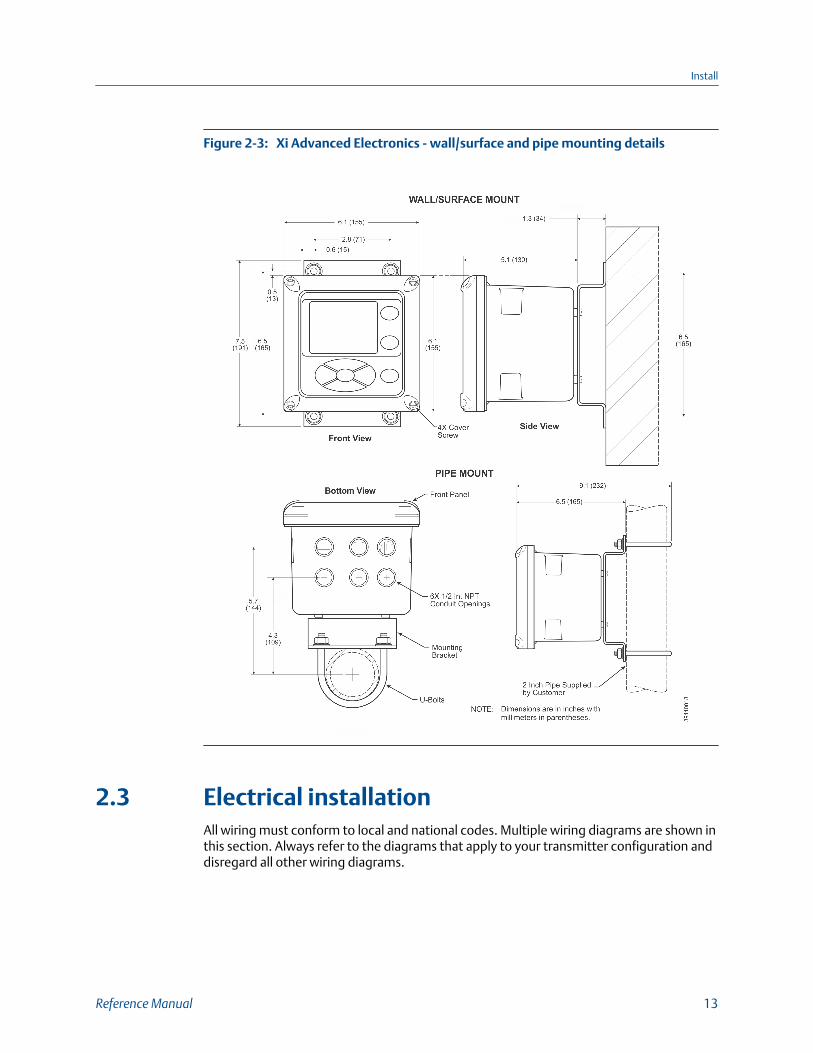
Xi Advanced Electronics - wall/surface and pipe mounting detailsFigure 2-3:
2.3 Electrical installationAll wiring must conform to local and national codes. Multiple wiring diagrams are shown inthis section. Always refer to the diagrams that apply to your transmitter configuration anddisregard all other wiring diagrams.
Install
Reference Manual 13

WARNING!
ELECTRIC SHOCKDisconnect and lock out power before connecting the power supply. Failure to lock out powercould result in serious injury or death.
WARNING!
ELECTRIC SHOCKInstall all protective covers and safety ground leads after installation. Failure to install coversand ground leads could result in serious injury or death.
WARNING!
ELECTRIC SHOCKTo meet the safety requirements of IEC 1010 (EC requirement) and ensure safe operation of thisequipment, connection to the main electrical power supply must be made through a circuitbreaker (min 10 A) which will disconnect all current-carrying conductors during a faultsituation. This circuit breaker should also include a mechanically operated isolating switch. If itdoes not, locate another external means of disconnecting the power supply close by. Circuitbreakers or switches must comply with a recognized standard such as IEC 947.
NoteLine, voltage, signal, and relay wiring must be rated for at least 105 °C (221 °F).
NOTICE
If a metal conduit is used with the Xi, the conduit should be reliably bonded to protective earth.The grounding plate inside the Xi is not bounded to PE and does not provide adequategrounding.
1. Remove cover screws from the front cover of the Xi. Swing down the front cover ofthe interface box.
2. Pull out the I/O board on the right-hand side of the card rack inside the Xi. If yoursystem is configured to operate two transmitter probes, there are two I/O interfaceboards.
3. See Figure 2-4. Connect the 4-20 mA signal wires at J4 of the I/O board. Attach thesupplied ferrite clamp over the 4-20 mA OUT wires that extend past the shield.
NOTICEInstallation of the ferrite clamp over the 4-20 mA OUT wires is required for compliancewith the European EMC directive.
Install
14 Xi
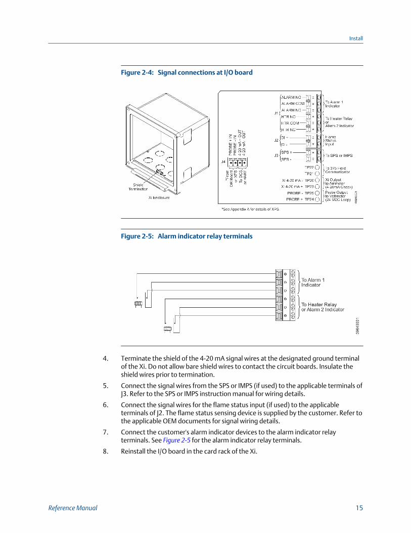
Signal connections at I/O boardFigure 2-4:
Alarm indicator relay terminalsFigure 2-5:
4. Terminate the shield of the 4-20 mA signal wires at the designated ground terminalof the Xi. Do not allow bare shield wires to contact the circuit boards. Insulate theshield wires prior to termination.
5. Connect the signal wires from the SPS or IMPS (if used) to the applicable terminals ofJ3. Refer to the SPS or IMPS instruction manual for wiring details.
6. Connect the signal wires for the flame status input (if used) to the applicableterminals of J2. The flame status sensing device is supplied by the customer. Refer tothe applicable OEM documents for signal wiring details.
7. Connect the customer's alarm indicator devices to the alarm indicator relayterminals. See Figure 2-5 for the alarm indicator relay terminals.
8. Reinstall the I/O board in the card rack of the Xi.
Install
Reference Manual 15

Power connections - Xi Advanced ElectronicsFigure 2-6:
9. If your system is configured for two channel operation, repeat steps 2 through 7 toconnect the other signal wires.
10. Remove the connector from the power supply board located on the left-hand side ofthe card rack inside the Xi.
11. See Figure 2-6. Connect the line, or L1, wire to the L1 terminal and the neutral, or L2,wire to the N terminal.
12. Reinstall the power supply connector in the power supply board.
13. Close and fasten the Xi cover.
2.3.1 Optional flame safety interlockA flame safety interlock by Emerson is available for the heater power disconnect wheneverthere is a loss of the process flame or a heater runaway condition (heater over-temperature) in the O2 probe. A simplified wiring diagram for the flame safety interlock isshown in Figure 2-7. The input is internally powered by the Xi and is actuated via a drycontact output from the user's flame scanner. A closed contact indicates a flame ispresent. An open contact indicates a loss of flame.
Install
16 Xi

Flame safety interlock - wiring diagramFigure 2-7:
2.3.2 Wire the traditional architecture cable connectionsA traditional architecture configuration is used to provide for remote location of thetransmitter electronics. All electronics are housed inside the Rosemount 6888Xi. A multi-conductor power/signal cable connects between the probe and the Rosemount 6888Xi.Use the following procedure to connect the traditional architecture probe to theRosemount 6888Xi.
NOTICE
The traditional architecture cable is provided at the specified length and is ready forinstallation. The cable glands must be properly terminated to maintain EMC/EMI noiseprotection.
Procedure
1. Run the 7-conductor cable between the traditional architecture probe and theinstallation site for the Rosemount 6888Xi. Use new cable conduit or trough asneeded.
2. Install the cable and lead wires to the probe per manufacturer's instructions.
3. Install the cable at the probe housing and at the Rosemount 6888Xi enclosureaccording to the following procedure:
a. Unscrew the locking nut from the gland assembly and slide the locking nut backalong the cable.
b. Pull the gland body away from the plastic insert.
Use care not to damage the cable shield braid.
Install
Reference Manual 17

c. Insert the cable wires into the proper entry port in either the probe housing orthe Rosemount 6888Xi enclosure.
d. At the probe housing, apply Teflon® tape or similar sealing compound to thetapered pipe threads. Thread the gland body into the probe housing untilproperly seated.
e. At the Rosemount 6888Xi enclosure, insert the gland body into the left frontcable port from the inside of the enclosure. Use the rubber O-ring provided toseal the cable port.
f. Ensure the cable shield braid is evenly formed over the gray insert.
When properly formed, the braid should be evenly spaced around thecircumference of the insert and not extend beyond the narrow diameter portion.
g. Carefully press the gray insert into the gland body. The grooves on the insertshould align with similar grooves inside the gland body. Press the insert in until itbottoms out in the gland body.
h. Slide the locking nut up and thread it onto the gland body. Tighten the lockingnut so the rubber grommet inside the plastic insert compresses against the cablewall to provide an environmental seal.
4. At the Rosemount 6888Xi, connect the cable leads to the connectors on thetransmitter I/O board.
Install
18 Xi

3 Configure
3.1 Verify installation
WARNING!
ELECTRIC SHOCKInstall all protective equipment covers and safety ground leads before equipment startup.Failure to install covers and ground leads could result in serious injury or death.
WARNING!
ELECTRIC SHOCKIf external loop power is used, the power supply must be a safety extra low voltage (SELV)type.
3.1.1 Xi configurationRefer to Figure 3-1 for the configuration of jumpers JP1 through JP8. The jumperconfiguration for your I/O board depends on the system design and system componentsused in your installation.
The setting of switch SW4 and the configuration of jumpers JP1 through JP8 must beverified on the I/O board in the Xi. All four dip switches on switch SW4 must be set to theOff position, as shown.
I/O board jumper configurationFigure 3-1:
Configure
Reference Manual 19

3.2 Set test gas valuesUse a Field Communicator or the Xi to set test gas values for calibration.An Xi shipped from the factory has test gas values for low and high set to 0.4% and 8%respectively. This same process must be performed any time a replacement transmitterboard, I/O board, or DR board is installed.
Setting test gas values using Xi display/keypad
Procedure
1. Press the MENU button once.
2. From the main menu, select PROBE 1.
3. From PROBE 1, select DETAILED SETUP.
4. From the DETAILED SETUP menu, select CAL SETUP.
5. From CAL SETUP, select Cal Gas 1. Enter the percent O2 used for the low O2 test gas.
6. From CAL SETUP, select Cal Gas 2. Enter the percent O2 used for the high O2 test gas.
7. Press the Left arrow key several times to return to the main menu.
8. Repeat steps 2 through 6 for PROBE 2 if configured for dual channel.
3.2.1 Setting test gas values using Field Communicator1. Use the Field Communicator software to access the HART menu.
2. From the DEVICE SETUP menu, select DETAILED SETUP.
3. From the DETAILED SETUP menu, select CAL SETUP.
4. From CAL SETUP, select Cal Gas 1. Enter the percent O2 used for the low O2 test gas.
5. From CAL SETUP, select Cal Gas 2. Enter the percent O2 used for the high O2 test gas.
3.3 Alarm relay output configurationThe Xi has two dry contact Form-C alarm relay output signals that can be configured ineight different modes through the Xi keypad display or the 375/475 Field Communicator.A list of possible configurations is shown in Table 3-1. Each alarm relay can be configuredseparately.
If the Xi is configured with the optional flame safety interlock, Alarm 2 is configured withHeater Relay and prewired to the AC relay board. In this condition, the relay configurationcannot be changed to any other setting. If the Xi is not configured with the optional flamesafety interlock, Heater Relay is not valid and cannot be chosen for Alarm 2.
Configure
20 Xi

Alarm relay output configurationsTable 3-1:
Mode Configuration
No alarm(1) The output is not configured for any alarm condition.
Unit alarm The output is configured for a unit alarm.
Low O2 alarm The output is configured for a low O2 alarm.
Low O2/unit alm The output is configured for a unit alarm and a low O2 alarm.
Cal recommended The output is configured for a calibration recommended display.
Cal rec/unit alm(2) The output is configured for a unit alarm and a calibration recom-mended display.
Low O2/cal rec The output is configured for a low O2 alarm and a calibration recom-mended display.
Low O2/unit/cal rec The output is configured for a low O2 alarm, a unit alarm, and a cali-bration recommended display.
Heater relay The output is configured for flame safety interlock.
(1) The default configuration for Alarm 2
(2) The default configuration for Alarm 1
3.3.1 Configuring alarm relays with the Xi keypad/display1. Press the MENU button once.
2. From the main menu, select PROBE 1.
3. From PROBE 1, select DETAILED SETUP.
4. From the DETAILED SETUP menu, select ALARM RELAY.
5. From ALARM RELAY, select as follows:
• Alm Relay1 - Alarm 1 mode
• Alm Relay2 - Alarm 2 mode
• Low O2 Alm SP - Low O2 alarm setpoint
• High Temp Alm SP - High temperature alarm setpoint
6. Press the Left arrow key several times to return to the main menu.
7. Repeat steps 2 through 6 for PROBE 2 if configured for dual channel.
3.3.2 Configuring autocalibration with the FieldCommunicator1. Use the 375/475 Field Communicator software to access the HART menu.
2. From the DEVICE SETUP menu, select DETAILED SETUP.
3. From the DETAILED SETUP menu, select CAL SETUP.
4. From CAL SETUP, select Auto Cal.
5. Press the Right arrow key to change the state from NO to YES.
Configure
Reference Manual 21

3.4 Configure analog outputThe analog output signal from the Rosemount 6888A can be configured for the 4-20 mArange and fault condition. A separate configuration is set up when the Rosemount 6888Ais used with the optional Rosemount 6888Xi Advanced Electronics. When the Rosemount6888A is used without the Rosemount 6888Xi, this parameter must be set to NO. If it is setto YES and a Rosemount 6888Xi is not connected, the Rosemount 6888A triggers an alarmand forces the analog output to the fault level. If the Rosemount 6888A is used later with aRosemount 6888Xi, the Rosemount 6888Xi automatically sets this parameter to YES.
An Rosemount 6888A shipped from the output has the analog outputs set to 4 to 20 mArange with a 3.5 mA alarm level. You must complete the same process any timetransmitter board is replaced.
1. Use the 375/475 Field Communicator to access the main HART menu.
2. From the main menu, select CONFIGURE.
3. From the CONFIGURE menu, select MANUAL SETUP.
4. From the MANUAL SETUP menu, select ANALOG OUTPUT.
5. From the ANALOG OUTPUT menu, select from the following parameters; then pressENTER.
• O2 LRV: O2 value at lower analog output value (0% at 4 mA, non-configurable)
• O2 URV: O2 value at upper analog output value (50% max at 20 mA)
• Output Range: Range of analog output (4-20 mA, non-configurable)
• Alarm level: O2 alarm level (3.5 mA or 21.1 mA)
• Xi Mode: Selects whether or not the Rosemount 6888A is used with a Rosemount6888Xi (should always be set to NO for a stand-alone Rosemount 6888A)
6. Use the stylus to enter the value; then press ENTER when finished.
7. Use the stylus to select SEND to update the Rosemount 6888A.
3.4.1 Configuring the analog output with the Xi keypad/display1. Press the MENU button once.
2. From the main menu, select PROBE 1.
3. From PROBE 1, select DETAILED SETUP.
4. From the DETAILED SETUP menu, select ANALOG OUTPUT.
5. From ANALOG OUTPUT, select the following parameters:
• O2 LRV - O2 value at the lower analog output value (0 mA or 4 mA)
• O2 URV - O2 value at the upper analog output value (20 mA)
• AO Range - Range of the analog output (0-20 mA or 4-20 mA)
• Signal Alarm Level - O2 alarm level (3.5 mA or 21.1 mA)
Configure
22 Xi
3.4.2 Configuring alarm relays with the Field Communicator1. Use the 375/475 Field Communicator software to access the HART menu.
2. From the DEVICE SETUP menu, select DETAILED SETUP.
3. From the DETAILED SETUP menu, select ALARM RELAY.
4. From ALARM RELAY, select as follows:
• Alm Relay1 - Alarm 1 mode
• Alm Relay2 - Alarm 2 mode
• Low O2 Alm SP - Low O2 alarm setpoint
• High Temp Alm SP - High temperature alarm setpoint
5. From CAL SETUP, select Cal Gas 2. Enter the percent O2 used for the high O2 test gas.
3.5 Autocalibration setupIf autocalibration is desired, the Xi must be used with either an SPS 4001B or IMPS 4000.The Xi must be properly configured before autocalibration can take place. Refer to theapplicable SPS 4001B or IMPS 4000 instruction manual for details on performingautocalibration. Refer to Chapter 4 for details on manual calibration procedures.
An Xi is shipped from the factory without autocalibration configured. This same processmust be performed any time a replacement I/O board is installed.
3.6 Optional advanced features inside the XiAdvanced features available inside the Xi are typically ordered as part of the initialpackage. However, these advanced features are also available for field retrofit.
An Xi is shipped from the factory with the optional enhanced software features enabledbased on the configuration.
WARNING!
The I/O board is shipped from the factory without any of the enhanced software featuresactivated. These features must be activated once the new board has been installed and beforethe remote interface is put into service.
WARNING!
If the existing I/O board has been operated with the stoichiometric enhanced software feature,this feature must be activated in the new board before the remote interface is put back intoservice. Failure to do so will cause a false analog output signal to the DCS.
Configure
Reference Manual 23
NOTICE
For enhanced software feature option upgrades or to enable the feature to duplicate theexisting configuration, contact Emerson at 1-800-433-6076. Reference the following:
• 6A00269G01: Enhanced software option upgrade, stoichiometric function
• 6A00269G02: Enhanced software option upgrade, programmable reference function
• 6A00269G03: Enhanced software option upgrade, 800 °C process function
3.6.1 Extended process temperature range to 1472 °F (800 °C)The Oxygen Analyzer employs a heater and thermacouple to maintain a temperaturesetpoint at 1357 °F (736 °C). Temperature control is maintained within ±1 °C to processtemperatures of about 1300 °F (705 °C). This is satisfactory for most applications, butexcursions to higher temperatures can occur in some processes. In these instances, theheater is turned off and the process temperature is used to heat the sensing cell.
The oxygen reading is adjusted immediately to compensate for the varying processtemperatures. Cell life will be reduced by continuous operation at temperatures above1300 °F (705 °C). If process temperatures are expected to be continuously above 1300 °F(705 °C), Emerson recommends the use of an optional bypass or probe mounting jacketaccessory. The extended temperature range feature is selected in the Xi product matrix,but may not be purchased as a field retrofit.
3.6.2 StoichiometerProcess upsets can sometimes cause a combustion process to go into sub-stoichiometricor reducing conditions. The oxygen readings from one or more probes may decline all theway to zero. The stoichiometer cell will measure the amount of oxygen deficiency duringthese reducing conditions. The trends in your DCS can be set up for a lower range limit of-1 or -2% oxygen to depict the level of oxygen deficiency.
You can see if your control recovery actions are having the desired effect. These types ofevents do not occur frequently, but knowing the parameters of the situation preventsover-correcting while coming out of the reducing condition. The stoichiometer featurerequires purchasing the acid resistant stoichiometer cell and the stoichiometer featureinside the Xi.
NOTICE
Make sure the DCS is configured for the same range as the Xi. For instance: -1% O2 to 10% O2.
3.6.3 Programmable referenceThe zirconium oxide sensing technology has historically measured process oxygen byusing ambient or instrument air as a reference (20.95% oxygen). The sensor develops mostof its signal at the low oxygen levels typically found in combustion flue gases (2 to 4%oxygen) and is most accurate at these levels. When measuring near 20.95% O2, the sensordevelops only a few millivolts of signal, and accuracy degrades.
Configure
24 Xi

The programmable reference feature permits you to use a bottled reference gas of lowoxygen value (0.4% oxygen recommended). When measuring at or near 21% oxygen, astrong negative oxygen signal results with much improved accuracy. A bottle of referencegas typically lasts about a month at the low flows required. Typical applications would be:
• Flue gas recirculation - controlling the mixing of flue gases into the burner windboxahead of the burner to reduce NOx emissions.
• Moisture monitoring - measuring the amount of moisture coming off of industrialdryers by noting that the dilution effect water vapor has on the normal 20.95%ambient drying air (non-combusion drying processes only).
• Enriched oxygen concentration - pure oxygen is sometimes mixed in with thecombustion air to increase heat at the flame. This is used in steel and other metalsreduction processes and in some catalyst regenerators.
Configure
Reference Manual 25

Configure
26 Xi

4 Startup and operation
4.1 OverviewInterface to the Xi for setup, calibration, and diagnostics can be via a 375/475 FieldCommunicator or Asset Management System.
Setup, calibration, and diagnostic operations differ depending on the selected interface forcommunications with the transmitter.
4.2 StartupThe O2 probe takes approximately 45 minutes to warm up to the 736 °C (1357 °F) heatersetpoint. The 4-20 mA signal remains at a default value of 3.5 mA through this warmupperiod. Once warm, the O2 reads oxygen, and the 4-20 mA signal's reading is based on thedefault range of 0-10% O2.
NOTICE
The Xi offers optional advanced features, such as elevated process temperature capability to1472 °F (800 °C), autocalibration via an SPS solenoid vox, a stoichiometer feature for indicatingthe level of oxygen defiency in reducing conditions, and programmable reference to enhanceaccuracy at near ambient levels of O2.
Startup and operation
Reference Manual 27

Xi display (typical)Figure 4-1:
4.2.1 Operation via XiThe following procedures describe operations using the Xi to set up and calibrate thesystem. Additional operating instructions are included in the SPS 4001B or IMPS 4000instruction manual, if applicable to your system.
4.2.2 Error conditionsIf there is an error condition at startup, an alarm message is displayed. Refer to Chapter 5 todetermine the cause of the error. Clear the error and cycle power. The %O2 andtemperature display should return without the alarm message.
4.2.3 Xi ControlsThe Xi can be used to change the software and alarm settings, to adjust the high and lowgas settings, and to initiate the calibration sequence. Refer to the following controldescriptions. Use the control keys on the front panel of the Xi (Figure 4-1) to navigate andedit the Xi menu (Figure 4-2).
• MENU toggles between three main menu options: System, Probe1, and Probe2 (ifavailable). The top level of the selected main menu is displayed.
• DIAG toggles between the Alarms list of the three main menus. All faults andwarnings related to the selected main menu device are displayed.
• ENTER saves newly entered data and returns you to the previous menu level.
Startup and operation
28 Xi
• EXIT returns you to the previous menu level without saving newly entered data.When navigating the menu tree, pressing EXIT returns you to the main menu.
• Up/Down keys scroll up and down through menu items. During data entry, the Up/Down keys increment and decrement the data values.
• Left arrow key returns you to the previous menu level. During data entry, the Leftarrow key moves the cursor one digit to the left.
• Right arrow key advances you to the next menu level and, when a menu item ishighlighted, selects the item from a list of menu options. During data entry, theRight arrow key moves the cursor one digit to the right.
Startup and operation
Reference Manual 29

Xi menuFigure 4-2:
Startup and operation
30 Xi

Startup and operation
Reference Manual 31

4.2.4 Password protectionBeginning with Xi system software version 1.05 or higher, the main display and diagnosticscreens of the Xi can be viewed at any time, but further access and unauthorizedconfiguration changes can be prevented by enabling a password protection feature.However, the Xi is shipped with password protection disabled.
Password protection can be enabled by selecting System Main Menu > Configure > LCD >Enable Password (see Figure 4-2).
Startup and operation
32 Xi

The factory default upon enabling the password protection is ROSE, but the password canconsist of any 4 alpha/numeric characters.
If you forget the password, call Rosemount technical support at 800-433-6076 to gainaccess to a master password.
A Lock icon is displayed at the top right corner of the main display when passwordprotection is in effect.
The password protection relocks itself after a certain number of seconds with no buttonpushes (defined as revert time in the same LCD setup menu). You can also force the frontpanel to be locked by selecting System Main Menu > Log Off. The Log Off selectionperforms on function if the password feature is disabled.
The Xi has a Reset function that reestablishes all factory default conditions, including thepassword protection feature, i.e., the password protection falls back to a disabledcondition after a reset.
4.3 System parameter descriptionsAmong the parameters available through the Xi and 375/475 Field Communicator menusare a number of system parameters. The system parameters define variables that configurethe Xi in the transmitter system. System parameters are described in the following table.
System parametersTable 4-1:
CPU Parameter name Units Parameter description
Y Version --- Software version number for the CPUboard
Y Build Num --- Software build number for the CPUboard
Y Comm Status --- Communication status between theCPU and I/O boards
Y Restart Cntr --- Software restarts counter for the CPUboard
N Pol Addr --- Polling address - address used to identi-fy a field device; changeable by user
N Serial Number --- I/O board serial number
N Features --- Available advanced software featuresfor the I/O board.
ON: feature supported.
OFF: feature not supported.
N EE Erase Count --- This is for nonvolatile memory diagnos-tic only.
Startup and operation
Reference Manual 33

System parameters (continued)Table 4-1:
CPU Parameter name Units Parameter description
Y Num Probe --- Number of probes configuration:
If set to 1, use One Probe configurationfor the main display.
If set to 2, use Two Probes configurationfor the main display.
Y Probe Sel --- This parameter is applicable only if theNum Probe configuration is set to 2. It de-fines which probe is to be displayed.
Y Probe 1 Enable --- Probe 1 state. If enabled, the probemenu will be displayed; otherwise it willnot be displayed. (No, Yes)
Y Probe 2 Enable --- Probe 2 state. If enabled, the probemenu will be displayed; otherwise it willnot be displayed (No,Yes)
Y LineX Probe --- Probe number for line x. (1, 2)
Y Line 1 Data --- Main display, line 1 data; 0 displays PV(O2), 1 displays SV (O2 temp)
Y Line 2 Data --- Main display, line 1 data; 0 displays PV(O2), 1 displays SV (O2 temp)
Y Line 3 DataL --- Main display, line 3 left hand side data:
0 displays PV (O2)
1 displays SV (O2 temp)
2 displays TV (cell imp)
3 displays 4 V (cell mV)
4 displays CJC temp
5 displays AO
6 displays OP mode
7 displays Tag
Y Line 3 DataR --- Main display, line 3 right hand side data
0 displays PV (O2)
1 displays SV (O2 temp)
2 displays TV (cell imp)
3 displays 4 V (cell mV)
4 displays CJC temp
5 displays AO
6 displays OP mode
7 displays Tag
Startup and operation
34 Xi

System parameters (continued)Table 4-1:
CPU Parameter name Units Parameter description
Y Line 4 DataL --- Main display, line 4 left hand side data
0 displays PV (O2)
1 displays SV (O2 temp)
2 displays TV (cell imp)
3 displays 4 V (cell mV)
4 displays CJC temp
5 displays AO
6 displays OP mode
7 displays Tag
Y Line 4 DataR --- Main display, line 4 right hand side data
0 displays PV (O2)
1 displays SV (O2 temp)
2 displays TV (cell imp)
3 displays 4 V (cell mV)
4 displays CJC temp
5 displays AO
6 displays OP mode
7 displays Tag
Y Revert time min Xi display reverts to main display time.Also locks screen if password protectionis enabled.
Y Language --- 0 displays English
1 displays Spanish
2 displays German
Y Contrast --- Display contrast (120 to 200)
Y Alarms --- See Chapter 5
Y Password --- Security password
Y Enable password --- Enables/disables security password pro-tection
Startup and operation
Reference Manual 35

4.4 Probe parameter descriptionsAmong the parameters available through the Xi and 375/475 Field Communicator menusare a number of Probe Parameters. The probe parameters define variables that configure aspecific probe in the transmitter system. Probe parameters are described in the followingtable:
Probe parametersTable 4-2:
TX I/O Parameter name Units Parameter description
Y Y O2 % Current oxygen concentra-tion value (O2%). The valueshould reflect the last goodO2 value if it is in the Lockstate during calibration.
Y Y O2 Temp ° C Current O2 sensor tempera-ture.
Y Y CJC Temp ° C Current cold junction tem-perature.
N Y Elec Temp ° C Current electronic tempera-ture measured at the I/Oboard.
Y Y O2 Cell mV Raw mV value for ZrO2 sen-sor.
N Y TC Volt mV O2 T/C voltage.
Y Y Cell Imp Ohm Cell impedance/sensor re-sistance measured.
Y Y Htr Volt Volt Heater voltage
Y Y CPU Volt Volt Transmitter CPU voltage.
Y Y O2 AO mA Analog output value repre-sents the O2 concentrationmeasurement.
N Y O2 AO% % O2 analog output percent-age for O2 AO
Y Y O2 Temp Max ° C This is the highest O2 sensortemperature reached sincelast reset.
Y Y CJC Temp Max ° C This is the highest tempera-ture reached at the coldjunction since last reset.
N Y Elec Temp Max ° C This is the highest tempera-ture reached at the I/O boardsince last reset.
Y Y Htr Volt Max ° C This is the highest heatervoltage reached since last re-set.
Startup and operation
36 Xi

Probe parameters (continued)Table 4-2:
TX I/O Parameter name Units Parameter description
Y Y Htr Duty Cycle --- O2 heater duty cycle. Valuebetween 0 and 1.
Y Y PID SP ° C PID temperature set point.
Y Y Htr Ramp Rate ° C/s Heater ramp rate calculatedin degree C per second.
N Y Flame Stat In --- Flame input state. (OFF/ON)
N Y SPS/IMPS In --- SPS/IMPS input state. (OFF/ON)
N Y SPS/IMPS out --- SPS/IMPS output state. (OFF/ON)
N Y Alm Relay 1 Out --- Alarm Relay 1 output state.
N Y Alarm Relay 2 Out --- Alarm Relay 2 output state.(OFF/ON)
Y Y OP Mode --- Device operating mode: PO= Power up; WU = Warm up(analog output is railed); NM= Normal operation; CA =Calibrating (analog outputcan be tracking or locked atlast good value based on AOTracks configuration; AL =Alarm detected (recovera-ble); SF=Alarm detected(non-recoverable)
Y Y Tag --- Device tag
Y Y Device ID --- Unique device ID number(HART)
Y Y PV is --- Primary variable assignment(HART)
Y Y SY is --- Secondary variable assign-ment (HART)
Y Y TY is --- Third variable assignment(HART)
Y Y QV is --- Fourth variable assignment(HART)
Y Y Cal Slope mV/Dec Current calibration slope.This is the slope value thatwas calculated as a result ofthe last successful calibra-tion.
Startup and operation
Reference Manual 37

Probe parameters (continued)Table 4-2:
TX I/O Parameter name Units Parameter description
Y Y Cal Const mV Current calibration constant.This is the constant valuethat was calculated as a re-sult of the last successful cal-ibration.
Y Y Cal Imp Ohm Cell impedance. This is thesensor resistance that wascalculated as a result of thelast successful calibration.
N Y Prev Slope mv/Dec Previous calibration slope.There are ten calibration re-sults. 1 is the most recent,and 10 is the least recent cal-ibration slope.
N Y Prev Const mV Previous calibration con-stant. There are ten calibra-tion results. 1 is the most re-cent, and 10 is the least re-cent calibration constant.
N Y Prev Cal Imp Ohm Previous cell impedance.This is the sensor resistancethat was calculated as a re-sult of the previous success-ful calibration. There are tencalibration results. Index 1 isthe most recent, and Index10 is the least recent sensorresistance measured.
N Y Failed Slope mV/Dec Failed calibration slope.
N Y Failed Const mV Failed calibration constant.
Y Y Cal Result mV Calibration result.
N Y Delta Imp --- Delta impedance since lastcalibration.
N Y Cal Step --- This represents the step thecalibration cycle is in.
N Y Time remain sec Time remaining in thepresent calibration cyclestate.
Y Y O2 slope mV/Dec O2 slope. This is the slopevalue that will be used to cal-culate O2.
Y Y O2 Const mV O2 constant. This is the con-stant value that will be usedto calculate O2.
Startup and operation
38 Xi

Probe parameters (continued)Table 4-2:
TX I/O Parameter name Units Parameter description
N Y T90 filter sec Analog output T90 time. Itrepresents the time to take astep change in oxygen toreach 90% of the final valueat the filter output.
N Y O2 Cell Ref % O2 sensor reference gas per-centage. It allows a sensorreference gas other than air.
N Y O2 Temp SP deg C O2 sensor set point. It allowsmeasurement of oxygenwith an elevated sensor tem-perature. (0 =736 deg C setpoint; 1 = 834 deg C setpoint)
N Y Features --- Advanced software features(0=Stoichiometer; 1=Pro-grammable Reference;2=Elevated Temperature)
Y Y O2 URV % Primary variable (O2%) upperrange value
Y Y O2 LRV % Primary variable (O2% lowerrange value)
N Y O2 AO Range --- Analog output polarity. (0 =4-20 mA; 1 = 20-4 mA)
Y Y O2 Alarm Level --- O2 alarm level. (0 = 3.5 mA; 1= 21.1 mA)
N Y Alarm Relay 1 --- Alarm Relay 1 mode. (noalarm; unit alarm; low O2
alarm; low O2/unit alarm; Calrecommended; Cal recom-mended/unit alarm; low O2/Cal recommended, low O2/unit alarm/Cal recommen-ded.)
N Y Alarm Relay 2 --- Alarm Relay 2 mode. (noalarm; unit alarm; low O2
alarm; low O2/unit alarm; Calrecommended; Cal recom-mended/unit alarm; low O2/Cal recommended, low O2/unit alarm/Cal recommen-ded; Heater relay)
N Y Low O2 Alm % Low O2 alarm threshold.
Startup and operation
Reference Manual 39

Probe parameters (continued)Table 4-2:
TX I/O Parameter name Units Parameter description
N Y Hi Temp Alm % High temperature alarmthreshold.
N Y AO Tracks --- Analog output track O2 sen-sor measurement during acalibration. (No, Yes)
N Y Auto Cal --- Enable/disable automaticcalibration.
No = Set to manual calibra-tion mode.
Yes = Set to automatic cali-bration mode.
N Y Start On CalRec --- Start automatic calibrationon Cal Recommended state.(No, Yes)
Y Y Cal Gas 1 % Test Gas 1 value. This is theactual value of the gas beingapplied during the Test Gas 1phase of a calibration.
Y Y Cal gas 2 % Test Gas 2 value. This is theactual value of the gas beingapplied during the Test Gas 2phase of a calibration.
Y Y Gas Time sec Test Gas application time.This is the length of time testgases are applied to the O2
probe during low or highTest Gas phase of a calibra-tion.
Y Y Purge Time sec Test Gas purge time. This isthe length of time before theoutput will be returned tothe process reading after acalculation.
N Y Cal Interval hr Automatic calibration inter-val. The number 9999 disa-bles the automatic timedcalibration.
N Y Next Cal Time hr Automatic calibration inter-val. The number 9999 disa-bles the automatic timedcalibration.
Y Y T EE Val --- Transmitter board nonvola-tile memory diagnostic
Startup and operation
40 Xi

Probe parameters (continued)Table 4-2:
TX I/O Parameter name Units Parameter description
N Y IO EE Val --- I/O board nonvolatile memo-ry diagnostic
Y Y Version --- Software version number forthe transmitter.
N Y Version --- Software version number forthe I/O board.
Y Y T Restart Cntr --- Software restarts count forthe transmitter.
N Y IO Restart Cntr --- Software restarts count forthe I/O board.
Y Y Alarms --- Current alarms (see Chapter 5).
4.5 Operation via HART/AMSThe 375/475 Field Communicator is a handheld communications interface device. Itprovides a common communications link to all microprocessor-based instruments that areHART compatible. The handheld communicator contains a liquid crystal display (LCD) and21 keys. A pocket-sized manual, included with the 375/475 Field Communicator, detailsthe specific functions of all the keys.
The 375/475 Field Communicator accomplishes its task using a frequency shift keying(FSK) technique. With the use of FSK, high-frequency digital communications signals aresuperimposed on the Xi's 4-20 mA current loop. The 375/475 Field Communicator doesnot disturb the 4-20 mA signal, as no net energy is added to the loop.
NOTICE
The 375 Field Communicator must be upgraded to System Software 2.0 with Graphic Licensefor operation with the Xi. The AMS software must be upgraded to AMS 8.0 or above foroperation with the Xi.Contact Emerson's Global Service Center (GSC) at 1-800-833-8314 to upgrade the 375 FieldCommunicator software to System Software 2.0 with Graphic License.
4.5.1 Field communicator signal line connectionsWhen working at the Xi, the 375/475 Field Communicator can be connected directly totest points TP21 and TP22 on the Xi I/O board as shown in Figure 4-3. The AM+ and AM-test points are provided to monitor the 4-20 mA signal without breaking into the loop.
Startup and operation
Reference Manual 41

375/475 Field Communicator connection at the XiFigure 4-3:
4.5.2 Field Communicator menu treesConnect the 375/475 Field Communicator in the Xi (Xi-to-DCS) 4-20 mA signal loop or tothe Xi terminals shown in Figure 4-3 and refer to Figure 4-4 for the 375/475 FieldCommunicator Xi menu tree.
Startup and operation
42 Xi

375/475 Field Communicator Xi menu treeFigure 4-4:
Startup and operation
Reference Manual 43

4.6 Offline and online operationsThe 375/475 Field Communicator can be operated both offline and online.
Startup and operation
44 Xi

Offline operations are those in which the communicator is not connected to the O2 probe.Offline operations include interfacing the 375/475 Field Communicator with a PC (refer toapplicable HART documentation regarding HART/PC applications).
In the online mode, the 375/475 Field Communicator is connected to the 4-20 mA analogoutput signal line. The communicator is connected in parallel to the O2 probe or in parallelto the 250 ohm load resistor.
4.7 Calibration - generalNew O2 cells may operate for more than a year without requiring calibration, but oldercells may require recalibration every few weeks as they near the end of their life.
A CALIBRATION RECOMMENDED alarm provides notice of when a calculation is required. Thisstrategy ensures that the O2 reading is always accurate and eliminates many unnecessarycalibrations based on calendar days or weeks since previous calibration.
The O2 probe(s) can be calibrated manually through the handheld 375/475 FieldCommunicator or the Xi. Fully automatic calibration can be performed automatically usingthe Xi and the SPS 4001B Single Probe Autocalibration Sequencer or the IMPS 4000Intelligent Multiprobe Sequencer.
4.8 O2 calibrationThis section covers manual calibration. For automatic calibration details, see theInstruction Manual for the SPS 4001B Single Probe Autocalibration Sequencer or the IMPS4000 Intelligent Multiprobe Test Gas Sequencer.
Calibration can be performed using three basic calibration methods. The methodsavailable to you for use depend on the configuration of your system. The sections thatfollow describe how to perform a calibration for two basic system configurations shown in Figure 4-5.
Included in the calibration procedures are instructions for setting up the calibrationparameters. Setup of the calibration parameters should be performed before the first O2calibration. Thereafter, perform calibration setup only as needed to change the calibrationparameters or to reset the parameters following the replacement of primary systemcomponents.
Before calibrating, verify that the configuration gas parameters are correct. Refer to Chapter 3.
Startup and operation
Reference Manual 45

Calibration methods, simplifiedFigure 4-5:
4.8.1 O2 calibration with XiFor systems with configuration 1, shown in Figure 4-5, use the following procedure toperform a calibration using the Xi. If necessary, use the Xi menu tree in Figure 4-2 forreference.
NOTICE
To select a menu item, use the up and down arrow keys to scroll to the menu item and pressthe right arrow key to select the menu item. To return to a preceding menu, press the leftarrow key.
Procedure
1. From the Main Menu, select SYSTEM to access the Xi System menu.
2. From the Xi SYSTEM menu, scroll down and select DETAILED SETUP.
3. Select menu item 4, CAL SETUP, to input the cal gas and flow times.
4. Return to the SYSTEM menu and select the last menu item, CALIBRATION, to accessthe CALIBRATION menu.
5. From the O2 CALIBRATION options, select Start Cal to start the O2 calibrationprocedure.
Startup and operation
46 Xi

WARNING!Failure to remove the Xi from automatic control loops prior to performing thisprocedure may result in a dangerous operating condition.
In the first Start Cal screen, a "Loop should be removed from automatic control"warning appears.
6. Remove the Xi from any automatic control loops to avoid a potentially dangerousoperating condition and press OK.
7. Follow the Xi display prompts to perform the O2 cal procedure.
4.8.2 O2 calibration with Xi and Field CommunicatorFor systems with configuration 2, shown in Figure 4-5, use the following procedure toperform a calibration of the system using the 375/475 Field Communicator. If necessary,use the menu tree in Figure 4-2 for reference.
NOTICE
To select a menu item, use the up and down arrow keys to scroll to the menu item and pressthe right arrow key to select the menu item. To return to a preceding menu, press the leftarrow key.
Procedure
1. Select DEVICE SETUP.
2. From the DEVICE SETUP screen, select menu item 4, DETAILED SETUP.
3. Select menu item 3, CAL SETUP, to input the cal gas and gas flow times.
4. Return to the DEVICE SETUP screen and select menu item 2, DIAG/SERVICE.
5. From the DIAG/SERVICE screen, select menu item 3, CALIBRATION, to access the O2CALIBRATION screen.
6. From the O2 CALIBRATION screen, select menu item 1, O2 CAL, to access the O2calibration procedure.
WARNING!Failure to remove the Xi from automatic control loops prior to performing thisprocedure may result in a dangerous operating condition.
In the first O2 CAL screen, a "Loop should be removed from automatic control"warning appears.
7. Remove the Xi from any automatic control loop to avoid a potentially dangerousoperating condition and press OK.
8. Follow the handheld 375/475 Field Communicator display prompts to perform theO2 cal procedure.
Startup and operation
Reference Manual 47

4.9 D/A trimThe D/A trim procedure is used to calibrate the 4-20 mA output signal to a precision mAmeasurement device.
The procedure that follow describe how to perform a D/A trim for the basic systemconfiguration shown in Figure 4-6. Only the signal to the DCS needs to be trimmed.
D/A trim methods, simplifiedFigure 4-6:
4.9.1 D/A trim with XiFor systems with configuration 1, shown in Figure 4-6, use the handheld 375/475 FieldCommunicator to access the D/A trim procedure according to the instructions that follow.Refer to the 375/475 Field Communicator Xi menu tree in Figure 4-2.
Procedure
1. From the DEVICE SETUP screen, select menu item 2, DIAG/SERVICE, to access thediagnostics and service menu options.
2. Select menu item 3, CALIBRATION, to access the calibration menu options.
3. Select menu item 3, 4-20 mA SIG, to access the 4-20 mA SIGNAL screen.
4. Select menu item 1, D/A TRIM, to start the trim procedure.
Startup and operation
48 Xi

5 Troubleshooting
5.1 Overview of operating principlesWhen the Zirconium Oxide sensing cell is heated to its setpoint [1357 °F (736 °C)], the cellgenerates a voltage that represents the difference between the process O2% and thereference O2% inside the probe (20.95% O2 instrument air).
When flowing calibration gases, the raw cell millivolt value should represent the levels onthe chart in Figure 5-1. Note that the raw cell millivolt value increases logarithmically as theO2 concentration decreases.
O2 sensor mV reading vs %O2 at 1357 °F (736 °C) (Reference air,20.95% O2)
Figure 5-1:
O2% EMF (mV)
100 -34
20 1.0
15 7.25
10 16.1
9 18.4
Troubleshooting
Reference Manual 49

O2% EMF (mV)
8 21.1
7 23.8
6 27.2
5 31.2
4 36.0
3 42.3
2 51.1
1 66.1
0.8 71.0
0.6 77.5
0.5 81.5
0.4 86.3
0.2 101.4
0.1 116.6
0.01 166.8
5.2 General
WARNING!
ELECTRIC SHOCKInstall all protective equipment covers and ground leads after troubleshooting. Failure toinstall covers and ground leads could result in serious injury or death.
Consider the following equipment conditions, features, and requirements whentroubleshooting a problem.
5.2.1 GroundingIt is essential that adequate grounding precautions are taken when installing the system.Thoroughly check both the probe and electronics to ensure the grounding quality has notdegraded during fault finding. The system provides facilities for 100% effective groundingand the total elimination of ground loops.
5.2.2 Electrical noiseThe Xi has been designed to operate in the type of environment normally found in a boilerroom or control room. Noise suppression circuits are employed on all field terminationsand main inputs. When fault finding, evaluate the electrical noise being generated in theimmediate circuitry of a faulty system. Ensure all cable shields are connected to earth.
Troubleshooting
50 Xi

5.2.3 Electrostatic dischargeElectrostatic discharge can damage the ICs used in the electronics. Before removing orhandling the circuit boards, ensure you are at ground potential.
5.3 Alarm indicationsThe first indication of a problem at the O2 measuring system usually comes from theoperators running the process. Critical alarms that render the O2 measurement unusablewill force the 4-20 mA analog output signal representing O2 to go to a default condition, asfollows:
4-20 mA signal alarm level Transmitter condition
0 mA Transmitter unpowered or completely failed
3.5 mA Critical alarm - transmitter reading unusable (factory de-fault)
3.8 mA Reading under range (Example - you set range to 2-10%.Current reading is 1.9%.)
4 to 20 mA Normal operation
20.5 mA Reading over range (Example - range is 0-10%. Currentreading is 12%.)
>21 mA Critical alarm - transmitter reading is unusable (you canchoose this alarm level instead of the factory default levelof 3.5 to 3.6 mA).
NOTICE
To ensure correct operation, you should make sure that the Digital Control System isconfigured to interpret these signal levels correctly.
Once an alarm condition is identified, the Rosemount 910Xi offers a number of diagnosticsto interprest the specific alarm.
Alarm indications are available via the optional Rosemount 6888Xi or the 375/475 FieldCommunicator and Rosemount's Asset Management software. When the error iscorrected and/or power is cycled, the diagnostic alarms will clear or the next error on thepriority list will appear.
Troubleshooting
Reference Manual 51
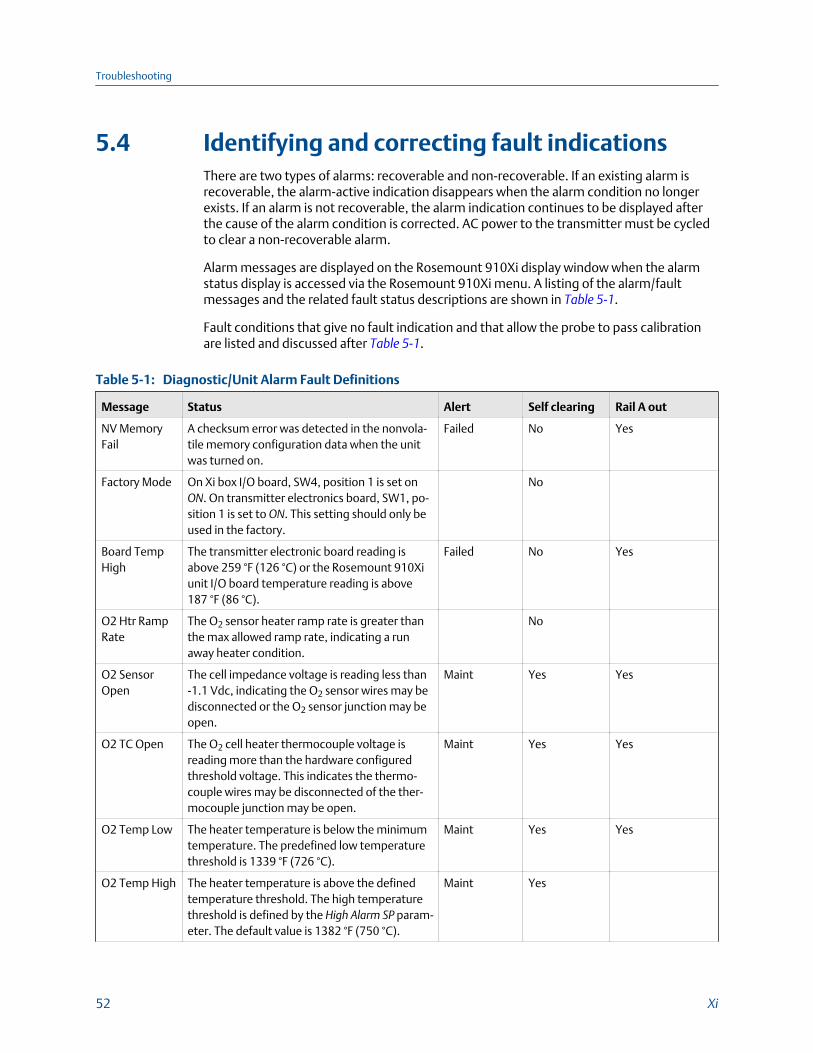
5.4 Identifying and correcting fault indicationsThere are two types of alarms: recoverable and non-recoverable. If an existing alarm isrecoverable, the alarm-active indication disappears when the alarm condition no longerexists. If an alarm is not recoverable, the alarm indication continues to be displayed afterthe cause of the alarm condition is corrected. AC power to the transmitter must be cycledto clear a non-recoverable alarm.
Alarm messages are displayed on the Rosemount 910Xi display window when the alarmstatus display is accessed via the Rosemount 910Xi menu. A listing of the alarm/faultmessages and the related fault status descriptions are shown in Table 5-1.
Fault conditions that give no fault indication and that allow the probe to pass calibrationare listed and discussed after Table 5-1.
Diagnostic/Unit Alarm Fault DefinitionsTable 5-1:
Message Status Alert Self clearing Rail A out
NV MemoryFail
A checksum error was detected in the nonvola-tile memory configuration data when the unitwas turned on.
Failed No Yes
Factory Mode On Xi box I/O board, SW4, position 1 is set onON. On transmitter electronics board, SW1, po-sition 1 is set to ON. This setting should only beused in the factory.
No
Board TempHigh
The transmitter electronic board reading isabove 259 °F (126 °C) or the Rosemount 910Xiunit I/O board temperature reading is above187 °F (86 °C).
Failed No Yes
O2 Htr RampRate
The O2 sensor heater ramp rate is greater thanthe max allowed ramp rate, indicating a runaway heater condition.
No
O2 SensorOpen
The cell impedance voltage is reading less than-1.1 Vdc, indicating the O2 sensor wires may bedisconnected or the O2 sensor junction may beopen.
Maint Yes Yes
O2 TC Open The O2 cell heater thermocouple voltage isreading more than the hardware configuredthreshold voltage. This indicates the thermo-couple wires may be disconnected of the ther-mocouple junction may be open.
Maint Yes Yes
O2 Temp Low The heater temperature is below the minimumtemperature. The predefined low temperaturethreshold is 1339 °F (726 °C).
Maint Yes Yes
O2 Temp High The heater temperature is above the definedtemperature threshold. The high temperaturethreshold is defined by the High Alarm SP param-eter. The default value is 1382 °F (750 °C).
Maint Yes
Troubleshooting
52 Xi

Diagnostic/Unit Alarm Fault Definitions (continued)Table 5-1:
Message Status Alert Self clearing Rail A out
O2 T/C Shor-ted
The O2 sensor heater temperature thermocou-ple voltage is shorted.
Maint Yes Yes
O2 T/C Re-versed
The O2 sensor heater temperature thermocou-ple voltage is reading a negative voltage, indi-cating the thermocouple wire connections maybe reversed.
Maint Yes Yes
O2 Htr Failure The O2 sensor heater temperature is not re-sponding to the controller and can't reach finaltemperature set by the device, indicating the O2
heater may have failed.
Yes
No Flame The Flame Status Relay Input is set to the OFFstate, indicating that it is not safe to operate theO2 heater and the heater should be turned off.
Yes
Xmtr Discon-nect
Communication failures detected betweentransmitter and the I/O board, indicating thetransmitter has been disconnected from the I/Oboard.
Yes
Cal Recom-mended
Probe calibration is recommended. The cell im-pedance is above 100 ohms and has shifted 50ohms since the last calibration; the accuracy ofthe O2 reading may be compromised.
Yes
Cal Failed A calibration error occurred during the last cali-bration. The measured slope or constant is out-side the acceptable range. (Slope: 34.5 to 57.5mv/decade) (Constant ±20 mv)
Maint Yes No
Cell Imp High The O2 sensor impedance/cell resistance valuemeasurement is greater than 2000 Ohms, indi-cating the cell may be beyond its useful life.
Maint Yes No
CPU VoltageLow
The CPU voltage is less than 2.7 V, indicatingthe CPU voltage is too low.
Yes
CPU VoltageHigh
The CPU voltage is more than 3.3 V, indicatingthe CPU voltage is too high.
Yes
Htr VoltageLow
The heater voltage for the O2 cell heater is be-low 35 volts.
Adv Yes No
Htr VoltageHigh
The heater voltage for the O2 cell heater isabove 264 volts.
Yes
Low O2 The O2 reading is below the Low O2 Alm SP. Yes
Troubleshooting
Reference Manual 53

5.5 Calibration passes, but still reads incorrectlyThere are a few fault conditions where no alarm indication is present and the probe passescalibration, but the O2 reading may still be incorrect.
An incorrect flow rate of calibration gases can cause a shifted calibration. If the flow rate ofcalibration gases is too low, process gases can mix in with the calibration gases, causing amixture at the cell that is different from what is noted on the calibration gas bottles.Always set the calibration flow rate when a new diffuser is installed and never readjust thisflow rate until another new diffuser is installed. For applications with heavy particulateloading, see Section 5.5.2.
If reference air is not supplied or is improperly supplied, the calibration may readincorrectly.
5.5.1 Probe passes calibration, O2 still reads high
External reference air leakThere may be a leak that is permitting ambient air to mix with the process gases. Sincemany combustion processes are slightly negative in pressure, ambient air can be drawninto the cell area, biasing the O2 reading upward.
1. Make sure that the calibration gas is capped tightly between calibrations.
2. If autocal is used, make sure the check valve is sealing properly.
Probe Leakage PathsFigure 5-2:
Internal reference air leakSee Figure 5-2. There may be a leak inside the O2 probe itself, permitting the reference air(20.95% O2) to mix with the process gases at the cell. To confirm this leak condition,pressurize the inside (reference side) of the probe by plugging the reference air exhaust
Troubleshooting
54 Xi

port with your finger for one minute. (The conduit ports where the signal and power wirespass may also need to be sealed.) The O2 reading should decrease slightly. If the O2reading increases during this test, there is a leak inside the probe.
1. Acid condensation inside the probe can degrade the hose that carries the cal gas tothe cell. Inspect this hose. Dislodging or improper installation of the cal gas orreference air hose can cause a leakage path.
2. The sensing cell is fastened to the end of the probe tube and uses a corrugatedwasher to separate the process gases from the ambient reference air. Thecorrugated washer may be damaged by corrosion. Discard used washer.
NOTICE
Always install a new corrugated washer whenever you remove the sensing cell from the probe.
5.5.2 Probe passes calibration, O2 still reads lowThe diffusion element at the end of the probe is a passive filter. It plugs very slowly,because there is no active flow being drawn across it. In applications that have a heavyparticulate loading (coal or wood fired boilers, cement and lime kilns, catalystregeneration, recovery boilers, etc.) this diffusion element will eventually plug.
NOTICE
It is important not to pressurize the sensing cell during calibrations by flowing excessive calgas against a plugged diffuser. Always use a two-stage regulator for setting calibration gaspressure. Calibration flow rates should be set only when a new diffuser is installed. As thediffuser plugs, do not adjust the flow rates upward.
5.5.3 How do I detect a plugged diffuser?The O2 cell's speed of response will degrade. The O2 trend in the control room will becomesmoother.
When calibrating, the calibration gas flow rate will be noted to be lower. Never readjustthis flow upwards to correct for a plugged diffuser. Adjust this flow only when a newdiffuser is installed.
Always note the time it takes for the cell to recover to the normal process value after thecal gas is removed. As the diffuser plugs, this recovery time will get longer and longer. Usea calibration record to record and track calibration response times.
5.5.4 Can I calibrate a badly plugged diffuser?It may not be possible to immediately replace a plugged diffuser while the process is on-line.
Troubleshooting
Reference Manual 55

You can calibrate the probe without pressurizing the cell by adjusting the calibration gasflow rate downward before calibration. For instance, say the process is at 3%, and the firstcalibration gas is 8%. Adjust the flow of cal gas downward until the reading begins tomigrate from 8% to lower values, indicating that the process gases are now mixing with thecalibration gases.
Adjust the flow rate back up until this mixing is just eliminated. Calibrate at this flow rate.Replace the diffuser at the first opportunity.
WARNING!
ELECTRIC SHOCKInstall all protective equipment covers and safety ground leads after troubleshooting. Failureto install covers and ground leads could result in serious injury or death.
Troubleshooting
56 Xi

6 Maintenance and service
6.1 OverviewThis section identifies the calibration methods available and provides the procedures tomaintain and service the Xi.
WARNING!
Install all protective equipment covers and safety ground leads after equipment repair orservice. Failure to install covers and ground leads could result in serious injury or death.
6.2 Maintenance intervalsThe maintenance interval required is quite variable, depending on the type of service theanalyzer is placed into. The zirconium oxide sensing cell is non-depleting and has nospecific shelf life or a defined life in flue gas operation. The cell of a probe that is mountedinside a boiler that is burning natural gas may shift very little over several years. Acidiccompounds are the main aggressors to the sensing cell, typically SO2 resulting from sulfurcontained in coal and heavy oil fuels and also HCl from the combustion of plastics inmunicipal incinerators and in industrial thermal oxidizers. Sensing cells may experiencesignificant degradation and signal shift in this type of service, particularly if the operatinglevels of O2 are very low (below 1% O2).
A calibration check is generally recommended on a quarterly basis (every 3 months) byflowing bottled gas to the probe. (Make sure that the operations personnel are notifiedwhen doing this and also make sure that the O2 control loop is placed in manual mode). Ifthe probe readings vary significantly from the bottle values, then a formal calibrationshould be conducted as noted in Chapter 4.
The Xi offers a calibration recommended diagnostic that indicates when the probe needs tobe calibrated.
Combustion processes that have a high level of ash or other particulate content will causethe diffusion element on the end of the probe to plug off. A badly plugged diffuser causesa slower speed of response to changing O2 levels in the process. This can usually be seenon the recorded trends in the control room.
When performing a calibration check or actual calibration, the calibration flow meter mayread lower if the diffuser is badly plugged. (Never increase the flow rate back up, however,as this can cause a shifted calibration. Adjust the calibration flow rate only when a newdiffuser is installed). Always record the response time back to the process after thecalibration gases are removed.
During plant outages, conduct a visual inspection of the probe, paying particular attentionto condensed components. To reduce or eliminate condensation, insulate the probeinstallation, including the probe mount, flange, and dual blue housings.
Maintenance and service
Reference Manual 57
6.3 CalibrationThe Xi can calibrate an O2 probe manually through the front panel display or via ahandheld 375/475 Field Communicator or automatically through the SPS 4001B SingleProbe Autocalibration Sequencer or the IMPS 4000 Intelligent Multiprobe Test GasSequencer.
6.3.1 Automatic calibrationThe Xi can be used with the SPS 4001B or IMPS 4000 in order to perform an auto/semi-automatic calibration. Refer to the SPS 4001B or IMPS 4000 Instruction Manual for furtherdetails on how to configure and perform an automatic manual calibration.
6.3.2 Manual calibrationRefer to Section 4.7 to perform a manual calibration.
6.4 Replacement partsRefer to Chapter 7 for individual replacement parts and part replacement kits. Partreplacement kits are available for each of the components discussed in this section.
6.5 Xi components replacementEach of the following procedures details how to replace a specific component of the Xi.Most of these procedures include component setup instructions that must be performedbefore returning the related O2 probe to service. Refer to Figure 6-1 and Figure 6-2 forillustrations of the Xi components.
Component replacement kits are available for each of the components replaced in thisrepair section. Refer to Chapter 7 for kit part numbers.
Maintenance and service
58 Xi

Xi componentsFigure 6-1:
Maintenance and service
Reference Manual 59
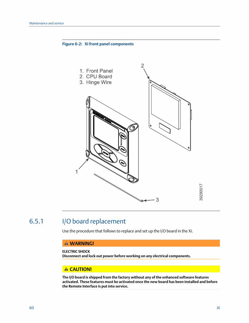
Xi front panel componentsFigure 6-2:
6.5.1 I/O board replacementUse the procedure that follows to replace and set up the I/O board in the Xi.
WARNING!
ELECTRIC SHOCKDisconnect and lock out power before working on any electrical components.
CAUTION!
The I/O board is shipped from the factory without any of the enhanced software featuresactivated. These features must be activated once the new board has been installed and beforethe Remote Interface is put into service.
Maintenance and service
60 Xi

CAUTION!
If the existing I/O board has been operated with the Stoichiometric enhanced software feature,this feature must be activated in the new board before the Xi Electronics is put back intoservice. Failure to do so will cause a false analog output signal to the DCS.
Procedure
1. Loosen the four screws securing the Xi cover.
The screws are captive and do not need to be completely removed.
2. Swing the Xi cover down to expose the inner components.
3. Disconnect the 110-pin ribbon cable from the I/O board.
A new cable is supplied in the replacement kit and should be used if the old one isdamaged.
4. Tag and disconnect wiring for Alarm Outputs, Flame Status Input, and/or SPS/IMPSas applicable.
5. Slide the I/O board part way out of the Xi enclosure.
6. Disconnect the 4-position plug for the transmitter probe and output wiring. Removethe I/O board completely from the Xi enclosure.
7. See Figure 6-3. Set jumpers JP1, JP2, JP5, JP7, and JP8 to their proper positions usingthe old I/O board as a guide.
I/O board jumper and switch settingsFigure 6-3:
8. Set switch SW4 to their proper positions using the old I/O board as a guide.
9. Partially slide the new I/O board into the Xi enclosure. Ensure the board is correctlyaligned within the slots in the enclosure.
10. Connect the 4-position plug for the transmitter probe and output wiring. Slide theI/O board completely into the Xi enclosure.
Maintenance and service
Reference Manual 61

11. Reinstall wiring for Alarm Outputs, Flame Status Input, and/or SPS/IMPS asapplicable.
See Figure 6-4 and Figure 6-5 for wiring diagrams. See Figure 6-6 for I/O boardpositions in the Xi enclosure.
I/O board wiring connectionsFigure 6-4:
I/O board flame safety interlock wiringFigure 6-5:
Maintenance and service
62 Xi

I/O board positions in the enclosureFigure 6-6:
12. Connect the ribbon cable to the I/O board.
A new cable is supplied and should be used if the old one is damaged.
13. Swing the Xi cover up in place and tighten the four screws.
14. Prior to operating the O2 probe and the Xi, all optional software enhancements(previously enabled or not) must be enabled.
Notify Rosemount and reference the following part numbers to enable the softwarerelated options.
Maintenance and service
Reference Manual 63

Part number Software option
6A00269G01 Enhanced software option upgrade, stoichiometric function
6A00269G02 Enhanced software option upgrade, programmable reference function
6A00269G03 Enhanced software option upgrade, 850 °C process function
NOTICEFor enhanced software upgrades or to enable optional software features previouslyused in your Xi configuration, contact Rosemount at 1-800-433-6076.
15. Recalibrate the O2 probe according to the applicable calibration instructions in Chapter 4.
6.5.2 AC relay board replacementUse the procedure that follows to replace and set up the AC relay board in the Xi.
WARNING!
Disconnect and lock out power before working on any electrical components.
Procedure
1. Loosen the four screws securing the Xi cover.
The screws are captive and do not need to be completely removed.
2. Swing the Xi cover down to expose the inner components.
3. Tag and disconnect wiring for the Relay In.
4. Slide the AC relay board part way out of the Xi enclosure.
5. Tag and disconnect the 3-position plugs for the AC input and transmitter probeheater wiring. Remove the AC relay board completely from the enclosure.
6. Partially slide the new AC relay board into the Xi enclosure. Ensure the board iscorrectly aligned within the slots in the enclosure.
7. Connect the two 3-position plugs for the AC input and transmitter probe heaterwiring. Slide the AC relay board fully into the Xi enclosure.
8. Reinstall wiring for Relay In.
See Figure 6-7 for wiring diagram.
Maintenance and service
64 Xi

I/O and AC relay board flame safety interlock wiringFigure 6-7:
9. Swing the cover up in place and tighten the four screws.
CAUTION!Installing and configuring an AC relay board for the flame status interlock function willdedicate alarm output 2 for this function. Once configured for flame status interlock, thesoftware will override any previous alarm assignments for alarm output 2 and not allowit to be used for any other function.
6.5.3 Power supply board replacementUse the procedure that follows to replace the power supply board in the Xi. Use thisprocedure to replace an original linear power supply board or the current configurationswitching power supply board.
WARNING!
ELECTRIC SHOCKDisconnect and lock out power before working on any electrical components.
Procedure
1. Loosen the four screws securing the Xi cover.
The screws are captive and do not need to be completely removed.
2. Swing the Xi cover down to expose the inner components.
Maintenance and service
Reference Manual 65

3. Refer to the wiring diagram in Figure 6-8. Unplug the AC input wiring plug from thepower supply board.
A new plug is supplied in the replacement kit and should be used if the existing plugis damaged.
Power supply board wiringFigure 6-8:
4. Disconnect the 14-pin ribbon cable from the power supply board.
5. Remove the two long screws that secure the bracket (9, Figure 6-1) to the Xienclosure.
6. Hold the AC input wiring to the right and slide the power supply board out of the Xienclosure.
7. Install the new mounting bracket (9, Figure 6-1) on the new power supply board (10, Figure 6-1).
A new bracket and mounting screws are provided in the replacement kit.
8. Slide the power supply board into the mating slots in the Xi enclosure. Make sure theboard is correctly aligned in the slots.
9. Install and tighten the bracket mounting screws.
Two new screws are provided in the replacement kit and should be used if theexisting screws are damaged.
10. Connect the ribbon cable to the power supply board.
A new ribbon cable (7, Figure 6-1) is provided in the replacement kit and should beused if the existing cable is damaged.
Maintenance and service
66 Xi

11. Connect the AC power plug to the power supply board.
12. Swing the Xi cover up and tighten the four mounting screws.
6.5.4 Xi front panel replacementUse the procedure that follows to replace the front panel on the Xi. Replacement kits withand without the CPU board are available. Use the instructions that apply to thereplacement kit you have.
WARNING!
Disconnect and lock out power before working on any electrical components.
Replacing front panel assembly without CPU boardComplete the following steps to replace the front panel assembly without a CPU board.
1. Loosen the four screws securing the Xi cover.
The screws are captive and do not need to be completely removed.
2. Swing the Xi cover down to expose the inner components.
3. Disconnect the 14-pin ribbon cable going to the power supply board.
A new cable is supplied in the replacement kit and should be used if the old one wasdamaged.
4. Disconnect the 10-pin ribbon cable(s) going to the I/O board(s).
One new cable is supplied in the replacement kit and should be used if either of theribbon cables are damaged.
5. Remove the wire hinge from the right side of the Xi cover.
A paper clip or similar device can be inserted into the hole on the left side of thecover to push the hinge out of the cover. A new hinge pin is supplied in thereplacement kit and should be used if the old one is damaged.
6. Position the new front panel assembly in place and reinstall the hinge pin. Ensure thehinge pin is fully seated into the Xi cover.
CAUTION!EQUIPMENT DAMAGE
The new front panel assembly may be supplied with protective clear membranes overthe interior and exterior of the window. Failure to remove the exterior protectivemembrane may cause the display to be distorted. The membrane may be difficult orimpossible to remove after extended use at elevated temperatures.
7. The keypad window on the new front panel may be supplied with interior andexterior protective membranes. Remove the protective membranes prior to finalassembly and use of the Xi enclosure.
8. Reconnect the 10-pin ribbon cable from the I/O board.
Maintenance and service
Reference Manual 67

9. Reconnect the 14-pin ribbon cable from the power supply board.
10. Swing the Xi cover up in place and tighten the four screws.
11. If necessary, configure the appearance of the main display.
Refer to Chapter 3.
Replacing front panel assembly with CPU boardComplete the following steps to replace the front panel assembly with a CPU board.
1. Loosen the four screws securing the Xi cover.
The screws are captive and do not need to be completely removed.
2. Swing the Xi cover down to expose the inner components.
3. Disconnect the 14-pin ribbon cable going to the power supply board.
A new cable is supplied in the replacement kit and should be used if the old one wasdamaged.
4. Disconnect the 10-pin ribbon cable(s) going to the I/O board(s).
One new cable is supplied in the replacement kit and should be used if either of theribbon cables are damaged.
5. Remove the wire hinge from the right side of the Xi cover.
A paper clip or similar device can be inserted into the hole on the left side of thecover to push the hinge out of the cover. A new hinge pin is supplied in thereplacement kit and should be used if the old one is damaged.
6. Place the front panel assembly on the bench. Remove the four screws securing theCPU board to the front cover.
NOTICEPrior to disassembly, observe the position of the plastic bumper with rubber insert as itis installed over the CPU board. The two longer screws are used at the top edge of theCPU board passing through the bumper.
7. Lift the CPU board off of the front cover using care not to damage the board.
8. Disconnect the keypad overlay ribbon from the CPU board. Discard the used frontcover with the keypad overlay attached.
CAUTION!EQUIPMENT DAMAGE
The new front panel assembly may be supplied with protective clear membranes overthe interior and exterior of the window. Failure to remove the exterior protectivemembrane may cause the display to be distorted. The membrane may be difficult orimpossible to remove after extended use at elevated temperatures.
Maintenance and service
68 Xi

9. The keypad window on the new front panel may be supplied with interior andexterior protective membranes. Remove the protective membranes prior to finalassembly and use of the Xi enclosure.
10. Clean the inside of the keypad overlay window and LCD display window to removefingerprints and accumulated dust.
Use only a soft cloth; do not use any detergents or chemicals.
11. Connect the keypad overlay ribbon cable on the new front panel assembly to theCPU board.
Use care not to damage the board.
12. Position the CPU board in place in the front panel assembly.
13. Reinstall the bumper and 4 screws to secure the CPU board in place.
The two longer screws are used with the plastic bumper on the top edge of the CPUboard.
14. Position the front panel assembly and reinstall the hinge pin. Ensure the hinge pin isfully seated into the Xi cover.
15. Reconnect the 10-pin ribbon cable from the I/O board.
16. Reconnect the 14-pin ribbon cable from the power supply board.
17. Swing the Xi cover up in place and tighten the four screws.
18. If necessary, configure the appearance of the main display.
Refer to Chapter 3.
6.5.5 DR board replacementUse the procedure that follows to replace the DR board in the Xi that is connected to adirect replacement probe.
WARNING!
ELECTRIC SHOCKDisconnect and lock out power before working on any electrical components.
Procedure
1. Loosen the four screws securing the Xi cover.
The screws are captive and do not need to be completely removed.
2. Swing the Xi cover down to expose the inner components.
3. Slide the DR board part way out of the Xi enclosure.
4. Unplug the wiring harness plug from the connector J8 located on the bottom, left-hand side of the board.
Refer to Figure 6-9.
Maintenance and service
Reference Manual 69

DR board wiring, right-hand sideFigure 6-9:
Maintenance and service
70 Xi

5. Unplug the wiring harness plugs from the connectors J1, J2, and J3 located on thetop, right-hand side of the board. Refer to Figure 6-10.
DR board wiring, left-hand sideFigure 6-10:
6. Tag and disconnect the wiring to connector J4.
7. Remove the DR board from the Xi enclosure.
8. Partially slide the new DR board into the mating slots in the Xi enclosure. Make surethe board is correctly aligned in the slots.
9. Refer to the wiring diagram in Figure 6-9. Reconnect the wiring to connector J4.
10. Connect the wiring harness plugs to connectors J1, J2, J3, and J8.
Maintenance and service
Reference Manual 71

11. Slide the DR board completely into the Xi enclosure.
12. Swing the Xi cover up and tighten the four mounting screws.
Maintenance and service
72 Xi

7 Replacement parts
7.1 Xi electronics
Replacement parts for XiTable 7-1:
Part number Description
6A00265G01 Kit, power supply board (obsolete - replaced by 6A00329G01)
6A00329G01 Kit, switching power supply board
6A00266G01 Kit, I/O board(1)
6A00267G01 Kit, AC relay board
6A00328G01 Kit, DR board
6A00268G01 Kit, front panel with overlay and CPU board
6A00268G02 Kit, front panel with overlay
6A00269G01 Enhanced software option upgrade, Stoichiometric function
6A00269G02 Enhanced software option upgrade, programmable reference function
6A00269G03 Enhanced software option upgrade, 800 °C process function
6A00237H24 Kit, pipe and wall mount
6A00237H33 Kit, panel mount
6A00243G01 Ribbon cable, 10 pin (CPU board to I/O board)
6A00242G01 Ribbon cable, 14 pin (CPU board to power supply board)
6A00291H01 Insulator
6A00381G01 Kit, hole plug and gland
6A00285H01 Gasket, panel
6A00287H01 Gasket, cover
(1) If the existing I/O board has been operated with the Stoichiometric enhanced software feature, this featuremust be activated in the new board before the Xi is put back into service. Failure to do so will cause a falseanalog output signal to the DCS.
Replacement parts
Reference Manual 73

7.2 Calibration components
Replacement parts for calibration componentsTable 7-2:
Part number Description
1A99119G01 Calibration gas bottles -0.4% and 8% O2, balance nitrogen - 550 liters each(1)
1A99119G02 Two flow regulators (for calibration gas bottles)
1A99119G03 Bottle rack
(1) Calibration gas bottles cannot be shipped via airfreight.
Replacement parts
74 Xi

8 Optional accessories
8.1 HART handheld 375/475 Field Communicator
375/475 Field CommunicatorFigure 8-1:
The 375/475 Field Communicator is an interface device that provides a commoncommunication link to HART-compatible instrument, such as the Xi. HARTcommunications protocol permits all the information available from the Xi-s electronics tobe transmitted over standard 4-20 mA signal wires. By attaching the 375/475 FieldCommunicator at a termination point along the 4-20 mA signal line, you can diagnoseproblems and configure and calibrate the Xi as if you were standing in front of theinstrument.
For more information, call Rosemount at 1-800-433-6076.
Optional accessories
Reference Manual 75

8.2 Asset Management Solutions (AMS)Asset Management Solutions (AMS) software works in conjunction with the HART®
communication protocol and offers the capability to communicate with all HART plantdevices from a single computer terminal.
For more information, call Rosemount at 1-800-433-6076.
8.3 By-Pass PackagesThe specially designed Rosemount By-Pass Package for oxygen analyzers has proven towithstand the high temperatures in process heaters while providing the same advantagesoffered by the in situ sensor. Inconel steel tubes provide effective resistance to corrosion,and the package uses no moving parts, air pumps, or other components common to othersampling systems.
For more information, call Rosemount at 1-800-433-6076.
By-Pass PackagesFigure 8-2:
Optional accessories
76 Xi

8.4 Rosemount SPS 4001B Single ProbeAutocalibration Sequencer
Rosemount SPS 4001BFigure 8-3:
Rosemount specifically designed the SPS 4001B Single Probe Autocalibration Sequencer toprovide the ability to perform automatic or on-demand calculations. The Rosemount SPS4001B is fully enclosed in a NEMA cabinet suitable for wall-mounting. This cabinet providesadded protection against dust and minor impacts.
The Rosemount SPS 4001B works in conjunction with the Rosemount 6888Xi, eliminatingout-of-calibration occurrences and the need to send a technician to the installation site.
For more information, call Rosemount at 1-800-433-6076.
Optional accessories
Reference Manual 77
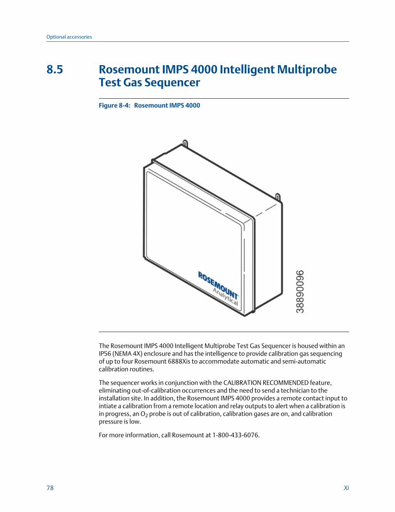
8.5 Rosemount IMPS 4000 Intelligent MultiprobeTest Gas Sequencer
Rosemount IMPS 4000Figure 8-4:
The Rosemount IMPS 4000 Intelligent Multiprobe Test Gas Sequencer is housed within anIP56 (NEMA 4X) enclosure and has the intelligence to provide calibration gas sequencingof up to four Rosemount 6888Xis to accommodate automatic and semi-automaticcalibration routines.
The sequencer works in conjunction with the CALIBRATION RECOMMENDED feature,eliminating out-of-calibration occurrences and the need to send a technician to theinstallation site. In addition, the Rosemount IMPS 4000 provides a remote contact input tointiate a calibration from a remote location and relay outputs to alert when a calibration isin progress, an O2 probe is out of calibration, calibration gases are on, and calibrationpressure is low.
For more information, call Rosemount at 1-800-433-6076.
Optional accessories
78 Xi

8.6 O2 calibration gas
Calibration Gas BottlesFigure 8-5:
Rosemount's O2 calibration gas and service kits have been carefully designed to provide amore convenient and fully portable means of testing, calibrating, and servicingRosemount's oxygen analyzers. These lightweight, disposable gas cylinders eliminate theneed to rent gas bottles.
For more information, call Rosemount at 1-800-433-6076.
Optional accessories
Reference Manual 79

8.7 OxyBalance Display and Averaging System
OxyBalanceFigure 8-6:
The optional OxyBalance Display and Averaging System reviews up to eight 4-20 mAsignals from individual probes. It trends individual outputs and calculates fourprogrammable averages as additional 4-20 mA inputs.
For more information, call Rosemount at 1-800-433-6076.
Optional accessories
80 Xi
Appendix AXPS information
A.1 XPS equipment descriptionThe XPS is primarily an interfacing electronics box installed between an O2 probe and theXi electronics. There are three variants of the XPS electronics box, each with specificfunctions.
1. Remote XPS - 6A00358G01 for 44 V probes
2. Remote XPS - 6A00358G03 for 115 V probes
3. Integral XPS - 6A00365G01 for 44 V probes
A.1.1 Remote XPS for 44 V probes - 6A00358G01This version of the XPS is for use with Westinghouse/Rosemount World Class probes thatuse a 44 volt heater and when the O2 probe uses a 120/240 V, 50/60 Hz power source. The6A00358G01 version contains electronics to recieve and process multiple raw signals fromthe probe.
Signal wires between the O2 probe and the G01 version XPS include the following:
1. Thermocouple - 2 conductors (type K lead wire)
2. Sensing cell - 2 conductors
3. Heater - 3 conductors
4. Shield
This version of the XPS provides for probe heater control and signal conditioning. Thesignal conditioning electronics result in a linear 4-20 mA %O2 signal.
No operator interface is included. Thereby, the 4-20 mA signal typically goes to an Xiadvanced electronics unit. Alternately, a handheld HART 375/475 Field Communicator canbe used as the operator interface. However, the Xi or the field communicator must be thededicated communication device. The Xi and the field communicator cannot be used atthe same time.
For heater control, the G01 version of the XPS includes a transformer. The transformerconverts 120/240 Vac input power to the 44 Vac heater voltage used in the Westinghouse/Rosemount World Class probe.
XPS information
Reference Manual 81
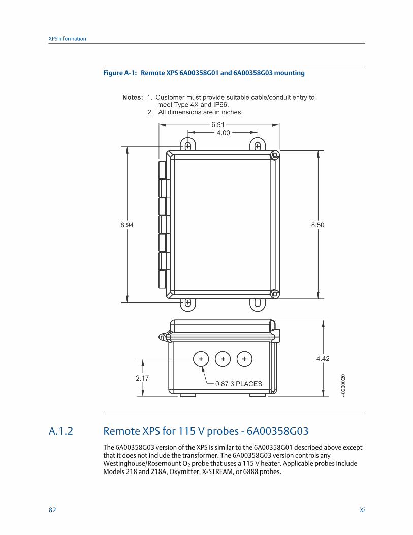
Remote XPS 6A00358G01 and 6A00358G03 mountingFigure A-1:
A.1.2 Remote XPS for 115 V probes - 6A00358G03The 6A00358G03 version of the XPS is similar to the 6A00358G01 described above exceptthat it does not include the transformer. The 6A00358G03 version controls anyWestinghouse/Rosemount O2 probe that uses a 115 V heater. Applicable probes includeModels 218 and 218A, Oxymitter, X-STREAM, or 6888 probes.
XPS information
82 Xi

A.1.3 Integral XPS 6A00365G01 with Xi (for 44 V probes)This XPS equipment configuration includes the XPS and an Xi Advanced Electronics unitinstalled on a mounting plate. This configuration is intended to replace a world classintelligent field transmitter (IFT) where the required input line voltage is 120/240 Vac,particularly for 240 Vac applications.
Integral XPS with Xi and 6A00365G01 mountingFigure A-2:
A.1.4 Other XPS usesThe XPS units can be wired to two O2 probes and back to one dual-channel Xi. This avoidshaving to purchase an Xi for each probe and eliminates one of two signal cables that wouldotherwise be required to communicate between the Xi and XPS units.
XPS information
Reference Manual 83

Remote XPS 6A00358G01 wiring diagramFigure A-3:
XPS information
84 Xi
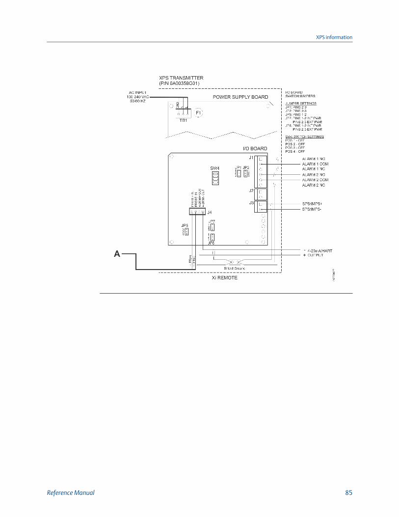
XPS information
Reference Manual 85

Remote XPS 6A00358G03 wiring diagramFigure A-4:
XPS information
86 Xi

XPS information
Reference Manual 87

Integral XPS 6A00365G01 wiring diagramFigure A-5:
XPS information
88 Xi

XPS information
Reference Manual 89
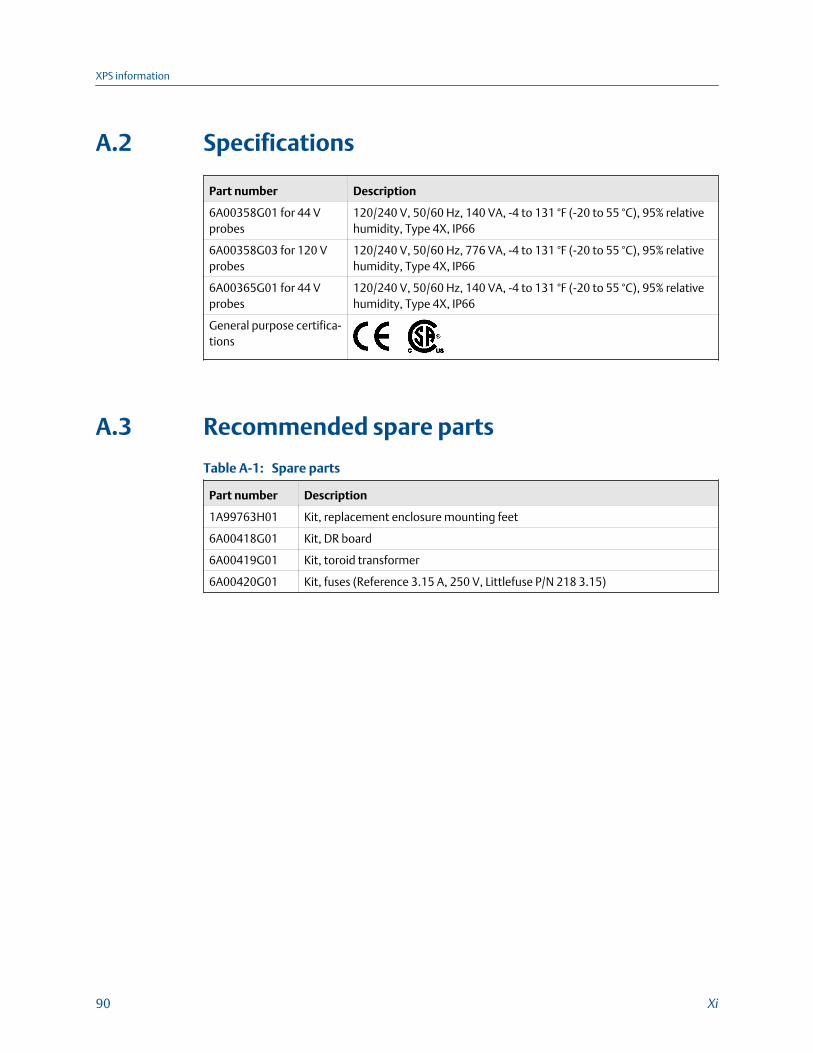
A.2 Specifications
Part number Description
6A00358G01 for 44 Vprobes
120/240 V, 50/60 Hz, 140 VA, -4 to 131 °F (-20 to 55 °C), 95% relativehumidity, Type 4X, IP66
6A00358G03 for 120 Vprobes
120/240 V, 50/60 Hz, 776 VA, -4 to 131 °F (-20 to 55 °C), 95% relativehumidity, Type 4X, IP66
6A00365G01 for 44 Vprobes
120/240 V, 50/60 Hz, 140 VA, -4 to 131 °F (-20 to 55 °C), 95% relativehumidity, Type 4X, IP66
General purpose certifica-tions
A.3 Recommended spare parts
Spare partsTable A-1:
Part number Description
1A99763H01 Kit, replacement enclosure mounting feet
6A00418G01 Kit, DR board
6A00419G01 Kit, toroid transformer
6A00420G01 Kit, fuses (Reference 3.15 A, 250 V, Littlefuse P/N 218 3.15)
XPS information
90 Xi

Appendix BService support
To expedite the return process outside of the United States, contact the nearestRosemount™ representative.
Within the United States, call the Emerson™ Instrument and Valves Response Center usingthe 1-800-654-RSMT (7768) toll-free number. This center, available 24 hours a day, willassist you with any needed information or materials.
The center will ask for product model and serial numbers and will provide a Return ofMaterial Authorization (RMA) number. The center will also ask for the process material towhich the product was last exposed.
Service support
Reference Manual 91

00809-0100-4889
Rev AA
2018
GLOBAL HEADQUARTERSEmerson Automation Solutions6021 Innovation BlvdShakopee, MN 55379, USA
+1 800 999 9307 or +1 952 906 8888
+1 952 949 7001
NORTH AMERICARosemount8200 Market BoulevardChanhassen, MN 55317
+1 800 999 9307
+1 952 949 7001
EUROPEEmerson Automation SolutionsNeuhofstrasse 19a P.O. Box 1046CH-6340 BaarSwitzerland
+ 41 (0) 41 768 6111
+ 41 (0) 41 768 6300
MIDDLE EAST AND AFRICAEmerson Automation SolutionsEmerson FZEJebel Ali Free ZoneDubai, United Arab Emirates, P.O. Box 17033
+971 4 811 8100
+971 4 886 5465
ASIA-PACIFICEmerson Automation Solutions1 Pandan CrescentSingapore 128461Singapore
+65 777 8211
+65 777 0947
Linkedin.com/company/Emerson-Automation-Solutions
twitter.com/rosemount_news
Facebook.com/Rosemount
youtube.com/RosemountMeasurement
google.com/+RosemountMeasurement
AnalyticExpert.com
©2018 Emerson. All rights reserved.
The Emerson logo is a trademark and service mark of Emerson Electric Co. Rosemount is amark of one of the Emerson family of companies. All other marks are the property of theirrespective owners.


