59
V1.00 JUNCTION 5 USER TUTORIALS

V1.00
JUNCTION 5 USER TUTORIALS

Junction 5 User Tutorials
Version: 1.00 Page: 2
Junction 5
3D Object Design Tool
User Tutorials
V1.00
Junction 5 User Tutorials
Version: 1.00 Page: 3
Copyright
This material is copyright © 2011 The Primal Soup Inc.
All Rights Reserved.
Notice: The internal programs that control this product are copyrighted and all rights
are reserved. Reproductions, adaptation, recompiling, or translation of these programs
without prior written permission of NewCo is prohibited. All brand names of products
or software applications used in this manual are copyright and/or trademark protected
by their respective owners.
Junction 5 User Tutorials
Version: 1.00 Page: 4
Disclaimer
This manual and any examples contained herein are provides “as is” and are subject to
change without notice. The producer of this manual accepts no responsibility for
damage or claims, resulting from misuse or misinterpretation. NewCo Capability
Engineering, Inc, its employees, or contractors shall not be liable for any errors, for
incidental, or consequential damages in connection with the furnishing, performance,
use of this manual, or examples herein.

Junction 5 User Tutorials
Version: 1.00 Page: 5
Table of Contents
CONTENTS Welcome ............................................................................................................................. 6
Tutorial Information ........................................................................................................... 7
Tutorial One: Setting up 3 View Build Reference Plane ...................................................... 8
Tutorial Two: Basic Modelling - Extrude ........................................................................... 22
Tutorial Three: Adding Special Effects to an ESP/FSX Model............................................ 27
Tutorial Four: Degrees of Freedom/ Part Articulation ...................................................... 34
Tutorial Five: Build a Wing ................................................................................................ 46

Junction 5 User Tutorials
Version: 1.00 Page: 6
WELCOME
Welcome to the Junction 5 User Tutorials. This document contains information on how
to use the features and capabilities of Junction 5. Additional on-line tutorials are
available from our website as a companion to this manual at the following web site:
http://www.NewCo.com/tutorials/
The Junction 5 application is a powerful integrated 3D modelling tool for real time
graphics. This application has been specifically engineered for the Modelling, Simulation
and Gaming (MS&G) industry with support for standard 3D formats with tools made by
modellers for modellers. Now it is easier than ever to share your models across synthetic
environments. This simple to use tool set enables artists and modellers to quickly
produce stunning quality models and environments in less time.
Junction 5 is the first content development tool to support the new Lockheed Martin
Prepar3D® simulation platform and incorporates many advanced features that allow the
easy reuse of content from legacy systems. Microsoft Flight Simulator X model
development and export is included and our DirectX .x model format support allows
opportunities to develop content for Microsoft® XNA™, Microsoft® Xbox™ and many
other simulation and 3D game development environments.
Now it is easier than ever to share your models across synthetic environments, or create
new models. It’s easy to learn environment enables artists and modellers to quickly
produce stunning quality models and environments in less time.
If you are new to this software, it is suggested that you begin with the Getting Started
Guide in the User Manual. Also visit our on-line support forum
(http://forums.NewCo.com) where you will be able to get additional technical support
and assistance from NewCo and the user community and also get tips and free models.
Junction 5 User Tutorials
Version: 1.00 Page: 7
TUTORIAL INFORMATION
There are five tutorials in this manual.
1. Setting up a 3 View Build Reference Plane
2. Basic Modelling - Extrude
3. Adding Special Effects to an ESP/FSX Model
4. Degrees of Freedom/Part Articulation
5. Build a Wing

Junction 5 User Tutorials
Version: 1.00 Page: 8
TUTORIAL ONE: SETTING UP 3 VIEW BUILD
REFERENCE PLANE
This tutorial will explain how to set up a basic 3 View Build Reference Plane. These assist
the modeller by providing reference images in the background to assist in creating
geometry of correct proportions.
S T E P 1
Start off with a Cube primitive:

Junction 5 User Tutorials
Version: 1.00 Page: 9
S T E P 2
Rename the Object and Group Node from Cube to View and all the sides of the cube as
shown below. This is so that you can keep track of the 3 view reference as you model.
This basic view cube and other models from this tutorial are saved in
NewCo 3D Modeller/Tutorials/Tutorial 1.
S T E P 3
Next, select each mesh and Zeroize these to the Y-axis:
Right click on the mesh labelled “Front”, click Selection then Select

Junction 5 User Tutorials
Version: 1.00 Page: 10
Click on the Zeroize icon , check Y Axis then OK.
You will now notice the mesh is lined up on the Y Axis.
Repeat for the other meshes in the following manner (Deselect meshes with the
button after each operation):
“Right”, zeroize on the X Axis
“Top”, zeroize on the Z Axis
“Left” , zeroize on the X Axis
“Bottom” , zeroize on the Z Axis
“Rear” , zeroize on the Y Axis

Junction 5 User Tutorials
Version: 1.00 Page: 11
At the end of these functions, the cube should look like the following image:
S T E P 4
Scale the new shape up to get ready for the application of textures:

Junction 5 User Tutorials
Version: 1.00 Page: 12
S T E P 4
Scale the new shape up to get ready for the application of textures:
S T E P 5
Load in the Texture/s into the Palettes - Textures Palette (top menu bar) for the 3 view:
Store the full path information and then press OK. (You will delete the 3 View
plane when you export the model so you would keep these textures separate
from the model textures - which are normally in the same directory as the
model geometry.)
Junction 5 User Tutorials
Version: 1.00 Page: 13
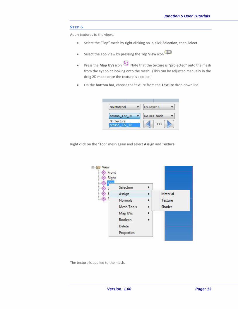
S T E P 6
Apply textures to the views.
Select the “Top” mesh by right clicking on it, click Selection, then Select
Select the Top View by pressing the Top View icon
Press the Map UVs icon Note that the texture is “projected” onto the mesh
from the eyepoint looking onto the mesh. (This can be adjusted manually in the
drag 2D mode once the texture is applied.)
On the bottom bar, choose the texture from the Texture drop-down list
Right click on the “Top” mesh again and select Assign and Texture.
The texture is applied to the mesh.

Junction 5 User Tutorials
Version: 1.00 Page: 14
Because it is a projection onto the mesh from the viewport, we will adjust the placement
of the texture on the mesh by using the UV Drag 2D mode from the side toolbar.
Select the UV Drag 2D mode from the right hand tool bar. (This may not be visible
in the toolbar, but nested within the UV mode tools under the Edit Vertex UV Mode
icon:
The 2D UV mapping window will appear. The red box indicates the current projection of
the UVs. The green dots indicate nodes that can be left clicked and dragged.

Junction 5 User Tutorials
Version: 1.00 Page: 15
Click and drag the green dots on the red box to fill it with the Top drawing of the Cessna.
Use the magnifying glass icon in the top tool bar to zoom the texture to a larger
size.
Tip

Junction 5 User Tutorials
Version: 1.00 Page: 16
Click on the Camera icon to see the newly textured mesh. Don’t worry about the scale
yet, that will be addressed in a subsequent step.
Repeat the step for all other meshes.
Use the middle mouse scroll button to twist the texture left or right for better alignment.
See the User Manual for more details.
Tip

Junction 5 User Tutorials
Version: 1.00 Page: 17
Tip
You will have noticed that the “Right” and “Top” textures need to be flipped so that
they can face the right way. Actually, the easiest way to get around this for this
particular 3 View (because we don’t have a separate rear, top or bottom view in the
texture) is to make the “Left”, “Front” and “Bottom” meshes double sided and delete
the “Right” and “Top” and “Rear” meshes.
Use the Mesh Node Properties window (right click in the mesh and select
Properties) and select the Two Sided Draw Type. This will now show the texture on
both sides of the mesh.

Junction 5 User Tutorials
Version: 1.00 Page: 18
The viewport should now look like this:
S T E P 7
We now Scale the mesh so that the reference 3-View will be the correct size. We
determine that the wingspan for a Cessna 172 is 11 meters.

Junction 5 User Tutorials
Version: 1.00 Page: 19
Select one vertex (as shown by the arrows on the image below) on each edge of the
reference plane using the Select Vertex tool :
Select the Scale tool and rescale the reference plane X-axis to 11 meters:
Junction 5 User Tutorials
Version: 1.00 Page: 20
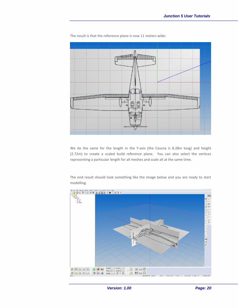
The result is that the reference plane is now 11 meters wide:
We do the same for the length in the Y-axis (the Cessna is 8.28m long) and height
(2.72m) to create a scaled build reference plane. You can also select the vertices
representing a particular length for all meshes and scale all at the same time.
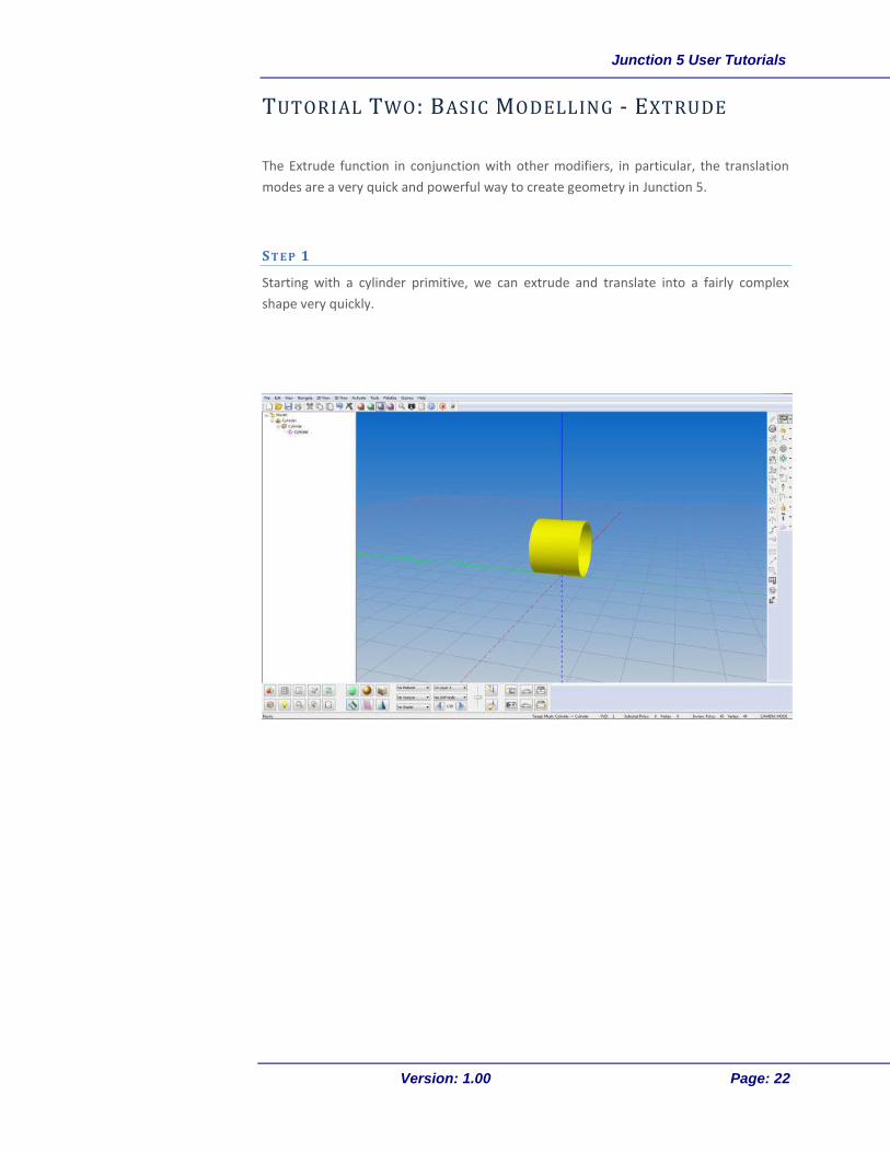
The end result should look something like the image below and you are ready to start
modelling.

Junction 5 User Tutorials
Version: 1.00 Page: 21
Tip
This is just one method of setting up a 3-View Reference Plane, others prefer to use a
box method, we leave it up to your individual style. We prefer using the method
described because it puts the reference planes right on the axis, which makes
mirroring and translation easier. If you prefer the box method, just shift the
reference planes out to where you need them.
Junction 5 User Tutorials
Version: 1.00 Page: 22
TUTORIAL TWO: BASIC MODELLING - EXTRUDE
The Extrude function in conjunction with other modifiers, in particular, the translation
modes are a very quick and powerful way to create geometry in Junction 5.
S T E P 1
Starting with a cylinder primitive, we can extrude and translate into a fairly complex
shape very quickly.
Junction 5 User Tutorials
Version: 1.00 Page: 23
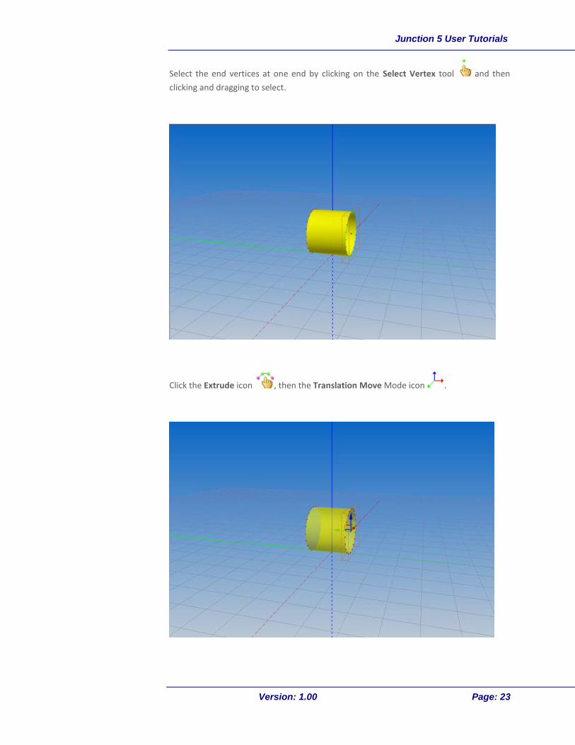
Select the end vertices at one end by clicking on the Select Vertex tool and then
clicking and dragging to select.
Click the Extrude icon , then the Translation Move Mode icon .
Junction 5 User Tutorials
Version: 1.00 Page: 24
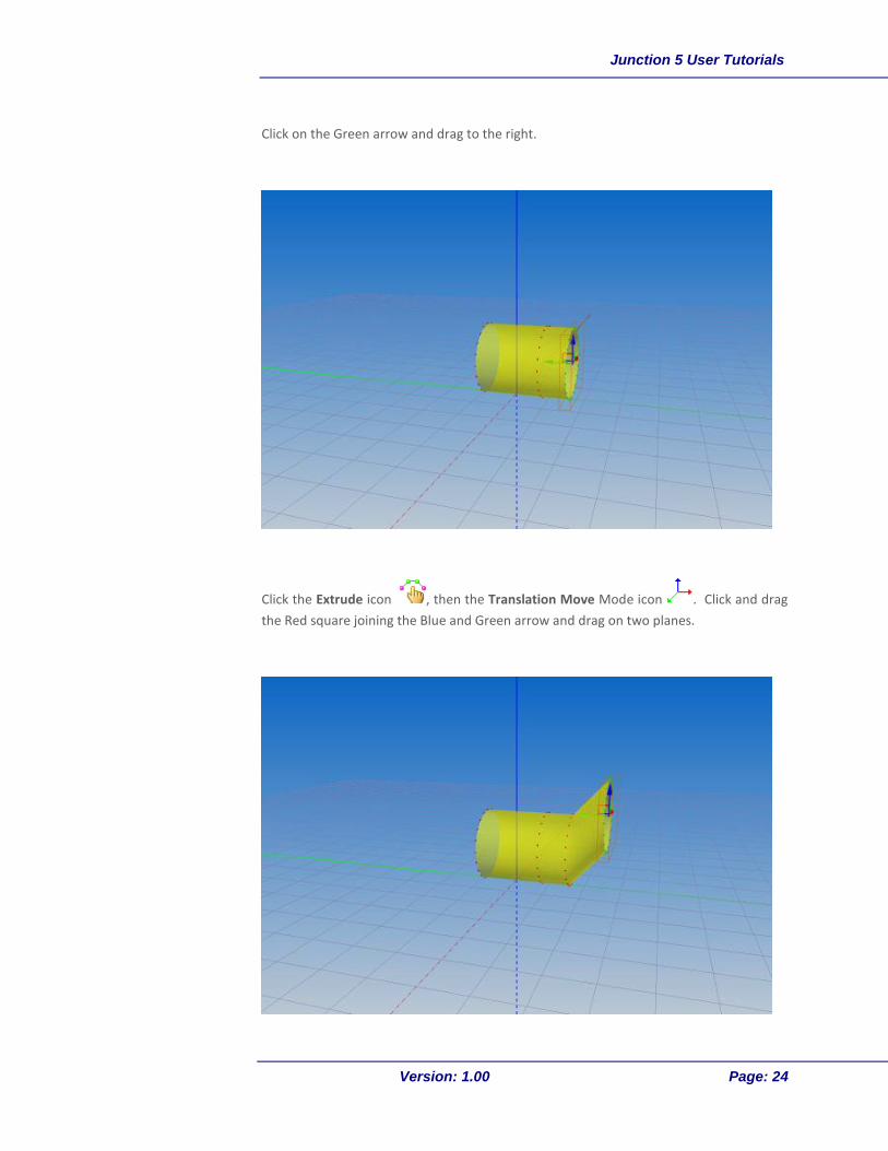
Click on the Green arrow and drag to the right.
Click the Extrude icon , then the Translation Move Mode icon . Click and drag
the Red square joining the Blue and Green arrow and drag on two planes.
Junction 5 User Tutorials
Version: 1.00 Page: 25
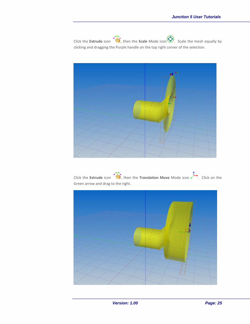
Click the Extrude icon , then the Scale Mode icon . Scale the mesh equally by
clicking and dragging the Purple handle on the top right corner of the selection.
Click the Extrude icon , then the Translation Move Mode icon . Click on the
Green arrow and drag to the right.

Junction 5 User Tutorials
Version: 1.00 Page: 26
Now lets close off the end and create a smaller opening.
Click the Extrude icon , then the Scale Mode icon and click and drag the purple
handle down.
Most kinds of modifiers can be used in conjunction with the Extrude tool to create some
interesting effects.
Junction 5 User Tutorials
Version: 1.00 Page: 27
TUTORIAL THREE: ADDING SPECIAL EFFECTS TO AN
ESP/FSX/PREPAR3D MODEL
This tutorial will show how to add special effects to a model for use within Microsoft®
ESP™, Microsoft® Flight Simulator X™ or Lockheed Martin Prepar3D®. Effects such as
smoke, fire, explosions, exhaust, steam and others are available already in ESP, FSX and
P3D. You can also create effects using the Special Effects SDK and Special Effects Tool
(FXTool) contained in the ESP, FSX or P3D SDK.
S T E P 1
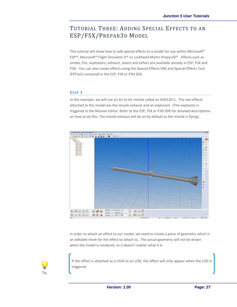
In this example, we will use an Air to Air missile called an AIM120-C. The two effects
attached to this model are the missile exhaust and an explosion. (The explosion is
triggered in the Mission Editor. Refer to the ESP, FSX or P3D SDK for detailed descriptions
on how to do this. The missile exhaust will be on by default as the missile is flying).
In order to attach an effect to our model, we need to create a piece of geometry which is
an editable mesh for the effect to attach to. The actual geometry will not be drawn
when the model is rendered, so it doesn’t matter what it is.
If the effect is attached as a child to an LOD, the effect will only appear when the LOD is
triggered.
Tip
Junction 5 User Tutorials
Version: 1.00 Page: 28
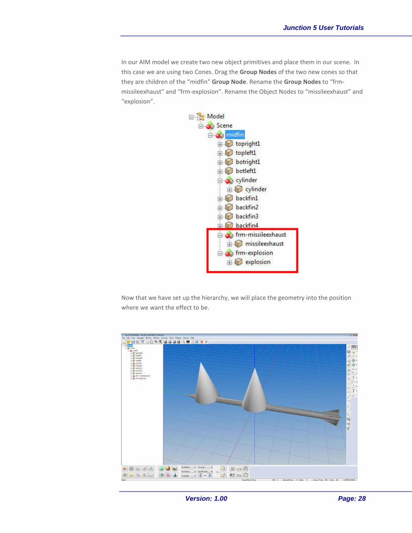
In our AIM model we create two new object primitives and place them in our scene. In
this case we are using two Cones. Drag the Group Nodes of the two new cones so that
they are children of the “midfin” Group Node. Rename the Group Nodes to “frm-
missileexhaust” and “frm-explosion”. Rename the Object Nodes to “missileexhaust” and
“explosion”.
Now that we have set up the hierarchy, we will place the geometry into the position
where we want the effect to be.
Junction 5 User Tutorials
Version: 1.00 Page: 29
S T E P 2
In this step we will resize and place the geometry into position.
As mentioned previously, the geometry that the effect is attached to, disappears once it
is rendered in ESP/FSX, so scale isn’t really an issue, but it would be good to get the
geometry out of the way so that we can still see the rest of the model while we are
working.
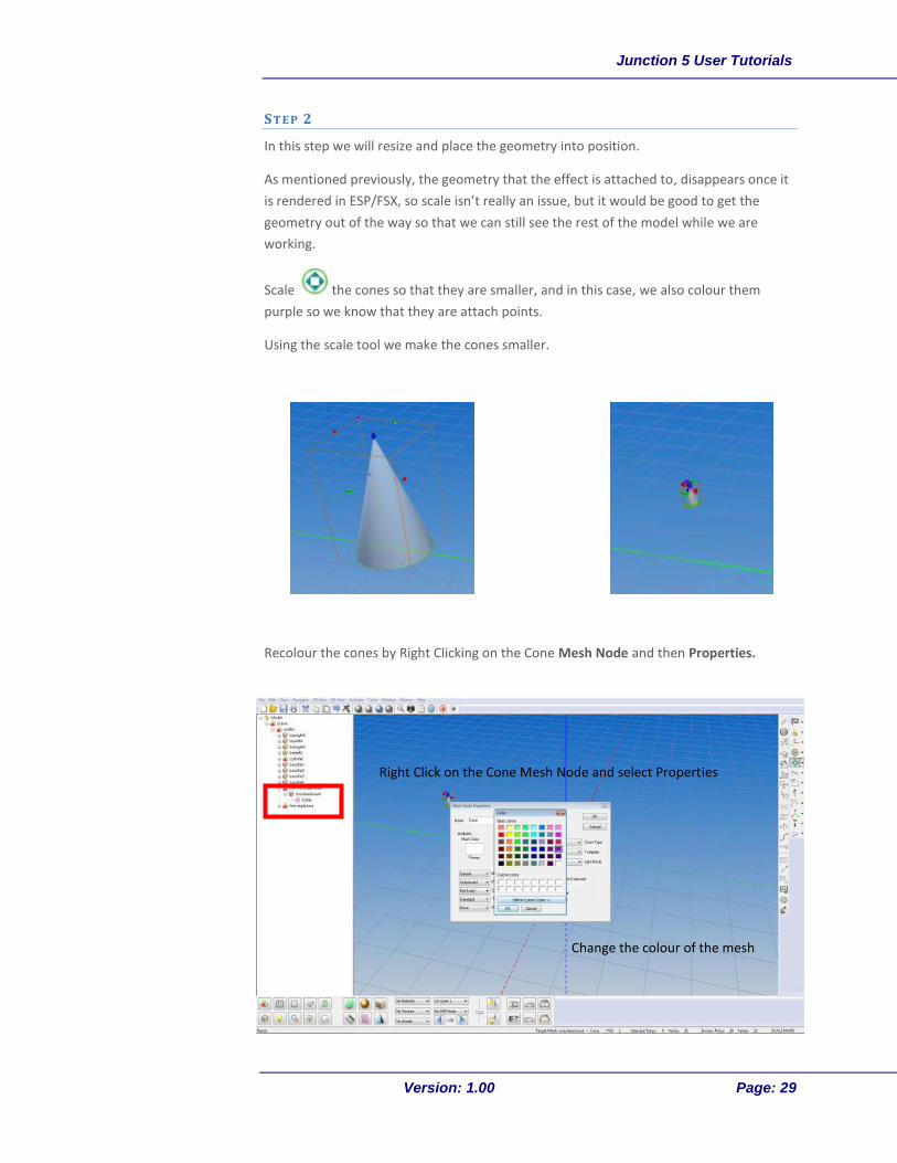
Scale the cones so that they are smaller, and in this case, we also colour them
purple so we know that they are attach points.
Using the scale tool we make the cones smaller.
Recolour the cones by Right Clicking on the Cone Mesh Node and then Properties.
Right Click on the Cone Mesh Node and select Properties
Change the colour of the mesh
Junction 5 User Tutorials
Version: 1.00 Page: 30
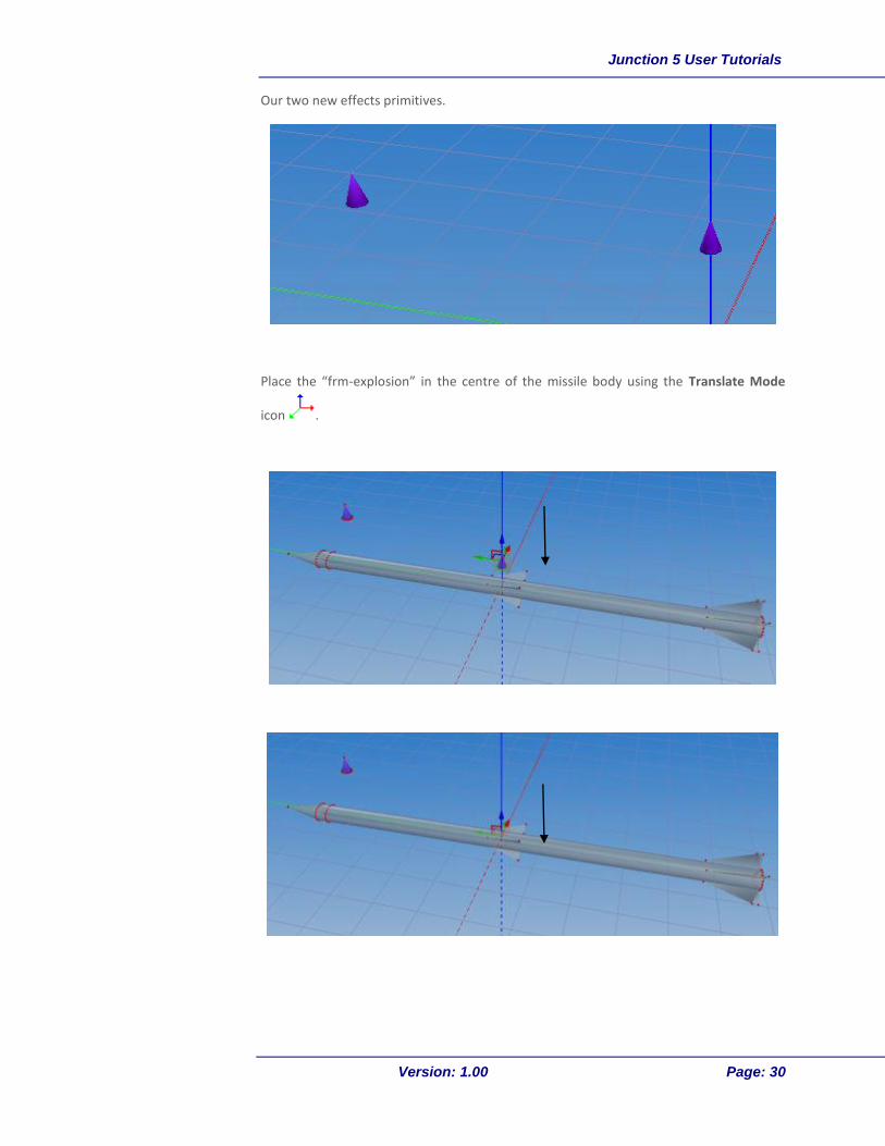
Our two new effects primitives.
Place the “frm-explosion” in the centre of the missile body using the Translate Mode
icon .
Junction 5 User Tutorials
Version: 1.00 Page: 31
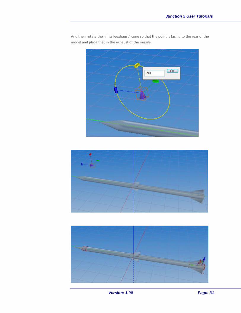
And then rotate the “missileexhaust” cone so that the point is facing to the rear of the
model and place that in the exhaust of the missile.

Junction 5 User Tutorials
Version: 1.00 Page: 32
S T E P 3
Now we will assign an effect to our two special effect attach points. (This step could be
done anytime after creating the attach point geometry, so the order here isn’t
important.)
Right Click on the “missileexhaust” Object Node - Properties
Select Effect and then choose the appropriate effect from the drop-down list. Click OK.
It is useful to come up with a standard schema for your attach points so that you know
when you see it, that it is an attach point. In this example we use purple cones.
Tip
Junction 5 User Tutorials
Version: 1.00 Page: 33
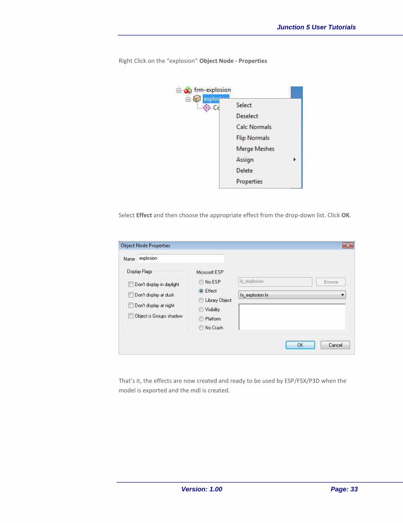
Right Click on the “explosion” Object Node - Properties
Select Effect and then choose the appropriate effect from the drop-down list. Click OK.
That’s it, the effects are now created and ready to be used by ESP/FSX/P3D when the
model is exported and the mdl is created.
Junction 5 User Tutorials
Version: 1.00 Page: 34
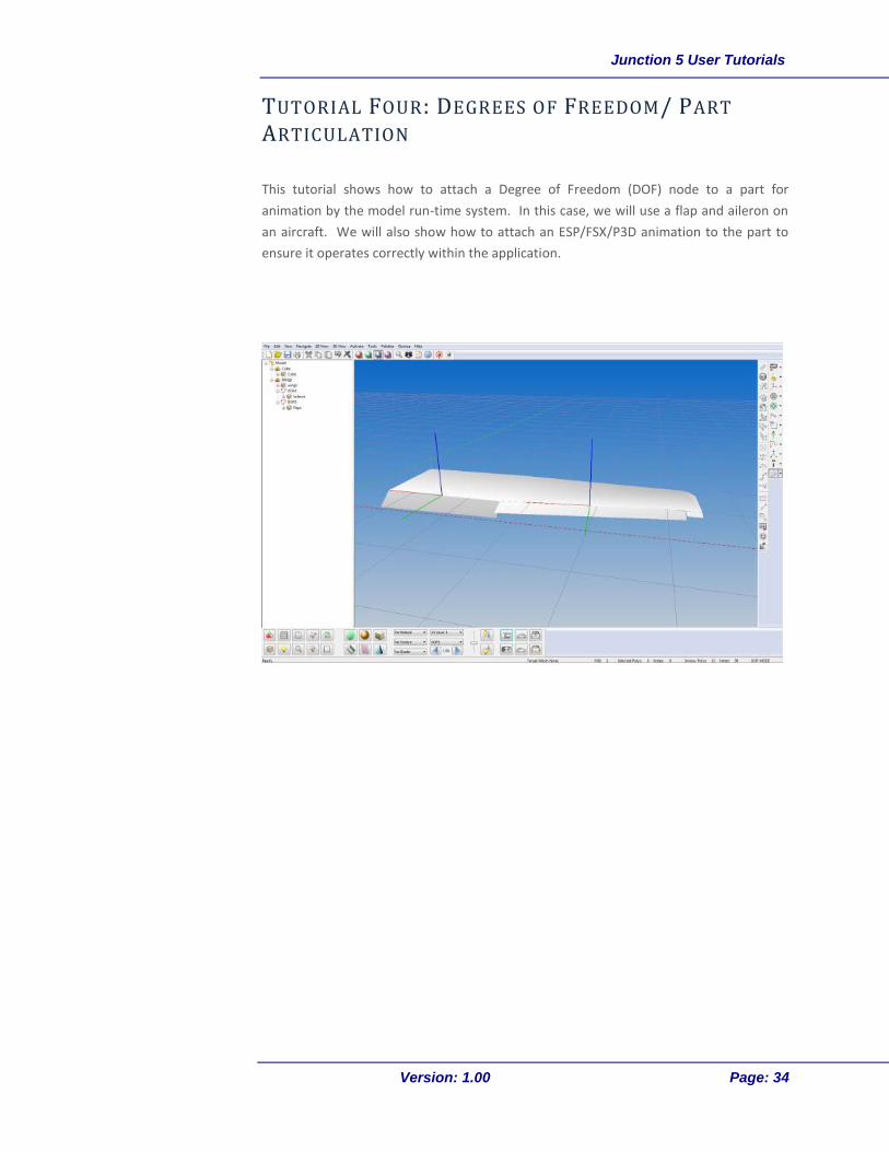
TUTORIAL FOUR: DEGREES OF FREEDOM/ PART
ARTICULATION
This tutorial shows how to attach a Degree of Freedom (DOF) node to a part for
animation by the model run-time system. In this case, we will use a flap and aileron on
an aircraft. We will also show how to attach an ESP/FSX/P3D animation to the part to
ensure it operates correctly within the application.
Junction 5 User Tutorials
Version: 1.00 Page: 35
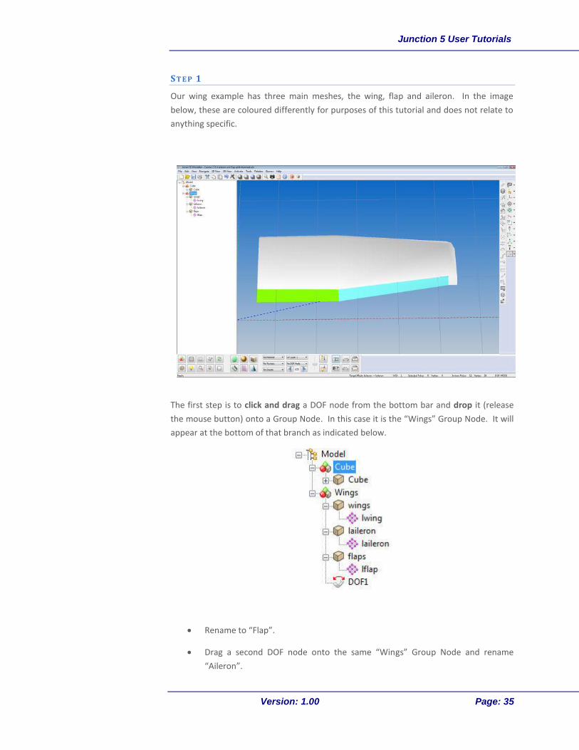
S T E P 1
Our wing example has three main meshes, the wing, flap and aileron. In the image
below, these are coloured differently for purposes of this tutorial and does not relate to
anything specific.
The first step is to click and drag a DOF node from the bottom bar and drop it (release
the mouse button) onto a Group Node. In this case it is the “Wings” Group Node. It will
appear at the bottom of that branch as indicated below.
Rename to “Flap”.
Drag a second DOF node onto the same “Wings” Group Node and rename
“Aileron”.
Junction 5 User Tutorials
Version: 1.00 Page: 36
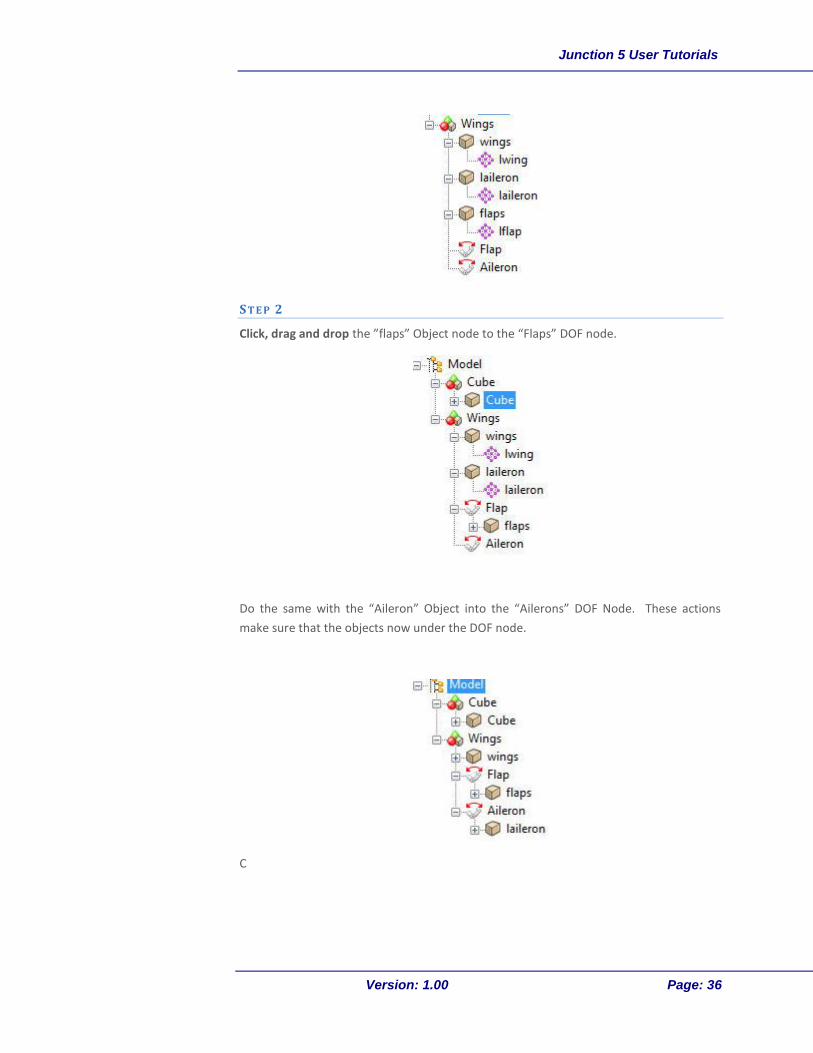
S T E P 2
Click, drag and drop the ”flaps” Object node to the “Flaps” DOF node.
Do the same with the “Aileron” Object into the “Ailerons” DOF Node. These actions
make sure that the objects now under the DOF node.
C

Junction 5 User Tutorials
Version: 1.00 Page: 37
S T E P 3
The next step is to select the two vertices of the part that is to be animated/articulated.
These two vertices are normally on the edge that the part is hinged on.
There are two ways to do this for this particular part. There are only four vertices, so
you can select the whole part (right click on the Object Node press Selection – Select)
and then deselect the two vertices not required using the Select Vertex Tool (right
click and drag across the vertex to deselect), or you can use the Select Vertex Tool
and left click on the two vertices. The first option may seem to be a little bit more
complicated, but it is useful when you have more objects on screen as in the image
above and you want to see the context of the object that you are working on. (So that
we know which side to put the hinge on in this case).

Junction 5 User Tutorials
Version: 1.00 Page: 38
S T E P 4
We now set the DOF to the centre of our object:
Right Click on the Aileron DOF Node icon in the model tree view and select Set to
Centre.
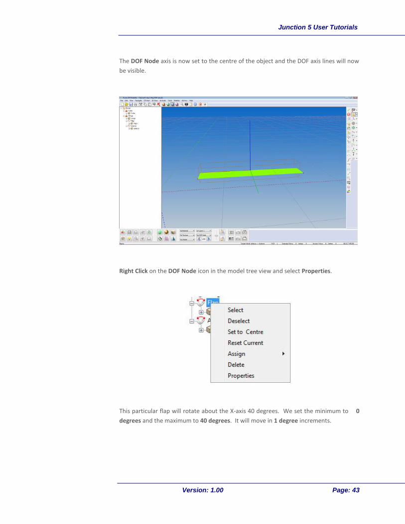
The DOF Node axis is now set to the centre of the object and the DOF axis lines will now
be visible.
Junction 5 User Tutorials
Version: 1.00 Page: 39
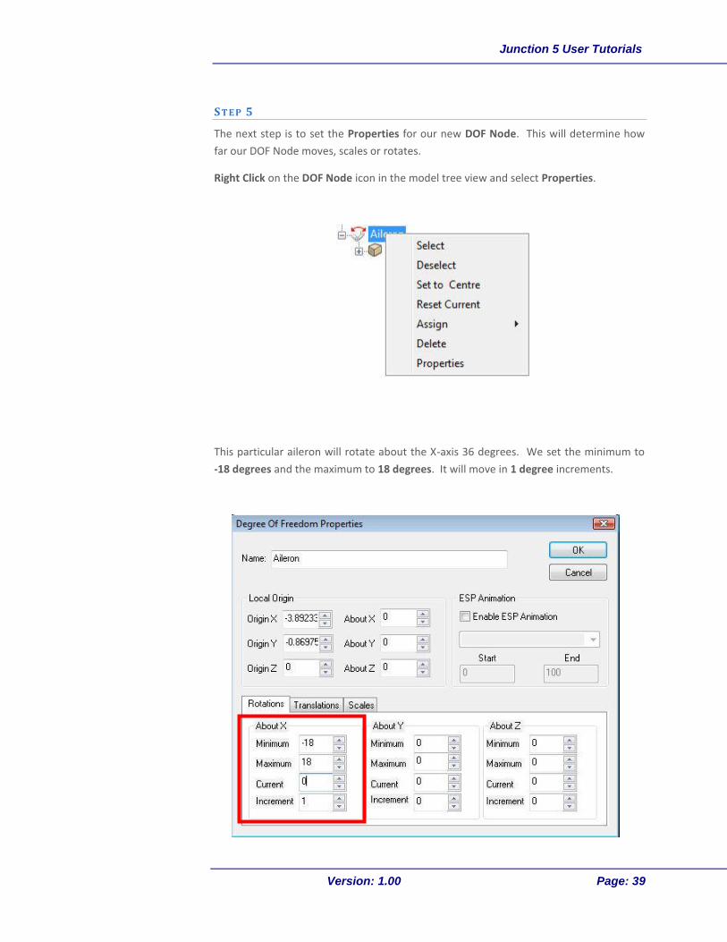
S T E P 5
The next step is to set the Properties for our new DOF Node. This will determine how
far our DOF Node moves, scales or rotates.
Right Click on the DOF Node icon in the model tree view and select Properties.
This particular aileron will rotate about the X-axis 36 degrees. We set the minimum to
-18 degrees and the maximum to 18 degrees. It will move in 1 degree increments.

Junction 5 User Tutorials
Version: 1.00 Page: 40
To see the new articulation on our aileron, select the Exercise DOF Rotations button
on the toolbar and select the Aileron DOF Node from the drop down list on the
Bottom Toolbar.
You will notice that when we exercise the DOF Node that it is rotating about the X-Axis,
but our aileron is actually at an angle to the X-Axis.
To set the correct angle for the offset to the axis, we manually set the angle in the DOF
Properties window. In this case, we set the About Z to match the angle of the part
(which is -6 degrees).

Junction 5 User Tutorials
Version: 1.00 Page: 41
When we exercise the DOF, we now see the part rotating at the correct angle.
ESP/F SX A R T I C U L A T I O N
To make the aileron work in ESP/FSX/P3D, from the DOF Properties screen, enable the
ESP animation by checking the box, select the appropriate animation from the drop-
down list and select OK.
For default animation types, the range of movement is already contained in the
animation file, so rotation angles and motion values do not have to be included.
Start and End figures do not need to be populated unless it is a custom user-created
animation. These numbers represent increments of movement i.e is Start is 0 and End is
100, it breaks down a range of movement into 100 steps.
For our aileron example we use the r_aileron_percent_key as shown in the image
below.
Junction 5 User Tutorials
Version: 1.00 Page: 42
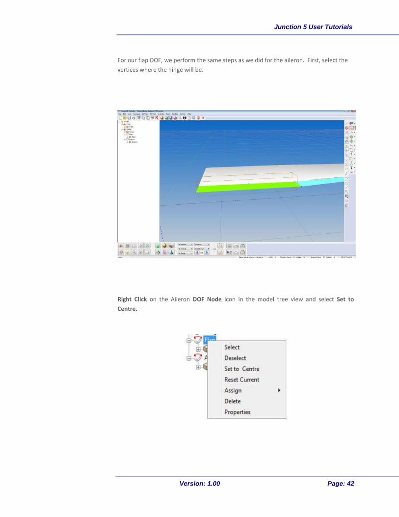
For our flap DOF, we perform the same steps as we did for the aileron. First, select the
vertices where the hinge will be.
Right Click on the Aileron DOF Node icon in the model tree view and select Set to
Centre.
Junction 5 User Tutorials
Version: 1.00 Page: 43
The DOF Node axis is now set to the centre of the object and the DOF axis lines will now
be visible.
Right Click on the DOF Node icon in the model tree view and select Properties.
This particular flap will rotate about the X-axis 40 degrees. We set the minimum to 0
degrees and the maximum to 40 degrees. It will move in 1 degree increments.

Junction 5 User Tutorials
Version: 1.00 Page: 44
The angle needs slight adjustment for the flap, so we change it by 1 degree About Z.
ESP/F SX/P3D A R T I C U L A T I O N
To make the aileron work in ESP/FSX/P3D, from the DOF Properties screen, enable the
ESP animation by checking the box, select the appropriate animation from the drop-
down list and select OK.
For default animation types, the range of movement is already contained in the
animation file, so rotation angles and motion values do not have to be included.

Junction 5 User Tutorials
Version: 1.00 Page: 45
Start and End figures do not need to be populated unless it is a custom user-created
animation. These numbers represent increments of movement i.e is Start is 0 and End is
100, it breaks down a range of movement into 100 steps.
For our flap example we use the r_flap_percent_key as shown in the image below.
Our wing now has working flap and aileron articulations and ESP/FSX/P3D animations.

Junction 5 User Tutorials
Version: 1.00 Page: 46
TUTORIAL FIVE: BUILD A WING
This tutorial combines a number of different functions that will be useful in most
modelling activities. We will build a basic wing structure using various functions to
create the geometry, then use the mesh mirror tool to duplicate the object.
We will use the Cessna template that we generated in a previous tutorial to build the
wing. Start off in the top view.
S T E P 1
In order for us to start drawing polygons to build the wing, we will need to create an
empty mesh that will be used house the polygons as they are drawn. Click and drag a
new Group Node, then Object Node as a child and a Mesh Node as a child of the Object.
Name the new Group Node “Aircraft” and the Object Node “LeftWing” for now.
Select the mesh by right clicking on the mesh icon and clicking on Selection – Select.

Junction 5 User Tutorials
Version: 1.00 Page: 47
S T E P 2
Select the Create Points icon and place helper points around the outline of the wing
as shown. It is good practice to put three helper points on the chord of the wing at each
end and in the middle so that an airfoil shape can be extruded. Also place helper points
at each break for control surfaces to be added.
Helper points are highlighted below to see them easier:

Junction 5 User Tutorials
Version: 1.00 Page: 48
S T E P 3
Use the Create Index Polygon mode tool to connect the helper points together.
Click on the first helper point going from left to right to connect the dots with polygons.
Completed geometry for wing.
S T E P 4
Move from left to right when creating the
polygon. Moving from right to left will
cause the polygon to be flipped.
1 2
3

Junction 5 User Tutorials
Version: 1.00 Page: 49
To create the chord of the wing, we will Select the leading edge vertices and then
Translate them. (Do not select the vertices on the very edge, select the next two up
from the edge.)
Translate the vertices up and out until you are happy with the shape. The vertices can
be individually translated if required.
Junction 5 User Tutorials
Version: 1.00 Page: 50
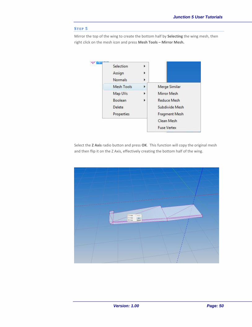
S T E P 5
Mirror the top of the wing to create the bottom half by Selecting the wing mesh, then
right click on the mesh icon and press Mesh Tools – Mirror Mesh.
Select the Z Axis radio button and press OK. This function will copy the original mesh
and then flip it on the Z Axis, effectively creating the bottom half of the wing.
Junction 5 User Tutorials
Version: 1.00 Page: 51
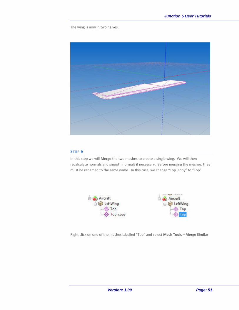
The wing is now in two halves.
S T E P 6
In this step we will Merge the two meshes to create a single wing. We will then
recalculate normals and smooth normals if necessary. Before merging the meshes, they
must be renamed to the same name. In this case, we change “Top_copy” to “Top”.
Right click on one of the meshes labelled “Top” and select Mesh Tools – Merge Similar

Junction 5 User Tutorials
Version: 1.00 Page: 52
Recalculate normals by right clicking on the mesh and selecting Normals – Calc Normals
As can be seen by the above image, the normals will need manual smoothing using the
Smooth Normals tool to eliminate the sharp edge between the newly merged mesh.
Junction 5 User Tutorials
Version: 1.00 Page: 53
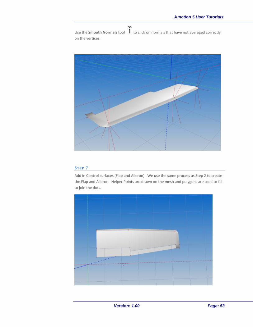
Use the Smooth Normals tool to click on normals that have not averaged correctly
on the vertices.
S T E P 7
Add in Control surfaces (Flap and Aileron). We use the same process as Step 2 to create
the Flap and Aileron. Helper Points are drawn on the mesh and polygons are used to fill
to join the dots.

Junction 5 User Tutorials
Version: 1.00 Page: 54
Using the “Top” 3- View, draw helper points at the corners of the aileron and flap.
Use the Create Polygons mode to draw polygons between the helper points.

Junction 5 User Tutorials
Version: 1.00 Page: 55
I am going to completely cheat at this point for expediency in this tutorial. For the flaps
and ailerons, I will simply create a two sided polygon, rather than a volumetric mesh.
(Normally these would have sides and other mechanical parts attached.)
First we need to split the newly created polygons out of the merged wing. This is done
by Selecting the polygons that make up the Flap and Aileron using the Select by
Polygons Mode .
Use the Translate Drag in Plane mode to drag a vertex/ helper point for fine
placement.
Tip
Junction 5 User Tutorials
Version: 1.00 Page: 56
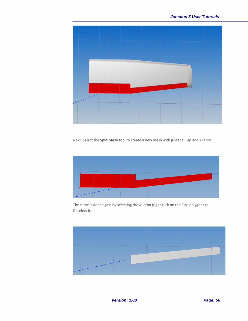
Next, Select the Split Mesh tool to create a new mesh with just the Flap and Aileron.
The same is done again by selecting the Aileron (right click on the Flap polygons to
Deselect it).

Junction 5 User Tutorials
Version: 1.00 Page: 57
There are now three meshes in the LeftWing Object Node. These can be renamed
appropriately.
S T E P 8
Mirror and Flip to create second wing. We repeat Step 5 to create a new left wing and
control surfaces. Select the Wing mesh, then right click on the mesh icon and press
Mesh Tools – Mirror Mesh.
Select the X Axis radio button and press OK. This function will copy the original mesh
and then flip it on the X Axis, effectively creating the left wing.

Junction 5 User Tutorials
Version: 1.00 Page: 58
Repeat for the Flap and Aileron (make sure that if you are using a flat polygon that it is
two sided).
Calculate Normals on the “LeftWing” Object Node.

Junction 5 User Tutorials
Version: 1.00 Page: 59
For more, including animated tutorials, be sure to visit our tutorial website at:
http://www.NewCo.com/tutorials/
and our online support forums at:
http://forums.NewCo.com


