48
June 2008 WEI - L05 sense 1 Wireless Embedded InterNetworking Foundations of Ubiquitous Sensor Networks Triggers and Sensing David E. Culler University of California, Berkeley
| Date post: | 21-Dec-2015 |
| Category: |
Documents |
| View: | 213 times |
| Download: | 0 times |

June 2008 WEI - L05 sense 1
Wireless Embedded InterNetworking
Foundations of Ubiquitous Sensor Networks
Triggers and Sensing
David E. CullerUniversity of California, Berkeley

June 2008WEI - L05 sense 2
An Analog World
• Everything in the physical world is an analog signal– Sound, light, temperature, gravitational force
• Need to convert into electrical signals– Transducers: converts one type of energy to another
» Electro-mechanical, Photonic, Electrical, …
– Examples
» Microphone/speaker
» Thermocouples
» Accelerometers
• And digitize
• Then manipulate

June 2008WEI - L05 sense 3
An Analog World
• Transducers– Allow us to convert physical phenomena to a voltage
potential in a well-defined way.
R ohm ?
V

June 2008WEI - L05 sense 4
Simplest Analog Device
• Often think of it as an actuator, rather than a sensor– But that’s because of the circuit we put it in
• It is binary (two states) but why is it not digital?
switch
Rain Sensor
Magnetic Reed Contact Switch
Tilt Sensor
Water Level Float Sensor
PhotoInterrupter
Flow Sensor
TemperatureSwitch
Pressure Switch

June 2008WEI - L05 sense 5
To Sample a switch, make it digital
• Many sensor are switches
• Two “states” but not digital– Open => no current
– Closed => no voltage drop
• Cap charges to Vacc when open
• Cap discharges to GND when closed
VD
VtL
VtH
Vacc
GND
switch
D

June 2008WEI - L05 sense 6
EPIC I/F Board - Digital Inputs

June 2008WEI - L05 sense 7
Getting Input into the MCU

June 2008WEI - L05 sense 8
MCU – a system on a chip

June 2008WEI - L05 sense 9
Programmed IO

June 2008WEI - L05 sense 10
Interrupts
MCU Hardware
June 2008WEI - L05 sense 11
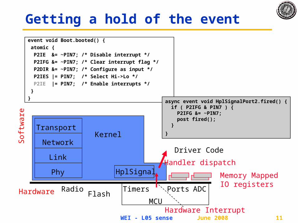
Getting a hold of the event
Hardware
Phy
Link
Network
Transport
HplSignal
RadioFlash
MCU
Ports ADCTimers
Sof
twar
e
Kernel
Driver Code
Memory MappedIO registers
Hardware Interrupt
Handler dispatch
event void Boot.booted() {
atomic {
P2IE &= ~PIN7; /* Disable interrupt */
P2IFG &= ~PIN7; /* Clear interrupt flag */
P2DIR &= ~PIN7; /* Configure as input */
P2IES |= PIN7; /* Select Hi->Lo */
P2IE |= PIN7; /* Enable interrupts */
}
}async event void HplSignalPort2.fired() { if ( P2IFG & PIN7 ) { P2IFG &= ~PIN7; post fired(); }
}

June 2008WEI - L05 sense 12
Making Sense of Physical Information
• Digital representation of physical phenomenon – Transducer => Signal Conditioning => ADC =>
– Conversion to physical units
– Calibration and correction
– Here: 0 / 1, True / False
• Associating meaning to the reading– Open / Closed
– Empty / Full
– In Position / Not
• Depends on the specific device taking the reading
• The Context of the device

June 2008WEI - L05 sense 13
Analog to Digital
• What we want
• How we have to get there
SoftwareSensor ADC
PhysicalPhenomena
Voltage ADC Counts Engineering Units
PhysicalPhenomena
Engineering Units

June 2008WEI - L05 sense 14
Ratiometric sensor
• Va = Vacc* Rsens / (Rcomp+ Rsens)
• use Vref = Vacc
• D = M * Rsens / (Rcomp+ Rsens)
Vacc
GND
Resistive Sensor
VA
Rcomp
Rsensor

June 2008WEI - L05 sense 15
Sampling Basics
• How do we represent an analog signal?– As a time series of discrete values
On the MCU: read the ADC data register periodically
)(xf sampled
)(xf
t
ST
V Counts

June 2008WEI - L05 sense 16
Sampling Basics
• What do the sample values represent?– Some fraction within the range of values
What range to use?
rV
tRange Too Small
rV
tRange Too Big
rV
rV
tIdeal Range
rV
rV

June 2008WEI - L05 sense 17
Sampling Basics
• Resolution– Number of discrete values that
represent a range of analog values
– MSP430: 12-bit ADC
» 4096 values
» Range / 4096 = Step
Larger range less information
• Quantization Error– How far off discrete value is from actual
– ½ LSB Range / 8192
Larger range larger error

June 2008WEI - L05 sense 18
Sampling Basics
• Converting: ADC counts Voltage
• Converting: Voltage Engineering Units
ADCN
4095
4095
RRADCin
RR
RinADC
VVNV
VV
VVN
t
rV
rV
inV
00355.0
986.0TEMP
986.0)TEMP(00355.0
TEMPC
CTEMP
V
V

June 2008WEI - L05 sense 19
Sampling Basics
• Converting values in 16-bit MCUs
vtemp = adccount/4095 * 1.5;
tempc = (vtemp-0.986)/0.00355;
tempc = 0
• Fixed point operations– Need to worry about underflow and overflow
– Avoid divide and (to a lesser degree) multiply
• Floating point operations– They can be costly on the node, but not ridiculous
• Pay attention to overall all contribution to error
00355.0
986.0TEMP TEMP
C
V
4095TEMP
RRADC
VVNV
command uint16_t TempInt.get() { uint16_t tval = (uint32_t)760*(uint32_t)val/4096 – 468; return tval;}

June 2008WEI - L05 sense 20
Sampling Basics
• What sample rate do we need?– Too little: we can’t reconstruct the signal we care about
– Too much: waste computation, energy, resources
» Example: • 2-bytes per sample, 4 kHz 8 kB / second
• But the mote only has 10 kB of RAM…
)(xf sampled
)(xf
t
June 2008WEI - L05 sense 21
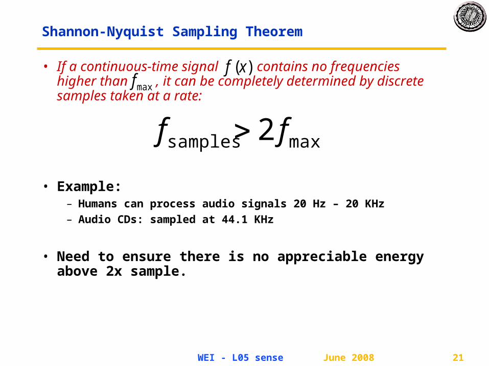
Shannon-Nyquist Sampling Theorem
• If a continuous-time signal contains no frequencies higher than , it can be completely determined by discrete samples taken at a rate:
• Example:– Humans can process audio signals 20 Hz – 20 KHz
– Audio CDs: sampled at 44.1 KHz
• Need to ensure there is no appreciable energy above 2x sample.
)(xfmaxf
maxsamples 2 ff

June 2008WEI - L05 sense 22
Sampling Basics
• Aliasing– Different frequencies are indistinguishable when they are
sampled.
• Condition the input signal using a low-pass filter– Removes high-frequency components
– (a.k.a. anti-aliasing filter)

June 2008WEI - L05 sense 23
Sampling Basics
• Dithering– Quantization errors can result
in large-scale patterns that don’t accurately describe the analog signal
– Introduce random (white) noise to randomize the quantization error.
Direct Samples Dithered Samples

June 2008WEI - L05 sense 24
Analog-to-Digital Basics
• So, how do you convert analog signals to a discrete values?
• A software view:1. Set some control registers :
» Specify where the input is coming from (which pin)
» Specify the range (min and max)
» Specify characteristics of the input signal (settling time)
2. Enable interrupt and set a bit to start a conversion
3. When interrupt occurs, read sample from data register
4. Wait for a sample period
5. Repeat step 1

June 2008WEI - L05 sense 25
Block Diagram (MSP430)

June 2008WEI - L05 sense 26
ADC Features
Texas Instruments MSP430
Atmel
ATmega 1281
Resolution 12 bits 10 bits
Sample Rate 200 ksps 76.9 ksps
Internally Generated Reference Voltage
1.5V, 2.5V, Vcc 1.1V, 2.56V
Single-Ended Inputs 12 16
Differential Inputs 0 14 (4 with gain amp)
Left Justified Option No Yes
Conversion Modes Single, Sequence, Repeated Single, Repeated Sequence
Single, Free Running
Data Buffer 16 samples 1 sample

June 2008WEI - L05 sense 27
ADCs: Resources or Computation
• OS provides a convenient and safe abstraction of physical resources
• Operating systems deal with devices, not ADCs.
• TinyOS has strived to provide uniform, easy-to-use common abstraction of the ADC.
• Should it?
• ADC and how sampling is performed in “on the datapath” of the application.

June 2008WEI - L05 sense 28
ADC Core
• Input– Analog signal
• Output– 12-bit digital value of input
relative to voltage references
• Linear conversion
4095
4095
RRADCin
RR
RinADC
VVNV
VV
VVN
RV
RVinV

June 2008WEI - L05 sense 29
SAR ADC
• SAR = Successive-Approximation-Register– Binary search to find closest digital value

June 2008WEI - L05 sense 30
SAR ADC• SAR = Successive-Approximation-Register
– Binary search to find closest digital value
1 Sample Multiple cycles

June 2008WEI - L05 sense 31
SAR ADC
1 Sample Multiple cycles
June 2008WEI - L05 sense 32
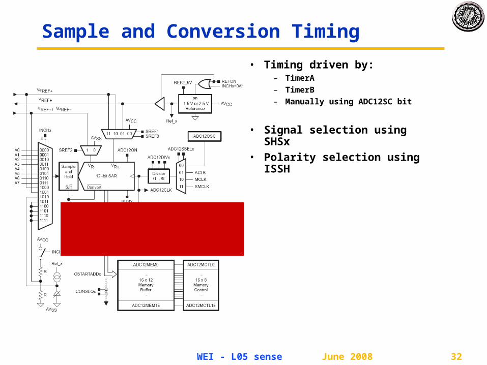
Sample and Conversion Timing
• Timing driven by:– TimerA
– TimerB
– Manually using ADC12SC bit
• Signal selection using SHSx
• Polarity selection using ISSH

June 2008WEI - L05 sense 33
Voltage Reference
• Voltage Reference Generator– 1.5V or 2.5V
– REFON bit in ADCCTL0
– Consumes energy when on
– 17ms settling time
• External references allow arbitrary reference voltage
• Want to sample Vcc, what Vref to use?
Internal External
Vref+ 1.5V, 2.5V, Vcc VeRef+
Vref- AVss VeRef-

June 2008WEI - L05 sense 34
Sample Timing Considerations
• Port 6 inputs default to high impedance
• When sample starts, input is enabled– But capacitance causes a low-pass filter effect
Must wait for the input signal to converge
ns800pF40011.9)kΩ2( Ssample Rt

June 2008WEI - L05 sense 35
Software Configuration
• How it looks in code:
ADC12CTL0 = SHT0_2 | REF1_5V |
REFON | ADC12ON;
ADC12CTL1 = SHP;

June 2008WEI - L05 sense 36
Inputs and Multiplexer
• 12 possible inputs– 8 external pins (Port 6)
– 1 Vref+ (external)
– 1 Vref- (external)
– 1 Thermistor
– 1 Voltage supply
• External pins may function as Digital I/O or ADC.
– P6SEL register
• What sort of a MUX is this?

June 2008WEI - L05 sense 37
Conversion Memory
• 16 sample buffer
• Each buffer configures sample parameters
– Voltage reference
– Input channel
– End-of-sequence
• CSTARTADDx indicates where to write next sample

June 2008WEI - L05 sense 38
Conversion Modes
• Single-Channel Single-Conversion– Single channel sampled and converted once– Must set ENC (Enable Conversion) bit each
time
• Sequence-of-Channels– Sequence of channels sampled and converted
once– Stops when reaching ADC12MCTLx with EOS
bit
• Repeat-Single-Channel– Single channel sampled and converted
continuously– New sample occurs with each trigger
(ADC12SC, TimerA, TimerB)
• Repeat-Sequence-of-Channels– Sequence of channels sampled and converted
repeatedly– Sequence re-starts when reaching
ADC12MCTLx with EOS bit

June 2008WEI - L05 sense 39
Software Configuration
• How it looks in code:
• Configuration
ADC12CTL0 = SHT0_2 | REF1_5V |
REFON | ADC12ON;
ADC12CTL1 = SHP;
ADC12MCTL0 = EOS | SREF_1 |
INCH_11;
• Reading ADC data
m_reading = ADC12MEM0;

June 2008WEI - L05 sense 40
A Software Perspective
command void Read.read() {
ADC12CTL0 = SHT0_2 | REF1_5V | REFON | ADC12ON;
ADC12CTL1 = SHP;
ADC12MCTL0 = EOS | SREF_1 | INCH_11;
call Timer.startOneShot( 17 );
}
event void Timer.fired() {
ADC12CTL0 |= ENC;
ADC12IE = 1;
ADC12CTL0 |= ADC12SC;
}
task void signalReadDone() {
signal Read.readDone( SUCCESS, m_reading );
}
async event void HplSignalAdc12.fired() {
ADC12CTL0 &= ~ENC;
ADC12CTL0 = 0;
ADC12IE = 0;
ADC12IFG = 0;
m_reading = ADC12MEM0;
post signalReadDone();
}

June 2008WEI - L05 sense 41
A Software Perspective
command void Read.read() {
ADC12CTL0 = SHT0_2 | REF1_5V | REFON | ADC12ON;
ADC12CTL1 = SHP;
ADC12MCTL0 = EOS | SREF_1 | INCH_11;
call Timer.startOneShot( 17 );
}
event void Timer.fired() {
ADC12CTL0 |= ENC;
ADC12IE = 1;
ADC12CTL0 |= ADC12SC;
}
task void signalReadDone() {
signal Read.readDone( SUCCESS, m_reading );
}
async event void HplSignalAdc12.fired() {
ADC12CTL0 &= ~ENC;
ADC12CTL0 = 0;
ADC12IE = 0;
ADC12IFG = 0;
m_reading = ADC12MEM0;
post signalReadDone();
}

June 2008WEI - L05 sense 42
A Software Perspective
command void Read.read() {
ADC12CTL0 = SHT0_2 | REF1_5V | REFON | ADC12ON;
ADC12CTL1 = SHP;
ADC12MCTL0 = EOS | SREF_1 | INCH_11;
call Timer.startOneShot( 17 );
}
event void Timer.fired() {
ADC12CTL0 |= ENC;
ADC12IE = 1;
ADC12CTL0 |= ADC12SC;
}
task void signalReadDone() {
signal Read.readDone( SUCCESS, m_reading );
}
async event void HplSignalAdc12.fired() {
ADC12CTL0 &= ~ENC;
ADC12CTL0 = 0;
ADC12IE = 0;
ADC12IFG = 0;
m_reading = ADC12MEM0;
post signalReadDone();
}

June 2008WEI - L05 sense 43
A Software Perspective
command void Read.read() {
ADC12CTL0 = SHT0_2 | REF1_5V | REFON | ADC12ON;
ADC12CTL1 = SHP;
ADC12MCTL0 = EOS | SREF_1 | INCH_11;
call Timer.startOneShot( 17 );
}
event void Timer.fired() {
ADC12CTL0 |= ENC;
ADC12IE = 1;
ADC12CTL0 |= ADC12SC;
}
task void signalReadDone() {
signal Read.readDone( SUCCESS, m_reading );
}
async event void HplSignalAdc12.fired() {
ADC12CTL0 &= ~ENC;
ADC12CTL0 = 0;
ADC12IE = 0;
ADC12IFG = 0;
m_reading = ADC12MEM0;
post signalReadDone();
}

June 2008WEI - L05 sense 44
A Software Perspective
command void Read.read() {
ADC12CTL0 = SHT0_2 | REF1_5V | REFON | ADC12ON;
ADC12CTL1 = SHP;
ADC12MCTL0 = EOS | SREF_1 | INCH_11;
call Timer.startOneShot( 17 );
}
event void Timer.fired() {
ADC12CTL0 |= ENC;
ADC12IE = 1;
ADC12CTL0 |= ADC12SC;
}
task void signalReadDone() {
signal Read.readDone( SUCCESS, m_reading );
}
async event void HplSignalAdc12.fired() {
ADC12CTL0 &= ~ENC;
ADC12CTL0 = 0;
ADC12IE = 0;
ADC12IFG = 0;
m_reading = ADC12MEM0;
post signalReadDone();
}

June 2008WEI - L05 sense 45
MCU
Kernel Driver
Interrupts and Tasks
ADC
Application
command void Read.read() {
ADC12CTL0 = SHT0_2 | REF1_5V | REFON | ADC12ON;
ADC12CTL1 = SHP;
ADC12MCTL0 = EOS | SREF_1 | INCH_11;
call Timer.startOneShot( 17 );
}
event void Timer.fired() {
ADC12CTL0 |= ENC;
ADC12IE = 1;
ADC12CTL0 |= ADC12SC;
}
task void signalReadDone() {
signal Read.readDone( SUCCESS, m_reading );
}
async event void HplSignalAdc12.fired() {
ADC12CTL0 &= ~ENC;
ADC12CTL0 = 0;
ADC12IE = 0;
ADC12IFG = 0;
m_reading = ADC12MEM0;
post signalReadDone();
}

June 2008WEI - L05 sense 46
Interrupts and Tasks
• Tasks are run-to-completion– Used to signal application events
– Break up computation in the application
• Interrupts– Generated by the hardware
– Preempt execution of tasks
• Interrupts and tasks can schedule new tasks
Hardware
Interrupt
Task Task Task
Handler

June 2008WEI - L05 sense 47
TinyOS Generic Components
• Multiple instances of a component
• Type polymorphism
• Compile-time configuration
• All of the above

June 2008WEI - L05 sense 48
TinyOS Parameterized Interface
• Logically related array of interfaces
• Improved code by handling all interfaces collectively
• Compile time sizing across module boundaries
• Basis fo discovery


