Page 1
will be achieved by the
activities listed below:
Priority topics for Task 34
Norms and standards
Analysis – methods
comparison and
developments
Country reports updates/
review of state of the art
Fuels and chemicals from
pyrolysis
In this issue of the newsletter,
you will find short introductory
articles from the national team
leaders from each of the
participating countries
summarizing their particular
efforts in the field and an
overview of the latest Task
meeting including information
about the Round Robin on bio-
oil viscosity and aging.
Welcome to Task 34 By Doug Elliott, Task 34 Leader
Inside this issue
Members 2
Member updates 3-31
Country updates 32-36
Events 36-38
Publications 39
Contact the Editor 40
June 2011
The IEA
Bioenergy Task
34 for Pyrolysis
is hard at work
in the new
triennium from
2010 to 2012.
Current
participants in
the Task are
Canada, Finland,
Germany, the
UK with
leadership
provided by the
USA. This
newsletter is
produced by the Task to
stimulate the interaction of
researchers with commercial
entities in the field of biomass
pyrolysis.
Aims & objectives
The overall objective of Task
34 is to improve the rate of
implementation and success of
fast pyrolysis for fuels and
chemicals by contributing to
the resolution of critical
technical areas and
disseminating relevant
information particularly to
industry and policy makers.
The scope of the Task will be
to monitor, review, and
contribute to the resolution of
issues that will permit more
successful and more rapid
implementation of pyrolysis
technology, including
identification of opportunities
to provide a substantial
contribution to bioenergy. This
IEA Bioenergy Agreement Task 34 Newsletter — PyNe 29 Page 1
Continued on page 2 Published by Aston University
Bioenergy Research Group
ISSN 2040-2759
Page 2
GERMANY Dietrich Meier Johann Heinrich von Thünen-Institut (vTI) Federal Research Institute for Rural Areas, Forestry and Fisheries. Institute of Wood Technology and Wood Biology (HTB), Leuschnerstr. 91, D-21031 Hamburg, GERMANY T: +49 40 73 962517 F: +49 40 73 962599 E: [email protected]
Welcome...continued
Members of IEA Bioenergy Task 34 2010-2012
plus an article regarding lignin
pyrolysis testing at different
temperatures. On pages 28-31
you can find a useful summary
of reviews on biomass
pyrolysis and related aspects.
This electronic newsletter is
published twice a year.
Comments and suggestions for
future input are invited: please
contact the editor, Irene
Watkinson at
[email protected] .
DC Elliott
Battelle PNNL
P.O. Box 999, Richland
Washington 99352, USA
Tel: +1 509 375 2248
Fax: +1 509 372 4732
Email: [email protected]
CANADA Fernando Preto Bioenergy Systems, CanmetENERGY, Natural Resources Canada, 1 Haanel Drive, Ottawa, CANADA K1A 1M1 T: +1 613 996 5589 E: [email protected]
USA Doug Elliott Battelle PNNL 902 Battelle Boulevard P.O. Box 999 Richland Washington, 99352 USA T: +1 509 375 2248 F: +1 509 372 4732 E: [email protected]
FINLAND Anja Oasmaa VTT Technical Research Centre of Finland, Liquid Biofuels Biologinkuja 3-5, P.O. Box 1000, Espoo, FIN-02044 VTT, FINLAND T: +358 20 722 5594 F: +358 20 722 7048 E: [email protected]
UK Tony Bridgwater Aston University Bioenergy Research Group School of Engineering and Applied Science, Birmingham B4 7ET, UK T: +44 121 204 3381 F: +44 121 204 3680 E: [email protected]
IEA Bioenergy Agreement Task 34 Newsletter — PyNe 29 Page 2
Doug Elliott
Task 34 Leader
Also, there are several articles
from around the world
describing the latest
developments in fast pyrolysis
including work in Finland at
Åbo Akademi University and at
VTT. From the USA we have a
contribution from Utah State
University, an overview of the
new catalytic pyrolysis (in
hydrogen) technology from the
Gas Technology Institute
(GTI), plus news about a USA/
South African collaboration.
There‘s also an article from
Envergent Technologies in
Canada, and an update from
the Energy research Centre of
the Netherlands about IEA
Bioenergy Task 42. From the
UK, there‘s an overview of a
biorefinery chain methodology,
Page 3
UOP, and more than 25 years
of biomass conversion
technology experience from
Ensyn Corp.
Use of the technology will help
Crane, which has been the
provider of currency paper to
the U.S. Treasury for more
than 130 years, stabilize
energy costs and remain a
competitive supplier to the US
Government. Once approved,
the project has the potential to
bring nearly 100 new green
jobs to the region.
In addition to Envergent
Technologies, Crane & Co. is
working with Berkshire
Renewable Power and
ReEnergy Holdings for
implementation of the project.
All the partners involved
hosted a demonstration of the
process at Crane & Co‘s.
headquarters in Dalton,
Massachusetts on February
24th.
Envergent Technologies and Ensyn demonstrate renewable liquid fuel for heat
and power at Crane & Co
In February 2011, Envergent
Technologies, a Honeywell
company, announced that its
RTP™ technology will be used
by Crane & Co. to convert
biomass feedstock into a
renewable fuel oil to heat and
power the Crane
Massachusetts facility where it
produces paper for USA
currency.
Envergent‘s RTP™ (Rapid
Thermal Processing)
Technology will convert local
forest residue into a clean-
burning, nearly carbon-neutral
liquid biofuel that can be used
as a direct replacement for
petroleum-based fuel in
today‘s burners and
generators.
Envergent Technologies is a
joint venture of Honeywell‘s
UOP and Ensyn Corporation. It
combines nearly 100 years of
refining and process
technology development from
IEA Bioenergy Agreement Task 34 Newsletter — PyNe 29 Page 3
―It will serve as an excellent model for other
businesses across the nation and around the world.‖
David Cepla
Managing Director
Envergent
Technologies
Continued on page 4
An update from Stefan Müller of Ensyn Technologies
Page 4
ambient pressure to
generate high yields of a
liquid biofuel. The fuel
can be burned in
industrial burners and
furnaces for heat, or to
power electric
generators. RTP is
currently in use in seven
commercial biomass
processing plants in the
USA and Canada.
Wholly owned by
Honeywell, UOP
equipment can be found
in the majority of
petroleum refineries
worldwide. 60% of the
world‘s gasoline is
produced in UOP
equipment and UOP
engineers have
generated thousands of
patents covering process
technology and
equipment design.
In 2006, UOP formed its
Renewable Energy &
Chemicals division to develop
ways to efficiently and
profitably convert biological
feedstocks into more valuable,
environmentally friendly
biofuels and chemicals.
This powerful partnership
combines Ensyn‘s RTP
technology that converts wood
biomass to high yields of light
liquid with UOP‘s technology to
provide engineering and
support for RTP projects
worldwide, and to upgrade RTP
fuels to transportation fuels.
Ensyn and Envergent have
announced four RTP projects
to date, including projects in
Malaysia, Italy, Canada
(Alberta) and this initiative in
Massachusetts.
Learn more about Ensyn at
www.ensyn.com and about
Envergent Technologies at
www.envergenttech.com.
Contact:
Stefan Müller
Ensyn Technologies Inc.
2 Gurdwara Road, Suite 210
Ottawa, Ontario K2E 1A2
Canada
T: +1 604 945 6673
E: [email protected]
www.ensyn.com
Envergent Technologies and Ensyn demonstrate renewable liquid fuel for heat
and power at Crane & Co...continued ―For more than two centuries,
Crane & Co. has worked to
innovate at the highest level
while keeping our
environmental impact at a
minimum,‖ said Charles
Kittredge, CEO of Crane & Co.
―With the addition of this
technology from Envergent
and the participation of
ReEnergy Holdings and
Berkshire Renewable Power,
we can better fulfil this
promise with a reliable,
sustainable fuel source that
keeps us competitive in the
marketplace, delivers a
superior-quality product to our
customers and stimulates our
local economy.‖
―To have one of the oldest and
most important companies in
American history take such a
leading position by using
renewable fuel oil from RTP for
its energy needs speaks of the
incredible benefits this
technology provides,‖ said
David Cepla, managing
director for Envergent
Technologies. ―The success of
Crane & Co. and its local
partners with RTP will serve as
an excellent model for other
businesses across the nation
and around the world.‖
Because the forest residues to
be converted into the
renewable liquid fuel will come
from the region, Crane‘s use of
renewable power can be
thought of as an extension of
a larger regional initiative
called ―Berkshire Grown,‖
which aims to stimulate the
area by creating, growing and
buying all products locally.
RTP technology works by
rapidly heating biomass – in
this case, forest residue - at
IEA Bioenergy Agreement Task 34 Newsletter — PyNe 29 Page 4
Page 5
of CRIPS is also under
construction at the ARS lab
near Philadelphia to study the
hydrodynamics of the system.
Professor Mike Heydenrych is
supported in part by the Pulp
& Paper Manufacturing
Association of South Africa
(PAMSA), which has provided
funds and sponsored
graduated students (1 PhD
and 3 MS) to carry out
pyrolysis studies under his
guidance. The ARS project is
part of research funded by
USDA and entitled ―Distributed
scale pyrolysis of agricultural
biomass for production of
refinable crude bio-oil and
valuable co-products,‖ for
which Kwesi is the lead
scientist. http://
www.ars.usda.gov/main/
site_main.htm?modecode=19-
35-57-00
Contact:
Dr. Akwasi Boateng
Eastern Regional Research
Center
Agricultural Research Service
USDA, 600 E. Mermaid Lane
Wyndmoor PA 19038
USA
T: +1 215 233 6493
E: [email protected] .
gov
www.ars.usda.gov/naa/errc
USA - South African Collaboration on Combustion-Reduction Integrated
Pyrolysis System (CRIP) The Agricultural Research
Service (ARS), the principal
intramural research arm of the
United States Department of
Agriculture (USDA), and
University of Pretoria, South
Africa, have entered into a
Non-funded Cooperative
Research Agreement (NFCA)
for two years (ending July 31st
2012) to develop an energy
self-sufficient pyrolysis system
for the production of
renewable bio-crude.
The collaboration is to explore
some existing twin-bed
gasifier designs in South Africa
for catalytic pyrolysis to
produce fuels and chemicals.
Dr. A.A. (Kwesi) Boateng of
ARS, who has demonstrated
experience in the design of
similar systems, and Professor
Mike Heydenrych of the
Department of Chemical
Engineering at University of
Pretoria (UP), with synergic
experiences, are the
collaborators on this project.
In a visit to UP in July through
to August 2010, Kwesi and
Mike completed a design for a
20 kg/hr Combustion-
Reduction Integrated Pyrolysis
System (CRIPS) which is
currently under construction in
South Africa, and is expected
to be operational in the
summer of 2011. In the
meantime, a cold flow model
IEA Bioenergy Agreement Task 34 Newsletter — PyNe 29 Page 5
Akwasi Boateng (above) of the United States Department of Agriculture (USDA) provides an overview of a joint project with
Mike Heydenrych (below) of the University of Pretoria in South Africa
Page 6
Task 34 Pyrolysis meeting Hamburg, Germany April 6-8, 2011
IEA Bioenergy Agreement Task 34 Newsletter — PyNe 29 Page 6
-oil samples were being
distributed by CanMet with
the expectation that the
results will be received by
the time this newsletter is
published in June.
The group also toured the
biomass pyrolysis
laboratories of Dr. Meier at
the Johann Heinrich von
Thünen-Institut for Wood
Technology and Biology at
the University of
Hamburg. Most of the
members also took part in a
study tour to the PyTec
ablative fast pyrolysis pilot
plant.
The next meeting of the
Task is scheduled for
October 3-4, 2011, in
Richland, Washington, USA,
including a tour of the Pacific
Northwest National
Laboratory pyrolysis and bio
-oil upgrading laboratories.
Doug Elliott
Task 34 Leader
Doug Elliott,
Task 34 Leader
gives an update
on the recent
Pyrolysis
meeting
Figure 1: Left to right: Steffen Krzack, Daniel Nowakowski, Irene Watkinson,
Paul de Wild, Anja Oasmaa, Fernando Preto, Dietrich Meier, Doug Elliott, Tony
Bridgwater.
All National Team Leaders
(NTLs) were present for the
recent meeting of the Task 34
on Pyrolysis. The agenda items
included country reports and
formulation of a plan to publish
the information; norms and
standards developments and
discussion of publication efforts
for information on sulfur/
nitrogen analysis and bio-oil
transport and infrastructure
issues, as well as an improved
Material Safety Data Sheet
(MSDS) for bio-oil; and the
status of the Round Robin on
bio-oil viscosity and thermal
stability.
An important outcome of the
meeting was the organization
of an extension to the Round
Robin analysis of bio-oil
samples for viscosity and
thermal aging to extend a
portion at some of the study at
some of the labs for a full
year. The list of participants in
the initial Round Robin includes
15 laboratories in the five
participating countries. The bio
―An important
outcome of
the meeting
was the
organization
of an
extension to
the Round
Robin analysis
of bio-oil
samples.‖
Page 7
The greenhouse gas emission saving of
logging residue-based pyrolysis oil
IEA Bioenergy Agreement Task 34 Newsletter — PyNe 29 Page 7
―The emissions from changes in soil carbon stocks, due to raw material harvesting, is one of the most critical issues to be dealt with in the use of logging residues.‖
Continued on page 8
The greenhouse gas emission
saving of pyrolysis oil was
calculated by following the
method provided in the
European Union‘s (EU)
Renewable Energy Directive
(RED) [1]. The RED establishes
a mandatory target to increase
the use of renewable energy
sources in final energy
consumption to a level of 20%,
and in transportation to a level
of 10%, within the EU by 2020.
In addition, the RED introduces
the first ever mandated method
to calculate the greenhouse gas
(GHG) emissions of biofuels and
bioliquids, and the GHG
emission reduction compared
with fossil fuels. The emission
reductions should be at least
35% for biofuels and other
bioliquids produced before the
end of 2016. From the
beginning of 2017, the target
increases to 50% and from the
beginning of 2018 to 60% for
biofuel production installations
where production begins after
1st January 2017. The above
mentioned emission reduction
targets have to be achieved in
order for biofuels and bioliquids
to be accounted for renewable
energy targets and to benefit
from subsidies.
The pyrolysis oil was assumed
to be produced in a fast
pyrolysis reactor integrated with
a combined heat and power
production (CHP) plant. The
CHP plant provides heat for the
district and the pyrolysis
reactor, and power to the
electric grid. The boiler is
fuelled with logging residue
chips and milled peat, which is a
typical fuel in co-firing in
Finland. The share of logging
residue chips was varied
between 0% and 100% in order
to assess how boiler fuels affect
GHG emissions of pyrolysis oil.
In addition, a case study where
A synopsis from
Reetta Sorsa of
VTT Technical
Research Centre
of Finland
the CHP plant is only fuelled
by logging residues was
carried out. The fuel capacity
of the CHP plant was
calculated to be 96 MW, and
the electricity and heat
outputs correspond to 27 MW
and 54 MW respectively [2].
Pyrolysis oil was assumed to
replace heavy fuel oil in heat
production.
The raw material for pyrolysis
oil was assumed to be logging
residues from boreal Scots
pine and spruce forests. The
emissions from changes in soil
carbon stocks, due to raw
material harvesting, is one of
the most critical issues to be
dealt with in the use of logging
residues. When residues are
harvested, the soil carbon
stocks reduce compared to the
reference situation (the
decomposition of logging
residues at the site). When
logging residues are
combusted carbon is released
instantly. If logging residues
are left on the site, the carbon
would still have been released
to the atmosphere through
decomposition but over a
much longer period of time.
The difference in carbon
contents released to the
atmosphere between
bioenergy utilisation and
reference situation can be
considered as indirect
emissions [3]. To find out the
effect of these emissions,
three different scenarios were
calculated. Firstly, we
excluded soil carbon changes.
Secondly, we calculated them
using 20 and 100 year time
frames.
The system boundaries were
set in accordance with the
framework given in the RED.
Page 8
However, the RED
leaves room for
setting system
boundaries and select
parameters differently.
All the possible
interpretations were
considered. With the
information provided
in the RED, we could
not determine whether
or not logging residues
should be classified as
‗residues or wastes‘.
Thus, the system
boundary was divided
in two parts (Figure
1). If raw materials
are classified as
‗residues or wastes‘
they are considered to
have zero lifecycle
GHG emissions up to
the collection of raw
materials. The RED
also determines that
the unit of analysis for
the purposes of
allocation is the
refinery if the fuels are
produced in a refinery
[1].
However, according to
the particular
definition it is unclear
whether the pyrolysis
reactor and the CHP
plant should be
assumed to be two
separate units or one
combined refinery.
Therefore, we
considered both
options. Case 1 covers
two separate units,
and case 2, one
combined refinery.
In-house data of VTT
Technical Research
Centre of Finland was
IEA Bioenergy Agreement Task 34 Newsletter — PyNe 29 Page 8
The greenhouse gas emission saving of logging residue-based pyrolysis
oil...continued
Figure 1: System boundary according to the Renewable Energy Directive (RED) ● denotes allocation
Continued on page 9
Page 9
used for the
process
parameters of
the pyrolysis
reactor. All the
other
parameters
were gathered
from literature
sources. Firstly,
we determined
the best
estimates for
each of these
parameters.
Secondly, we
determined confidential levels
and probability distributions
for each parameter. The
uncertainty analysis was then
carried out using a Monte
Carlo simulation [4]. When
calculating the GHG emission
reductions, heavy fuel oil in
heat production was used as a
fossil comparator. The
contribution of each variable to
the emission saving result was
measured using Spearman‘s
rank correlation.
Table 1 shows the probabilities
of achieving 35%, 50%, and
60% emission saving.
Consideration of the pyrolysis
reactor and the CHP plant as
two separate units or one
combined refinery has a
significant impact on the
results. However, the
difference gets lower when the
proportion of peat in the CHP
decreases. In addition,
consideration of changes in
soil carbon balances has a
remarkable influence on the
results. A 60% emission
reduction target is achieved if
changes in soil carbon
balances are excluded except
in case 2a in which the
probability of achieving the
60% emission saving remains
low. This results from the
system boundary setting, in
which significant amounts of
emissions from the CHP plant
(based on the energy content
of the products), are
attributed to pyrolysis oil.
Generally, the results depend
significantly on the selection of
parameter set and
interpretation of the definitions
provided in the RED to set the
system boundary for the
pyrolysis reactor and the CHP
plant.
Acknowledgements
Reetta Sorsa‘s masters thesis
was carried out as a part of
the TEKES project: ―Integrated
utilisation chains of second
generation pyrolysis‖.
Acknowledgements go to
TEKES, Fortum, Lassila &
Tikanoja, Metso Power, UPM
and VTT for funding, as well as
Sampo Soimakallio, Yrjö
Solantausta and Esa
Vakkilainen for guidance with
her thesis.
Contact:
Reetta Sorsa
VTT Technical Research Centre
of Finland
Climate Change Mitigation
P.O. Box 1000, 02044 VTT
Finland
T: +358 20 722 6584
E: [email protected]
www.vtt.fi
References
[1] Directive 2009/28/EC on the
European Parliament and of the
Council of April 2009 on the
promotion of the use of energy from
renewable sources and amending
and subsequently repealing
Directives 2001/77/EC and
2003/30/EC. Official Journal of the
European Union, L140, 16–62.
[2] Sorsa, R., 2011. The life cycle
assessment of pyrolysis oil derived
from logging residues (in Finnish).
Master's thesis. Lappeenranta
University of Technology. 109 p. +
app.11 p.
[3] Repo, A., Tuomi, M., Liski, J., 2010.
Indirect carbon dioxide emissions
from producing bioenergy from
forest harvest residues. GCB
Bioenergy, 2, 107–115.
[4] Barkema, G.. T., Newman, M.,
1999. Monte Carlo Methods in
Statistical Physics. Oxford University
Press 1999.
IEA Bioenergy Agreement Task 34 Newsletter — PyNe 29 Page 9
The greenhouse gas emission saving of logging residue-based pyrolysis
oil...continued
RED
Bio-CHP
1a
[%]
1b
[%]
1c
[%]
2a
[%]
2b
[%]
2c
[%]
1a
[%]
1b
[%]
1c
[%]
2a
[%]
2b
[%]
2c
[%]
35% 100 100 99 48 38 4 100 100 100 100 100 78
50% 100 100 51 30 19 0 100 100 78 100 100 17
60% 100 100 6 18 10 0 100 100 23 100 100 1
Table 1 The probabilities of achieving 35%, 50%, and 60% emission savings. ―1‖ refers to case where pyrolysis reactor and CHP plant were assumed to be two separate units and ―2‖ refers to case where pyrolysis reactor and CHP plant were assumed to be one combined unit. Letters ―a‖, ―b‖, and ―c‖ refer to the consideration of changes in soil carbon balances (a=excluded, b=100-year time frame, c= 20-year time frame). Bio-CHP refers to the case where the boiler is fuelled by logging residue chips.
Page 10
The Gas Technology Institute
(GTI) in the States is
developing a new process
called integrated
hydropyrolysis and
hydroconversion (IH2) to
directly produce gasoline, jet
and diesel hydrocarbon blend
stock from biomass.
The key to the process is the
first stage catalytic
hydropyrolysis step where
biomass is converted to low
TAN hydrocarbons in a
fluidized bed of catalyst under
hydrogen pressure of 20 to 35
bar and temperatures of 370
to 475°C. Catalytic
hydropyrolysis removes more
than 90% of the biomass
oxygen as water and COX,
while minimizing undesirable
acid-catalyzed polymerization,
aromatization, and coking
reactions which occur during
standard fast pyrolysis. The
integrated hydroconversion
step then produces a final IH2
product with less than 1%
oxygen and less than 1 TAN.
Furthermore, catalytic
hydropyrolysis is exothermic
Direct production of gasoline and diesel from biomass using integrated hydropyrolysis and hydroconversion (IH2)
because oxygen is removed
and hydrogen is added to the
hydrocarbon structure, which
eliminates the need for
recirculation of the solid heat
carrier which is required in
pyrolysis.
Another inherent advantage of
catalytic hydropyrolysis is that
a hydrocarbon product is
directly produced which can be
easily upgraded in an
integrated hydrotreating
reactor to stabilize and polish
the product.
A unique feature of this
process is that all the
hydrogen required for the IH2
process is produced by
reforming the C1-C3 products
so no supplementary hydrogen
is required, allowing greater
flexibility with respect to unit
location. The IH2 integrated
process schematic is shown in
Figure 1.
Initial economic analyses
suggest that the IH2 process
IEA Bioenergy Agreement Task 34 Newsletter — PyNe 29 Page 10
Continued on page 11
Terry Marker provides an insight into new processes being developed at the Gas Technology Institute in USA
―IH2 makes high quality hydrocarbon fuels from biomass
cheaply and directly. The key to commercial success is demonstrating catalyst stability in our
new continuous pilot plant.‖
Figure 1: IH2 system schematic, showing overall process flow
Page 11
has excellent economics and
90% greenhouse gas
reduction, and is an
improvement compared to
pyrolysis, plus upgrading for
producing transportation fuels
from biomass.
To achieve good separation of
biomass and catalyst in
catalytic hydropyrolysis, the
catalyst is a larger diameter
and denser than the biomass.
The mechanism of first stage
catalyst-char separation is
shown in Figure 2.
Initial experiments have been
conducted in a small scale mini
bench unit (MBU) which feeds
1 lb/hr of biomass over a
period of 3-6 hours. A drawing
of the MBU is shown in Figure
3.
Yields and product quality data
from MBU tests of
hydropyrolysis and integrated
hydropyrolysis, and
hydroconversion using various
Direct production of gasoline and diesel from biomass using integrated hydropyrolysis and hydroconversion (IH2)
...continued
wood feeds is shown in Table
1.
The heart of the catalytic
hydropyrolysis step is the
catalyst. CRI/Criterion supplies
the proprietary catalysts used
in both the first and second
IH2 stages. CRI/Criterion is
helping to commercialize the
IH2 technology and have
exclusive global
sublicensing
rights when it
has been fully
demonstrated.
Based on the
data obtained to
date, the IH2
process appears
to be a highly
advantaged
solution to
producing high
quality
hydrocarbon fuel
blendstocks
cheaply and
directly from
lignocellulosic Figure 2: Mechanism of char-catalyst separation
IEA Bioenergy Agreement Task 34 Newsletter — PyNe 29 Page 11
feeds. But to demonstrate that
the process is commercially
viable, long term catalyst
stability and attrition tests
must be completed. In order
to accomplish this goal, GTI is
currently building a 50 kg/day
IH2 pilot plant working with
Zeton. This pilot plant should
be delivered by September
2011 and operational by the
end of the year. Discussions
with various parties regarding
larger, demonstration scale
facilities are well advanced.
A picture of the partially
constructed skid is shown in
Figure 4.
The IH2 project was funded
through the U.S. Department
Of Energy (DOE) project DE-
EE0002873. Other IH2 DOE
project partners include CRI/
Criterion, Cargill, Johnson
Timber, Aquaflow, Blue Marble
Energy, NREL and MTU.
Continued on page 12
Table 1: Hydropyrolysis and IH2 experimental yields – wt% MAF
Hydropyrolysis IH2
% C4+ Liquid 27 26.5
% O in C4+ <3 <1
TAN in C4+ <2 <1
C4+ % Gasoline 53-75 53-75
C4+ % Diesel 25-47 25-47
% Char 13 13
% COx 17 17
% C1-C3 14 14
% Water 33 33.5
% H2 uptake 3-4 3-4
Page 12
Direct production of gasoline and diesel from biomass using integrated hydropyrolysis and hydroconversion (IH2)
...continued
IEA Bioenergy Agreement Task 34 Newsletter — PyNe 29 Page 12
Figure 4: GTI’s new 50 kg/day IH2 pilot plant under construction
Figure 3: GTI’s IH2 pilot plant
Contact:
Terry Marker
Gas Technology Institute
1700 S Mount Prospect Road
Des Plaines Il 60018
USA
T: +1 847 768 0500
E: terry.marker@
gastechnology .org
www.gastechnology.org
Page 13
the zeolite‘s acidity [1] and
structure [2] was investigated.
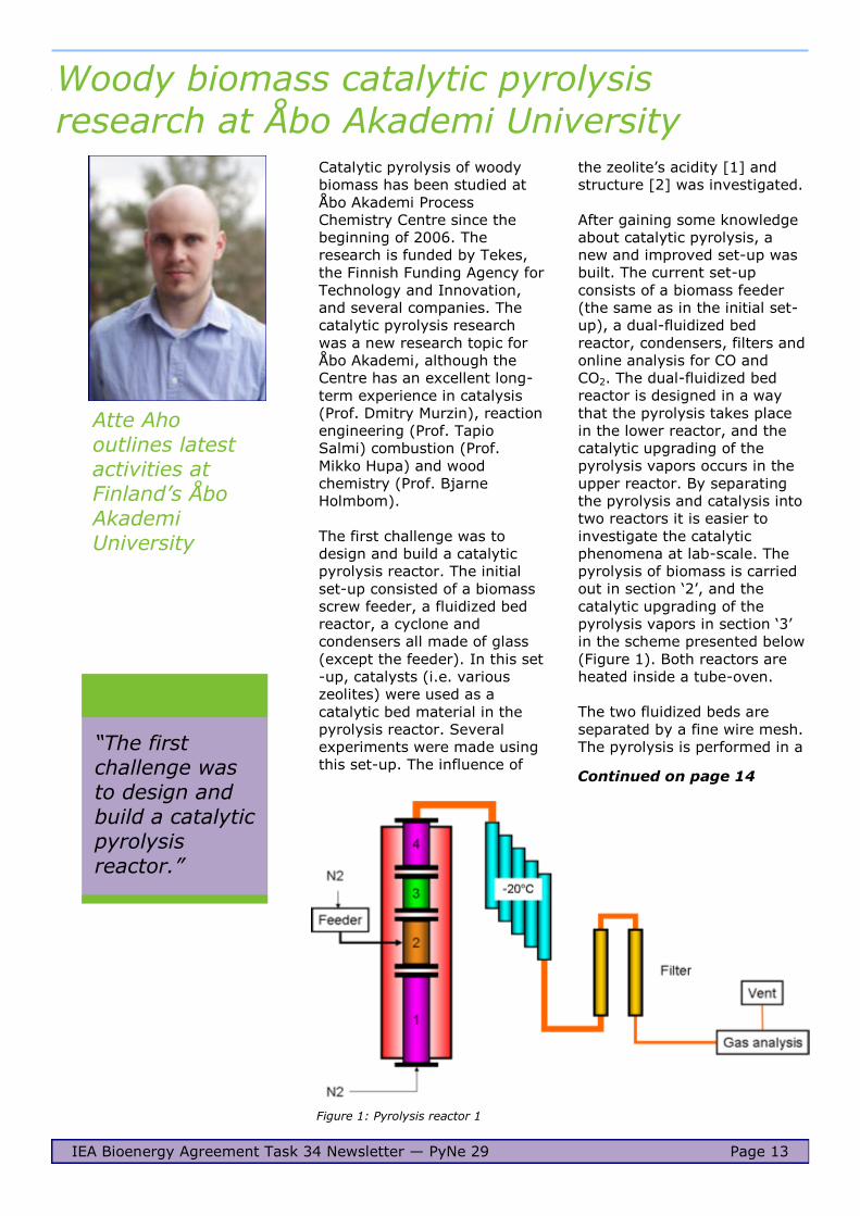
After gaining some knowledge
about catalytic pyrolysis, a
new and improved set-up was
built. The current set-up
consists of a biomass feeder
(the same as in the initial set-
up), a dual-fluidized bed
reactor, condensers, filters and
online analysis for CO and
CO2. The dual-fluidized bed
reactor is designed in a way
that the pyrolysis takes place
in the lower reactor, and the
catalytic upgrading of the
pyrolysis vapors occurs in the
upper reactor. By separating
the pyrolysis and catalysis into
two reactors it is easier to
investigate the catalytic
phenomena at lab-scale. The
pyrolysis of biomass is carried
out in section ‗2‘, and the
catalytic upgrading of the
pyrolysis vapors in section ‗3‘
in the scheme presented below
(Figure 1). Both reactors are
heated inside a tube-oven.
The two fluidized beds are
separated by a fine wire mesh.
The pyrolysis is performed in a
Woody biomass catalytic pyrolysis
research at Åbo Akademi University
IEA Bioenergy Agreement Task 34 Newsletter — PyNe 29 Page 13
Catalytic pyrolysis of woody
biomass has been studied at
Åbo Akademi Process
Chemistry Centre since the
beginning of 2006. The
research is funded by Tekes,
the Finnish Funding Agency for
Technology and Innovation,
and several companies. The
catalytic pyrolysis research
was a new research topic for
Åbo Akademi, although the
Centre has an excellent long-
term experience in catalysis
(Prof. Dmitry Murzin), reaction
engineering (Prof. Tapio
Salmi) combustion (Prof.
Mikko Hupa) and wood
chemistry (Prof. Bjarne
Holmbom).
The first challenge was to
design and build a catalytic
pyrolysis reactor. The initial
set-up consisted of a biomass
screw feeder, a fluidized bed
reactor, a cyclone and
condensers all made of glass
(except the feeder). In this set
-up, catalysts (i.e. various
zeolites) were used as a
catalytic bed material in the
pyrolysis reactor. Several
experiments were made using
this set-up. The influence of
Figure 1: Pyrolysis reactor 1
Atte Aho outlines latest activities at Finland’s Åbo Akademi University
―The first challenge was to design and build a catalytic pyrolysis
reactor.‖
Continued on page 14
Page 14
semi-continuous mode, i.e. by
continuous feeding of the
biomass but without removal
of the formed char. The
catalytic upgrading reactor
operates in a continuous mode
during the experiments, where
the pyrolysis vapors formed in
the lower reactor flows
through the fluidized catalyst
bed.
The major challenge in both
set-ups has been the
separation of the pyrolysis
vapors. Currently three types
of condensers are used,
namely a jacketed condenser
and two types of spiral
condensers, all operated at
-20°C. After the condensers,
the remaining vapors/aerosols
are led through two ~25 cm
long cotton filled tubes. The
mass balance closure, 85–95
wt-%, can be considered as a
good one when taking into
account the extremely small
amount of biomass used in the
experiments. During a typical
run with this set-up only about
10–20g of biomass is fed to
the pyrolysis reactor.
Most of our pyrolysis research
has been made with pine wood
as the raw material. In
addition, the most abundant
polymers in pine wood,
namely cellulose [3],
galactoglucomannan
(hemicellulose) [3] and lignin
[4], have been tested
separately. The feeding of
pure compounds to the reactor
was quite challenging,
therefore different
modifications to the set-up
and the raw material had to be
made in order to successfully
study them.
Several different catalysts
have been tested in the dual-
fluidized bed reactor. As in the
first set-up, the influence of
different acidities [5,6] and
structures [5-8] has been
investigated. Moreover,
different zeolite structures
have been modified with
metals [7] and furthermore,
an attempt to increase the
mechanical strength of the
catalyst particles was
undertaken by using bentonite
Woody biomass catalytic pyrolysis
research at Åbo Akademi University
...continued
IEA Bioenergy Agreement Task 34 Newsletter — PyNe 29 Page 14
Char Coke Organic
phase
Water CO CO2 Mass
balance
Non-catalytic Pine 400oC 23.5 0.0 51.5 8.1 3.0 6.3 92.4
Pine 450oC 17.6 0.0 51.7 7.8 6.0 7.3 90.4
Pine 500oC 14.7 0.0 48.7 8.4 7.7 5.8 85.3
Cellulose 450oC 14.5 0.0 55.1 7.0 2.9 5.7 85.2
Catalytic pine H-Beta-25* 23.5 7.6 20.8 12.7 8.3 7.1 80.0
H-ZSM-5-80* 21.1 4.9 27.6 16.6 10.2 7.0 87.4
H-FER-20* 20.8 1.5 43.8 7.8 3.5 5.3 82.7
Figure 2: Pyrolysis reactor 2 Continued on page 15
*The numbers after the zeolite structure name corresponds to the SiO2/Al2O3 molar ratio
Table 1: Results of several different catalysts tested in the dual-fluidized bed reactor
Page 15
as a binder [8]. Some selected
results are given in Table 1.
It is well known that the char
yield decreases when the
pyrolysis reaction temperature
is increased, as noticed in the
table. However, in our set-up
the bio-oil yield (organic phase
+ water) is fairly constant in
the tested temperature range.
Among the tested raw
materials, cellulose produces
the highest organic yield.
The aim in the catalytic
pyrolysis is to deoxygenate the
pyrolysis vapors. Usually this
occurs through
decarbonylation, producing
more CO, and dehydration,
producing more water. This
can be achieved by selecting a
zeolite, or another catalyst,
with pore sizes large enough
to accommodate the pyrolysis
vapors. H‑FER-20 has smaller
pores than Beta and ZSM-5,
and as seen in the table the
water and CO yields are
similar to the non-catalytic
pyrolysis. A drawback in the
use of zeolites in the
upgrading is the loss of
organics due to coking of the
catalyst.
More results can be found in
papers written by Åbo
Akademi University.
References
[1] Aho A, Kumar N, Eränen K,
Salmi T, Hupa M, Murzin D Yu, Catalytic pyrolysis of biomass
in a fluidized bed reactor:
influence of the acidity of H-
Beta zeolite, IChemE, part B,
Process Safety and
Environmental Protection,
2007, 85, 473-480
[2] Aho A, Kumar N, Eränen K,
Salmi T, Hupa M, Murzin D Yu,
Catalytic pyrolysis of woody biomass in a fluidized bed
reactor: influence of the
zeolite structure, Fuel, 2008,
87, 2493-2501 [3] Aho A, Kumar N, Eränen K,
Holmbom B, Hupa M, Salmi T,
Murzin D Yu, Pyrolysis of
softwood carbohydrates in a
fluidized bed reactor,
International Journal of
Molecular Sciences, 2008, 9,
1665-1675
[4] Lindén I, Aho A, DeMartini N, Brink A, Murzin D, Hupa M,
Mikkola J-P, Pyrolysis of lignin
in a laboratory fluidized bed
reactor, Proceedings of the
Swedish-Finnish Flame Days
2011
[5] Aho A, Käldström M, Fardim P,
Kumar N, Eränen K, Salmi T,
Holmbom B, Hupa M, Murzin D
Yu, Catalytic deoxygenation of cellulose pyrolysis vapours
over mesoporous materials,
Cellulose Chemistry and
Technology, 2010, 44, 89-96
[6] Aho A, Kumar N, Eränen K,
Salmi T, Holmbom B,
Backman P, Hupa M and
Murzin D Yu, Catalytic
pyrolysis of woody biomass, Biofuels, 2010, 1, 263-275
[7] Aho A, Kumar N, Eränen K,
Salmi T, Holmbom B, Hupa M,
Murzin D Yu, Catalytic
upgrading of woody biomass
derived pyrolysis vapours over
iron modified zeolites in a dual
-fluidized bed reactor, Fuel, 2010, 89, 1992-2000
[8] Aho A, Kumar N, Eränen K,
Hupa M, Salmi T and Murzin D
Yu, Zeolite-bentonite hybrid
catalysts for the pyrolysis of
woody biomass, Studies in
Surface Science and Catalysis,
2008, 174B, 1069-1074
Contact:
Atte Aho
Åbo Akademi University
Tuomiokirkontori 3
FI-20500 Turku
Finland
T: +358 2 215 31
E: [email protected]
www.abo.fi
Woody biomass catalytic pyrolysis
research at Åbo Akademi University ...continued
IEA Bioenergy Agreement Task 34 Newsletter — PyNe 29 Page 15
Page 16
The major objective of Task 42
- Biorefineries is to assess the
worldwide position and
potential of the biorefinery
concept. Presently, much
attention is focused on a
workable biorefinery
classification system, as well
as an inventory of the most
promising bio-based
chemicals. Production of
chemicals from lignin is seen
as a long term opportunity
that depends on the
(increasing) availability of high
-purity lignin, e.g. as a by-
product from lignocellulosic
biorefineries for transportation
fuels such as bioethanol.
An important activity of Task
34 – Pyrolysis of biomass is to
focus on the resolution of
technical issues to aid
commercial implementation of
fast pyrolysis, e.g. within the
framework of a biorefinery. As
a co-operation between Task
34 and 42, a case study is
conducted on lignin
valorisation by pyrolysis to
facilitate lignocellulosic
IEA Bioenergy Tasks 34 and 42: co-operation on a lignin pyrolysis biorefinery
biorefineries.
The main goal of the study is a
limited techno-economic
evaluation of lignin
valorisation to gas, phenols
and biochar via fluidised-bed
pyrolysis technology.
Currently, the lignin study is
based on lab-scale
experimental data and on the
results of a market survey for
lignin-derived pyrolysis
products. Preliminary results
indicate that the annual
revenue of a typical 100–
1000 t/d multiproduct
lignocellulosic biorefinery
producing bioethanol and co-
products can be increased
significantly by implementing
the pyrolysis of lignin.
Approach/assumptions
Economic margin analysis and
preliminary capital and
operational expenses have
been estimated for a lignin
pyrolysis plant that processes
300,000 ton/year of lignin (>
95% pure) to gas, lignin
pyrolysis oil and char. It is
assumed that the lignin
production/separation/
purification costs in the
biorefinery are €500 per dry
ton of lignin.
The pyrolysis reactor is
modelled as a typical
petrochemical Fluid Catalytic
Cracking (FCC) unit including
primary downstream
treatment, such as collection
of the oil and char. Further
downstream processing is also
modelled according to
petrochemical analogs such as
vacuum distillation to split the
IEA Bioenergy Agreement Task 34 Newsletter — PyNe 29 Page 16
Continued on page 17
Update from
Paul de Wild of the Energy research Centre of the Netherlands (ECN)
Figure 1: Simple flow scheme of the pyrolytic valorization of lignin into monomeric phenols, oligomeric phenols and biochar
Page 17
monomerics and oligomerics,
visbreaking and coking units
for the upgrading of the heavy
oil fraction and the char and
distillation/solvent extraction
to separate individual phenols.
The lignin pyrolysis oil is
comprised of a monomeric and
oligomeric phenolics fraction.
The lignin pyrolysis gas mainly
consists of CO, CO2, methane
and minor amounts of other
hydrocarbons, such as
ethylene. Typical yields (based
on the dry lignin intake) are
15% gas, 35% char and 50%
oil. Approximately 20% of the
oil is made up by a great
variety of monomeric phenols,
with guaiacols and syringols
being the most abundant
ones. Another 40% of the oil
consists of a tarry fraction,
presumably oligomeric
substances of phenolic origin.
The remaining 40% is mainly
water with minor amounts of
low-boiling components, such
as methanol and acetic acid.
Four product driven cases
were distinguished: 1) all
products to fuel, 2) use
pyrolytic lignin oil as such, 3)
separate pyrolytic lignin oil in
monomers and oligomers, 4)
separate pyrolytic lignin oil in
oligomers and monomers and
extract individual phenols from
the monomeric fraction.
Results/discussion
The fuel case proved to be not
economical at any lignin price.
In the other three models, it is
estimated that the lignin
pyrolysis oil and the char
fraction need to be upgraded
to products that represent a
significant value,
approximately €800-1000/ton.
For the char fraction, carbon
black, carbon fibers and
activated carbons were
identified as potential high
value high volume marketable
outlets that meet this price
requirement. For the lignin
pyrolysis oil as such, bitumen
and phenolic resin additive and
carbon fibres are potential
marketable outlets. The
monomeric phenol fraction
could be marketed as a
substitute in phenolic resins at
or above this price range. The
oligomeric phenol fraction was
evaluated as bitumen additive
and appears to be able to
command this market price.
Finally, the monomeric
phenolics could be separated
to some or all of the individual
very high value compounds
and individually marketed.
The most complex case
isolates some or all of the
monomeric phenols from the
pyrolytic oil, and evaluates
several char upgrading cases.
This is the most profitable
case, but it is expected that
the market for the individual
phenols is likely to be difficult
to penetrate and probably can
adsorb a limited number of
biorefineries only. Return on
investments (ROI) range from
20 to 300% for the viable
cases, with a total capital
investment of around €200
million.
Figure 1 represents a less
complex option in which the
lignin pyrolysis oil is separated
into monomeric and oligomeric
phenols, and in which the char
is upgraded to the three
carbon forms. Here, it is
estimated that profitable
scenarios are clearly possible
depending on the final
application and valorisation of
the products. The attributed
value for the oligomeric
phenols and the biochar (e.g.
IEA Bioenergy Agreement Task 34 Newsletter — PyNe 29 Page 17
as bitumen additive)
determines the outcome of the
analysis. The best results are
based on the expected
benefits of using the char and
the oligomeric phenols as
additives that improve the
final product quality of
bitumen and resins. This is not
proven yet. The cases in which
the biochar is regarded as a
fuel or as a low-value soil
improver are not economic.
Conclusion
In general, the economic
potential for the three non-fuel
product cases is strongly
dependent on the lignin price,
on the valorisation possibilities
for the biochar product and on
the yield of the lignin pyrolysis
oil. Realistic and profitable
uses of the lignin pyrolysis oil,
as such is currently the
preferable option, because of
the uncertainty of more
complex approaches to further
purify the product slate. This is
an interesting and challenging
option that merits prolonged
RTD and intensive co-
operation between academia,
industry and research
institutes because the pyrolytic
-valorisation of biorefinery side
-streams, such as lignin is a
key issue for an economic
biorefinery.
Contact:
Paul de Wild
Energy research Centre of the
Netherlands (ECN)
P.O. Box 1
1755 ZG Petten
The Netherlands
T: +31 224 56 4949
E: [email protected]
www.ecn.nl
IEA Bioenergy Tasks 34 and 42
...continued
Page 18
A methodology for the generation and evaluation of biorefinery chains
A methodology was required
for the generation and
evaluation of new process
chains for converting biomass
into one or more valuable
products that properly
considers performance, cost,
environment, socio-economics
and other factors that
influence the commercial
viability of a process.
The significance of the
approach is that the
methodology is defined and is
thus rigorous and consistent
and may be readily re-
examined if circumstances
change. The result will be the
identification of the most
promising biorefinery chains.
There was the requirement for
consistency in structure and
use, particularly for multiple
analyses. It was important
that analyses could be quickly
and easily carried out to
consider, for example,
different scales, configurations
and product portfolios and so
that previous outcomes could
be readily reconsidered.
A comprehensive, thorough
and methodological approach
IEA Bioenergy Agreement Task 34 Newsletter — PyNe 29 Page 18
to consideration of the full
range of process and product
opportunities will allow both
their short term and long term
evaluation, and will allow the
identification of the most
promising biorefinery
concepts. This will provide
some clear directions for
research and policies in the
short, medium and long term,
as well as identifying the most
interesting opportunities for
industry to enable the
development of a robust bio-
based industrial sector. The
work flow is shown in Figure 1.
The methodology includes
process chain generation,
process modelling and
subsequent evaluation of
results in order to compare
alternative process routes. A
modular structure was chosen
to give greater flexibility
allowing the user to generate
a large number of different
biorefinery configurations.
Each module represents a
processing step and fully
describes that process step in
Tony Bridgwater
outlines a biorefinery chain methodology developed at Aston University
Figure 1: Schematic diagram of work flow
Continued on page 19
Page 19
A methodology for the generation and evaluation of biorefinery chains ...continued
terms of mass and energy
balances and cost estimations.
A user interface was created
so that the model can be used
externally to the project. The
user interface allows the user
to specify feedstock, key
variables and preferred
technology combinations. It is
possible for the user to mix
and match process modules
(see Figure 2) based on inbuilt
logic rules. The output will
provide biorefinery process
chains ranked by performance,
cost, environmental
performance or socio-
economic performance.
One of the advantages of this
approach to process definition
and evaluation is that it is
based on a set of defined rules
or relationships. These are
transparent and can be readily
changed by the project team
to reflect changing scenarios,
such as feedstock or product
IEA Bioenergy Agreement Task 34 Newsletter — PyNe 29 Page 19
prices, crude oil prices, new
technology developments, new
processes etc. This will enable
the final model to be updated
and can thus be maintained as
a valuable procedure for
evaluation of new
opportunities.
This work formed part of the
BIOSYNERGY project, a four-
year Framework 6 project
partially funded by the
European Commission, which
finished at the end of 2010.
There were 17 partners
involved in BIOSYNERGY from
across the European Union
(EU) and different market
sectors. The full description
and definition of the
Integrated Project (IP)
BIOSYNERGY project was ―The
IP BIOSYNERGY aims to use
BIOmass for SYNthesis
processes (transportation
fuels, platform chemicals) and
enERGY production (power,
CHP) by application of
innovative fully integrated,
synergetic biorefinery
concepts, using advanced
fractionation and conversion
processes, and combining
biochemical and
thermochemical pathways.‖
Contact:
Tony Bridgwater
Bioenergy Research Group
Aston University
Birmingham
B4 7ET
UK
T: +44 121 204 3381
E:
[email protected]
www.aston-berg.co.uk
Figure 2: Mix and match process modules
Page 20
Biomass conversion research at Utah State University
The State of Utah is much
more known for coal research
and coal utilization because
most of Utah is semi-arid; it
has rich coal deposits, but is
not very rich in lignocellulosic
biomass resources. However,
recently there has been a
major push to develop biofuel
research and production in the
state as a response to the
national need for domestic
fuels production and the
creation of jobs in rural
America.
The State of Utah has focused
its biofuel research on two
major biomass feedstocks:
algal biomass which derives
from its rich salt lake and
other marshes; and forestry
biomass (pinyon-juniper) from
its national forests which are
prone to wild fires. The
lignocellulosic biomass
research is driven by the need
to control wildfires in the
summer especially from
pinyon-juniper woodlands.
The Utah State University
(USU) is positioning itself to
become the lead institution in
the State of Utah for biofuel
research and deployment.
The USU is located in northern
Utah where it has access to
forestry biomass and is also
IEA Bioenergy Agreement Task 34 Newsletter — PyNe 29 Page 20
well situated for algal biomass
research. The City of Logan,
UT alone has 460 acres of
algal lagoon which are
harvested on regular basis.
The question is what to do
with these large quantities of
algal biomass and over 15
million tons of pinyon-juniper
which are removed on a
regular basis to reduce
wildfires. Thus, research at
USU is focused on converting
these two feedstocks into high
value products and biofuels.
The research areas are:
1) pyrolytic conversion of
lignocellulosic and algal
biomass into liquid fuels
and bioproducts;
2) pyrolytic conversion of
biomass/coal mixtures to
liquid fuels;
3) insitu transesterification
of algal biomass into
biodiesel.
Pyrolysis research
The pyrolysis research is
centered on fractional catalytic
pyrolysis (FCP) of
lignocellulosic, algal and coal/
biomass mixtures. The USU
has both basic and applied
research facilities, such as
bench scale fluidized bed ―The ultimate goal of the
research team is to develop a technology for producing drop-in hydrocarbon fuels from various
biomass resources.‖
Foster Agblevor
gives an insight into biofuel research activities in the State of Utah, USA
Continued on page 21
Page 21
Biomass conversion research at Utah State University...continued
pyrolysis reactors, 2 kg/h
fluidized pyrolysis reactor,
pyroprobes, catalyst synthesis
and pyrolysis product
characterization. These
research activities are
conducted through three
centers: Synthetic
Biomanufacturing Center
(SBC), Algal Biofuels Center
(ABC) and Sustainable Waste
to Bioproducts Center
(SWEBEC).
These three centres are
involved in feedstock
production, conversion and
value-added products
research. The pyrolysis
research effort is led by Dr.
Agblevor, a Utah Science
Technology and Research
(USTAR) Chair Professor, who
recently moved from Virginia
Tech to USU.
Since moving to USU in
January 2011, USU through
the SBC has commissioned the
design, construction, and
installation of the 2 kg/h
fractional catalytic pyrolysis
reactor to produce stable
biomass pyrolysis oils. The
pyrolysis reactor was recently
delivered at the USU
Innovation Campus, Logan UT
(Figure 1).
Current projects in progress at
USU include:
1) production of stable
biomass pyrolysis oil
from hybrid poplar wood;
2) conversion of poultry
litter into pyrolysis oils
and biochar;
3) pyrolytic conversion of
algae to hydrocarbon
fuels; pyrolytic
conversion of pinyon-
juniper woods into value
added products;
IEA Bioenergy Agreement Task 34 Newsletter — PyNe 29 Page 21
4) catalytic pyrolytic
conversion of biomass/
coal mixtures into
hydrocarbon fuels.
These research activities are
being conducted by a team of
eight researchers which
include: three visiting
researchers from China,
Tunisia, and Ghana; two
postdoctoral fellows; and three
graduate students.
The ultimate goal of the
research team is to develop a
technology for producing drop-
in hydrocarbon fuels from
various biomass resources.
The technology should be
flexible enough to use any
kind of feedstock for drop-in
fuel production.
Our motivation is based on the
fact that sustainable
production of drop-in
hydrocarbon fuels cannot be
based on only one feedstock.
The development of
technology based on mono-
cultural feedstocks could
eventually lead to
unintended consequences,
such as environmental
degradation. Thus, our
technology should be such
that it can handle multiple
feedstocks. We believe the
best way to achieve this
goal is through catalytic
pyrolysis which will convert
the biomass into a stable
pyrolysis oil that can be
refined into hydrocarbon
fuels.
Other factors driving our
research direction is the
challenge of biomass
feedstock logistics and the
high capital investment
required for biorefinery
development. We believe
that a true biorefinery to
produce hydrocarbon will
Figure 1: Fractional catalytic biomass pyrolysis unit at Utah State University
Continued on page 22
Page 22
Biomass conversion research at Utah State University...continued
not only require several
hundred millions of dollars in
capital investment for the
refinery, but will also require
several hundred million dollars
for infrastructure development
to distribute the fuels.
Additionally, there will be a
major marketing effort for
consumer acceptance of the
biofuel. The sum of these
efforts will range in the billions
of dollars which increases the
risk for private sector capital
investment. Thus, the strategy
at USU is to develop stable
pyrolysis oils that can be
blended with standard
petroleum crude oil for co-
processing. This approach will
eliminate the need to build
independent biorefineries,
distribution and marketing.
To address feedstock logistics
and harvesting challenges, we
are collaborating with
researchers at the Idaho
National Laboratory, Idaho
Falls, ID to ensure that
technologies that we develop
at USU can be easily
implemented in the real world.
Thus, we are using the
systems approach to guide us
in our research and
development efforts.
Pyrolysis technology can also
be deployed to solve
environmental pollution
problems and simultaneously
address biofuel production
targets. Thus, we are working
with the poultry industry to
convert poultry litter into
pyrolysis oils and biochar. The
biochar will be used as slow
release-fertilizer or soil
ammandment while the
pyrolysis oils will be used as
fuel for heating the poultry
houses during the winter.
IEA Bioenergy Agreement Task 34 Newsletter — PyNe 29 Page 22
Our goal is to make the
poultry industry energy self-
sufficient and reduce
pollution from both
phosphorous and ammonia
emission. The biochar
captures all the phosphorous
and some nitrogen, whereas
the bio-oils contain all the
organic liquids. The non-
condensable gases produced
in the process are burnt to
fuel the pyrolysis process.
Current research is still on
the bench scale, although a
transportable poultry litter
pyrolysis unit is being built.
Coal is a major fuel resource
not only in the State of
Utah, but throughout the
entire USA. However, coal
has several negative
attributes including carbon
dioxide emission, SOx and
NOx emissions. Thus, one of
the goals of our research
team is to make coal a
cleaner fuel by combing coal
and biomass feedstocks to
produce a much more
environmental friendly fuel.
Pyrolysis is an excellent tool
that could be used to
achieve this goal. Thus, we
will soon start our biomass/
coal biomass research at
USU.
Contact:
Foster Agblevor
Utah State University,
Logan, Utah 84322
USA
T: + 435 797 1000
E: [email protected]
www.usu.edu/
―We are working with
the poultry industry to convert poultry litter into pyrolysis oils and biochar.‖
Page 23
Modelling an integrated fast pyrolysis process with Aspen Plus
VTT has developed a
simulation model of a process
concept where bio-oil
production from fast pyrolysis
of biomass has been
integrated into an industrial
fluidized bed boiler producing
heat and electricity. The model
can be used as a tool to
investigate the effects of
varied process conditions on
bio-oil, heat and power
production. It can also be used
to predict variations in output
and process performance
under a range of process
modifications and alternative
process conditions. In
addition, the model can be
used for equipment and
process design, and process
optimization. The model has
been run with two different
pyrolysis raw materials; pine
and forest residue.
An integrated fast pyrolysis
process can be more feasible
in terms of energy efficiency,
IEA Bioenergy Agreement Task 34 Newsletter — PyNe 29 Page 23
investment costs and
operational costs compared to
a stand-alone fast pyrolysis
process. The concept of an
integrated fast pyrolysis
process allows both the
pyrolysis process and the heat
and power boiler to take
advantage of each other. The
pyrolysis reaction temperature
is supported by heat from the
fluidizing material of the
boiler. The pyrolysis raw
material dryer utilizes heat
from the boiler flue gases and
in return, fast pyrolysis by-
products such as carbon-rich
char and non-condensable
gases are applied as additional
fuel sources for the boiler. By
combusting these by-products
in the boiler there will be no
need for char disposal or
specific gas treatment before
emission, as this will be taken
care of in the flue gas
treatment in the boiler
Kristin Onarheim
outlines a simulation model developed at VTT Technical Research Centre of Finland
―The model can be used for equipment and
process design, and process optimization.‖
Pyrolysis
feed
Dryer evap
Bio oil
Char
Ash
Boiler feed
Bottom ash
Combustion air
Steam cycle
Boiler fluidizing material
Vent stack
Pyro
vapor
Compressor
Pyrolysis reactor
Scrubber andrecycle gas
CFBboiler
Figure 1: Integrated fast pyrolysis process flowsheet
Continued on page 24
Page 24
Modelling an integrated fast pyrolysis process with Aspen Plus...continued
process.
Modelling processes require
appropriate selection of model
compounds, thermodynamic
property methods and binary
interaction parameters in
order to achieve correct
results. Pyrolysis vapour
products originate from the
cellulose, hemicellulose and
lignin structures in the wood.
These structures are thermally
broken at the pyrolysis
reaction temperature through
numerous mechanisms and
they decompose into several
hundred more or less complex
compounds. As a
consequence, a wide range of
thermodynamic properties in
both vapour, liquid and solid
phases are represented and
the behaviour of the
components can differ
significantly under the same
process conditions. As a result,
it can be challenging to apply
the correct property method
for the fast pyrolysis process
as no method in Aspen Plus
has yet been developed to
handle all possible conditions
in this type of process. To
approach a realistic model,
simulation measured results
and analyses from the VTT
integrated fast pyrolysis
Process Development Unit
(PDU) of 20 kg/h were used as
a basis for the simulation
development.
Only the major compounds
and chemical groups present
in bio-oil were chosen for the
simulation model. For
components not present in the
Aspen Plus databanks, a set of
model components were
chosen, for instance to
represent the pyrolysis vapour
sugar fraction, forest residue
top-phase fraction and high
IEA Bioenergy Agreement Task 34 Newsletter — PyNe 29 Page 24
and low molecular lignin. The
components in vapour phase
are not very well identified. In
addition, part of the primary
pyrolysis products in the
vapour phase may be only
intermediate components that
interact with other
components before and during
condensation. Polymerization
and secondary reactions are
challenging to determine, and
as a consequence, most model
compounds for pyrolysis
processes are based on
component analyses of the
condensed vapours. The
vapour composition of the pine
based pyrolysis process was
defined as 64% organic
vapours, 12% non-
condensable gases, 12%
pyrolysis water and 12% char,
while for the forest residue the
composition was 52%, 14%,
12.5% and 21.5%,
respectively.
The results from the model
show that the boiler
performance is clearly
dependent on the type of raw
material for the pyrolysis
process. A stand-alone heat
and power boiler process
would require up to 18%
higher fuel input compared to
that of an integrated fast
pyrolysis process based on
forest residue. For a pine
based pyrolysis process the
result is different, and a stand-
alone boiler would need less
feed input, around 6–7% for
boilers around 6 MWe, and
decreasing with increasing
boiler size (see Figure 1). The
main reason for this is the
higher amount of carbon-rich
char by-product in forest
residue based pyrolysis.
The efficiency of the bio-oil
production is fairly stable both
when producing from pine
wood and forest residue. The
efficiency is calculated as the
chemical energy in bio-oil
divided by the sum of energy
in the pyrolysis feed plus the
dryer energy requirement. The
efficiency for pine is
significantly higher. The
reason is that we need less
raw material input for the pine
pyrolysis process and thus
lower dryer duty compared to
the forest residue based
process in order to achieve the
Figure 2: The variations in fuel input to CFB process. The integrated process
includes also char and purge gas from the integrated pyrolysis process. The
stand-alone boiler is a conventional boiler process with no integrated pyrolysis.
Continued on page 25
Page 25
Modelling an integrated fast pyrolysis process with Aspen Plus...continued
same amount of energy from
the bio-oil. The efficiencies of
power production and district
heat production increase by
increased process size as
expected. Also these
efficiencies have been
calculated as power or heat
output divided by total energy
input including char and purge
from the fast pyrolysis
process. Comparing the
efficiencies for integrated and
non-integrated power and heat
production, it is clear that in
IEA Bioenergy Agreement Task 34 Newsletter — PyNe 29 Page 25
Table 1: Overall process input and results for two different feedstock types and three different process sizes
non-integrated cases where we
have a stand-alone CFB boiler,
the heat and power production
efficiencies are larger than for
the integrated processes, but
the difference decreases with
increasing boiler size.
Future work
The model is under constant
development and can possibly
be improved, for instance by
changing model components,
calculation routes, algorithms
and nesting specifications. In
addition, changing or
modifying physical property
methods could give improved
results.
Straw has been planned as a
third raw material option for
the pyrolysis process. Straw
contains a number of alkali
components and the high
content of ash makes it
challenging to use straw as a
direct boiler fuel.
Acknowledgement
Metso Power Oy, Fortum
Power and Heat Oy, UPM-
Kymmene Corporation,
Tekes, and VTT are
acknowledged for funding of
the work.
Contact:
Kristin Onarheim
VTT Technical Research
Centre of Finland
P.O. Box 1000
02044 VTT
Finland
T: +358 40 176 3129
E: [email protected]
www.vtt.fi
Pine Forest residue
Pyrolysis process
CFB process (MWe/MWh)
20 MW
6/17
30 MW
17/40
40 MW
60/120
20 MW
FR
6/17
30 MW
FR
17/40
40 MW
FR
56/120
Pyro feed, kg/s 3.0 4.5 6.1 3.8 5.6 7.5
Bio-oil, kg/s 1.3 1.9 2.6 1.4 2.1 2.8
Purge, kg/s 0.2 0.3 0.4 0.3 0.4 0.6
Char, kg/s 0.2 0.3 0.4 0.4 0.6 0.8
CFB feed, kg/s 3.4 8.1 24.6 2.8 7.1 22.6
Heat for pyrolysis, MJ/kg 2.9 2.9 2.9 2.8 2.8 2.8
Dryer duty, MW 4.6 6.9 9.4 5.9 8.7 11.6
Figure 3: Production efficiencies integrated vs. non-integrated process
Page 26
Lignin pyrolysis testing at different temperatures
It is well known that
temperature plays an
important role in affecting
product distribution of lignin
pyrolysis due to its complex
structure, which is formed by
the dehydrogenative
polymerisation of three main
monolignols via various types
of linkages. This is the reason
that lignin can be decomposed
at a wide range of
temperatures. At low
temperatures, only side chain
scission occurs to form gases
such as CO, CO2 and
condensation reactions to form
water. The predominant -O-4
bonds may be broken down at
about 300oC. However, the
monolignols are also
connected via C-C bonds that
need a higher temperature to
be cleaved.
The objective of this
investigation is to find a
temperature that can break
both -O-4 and aryl-aryl
carbon-carbon bonds to
IEA Bioenergy Agreement Task 34 Newsletter — PyNe 29 Page 26
release simple phenolic
compounds maximally, while
avoiding extensive secondary
reactions of the formed simple
phenolic compounds.
Researchers at the Aston
University Bioenergy Group
have been working on the
quantification of the
temperature dependence of
production of different
phenolic compounds from
lignin pyrolysis.
Two types of lignins were used
for pyrolysis experiments, as
follows:
Alcell lignin was provided by
the Energy research Centre
of the Netherlands (ECN),
which was produced via the
organosolv pulping process
from a mixture of
hardwoods.
Asian lignin Protoband 1000
was provided by Asian
Lignin Manufacturing of
―The objective of this investigation is to find the temperature where we can obtain the maximum bio-oil yield
from lignin.‖
Daniel Nowakowski of Aston University, UK summarises the findings of the analytical pyrolysis studies of lignin
Continued on page 27
Figure 1: Structures in lignin responsible for the formation of the main pyrolysis products (I – structure predominant in Alcell lignin; II – structure predominant in Asian Lignin)
The β-O-4 linkage in structure I is broken first at position ―a‖ forming a free radical, which induces bond cleavage at position ―b‖. After the demethoxylation reaction forming the main pyrolysis product is formed - 5-hydroxyvanillin. Cleavage of the bond at position ―c‖ in structure II leads to the main pyrolysis product: 2-methoxy-4-vinylphenol.
OCH3
OH
H3COO
OCH3
OCH3a
b
OH
OCH3
CH3c
I II
Page 27
India, which was a co-
product of pulp and paper
via the soda pulping
process from a mixture of
wheat straw and Sarkanda
grass.
Lignin samples were
characterised for the ash
content (using ASTM E1534-93
method), proximate analysis
(with PerkinElmer Pyris 1
Thermogravimetric Analyser),
as well as for carbon,
hydrogen nitrogen and oxygen
analysis. Analytical pyrolysis of
lignin samples was performed
using Py-GC-MS system - a
new model of CDS Pyroprobe
5200 series coupled with a
Varian 450-GC gas
chromatograph with 200-MS
mass spectrometer. Pyrolysis
tests were performed on each
sample - the temperature
ranged between 400 and
IEA Bioenergy Agreement Task 34 Newsletter — PyNe 29 Page 27
800oC, at 100 degree
increments.
The following conclusions may
be drawn from the research:
The product distribution
from lignin pyrolysis
depends upon the pyrolysis
temperature. The maximum
yield of phenolic compounds
was obtained at 600oC for
both lignins, which is a
higher temperature than for
cellulose and/or whole
biomass.
At higher temperatures,
demethylation,
demethoxylation,
decarboxylation, and
alkylation occur, leading to
the change of product
distribution toward
alkylphenol and
polyhydroxybenzene.
For Alcell lignin, 5-
Lignin pyrolysis testing at different temperatures...continued
hydroxyvanillin was the
highest yield at 4.29%.
For Asian lignin, 2-
methoxy-4-vinylphenol
was the highest yield at
4.15%.
This work guided researchers
towards choosing the
pyrolysis temperature for
larger (bench) scale fast
pyrolysis units to maximize
the yield of specific or
general phenolic compounds
by lignin pyrolysis. Results
from the bench scale fast
pyrolysis of lignin will be
presented in the next issue of
the PyNe newsletter
(December 2011).
The research paper which
summarises the effect of
temperature on the
composition of lignin
pyrolysis products can be
found at http://dx.doi.org/
doi:10.1021/ef100363c
Reference Nowakowski D, Jiang G, Bridgwater AV,
Effect of the temperature on the
composition of lignin pyrolysis products; Energy & Fuels, 2010, 24 (8), pp 4470–
4475
Contact:
Daniel J. Nowakowski
Bioenergy Research Group
Aston University
Birmingham
B4 7ET
UK
T: +44 121 204 3417
E:
[email protected]
www.aston-berg.co.uk
Figure 2: Dependence of the yields of some important compounds and phenolic
compounds from lignin pyrolysis on the temperature: () phenol, () guaiacol, ()
syringol, () catechol, () pyrogallol, () alkylphenol, () ferulic acid, () isoferulic
acid, () syringic acid, () homosyringic acid, () total phenolics detected by GC.
Page 28
Reviews on biomass pyrolysis and related
aspects
IEA Bioenergy Agreement Task 34 Newsletter — PyNe 29 Page 28
Author, Paper, Publication Key words
1 Antal MJ. Biomass Pyrolysis: a Review of the Literature. Part I - Carbohydrate pyrolysis. In: Boer KW, Duffie JA, editors. Advances in Solar Energy, Vol. 1, Boulder (CO): American Solar Energy, 1982; pp. 61-111.
pyrolysis, products, carbohydrates, chemical kinetics
2 Shafizadeh F. Thermal conversion of cellulose materials to fuel and chemicals. In: Soltes J, editor. Wood and Agricultural Residues - Research on use for feed, fuels, and chemicals. New York: Academic Press, 1983, pp. 415-438.
pyrolysis, products, cellulose, chemical kinetics
3 Shafizadeh, F. The Chemistry of Pyrolysis and Combustion, in "The Chemistry of Solid wood", ed. R. Rowell, Advances in Chemistry Series 207, American Chemical Society, Washington, D.C.; 1984.
pyrolysis, combustion, cellulose, anhydrosugars, chemical kinetics
4 Shafizadeh F. Pyrolytic reactions and products of biomass. In: Overend RP, Milne TA, Mudge LK, editors. Fundamentals of Biomass Thermochemical Conversion. London: Elsevier, 1985, pp. 183-217.
cellulose, hemicellulose, lignin, devolatilization rate, products
5 Antal MJ. A review of the vapor phase pyrolysis of biomass derived volatile matter. In: Overend RP, Milne TA, Mudge LK, editors. Fundamentals of Biomass Thermochemical Conversion. London: Elsevier, pp. 511-537, 1985.
biomass, cellulose, tars, tar cracking, chemical kinetics
6 Glasser WG. Lignin. In: Overend RP, Milne TA, Mudge LK, editors. Fundamentals of Biomass Thermochemical Conversion. London: Elsevier, pp. 61-76, 1985.
lignin chemistry
7 Diebold JP. The cracking kinetics of depolymerized biomass in a continuous tubular reactor. PhD Thesis T-3007 - Colorado School of Mines, Golden Co, 1985.
biomass, cellulose, tars, tar cracking, chemical kinetics
8 Antal MJ. Biomass Pyrolysis: a Review of the Literature. Part II - Lignocellulose pyrolysis. In: Boer KW, Duffie JA, editors. Advances in Solar Energy, Vol. 2, Boulder (CO): American Solar Energy, pp. 175-255, 1985.
biomass, cellulose, tars, tar cracking, chemical kinetics
9 Evans RJ, Milne TA. Molecular Characterization of the pyrolysis of biomass. 1. Fundamentals. Energy & Fuels 1: 123-137, 1987.
biomass, pyrolysis, bio-oil, bio-oil composition
10 Evans RJ, Milne TA. Molecular Characterization of the pyrolysis of biomass. 2. Applications. Energy & Fuels 1: 311-319, 1987.
biomass, pyrolysis, bio-oil, bio-oil composition
11 Antal MJ, Mok WSL, Varhegyi G, Szekely T. Review of methods for improving the yields of charcoal from biomass. Energy & Fuels 4: 221-225, 1990.
biomass, pyrolysis, charcoal
12 Bridge SA. Flash pyrolysis of biomass for liquid fuels, M.Sc. Thesis, The University of Aston in Birmingham, 1990.
biomass, pyrolysis, fast pyrolysis technology, products
13 Bridgwater AV, Cottam ML. Opportunities for biomass pyrolysis liquids production and upgrading. Energy & Fuels 6, 113-120, 1992.
biomass, pyrolysis, bio-oil, bio-oil upgrading
14 Bridgwater AV. Catalysis in thermal biomass conversion, Applied Catalysis A: General 116, 5-47, 1994.
biomass, chemicals, economics, hydrotreating, upgrading, zeolite cracking
15 Di Blasi C. Modeling and simulation of combustion processes of charring and non-charring solid fuels, Progress in Energy and Combustion Science 19, 71-104, 1993
wood, chemical kinetics, transport models
Colomba Di Blasi1 and Tony Bridgwater2 A list of significant review publications on biomass fast pyrolysis and related aspects has been compiled from
1982 up to the beginning of 2011. For each reference a set of key words is also provided.
1Dipartimento di Ingegneria Chimica, Università degli Studi di Napoli "Federico II", Italy T: +39 081 7682232; E: [email protected]
Continued on page 29
2 Chemical Engineering and Applied Chemistry, Aston University, Birmingham B4 7ET, UK T: +44 121 204 3381; E: [email protected]
Page 29
Reviews on biomass pyrolysis...continued
IEA Bioenergy Agreement Task 34 Newsletter — PyNe 29 Page 29
Author, Paper, Publication Key words
16 Peacocke GVC. Ablative pyrolysis of biomass. PhD Thesis Aston University, Birmingham (UK), 1994.
biomass, ablative pyrolysis, products
17 Bridgwater AV, Elliot DC, Fagernas L, Gifford JS, Mackie KL, Toft AJ. The nature and control of solid, liquid and gaseous emissions from the thermochemical processing of biomass. Biomass & Bioenergy, 9, 325-341, 1995.
biomass, thermochemical conversion, emissions, products, control, ash, char, wastewater
18 Antal MJ, Varhegyi G. Cellulose pyrolysis kinetics: the current state of knowledge. Industrial & Engineering Chemistry Research 34, 703-717, 1995.
cellulose, pyrolysis, chemical kinetics
19 Milosavljievic I, Suuberg E. Cellulose thermal decomposition kinetics: global mass loss kinetics. Industrial & Engineering Chemistry Research 34, 1081-1091, 1995.
cellulose, pyrolysis, chemical kinetics
20 Fagernäs L. Chemical and physical characterisation of biomass-based pyrolysis oils. Literature review. Espoo, VTT. 113 p. + app. 2 p. VTT Tiedotteita - Meddelanden - Research Notes; 1706. ISBN 951-38-4861-2. 1995.
biomass, pyrolysis oils, characterisation
21 Varhegyi G, Antal MJ, Jakab E, Szabo P. Kinetic modeling of biomass pyrolysis. Journal of Analytical and Applied Pyrolysis 42: 73-87, 1996.
cellulose, biomass, pyrolysis, chemical kinetics, TG, DTG
22 Gronli MG. A theoretical and experimental study of the thermal degradation of biomass. PhD. Thesis, NTNU, Trondheim, Norway, 1996.
wood, pyrolysis, chemical kinetics, physical properties, particle model
23 Meier D, Oasmaa A, Peacocke GVC. Properties of fast pyrolysis liquids: status of test methods. In: Bridgwater AV, Boocock DGB, editors. Developments in Thermochemical Biomass Conversion. London: Blackie Academic & Professional, pp. 391-408, 1997.
biomass, pyrolysis, bio-oil, chemical characterization
24 Oasmaa A, Leppämäki E, Koponen P, Levander J, Tapola E. Physical characterisation of biomass-based pyrolysis liquids. Application of standard fuel oil analyses. Espoo, VTT. 46 p. + app. 30 p. VTT Publications; 306 ISBN 951-38-5051-X. 1997.
pyrolysis, thermal decomposition, liquids, sampling, homogeneity, solubility
25 Kantorovich II, Bar-Ziv E. Heat transfer within highly porous chars: a review. Fuel 78, 279-299, 1999.
porous structure, chars, char oxidation, thermal conductivity, heat transfer
26 Radlein D. The production of chemicals from fast pyrolysis bio-oils, in Fast Pyrolysis of Biomass: a Handbook, Vol. 1, Bridgwater AV (Ed.), CPL Press, Newbury, pp. 164-188, 1999.
biomass, fast pyrolysis, bio-oil, chemicals
27 Diebold JP. A review of the toxicity of biomass pyrolysis liquids formed at low temperature, in Fast Pyrolysis of Biomass: a Handbook, Vol. 1, Bridgwater A. V. (Ed.), CPL Press, Newbury, pp. 135-163, 1999.
biomass, pyrolysis, bio-oil, toxicity
28 Diebold JP, Bridgwater AV. Overview of fast pyrolysis of biomass for the production of liquid fuels. In Fast Pyrolysis of Biomass: a Handbook, Vol. 1, Bridgwater AV (Ed.), CPL Press, Newbury, pp. 14-32, 1999.
biomass, fast pyrolysis, products
29 Meier D, Faix O. State of the art of applied fast pyrolysis of lignocellulosic materials - a review. Bioresource Technology 68, 71-77, 1999.
biomass, fast pyrolysis, pyrolysis technology, bio-oil, upgrading
30 Bridgwater AV. Principles and practice of biomass fast pyrolysis processes for liquids. Journal of Analytical and Applied Pyrolysis 51, 3-22, 1999.
biomass, fast pyrolysis, pyrolysis technology, bio-oil
31 Scott DS, Majerski P, Piskorz J, Radlein D. A second look at fast pyrolysis of biomass - the RTI process. Journal of Analytical and Applied Pyrolysis 51, 23-37, 1999.
biomass, fast pyrolysis, bubbling fluidized bed, bio-oil
32 Bridgwater AV, Meier D, Radlein D. An overview of fast pyrolysis of biomass. Organic Geochemistry 30, 1479-1493, 1999.
biomass, fast pyrolysis, pyrolysis technology, bio-oil
33 Burnham AK, Braun LR. Global kinetic analysis of complex materials, Energy & Fuels 13, 1-22, 1999.
biomass, pyrolysis, kinetic modeling
34 Lede J. Solar thermochemical conversion of biomass, Solar Energy 65, 3-13, 1999
slow pyrolysis, fast pyrolysis, gasification, concentrated solar energy
35 Oasmaa A, Czernik S. Fuel oil quality of biomass pyrolysis liquids - state of the art for the end users. Energy & Fuels, 13, 914 - 921, 1999.
biomass, pyrolysis, bio-oil, bio-oil applications
36 Di Blasi C. The state of the art of transport models for charring solid degradation. Polymer International, 49, 1133-1146, 2000.
wood, pyrolysis, chemical kinetics, transport models
Continued on page 30
Page 30
Reviews on biomass pyrolysis...continued
IEA Bioenergy Agreement Task 34 Newsletter — PyNe 29 Page 30
Author, Paper, Publication Key words
37 Diebold JP. A review of the chemical and physical mechanisms of the storage stability of fast pyrolysis bio-oils. NREL/SR-570-27613, 2000.
pyrolysis, bio-oil, storage stability
38 Bridgwater AV, Peacocke GVC. Fast pyrolysis processes for biomass. Renewable and Sustainable Energy Reviews 4, 1-73, 2000.
biomass, pyrolysis, pyrolysis technology, products
39 Conesa JA, Marcilla A, Caballero JA, Font R. Comments on the validity and utility of the different methods for kinetic analysis of thermogravimetric data. Journal of Analytical and Applied Pyrolysis 58-59, 617-633, 2001.
biomass, pyrolysis, TG, DTG, chemical kinetics
40 Amen-Chen C, Pakdel H, Roy C. Production of monomeric phenols by thermochemical conversion of biomass: a review. Bioresource Technology 79, 277-299, 2001.
biomass, pyrolysis, phenols
41 Oasmaa A, Peacocke C. A guide to physical property characterisation of biomass-derived fast pyrolysis liquids. Espoo, VTT Energy. 65 p. + app. 34 VTT Publications; 450. ISBN 951-38-5878-2; 951-38-6365-4. 2001.
biomass, fast pyrolysis, pyrolysis liquid, characterization
42 McKendry P. Energy production from biomass (part 2): conversion technologies. Bioresource Technology 83, 55-63, 2002.
biomass, energy conversion, gasification, pyrolysis
43 Diebold J. A review of chemical and physical mechanisms of the storage stability of fast pyrolysis bio-oils. In Fast Pyrolysis of Biomass: A Handbook Vol. 2, Bridgwater AV (Ed.) pp. 243-292. CPL Press, Newbury, 2002.
biomass, pyrolysis, bio-oil, bio-oil stability
44 Bridgwater AV, Czernik S, Piskorz J. The status of biomass fast pyrolysis. In Fast Pyrolysis of Biomass a Handbook Vol. 2; Bridgwater AV (Ed.), CPL Press, Newbury, UK, pp 1-22, 2002.
biomass, fast pyrolysis, pyrolysis technology, bio-oil
45 Piskorz J. Fundamentals, mechanisms and science of pyrolysis. In Fast Pyrolysis of Biomass: a Handbook, Vol. 2, Bridgwater AV (Ed.), CPL Press, Newbury, UK, pp. 103-140, 2002.
biomass, pyrolysis, fundamentals
46 Czernik S, Maggi R, Peacocke GVC. Review of methods for upgrading biomass-derived fast pyrolysis oils, In Fast Pyrolysis of Biomass: a Handbook, Vol. 2, Bridgwater AV (Ed.), CPL Press, Newbury, UK; pp. 141-146, 2002.
biomass, fast pyrolysis, bio-oil, upgrading
47 Peacocke GVC. Transport, handling and storage of fast pyrolysis liquids. In Fast Pyrolysis of Biomass: a Handbook, Vol. 2, Bridgwater AV (Ed.), CPL Press, Newbury, UK; pp. 293-338, 2002.
biomass, fast pyrolysis, bio-oil, storage, handling, transportation
48 Oasmaa A, Meier D. Analysis, characterization and test methods of fast pyrolysis liquids. In Fast Pyrolysis of Biomass a Handbook Vol. 2; Bridgwater AV (Ed), CPL Press, pp 23-40, 2002.
biomass, fast pyrolysis, bio-oil, chemical characterization
49 Meier D. Summary of the analytical methods available for chemical analysis of pyrolysis liquids. In Fast Pyrolysis of Biomass a Handbook Vol. 2, Bridgwater AV (Ed), CPL Press, pp 59-68, 2002.
biomass, fast pyrolysis, bio-oil, chemical characterization
50 Radlein D. Study of levoglucosan production - a review. In Fast Pyrolysis of Biomass: a Handbook, Vol. 2, Bridgwater AV (Ed.), CPL Press Newbury UK, pp. 205-241, 2002.
biomass, fast pyrolysis, bio-oil, chemicals, levoglucosan
51 Dobele G. Production, properties and use of wood pyrolysis oil - a brief review of the work carried out at research and production centers of the former USSR from 1960 to 1990. In Fast Pyrolysis of Biomass: a Handbook, Vol. 2, Bridgwater AV (Ed.), CPL Press, Newbury, UK, pp. 147-204, 2002.
biomass, fast pyrolysis, bio-oil, chemicals
52 Bridgwater AV, Toft AJ, Brammer JG. A Techno-economic comparison of power production by biomass fast pyrolysis with gasification and combustion. Renewable and Sustainable Energy Reviews 6: 181-248, 2002.
biomass, pyrolysis, gasification, combustion, economics
53 Antal MJ, Gronli MG. The art, science and technology of charcoal production. Industrial & Engineering Chemistry Research 42, 1619-1640, 2003.
biomass, pyrolysis, flash carbonization, charcoal
54 Bridgwater AV. Renewable fuels and chemicals by thermal processing of biomass. Chemical Engineering Journal 91, 87-102, 2003.
biomass, fast pyrolysis, bio-oil, chemicals, gasification
55 Czernik S, Bridgwater AV. Overview of application of biomass fast pyrolysis oil. Energy & Fuels 18: 590-598. 2004.
biomass, fast pyrolysis, bio-oil, bio-oil applications
56 Bridgwater AV. Biomass fast pyrolysis. Thermal Science 8(2), 21-49, 2004. biomass, fast pyrolysis, bio-oil
57 Kersten SRA, Wang X, Prins W, van Swaaij WPM. Biomass pyrolysis in a fluidized bed reactor. Part 1: Literature review and model simulations. Industrial & Engineering Chemistry Research 44, 8773-8785, 2005.
biomass, pyrolysis, chemical kinetics, particle models
Continued on page 31
Page 31
Reviews on biomass pyrolysis...continued
IEA Bioenergy Agreement Task 34 Newsletter — PyNe 29 Page 31
Author, Paper, Publication Key words
58 Caballero JA, Conesa JA. Mathematical considerations for nonisothermal kinetics in thermal decomposition. Journal of Analytical and Applied Pyrolysis 73, 85-100, 2005.
biomass, pyrolysis, TG, DTG, chemical kinetics
59 Gronli M, Antal MJ, Schenkel Y, Crehay R. The science and technology of charcoal production. In Fast Pyrolysis of Biomass: A Handbook Vol. 3, Bridgwater AV (Ed.), CPL Press, Newbury, UK, pp. 147-178, 2005.
biomass, pyrolysis, flash carbonization, charcoal yield, charcoal production
60 Di Blasi C. Kinetics and modeling of biomass pyrolysis, In Fast Pyrolysis of Biomass: A Handbook Vol.3, Bridgwater AV (Ed.), CPL Press, Newbury, UK, pp. 121-146, 2005.
biomass, pyrolysis, kinetic models, transport model
61 Czernik S, Bridgwater AV. Applications of biomass fast pyrolysis oil. In Fast Pyrolysis of Biomass: A Handbook Vol. 3 Bridgwater AV (Ed.), CPL Press, Newbury, UK, pp. 105-120, 2005.
biomass, fast pyrolysis, bio-oil, bio-
oil applications
62 Oasmaa A, Meier D. Characterization, analysis, norms & standards. In Fast Pyrolysis of Biomass: A Handbook Vol. 3, Bridgwater AV (Ed.), CPL Press, Newbury, UK, pp. 19-60, 2005.
biomass, fast pyrolysis, bio-oil, bio-oil characterization
63 Gust S, McLellan RJ, Meier D, Oasmaa A, Ormrod D, Peacocke GVC. Determination of norms and standards for bio-oil as an alternative renewable fuel for electricity and heat production. In Fast Pyrolysis of Biomass: A Handbook Vol. 3, Bridgwater AV (Ed.), CPL Press, Newbury, UK, pp. 9-18, 2005.
biomass, fast pyrolysis, bio-oil, heat and power production
64 Oasmaa A, Peacocke C, Gust S, Meier D, McLellan R. Norms and Standards for Pyrolysis Liquids. End-User Requirements and Specifications. Energy & Fuels, Vol. 19, 5, ss. 2155-2163. 2005.
biomass, pyrolysis, bio-oil, round robin test, characterisation
65 Huber GW, Iborra S, Corma A. Synthesis of transportation fuels from biomass: chemistry, catalysts and engineering. Chem. Rev. 106, 4044-4098, 2006
biomass chemistry, gasification, syngas utilization, bio-oil production, bio-oil upgrading, biomass monomer production
66 Mohan D, Pittman CU, Steele P. Pyrolysis of wood/biomass for bio-oil: a critical review. Energy & Fuels 20, 848-889, 2006.
biomass chemistry, pyrolysis, bio-oil
67 Fernando S, Adhikari S, Chandrapal C, Murali N. Biorefineries: current status, challenges, and future direction. Energy & Fuels 20, 1727-1737, 2006.
chemicals, biorefinery, gasification, pyrolysis
68 Moghtaderi B. The state-of-the-art in pyrolysis modeling of lignocellulosic solid fuels. Fire and Materials 30, 1-34, 2006.
pyrolysis, wood, mathematical modeling
69 Ni M, Leung DYC, Leung MKH, Sumathy K, an overview of hydrogen production from biomass. Fuel Processing Technology 87, 461-472, 2006.
biomass, pyrolysis, gasification, supercritical water, fermentation, biophotolysis
70 Chiaramonti D, Oasmaa A, Solantausta Y. Power generation using fast pyrolysis liquids from biomass. Renewable and Sustainable Energy Reviews 11, 1056-1086, 2007.
biomass, pyrolysis, bio-oil, power, gas turbine, engine, co-firing
71 Chiaramontia D, Oasmaa A, Solantausta Y, Peacocke C. The use of biomass derived fast pyrolysis liquids in power generation: Engines and turbines. Power Engineer, vol. 11, 5, ss. 3 – 25. 2007.
biomass, fast pyrolysis, engines, turbines
72 Di Blasi C. Modeling chemical and physical processes of wood and biomass pyrolysis. Progress in Energy and Combustion Science 34: 47-90, 2008
wood, biomass, pyrolysis, chemical kinetics, transport models
73 Oasmaa A., Elliot DC, Muller S. Quality control in fast pyrolysis bio-oil production and use. Environmental Progress & Sustainable Energy 28, 404-409, 2009.
bio-oil, norms and standards
74 Elliott DC. Historical developments in hydroprocessing bio-oils, Energy and Fuels, 2007, vol. 21, (3), 1792-1815. 2010
pyrolysis, catalysis, hydrotreating, hydrocracking, upgrading
75 Van de Velden M, Baeyens J, Brems A, Janssens B, Dewil R. Fundamentals, kinetics and endothermicity of the biomass pyrolysis reaction. Renewable Energy 35, 232-242, 2010.
biomass particle, heat of reaction
76 Oasmaa A, Peacocke C. A guide to physical property characterisation of biomass-derived fast pyrolysis liquids. Espoo, VTT. 79 p. + app. 46 p. VTT Publications; 731, ISBN 978-951-38-7384-4. 2010.
biomass, fast pyrolysis, pyrolysis liquids, characterisation
77 Bridgwater AV. Upgrading biomass fast pyrolysis liquids. Chapter 6 in: Thermochemical Processing of Biomass: Conversion into Fuels, Chemicals and Power. Brown RC. (ed.) Wiley Series in Renewable Resources. 2011. Wiley-Blackwell. ISBN: 978-0-470-72111-7
fast pyrolysis liquid, quality, upgrading, catalysts
78 Bridgwater AV, "Review of fast pyrolysis and product upgrading", Biomass and Bioenergy, (2011) 1-27
pyrolysis technology, liquid bio-oil, upgrading, catalyst
Page 32
Country Update — Finland
ÅA (Åbo Akademi University)
At ÅA, pyrolysis and gasification of
black liquor (biomass bio-product
from pulping industry) are being
studied in laboratory-scale units.
The purpose is to better
understand the fate of the pulp
cooking chemicals, sulphur and
sodium, in novel thermal
conversion processes being
planned. Black liquors typically
contain 20% (fuel dry solids) of
sodium and 3-6% sulphur. These
elements need to be recovered
and reused in the pulping process,
but their behaviour in pyrolysis
and gasification is partly unclear
and requires laboratory studies at
controlled conditions using thermal
gravimetry, grid heaters and other
small scale reactors.
Also pyrolysis oil production from
solid woody biomasses is studied
using a special type of dual reactor
laboratory system. In the first
reactor the biomass is pyrolysed in
a fluidized bed, and the vapors are
fed to the next reactor. The
second reactor is also a fluidized
bed reactor but the bed material
consists of zeolitie based catalyst
particles. The system has made it
possible to study in-situ catalytic
upgrading of the pyrolysis vapors
under very well defined
conditions1.
1 Aho, A.; Kumar, N.; Lashkul, A. V.; Eränen, K.; Ziolek, M.; Decyk, P.; Salmi, T.; Holmbom, B.; Hupa, M.; Murzin, D. Yu. Catalytic upgrading of woody biomass derived pyrolysis vapours over iron modified zeolites in a dual-fluidized bed reactor. Fuel (2010), 89(8)
IEA Bioenergy Agreement Task 34 Newsletter — PyNe 29 Page 32
VTT (Technical Research
Centre of Finland)
Anja Oasmaa of VTT is serving as
the national team lead for Finland.
At VTT, the biomass pyrolysis
research is focused on two areas:
1. The industrial project
supports the consortium of
Metso Power, UPM Kymmene
and Fortum in their effort to
demonstrate pyrolysis oil
production and long-term
use.
2. The national Tekes project
aims to create the basic
tools for commercialization
of pyrolysis oil production
and use, for example the
creation of standards and
norms for pyrolysis oil
production and use. This
involves the work on MSDS,
initialization of
standardization in Europe
under CEN, developing and
validifying test methods for
pyrolysis oil specifications,
and on-line methods for
process quality control. In
addition, chemical
characterisation for whole
pyrolysis oil is further
developed. The work
involves also work on
modelling of biomass
pyrolysis.
Experiments are conducted in
Metso's pilot plant, VTT's
entrained bed pyrolyzer (20 kg/h),
VTT's 1 kg/h fluid bed unit, and
VTT‘s continuous-flow
hydrotreatment unit (20–30 g/h).
See the following pages for further updates from Finland
Article title Contributor Pages
The greenhouse gas emission saving of
logging residue-based pyrolysis oil
VTT 7-9
Woody biomass catalytic pyrolysis research Åbo Akademi
University
13-15
Modelling an integrated fast pyrolysis process
with Aspen Plus
VTT 23-25
Page 33
Country Update — USA
relationships between catalyst
structure and reactivity and
selectivity. Novel pyrolysis
schemes are also being studied
using various biomass fractions
such as lignin and hydrolyzed
cellulose. The latter has resulted
in a high-yield, atmospheric
pressure, non-catalytic method for
producing completely-
deoxygenated hydrocarbon oils.
NABC (National Advanced
Biofuels Consortium)
This consortium is funded by the
Department of Energy with
industrial co-funding. The six
advanced technologies being
investigated include catalytic
pyrolysis, hydropyrolysis, and
hydrothermal liquefaction. Process
research has been underway for
almost a year and the technology
teams are coming up on the ―down
select‖ in which two or three (or
more?) of the technologies will
become the focus of the
consortium for two more years of
R&D. The goal of the consortium is
to have at least one technology
ready for building a demonstration
plant by the end of the three year
life of the consortium.
Mississippi State University is
fabricating a 4-ton per day pilot
scale pyrolysis reactor with
biomass receiving and processing
capabilities. Two fuels will also be
produced in the pilot plant from
the bio-oil produced in the reactor.
The reactor is being built off-site
and will be moved to the pilot
facility upon its completion in early
August 2011. MSU will produce
fuels in the pilot facility for large-
scale engine and boiler testing
when all pilot-scale components
are complete.
IEA Bioenergy Agreement Task 34 Newsletter — PyNe 29 Page 33
PNNL (Pacific Northwest
National Laboratory)
Upgrading by hydroprocessing
remains a key component of the
research into effects of operating
parameters and catalyst
composition on fouling of the
catalyst bed by polymerization.
PNNL leads the new project effort
in developments in fixed catalyst
bed processing to allow extended
operation (>1000 hr) of
hydrotreating fast pyrolysis bio-
oil. PNNL is also involved in the
Grace led effort to develop a new
catalytic reactor system for
hydrotreating bio-oil. Battelle
(Columbus, Ohio) will lead a team
to develop catalytic pyrolysis as a
means to produce a more stable
and more readily hydrotreatable
bio-oil with the help of PNNL.
NREL (National Renewable
Energy Laboratory)
NREL studies catalytic fast
pyrolysis in both micro scale and
bench scale and assesses
alternative hydrotreating
processes that are active at mild
conditions. An analysis of
preferred pathways from biomass
to conventional oil refineries via
pyrolysis was recently completed
by a subcontractor, Global Energy
Management Institute (GEMI), at
the University of Houston in a
collaboration with Valero.
NREL has been successfully
demonstrating hot gas filtration of
pyrolysis vapors in its
Thermochemical Conversion User
Facility as part of a bio-oil
stabilization project in partnership
with UOP and Pall Corporation.
The University of Maine
Metal oxides, metal nitrides, and
supported metal catalysts for
upgrading biomass-based fuels
are all being developed by the
University of Maine‘s Forest
Bioproducts Research Institute
and collaborators at Bates and
Bowdoin Colleges using a rational
approach that relies on
understanding the
Page 34
KIT – Karlsruhe Institute of
Technology, Karlsruhe is
developing the bioliq® process
which comprises fast pyrolysis of
straw in a twin screw reactor,
slurry preparation by mixing bio-
oil with char, slurry gasification to
syngas in a pressurized entrained
flow gasifier, and direct synthesis
of DME (Dimethylether). Several
test campaigns of the pyrolysis
section have been successfully
performed. Results of yields and
overall composition of liquid,
gaseous and solid products were
comparable with laboratory tests
Currently, the gas cleaning and
the gasifier sections are under
construction.
CHOREN Industries GmbH,
Freiberg. CHOREN has carried
out several successful operating
campaigns to test the plant's
synthesis gas production at the ß-
scale. This includes: (1) start-up
of low temperature gasifier with
feeding of the multi-channel
burner of the gasifier with
pyrolysis gases, (2) test of
chemical quench by feeding the
pyrolysis coke to the endothermic
reactor, (3) feeding the residual
coke to the high temperature
gasifier. Hot commissioning has
started. Commissioning of gas
Country Update — Germany
conditioning, FT-catalyst, shift-
catalyst and cracker catalyst is in
progress.
Fraunhofer UMSICHT,
Oberhausen develops applied
and custom-made process
engineering technologies. Within
their biorefinery activities
"Fraunhofer UMSICHT‖ is
currently establishing a technical
centre for biomass including also
a pilot plant for ablative fast
pyrolysis.
PYTEC GmbH, Hamburg have
been continuing their activities in
ablative fast pyrolysis. Tests of
the injections system of the diesel
engine using innovative new
materials are underway. A new
laboratory ablative pyrolysis
system (15 kg/h) was
commissioned and has been
delivered for a client.
vTI-HTB – Institute of Wood
Technology and Wood Biology,
Hamburg has been involved in
two German biorefinery projects
(1) Lignocellulose Biorefinery, (2)
Biorefinery 2021. In both projects
vTI is dealing with pyrolysis of
lignin for the production of
monomeric phenols.
IEA Bioenergy Agreement Task 34 Newsletter — PyNe 29 Page 34
Task 34 meeting in Germany
See page 6 for a review of the
recent Task 34 Pyrolysis
meeting held in Hamburg,
Germany which included a visit
to:
Johann Heinrich von
Thünen-Institut for Wood
Technology and Biology at
the University of Hamburg
(photo top left)
PyTec laboratory,
Hamburg (photo top right)
PyTec ablative fast
pyrolysis pilot plant
Bülkau, near Cuxhaven,
North Germany (see
photos bottom left and
right)
Page 35
Cranfield University’s Centre for
Energy and Resource Technology
(CERT) operates a fixed bed
reactor (up to 75 kWth) in both
pyrolysis and gasification modes.
This uses electrical trace heating
to maintain the pyrolysis process
temperature. The product gases
are analyzed using infrared and
thermal conductivity sensors with
sampling of all other process
streams and residues. This facility
has been used to investigate slow
and intermediate pyrolysis using
different types of fuels, such as
waste and biomass, with respect
to efficiency and contaminant
issues (e.g. tar recovery).
North East Biomass to Liquid
(BtL) project
A report has been published by
the NNFCC which considers
alternative thermochemical
process routes from solid raw
biomass to hydrocarbons or
blendable alcohols, including
biomass supplies, pretreatment by
fast pyrolysis and torrefaction,
preparation, gasification, direct
and indirect synthesis of
hydrocarbons and incorporation of
products into transport fuel
infrastructures.
Particular attention has been paid
to the trade off between
Country Update — UK
pretreatment by fast pyrolysis and
the impact on gasification
showing that although there is a
small increase in overall capital
cost with addition of multiple
decentralised fast pyrolysis units,
these may be justified by the
logistical and environmental
advantages.
Visit the publications section of
www.nnfcc.co.uk to download the
report on 30 July 2009
(NNFCC08—18).
University of Southampton is
working on a collaborative project
with South Africa focusing on the
development of computational
models which work as effective
tools for process design,
optimisation and scale-up for
biomass fast pyrolysis systems.
The joint research program aims
to form a constructive
collaboration with UK expertise in
computational modelling and
South Africa experience in
chemical process engineering.
See page 5 for
information about
another South
African
collaboration with
the USA.
Other UK news
IEA Bioenergy Agreement Task 34 Newsletter — PyNe 29 Page 35
New guide on biomass
pyrolysis capabilities in the UK
Aston University Bioenergy
Research Group has produced a
new guide, which summarises the
range of biomass pyrolysis
research and commercial activities
currently being undertaken in the
UK.
It has been devised to act as an
aid to all involved in the
expanding area of biomass
pyrolysis including researchers,
companies, policy makers,
decision makers and stakeholders.
The guide contains a foreword
from Professor David MacKay,
Chief Scientific Advisor at the UK
Department of Energy and
Climate Change (DECC), plus
contributions from a variety of
organisations involved in pyrolysis
activities.
Visit the ‘Newsletters and
Publications’ section on the
PyNe website to download the
guide.
www.pyne.co.uk
Page 36
CanmetENERGY
Fernando Preto of CanmetENERGY
Ottawa is serving as the national
team lead for Canada.
CanmetENERGY is the science and
technology arm of the Innovation
and Energy Technology Sector
(IETS) of Natural Resources
Canada.
At CanmetENERGY Ottawa,
current biomass pyrolysis research
is focused on industrial
partnerships to accelerate
implementation of bioenergy
technologies. CanmetENERGY in
partnership with Ensyn
Technologies Inc. and Brais
Country Update — Canada
Malouin and Associates Inc. is
working on a project to design
and develop a bio-oil train and
gun burner optimized for the
delivery of pyrolysis oil into an
automated package boiler
typically fired with No.2 fuel oil or
natural gas. The objective of the
project is to demonstrate
substitution of bio-oil for natural
gas in an existing commercial
scale (3 MWth) boiler. It is
expected that this demonstration
could lead to full-scale
implementation at
CanmetENERGY‘s Bells Corners
Complex heating plant in Ottawa.
IEA Bioenergy Agreement Task 34 Newsletter — PyNe 29 Page 36
Canadian Event
This year’s conference will look in detail at those plants that are in production or construction and will help others in the industry learn from their success. Conference topics will also look at the impacts of regulations and how these are likely to evolve.
The event brings together biodiesel and ethanol producers, oil majors, regulators and investors to discuss how to support the market’s continued development. Conference topics will include a clear explanation of the Federal Renewable Fuels Regulations, influences from the US regulatory environment, case studies of how ethanol can be produced from cellulosic feedstocks, information on future feedstock options such as algae, how facilities can secure the necessary finance and investment to grow and develop, the importance of plant design, how to ensure final fuel quality, and how to integrate biofuels into the supply chain
Attend the conference For further information contact:
Rebecca Shears
Marketing & Event Manager
Email: [email protected]
Tel: +44 20 8687 4138
www.biofuelsinternationalexpo.com/canada
See Worldwide Events section on pages 37 and 38 for details of forthcoming conferences and exhibitions around the globe
Page 37
JUNE 2011 21st-24th International Conference 'Renewable Wood and Plant
Resources: Chemistry, Technology, Pharmacology, Medicine' St Petersburg, Russia
22nd-24th Clean Energy Expo China
Beijing, China 29th-30th AEBIOM European Bioenergy Conference & RENEXPO® Bioenergy EUROPE Brussels, Belgium
JULY 2011 6th-7th UK AD & Biogas 2011 Birmingham, UK
26th-27th Biomass 11 Grand Forks, North Dakota, USA 26th—27th
Biomass 2011—Replace the
Whole Barrel; Supply the Whole Market National Harbor, Washington, USA AUGUST 2011
30th August—1st September ICPS—International Conference on Polygeneration Strategies Vienna, Austria
SEPTEMBER 2011 5th-9th International Nordic Bioenergy 2011
Jyväskylä, Finland 13th-15th International Biomass Valorisation Congress 2011 Woerden, the Netherlands
14th Assises Nationales des Déchets Nantes, France
20th-21st
7th International Conference on Biomass for Energy Kiev, Ukraine
22nd-25th RENEXPO 2011 Augsburg, Germany 25th-27th 8th Congress on Chemical Engineering, 1st European
Congress of Applied
Biotechnology Berlin, Germany 27th-30th tcbiomass2011 Chicago, USA
28th-29th 2nd Annual Lignofuels Summit Copenhagen, Denmark 28th-29th
World Biofuels Markets Brazil
São Paulo, Brazil OCTOBER 2011 3rd-4th
Bioenergy International Canada Expo and Conference Alberta, Canada 4th-7th
Catalysis for Biorefineries (CatchBio)
Torremolinos, Málaga, Spain
5th-6th
European Bioenergy Expo & Conference (EBEC) Stoneleigh Park, UK
10th-14th XIX ISAF International Symposium on Alcohol Fuels (including 2nd Lignocellulosic Bioethanol (2LB) Conference) Verona, Italy
NOVEMBER 2011 7th–10th F.O. Licht’s 14th Annual World Ethanol & Biofuels Barcelona, Spain
10th Bioenergy from Sustainable Forests Brussels, Belgium
16th-17th
Biofuels International Expo and Conference Antwerp, Belgium 24th-26th Renexpo International Trade
Fair and Conference for Renewable Energy Salzburg, Austria
DECEMBER 2011
7th-8th Bioenergy International Asia Expo & Conference Kuala Lumpur, Malaysia
Worldwide Events
IEA Bioenergy Agreement Task 34 Newsletter — PyNe 29 Page 37
Page 38
Events...continued
IEA Bioenergy Agreement Task 34 Newsletter — PyNe 29 Page 38
Save the Date Gas Technology Institute is pleased to announce
tcbiomass2011, the International Conference on
Thermochemical Biomass Conversion Science. Mark
your calendars for September 27-30, 2011 and plan to
connect with many of the world’s leading researchers,
scientists and engineers.
The 3-day scientific forum will cover the gamut—from
fundamental and applied research to technology
lessons learned. Be at the centre of dramatic change to
discuss, learn and assess the progress and promise of
this exciting area of bioenergy.
Location Westin Chicago River North, 320 N. Dearborn
Chicago, Illinois, USA
Visit www.gastechnology.org for further information
Key Topics Include: Economic Challenges & Developments of
Lignofuels
European Market Outlook & Policy
Feedstock Optimisation
Biobutanol Production
Pretreatment Technologies
Gasification & Pyrolysis Pathways
Fermentation & Hydrolysis Improvements
Future Advancements to Meet Requirements of Transportation Industry
Site Visit BioGasol’s Pretreatment and C5 Fermentation Pilots—Tuesday 27th September 2011
For more information or to register contact Dimitri Pavlyk on +44 207 981 2503 or email: [email protected]
Visit www.acius.net/aci/conferences/
Page 39
Books
Thermochemical Processing of Biomass
Conversion into Fuels, Chemicals and Power
Edited by Robert C Brown
Published by Wiley—www.wiley.com
Content includes:
1. Introduction—R.C. Brown
2. Biomass Combustion—B.M. Jenkins, L.L. Baxter and J. Koppejan
3. Gasification—R.L. Bain and K. Broer
4. Syngas Cleanup, Conditioning and Utilization—D.C. Dayton,
B. Turk and R. Gupta
5. Fast Pyrolysis—R.H. Venderbosch and W. Prins
6. Upgrading Fast Pyrolysis Liquids—A.V. Bridgwater
7. Hydrothermal Processing—D.C. Elliott
8. Catalytic Conversion of Sugars to Fuels—G.A. Tompsett, N. Li
and G.W. Huber
9. Hybrid Processing—D. Won Choi, A.A. DiSpirito, D.C. Chipman
and R.C. Brown
10. Costs of Thermochemical Conversion of Biomass to Power
and Liquid Fuels—M.M. Wright and R.C. Brown
Biomass Gasification and Pyrolysis
Practical Design and Theory
Prabir Basu
Published by Academic Press—www.academicpress.com
Content includes:
1. Biomass Characteristics
2. Pyrolysis and Torrefaction
3. Tar Production and Destruction
4. Gasification Theory and Modelling of Gasifiers
5. Design of Biomass Gasifiers
6. Hydrothermal Gasification of Biomass
7. Biomass Handling
8. Production of Synthetic Fuels and Chemicals from Biomass
IEA Bioenergy Agreement Task 34 Newsletter — PyNe 29 Page 39
Publications
Newsletters
Past editions of the PyNe newsletter can be found in the
‗Newsletter & Publications‘ section of the PyNe website at
www.pyne.co.uk
Page 40
If you require further
information about the PyNe
newsletter or would like to
contribute to future editions,
please contact the Editor, Irene
Watkinson, at:
Bioenergy Research Group,
Aston University,
Birmingham B4 7ET,
UK.
T: +44 121 204 3430
E: [email protected]
Past editions of PyNe newsletters
are available on the website
Further Information
Disclaimer: The PyNe newsletter is edited and produced by the Bioenergy Research Group, Aston University, UK on behalf of
IEA Bioenergy Task 34 Pyrolysis. Any opinions or material contained within are those of the contributors and do not necessarily
reflect any views or policies of the International Energy Agency, Aston University or any other organization.
IEA Bioenergy Agreement Task 34 Newsletter — PyNe 29 Page 40
www.pyne.co.uk