A comprehensive range of ball valves to suit a wide variety of industrial applications
FEATURES
• The range includes one, two and three piece ball valve designs with screwed, weld or flanged end connections.
• 3/4/5-way multi-port designs available.• ISO 5211 top mounting plate available, for
easy actuation, on selected models.• Body construction either investment or sand
cast according to model.• Carbon steel or stainless steel body
materials.• Wide range of pressure ratings available.• Reduced and full bore models.• Locking device on all models.• Seat material options available.• Fire tested valves available.
APPLICATION
The range includes valves ideal for general industrial and service applications including water, oil, gas and chemical processes. Certain models also offer designs suitable for more hazardous services such as fuel and inflammable substances.
TECHNICAL DATA
Sizes: DN 8 - 300 NPS ¼ - 12Pressure ratings: PN 10/16/25/40/63 ASME 150/300 JIS 10K/20KEnd connectionsScrewed: BSPP, BSPT, NPTWelded: Socket and butt weldFlanged: ASME 150/300 PN 10/16/25/40 JIS 10K/20K
K-BALL BALL VALVES FOR INDUSTRIAL AND PROCESS APPLICATIONS
• General purpose, 69 bar (1000 psi) (PN 63) ball valve, in stainless steel
Size rangeDN 8 (NPS ¼) to DN 50 (NPS 2)- Full bore
F130M - THREE-WAY SPLIT BODY BALL VALVE
• With ISO 5211 top mounting plate and fully enclosed bolting• Flanged ASME 150 or DIN PN 10/16 or JIS 10K• L-, T- or LL-port options, 90° operation• Carbon steel or stainless steel bodies
Size rangeDN 50 (NPS 2) to DN 150 (NPS 6)- Full boreDN 200 (NPS 8)- Reduced bore
F133M - THREE AND FOUR-WAY SPLIT BODY BALL VALVE
• With ISO 5211 top mounting plate and fully enclosed bolting• End connections screwed, socket weld, butt weld or flanged• Flanged ASME 150 or DIN PN 10/16 or JIS 10K• L-, T- or LL-port options, 90° operation• Carbon steel or stainless steel bodies
Size rangeDN 10 (NPS ⅜) to DN 50 (NPS 2)- Full and reduced bore
R138 - THREE WAY MULTI-PORT BALL VALVE
• With ISO 5211 top mounting plate• Investment stainless steel cast body• Screwed ends, NPT, BSPP, BSPT reduced bore• L- or T-port options, 90° operation
K-BALL BALL VALVES FOR INDUSTRIAL AND PROCESS APPLICATIONS
F155 - THREE-PIECE ECONOMICAL BALL VALVE
• Three piece, swing-out design• End connections screwed, butt weld or socket weld• Carbon steel or stainless steel bodies
Size rangeDN 8 (NPS ¼) to DN 100 (NPS 4)- Full bore
F171 - THREE-PIECE BALL VALVE TO ISO 5211
• With ISO 5211 top mounting plate• End connections flanged, screwed, butt weld or socket weld• Carbon steel or stainless steel bodies
Size rangeDN 8 (NPS ¼) to DN 100 (NPS 4)- Full bore
F171T - THREE-PIECE HIGH PURITY CLEAN BALL VALVE
• With ISO 5211 mounting plate• End connections butt weld, tubing and Tri-Clamp• High purity cleaning (oil free)• Helium leak detection calibrated to 1 x 10⁻⁵ std cm3/sec
Size rangeDN 15 (NPS ½) to DN 300 (NPS 12)- Full bore/true bore
F180/R180/F180F/R180F - THREE-PIECE HEAVY DUTY BALL VALVE
• With ISO 5211 top mounting plate and fully enclosed bolting• End connections screwed, butt weld or socket weld• Carbon steel or stainless steel bodies• F180F Fire safe tested to API 607 5th edition / ISO 10497:2004
Size rangeF180 - DN 8 (NPS ¼) to DN 100 (NPS 4)F180F - DN 8 (NPS ¼) to DN 80 (NPS 3)- Full bore and reduced bore
F190/F190F - SPLIT BODY FLANGED BALL VALVE
• With ISO 5211 top mounting pad• Flanged ASME 150, 300 or DIN PN 10/16, 25/40 or JIS 10K, 20K• Investment casting for DN 100 (NPS 4) and under, carbon steel or stainless steel bodies• F190F Fire safe tested to API 607 5th edition / ISO 10497:2004
Size rangeDN 15 (NPS ½) to DN 300 (NPS 12)- Full bore
• General purpose 69 bar (1000 psi) (PN 63), ball valve
• Two piece, investment cast body• Stainless steel construction only• Screwed end to: - BSPP - BSPT - NPT• DIN 3202 M3 face-to-face• Adjustable shaft packing• Locking device• Size range DN 8 (NPS ¼) to DN 50 (NPS 2) - Full bore
NOTEFor Pressure/Temperature charts, please refer to page 39
K-BALL BALL VALVES FOR INDUSTRIAL AND PROCESS APPLICATIONSF120 - TWO-PIECE BODY BALL VALVE
DIMENSIONS mm (inch)Weight
DN NPS Ød M H L B kg lbs
MATERIALS OF CONSTRUCTIONNo. Part name Material Quantity1 Body CF8M / 1.4408 12 Ball ASTM A351 Gr. CF8M 13 Seat PTFE 24 Body seal PTFE 15 Cap CF8M / 1.4408 16 Anti-static shaft A276 Type 316 17 Thrust washer PTFE 18 Shaft packing PTFE 19 Gland nut 304SS 110 Shaft washer 304SS 111 Shaft nut 304SS 112 Handle 304SS 113 Handle sleeve Vinyl 114 Locking device 304SS 1
6
24
23
20
22
21
19
18
17
16
15
14
13
12
11
10
9
2 1 4 3 8 5 6 7
K-BALL BALL VALVES FOR INDUSTRIAL AND PROCESS APPLICATIONSF130M - THREE-WAY SPLIT BODY BALL VALVE
FEATURES
• Four seats design• Simplicity in replacing valve seats and
packing• Investment cast body DN 50 (NPS 2) to
DN 100 (NPS 4)• Sand casting DN 150 (NPS 6) and
DN 200 (NPS 8) reduced bore• Standard L-port and T-port; optional LL-port
for 4 way (*)• Tightness to EN 12266-1, Rate A• Patented ‘SEALMASTER’ shaft arrangement• Double shaft sealing complies with TA Luft
requirements• Semi-trunnion mounted• Lower operation torque• ISO 5211 mounting plate• Full bore and flanged connection• Anti-static design according to EN 1983 /
ISO 17292• Optional ball and body patterns for various
flow paths• Valve pressure rating: - ASME Class 150 - DIN PN 10/16 - JIS 10K
NOTEFor Pressure/Temperature charts, please refer to page 39
MATERIALS OF CONSTRUCTIONNo. Part name Material Quantity1 Body CF8M / WCB, 1.4408 / 1.0619 12 Cap CF8M / WCB, 1.4408 / 1.0619 3-43 Ball ASTM A351 Gr. CF8M 14 Ball seat RPTFE 45 Body gasket PTFE 46 Bolt nut A2-70 (Note 1)7 Bolt B8/A2-70/8.8 (Note 1)8 Bushing 50% SS powder / 50% PTFE 19 Anti-static shaft A276 Type 316 (Note 3) 110 Lower thrust washer 50% SS powder / 50% PTFE 111 Compress ring 316L SS DN 50 - 100 (NPS 2 - 4)
Note 1: DN 50 - 80 (NPS 2 - 3), all standards: 20 pcs; DN 100 (NPS 4), all standards: 28 pcs, (B8); DN 150 (NPS 6) Class 150, PN 10/16,10K, all standards: 44 pcs, (SS: A2-70/CS: 8.8)
Note 2: For no. 25 block cover, please refer to page 7Note 3: 2205 (A276-S31803) is standard for DN 150 (NPS 6) Class 150, 10K, PN 10/16 CF8M/SCS14A/1.4408
ball valves 17-4 (A564-630) is standard for DN 150 (NPS 6) Class 150, 10K, PN 10/16 WCB/SCPH2/1.0619 ball valves
BALL PORT CONFIGURATION
Top view
Side view
DN 50 - 100(NPS 2 - 4)
DN 150(NPS 6)
Side entry:1. Tee-port (T)2. Angle port (L)3. Double angle port (LL)*4. Straight port (S)
* Please consult factory for minimum order quantity
K-BALL BALL VALVES FOR INDUSTRIAL AND PROCESS APPLICATIONSF133M - THREE- AND FOUR-WAY SPLIT BODY BALL VALVE
FEATURES
• Four seats design• Simplicity in replacing valve seats and
packing• Investment casting for body and end cap• Optional LL-port for 4 way (*)• Patented ‘SEALMASTER’ shaft arrangement• Double shaft sealing complies with TA Luft
requirements• Blow-out proof shaft• ISO 5211 mounting plate• Anti-static design according to EN 1983 /
ISO 17292• Optional ball and body patterns for various
flow paths• Weld in place for socket or butt weld end• Size range DN 10 (NPS ⅜) to DN 50 (NPS 2) - Full and reduced bore• Valve pressure rating: - ASME Class 150 - DIN PN 10/16 - JIS 10K• End connections screwed, butt weld, socket
weld and flanged• Flanged connection in full bore only• Tightness to EN 12266-1, Rate A• Patented ‘POSILOCK’ handle for DN 15
(NPS ½) to DN 32 (NPS 1¼) - Full bore
MATERIALS OF CONSTRUCTIONNo. Part name Material Quantity1 Body CF8M / WCB, 1.4408 / 1.0619 12 Cap CF8M / WCB, 1.4408 / 1.0619 3-43 Ball ASTM A351 Gr. CF8M 14 Ball seat RPTFE 45 Body gasket PTFE 46 Bolt washer 304SS 167 Bolt A2-70 168 Lower thrust washer 50% SS powder / 50% PTFE 19 Compress ring 316L SS 110 Upper thrust washer TFM 1600 111 V-ring shaft packing PTFE 1 set12 Thrust washer 50% SS powder / 50% PTFE 113 Anti-static shaft A276 Type 316 114 Gland 304SS 115 Belleville washer 301SS 216 Shaft nut 304SS 1-217 Handle CF8 DN 15 - 32 (NPS ½ - 1¼)
K-BALL BALL VALVES FOR INDUSTRIAL AND PROCESS APPLICATIONSF155 - THREE-PIECE ECONOMICAL BALL VALVE
DIMENSIONS (mm)DN d1 L M H N2 N3 M3 Wt (kg)
DIMENSIONS (inch)NPS d1 L M H N2 N3 M3 Wt (lbs)
Threaded end Socket weld end Butt weld end
DN 8 - 80 / NPS ¼ - 3
DN 100 / NPS 4
16
23
5
6
1
9
10
11
12
17
18
19
13
16
15
14
8
7
3
4
2
20 21 22
24
2025
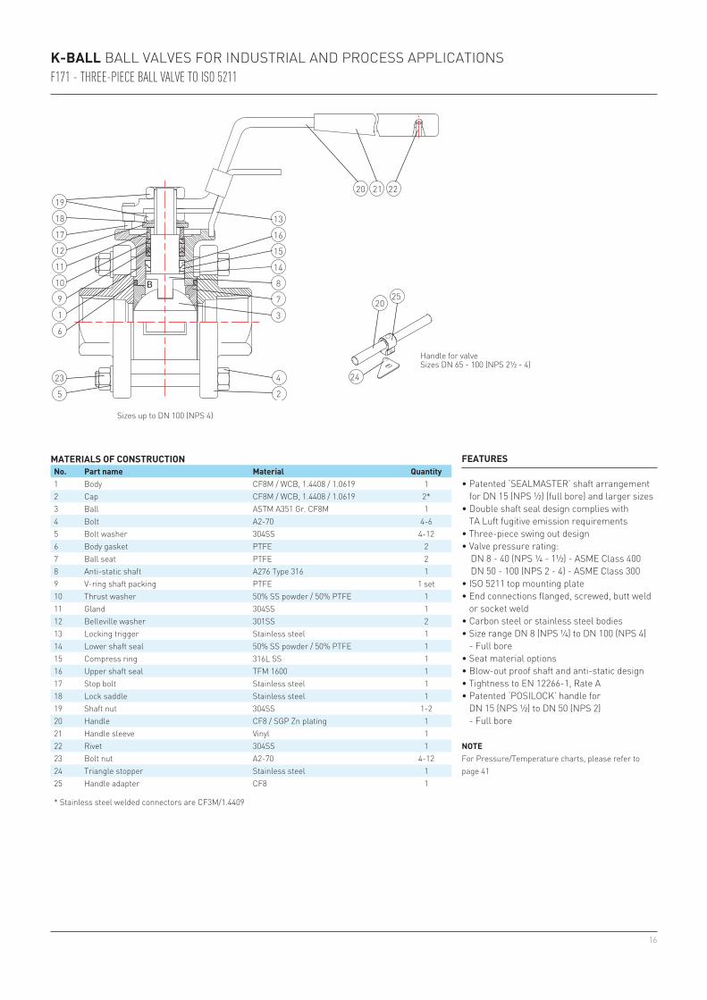
K-BALL BALL VALVES FOR INDUSTRIAL AND PROCESS APPLICATIONSF171 - THREE-PIECE BALL VALVE TO ISO 5211
FEATURES
• Patented ‘SEALMASTER’ shaft arrangement for DN 15 (NPS ½) (full bore) and larger sizes
• Double shaft seal design complies with TA Luft fugitive emission requirements
• Three-piece swing out design• Valve pressure rating: DN 8 - 40 (NPS ¼ - 1½) - ASME Class 400 DN 50 - 100 (NPS 2 - 4) - ASME Class 300• ISO 5211 top mounting plate• End connections flanged, screwed, butt weld
or socket weld• Carbon steel or stainless steel bodies• Size range DN 8 (NPS ¼) to DN 100 (NPS 4) - Full bore• Seat material options• Blow-out proof shaft and anti-static design• Tightness to EN 12266-1, Rate A• Patented ‘POSILOCK’ handle for
DN 15 (NPS ½) to DN 50 (NPS 2) - Full bore
NOTEFor Pressure/Temperature charts, please refer to page 41
MATERIALS OF CONSTRUCTIONNo. Part name Material Quantity1 Body CF8M / WCB, 1.4408 / 1.0619 12 Cap CF8M / WCB, 1.4408 / 1.0619 2*3 Ball ASTM A351 Gr. CF8M 14 Bolt A2-70 4-65 Bolt washer 304SS 4-126 Body gasket PTFE 27 Ball seat PTFE 28 Anti-static shaft A276 Type 316 19 V-ring shaft packing PTFE 1 set10 Thrust washer 50% SS powder / 50% PTFE 111 Gland 304SS 112 Belleville washer 301SS 213 Locking trigger Stainless steel 114 Lower shaft seal 50% SS powder / 50% PTFE 115 Compress ring 316L SS 116 Upper shaft seal TFM 1600 117 Stop bolt Stainless steel 118 Lock saddle Stainless steel 119 Shaft nut 304SS 1-220 Handle CF8 / SGP Zn plating 121 Handle sleeve Vinyl 122 Rivet 304SS 123 Bolt nut A2-70 4-1224 Triangle stopper Stainless steel 125 Handle adapter CF8 1
* Stainless steel welded connectors are CF3M/1.4409
• Double shaft sealing complies with TA Luft fugitive emission requirements
• Heavy duty, three piece ball valve• ISO 5211 top mounting plate• Fully enclosed bolting for sizes up to
DN 40 (NPS 1½) full bore and DN 50 (NPS 2) reduced bore
• End connections, screwed, butt weld and socket weld
• Seat material options• Size range DN 8 to 80 (NPS ¼ - 3) - Reduced bore to DN 100 (NPS 4)• Blow-out proof shaft and anti-static design• Tightness to EN 12266-1, Rate A• Optional casting per AD2000-WO• Patented ‘POSILOCK’ handle for DN 15 to 50
(NPS ½ - 2) - Full bore• Valve pressure rating: DN 8 - 50 (NPS ¼ - 2) - ASME Class 600 DN 65 - 80 (NPS 2½ - 3) - ASME Class 300
NOTEFor Pressure/Temperature charts, please refer to page 41
Sizes DN 8 - 40 (NPS ¼ - 1½)Drawing shows full bore construction
K-BALL BALL VALVES FOR INDUSTRIAL AND PROCESS APPLICATIONSF180F/R180F - THREE-PIECE BALL VALVE - FIRE SAFE (IMPERIAL)
ØN1: refer to thread options: NPT, BSPT, BSPP, DIN 2999
ØN1: refer to thread options: NPT, BSPT, BSPP, DIN 2999
FULL BORE DIMENSIONS (inch)NPS Ød A B G ØP ØF W H1 L1 L4 M ØN2 ØN3 t Wt (lbs)
REDUCED BORE DIMENSIONS (inch)NPS Ød A B G ØP F W H1 L1 L4 M ØN2 ØN3 t
Side viewFull bore:
NPS ⅜Reduced bore:
NPS ½
Side viewFull bore:
NPS ½ - 1½Reduced bore:
NPS ¾ - 2
Side viewFull bore:NPS 2 - 3
Reduced bore:NPS 2½ - 3
Threaded end Socket weld Butt weld
28
19
20
21
11
10
9
8
6
4
12 13 14
22
18 23 24
15 16
2 7 7a 3 5 1
17
K-BALL BALL VALVES FOR INDUSTRIAL AND PROCESS APPLICATIONSF190 - SPLIT BODY FLANGED BALL VALVE
FEATURES
• Patented ‘SEALMASTER’ shaft arrangement• Double shaft sealing complies with TA Luft
fugitive emission requirements• Blow-out proof shaft• ISO 5211 mounting plate• Anti-static design according to EN 1983 /
ISO 17292• Valve pressure rating: - ASME Class 150/300 - DIN PN 10/16/25/40 - JIS 10K/20K• Two piece, split body ball valve with flanged
ends• Carbon steel or stainless steel bodies• Locking device• Various seat material options• Investment cast body - DN 15 - 100 (NPS ½ - 4)• Sand cast body - DN 125 - 300 (NPS 5 - 12)• Size range DN 15 - 300 (NPS ½ - 12) - Full bore• Tightness to EN 12266-1, Rate A• Optional casting per AD2000-W0• Patented ‘POSILOCK’ handle for DN 15 - 50
(NPS ½ - 2) - Full bore
NOTEFor Pressure/Temperature charts, please refer to pages 42 and 43
MATERIALS OF CONSTRUCTIONNo. Part name Material Quantity1* Body ASTM A351 Gr. CF8M / ASTM A216 Gr. WCB 12* Cap ASTM A351 Gr. CF8M / ASTM A216 Gr. WCB 13 Ball ASTM A351 Gr. CF8M 14 Anti-static shaft A276 Type 316 (Note 1) 15 Ball seat PTFE 26 Body seal PTFE 17 Stud A193 Gr. B8 / A193 Gr. B7 4-267a Nut A194 Gr. 8 / A194 Gr. 2H 4-268 Lower shaft seal 50% SS powder / 50% PTFE 19 Compress ring 316L SS DN 15 - 100 (NPS ½ - 4) /
22 Locking trigger Stainless steel 123 Handle sleeve Vinyl 124 Rivet 304SS 1* For DIN valves, the body and cap material will be 1.4408/1.0619.* For JIS valves, the body and cap material will be SCS14A/SCPH2Note 1: Standard shaft material
Handle for valveSizes DN 65 - 300
(NPS 2½ - 12)
Body material Size Class 150, 10K, PN 10/16 Class 300, 20K, PN 25/40CF8M, SCS14A, 1.4408
K-BALL BALL VALVES FOR INDUSTRIAL AND PROCESS APPLICATIONSF190F - SPLIT BODY FLANGED BALL VALVE - FIRE SAFE
FEATURES
• Patented ‘SEALMASTER’ shaft arrangement• Double shaft seal design• Blow-out proof shaft• ISO 5211 mounting plate• Anti-static design according to EN 1983 /
ISO 17292 / BS5351• Valve pressure rating: - ASME Class 150/300 - DIN PN 10/16/25/40 - JIS 10K/20K• Two-piece, split-body ball valve• Flexible graphite body and shaft packing for
Hi-temp resistance• Secondary metal to metal seating surface• Fire tested: DN 15 - 200 (NPS ½ - 8): - API 607 5th edition - ISO 10497:2004 DN 50 - 300 (NPS 10-12): - API 607 4th edition• Size range DN 15 - 300 (NPS ½ - 12) - Full bore• Tightness to EN 12266-1, Rate A• Patented ‘POSILOCK’ handle for DN 15 - 50
(NPS ½ - 2) - Full bore
NOTEFor Pressure/Temperature charts, please refer to pages 42 and 43
MATERIALS OF CONSTRUCTIONNo. Part name Material Quantity1* Body ASTM A351 Gr. CF8M / ASTM A216 Gr. WCB 12* Cap ASTM A351 Gr. CF8M / ASTM A216 Gr. WCB 13 Ball ASTM A351 Gr. CF8M 14 Anti-static shaft A276 Type 316 (Note 1) 15 Ball seat PTFE 26 Body seal Graphite DN 15 - 100 (NPS ½ - 4) /
22 Locking trigger Stainless steel 123 Handle sleeve Vinyl 124 Rivet 304SS 1* For DIN valves, the body and cap material will be 1.4408/1.0619.* For JIS valves, the body and cap material will be SCS14A/SCPH2Note 1: Standard shaft material
Handle for valveSize DN 65 - 300
(NPS 2½ - 12)
Body material Size Class 150, 10K, PN 10/16 Class 300, 20K, PN 25/40CF8M, SCS14A, 1.4408
K-BALL BALL VALVES FOR INDUSTRIAL AND PROCESS APPLICATIONSCOMPLETE VALVE RANGE
NOTES1. Increase by 25% for MG1241, carbon and SS filled seat.2. Increase by 15% for dry gas or oil free products.3. Increase by 40% for dry gas (-100°C (-148°F) and below).4. Increase by 40% for gas or liquid with slurry powder (above -100°C (-148°F)).5. Increase by 40% for high viscosity fluid (above -100°C (-148°F)).6. For actuator sizing, we recommend to add at least 20% of the break-away torque of valve as safety factor.7. Valve torques refer to ball valves with full port. For reduced port valve torque take one size smaller.8. MAST (maximum allowable shaft torque) for full bore option. Other shaft options available.
PATENTED SEALMASTER® SHAFT SEAL ARRANGEMENT - AVAILABLE FOR FIGURES F130M, F133M, F171, F180/R180, F190
Our extremely high cycle shaft sealing design is accomplished by double sealing system. The high performance of our ball valves is mainly due to unique SEALMASTER® shaft seal arrangement, which provides a primary sealing. It has been specially designed and constructed to prevent line fluid permeation and resultant leakage. On top of this arrangement are multiple layers of V-ring shaft packing, this acts as secondary sealing. A set of Belleville washers automatically and constantly compresses the seals to adjust for wear, pressure and temperature fluctuations. Our ball valve is a stalwart barrier against fugitive emissions.
K-BALL BALL VALVES FOR INDUSTRIAL AND PROCESS APPLICATIONSSEALMASTER®
PARTS LISTNo. Parts name1 Handle2 Spring3 Locking trigger
POSILOCK HANDLE
Spring compressed
Pull the locking trigger up
Release the trigger. And the elasticity of the spring makes the trigger automatically bounce back to its original position
FEATURES
• Simple construction• Smooth action for locking trigger• Wrapped locking trigger design prevents the spring from coming out• The elasticity of the spring makes the trigger automatically bounce back to its original position,
which keeps the plate in position for firm locking. This also avoids unwanted valve operation caused by accident.
38
5
7
1
6
4
5
2
1
3
A
B
C
A
B
C
A
B
C
5
7
1
6
4
5
2
1
3
1 2 3
4 5 6
No. Part name Material Shaft seal arrangementPatented SEALMASTER shaft seal arrangement
MAIN FEATURES OF SEALMASTER® - PATENTED SHAFT SEAL ARRANGEMENT
• ‘Multiple’ sealing up to 6 areas (see view 1 - 6).• Encapsulated ‘static’ sealing achieved on upper thrust seal.• Constant sealing force transmitted to shaft (see arrow) and making the shaft primary sealing
‘positive’.• Excellent wear resistance on lower thrust seal (50% SS filled PTFE).• Standard shaft finish better than Ra 0.8 µm (150 Grit) to reduce seals friction to a minimum.
EXPLANATION OF SEALMASTER®
The live loaded SEALMASTER® is a combination of 3 components; (A) a cup and cone PFA/TFE upper thrust seal, (B) a cup and cone sintered SS316 center load ring and (C) a flat SS/TFE lower thrust seal. When tightened, the live loaded shaft pulls up and compressing the shaft thrust seals. As this happens, material from upper and lower thrust seal extrude between shaft and body enclosures. (See 1 - 6). The surfaces between the bottom of lower thrust seal and top of shaft flange are smooth and all rotation occurs between these two surfaces leaving the shaft thrust seal ‘static’ to create the best possible seal. As rotation continues, components bed in and keep seal performance constant with usage.
K-BALL BALL VALVES FOR INDUSTRIAL AND PROCESS APPLICATIONSSEALMASTER®
39
T R
200
400
600
800
1000
13.8
27.5
41.4
55.1
68.9
120082.7
-10(14)
50(122)
°C°F
150(302)
100(212)
250(482)
300(572)
200(392)
PN16 PN16
PN10 PN10
R
200
400
600
800
1000
1200
0(32)
-29(-20)
50(122)
°C°F
150(302)
100(212)
250(482)
300(572)
200(392)
13.8
27.5
41.4
55.1
68.9
82.7
R
200
400
600
800
1000
13.8
27.5
41.4
55.1
68.9
120082.7
-10(14)
50(122)
°C°F
150(302)
100(212)
250(482)
300(572)
200(392)
T
200
400
600
800
1000
13.8
27.5
41.4
55.1
68.9
120082.7
-10(14)
50(122)
°C°F
150(302)
100(212)
250(482)
300(572)
200(392)
T
Class 150
Class 150
K-BALL BALL VALVES FOR INDUSTRIAL AND PROCESS APPLICATIONSR110, F120, F130M - PRESSURE/TEMPERATURE CHARTS
= 1.0619 body rating
= 1.4408 body rating
= WCB body rating
= CF8M body rating
= PTFE
= RPTFE
R110ONE-PIECE BODY BALL VALVEDN 8 to DN 50 (NPS ¼ to NPS 2) - reduced bore
Pres
sure
in b
ar
Pres
sure
in p
si
Temperature
F120TWO-PIECE BODY BALL VALVEDN 8 to DN 50 (NPS ¼ to NPS 2) - full bore
Pres
sure
in b
ar
Pres
sure
in p
si
Temperature
F130MTHREE-WAY SPLIT-BODY BALL VALVEPN 16, PN 10:DN 50 to DN 150 (NPS 2 to NPS 6) - full boreDN 200 (NPS 8) - reduced bore
Pres
sure
in b
ar
Pres
sure
in p
si
Temperature
F130MTHREE-WAY SPLIT-BODY BALL VALVEASME Class 150:DN 50 to DN 150 (NPS 2 to NPS 6) - full boreDN 200 (NPS 8) - reduced bore
Pres
sure
in b
ar
Pres
sure
in p
si
Temperature
40
200
400
600
800
1000
13.8
27.5
41.4
55.1
68.9
120082.7
-10(14)
50(122)
°C°F
150(302)
100(212)
250(482)
300(572)
200(392)
PN63
PN25
PN40
PN10PN16
PN63
PN25
PN40
PN10PN16
RT
200
400
600
800
1000
1200
0(32)
-29(-20)
50(122)
°C°F
150(302)
100(212)
250(482)
300(572)
200(392)
13.8
27.5
41.4
55.1
68.9
82.7
RT
TR
200
400
600
800
1000
13.8
27.5
41.4
55.1
68.9
120082.7
-10(14)
50(122)
°C°F
150(302)
100(212)
250(482)
300(572)
200(392)
T
200
400
600
800
1000
13.8
27.5
41.4
55.1
68.9
120082.7
-10(14)
50(122)
°C°F
150(302)
100(212)
250(482)
300(572)
200(392)
R
K-BALL BALL VALVES FOR INDUSTRIAL AND PROCESS APPLICATIONSF133, R138, F155 - PRESSURE/TEMPERATURE CHARTS
DN 8 to DN 50 Rating: PN63
DN 65 to DN 100 Rating: PN40
= 1.0619 body rating
= 1.4408 body rating
= WCB body rating
= CF8M body rating
= PTFE
= RPTFE
F133M/F133MTTHREE- AND FOUR-WAY SPLIT-BODY BALL VALVEPN 63, PN 40, PN 25, PN 16, PN 10:DN 10 to DN 40 (NPS ⅜ to NPS 1½) - full boreDN 15 to DN 50 (NPS ½ to NPS 2) - reduced bore
Pres
sure
in b
ar
Pres
sure
in p
si
Temperature
F133M/F133MTTHREE- AND FOUR-WAY SPLIT-BODY BALL VALVEASME Class 150/300:DN 10 to DN 40 (NPS ⅜ to NPS 1½) - full boreDN 15 to DN 50 (NPS ½ to NPS 2) - reduced bore
Pres
sure
in b
ar
Pres
sure
in p
si
Temperature
R138THREE-WAY MULTI-PORT BALL VALVEDN 8 to DN 50 (NPS ¼ to NPS 2) - reduced bore
Pres
sure
in b
ar
Pres
sure
in p
si
Temperature
F155THREE-PIECE ECONOMICAL BALL VALVE
Pres
sure
in b
ar
Pres
sure
in p
si
Temperature
Class 300
Class 300
Class 150
Class 150
41
T R 4 S U K M H
200
400
600
800
1000
13.8
27.5
41.4
55.1
68.9
120082.7
-10(14)
50(122)
°C°F
150(302)
100(212)
250(482)
300(572)
200(392)
PN63
PN40PN40
PN63
T
4 S200
400
600
800
1000
13.8
27.5
41.4
55.1
68.9
120082.7
-10(14)
50(122)
°C°F
150(302)
100(212)
250(482)
300(572)
200(392)
PN63
PN40PN40
PN63
T
4 S
200
400
600
800
1000
13.8
27.5
41.4
55.1
68.9
120082.7
-10(14)
50(122)
°C°F
150(302)
100(212)
250(482)
300(572)
200(392)
PN16PN16
T4 S
200
600
800
1000
13.8
27.5
41.4
55.1
68.9
1200
1400
82.7
96.5
-10(14)
50(122)
°C°F
150(302)
100(212)
250(482)
300(572)
200(392)
PN100
PN40PN40
PN100
T
U
M
RH
4 S
KT R 4 S U K M H
200
400
600
800
1000
13.8
27.5
41.4
55.1
68.9
120082.7
-10(14)
50(122)
°C°F
150(302)
100(212)
250(482)
300(572)
200(392)
PN63
PN40PN40
PN63
T
4 S200
400
600
800
1000
13.8
27.5
41.4
55.1
68.9
120082.7
-10(14)
50(122)
°C°F
150(302)
100(212)
250(482)
300(572)
200(392)
PN63
PN40PN40
PN63
T
4 S
200
400
600
800
1000
13.8
27.5
41.4
55.1
68.9
120082.7
-10(14)
50(122)
°C°F
150(302)
100(212)
250(482)
300(572)
200(392)
PN16PN16
T4 S
200
600
800
1000
13.8
27.5
41.4
55.1
68.9
1200
1400
82.7
96.5
-10(14)
50(122)
°C°F
150(302)
100(212)
250(482)
300(572)
200(392)
PN100
PN40PN40
PN100
T
U
M
RH
4 S
K
T R 4 S U K M H
200
400
600
800
1000
13.8
27.5
41.4
55.1
68.9
120082.7
-10(14)
50(122)
°C°F
150(302)
100(212)
250(482)
300(572)
200(392)
PN63
PN40PN40
PN63
T
4 S200
400
600
800
1000
13.8
27.5
41.4
55.1
68.9
120082.7
-10(14)
50(122)
°C°F
150(302)
100(212)
250(482)
300(572)
200(392)
PN63
PN40PN40
PN63
T
4 S
200
400
600
800
1000
13.8
27.5
41.4
55.1
68.9
120082.7
-10(14)
50(122)
°C°F
150(302)
100(212)
250(482)
300(572)
200(392)
PN16PN16
T4 S
200
600
800
1000
13.8
27.5
41.4
55.1
68.9
1200
1400
82.7
96.5
-10(14)
50(122)
°C°F
150(302)
100(212)
250(482)
300(572)
200(392)
PN100
PN40PN40
PN100
T
U
M
RH
4 S
K
K-BALL BALL VALVES FOR INDUSTRIAL AND PROCESS APPLICATIONSF171/F171T, F180/R180/F180F/R180R - PRESSURE/TEMPERATURE CHARTS
NOTEFor PTFE seat, we recommend the maximum operating pressure not to exceed 68.9 bar (1000 psig) for DN 25 (NPS 1) and larger.
= PTFE
= RPTFE
= 25% carbon filled PTFE
= 50% SS filled PTFE
= UHMWP
= PEEK (ARLON 1330)
= MG1241
= TFM 1600
F171THREE-PIECE BALL VALVE TO ISO 5211PN 63, PN 40:DN 8 to DN 40 (NPS ¼ to NPS 1½) - full boreDN 50 to DN 100 (NPS 2 to NPS 4) - full bore
Pres
sure
in b
ar
Pres
sure
in p
si
Temperature
F171TTHREE-PIECE HIGH PURITY CLEAN BALL VALVEPN 63, PN 40:DN 15 to DN 40 (NPS ½ to NPS 1½) - full boreDN 50 to DN 100 (NPS 2 to NPS 4) - full bore
Pres
sure
in b
ar
Pres
sure
in p
si
Temperature
F171TTHREE-PIECE HIGH PURITY CLEAN BALL VALVEPN 16:DN 125 to DN 300 (NPS 5 to NPS 12) - full bore
Pres
sure
in b
ar
Pres
sure
in p
si
Temperature
F180/180R/F180F/R180RTHREE-PIECE HEAVY DUTY BALL VALVE / FIRE SAFEPN 100: DN 8 to DN 50 (NPS ¼ to NPS 2) - full bore DN 15 to DN 65 (NPS ½ to NPS 2½) - reduced borePN 40: DN 65 to DN 80 (NPS 2½ to NPS 3) - full bore DN 80 to DN 100 (NPS 3 to NPS 4) - reduced bore
= Body material 1.0619 Body Rating = Body material 1.4408 Body Rating = WCB Body Rating = CF8M Body Rating
200
400
600
800
1000
1200
0(32)
-29(-20)
50(122)
°C°F
150(302)
100(212)
250(482)
300(572)
200(392)
13.8
27.5
41.4
55.1
68.9
82.7
TH
U R
4 S
K
200
400
600
800
1000
1200
0(32)
-29(-20)
50(122)
°C°F
150(302)
100(212)
250(482)
300(572)
200(392)
13.8
27.5
41.4
55.1
68.9
82.7
T
H
UR
4 S
K
200
400
600
800
1000
1200
0(32)
-29(-20)
50(122)
°C°F
150(302)
100(212)
250(482)
300(572)
200(392)
13.8
27.5
41.4
55.1
68.9
82.7
T
H
U
R
4
S
K
200
400
600
800
1000
1200
0(32)
-29(-20)
50(122)
°C°F
150(302)
100(212)
250(482)
300(572)
200(392)
13.8
27.5
41.4
55.1
68.9
82.7
T R
H
4
S
T R 4 S U K H
Class 300
Class 300
Class 150
Class 150
Class 300
Class 300
Class 150
Class 150
K-BALL BALL VALVES FOR INDUSTRIAL AND PROCESS APPLICATIONSF190/F190F - PRESSURE/TEMPERATURE CHARTS
Note 1
= 1.0619 body rating
= 1.4408 body rating
= WCB body rating
= CF8M body rating
F190/F190F - ASMESPLIT-BODY FLANGED BALL VALVEDN 15 to DN 20 (NPS ½ to NPS ¾) - full bore
Pres
sure
in b
ar
Pres
sure
in p
si
Temperature
F190/F190F - ASMESPLIT-BODY FLANGED BALL VALVEDN 25 to DN 65 (NPS 1 to NPS 2½) - full bore
Pres
sure
in b
ar
Pres
sure
in p
si
Temperature
F190/F190F - ASMESPLIT-BODY FLANGED BALL VALVEDN 80 to DN 100 (NPS 3 to NPS 4) - full bore
Pres
sure
in b
ar
Pres
sure
in p
si
Temperature
F190/F190F - ASMESPLIT-BODY FLANGED BALL VALVEDN 125 to DN 300 (NPS 5 to NPS 12) - full bore
Pres
sure
in b
ar
Pres
sure
in p
si
Temperature
Class 300
Class 300
Class 150
Class 150
Class 300
Class 300
Class 150
Class 150
NOTES1. DN 200 and 250 (NPS 8 and 10) maximum operation pressure 27.6 bar (400 psig).
Please consult factory for this range of application.2. DN 125 and 150 (NPS 5 and 6) maximum operation pressure 34.5 bar (500 psig).3. DN 300 (NPS 12) maximum operation pressure 20.7 bar (300 psig).
50% SS filled PTFE and 25% carbon filled PTFE shall not exceed this rating line for ASME Class 300.
Note 2
Note 3
= PTFE
= RPTFE
= 25% carbon filled PTFE
= 50% SS filled PTFE
= UHMWP
= PEEK (ARLON 1330)
= TFM 1600
43
T R 4 S U K H
200
400
600
800
1000
13.8
27.5
41.4
55.1
68.9
120082.7
-10(14)
50(122)
°C°F
150(302)
100(212)
250(482)
300(572)
200(392)
PN25
PN10PN16
PN25
PN10
PN16
T HU
R
4
S
K
200
400
600
800
1000
13.8
27.5
41.4
55.1
68.9
120082.7
-10(14)
50(122)
°C°F
150(302)
100(212)
250(482)
300(572)
200(392)
PN25
PN10PN16
PN25
PN10
PN16
T HU
R
4
S
K
200
400
600
800
1000
13.8
27.5
41.4
55.1
68.9
120082.7
-10(14)
50(122)
°C°F
150(302)
100(212)
250(482)
300(572)
200(392)
PN25
PN10PN16
PN25
PN10
PN16
T
U H
R
4
SK
PN40PN40
PN40PN40
PN40PN40
200
400
600
800
1000
13.8
27.5
41.4
55.1
68.9
120082.7
-10(14)
50(122)
°C°F
150(302)
100(212)
250(482)
300(572)
200(392)
T
H
R4
SPN25
PN10PN16
PN25
PN40
PN10PN16
PN40
K-BALL BALL VALVES FOR INDUSTRIAL AND PROCESS APPLICATIONSF190/F190F - PRESSURE/TEMPERATURE CHARTS
Note 1
= 1.0619 body rating
= 1.4408 body rating
= WCB body rating
= CF8M body rating
F190/F190F - DINSPLIT-BODY FLANGED BALL VALVEDN 15 to DN 20 (NPS ½ to NPS ¾) - full bore
Pres
sure
in b
ar
Pres
sure
in p
si
Temperature
F190/F190F - DINSPLIT-BODY FLANGED BALL VALVEDN 25 to DN 65 (NPS 1 to NPS 2½) - full bore
Pres
sure
in b
ar
Pres
sure
in p
si
Temperature
F190/F190F - DINSPLIT-BODY FLANGED BALL VALVEDN 80 to DN 100 (NPS 3 to NPS 4) - full bore
Pres
sure
in b
ar
Pres
sure
in p
si
Temperature
F190/F190F - DINSPLIT-BODY FLANGED BALL VALVEDN 125 to DN 300 (NPS 5 to NPS 12) - full bore
Pres
sure
in b
ar
Pres
sure
in p
si
Temperature
NOTES1. DN 200 and 250 (NPS 8 and 10) maximum operation pressure 27.6 bar (400 psig).
Please consult factory for this range of application.2. DN 125 and 150 (NPS 5 and 6) maximum operation pressure 34.5 bar (500 psig).3. DN 300 (NPS 12) maximum operation pressure 20.7 bar (300 psig).
Note 2
Note 3
= PTFE
= RPTFE
= 25% carbon filled PTFE
= 50% SS filled PTFE
= UHMWP
= PEEK (ARLON 1330)
= TFM 1600
44
Neither Emerson, Emerson Automation Solutions, nor any of their affiliated entities assumes responsibility for the selection, use or maintenance of any product. Responsibility for proper selection, use, and maintenance of any product remains solely with the purchaser and end user.
K-Ball is a mark owned by one of the companies in the Emerson Automation Solutions business unit of Emerson Electric Co. Emerson Automation Solutions, Emerson and the Emerson logo are trademarks and service marks of Emerson Electric Co. All other marks are the property of their respective owners.
The contents of this publication are presented for informational purposes only, and while every effort has been made to ensure their accuracy, they are not to be construed as warranties or guarantees, express or implied, regarding the products or services described herein or their use or applicability. All sales are governed by our terms and conditions, which are available upon request. We reserve the right to modify or improve the designs or specifications of such products at any time without notice.