Page 1
ABSTRACT
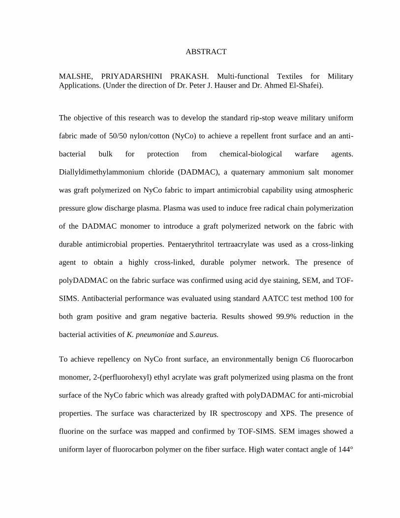
MALSHE, PRIYADARSHINI PRAKASH. Multi-functional Textiles for Military
Applications. (Under the direction of Dr. Peter J. Hauser and Dr. Ahmed El-Shafei).
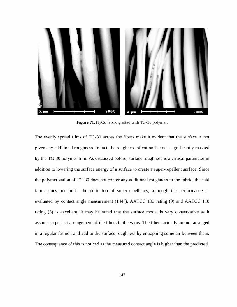
The objective of this research was to develop the standard rip-stop weave military uniform
fabric made of 50/50 nylon/cotton (NyCo) to achieve a repellent front surface and an anti-
bacterial bulk for protection from chemical-biological warfare agents.
Diallyldimethylammonium chloride (DADMAC), a quaternary ammonium salt monomer
was graft polymerized on NyCo fabric to impart antimicrobial capability using atmospheric
pressure glow discharge plasma. Plasma was used to induce free radical chain polymerization
of the DADMAC monomer to introduce a graft polymerized network on the fabric with
durable antimicrobial properties. Pentaerythritol tertraacrylate was used as a cross-linking
agent to obtain a highly cross-linked, durable polymer network. The presence of
polyDADMAC on the fabric surface was confirmed using acid dye staining, SEM, and TOF-
SIMS. Antibacterial performance was evaluated using standard AATCC test method 100 for
both gram positive and gram negative bacteria. Results showed 99.9% reduction in the
bacterial activities of K. pneumoniae and S.aureus.
To achieve repellency on NyCo front surface, an environmentally benign C6 fluorocarbon
monomer, 2-(perfluorohexyl) ethyl acrylate was graft polymerized using plasma on the front
surface of the NyCo fabric which was already grafted with polyDADMAC for anti-microbial
properties. The surface was characterized by IR spectroscopy and XPS. The presence of
fluorine on the surface was mapped and confirmed by TOF-SIMS. SEM images showed a
uniform layer of fluorocarbon polymer on the fiber surface. High water contact angle of 144°
Page 2
was obtained on the surface. The surface also achieved a high AATCC Test Method 193
rating of 9 and AATCC Test Method 118 rating of 5, indicating that the surface could repel a
fluid with surface tension as low as 24 dynes/cm.
Appropriate experimental designs and statistical modeling of data helped identify the
experimental space and optimal factor combinations for best response. The study helped
create a multi-functional fabric with an anti-bacterial bulk, hydrophilic back surface and
repellent front surface for enhanced protective and aesthetic values.
Page 3
© Copyright 2011 by Priyadarshini Malshe
All Rights Reserved
Page 4
Multi-functional Textiles for Military Applications
by
Priyadarshini Malshe
A dissertation submitted to the Graduate Faculty of
North Carolina State University
in partial fulfillment of the
requirements for the Degree of
Doctor of Philosophy
Fiber and Polymer Science
Raleigh, North Carolina
2012
APPROVED BY:
______________________________ ______________________________
Mohamed Bourham Donald Thompson
_____________________________ ______________________________
Peter Hauser Ahmed El-Shafei
Chair of Advisory Committee Co-chair of Advisory Committee
Page 5
ii
BIOGRAPHY
Priyadarshini Malshe was born on October 31, 1984 in India to Leena and Prakash Malshe.
She earned her Bachelor‟s degree in fiber and textile processing technology from Institute of
Chemical Technology, Mumbai, India in May, 2006.
She went on to work with BASF India Ltd. in July 2006 in their product development
division for performance chemicals for textiles for a year.
She received her Master of Science degree in Textile Chemistry in 2009 from the North
Carolina State University, College of Textiles.
Page 6
iii
ACKNOWLEDGMENTS
First of all, I wish to express my heartfelt appreciation for my advisors, Dr. Peter Hauser and
Dr. Ahmed El-Shafei. They have been the most wonderful teachers, advisors, and scientists
whose support, encouragement and help made my time at NC State University extremely
fruitful. I also thank my committee members Dr. Mohamed Bourham and Dr. Don Thompson
for their valuable suggestions, time, and support.
I extend special thanks to Dr. Jon Rust and Dr. William Oxenham, who believed in me and
encouraged me at each step that I took towards successful completion.
I express my sincere gratitude to Dean Blan Godfrey and Dr. Tim Clapp for giving me the
most wonderful opportunities to study, learn and practice the exciting concepts of Six Sigma
which greatly helped me shape my doctoral project.
I sincerely appreciate the staff members at College of Textiles, especially Traci Figura, Vicki
Stocksdale, Kate Ryan, Dzeung Nguyen, Jeff Krauss and Birgit Andersen who were always
very helpful with all the paper-work and lab support.
Lots of hugs to my friends Dnyanada Satam, Akshaya Patrachari, Richa Maheshwari, Ravi
Vangala and Dr. Vamsi Jasti, who made me feel at home away from home. Special thanks to
my wonderful friends at school-Maryam Mazloumpour, Dr. Rani, Melek Gul, Aylin Karahan
and Eli Amirnasr for their support, appreciation and the fun times. I also thank my friends
Aditi Shukla, Dr. Kaushal Mishra, Dr. Johannes Dahl and Dr. Jason Osborne for all the
caring and entertainment they provided.
Page 7
iv
And last but not the least; I thank my parents Dr. Prakash Malshe (who is the only Medical
doctor in this acknowledgment) and Mrs. Leena Malshe, my elder brother Dr. Rohit Malshe
and my uncle Dr. Vinod Malshe for their encouragement and patience.
Go Wolfpack!
Page 8
v
TABLE OF CONTENTS
LIST OF FIGURES…………………………………………………………………………viii
LIST OF TABLES…………………………………………………………………………...xii
CHAPTER 1. INTRODUCTION ............................................................................................. 1
CHAPTER 2. CHEMICAL BIOLOGICAL WARFARE AGENTS: A BRIEF HISTORY
AND THREATS IN THE CURRENT SCENARIO ................................................................ 5
2.1. Chemical-Biological warfare agents: A brief history .................................................... 5
2.2. Chemical-Biological warfare agents .............................................................................. 7
2.2.1. Nerve agents ................................................................................................................ 9
2.2.2. Vesicant/Blister agents .............................................................................................. 11
2.2.3. Blood agents .............................................................................................................. 13
2.2.4. Pulmonary/Choking agents ....................................................................................... 14
2.3. CBWAs protective military uniforms .......................................................................... 20
CHAPTER 3. MULTIFUNCTIONAL MILITARY TEXTILE: SUPER-REPELLENCY
AND SELF-DETOXIFICATION ........................................................................................... 23
3.1. Super-repellency: Surface tension approach ................................................................ 23
3.1.1. Contact angle on a smooth surface ............................................................................ 23
3.1.2. Rough surface models ............................................................................................... 24
2.2. Contact angle hysteresis ............................................................................................... 30
3.3. Modeling of Rough Super-repellent Surfaces .............................................................. 35
3.4. Self-detoxification for protection from CBWAs .......................................................... 45
CHAPTER 4. THE PLASMA APPROACH .......................................................................... 55
4.1. Plasma .......................................................................................................................... 55
4.2. Plasma parameters ........................................................................................................ 59
4.2.1. Density of plasma species ......................................................................................... 59
4.2.2. Plasma temperature ................................................................................................... 61
4.2.3. Debye length ............................................................................................................. 63
4.2.4. Plasma frequency ...................................................................................................... 64
4.3. Atmospheric pressure plasma ....................................................................................... 65
4.3.1. Corona discharges ..................................................................................................... 66
Page 9
vi
4.3.2. Dielectric barrier discharge (DBD) ........................................................................... 66
4.3.3. Atmospheric pressure plasma jet (APPJ) .................................................................. 67
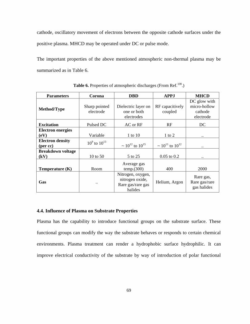
4.3.4. Microhollow cathode discharge (MHCD) ................................................................. 68
4.4. Influence of Plasma on Substrate Properties ................................................................ 69
4.4.1. Cross-linking ............................................................................................................. 70
4.4.2. Etching and Re-deposition ........................................................................................ 71
4.4.3. Deposition ................................................................................................................. 71
4.4.4. Chain Scission and Functionalization ....................................................................... 71
4.5. Plasma polymerization ................................................................................................. 73
4.6. Super-repellent chemistry and plasma ......................................................................... 74
CHAPTER 5. BASIC STATISTICS AND DESIGN OF EXPERIMENTS FOR SCIENTIFIC
RESEARCH ............................................................................................................................ 77
5.1. Introduction ...................................................................................................................... 77
5.2. Design of Experiments ..................................................................................................... 81
5.3. Most Commonly Used Designs ....................................................................................... 81
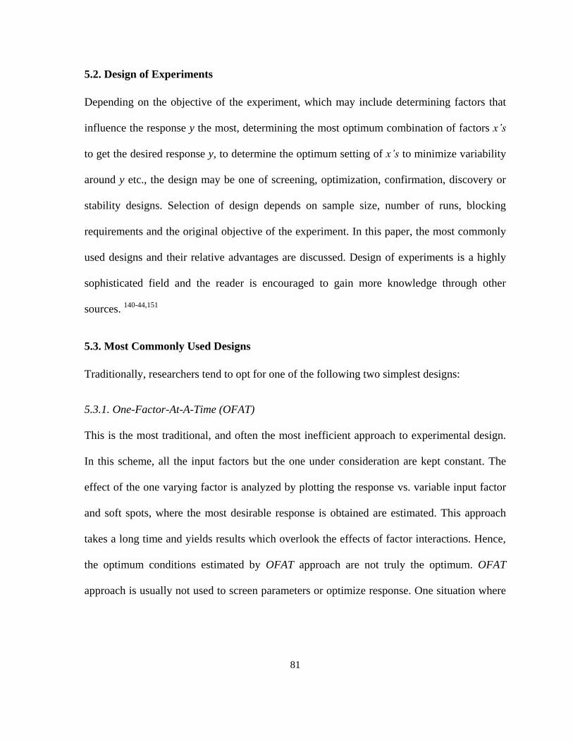
5.3.1. One-Factor-At-A-Time (OFAT) ................................................................................ 81
5.3.2. Full Factorial Designs .............................................................................................. 82
5.4 Screening Designs ............................................................................................................. 83
5.4.1. Two-Level Factorial Designs .................................................................................... 83
5.4.2. Two-level Fractional Factorial Designs ................................................................... 84
5.5. Response Surface Methods .............................................................................................. 85
5.5.1. Central Composite Design ........................................................................................ 86
5.5.2. Box-Behnken Design ................................................................................................. 87
5.6. Methods for Statistical Analysis of Experimental Data ................................................... 88
5.6.1. Error Estimates ......................................................................................................... 89
5.6.2. T-Test and ANOVA .................................................................................................... 89
CHAPTER 6. EXPERIMENTAL ........................................................................................... 91
6.1. Materials ....................................................................................................................... 91
6.2. Apparatus ..................................................................................................................... 92
6.3. AATCC Test Method 100-2004: Assessment of Antibacterial Finishes on Textile
Materials .............................................................................................................................. 97
Page 10
vii
6.5. AATCC Test Method 118-2007: Oil Repellency: Hydrocarbon Resistance Test ...... 98
6.6. Experimental Procedure ............................................................................................. 100
6.6.1. Experiment-1: Graft polymerization of DADMAC on 50-50% Nylon Cotton fabric
surface by wet process ....................................................................................................... 100
6.6.2. Experiment-2: Graft polymerization of DADMAC on 50-50% Nylon Cotton fabric
surface by downstream helium plasma treatment ............................................................. 104
6.6.3. Experiment-3: Graft polymerization of 2-(perfluorohexyl)ethyl acrylate (TG-30) on
front surface of 50-50% Nylon Cotton fabric ................................................................... 108
CHAPTER 7. RESULTS AND DISCUSSION .................................................................... 113
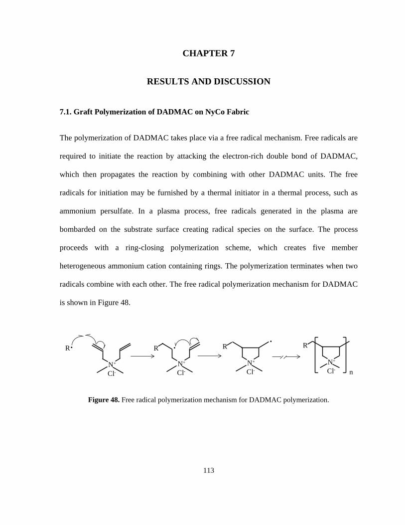
7.1. Graft Polymerization of DADMAC on NyCo Fabric ................................................ 113
7.2.1. Acid dyeing with Sirius Red F3B ........................................................................... 115
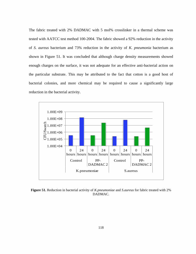
7.2.2. AATCC Test Method 100-2004: Assessment of Antibacterial Finishes on Textile
Materials ............................................................................................................................ 117
7.2.3. Attenuated Total Reflectance-Fourier Transform Infra Red (ATR-FTIR)
Spectroscopy ..................................................................................................................... 121
7.2.4. X-Ray Photoelectron Spectroscopy (XPS) ............................................................. 123
7.2.5. Time of Flight-Secondary Ion Mass Spectroscopy (TOF-SIMS) ........................... 127
7.2.6. Scanning Electron Microscopy (SEM) ................................................................... 133
7.3. Graft Polymerization of 2-(perfluorohexyl)ethyl acrylate on NyCo Fabric .............. 135
7.4.1. AATCC Test Method 193-2007 .............................................................................. 139
7.4.2. AATCC Test Method 118-2007 .............................................................................. 139
7.4.2. Scanning Electron Microscopy (SEM) ................................................................... 146
7.4.3. Infra Red (IR) Spectroscopy ................................................................................... 148
7.4.4. X-Ray Photoelectron Spectroscopy (XPS) ............................................................. 150
7.4.5. Time of Flight-Secondary Ion Mass Spectroscopy (TOF-SIMS) ........................... 154
CHAPTER 8. CONCLUSIONS ........................................................................................... 159
REFERENCES…………………………………………………………………………...…..163
APPENDIX…………………………………………………………………………………172
Page 11
viii
LIST OF FIGURES
Figure 1. Chemical Structure of Sarin ...................................................................................... 9
Figure 2. Chemical structure of Cyclosarin .............................................................................. 9
Figure 3. Chemical structure of VX ........................................................................................ 10
Figure 4. Chemical structutre of Soman ................................................................................. 10
Figure 5. Chemical structure of Tabun ................................................................................... 11
Figure 6. Chemical structure of Lewisite ................................................................................ 12
Figure 7. Chemical structure of Sulfur Mustard ..................................................................... 12
Figure 8. Chemical weapon detonation .................................................................................. 18
Figure 9. Effect of primary cloud with respect to wind velocity ............................................ 19
Figure 10. Approximate lifetimes of CWA contamination. ................................................... 20
Figure 11. JSLIST with a chemical protection mask .............................................................. 21
Figure 12. P2i Ltd's 2000L plasma chamber .......................................................................... 22
Figure 13. (a) Young's model for smooth surfaces, (b) Wenzel's model for rough surface and
intimate contact between liquid and solids (c) Cassie-Baxter's model for porous materials and
(d) Marmur's modification for Cassie-Baxter model. ............................................................. 26
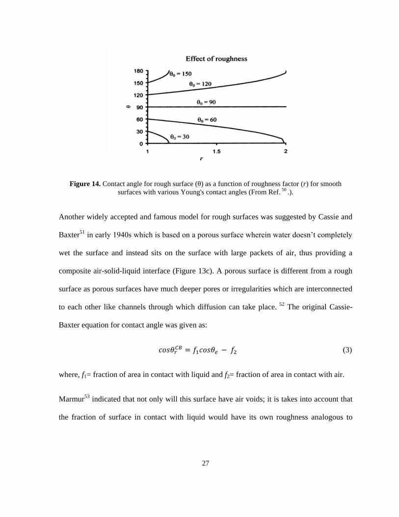
Figure 14. Contact angle for rough surface (θ) as a function of roughness factor (r) for
smooth surfaces with various Young's contact angles ............................................................ 27
Figure 15. Free-energy barrier separating the meta-stable Cassie-Baxter state from Wenzel
state. ........................................................................................................................................ 29
Figure 16. Transition between Cassie-Baxter and Wenzel models. ....................................... 30
Figure 17. (a) Contact angle hysteresis and self-cleaning on a super-repellent surface and (b)
droplet on a tilted plane. .......................................................................................................... 32
Figure 18. (A) and (B) Re-entrant surface curvature effect, (C) and (D) Micro-hoodoo
structures with square and circular tops. ................................................................................. 38
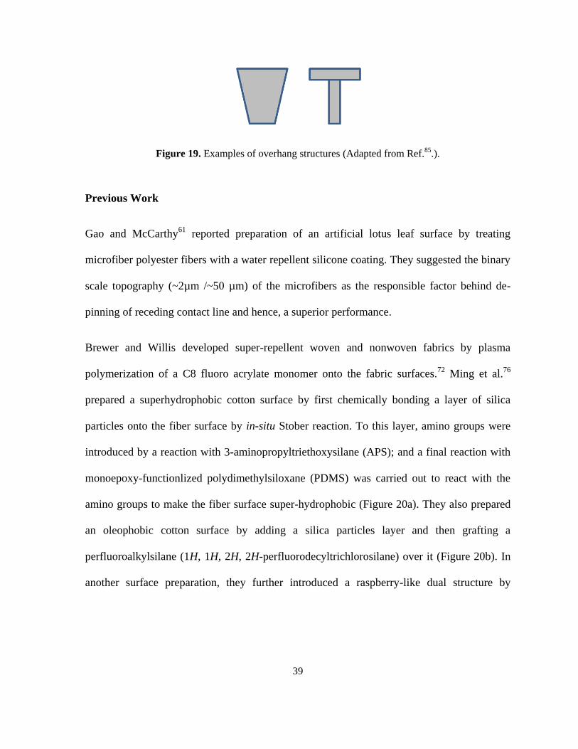
Figure 19. Examples of overhang structures. .......................................................................... 39
Figure 20. (a) Chemical bonding of silica particles to cotton, followed by introduction of
amino groups and reaction with PDMS (b) grafting of perfluoroalkyl silane onto silica
particles (c) introduction of silica nanoparticles followed by perfluoroalkyl silane grafting. 41
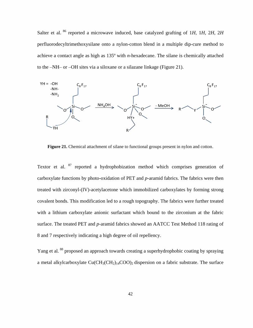
Figure 21. Chemical attachment of silane to functional groups present in nylon and cotton. 42
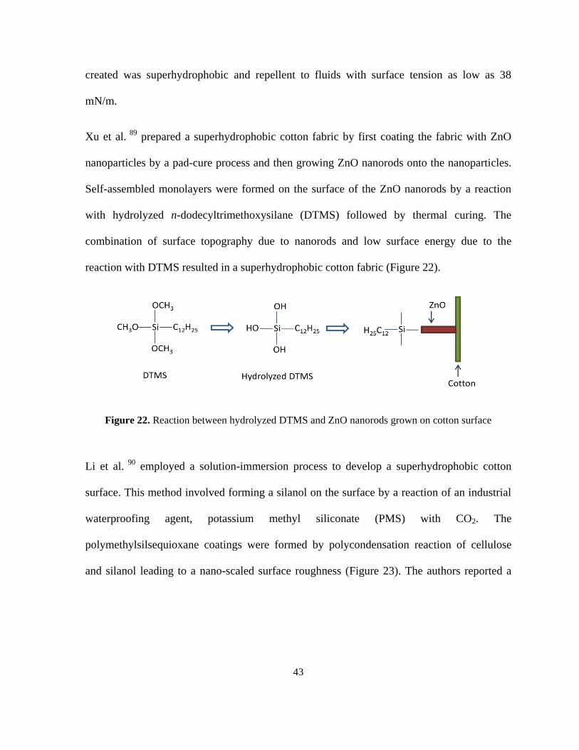
Figure 22. Reaction between hydrolyzed DTMS and ZnO nanorods grown on cotton surface
................................................................................................................................................. 43
Figure 23. Reaction between potassium methyl siliconate and CO2 followed by
polycondensation on cotton surface. ....................................................................................... 44
Figure 24. Chemical structures of (a) 3-allyl-5,5-dimethylhydantoin, (b) 1-chloro-5,5-
dimethyl-3-(triethoxysilylpropyl)hydantoin. .......................................................................... 50
Page 12
ix
Figure 25. Chemical structure of diallyldimethylammonium chloride (DADMAC). ............ 52
Figure 26. Constituents of plasma. ......................................................................................... 55
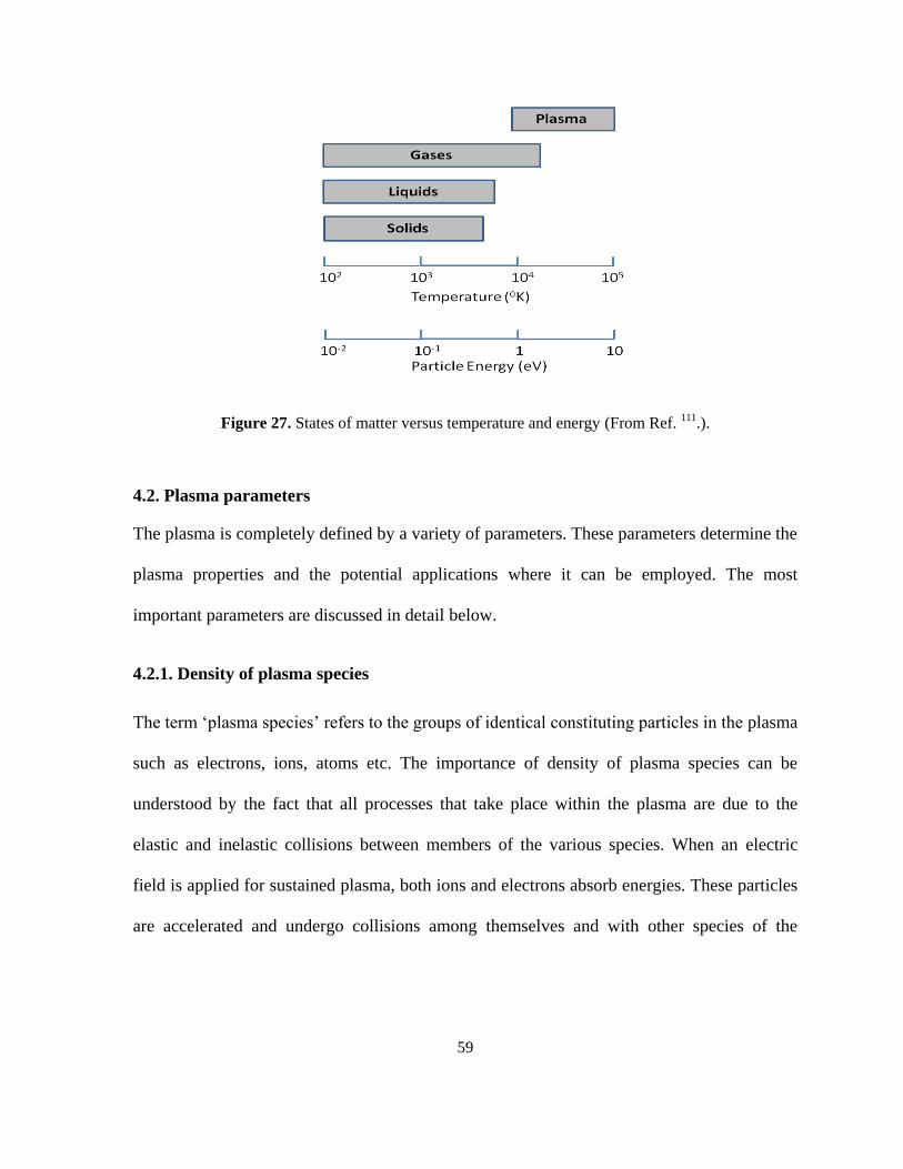
Figure 27. States of matter versus temperature and energy. ................................................... 59
Figure 28. Electron and gas temperature as a function of pressure ........................................ 63
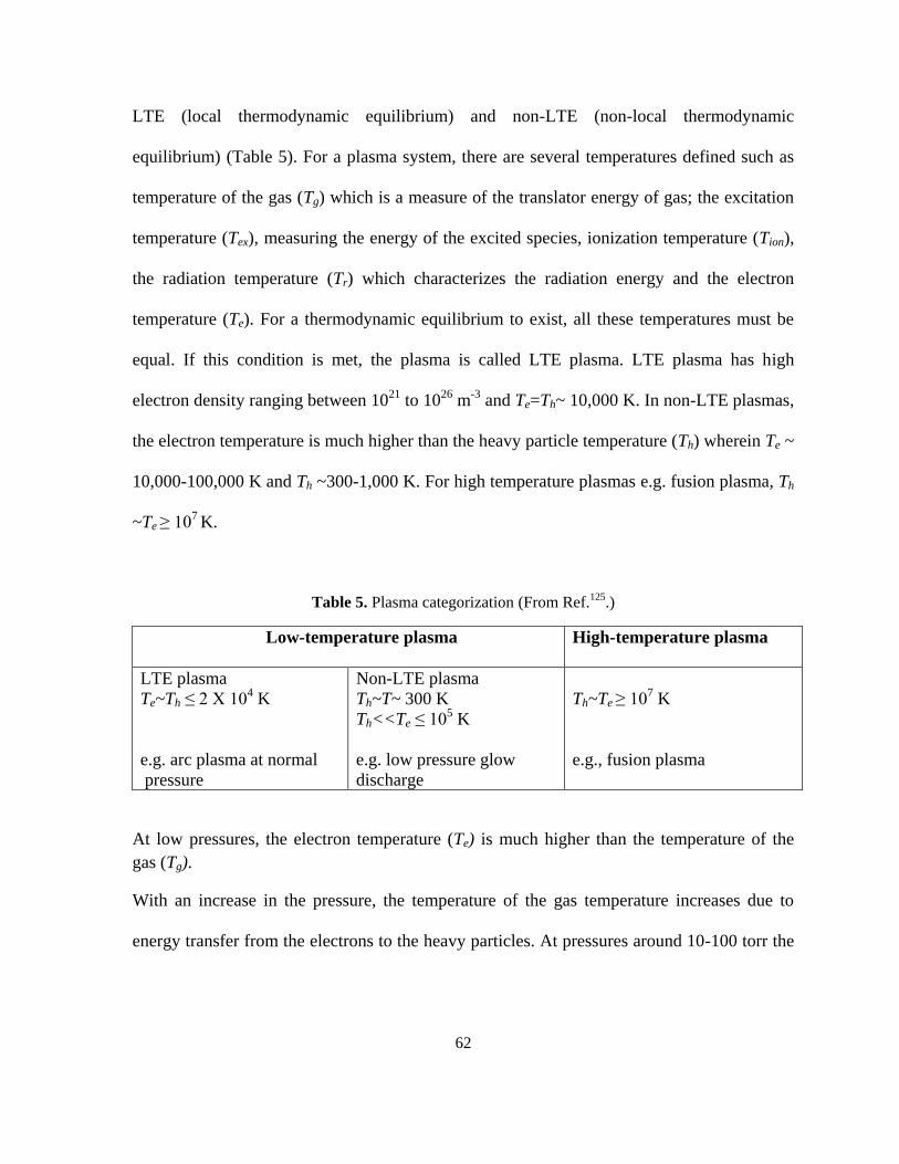
Figure 29. Schematics of corona discharge. ........................................................................... 66
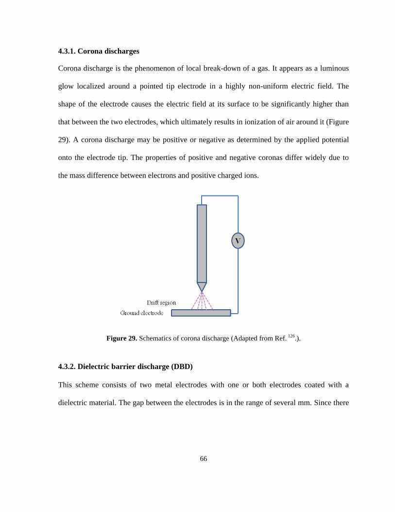
Figure 30. Schematics of DBD; 1. Electrodes, 2. Dielectric layer ......................................... 67
Figure 31. APPR 300-13 device from ApJeT, Inc. ................................................................. 68
Figure 32. Plasma processes ................................................................................................... 72
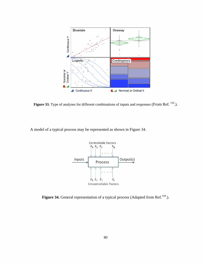
Figure 33. Type of analyses for different combinations of inputs and responses ................... 80
Figure 34. General representation of a typical process. .......................................................... 80
Figure 35. Two level factorial design with two factors and center points. ............................. 84
Figure 36. An example of a response surface generated in JMP®. ........................................ 86
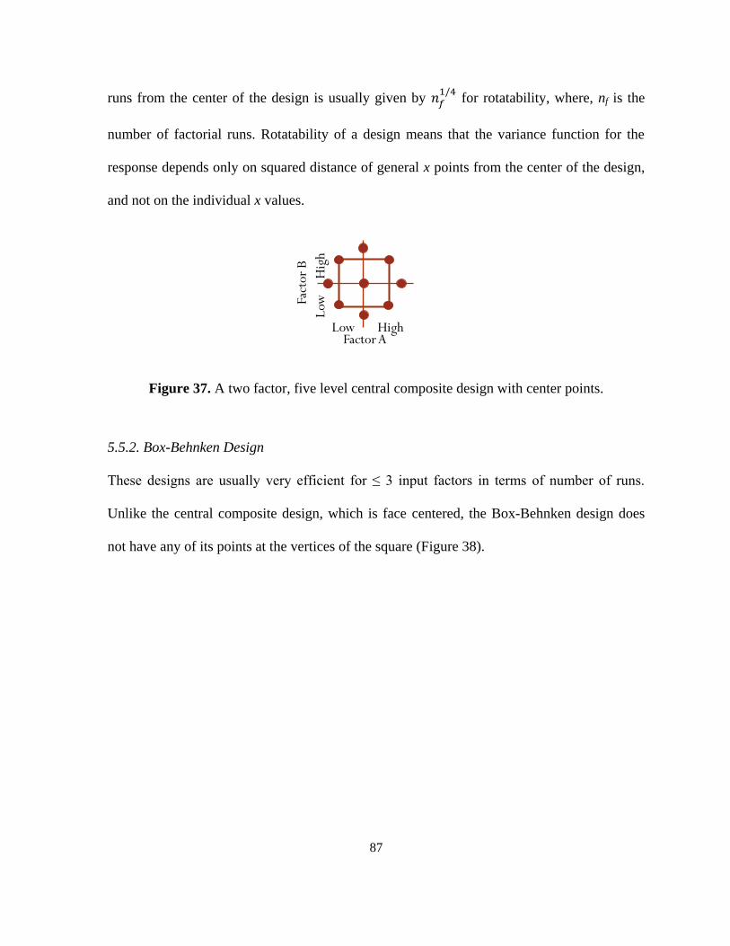
Figure 37. A two factor, five level central composite design with center points. .................. 87
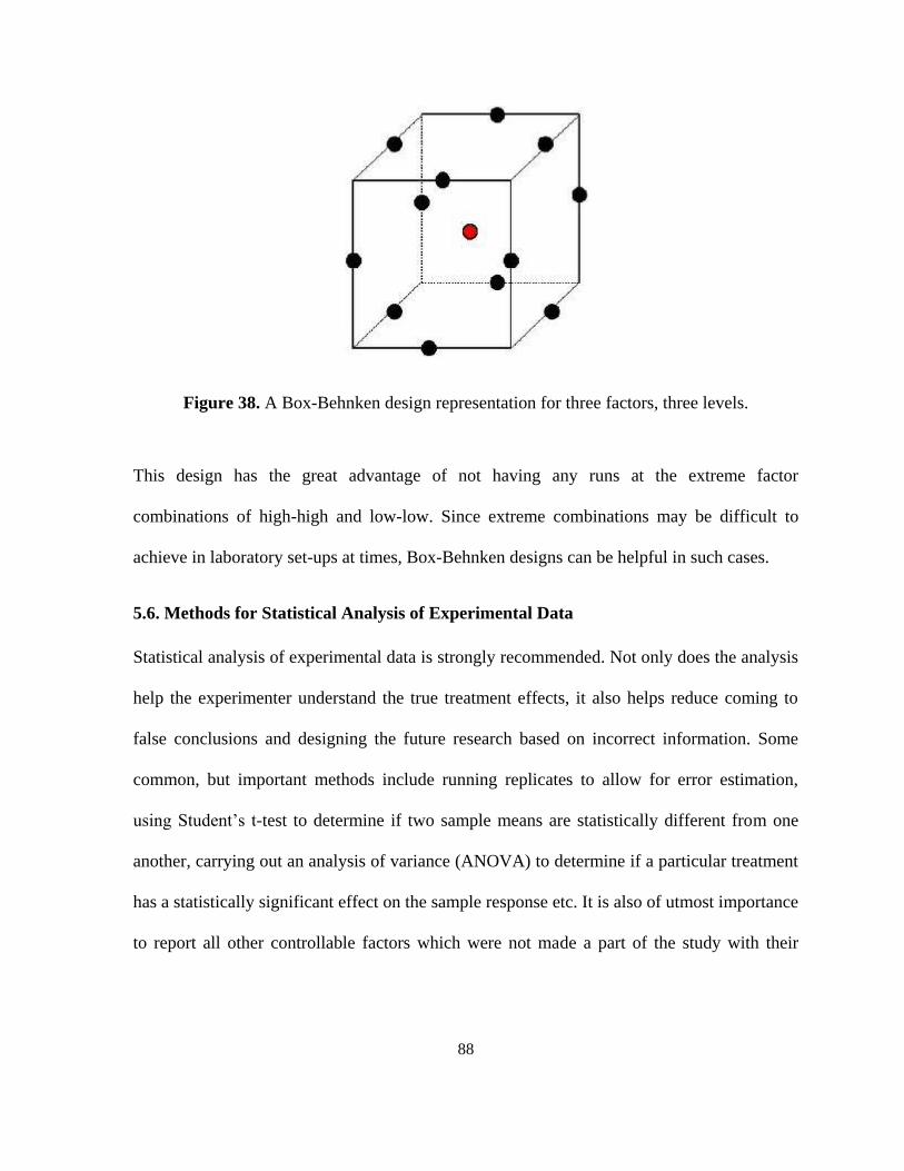
Figure 38. A Box-Behnken design representation for three factors, three levels. .................. 88
Figure 39. Chemical structures of (a) pentaerythritol tetraacrylate and (b) diethylene glycol
diacrylate. ................................................................................................................................ 92
Figure 40. The APPR reactor schematics. .............................................................................. 93
Figure 41. APPR device electrode schematic in downstream more and in-situ mode ........... 95
Figure 42. Process map for thermal graft polymerzation of DADMAC on NyCo fabric. ... 100
Figure 43. Factor profiler for thermal graft polymerization of DADMAC on NyCo. .......... 103
Figure 44. Process flow for plasma induced graft polymerization of DADMAC on NyCo. 104
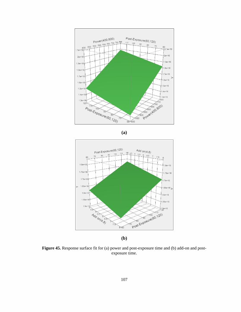
Figure 45. Response surface fit for (a) power and post-exposure time and (b) add-on and
post-exposure time. ............................................................................................................... 107
Figure 46. Process schematic of plasma induced graft polymerization of TG-30 on NyCo
fabric. .................................................................................................................................... 108
Figure 47. Response surface showing AATCC 193 rating as the response for (a) plasma
power and exposure time and (b) plasma power and monomer flow rate. ........................... 111
Figure 48. Free radical polymerization mechanism for DADMAC polymerization. ........... 113
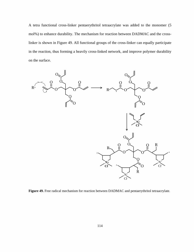
Figure 49. Free radical mechanism for reaction between DADMAC and pentaerythritol
tetraacrylate. .......................................................................................................................... 114
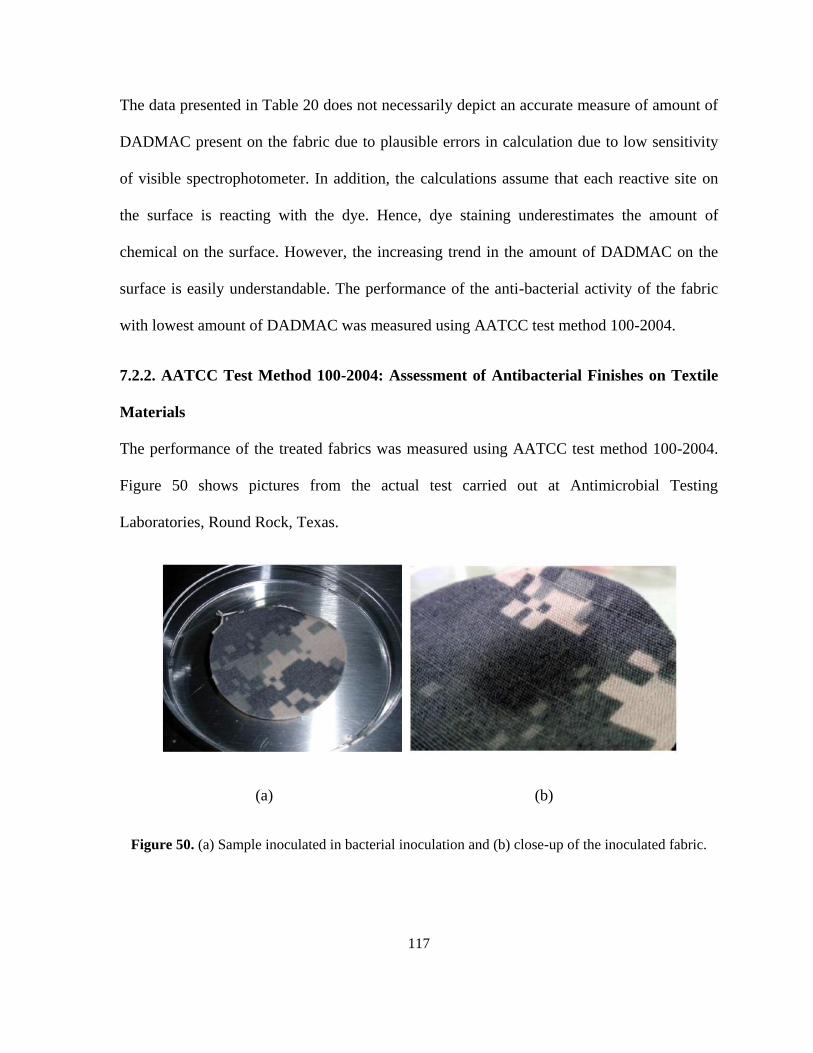
Figure 50. (a) Sample inoculated in bacterial inoculation and (b) close-up of the inoculated
fabric. .................................................................................................................................... 117
Figure 51. Reduction in bacterial activity of K.pneumoniae and S.aureus for fabric treated
with 2% DADMAC. ............................................................................................................. 118
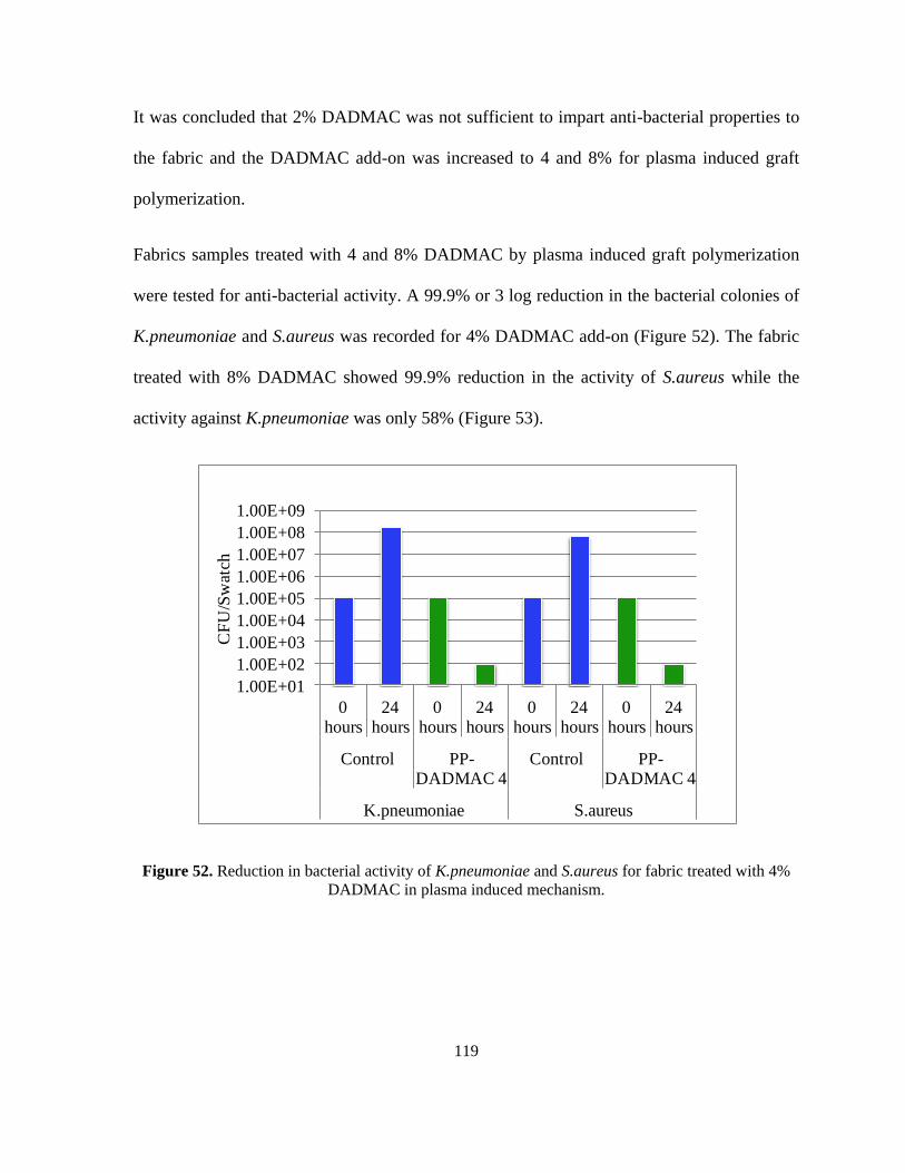
Figure 52. Reduction in bacterial activity of K.pneumoniae and S.aureus for fabric treated
with 4% DADMAC in plasma induced mechanism. ............................................................ 119
Figure 53. Reduction in bacterial activity of K.pneumoniae and S.aureus for fabric treated
with 8% DADMAC in plasma induced mechanism. ............................................................ 120
Page 13
x
Figure 54. ATR-FTIR spectra for control NyCo and polyDADMAC grafted NyCo fabric. 122
Figure 55. XPS speactra for (a) control NyCo and (b) polyDADMAC grafted NyCo fabric.
............................................................................................................................................... 124
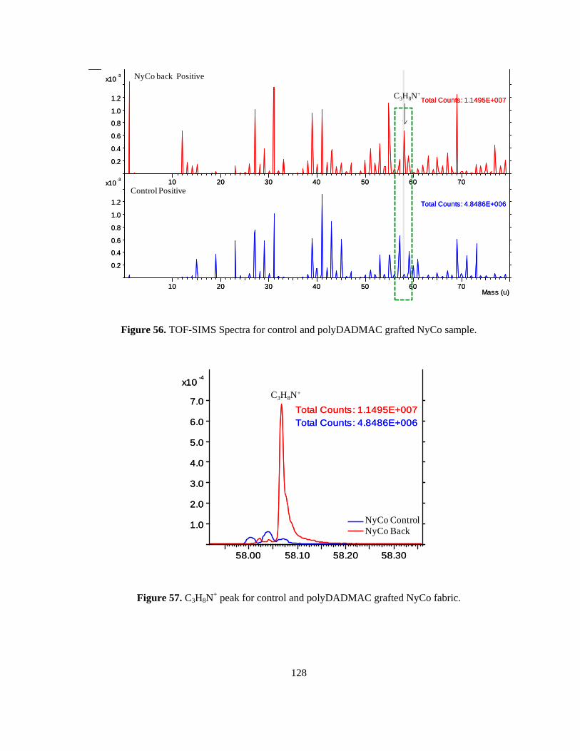
Figure 56. TOF-SIMS Spectra for control and polyDADMAC grafted NyCo sample. ....... 128
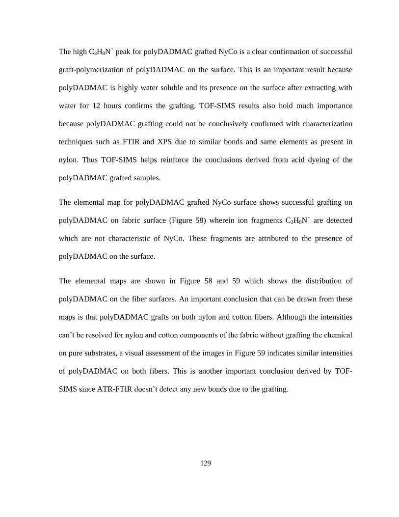
Figure 57. C3H8N+ peak for control and polyDADMAC grafted NyCo fabric. ................... 128
Figure 58. TOF-SIMS for control NyCo fabric showing (a-c) characteristic nylon ions
fragments and (d) negligible C3H8N+ ions. ........................................................................... 130
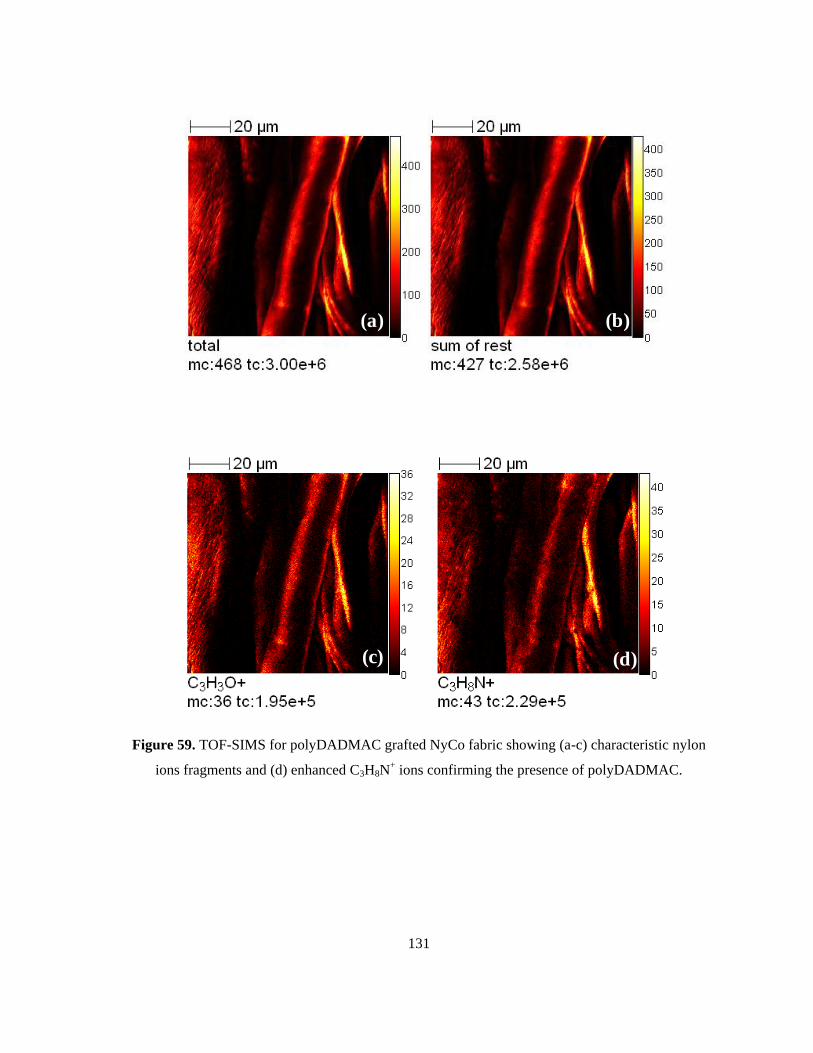
Figure 59. TOF-SIMS for polyDADMAC grafted NyCo fabric showing (a-c) characteristic
nylon ions fragments and (d) enhanced C3H8N+ ions confirming the presence of
polyDADMAC. ..................................................................................................................... 131
Figure 60. TOF-SIMS Negative maps for NyCo Control..................................................... 132
Figure 61. TOF-SIMS maps for polyDADMAC grafted NyCo fabric. ................................ 132
Figure 62. SEM images of control NyCo fabric showing rough cotton fibers and smooth
nylon fibers. .......................................................................................................................... 133
Figure 63. SEM images for polyDADMAC grafted NyCo fiber surfaces. .......................... 134
Figure 64. Free radical polymerization mechanism for plasma induced graft polymerization
of TG-30................................................................................................................................ 135
Figure 65. Process map for one plasma step graft polymerization of DADMAC and TG-30.
............................................................................................................................................... 136
Figure 66. Free radical mechanism for reaction between TG-30 and diethylene ................. 138
Figure 67. Contact angle measurements for 10 microliter water and n-dodecane droplet. .. 140
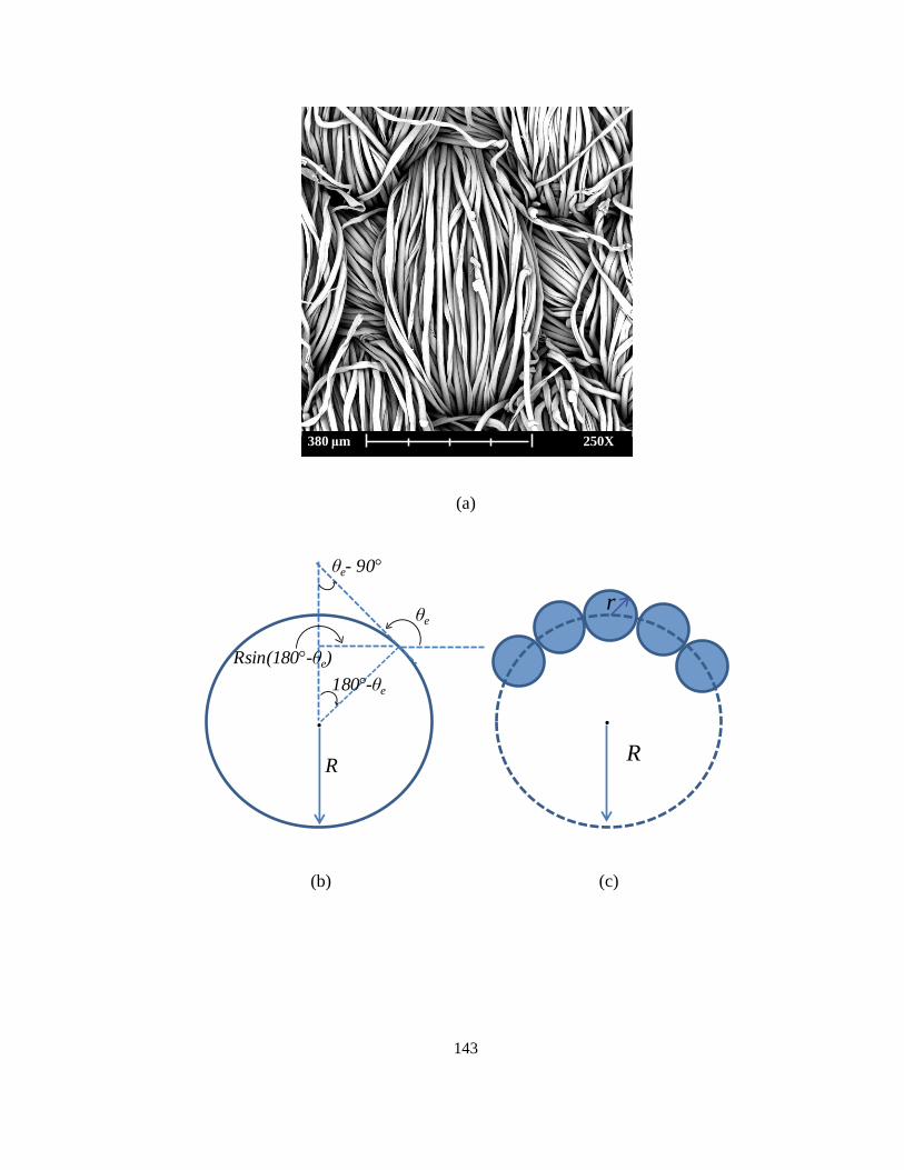
Figure 68. (a) SEM image of the compact NyCo structure, (b) yarn assumed as a perfect
round shape, (c) roughness on the yarn surface due to fibers. .............................................. 142
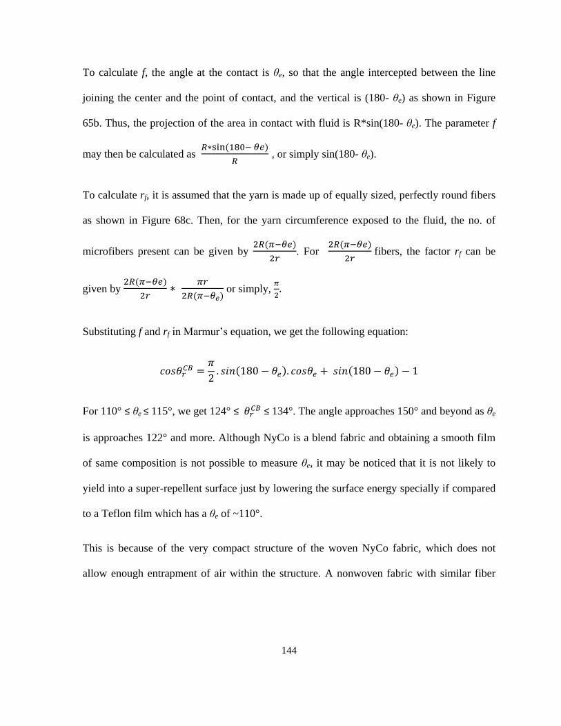
Figure 69. A comparison between the compact structure of NyCo surface and a nonwoven
fabric surface. ........................................................................................................................ 145
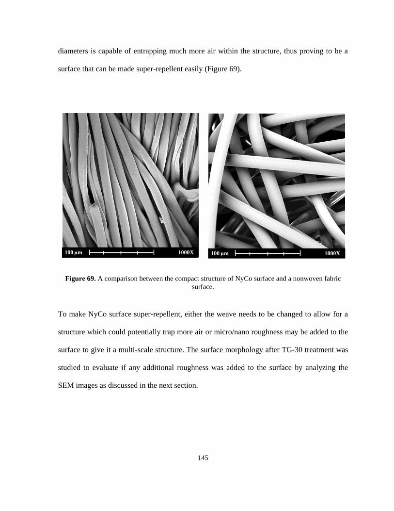
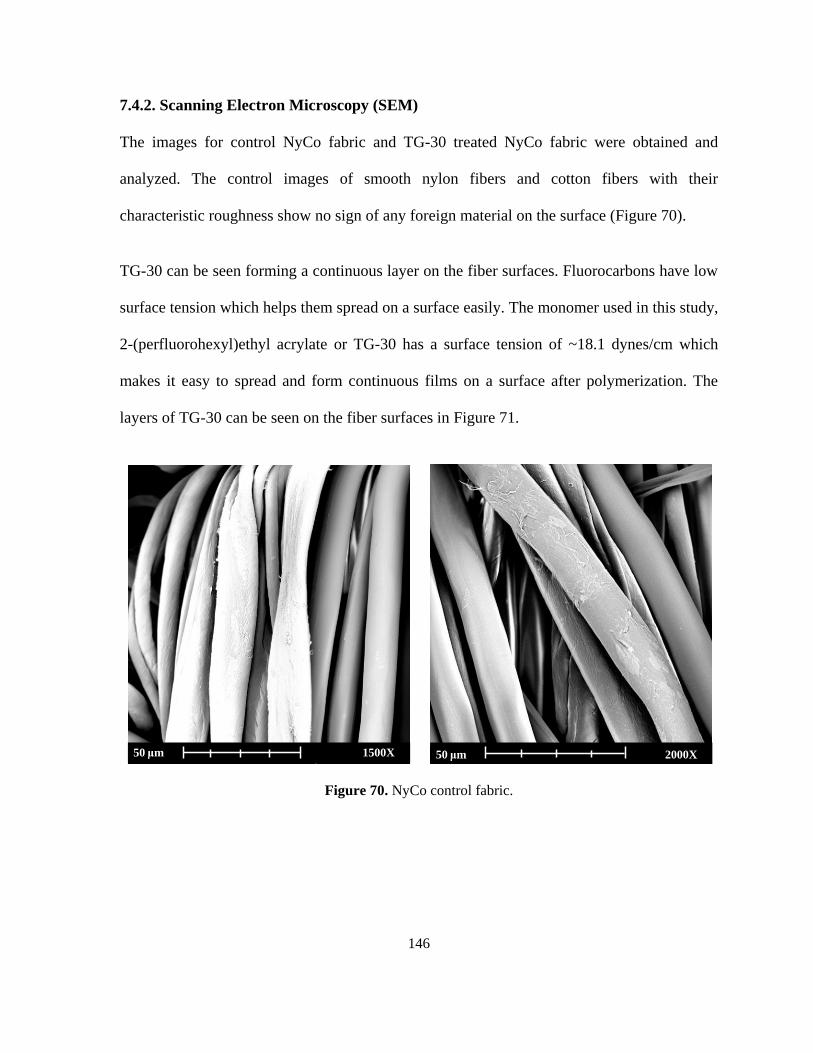
Figure 70. NyCo control fabric. ............................................................................................ 146
Figure 71. NyCo fabric grafted with TG-30 polymer. .......................................................... 147
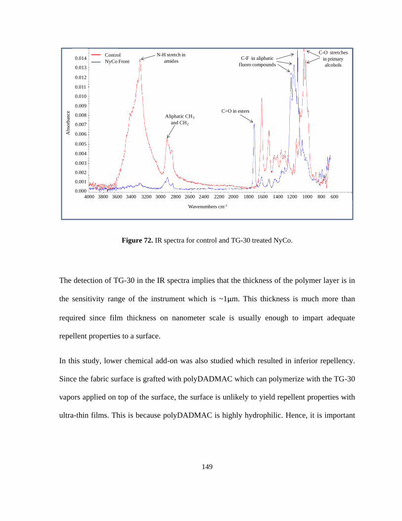
Figure 72. IR spectra for control and TG-30 treated NyCo. ................................................. 149
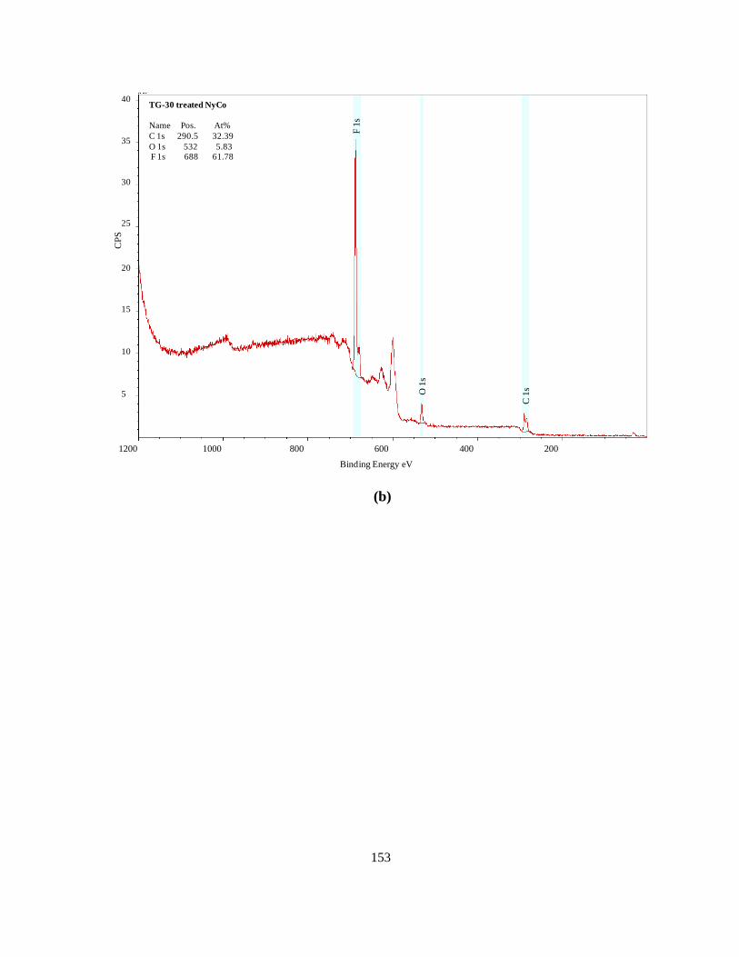
Figure 73. XPS spectra for (a) NyCo control and (b) TG-30 trated NyCo surface. ............. 151
Figure 74. TOF-SIMS spectra for control and TG-30 treated NyCo fabric. ........................ 155
Figure 75. TOF-SIMS negative ion fragment mapping for control NyCo. .......................... 156
Figure 76. TOF-SIMS mapping for negative ions indicating intense fluorine maps for TG-30
treated NyCo fabric. .............................................................................................................. 157
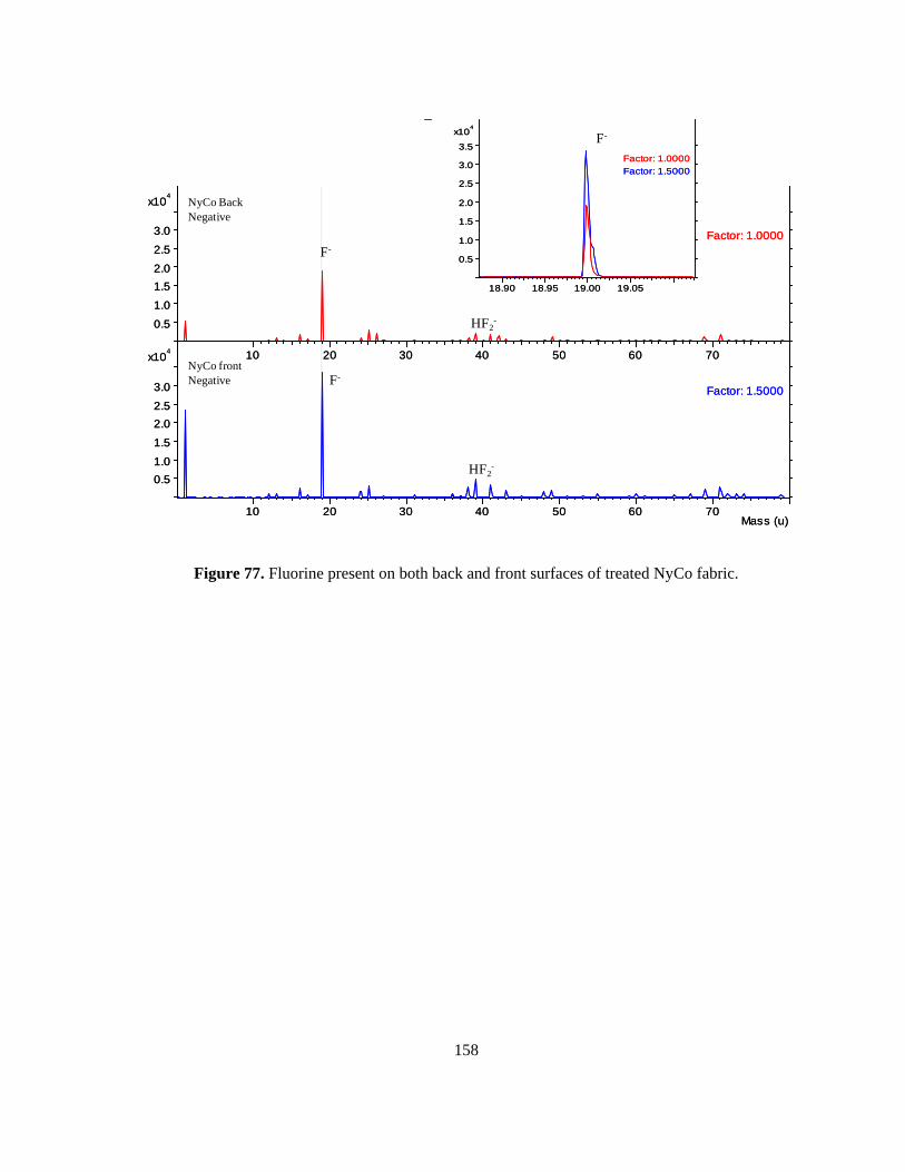
Figure 77. Fluorine present on both back and front surfaces of treated NyCo fabric. .......... 158
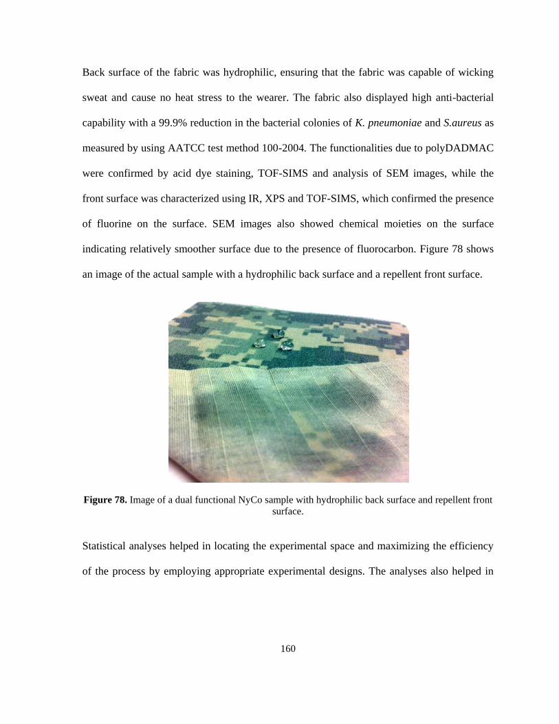
Figure 78. Image of a dual functional NyCo sample with hydrophilic back surface and
repellent front surface. .......................................................................................................... 160
Page 14
xi
LIST OF TABLES
Table 1. Estimated casualties in World War I ......................................................................... 6
Table 2. Effects of CBWAs ..................................................................................................... 8
Table 3. Dermal exposures to nerve agent required for lethality to humans .......................... 11
Table 4. Effects of various warfare agents ............................................................................. 16
Table 5. Plasma catrgorization ............................................................................................... 62
Table 6. Properties of atmospheric discharges ....................................................................... 69
Table 7. Chemistry in a plasma system .................................................................................. 73
Table 8. AATCC 193-2007 Standard test liquids ................................................................... 98
Table 9. AATCC test method 118-2007 ratings ..................................................................... 99
Table 10. Parameter levels for screening experiments for thermal graft-polymerization of
DADMAC on NyCo ............................................................................................................. 101
Table 11. ANOVA table for thermal graft polymerization DADMAC ................................ 101
Table 12. Charge densities obtained for polyDADMAC grafted NyCo fabric samples ...... 103
Table 13. Factor levels for plasma induced graft-polymerization of DADMAC on NyCo
experiments ........................................................................................................................... 105
Table 14. ANOVA table for screening DoE ......................................................................... 105
Table 15. Parameter estimates for screening DoE ................................................................ 105
Table 16. Parameter level for plasma induced graft polymerization of TG-30 on NyCo
experiments ........................................................................................................................... 109
Table 17. ANOVA table for TG-30 DOE ............................................................................. 109
Table 18. Parameter estimatesfor TG-30 DOE ..................................................................... 109
Table 19. Factor combinations for DADMAC grafting on NyCo ........................................ 115
Table 20. Amount of DADMAC grafted onto the fabric measured stoichiometrically using
absorbance data from visible spectrophotometry ................................................................. 116
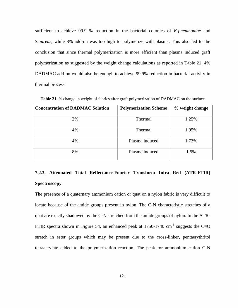
Table 21. % change in weight of fabrics after graft polymerization of DADMAC on the
surface ................................................................................................................................... 121
Table 22. Surface elemental compositions for control and polyDADMAC grafted NyCo
samples measured through XPS............................................................................................ 127
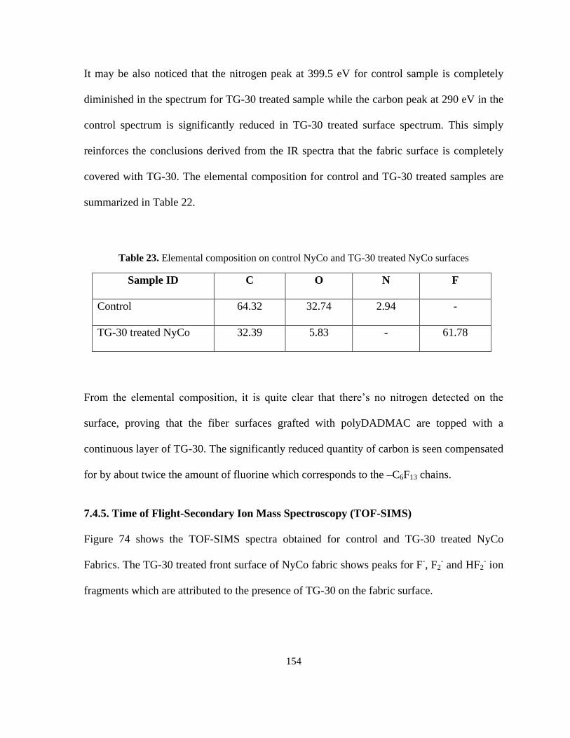
Table 23. Elemental composition on control NyCo and TG-30 treated NyCo surfaces ....... 154
Page 15
1
CHAPTER 1
INTRODUCTION
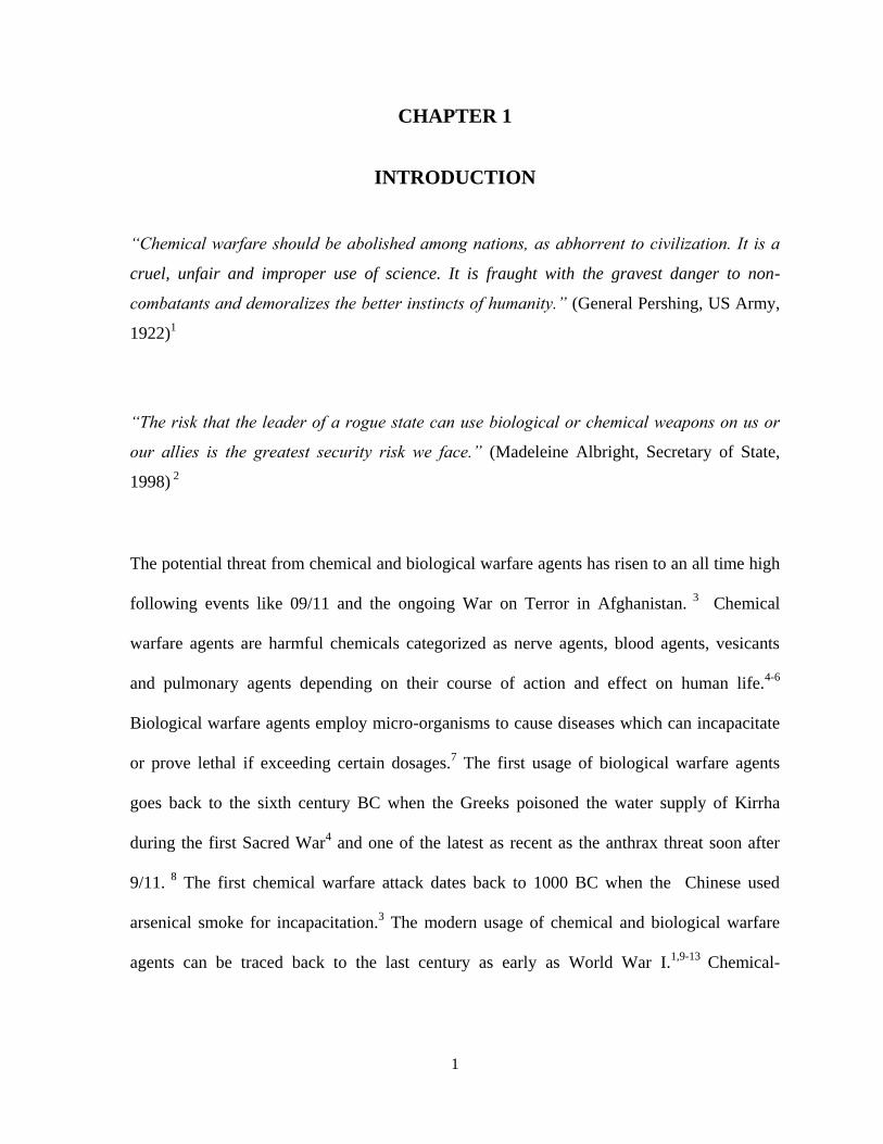
“Chemical warfare should be abolished among nations, as abhorrent to civilization. It is a
cruel, unfair and improper use of science. It is fraught with the gravest danger to non-
combatants and demoralizes the better instincts of humanity.” (General Pershing, US Army,
1922)1
“The risk that the leader of a rogue state can use biological or chemical weapons on us or
our allies is the greatest security risk we face.” (Madeleine Albright, Secretary of State,
1998) 2
The potential threat from chemical and biological warfare agents has risen to an all time high
following events like 09/11 and the ongoing War on Terror in Afghanistan. 3
Chemical
warfare agents are harmful chemicals categorized as nerve agents, blood agents, vesicants
and pulmonary agents depending on their course of action and effect on human life.4-6
Biological warfare agents employ micro-organisms to cause diseases which can incapacitate
or prove lethal if exceeding certain dosages.7 The first usage of biological warfare agents
goes back to the sixth century BC when the Greeks poisoned the water supply of Kirrha
during the first Sacred War4 and one of the latest as recent as the anthrax threat soon after
9/11. 8
The first chemical warfare attack dates back to 1000 BC when the Chinese used
arsenical smoke for incapacitation.3 The modern usage of chemical and biological warfare
agents can be traced back to the last century as early as World War I.1,9-13
Chemical-
Page 16
2
biological warfare agents (CBWAs) were used in all capacities during the war. Early in the
war, the Germans used chlorine and phosgene to incapacitate their opponents and later came
up with more sophisticated and tailored agents such as the mustards.4,14,15
This was followed
by a considerable research in CBWAs and protection strategies by the Germans as well as the
allies including equipment, decontamination and treatment among others.
Most CBWAs are oily liquids with low surface tensions and varying volatilities.16-18
Due to
low surface tensions, these oils easily wet any untreated textile surface and penetrate to the
skin. Low volatilities leading to long lifetimes allow the CBWAs stay on a surface for
prolonged periods of time resulting in severe threats to health and life. The design of an
effective protective covering must include functionalities to provide a super-repellent action
to repel the CBWAs as much as possible and self-decontaminating ability to protect from the
residuals. The current military uniform comprises of a repellent nylon-cotton shell. It has a
liner with a non-woven front, laminated to activated carbon spheres and bonded to a knitted
back that adsorbs chemical vapor agents. This uniform was designed by the Joint Services
Lightweight Integrated Suit Technology program (JSLIST), specially created in 1997 to
design and develop CBWAs protective uniforms.19,20
The JSLIST program strives to create
better, lighter and more functional uniforms for more effective protection for the soldiers in
extreme environments. Adding more layers to the protective uniform is not an option because
it adds to the overall weight, reduces comfort, and hampers movement and senses. The
current need is to create a multi-functional surface with added protection, comfort and
durability.
Page 17
3
Plasma is one of the most sophisticated technologies currently employed by the Defense
Science and Technology Laboratories to create super-repellent surfaces by treating finished
products with vacuum plasma. 21
Plasma is also shown to successfully graft a variety of
chemicals onto textile surface by a free-radical mechanism.22-28
The aim of this work is to
enhance functionality and durability of the nylon-cotton uniform shell by incorporating
super-repellent and self-detoxifying chemistries via atmospheric plasma treatment. This
study is focused on plasma induced graft polymerization of a C6 monomer, 2-
(perfluorohexyl) ethyl acrylate to impart super-repellency and a diallyldimethylammonium
chloride (DADMAC) monomer to induce self-detoxifying capabilities to the fabric. Although
several studies have been published on creating super-repellent textile surfaces29-33
and self-
detoxification via DADMAC chemistry, having these two chemistries on the two sides of a
substrate for enhanced protection is a new approach. Plasma processing is not only fast, it is
also environmentally friendly, sustainable, and cost-efficient in the long run. In addition,
plasma is extremely surface specific which provides opportunities to treat each side of a
substrate with different chemical capabilities.
This study first presents an in-depth literature review on chemical-biological warfare agents,
their properties and threats. The review also covers the concept of super-repellency and a
detailed discussion on the various characterization parameters is given. Parameters such as
contact angle, surface modeling and the chemistries utilized have evolved in recent years.
This is then followed by a report on self-detoxification chemistry and the work done by
several research groups to create and apply a variety of monomers for this specific purpose.
Finally, plasma technology is discussed in detail and the study is focused on the
Page 18
4
incorporation of plasma to induce the suggested functionalities onto the nylon-cotton textile
for application in military uniforms.
Page 19
5
CHAPTER 2
CHEMICAL BIOLOGICAL WARFARE AGENTS: A BRIEF HISTORY
AND THREATS IN THE CURRENT SCENARIO
2.1. Chemical-Biological warfare agents: A brief history
Chemical/biological warfare agents are weapons used to kill or injure human life, livestock,
or plants.34,35
Chemical warfare agents are poisonous chemicals whereas biological warfare
agents include pathogens or micro-organisms such as bacteria, fungi and viruses that may
cause diseases. The first use of CBWAs can be traced back to 6th
century BC. However, full
usage of modern chemical-biological warfare agents occurred during World War I. The
Germans first used phosgene and chlorine and later developed much more serious agents
such as the „mustard‟, so called due to its sharp, garlic like odor. The French developed a
tear gas grenade containing ethyl bromoacetate and other riot-control agents. The first large-
scale use of chemicals was initiated and commercialized by Germany. The operation was
headed by Fritz Haber, the winner of 1918 Nobel Prize in Chemistry for his contribution
developing a process for ammonia synthesis. On April 22, 1915, chlorine was used against
the Allied forces causing hundreds of deaths. The Allies quickly adapted to the advances and
developed their own warfare with chlorine and phosgene. The year 1917 saw the
development of mustard in Germany. Compared to the first set of chemical warfare agents,
mustard was much more persistent and was able to contaminate air, ground and water with
equal severity. Mustard injuries are slow to heal. Although mustard did not cause as many
deaths, it overwhelmed the medical system, greatly paralyzing the Allies. The magnitude
Page 20
6
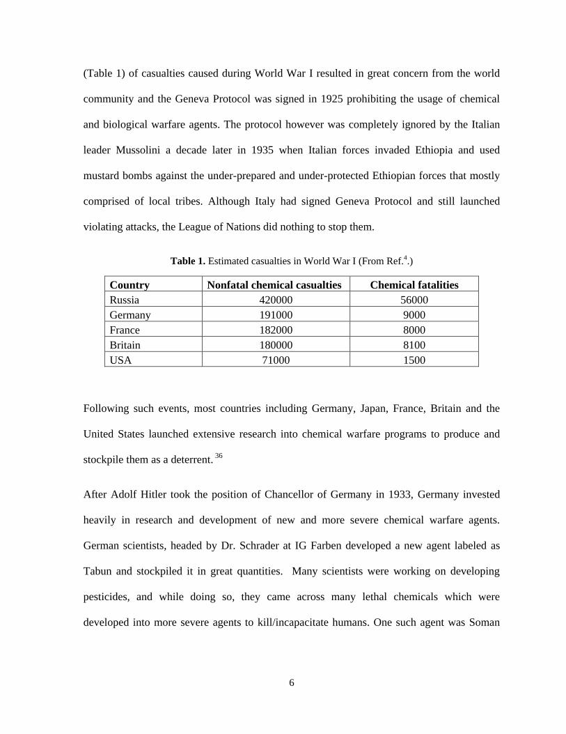
(Table 1) of casualties caused during World War I resulted in great concern from the world
community and the Geneva Protocol was signed in 1925 prohibiting the usage of chemical
and biological warfare agents. The protocol however was completely ignored by the Italian
leader Mussolini a decade later in 1935 when Italian forces invaded Ethiopia and used
mustard bombs against the under-prepared and under-protected Ethiopian forces that mostly
comprised of local tribes. Although Italy had signed Geneva Protocol and still launched
violating attacks, the League of Nations did nothing to stop them.
Table 1. Estimated casualties in World War I (From Ref.4.)
Country Nonfatal chemical casualties Chemical fatalities
Russia 420000 56000
Germany 191000 9000
France 182000 8000
Britain 180000 8100
USA 71000 1500
Following such events, most countries including Germany, Japan, France, Britain and the
United States launched extensive research into chemical warfare programs to produce and
stockpile them as a deterrent. 36
After Adolf Hitler took the position of Chancellor of Germany in 1933, Germany invested
heavily in research and development of new and more severe chemical warfare agents.
German scientists, headed by Dr. Schrader at IG Farben developed a new agent labeled as
Tabun and stockpiled it in great quantities. Many scientists were working on developing
pesticides, and while doing so, they came across many lethal chemicals which were
developed into more severe agents to kill/incapacitate humans. One such agent was Soman
Page 21
7
developed by Richard Kuhn. During the decisive World War II, the fear of chemical warfare
agents among the Allied forces was great, but Germany did not employ newly invented
agents due to the threat of retaliation. Sometimes, this is also attributed to Hitler‟s own
encounter with mustard agent during World War I in 1918 which he later mentioned in Mein
Kampf, “my eyes were transformed into glowing coals and the world had grown dark around
me”. 37
Although Hitler recovered from the attack, he retained the traumatic memories
throughout his life.
Several agents were invented during World War II including a new range of nerve agents,
vesicants, blood agents and choking agents. The threat of chemical biological warfare agents
has reached new heights since many chemical warfare agents can be easily synthesized and
information about the agents, their properties and effects as well as the chemistry behind
them is available in the public domain. In today‟s scenario with events like the Persian Gulf
War (1990-1991) when Iraqi forces resorted to chemical warfare agents, 09/11 (2001) when
there were severe anthrax threats and the current War on Terror (2001 to present) where a
chemical-biological attack on the Allies is not bound by any treaties, it is of utmost
importance to protect military personnel from any potential threats.
2.2. Chemical-Biological warfare agents
The development of chemical-biological warfare agents over the last century has introduced
several extremely lethal agents to mankind. These agents are categorized depending on the
way they affect the human constitution. Most of these agents are gaseous and the rest are oily
liquids with low surface tensions. Table 2 lists the typical effects of CBWAs.
Page 22
8
Table 2. Effects of CBWAs 37
Toxic chemicals
Nerve Affect nervous system, skin, eyes
Blood Prevent oxygen from reaching body tissues
Blister Affect eyes, lungs and skin
Choking Affect nose, throat, and lungs
Psycho-chemical Cause sleepiness
Irritant Cause eye, lung and skin irritations
Vomiting Cause headache, nausea, vomiting
Tear Affect eyes and skin
Micro-organisms
Anthrax Cause pulmonary complications
Plague Cause pneumonic problems
Tularemia Cause fever
Viral encephalitis Affect nervous system
Toxins
Saxiloxin Cause shellfish poisoning
Botulinum A Cause food poisoning
Depending on their effect, chemical warfare agents are classified into nerve agents, vesicant
agents, blood agents and pulmonary agents.
Page 23
9
2.2.1. Nerve agents
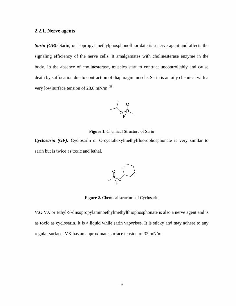
Sarin (GB): Sarin, or isopropyl methylphosphonofluoridate is a nerve agent and affects the
signaling efficiency of the nerve cells. It amalgamates with cholinesterase enzyme in the
body. In the absence of cholinesterase, muscles start to contract uncontrollably and cause
death by suffocation due to contraction of diaphragm muscle. Sarin is an oily chemical with a
very low surface tension of 28.8 mN/m. 38
Figure 1. Chemical Structure of Sarin
Cyclosarin (GF): Cyclosarin or O-cyclohexylmethylfluorophosphonate is very similar to
sarin but is twice as toxic and lethal.
Figure 2. Chemical structure of Cyclosarin
VX: VX or Ethyl-S-diisopropylaminoethylmethylthiophosphonate is also a nerve agent and is
as toxic as cyclosarin. It is a liquid while sarin vaporises. It is sticky and may adhere to any
regular surface. VX has an approximate surface tension of 32 mN/m.
Page 24
10
Figure 3. Chemical structure of VX
Soman (GD): Chemically, Soman is 1,2,2-trimethylpropyl methylphosphonofluoridate.
Soman is a nerve agent and acts similar to Sarin. However, it acts much faster and is as toxic
as Cyclosarin. It has a low surface tension of 24.5 mN/m.
Figure 4. Chemical structutre of Soman
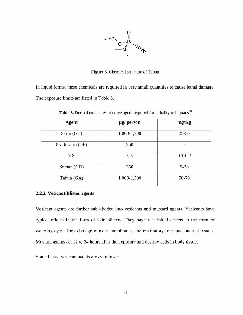
Tabun (GA): Chemically, Tabun is O-ethyl N,N-dimethylphosphoroamidocyanidate and is
classified as a nerve agent. It mixes with water easily and poses potential hazards when
mixed with drinking water. It may enter the human body via inhalation, water and food.
Tabun acts within seconds to few hours depending on the level of exposure. Inside the body,
it prevents normal functioning of muscles and glands and causes paralysis. Under mild
dosages, tabun may result in runny nose, headache, drowsiness, cough, abnormal blood
pressure and heart rate, nausea and rapid breathing. Skin exposure to tabun can cause muscle
twitching and excessive sweating.
Page 25
11
Figure 5. Chemical structure of Tabun
In liquid forms, these chemicals are required in very small quantities to cause lethal damage.
The exposure limits are listed in Table 3.
Table 3. Dermal exposures to nerve agent required for lethality to humans38
Agent µg/ person mg/Kg
Sarin (GB) 1,000-1,700 25-50
Cyclosarin (GF) 350 -
VX < 5 0.1-0.2
Soman (GD) 350 5-20
Tabun (GA) 1,000-1,500 50-70
2.2.2. Vesicant/Blister agents
Vesicant agents are further sub-divided into vesicants and mustard agents. Vesicants have
typical effects in the form of skin blisters. They have fast initial effects in the form of
watering eyes. They damage mucous membranes, the respiratory tract and internal organs.
Mustard agents act 12 to 24 hours after the exposure and destroy cells in body tissues.
Some feared vesicant agents are as follows:
Page 26
12
Lewisite (L): Lewisite or 2-chloroethenyldichloroarsine is an oily colorless liquid in its pure
form. Lewisite acts very fast if exposed to in enough quantities. It causes severe skin
irritation with 10-30 minutes and blister formation within few hours. It may cause irritation,
pain and swelling of eyes. If introduced to the digestive tract, it may cause nausea, diarrhea
and vomiting.
Figure 6. Chemical structure of Lewisite
Mustard-Lewisite: Mustard-Lewisite is a mixture of sulfur mustard and lewisite. It is both a
vesicant and an alkylating agent which affects the DNA structure of the dividing cells.
Mustard-Lewisite may be absorbed by the human body by inhalation, ingestion, direct skin
contact or eye contact.
Figure 7. Chemical structure of Sulfur Mustard
Phosgene oxime: Phosgene oxime or dichloroformoxime (Cl2C=N-OH) belongs to the
vesicants category and causes severe skin itching and irritation upon exposure. It acts similar
to Lewisite and causes eye irritation, skin blisters and respiratory irritation leading to
incapacitation.
Page 27
13
Mustards (HD, HT, H, HL, HQ, HN1, HN2, HN3): Mustards refer to the family of sulfur
(Bis-(2-chloroethyl) sulfide, ClCH2CH2-S-CH2CH2Cl), nitrogen (CH3CH2-N-(CH2CH2Cl)2)
and oxygen based chemical compounds having similar chemical or biological effects. They
are oily liquids with low surface tensions (~42 mN/m) and cause severe corrosive damage by
hydrolyzing to hydrochloric acid (HCl). Mustards are highly lethal and difficult to
decontaminate. Due to their corrosive nature, mustards are able to penetrate many surfaces.
2.2.3. Blood agents
Blood agents are highly volatile, fast acting CWAs which result in cardiac arrest, respiratory
failure and seizures upon exposure. Some feared blood agents are:
Hydrogen cyanide (AC): Hydrogen cyanide (HCN) exists as a liquid at the room
temperature. It has a high volatility and that limits its usage as a weapon to some extent, for it
becomes difficult to acquire high enough concentrations in an attack. However, hydrogen
cyanide is extremely poisonous and exposure to even small concentrations can lead to
damage. Hydrogen cyanide is not considered as a major threat in the modern wars as this
chemical poses numerous problems in carrying out a successful attack on a large scale.
However hydrogen cyanide can be synthesized in a laboratory and is therefore is easier for
terrorists to possess for small scale and localized attacks.
Hydrogen cyanide forms a complex with cytochrome oxidase in blood cells and hampers the
normal oxygen flow. The median lethal concentration (LCt50) of hydrogen cyanide chloride
is estimated to be approximately 5 grams-min/m3.
Page 28
14
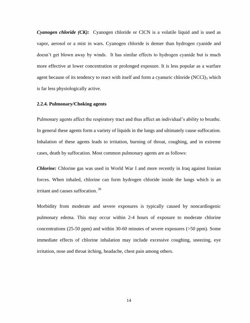
Cyanogen chloride (CK): Cyanogen chloride or ClCN is a volatile liquid and is used as
vapor, aerosol or a mist in wars. Cyanogen chloride is denser than hydrogen cyanide and
doesn‟t get blown away by winds. It has similar effects to hydrogen cyanide but is much
more effective at lower concentration or prolonged exposure. It is less popular as a warfare
agent because of its tendency to react with itself and form a cyanuric chloride (NCCl)3 which
is far less physiologically active.
2.2.4. Pulmonary/Choking agents
Pulmonary agents affect the respiratory tract and thus affect an individual‟s ability to breathe.
In general these agents form a variety of liquids in the lungs and ultimately cause suffocation.
Inhalation of these agents leads to irritation, burning of throat, coughing, and in extreme
cases, death by suffocation. Most common pulmonary agents are as follows:
Chlorine: Chlorine gas was used in World War I and more recently in Iraq against Iranian
forces. When inhaled, chlorine can form hydrogen chloride inside the lungs which is an
irritant and causes suffocation. 39
Morbidity from moderate and severe exposures is typically caused by noncardiogenic
pulmonary edema. This may occur within 2-4 hours of exposure to moderate chlorine
concentrations (25-50 ppm) and within 30-60 minutes of severe exposures (>50 ppm). Some
immediate effects of chlorine inhalation may include excessive coughing, sneezing, eye
irritation, nose and throat itching, headache, chest pain among others.
Page 29
15
Phosgene (CG): Phosgene (COCl2) is commonly used by the chemical industry for a variety
of synthesis processes. Phosgene is low boiling and exists as a gas at room temperature.
Phosgene was first used by the German army in World War I and later by the French,
American and British army as well. 40
Upon inhalation, phosgene hydrolyses to hydrogen
chloride inside the lungs and causes severe damages due to corrosive action. The effects of
phosgene are similar to that of chlorine gas; however phosgene is much stronger at lower
concentration. It has a higher density than air and therefore tends to settle down towards the
ground surface.
Chloropicrin (PS): Chloropicrin or trichloronitromethane (Cl3C-NO2) is an oily, colorless,
low surface tension liquid (46.9 mN/m). An exposure to chloropicrin may lead to irritation of
skin and eyes, coughing, sore throat, labored breathing and pulmonary edema. Chloropicrin
may have an adverse effect on human health even at very small concentrations of 1-20 ppm.
41
Diphosgene (DP): Diphosgene or trichloromethylchloroformate (ClOC-O-CCl3) is also
called a lung-damaging agent for it directly attacks lung tissues causing pulmonary edema. In
the atmosphere, diphosgene rapidly breaks down to phosgene and chloroform. Diphosgene
essentially acts similar to phosgene.7
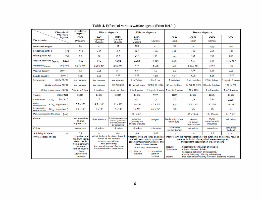
Chemical warfare agents not only penetrate the textile structure easily due to their low
surface tensions, they are only required in small amounts to cause damage (Table 4). Hence,
the challenge is to create a surface with sufficient repellency.
Page 30
16
Table 4. Effects of various warfare agents (From Ref.41.)
Page 31
17
Some feared biological warfare agents are as follows42
:
Ebola virus: This virus spreads through direct contact with the skin and takes about a week
to kill the victim.
Botulinum toxin: The Clostridium botulinum bacteria produce this toxin, which spreads
through direct skin contact and requires only very small quantities for a fatal attack. It acts
like a nerve agent and inhibits chemical release in nerve cells which restricts muscle
contractions and ultimately causes paralysis.
Anthrax: Anthrax bacteria may enter the body through direct inhalation or through cuts or
opening in the skin. It causes fever, severe headache, vomiting, weakness, difficult breathing,
and finally death.
Tularemia: This bacterium causes respiratory illness and high fever. Although medicinal
cure for tularemia exists, it doesn‟t shorten the course of the disease which largely causes
incapacitation.
In a typical war scenario, these CBWAs are spread through air by way of bomb or missiles,
which may spread the chemical over a wide area. These agents may also be sprayed directly
by an aircraft over a city or for smaller attacks, aerosol canisters may be used in crowded
areas for maximum disruptions. When a chemical weapon is put into use, it forms a cloud of
solid or liquid aerosol, known as the primary cloud (Figure 8). This cloud then lands onto
individuals or the ground causing ground contamination, water contamination or damage to
Page 32
18
human life by direct contact. The chemical on the ground may evaporate and form secondary
clouds; hence ground contamination has a limited lifetime. 43
Figure 8. Chemical weapon detonation (From Ref.43.)
Factors increasing the danger of the primary cloud may be listed as follows:
Steady wind direction
Wind velocity under 3 ms-1
Stable air (inversion)
Temperature above 20ºC
No precipitation
Page 33
19
Figure 9. Effect of primary cloud with respect to wind velocity (From Ref.43.).
The chemical contamination disappears as the CWA reacts chemically or is diluted below
toxic levels by physical action. Chemical reactions that help dilute the persistence of agent in
the environment include:
Hydrolysis with water in the environment
Photochemical reactions with sunlight
Thermochemical decomposition
Other reactions with compounds present in the environment
The approximate lifetime of chemical contamination on ground is calculated through
complex methods. The information of the local climate is gathered and factors such as
temperature, rainfall, solar flux etc. are taken into account for the same. The approximate
Page 34
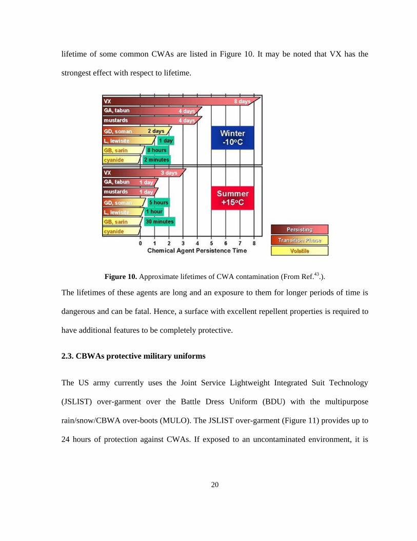
20
lifetime of some common CWAs are listed in Figure 10. It may be noted that VX has the
strongest effect with respect to lifetime.
Figure 10. Approximate lifetimes of CWA contamination (From Ref.43.).
The lifetimes of these agents are long and an exposure to them for longer periods of time is
dangerous and can be fatal. Hence, a surface with excellent repellent properties is required to
have additional features to be completely protective.
2.3. CBWAs protective military uniforms
The US army currently uses the Joint Service Lightweight Integrated Suit Technology
(JSLIST) over-garment over the Battle Dress Uniform (BDU) with the multipurpose
rain/snow/CBWA over-boots (MULO). The JSLIST over-garment (Figure 11) provides up to
24 hours of protection against CWAs. If exposed to an uncontaminated environment, it is
Page 35
21
durable for 45 days and can be laundered for 6 times. If the suit is not laundered, it may be
used for 120 days in an uncontaminated environment. The outer shell of this garment is a
50/50 nylon/cotton poplin blend with a rip-stop weave with a water-repellent finish. The liner
layer is a nonwoven layer with activated carbon spheres to provide for vapor adsorption.
Carbon spheres have replaced the previously used bulky charcoal impregnated polyurethane
foam and nylon tricot laminate.19,44
Figure 11. JSLIST with a chemical protection mask (From Ref.44.).
Another technology developed by UK‟s Defense Science and Technology Laboratory
(DSTL) and licensed by P2i Ltd. is a great example of imparting super-repellency to military
Page 36
22
textile via plasma treatment. This technology is based on a batch treatment process which
uses a 2000 L stainless steel chamber with internal capacitively coupled electrodes (Figure
12). The biggest advantages of the process include the ability to treat finished products with a
high degree of homogeneity, fast processing, clean and environmentally friendly runs among
others.45,46
Figure 12. P2i Ltd's 2000L plasma chamber (From Ref.46.).
Page 37
23
CHAPTER 3
MULTIFUNCTIONAL MILITARY TEXTILE: SUPER-REPELLENCY
AND SELF-DETOXIFICATION
3.1. Super-repellency: Surface tension approach
3.1.1. Contact angle on a smooth surface
Super-repellency of a solid surface is defined as its extra-ordinary ability to repel liquids.
Most researchers have defined the term „super-repellency‟ of a solid surface as its ability to
demonstrate a contact angle with a liquid droplet to be more than 150º and a small roll off
angle. 47,48
In addition, contact angle hysteresis is also used to characterize the repellent
properties of a surface. The phenomenon of super-repellency has been largely studied over
the last seven decades. Super-repellency on synthetic surfaces was developed in an attempt to
mimic the lotus leaves which have high repellency to water droplets. Not only is the contact
angle between water and a lotus leaf more than 150º, the roll off angle is small also. Due to
the combination of these two parameters, lotus leaves possess self-cleaning action i.e., when
a water droplet rolls off the surface, it carries away any dirt present on the surface thus
leaving the surface clean.
A super-repellent surface is characterized by two main parameters: contact angle and contact
angle hysteresis. Contact angle is the angle between the surface and a tangent drawn on the
droplet meniscus resting on the surface. The contact angle on a smooth surface can be
calculated by Young‟s equation:
Page 38
24
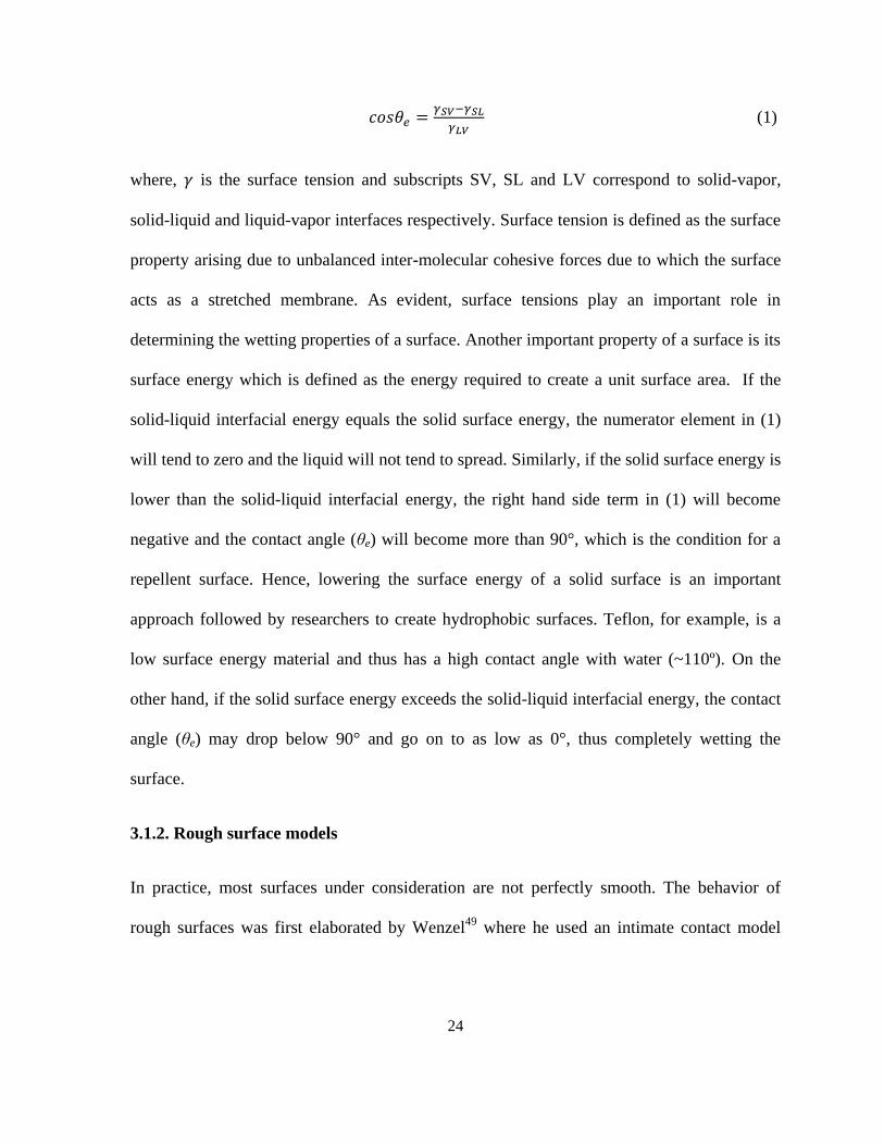
(1)
where, is the surface tension and subscripts SV, SL and LV correspond to solid-vapor,
solid-liquid and liquid-vapor interfaces respectively. Surface tension is defined as the surface
property arising due to unbalanced inter-molecular cohesive forces due to which the surface
acts as a stretched membrane. As evident, surface tensions play an important role in
determining the wetting properties of a surface. Another important property of a surface is its
surface energy which is defined as the energy required to create a unit surface area. If the
solid-liquid interfacial energy equals the solid surface energy, the numerator element in (1)
will tend to zero and the liquid will not tend to spread. Similarly, if the solid surface energy is
lower than the solid-liquid interfacial energy, the right hand side term in (1) will become
negative and the contact angle (θe) will become more than 90°, which is the condition for a
repellent surface. Hence, lowering the surface energy of a solid surface is an important
approach followed by researchers to create hydrophobic surfaces. Teflon, for example, is a
low surface energy material and thus has a high contact angle with water (~110º). On the
other hand, if the solid surface energy exceeds the solid-liquid interfacial energy, the contact
angle (θe) may drop below 90° and go on to as low as 0°, thus completely wetting the
surface.
3.1.2. Rough surface models
In practice, most surfaces under consideration are not perfectly smooth. The behavior of
rough surfaces was first elaborated by Wenzel49
where he used an intimate contact model
Page 39
25
(Figure 13.b) while working on waterproofing open fabric structures. He suggested that the
physical condition of a surface had a far more pronounced effect on its repellency properties
than could be explained by Young‟s equation which takes into account a fixed property of
the associated substances, viz. surface tension. The idea was based on the simple assertion
that on a unit area of rough surface, there is more surface area and therefore, greater surface
energy intensity compared to a unit area on a smooth surface. He introduced a roughness
factor r in the Young‟s model (Figure 13.a) and proposed his version of Young‟s equation as:
(2)
where, roughness factor r =
Since actual surface area is larger than the geometric surface area, r > 1.
Page 40
26
(a) (b) (c)
(d)
Figure 13. (a) Young's model for smooth surfaces, (b) Wenzel's model for rough surface and intimate
contact between liquid and solids (c) Cassie-Baxter's model for porous materials and (d) Marmur's
modification for Cassie-Baxter model.
This equation is more general and reverts to Young‟s equation when the surface is smooth
since r = 1 for a smooth surface. Wenzel‟s model successfully explained hydrophilic surfaces
exhibiting smaller contact angles and hydrophobic surfaces exhibiting larger contact angles
for rough surfaces compared to smooth surfaces of the same material. Figure 14 depicts
contact angles for rough surfaces as a function of roughness factor for corresponding smooth
surfaces.
Page 41
27
Figure 14. Contact angle for rough surface (θ) as a function of roughness factor (r) for smooth
surfaces with various Young's contact angles (From Ref. 50 .).
Another widely accepted and famous model for rough surfaces was suggested by Cassie and
Baxter51
in early 1940s which is based on a porous surface wherein water doesn‟t completely
wet the surface and instead sits on the surface with large packets of air, thus providing a
composite air-solid-liquid interface (Figure 13c). A porous surface is different from a rough
surface as porous surfaces have much deeper pores or irregularities which are interconnected
to each other like channels through which diffusion can take place. 52
The original Cassie-
Baxter equation for contact angle was given as:
(3)
where, f1= fraction of area in contact with liquid and f2= fraction of area in contact with air.
Marmur53
indicated that not only will this surface have air voids; it is takes into account that
the fraction of surface in contact with liquid would have its own roughness analogous to
Page 42
28
Wenzel model (Figure 13d). The Cassie-Baxter equation was thus modified to incorporate
the roughness effect as:
(4)
where, f is the fraction of the projected area in contact with liquid and rf is the roughness
ratio of the wet part f.
The process of wetting involves change in solid-air, solid-liquid and liquid-air interfacial
areas accompanied by a change in the net energy of the system. Wetting thus is a
thermodynamic process and the extent of wetting is determined by the thermodynamic
feasibility. As explained by Wenzel, for a rough surface which is also hydrophilic, there will
be a greater decrease in net free energy and therefore, more spreading will take place. On the
other hand, for a hydrophobic rough surface, the drop will acquire a more spherical shape
leading to a greater decrease in the net free energy. This state is a typical Cassie-Baxter state.
Koishi et. al54
suggest that a transition from meta-stable Cassie-Baxter state to Wenzel state
will take place only if the process in spontaneous. The two states are separated by a free-
energy barrier ΔG as shown schematically in Figure 15. If the free-energy barrier is
considerably high, a surface may remain in Cassie-Baxter state for prolonged periods.
Page 43
29
Figure 15. Free-energy barrier separating the meta-stable Cassie-Baxter state from Wenzel state
(From Ref. 55.).
The transition of Cassie-Baxter state to Wenzel state may be determined in terms of a critical
contact angle θC given by:
=
(5)
Where, f is the fraction of the projected area in contact with liquid; rf is the roughness ratio of
the wet part f and r is the overall roughness ratio.
This equation suggests that when Young‟s contact angle θe > θC > 90º, a surface will exhibit
meta-stable Cassie-Baxter state which will have a free-energy lower than the Wenzel state.56
The transition from Cassie to Wenzel state is important since there is a vast difference
between the adhesion properties. It is well known that the droplet is pinned to the surface in a
Page 44
30
Wenzel state due to intimate contact and hence the repellency is affected. For a
superhydrophobic surface design, θC must be as small as possible since Cassie state is
stabilized at θ > θC (Figure 16). This condition is easier to fulfill at large values of r. 56
Figure 16. Transition between Cassie-Baxter and Wenzel models (From Ref. 57.).
2.2. Contact angle hysteresis
The second very important and often underestimated parameter used to characterize a
repellent surface is contact angle hysteresis. Contact angle hysteresis (ΔθH) is defined as the
difference between advancing (θA) and receding (θR) contact angles. If liquid is added to a
carefully placed droplet on a surface using a syringe, the droplet volume and contact angle
increase. The volume of the droplet expands as the same contact area is maintained until the
contact line advances. The angle at which the contact line advances is the advancing contact
Page 45
31
angle θA. Similarly, if volume of liquid is withdrawn from the drop, the drop begins to
contract maintaining the same contact area until the contact line starts to recede at an angle θR
or the receding contact angle.
Both advancing and receding contact angles are characteristic of the surface chemistry and
the surface topography. According to Gao and McCarthy58
, a meta-stable droplet may be
formed on the surface with a contact angle between θR and θA. Hence, characterization of a
super-repellent surface is not possible through contact angle alone and therefore, both
advancing and receding contact angles in addition to the static meta-stable contact angle must
be reported for a complete characterization.
Contact angle hysteresis is a direct measure of the repelling ability of a surface and actually
responsible for controlling the liquid movement on the surface. A self-cleaning surface is so
called due to its very low hysteresis. Self-cleaning takes place when the liquid moves on the
surface collecting dust and other impurities, leaving the surface clean as depicted in Figure
17(a). This movement cannot be explained by a high contact angle alone.59-61,
Many
researchers have defined a super-repellent surface as a surface exhibiting apparent contact
angle > 150º and contact angle hysteresis < 5º.
Page 46
32
(a) (b)
Figure 17. (a) Contact angle hysteresis and self-cleaning on a super-repellent surface (Adapted from
Ref.51.) and (b) droplet on a tilted plane.
The sliding angle or the tilt angle at which droplet sitting on the top of a surface begins to
move is a function of advancing and receding contact angles and is determined as
(6)
Where m is the mass of the drop and g is acceleration due to gravity. Figure 17(b) depicts a
droplet on an inclined surface. The way a liquid droplet moves on a super-repellent surfaces
determines its self-cleaning ability. The droplet may assume a sliding or skidding motion,
where the droplet bulk remains stationary with respect to itself as a frame of reference and
only the molecules near the contact surface are exchanged with the interfacial molecules. The
droplet may also assume a rolling motion similar to that of a car tire rolling on the road. Or
Page 47
33
the droplet may move in a motion as a combination of the two motions mentioned above.
The type of motion that a droplet would assume depends to a large extent on the surface
topology and hence, the contact line. An important factor affecting the contact angle
hysteresis is „contact line pinning‟. Contact line pinning refers to the immobilization of
contact line due to acute edges or kinks in the surface topology.60,61
As a result of pinning,
the droplet tends to stay at rest even at an inclined plane. When inclined, the shape of the
droplet distorts due to its weight. Due to different contact angles at the two ends of the
droplet, there exists a Laplace pressure difference between the two curvatures (front and
rear) and thus a resisting force develops which can counter gravity for small droplets and
restricts the droplet motion completely. The effect of surface texture towards creating a
super-repellent surface has been studied and presented by many researchers.50,51,62,63
In their
work on contact angle hysteresis, Quere and Reyssat64
suggest that when the drop starts
moving on an inclined plane, the force arising from the hysteresis is countered by the droplet
weight and the sliding angle is given by:
(7)
The underlying assumption behind equation (7) is that half the contact line joins the solid
surface with advancing contact angle (θA) and the rest of the half joins it with the receding
contact angle (θR). The only difference between equations (6) and (7) is that the contact line
is not considered in the former. It must be noted that only half the contact line is considered
in equation (7) ( because the hysteresis is largely due to the trailing end of
Page 48
34
the drop and hence, the contribution from the leading half of the contact line is neglected.
The energy corresponding to a movement of the contact line thus is a result of pinning and
de-pinning of the contact line as it progresses forward. As noted by Wang et al. 65
, the contact
line moves outward or inward until the contact angle reaches the advancing or receding
contact angle in order to achieve the minimum free energy state of equilibrium. It must be
noted that small scale rough texture on the surface can give rise to a much enhanced
accumulated line energy due to a huge number of composite air-solid-liquid interfaces. 66
Evidently, the line energy accumulated per texture would depend on the shape of the texture
and hence complex shape may add significantly to the line energy and consequently result in
a higher hysteresis. On the other hand, the hysteresis would be minimized for rounded
texture. This forms the underlying concept of re-entrant surfaces which is discussed later.
The rolling motion of the droplet is determined completely by the receding tail of the droplet.
In contrast to the advancing motion, the receding motion is associated with an energy barrier
and hence, dewetting is actually the rate determining process for a moving droplet. The
motion of contact line would depend on the contact line at the receding tail and the chemical
heterogeneity of the surface. 67
In the past, many researchers have voiced their opinions
which counter the classic Cassie-Baxter and Wenzel models which depend on the areal
considerations. Extrand published a very notable work in which he prepared chemically
heterogeneous surfaces and showed that when the heterogeneity is completely contained by a
liquid droplet, the contact angle exhibited by it is the same as the droplet on a corresponding
smooth surface. 68
This suggested that the contact angle depends on the three-phase contact
Page 49
35
line and not the area beneath the droplet. This finding was reinforced with other experimental
studies.62
However, the original Cassie and Wenzel models, though challenged heavily61,69,70
, are applicable to surfaces if certain restrictions are borne in mind. The applicability must be
restricted to surfaces with constant roughness and surface fraction parameters.70
Choi et al.66
studied the effect of anisotropic textured surfaces on contact angle hysteresis and concluded
that contact angle hysteresis is a function of topography and connectivity of the surface
micro-texture and is not directly influenced by global areal fraction of liquid-air interface
occluded by the texture. This is an important finding for designing a super-repellent surface
which should have disconnected features and rounded topography.
The idea of a composite air-solid-liquid interface is widely used by researchers to design and
create surfaces which are super-repellent to even low surface tension fluids. In the past few
years, the focus has been on creating hierarchical, re-entrant structures to have a modeled
surface roughness capable of entrapping air, thus enhancing the apparent contact angle.
3.3. Modeling of Rough Super-repellent Surfaces
The hierarchical structures on repellent surfaces were identified and employed as the
responsible reason behind a great performance by many researchers. Gao and McCarthy
reported preparation of an artificial lotus leaf surface by treating microfiber polyester fibers
with a water repellent silicone coating. They suggested the binary scale topography of the
microfibers as the responsible factor behind de-pinning of receding contact line and hence, a
superior performance.61
Lee and Michielsen developed a superhydrophobic surface by
Page 50
36
modeling nylon 6,6 multifilament woven fabric grafted with a low surface tension material,
1H, 1H-perfluorooctylamine.71
Brewer and Willis developed a hierarchical structure based on
a plasma polymerized fluoroacrylate monomer. 72
Leng et al. developed a superoleophobic
cotton surface by an in-situ Stober reaction to incorporate silica micro-particles followed by
adsorption of silica nano particles to achieve dual scale micro/nano structure. 73,74
Liu et al.
reported a bio-inspired design of super-oleophobic micro/nano hierarchical surface. 75
Ming
et al. developed a super-lyophobic surface based on a multi-length structure by incorporating
raspberry-like particles on a woven fabric surface. 76
Ramos et al. developed super-
oleophobic silicon wafers on which a 400 nm amorphous silica film was grown thermally.
An ion track etching technique was used to create randomly distributed nanometric damaged
zones. The samples were then chemically etched in hydrogen fluoride solution and then
grafted with perfluorooctyltrichlorosilane. The internal walls of the cones are reported to
have a screw structure which was responsible to trap air to generate a meta-stable CB state. 77
Most theoretical models suggested by various scientists and researchers depend on either
capillary force or the free energy model. The capillary force model is based on the force
balance between the vertical component of surface tension (γ) and the body forces of the
droplet such as viscous force and gravity. The free energy models are based on the assertion
that the minimum of free energy must indicate the apparent contact angle for a given drop
volume and intrinsic contact angle. The design models are based on creating artificial,
regular and patterned roughness on a surface. The roughness has been modeled in the form of
pillars on a surface. A variety of shapes of pillars are considered with certain geometries. The
Page 51
37
important consideration in selecting the pillar geometries is that of the structure of the contact
line. Oner and McCarthy78
reported a modeled super-repellent surface with square pillar
posts of 2µm x 2µm x 100µm arranged in a hexagonal arrayed pattern. In addition, they also
created staggered rhombus and four arm star shaped posts having different post heights using
photolithography techniques. It was found that the contact angle hysteresis strongly depended
on the shapes of the posts due to the contact line pinning and also to the inter-pillar distance
which regulated the intrusion of liquid into the structure. Barbieri et al. reported a
microstructure Si surface with cylindrical pillars (diameter d = 10 µm, height h= 40 µm and
pitch p= 30 µm) in hexagonal arrangement and showed that all the geometrical parameters, d,
h and p influenced the contact angle. 79
In addition, the effect of pillar top perimeter on the
total length of the contact line due to various shapes of the pillar tops was also shown to
influence the Cassie-Wenzel transition. Bhushan et al. confirmed the effects of the spacing
between the cylindrical pillars on the contact angle hysteresis wherein a wide spacing
resulting into a decreased hysteresis. 80
Both works pointed out that the Cassie to Wenzel
transition is more likely on a concave surface than a convex surface, which have
congruencies in agreement with the work of Zheng et al. mentioned earlier which pointed
that the line energy would be minimized for rounded asperities.69
In their revolutionary work in 2007, Tuteja et al. reported creating a modeled surface which
described adding a third factor, re-entrant surface curvature to already well discussed
surface roughness and chemical composition.65
The proposed model had a micro-hoodoo or a
mushroom-like geometry which embodied rounded surface at the contact line and specific
Page 52
38
geometry of the pillars. The two important design parameters were defined as D* = (R+D)/R
and H*= 2(1- cosθ)Rlcap/D
2 where lcap= (γLV/ρg)
1/2. R and D are the geometrical parameters
for the micro-hoodoo design as shown in Figure 18.
Figure 18. (A) and (B) Re-entrant surface curvature effect, (C) and (D) Micro-hoodoo structures with
square and circular tops (From Ref .66.).
The design parameters D* and H
* are important to create a robust and stable Cassie-Baxter
state wherein, the roughness should be sparsely spaced with both D* and H
* >>1. Evaluating
these two parameters can be useful in explaining the super-repellent properties of the
aforementioned hierarchical surfaces.74-80,81,82
In most recent publications, re-entrant or
overhang structures are fabricated to impart super-repellent properties to a surface.83,84
Overhang structures (Figure 19) prevent fluid penetration into the texture due to high Laplace
pressure force. Higher the angle of re-entrance, higher is the Laplace pressure force which
prevents liquid penetration into the structure.85
Page 53
39
Figure 19. Examples of overhang structures (Adapted from Ref.85.).
Previous Work
Gao and McCarthy61
reported preparation of an artificial lotus leaf surface by treating
microfiber polyester fibers with a water repellent silicone coating. They suggested the binary
scale topography (~2µm /~50 µm) of the microfibers as the responsible factor behind de-
pinning of receding contact line and hence, a superior performance.
Brewer and Willis developed super-repellent woven and nonwoven fabrics by plasma
polymerization of a C8 fluoro acrylate monomer onto the fabric surfaces.72
Ming et al.76
prepared a superhydrophobic cotton surface by first chemically bonding a layer of silica
particles onto the fiber surface by in-situ Stober reaction. To this layer, amino groups were
introduced by a reaction with 3-aminopropyltriethoxysilane (APS); and a final reaction with
monoepoxy-functionlized polydimethylsiloxane (PDMS) was carried out to react with the
amino groups to make the fiber surface super-hydrophobic (Figure 20a). They also prepared
an oleophobic cotton surface by adding a silica particles layer and then grafting a
perfluoroalkylsilane (1H, 1H, 2H, 2H-perfluorodecyltrichlorosilane) over it (Figure 20b). In
another surface preparation, they further introduced a raspberry-like dual structure by
Page 54
40
adsorbing silica nanoparticles over positively charged amino groups after APS and
hydrochloric acid treatment (Figure 20c).
Page 55
41
(a)
(b)
(c)
Figure 20. (a) Chemical bonding of silica particles to cotton, followed by introduction of amino
groups and reaction with PDMS (b) grafting of perfluoroalkyl silane onto silica particles (c)
introduction of silica nanoparticles followed by perfluoroalkyl silane grafting.
Page 56
42
Salter et al. 86
reported a microwave induced, base catalyzed grafting of 1H, 1H, 2H, 2H
perfluorodecyltrimethoxysilane onto a nylon-cotton blend in a multiple dip-cure method to
achieve a contact angle as high as 135º with n-hexadecane. The silane is chemically attached
to the –NH– or –OH sites via a siloxane or a silazane linkage (Figure 21).
Figure 21. Chemical attachment of silane to functional groups present in nylon and cotton.
Textor et al. 87
reported a hydrophobization method which comprises generation of
carboxylate functions by photo-oxidation of PET and p-aramid fabrics. The fabrics were then
treated with zirconyl-(IV)-acetylacetone which immobilized carboxylates by forming strong
covalent bonds. This modification led to a rough topography. The fabrics were further treated
with a lithium carboxylate anionic surfactant which bound to the zirconium at the fabric
surface. The treated PET and p-aramid fabrics showed an AATCC Test Method 118 rating of
8 and 7 respectively indicating a high degree of oil repellency.
Yang et al. 88
proposed an approach towards creating a superhydrophobic coating by spraying
a metal alkylcarboxylate Cu(CH3(CH2)14COO)2 dispersion on a fabric substrate. The surface
Page 57
43
created was superhydrophobic and repellent to fluids with surface tension as low as 38
mN/m.
Xu et al. 89
prepared a superhydrophobic cotton fabric by first coating the fabric with ZnO
nanoparticles by a pad-cure process and then growing ZnO nanorods onto the nanoparticles.
Self-assembled monolayers were formed on the surface of the ZnO nanorods by a reaction
with hydrolyzed n-dodecyltrimethoxysilane (DTMS) followed by thermal curing. The
combination of surface topography due to nanorods and low surface energy due to the
reaction with DTMS resulted in a superhydrophobic cotton fabric (Figure 22).
Figure 22. Reaction between hydrolyzed DTMS and ZnO nanorods grown on cotton surface
Li et al. 90
employed a solution-immersion process to develop a superhydrophobic cotton
surface. This method involved forming a silanol on the surface by a reaction of an industrial
waterproofing agent, potassium methyl siliconate (PMS) with CO2. The
polymethylsilsequioxane coatings were formed by polycondensation reaction of cellulose
and silanol leading to a nano-scaled surface roughness (Figure 23). The authors reported a
Page 58
44
satisfactory laundering durability of the applied coating. However, they did not employ
standard testing methods and hence their claim is questionable.
Figure 23. Reaction between potassium methyl siliconate and CO2 followed by polycondensation on
cotton surface.
Page 59
45
3.4. Self-detoxification for protection from CBWAs
A textile surface for military applications must possess a variety of protective capabilities.
Most CBWAs are in general low surface tension oily liquids with small lethal dosages. To
protect military personnel from these agents, the battlefield uniforms must incorporate more
features in addition to super-repellency. A super-repellency feature enables a surface to have
a high contact angle with a contacting liquid and form droplets. A low hysteresis makes the
droplets roll off the surface with very little force. An additional feature of self-detoxification
would make the fabric surface much more protective as it chemically reacts with the CBWA,
producing breakdown products which are either harmless or far less harmful than the parent
agent. This protective capability is specially required for persistent CBWAs. Any surface
which, upon contact, can kill biological agents and detoxify chemical agents can be
considered to be self-detoxifying surface. A self-detoxification potential of military uniforms
is far more effective compared to the traditional decontamination approaches which are often
employed after exposure has been detected. Although these detoxification techniques are
essential for protection as well as for appropriate disposal protocols for the exposed military
uniforms, they do not help protect the soldier until the exposure has been detected.
A self-detoxifying chemistry must be able to react with the CBWA and destroy it by some
mechanism. This may be done by either catalytic hydrolysis or oxidative detoxification of the
CBWA37
. This implies that for oxidation, the agent must either be an oxidizing agent itself,
Page 60
46
or should be able to generate an oxidizing agent in-situ. In addition, the detoxifying agent
must be safe to be used against human skin.
Walker et al. 91
reported a method of incorporating enzymes and vanadium based
polyoxometalate (POM) catalyst (H5PV2Mo10O40) with the co-oxidant benzoyl peroxide by
encapsulation into electrospun polyurethane nanofibers. The increased catalytic activity due
to enzymes was reported to be effective against a model G-agent and the POM catalyst
system was able to detoxify a model mustard agent. They92
also studied the reactivity of an
iodosobenzonate derivative of β-cyclodextrin (IBA-βCD) and POM catalysts incorporated
into porous carbon, organic fibers and film coatings. IBA-β-CD hydrolyzed Soman agent
simulant successfully while POM adsorbed on microporous carbon and MgO nano-particles
showed enhanced detoxification effect against HD agents and a mustard simulant -
chloroethyl ethyl sulfide (CEES). Wu et al. 93
also reported the effectiveness of POM
catalysts impregnated in permeable poly(vinyl alcohol)/polyethyleneimine membranes.
Catalytic systems are very effective against specific CBWAs. Most enzymes and inorganic
catalysts are sensitive only to specific reactants. Therefore, catalysts and enzymes can be
most successfully employed for CBWAs decontamination once the agent has been identified.
Since in a practical scenario the type of attack is not known, incorporating a certain catalyst
on textile is not sufficient.
Brewer et al. 94
reported photochemical oxidation of a model mustard agent by singlet oxygen
(1O2) formed in-situ by Rose Bengal dye. Rose Bengal dye can easily absorb light energy to
Page 61
47
acquire an excited state, which then reacts with the atmospheric oxygen to generate singlet
oxygen. While this technique achieves some success in detoxifying model mustard in
presence of daylight, there are several drawbacks such as the mandatory requirements of light
and oxygen and the near zero applicability of the color of the dye in military applications.
Another photocatalytic self-detoxification mechanism was recently reported by Grandcolas et
al. 95
The process involved synthesizing titanate nanotubes from TiO2 powder. The titanate
nanotubes were further impregnated with a 25/75 % ethanol/deionized water solution of
ammonium paratungstate pentahydrate [(NH4)10W12O41.5H2O], with a final calcination step
at 380ºC for 2 hours. The modified nanotubes were deposited onto a 50/50% nylon/cotton
military textile in a layer-by-layer fashion by alternate spray with a cationic polyethylimine
(PEI+) as a counter polyelectrolyte. The functional surface thus prepared was reported to
detoxify yperite blister agent and a neurotoxic agent simulant under solar light via a hydroxyl
radical mechanism (Scheme 5). This technique may be easily employed to a variety of
surfaces. However, the dependence of this reaction on a light source limits its applicability in
a practical battlefield uniform.
Page 62
48
CWA simulant Methylmethylphosphonate
Scheme 5: Oxidative addition via hydroxyl radical
N-halamine structures have gained wide attention and appreciation as biocidal agents for a
variety of surfaces. N-halamine structures i.e., N-X, where X = Cl or Br have been widely
studied and found suitable to be used close to human skin96,97
. Chemically, these structures
work similar to chlorine bleach in killing the biological agent and detoxify the CBWAs by
oxidation via release of free halogen as shown below.
>N-X + H2O >N-H + OH- +
X
+
The reaction above is the working principle of halamines which involves release of free
halogen, generally chlorine. The N-Cl bond provides the oxidative site which upon reaction
with the agents releases chlorine. The released chlorine reduces the agent into less or non-
harmful forms, thus helping in reducing the overall toxic threat. N-halamines are stable under
the ambient conditions with very low dissociation constants (K < 10-4
). Also, since the
working reaction is reversible, the surface can be chlorinated to restore the oxidative
ability98
.
Page 63
49
N-halamines may be inorganic or organic depending on the groups attached to the N atom. If
one of the groups is an organic group, the halamine is considered to be an organic N-
halamine. Such structures can comprise amines, amides and imides. The types of groups
attached to the N-atom determine the efficiency of chlorine release and the relative stability
of the compound (Figure 19). For example, in case of the amine structure, the N-X bond is
better stabilized due to the electron donating alkyl groups as compared to the imide structure
which has two electron withdrawing carbonyl groups. This means that an amine-halamine
releases the halogen atom rather slowly as compared to an imide-halamine, thus resulting in
an extended activity lifetime99
.
Amine Amide Imide
Figure 19: Amine, amide and imide N-halamines.
The presence of an α-hydrogen in an amine or amide structure can lead to
dehydrohalogenation of the N-halamine thus resulting in a loss of biocidal activity as shown
in Scheme 5.
Page 64
50
Scheme 5: Dehydrohalogenation of N-halamine.
This reaction is promoted by ultraviolet light or heat. To avoid this reaction, a system with no
α-hydrogens such as the heterocyclic N-halamines is preferred. Recently 5,5-dimethyl
hydantoin (DMH) was used as the halamine precursor. For grafting through a free radical
mechanism, an allyl monomer of DMH was prepared100
. The allyl monomer, 3-allyl-5,5-
dimehtyl hydantoin (ADMH) (Figure 24a) was graft polymerized onto a variety of surfaces
including cellulose, polypropylene, polyester and polyamide. The grafted polymer
demonstrated biocidal activity against Escherichia coli (E. coli) and Staphylococcus aureus
(S.aureus). The grafted polymer was also durable to laundering and exhibited biocidal
efficiency after as many as 20 washes. The biocidal effect of the polymer was easily
regenerated by hypochlorite bleach 101-104
.
(a) (b)
Figure 24. Chemical structures of (a) 3-allyl-5,5-dimethylhydantoin, (b) 1-chloro-5,5-dimethyl-3-
(triethoxysilylpropyl)hydantoin.
Page 65
51
Salter et al. 105
reported Nomex grafted with 1-chloro-5,5-dimethyl-3-
(triethoxysilylpropyl)hydantoin (Figure 24b) as self-detoxifying surface and presented the
effectiveness of the halamine chemistry. The surface thus treated was found effective against
G, HD and VX agent simulants.
Biological agents can be extremely lethal and their detection is much more difficult than
chemical agents. Although an effective military uniform includes a protective mask that is
effective against most known pathogens, having anti-microbial capabilities incorporated in
the uniform fabric is highly important. In addition to protection from any biological attacks,
an antimicrobial agent also provides better comfort to the wearer by fighting odor creating
bacteria.
Antimicrobials may be biocidal, which kill bacteria and fungi or biostats which inhibit the
growth of microorganisms. 106
Most antimicrobials used on textile surfaces follow a
controlled release mechanism, also known as leaching. Such antimicrobial agents gradually
leach out and are not bound to the surface. The activity of such surfaces depletes over time
and with laundering. Another class of antimicrobials is covalently bound to the surface and
does not leach out. These agents remain active for a much longer period although laundering
durability does not ensure a durable antimicrobial action which also depends on abrasion,
adsorption or some complex formation.
Some of the most widely used antimicrobial finishes include heavy metals and metallic
compounds. Metals like silver, cadmium and copper have been heavily investigated and
Page 66
52
researched for application in different areas. Silver nanoparticle finishes in particular have
been reported to be extremely effective and fairly durable to laundering.
Quaternary ammonium compounds, which are categorized as cationizing agents, have gained
wide popularity as antimicrobial finishes. These compounds alter the permeability of the
cytoplasmic membrane of the micro-organism and kill the cell in four steps. Firstly, they
adsorb onto the bacterial cell wall. Then they slowly diffuse through the wall. Inside, they get
attached to cytoplasmic membrane and affect its permeability; and finally disrupt it.
Several studies have reported diallyldimethylammonium chloride (DADMAC) as a strong
antimicrobial agent in the past decade. DADMAC is a quaternary ammonium compound
(Figure 25) manufactured by reaction of allyl chloride with dimethyl amine in a closed
system. 107
Quaternary ammonium compounds bind microorganisms to the cell membrane
and “disrupt the lipo polysaccharide structure resulting in the breakdown of the cell.” 108
Figure 25. Chemical structure of diallyldimethylammonium chloride (DADMAC).
Thorne et al. 109
developed antimicrobial coatings from DADMAC onto PE by graft
polymerizing DADMAC on a plasma activated surface and plasma polymerization of
DADMAC copolymers. The coating was reported to be as thin as 2-3 nm and could reduce
Page 67
53
the settlement of Micrococcus luteus colonies by a factor of 105 – 10
6. A copolymer of
polyDADMAC and konjac glucamannan (KGM) was also reported to be highly effective
against Bacillus subtilis and Staphylococcus aureus but not against Escherichia coli or
Pseudomonas aeruginosa110
, although a polyDADMAC coating on glass indicated strong
contact killing with Brevundimonas diminuta, E. Coli and Raoultella terrigena in a study by
van der Mei et al. 111
PolyDADMAC is also used as the active ingredient in Derma Science‟s
Bioguard® Barrier Dressings. It is bound to the barrier dressing and provides with an
advantage of non-leaching, enhanced activity and a very fast action with > 5 log (99.999%)
reduction in activities of E.coli, P.aeruginosa, M. luteus and S. aureus. 112,113
The US army has many research efforts currently in progress to develop effective and
efficient catalysts against a wide range of CBWAs. 114
The current focus is on creating
chemistries and technologies that would provide maximum protection at minimal additional
weight for prolonged periods of time, minimize heat stress and improved comfort.
The main focus of this work is to create a nylon-cotton textile surface to be used in military
uniforms which can provide protection from the chemical-biological warfare agents. The
primary approach is to impart super-repellency to the surface so that most part of the warfare
agent is shed-off the garment surface or is prevented from penetrating the textile surface by
facilitating a meta-stable Cassie-Baxter state. For added protection and an efficient
processing, the application of polyDADMAC as self-detoxifying, antibacterial agent in
addition to a super-repellent chemistry needs to be carefully examined. This is important for
Page 68
54
protection from liquids with low surface tension which may transition to a Wenzel state upon
prolonged contact with the surface. DADMAC, by virtue of the hydrophilic functional
groups increases the surface hydrophilicity of the surface it is grafted on. Hence it is
important to have these two chemistries on two different surfaces so as the effect of super-
repellent finish is not diluted.
Page 69
55
CHAPTER 4
THE PLASMA APPROACH
4.1. Plasma
Plasma, also known as the fourth state of matter, can be defined as gaseous states of matter
that consist of a dynamic mix of ions, electrons, free radicals, meta-stable excited species,
molecular and polymeric fragments, and large amounts of visible, UV and IR radiation
(Figure 26). 115-117
Industrial plasmas have found many applications in areas such as
manufacturing computer chips, semiconductors,, machine tools, and medical implants. There
is a broad scope of plasma applications. Plasma, because of its ability to impart functionality
to a surface can be used to modify the surface in any desired way to make it hydrophilic,
hydrophobic, charged, etched, implanted or multi-functional.118,119
These properties, when
induced, can make the surface behave differently in different environments.
Figure 26. Constituents of plasma (Adapted from Ref.112.).
PLASMA
Positive Ions Negative
Ions Metastables Electrons
Free Radicals
Photons Atoms
Page 70
56
The definition of plasma is a very refined one; there are three requirements which a system
should fulfill to be classified as „plasma‟, these are quasi-neutrality, collective behavior and
motion of the plasma charged particles controlled by electromagnetic forces.
Quasi-neutrality is when an equal number of electrons and ions coexist, which takes place
when the gas dissociates and ionizes to give rise to ions and electrons and hence the number
of these species is equal. The implications of this property can be understood by the concept
of Debye shielding in which a charged particle can be surrounded by a cluster of opposite
charges, and hence the particle is shielded. For example, if a positive charge is placed within
plasma it is immediately surrounded by electrons and these electrons form a shield around
the positive charge at a certain distance, known as the Debye Length and the bulk plasma can
no longer feel the presence of the positive charge. For Debye shielding to occur, it is required
that the length of plasma is greater than the length of the Debye shield. The Debye length is
determined by the kinetic temperature and the number density2
o eD
kT
ne
; where εo is the
permittivity of free space, k is Boltzmann‟s constant, Te is the plasma electron kinetic
temperature, e is the unit charge and n is the plasma quasi-neutral number density.120
The
Debye length is very small in very high temperature plasmas such as fusion plasmas, but it
can be quite large for laboratory plasmas (~up to several hundred cm) 121
.
Collective behavior means that the plasma particles are not only influenced by their
immediate surroundings, but also by the regions which can be significantly distant. In
plasma, if a charge is displaced from its neutral position, it generates an electric field which
Page 71
57
influences the neighboring particles generating a wave that impacts the whole body of
plasma. Thus, each particle feels attraction or repulsion resulting in motion within the
plasma. These moving particles can generate currents and magnetic fields.
Lastly, plasma must have a sufficient degree of ionization. The acceptable amount of
ionization that allows for classification of an ionized gas mix as plasma is a combination of
two factors, the collective behavior and the collision times between ionized particles and
neutral gas. If ω is the frequency of plasma oscillations and τ is the time between ion/neutral
collisions, then the value of ωτ must be greater than or equal to 1 to classify an ionized gas as
plasma.105,122-124
The plasma frequency ω is a sole function of the plasma number density
2
e o
ne
m
, where me is the mass of the electron and all other parameters are same as
previously defined.
Plasma can be created by applying energy to a gas sufficient enough to induce ionization.
This energy organizes the electronic structure of the species (atoms and molecules) and
produces excited species and ions. This energy may be thermal, or may be carried by electric
current or via launched electromagnetic radiations into the gas. Figure 27 compares the
energy and temperature levels of the different states of matter. Depending on the type and
amount of energy supplied to the gas, the plasma generated acquires different properties in
terms of electron number density and kinetic temperatures of both electrons and ions.
Plasmas are generated using electrical energy input to the working gas, where the electric
Page 72
58
field breaks down the gas and induces ionization followed by electrons‟ impact on the
surrounding neutral species in various reactions determined by the reaction rate coefficient of
each process. These collisions can either be elastic or inelastic or a combination of both. In
elastic collisions the internal energy of the neutral species does not change and the colliding
species maintain their individual identities. Inelastic collisions are more complex and the
electronic structure of the neutral species gets modified. This means that excited species such
as ions and free radicals are generated from the interaction between colliding species and the
individual identities of the species can be altered due to dissociation and recombination
processes.106
The excited species have a very short life and de-excite to the ground state by
emitting photons, which appears as optical emission spectra in the visible, ultraviolet and
infrared spectra. Some species in meta-stable states may have longer lifetime and thus are
maintained active in the plasma.107
Page 73
59
Figure 27. States of matter versus temperature and energy (From Ref. 111.).
4.2. Plasma parameters
The plasma is completely defined by a variety of parameters. These parameters determine the
plasma properties and the potential applications where it can be employed. The most
important parameters are discussed in detail below.
4.2.1. Density of plasma species
The term „plasma species‟ refers to the groups of identical constituting particles in the plasma
such as electrons, ions, atoms etc. The importance of density of plasma species can be
understood by the fact that all processes that take place within the plasma are due to the
elastic and inelastic collisions between members of the various species. When an electric
field is applied for sustained plasma, both ions and electrons absorb energies. These particles
are accelerated and undergo collisions among themselves and with other species of the
Page 74
60
plasma such as gas molecules and atoms causing them to ionize by energy transfer.
Electrons, due to their small mass contribute most to the dynamics of this process. On the
other hand, ions play a significant role in the chemistry of reactions taking place in the
plasma system. Hence, the density of these species directly influences the rate of plasma
reactions. An elastic collision is one in which there is no loss of kinetic energy and hence,
these collisions in a plasma do not result in the excitation of target particle. The collisions
between electrons and heavy targets are generally elastic in which the energy transfer (WTr)
between the two species is determined by the mass ratio of the particles.
Where, M = mass of heavy particle
W= energy of the electron
me= mass of electron
The inelastic collisions result in excitation of the target species due to ionization or
dissociation in case of multi-atomic targets. For an inelastic collision, the fraction of
transferred energy is determined by equation (9).
Where, min= mass of the particle losing energy.
Page 75
61
Thus, according to equation 9, an electron can transfer almost all its energy in an inelastic
collision since min<<M. The energy transfers in such collisions may range between 0.1 eV to
10 eV.
Degree of ionization
The density of plasma species is determined by the degree of ionization of gas atoms. The
degree of ionization (α) is given by
Where, ni= no. of ionized particles
n= total no. of particles
The critical degree of ionization (αc) required for sustained plasma is given by
Where, σea = electron-atom collision cross-section at the average electron velocity, cm2
Te = electron temperature of the plasma, eV.
4.2.2. Plasma temperature
Plasma temperature is another parameter which along with electronic density defines the
plasma properties. Plasmas are characterized into low-temperature (LTP) and high-
temperature plasmas (HTP). Low temperature plasmas may be further sub-categorized into
Page 76
62
LTE (local thermodynamic equilibrium) and non-LTE (non-local thermodynamic
equilibrium) (Table 5). For a plasma system, there are several temperatures defined such as
temperature of the gas (Tg) which is a measure of the translator energy of gas; the excitation
temperature (Tex), measuring the energy of the excited species, ionization temperature (Tion),
the radiation temperature (Tr) which characterizes the radiation energy and the electron
temperature (Te). For a thermodynamic equilibrium to exist, all these temperatures must be
equal. If this condition is met, the plasma is called LTE plasma. LTE plasma has high
electron density ranging between 1021
to 1026
m-3
and Te=Th~ 10,000 K. In non-LTE plasmas,
the electron temperature is much higher than the heavy particle temperature (Th) wherein Te ~
10,000-100,000 K and Th ~300-1,000 K. For high temperature plasmas e.g. fusion plasma, Th
~Te ≥ 107 K.
Table 5. Plasma categorization (From Ref.125.)
Low-temperature plasma
High-temperature plasma
LTE plasma
Te~Th ≤ 2 X 10⁴ K
e.g. arc plasma at normal
pressure
Non-LTE plasma
Th~T~ 300 K
Th<<Te ≤ 105 K
e.g. low pressure glow
discharge
Th~Te ≥ 107 K
e.g., fusion plasma
At low pressures, the electron temperature (Te) is much higher than the temperature of the
gas (Tg).
With an increase in the pressure, the temperature of the gas temperature increases due to
energy transfer from the electrons to the heavy particles. At pressures around 10-100 torr the
Page 77
63
electron and the gas temperatures tend to converge to similar magnitudes and the plasma
becomes similar to arcs, when Te = Tg (Figure 28).
Figure 28. Electron and gas temperature as a function of pressure (From Ref.110.).
4.2.3. Debye length
As discussed before, Debye length is an important parameter which defines the plasma. The
response of the plasma charged species to reduce the effects of any local electric fields
causes a movement of electrons within the plasma. This is known as Debye shielding which
is responsible for the quasi-neutrality of plasma. An important parameter related to the Debye
length is the number of particles in the Debye sphere, ND, which is given by
Where, ne = electron density, λD = Debye radius
Page 78
64
ND needs to be much larger than 1 to be able to fulfill the necessary conditions for the plasma
collective behavior. For cold plasmas, ND ranges between 104 and 10
7 electrons in the Debye
sphere.
4.2.4. Plasma frequency
Any perturbation from neutrality is responded to by electrons faster than the other heavier
species due to the mass difference. This response is generated as oscillations. The frequency
of these oscillations, referred to as the plasma frequency or Langmuir frequency, ωp, is given
by
ωp = (nee2/meε0)
1/2 (13)
where, me = mass of electron
ε0 = permittivity of free space
The plasma frequency is related to the Debye length by the relation
λDωp = (kTe/me)1/2
(14)
This equation suggests that during one oscillation period, the electrons can move over one
Debye length. This implies that any perturbation with frequency less than the plasma
frequency can be responded to sufficiently fast by the electrons to maintain the quasi-
neutrality of the plasma.
Page 79
65
4.3. Atmospheric pressure plasma
Atmospheric plasmas are highly collisional and are characterized by low kinetic temperatures
and relatively low number densities. Atmospheric plasma treatment of textiles, and other
substrates has been shown to be an economical and effective method for improving the
physical and mechanical properties of fibers and textiles, including tensile strength, modulus,
bending rigidity, friction and wettability. These changes can be different in terms of the
functionality introduced and the ultimate effects depending on the selection of plasma
processing parameters.40-44, 46-7
Atmospheric-pressure plasmas need higher voltages for gas break-down at 760 torr, which
leads to arcing between the electrodes. However, they largely overcome the shortcomings of
vacuum plasmas which are expensive and need special assemblies to get a substrate in and
out of the chamber. In addition, the vacuum chamber limits the size of the substrate to be
treated.
Non-thermal atmospheric pressure plasmas are of great interest for their ability to treat textile
substrate without altering or physically damaging the body of the material. The atmospheric
non-thermal plasmas are commonly generated by electrical discharges such as dielectric
barrier discharges (DBD), corona discharges, atmospheric pressure plasma jets (APPJ) and
micro-hollow cathode discharges (MHCD). 48-50
Page 80
66
4.3.1. Corona discharges
Corona discharge is the phenomenon of local break-down of a gas. It appears as a luminous
glow localized around a pointed tip electrode in a highly non-uniform electric field. The
shape of the electrode causes the electric field at its surface to be significantly higher than
that between the two electrodes, which ultimately results in ionization of air around it (Figure
29). A corona discharge may be positive or negative as determined by the applied potential
onto the electrode tip. The properties of positive and negative coronas differ widely due to
the mass difference between electrons and positive charged ions.
Figure 29. Schematics of corona discharge (Adapted from Ref. 126.).
4.3.2. Dielectric barrier discharge (DBD)
This scheme consists of two metal electrodes with one or both electrodes coated with a
dielectric material. The gap between the electrodes is in the range of several mm. Since there
Page 81
67
is capacitive coupling, DBD can only be driven by an alternating current (AC) or pulsed
supply. An AC suplpy of 1-100kV and frequency upto several megahertz is applied for a
sustained discharge. The electrodes in DBD may be parallel plates or coaxially placed
cylinders with a dielectric layer between the two (Figure 30). The dielectric layer on the
electrodes causes the voltage to drop each time the plasma is ignited and extinguishes it. Due
to this, DBDs do not allow the discharge current to raise to a level where arcing might
happen.
Figure 30. Schematics of DBD; 1. Electrodes, 2. Dielectric layer (Adapted from Ref.109.).
4.3.3. Atmospheric pressure plasma jet (APPJ)
APPJ consists of two parallel electrodes through which the work gases flow. One of the
electrodes is supplied a radio frequency power while the other electrode is grounded. The
powered electrode accelerates free electrons which collide with the inlet gas particles
inelastically, generating ions, excited species, free radicals and excited molecules. The
ionized gas is directed onto the substrate under treatment through a nozzle. The jet effluent is
indicated to have a relatively low concentration of charged species. However, the electron
density is much higher.
Page 82
68
Figure 31. APPR 300-13 device from ApJeT, Inc.
The main process parameters for APPJ are electrode gap, input electric power, monomer and
gas flow rates, and plasma exposure time. Figure 31 shows an atmospheric pressure glow
discharge plasma unit by ApJeT, Inc.
4.3.4. Microhollow cathode discharge (MHCD)
MHCDs are gas discharges between two electrodes having thin dielectric layer between
them, wherein the electrodes have small holes in the centre. The hole diameter may be 100-
200 µm. MHCD is based on a cathode which has a hole or a cavity or has a special geometry
such as spherical segment or a hollow cylinder with an anode of any shape. The electrons are
generated via ions and UV photons from cathode, bombardment of meta-stable species on the
Page 83
69
cathode, oscillatory movement of electrons between the opposite cathode surfaces under the
positive plasma. MHCD may be operated under DC or pulse mode.
The important properties of the above mentioned atmospheric non-thermal plasma may be
summarized as in Table 6.
Table 6. Properties of atmospheric discharges (From Ref.108.)
Parameters Corona DBD APPJ MHCD
Method/Type Sharp pointed
electrode
Dielectric layer on
one or both
electrodes
RF capacitively
coupled
DC glow with
micro-hollow
cathode
electrode
Excitation Pulsed DC AC or RF RF DC
Electron energies
(eV) Variable 1 to 10 1 to 2 ..
Electron density
(per cc) 109 to 1013
~ 1012 to 1015 ~ 1011 to 1012 ..
Breakdown voltage
(kV) 10 to 50 5 to 25 0.05 to 0.2 ..
Temperature (K) Room
Average gas
temp.(300) 400 2000
Gas ..
Nitrogen, oxygen,
nitrogen oxide,
Rare gas/rare gas
halides
Helium, Argon
Rare gas,
Rare gas/rare
gas halides
4.4. Influence of Plasma on Substrate Properties
Plasma has the capability to introduce functional groups on the substrate surface. These
functional groups can modify the way the substrate behaves or responds to certain chemical
environments. Plasma treatment can render a hydrophobic surface hydrophilic. It can
improve electrical conductivity of the substrate by way of introduction of polar functional
Page 84
70
groups and also by means of polarization of dipoles.105-9,127-131
Plasma has a variety of effects
on a substrate. The various processes of plasma-substrate interaction are illustrated in Figure
32 in which plasma effects on the substrate may induce etching, cross-linking, chain scission,
generation of functional groups and surface roughness and degradation.
Based on the interaction between plasma species and the substrate molecules, the main
plasma-processes may be categorized as the following:
4.4.1. Cross-linking
The process of plasma induced cross-linking refers to a physical or chemical reaction that
breaks chemical bonds on the surface of the material.132-136
This is done by the highly
reactive and energetic species in the plasma. The resulting radicals in the polymer chain can
potentially react with adjoining chains forming new links. 137
A fully grown cross-linked
surface can improve the surface‟s barrier and biocompatibility characteristics. Some surfaces
can be effectively sealed with this process. Sealing reduces the potential for gases or liquids
to penetrate into the surface and/or it also prevents internal mobile species from migrating to
the surface or blooming.138
Surface cross-linking is often used to enhance the performance of
polymers. The activity of the plasma creates a higher cross-linking density within the
material to depths of a few thousand angstroms.
Page 85
71
4.4.2. Etching and Re-deposition
It is known that plasma treatment may result in a reduction in weight of the substrate due to
physical etching effects. Surface etching by reactive species may break molecular chains in
the substrate. The surface particles acquire kinetic energies enough to get physically knocked
off and mix in the plasma system. After these particles lose their energies, they re-deposit
back onto the surface. Both etching and re-deposition affect surface roughness. In some cases
when the substrate is already rough, plasma can result in reduction of the roughness or in
some cases, surface cleaning.116-121
4.4.3. Deposition
When a species within plasma impinges upon the substrate and doesn‟t bounce back, it
deposits on the surface. The depositing particles may be monomer molecules pumped into
the plasma which then form a coating on the substrate surface. The term PECVD (plasma
enhanced chemical vapor deposition) is commonly used for such a process.
4.4.4. Chain Scission and Functionalization
Ion bombardment onto a substrate surface during plasma exposure causes chain scission of
molecules on the surface, resulting in the formation of ions and free radicals. The radicals are
highly reactive and can interact with reactive species in the plasma to generate new
functional groups. Depending upon the working gas being used for the plasma generation, it
is possible to introduce different functional groups onto the substrate surface ranging from –
OH to >C=O to –COOH. For example, oxygen plasma yields oxygen containing functional
Page 86
72
groups such as hydroxyl, carbonyl, and carboxyl whereas fluorine plasma can generate
fluoride ions, fluoro-methyl and oxy-fluoro groups.108,109
Figure 32. Plasma processes
The chemistry in a plasma system involves many elementary reactions. Many reactions take
place between gas species due to inelastic collisions between electrons and heavier particles
labeled as homogeneous reactions. On the other hand, heterogeneous reactions take place
Page 87
73
between plasma species and the substrate that may be put into the system for a variety of
treatments. Table 7 presents these reactions in a systematic order.
Table 7. Chemistry in a plasma system108
4.5. Plasma polymerization
Plasma polymerization refers to the process of forming polymers upon passing monomer
vapor through a glow discharge. The overall plasma polymerization process involves
reactions between plasma species, reaction between plasma and substrate species and
between substrate species. Generally, the process is conveniently distinguished as plasma-
Name Reactions Detail
Atomic or molecular
excitation
e- + A2 A2* + e-
e- + A A* + e-
Electronically excited state of
atoms and molecules by
energetic electron impact
De-excitation e- + A2* A2 + e-+hν
Emission of a photon from an
excited species to return to
the ground state
Ionization e- + A2 A2+ + 2e-
Ionization of a neutral species
to a cation
Dissociation e- + A2 2A + e-
Inelastic collision of an electron
and a molecule resulting in
dissociation of the molecule
Charge exchange A+ + B A + B+ Transfer of charge from one ion
to another neutral species
Ionic recombination A+ + B_ AB
Two oppositely charged ions
combining to yield a neutral
molecule
Electron-cation
combinatione- + A2
+ A2
Charged molecule combining
with an electron to yield a
neutral molecule
Page 88
74
state polymerization and plasma-induced polymerization. In plasma-state polymerization, the
energy is transferred to monomer within the plasma and several reactive species and
fragments are formed. The reactive species and fragments react with plasma species or
among themselves and the resulting polymer is different from what the same monomers
would produce conventionally. Plasma-induced polymerization refers to the polymerization
following a free-radical mechanism for unsaturated monomers. The plasma system generates
free radicals which initiates the polymerization process. Once initiated, the rest of the process
can sustain even in the absence of plasma. In general, the term plasma-polymer refers to the
polymer formed by plasma-state polymerization.139,140
4.6. Super-repellent chemistry and plasma
Surface roughness is the most important factor in designing and creating a super-repellent
surface. By designing optimum roughness asperities, a repellent surface may be made into a
super-repellent surface. However the surface chemistry plays a crucial role even though it
may not be enough to impart super-repellency by itself.58-63
As understood by the super-
repellent surface models, the surface energy of a surface must be lowered in order to make it
repellent. Since most existing solid surfaces do not possess such low surface energies, it is
required to graft or coat it with another material possessing the desired low surface energy
properties. Fluorine containing chemicals are known to have low surface tensions and
energies. Most chemicals reported in the literature are silicone finishes or fluorine based
chemistries. Silicones have low surface tension and they spread easily on the substrate
Page 89
75
surface and penetrate into the pores. The flexible siloxane backbone helps in orienting the
methyl groups to provide for hydrophobicity. Fluoropoplymers are widely used in imparting
repellency since they have very low surface tensions. Most fluoropolymers are synthesized
using perfluorooctanoic acid surfactant (PFOA) which is removed from the reaction mixture
during the final steps of the process. However, some traces of PFOA are left in the final
product. Generally, fluorocarbons containing chains of eight carbon atoms and 17 fluorine
atoms are termed as C8 fluorocarbons. C8 fluorocarbons and higher order fluorocarbons can
act as pre-cursors to PFOA generation. PFOA has a tendency to bio-accumulate and stays in
the life cycle for years. Even though there are no documented hazards of PFOA to human life
cycle, it is a synthetic product which should be avoided from accumulating in great
quantities. Recently, the environmental concerns have been raised with EPA declaring the
PFOA as a „likely human carcinogen‟ and C8 chemistry is being replaced by other
alternatives.
Plasma is known to cause micro-roughening of substrate by way of the underlying processes
of etching, ablation, re-deposition etc. Oxygen plasma is used to micro-roughen PTFE
(polytertrafluoroethylene) without causing any change in its chemical identity. In addition to
plasma enhanced polymerization of certain fluoro-chemicals onto the substrate which lower
the surface energy, micro-roughening aids in creating a meta-stable Cassie-Baxter surface.
Coulson et al. 141
reported pulsed plasma polymerization of 1H,1H,2H,2H-
heptadecafluorodecyl acrylate vapor onto PTFE film. Ji et al. 142
carried out surface
modification of polyester fibers with atmospheric pressure middle frequency plasma using
Page 90
76
hexamethyldisiloxane and argon as the carrier gas to render it water repellent. Tserepi et al.
143 fabricated nano-textures onto poly(dimethylsiloxane) (PDMS) by plasma treatment with
SF6 gas followed by a plasma induced fluorocarbon film deposition. The Defense Science
and Technology Laboratory developed a plasma process to form a super-repellent coating in
specially designed plasma chambers. The deposition takes place layer-by-layer ultimately
reducing the surface energy to three times lower than PTFE. 144
Page 91
77
CHAPTER 5
BASIC STATISTICS AND DESIGN OF EXPERIMENTS FOR
SCIENTIFIC RESEARCH
5.1. Introduction
Every publication in the literature that involves experiments presents results, data analyses
and draws conclusions. Although there are several textbooks dedicated to experimental
designs for specific fields such as agriculture145
, engineering146
, social sciences and other
fields147,148
, often the data analyses and conclusions presented are based on the
experimenters‟ analyses without a standard statistical procedure; which questions the validity
of the final conclusions. Basic statistical approaches such as data generation through design
of experiment, data analysis by model fitting, error estimates, analysis of variance
(ANOVA), t-test etc. must be integral parts of an experimentalist‟s procedures to generating
and analyzing data.
Design of experiment is a powerful tool that experimentalists use to minimize their input
time, energy, money and resources to gather a set of data that can provide them with the
maximum and most useful information. In addition, the way data are collected has a strong
impact on the final results that are derived from that set of data. A well designed
experimental plan ensures that both the bias and noise are minimized, or at least well
accounted for while collecting data points. Hence, the conclusions derived from the data will
Page 92
78
be free from any bias or errors. Traditionally, chemists tend to perform one factor at a time
(OFAT) experiments, wherein all the other factors are held constant and the one factor under
investigation is varied to analyze its effect on the process output. Not only does this approach
take a much longer time, and more resources, it totally overlooks any interaction effects that
two or more factors might have. 149
Designs of experiment are required usually while studying processes. A process may
generally be described by input factors such as machines, methods, resources, operators etc.
In a typical chemistry based study, these input factors may be temperature, concentration,
pressure, chemical composition, vapor pressure, etc. Input factors may be controllable or
uncontrollable. Controllable factors are the ones which can be varied or kept constant
according to the experimenter‟s wish. Some examples of such factors may include, but are
not limited to, time of exposure to plasma, reactant concentration, temperature of water bath,
etc. Some uncontrollable factors may include the relative humidity, noise made by vehicles
on an adjacent highway, rain, etc. If a factor is controllable, it must be controlled as precisely
as possible during the course of the process under observation. However, if a factor is
uncontrollable, it must be measured accurately and documented so that the results may be
reproducible at the same conditions later. The output of the process, which can be measured
quantitatively or qualitatively, is known as the response variable. A response variable is the
output response which is usually of interest to the experimenter. In chemistry based studies,
the most typical response variables may include, but are not restricted to, yield of the
Page 93
79
reaction, reaction rate, amount of hazardous gases generated, quality of the product made,
percent conversion of a reactant, etc.
In any study there may be a variety of input factors, x’s that the experimenter might want to
study. It is important to list all the possible input factors and separate them into controllable
and non-controllable categories. The controllable factors are the ones which can be included
in an experimental design easily. Hence, they are the ones which must be focused on. It is
important to realize if the input factors are continuous or categorical, if they can be easily
controlled and measured and if there are any restrictions about certain levels to be achieved.
It is also equally important to identify the response variable(s), y, and its characterization
method early on in a study. Response variables may be continuous (such as time,
temperature, yield, etc.) or categorical (such as reaction occurred- yes/no, color of the
product- red/blue). Depending on the type of response variable(s), the final analysis of the
experimental design may be regression, analysis of variance (ANOVA), contingency tables
or logistic regression (as shown in Figure 33).
Page 94
80
Figure 33. Type of analyses for different combinations of inputs and responses (From Ref. 150
.).
A model of a typical process may be represented as shown in Figure 34.
Figure 34. General representation of a typical process (Adapted from Ref.144
.).
Page 95
81
5.2. Design of Experiments
Depending on the objective of the experiment, which may include determining factors that
influence the response y the most, determining the most optimum combination of factors x’s
to get the desired response y, to determine the optimum setting of x’s to minimize variability
around y etc., the design may be one of screening, optimization, confirmation, discovery or
stability designs. Selection of design depends on sample size, number of runs, blocking
requirements and the original objective of the experiment. In this paper, the most commonly
used designs and their relative advantages are discussed. Design of experiments is a highly
sophisticated field and the reader is encouraged to gain more knowledge through other
sources. 140-44,151
5.3. Most Commonly Used Designs
Traditionally, researchers tend to opt for one of the following two simplest designs:
5.3.1. One-Factor-At-A-Time (OFAT)
This is the most traditional, and often the most inefficient approach to experimental design.
In this scheme, all the input factors but the one under consideration are kept constant. The
effect of the one varying factor is analyzed by plotting the response vs. variable input factor
and soft spots, where the most desirable response is obtained are estimated. This approach
takes a long time and yields results which overlook the effects of factor interactions. Hence,
the optimum conditions estimated by OFAT approach are not truly the optimum. OFAT
approach is usually not used to screen parameters or optimize response. One situation where
Page 96
82
OFAT may be used is when generating calibration curves. Calibration curves are generated
when only one factor is varied and rest all are kept constant.
5.3.2. Full Factorial Designs
A factorial design means that all possible combinations of factors are run to generate data.
For example, if two factors are under consideration, with 3 and 4 levels respectively, the
number of runs will be 3 X 4 = 12. A factorial design can interpret single factor effects as
well as the interaction effects on the response variable. If the input variables are continuous
or quantitative, a regression model can be fit and represented as:
y = β0 + β1x1 + β2x2 + β12x1x2 + ε
where, β0 is the intercept, or the overall mean, β1, β2 and β12 are the coefficients of factor and
interaction effects and ε is the error term. This regression is based on least square estimates,
which means that a line is fit to the data points from which, the deviations of the data points
are minimized.
The important underlying assumptions for fitting a regression model are:
a. The response variables y’s are independent.
b. The response variables y’s are normally distributed.
c. The variance across the response variables y’s is constant.
d. The relationship between response variables y’s and input factors x’s is linear.
Page 97
83
e. Residuals are independent, and normally distributed with mean 0 and constant
variance σ2. The residuals may be defined as
eijk = yijk – ýijk
where, eijk is the residual or error term, yijk is the grand mean or the expected value
and ýijk is the average of observation in ijth cell.
A full factorial design is feasible only when the number of factors and number of levels are
low. Adding to either or both of them can easily increase the number of experimental runs to
an unviable number.
5.4 Screening Designs
5.4.1. Two-Level Factorial Designs
A two-level factorial design is highly efficient at screening factors at an early stage of the
experimentation. When an experiment is started, there usually are many input factors that can
potentially affect the response variable y. Two-level factorial designs are effectively used to
narrow the factors down to a number that can be studied and analyzed with reasonable
amount of time, resources and labor. Two level factorial designs can be made even more
effective by adding center points (Figure 35). Center points can enable the design to predict
not only the main and interaction effects, but also whether or not there is any curvature
between the two levels. If a curvature is detected, more sophisticated models can be fit to the
data. An advantage of a full factorial model is that it is orthogonal. Orthogonality of a design
means that each factor can be evaluated independent of other factors in the design.
Page 98
84
Figure 35. Two level factorial design with two factors and center points.
The applicability or significance of any model is statistically determined by standard F-test
and the goodness of regression model is determined by an R2 term, which is defined as:
Where, SSmodel refers to sums of squares of the model, and SStotal refers to the total sums of
squares which are defined as sum of squared deviations for model and total sum to deviations
(model + error) respectively.
5.4.2. Two-level Fractional Factorial Designs
The number of runs in a two level factorial design doubles with the addition of an input
factor (24
= 16, 25 = 32 and 2
6 = 64). If the higher order interactions can reasonably be
assumed not to have significant effects, the main factors and lower order interactions may be
analyzed by running only a fraction of the design runs, thus saving time and resources. These
experiments are commonly used at the early stages of product and process design. An
important advantage of running these experiments is that if the analysis doesn‟t give enough
information, the remaining fraction of the experiments can be run to obtain more
Page 99
85
information. Hence, the information collected originally is not lost and a totally new
experimental design is not required. Two level fractional factorial designs are represented as
, where k is the number of factors, p decides the fraction of runs to be run, and R is a
Roman numeral which represents the resolution of the design. Resolution is R if no p-factor
effect is confounded with another effect with less than R - p factors. For example, a
design represents a quarter of 64 (2
5) runs, with resolution V, i.e. all single factor
effects are confounded with 4 factor interactions while all two factor interactions are
confounded with three factor interactions. The design analysis is identical to that of two-level
factorial design.
5.5. Response Surface Methods
An extremely effective tool for data analysis is to fit a response surface. A response surface
refers to a 3-dimensional representation of the response variable y, to the variation the input
factors x’s relative to each other. If the model is first order, the response surface would be a
plane which can lead to an easy prediction of the direction of desired response. If the model
is a higher order model, the response surface looks like a 3-dimensional surface with a
maximum/minimum or even multiple maxima/minima. Optimization experiments can then
be designed to probe further into points of maxima/minima, depending on the desired
response. Response surface designs are usually used for optimization of response wherein the
response is a function of several factors. A response surface may be defined as
φ = f(x1, x2, x3…)
Page 100
86
where, x1, x2, x3…are the factors influencing the expected response. Commonly used
statistical software such as JMP®2, SAS®
152 and Minitab®
153 generate response surfaces
with a feature which can predict the input factor levels for the most desired response. An
example of a response surface is shown in Figure 36.
Figure 36. An example of a response surface generated in JMP®.
This response surface allows for an easy visualization of maximum response y at a certain
combination of input factors x1 and x2.
5.5.1. Central Composite Design
Central composite designs are one of the most popular response surface designs and are
widely used for optimization, and sometimes even screening. A central composite design
incorporates axial input point runs which allows for estimation of response in a much larger
space with much better accuracy compared to factorial designs. A representation of a two
factor, five level central composite design is shown in Figure 37. The distance (α) of the axial
Page 101
87
runs from the center of the design is usually given by
for rotatability, where, nf is the
number of factorial runs. Rotatability of a design means that the variance function for the
response depends only on squared distance of general x points from the center of the design,
and not on the individual x values.
Figure 37. A two factor, five level central composite design with center points.
5.5.2. Box-Behnken Design
These designs are usually very efficient for ≤ 3 input factors in terms of number of runs.
Unlike the central composite design, which is face centered, the Box-Behnken design does
not have any of its points at the vertices of the square (Figure 38).
Low High
Fact
or B
Low
H
igh
Factor A
Page 102
88
Figure 38. A Box-Behnken design representation for three factors, three levels.
This design has the great advantage of not having any runs at the extreme factor
combinations of high-high and low-low. Since extreme combinations may be difficult to
achieve in laboratory set-ups at times, Box-Behnken designs can be helpful in such cases.
5.6. Methods for Statistical Analysis of Experimental Data
Statistical analysis of experimental data is strongly recommended. Not only does the analysis
help the experimenter understand the true treatment effects, it also helps reduce coming to
false conclusions and designing the future research based on incorrect information. Some
common, but important methods include running replicates to allow for error estimation,
using Student‟s t-test to determine if two sample means are statistically different from one
another, carrying out an analysis of variance (ANOVA) to determine if a particular treatment
has a statistically significant effect on the sample response etc. It is also of utmost importance
to report all other controllable factors which were not made a part of the study with their
Page 103
89
settings and non-controllable factors, which might possibly affect the response. This will help
in reproducing the results either by the same experimenter or others under the same process
conditions.
5.6.1. Error Estimates
Running replicates or, having error estimates is important to confirm reproducibility of the
results. Many times, researchers fail to mention the number of replicates run in their research
which can lead to questions concerning the authenticity of their results. It is advisable to run
replicated designs of experiments to confirm the validity of the results. In addition, while
presenting the data in graphs, it is important to have error bars on the data points to show if
the differences are statistically significant or not.
5.6.2. T-Test and ANOVA
Many studies are published which claim that certain treatments have significant effects on
the sample response. However, a study which does not support their claims with statistical
evidence can legitimately be questioned, and the results may not even be reproducible. A t-
test is highly useful to analyze if the difference between two sample means is statistically
significant while ANOVA can be used to detect a statistical difference between 3 or more
sample averages. These tests are based on the assumption that the test statistic follows a
normal distribution. This assumption can easily be checked by plotting the data and fitting a
normal curve to it. Any statistical software package has the capability of running these
analyses within seconds, thus giving the experimenter a convenient option.
Page 104
90
Scientific literature is replete with studies which could have been much more efficient and
effective had the experimenters used experimental designs and statistical methods for data
analyses. In a competitive era, it is very important to efficiently and effectively utilize
resources and produce studies that are true to their claims and can be replicated and
reproduced. Incorporating statistical methods must be encouraged in all research areas and at
all levels of science, engineering, technology, social sciences and management research.
Page 105
91
CHAPTER 6
EXPERIMENTAL
6.1. Materials
The base material for the entire course of experimentation was the standard 50/50
nylon/cotton rip-stop weave military fabric with camouflage print. The fabric was scoured to
remove any impurities from the surface for the subsequent surface treatments with 150 gpl
standard AATCC detergent at boil for 45 minutes.
Diallyldimethylammonium chloride (DADMAC, CAS No. 7398-69-8) was purchased from
Sigma Aldrich and used as-received. 2-(perfluorohexyl) ethyl acrylate monomer was
purchased from Daikin and used as-received. High purity helium gas (99.9%) used for
plasma reactor was purchased from Machine and Welding Supply Co. (Dunn, NC).
Thermal initiator ammonium persulfate (CAS No. 7727-54-0) and cross-linkers
pentaerythritol tetraacrylate (CAS No. 4986-89-4) and diethylene glycol diacrylate (CAS No.
4074-88-8) were purchased from Aldrich and used as received (Figure 39).
Page 106
92
(a) (b)
Figure 39. Chemical structures of (a) pentaerythritol tetraacrylate and (b) diethylene glycol
diacrylate.
6.2. Apparatus
Plasma exposures were carried out on the e-Rio
TM atmospheric pressure plasma system
APPR-300-13 from ApJeT Inc. (Figure 40). The device is powered by an RF power source at
an operational frequency of 13.56 MHz with input power ranging from 200 to 1000 watts.
Coolant liquid is circulated through the RF electrode to keep its temperature from rising and
prevent plasma arcing. The RF electrode is a hollow aluminium electrode and the ground
electrode is an assembly of hollow, equally spaced, parallel stainless steel rods, also parallel
to the RF electrode. The reactor can operate in in-situ or downstream (Figure 41) modes. The
in-situ mode is called so because the sample stage is grounded. In this arrangement, the
sample stage becomes the ground electrode and forms a parallel plate assembly with the RF
electrode. Plasma is generated as the sample stage is passed underneath the RF electrode
with sample mounted on it. Thus, the sample actually lies between the two electrodes and
O
O
O
O
OO
Page 107
93
passes through the plasma. In downstream mode, the ground electrode is an assembly of
hollow metal tubes arranged parallel to each other and to the RF electrode. The sample
mounted on the sample stage is passed underneath the electrode assembly for treatment. The
experiments in this project were performed under downstream mode of operation for stable
and sustained plasma generation.
Figure 40. The APPR reactor schematics.
Page 108
94
The power is supplied to the electrode through a matching network which ensures that the
output power matches with the power supplied. The monomer is fed to the evaporator to be
vaporized at an appropriate temperature, which is controlled by a thermocouple. The
monomer vapors are applied evenly along the width of the sample stage by an applicator
which has a thin slit for the monomer vapors to pass. The monomer vapors are pushed down
onto the sample stage by a stream of argon gas, which is chosen for the task due to its inert
nature, and heavy atoms.
Page 109
95
Figure 41. APPR device electrode schematic in downstream more and in-situ mode (From Ref. 154.)
Page 110
96
X-ray photoelectron spectroscopy or XPS was performed on the Riber LAS-300 system at
the University Analytical Instrument Facilities (AIF). This system uses Mg K-α X-rays with
high excitation energy of 1253.6 eV. The X-ray incidence angle is 20° which the take-off
angle is 75° from the sample surface. The analysis chamber is maintained in 10-10
Torrs
range.
Infrared Spectroscopy was performed on a Nexus 470 ESP, which uses a germanium prism.
The incidence angle was 45°. The instrument uses a deuterated triglycine sulfate detector and
KBr beam splitter (375-7000 cm-1
) and a Globar radiation source with a frequency range of
400-5000 cm-1
.
Visible spectrophotometric analyses were conducted on a Cary 300 UV-Vis
Spectrophotometer and the associated software Cary Win UV v.3.00(182) (Varian). This
spectrophotometer is a dual beam type with a spectral bandwidth of 0.2 nm.
Scanning electron microscopy was performed on a Phenom™ scanning electron microscope,
which has a magnification range of 120-24,000X with a lateral resolution of up to 30 nm.
Image processing was performed using Revolutions™ and Picasa™ image processor.
Time of Flight-Secondary Ion Mass Spectroscopy or TOF-SIMS was carried out on a TOF-
SIMS V by ION TOF, Inc., which is equipped with a bismuth primary ion source (Binm+
,
n=1-5, m=1, 2). The chamber pressure is maintained below 5 X 10⁻⁷
Pa. The images were
Page 111
97
obtained for 500μm X 500μm areas at 256 X 256 pixel resolution using Bi3+ primary ion
beam.
6.3. AATCC Test Method 100-2004: Assessment of Antibacterial Finishes on Textile
Materials
The AATCC test method 100-2004 quantitatively evaluates a fabric treated with antibacterial
finish for its antibacterial activity against two bacteria, S. aureus, a Gram positive bacterium
(American Type Culture Collection No. 6538) and K. pnuemoniae, a Gram negative
bacterium (American Type Culture Collection No. 4352). In this test method, a circular
swatch (4.8 cm) is inoculated with 1 mL of inoculum. The swatches are incubated at 37 ±
2°C for 18-24 hrs. The reduction in bacterial colonies is calculated at 0 hrs, and 24 hrs, and
additional times may be added. 155
6.4. AATCC Test Method 193-2007: Water/Alcohol Solution Resistance Test 155
AATCC test method 193-2007 evaluates the treated fabric resistance to wetting with a series
of eight water/alcohol solutions with varying surface tensions. To investigate the
water/alcohol repellency, drops of standard test liquids are placed on the fabric surface and
observed for wetting and wicking. The aqueous repellency is graded according to highest
numbered test liquid from 1 to 8 that does not wet the fabric surface within 30 seconds of
contact. In this work, 3M modified AATCC 193 ratings were utilized as shown in Table 8.
All mentions to AATCC 193 hereafter refer to the modified test.
Page 112
98
Table 8. Modified AATCC 193-2007 Standard test liquids
AATCC Aqueous Solution
Repellency Grade Number
Composition
Surface Tension
(dynes/cm) @ 25°C
0 None (fails 98% water)
1 98:2 Water:isopropyl alcohol (v/v) 59.0
2 95:5 Water:isopropyl alcohol (v/v) 50.0
3 90:10 Water:isopropyl alcohol (v/v) 42.0
4 80:20 Water:isopropyl alcohol (v/v) 33.0
5 70:30 Water:isopropyl alcohol (v/v) 27.5
6 60:40 Water:isopropyl alcohol (v/v) 25.4
7 50:50 Water:isopropyl alcohol (v/v) 24.5
8 40:60 Water:isopropyl alcohol (v/v) 24.0
9 30:70 Water:isopropyl alcohol (v/v) 23.4
10 20:80 Water:isopropyl alcohol (v/v) --
11 10:90 Water:isopropyl alcohol (v/v) --
12 0:100 Water:isopropyl alcohol (v/v) 21.8
6.5. AATCC Test Method 118-2007: Oil Repellency: Hydrocarbon Resistance Test 155
This test evaluates the fabric‟s resistance to wetting by a series of standard hydrocarbons of
varying surface tensions. To investigate the water/alcohol repellency, drops of standard test
liquids are placed on the fabric surface and observed for wetting and wicking. The oil
Page 113
99
repellency grade is the highest numbered test liquid which does not wet the fabric surface.
Table 9 shows the surface tensions of standard test liquids used to determine the repellent
properties of the fabric.
Table 9. AATCC test method 118-2007 ratings
AATCC Aqueous Solution
Repellency Grade Number
Composition
Surface Tension
(dynes/cm) @ 25°C
0 None (fails Kaydol) -
1 Kaydol 31.5
2 65:35 Kaydol:n-hexadecane -
3 n-hexadecane 27.3
4 n-tetradecane 26.4
5 n-dodecane 24.7
6 n-decane 23.5
7 n-octane 21.4
8 n-heptane 19.8
Page 114
100
6.6. Experimental Procedure
6.6.1. Experiment-1: Graft polymerization of DADMAC on 50-50% Nylon Cotton
fabric surface by wet process
The process was carried out as shown in the process map in Figure 42. The fabric was
padded through DADMAC solution containing appropriate amounts of DADMAC, thermal
initiator (ammonium persulfate), and cross-linker (pentaerythritol tetraacrylate). The drying
temperature was set constant at 70°C since the thermal initiator ammonium persulfate
activates between 60-80°C. The fabrics were dried for 2 minutes and cured at 120°C for 3
minutes to terminate the polymerization. The main process parameters for this process were
determined to be DADMAC % add-on, concentration of thermal initiator and concentration
of cross-linker.
Figure 42. Process map for thermal graft polymerzation of DADMAC on NyCo fabric.
Table 10 shows the 2 level screening experiments for thermal graft polymerization that were
carried out:
NyCo fabric
.
. Thermal drying
and curing
NyCofabricPadding through
DADMAC Solution NyCo fabric grafted
with PolyDADMAC
Soxhlet
extraction
Page 115
101
Table 10. Parameter levels for screening experiments for thermal graft-polymerization of DADMAC
on NyCo
Parameter Low (-1) High (+1)
DADMAC % add-on 2 4
[Initiator] wt % 0.5 1
[Cross-linker] mol % 7.5 10
After thermal curing, the samples were subjected to Soxhlet extraction with water for 12
hours to remove any unattached oligomers from the surface. The samples were analyzed for
surface charge density due to grafting of positively charged ammonium cation containing
poly-DADMAC using a procedure based on absorption of an anionic dye Sirius Red F3B as
described in literature before (Appendix 1). 156
The charge density data from dye absorption
test was modeled for optimization using statistical software JMP® 9.0.0.
The analysis of the first experiment suggested that the model had strong effect on the graft
efficiency of DADMAC as shown in ANOVA Table 11.
Table 11. ANOVA table for thermal graft polymerization DADMAC
Source DF Sum of Squares Mean Square F Ratio
Model 3 1.3349000 0.444967 13.5153
Error 8 0.2633852 0.032923 Prob > F
C. Total 11 1.5982851 0.0017*
Page 116
102
The graft yield appeared to improve with increasing the DADMAC add-on. A negative slope
was obtained for [cross-linker] suggesting that the reaction was resulting in a better yield at
lower concentration of cross-linker. This result was interpreted to have much significance.
Since polyDADMAC is water soluble at all concentrations, it is important to form a highly
cross-linked polymer network for improved durability. At the same time, the DADMAC
units in the polymer network should not get too diluted. Hence, the concentration of the
cross-linker was suggested to be further lowered to 5 mol% to determine if it was still able to
sustain the reaction as well. The interactions between cross-linker concentration, Initiator
concentration and DADMAC % add-on were significantly low. With statistical factor
profiling (Figure 43), it was suggested that the yield was maximizing at the combinations of
high DADMAC add-on, high initiator concentration. High initiator concentration and low
cross-linker concentration were suggested. Hence, for future experimentation, initiator
concentration was fixed at 1 wt%.
Page 117
103
Figure 43. Factor profiler for thermal graft polymerization of DADMAC on NyCo.
Replicates were prepared with 1 wt% initiator, 5 mol% cross-linker, and DADMAC % add-
on of 4 and 8%. The samples were analyzed for dye staining and the following results were
obtained as reported in Table 12:
Table 12. Charge densities obtained for polyDADMAC grafted NyCo fabric samples
Sample DADMAC % add-on Charge Density (#charges/cm2)
1. 4 3.2131E+16
2. 4 2.983E+16
3. 8 3.7123E+16
4. 8 3.4321E+16
Page 118
104
It was hypothesized that the amount of grafting was not significantly different for 4% and 8%
add-on values, and both samples were likely to yield similar performance ratings.
6.6.2. Experiment-2: Graft polymerization of DADMAC on 50-50% Nylon Cotton
fabric surface by downstream helium plasma treatment
From the thermal graft polymerization results, it was inferred that DADMAC add-on should
be investigated for a slightly higher range, i.e., between 4 and 8% because 2% was too low to
achieve desired results. Additionally, plasma treatment was to be performed on just one
surface which was likely to have lower efficiency than the thermal process.
The process map for the plasma induced graft polymerization experiments is shown in Figure
44.
Figure 44. Process flow for plasma induced graft polymerization of DADMAC on NyCo.
The factor levels for these experiments were selected as presented in Table 13:
Plasma
pre-activation
NyCo Fabric
.
.Plasma
Polymerization
and grafting
Padded NyCo FabricPadding through
DADMAC Solution
Soxhlet
exctraction
NyCo Fabric grafted
with PolyDADMAC
Page 119
105
Table 13. Factor levels for plasma induced graft-polymerization of DADMAC on NyCo experiments
Parameter Low (-1) High (+1)
DADMAC % add-on 4 8
Plasma power (Watts) 400 800
Plasma exposure time (sec) 60 120
Table 14. ANOVA table for screening DoE
Source DF Sum of Squares Mean Square F Ratio
Model 3 5.3623e+31 1.787e+31 0.4233
Error 4 1.6891e+32 4.223e+31 Prob > F
C. Total 7 2.2253e+32 0.7470
Table 15. Parameter estimates for screening DoE
Term Estimate Std Error t Ratio Prob>|t|
Intercept 1.663e+16 2.3e+15 7.24 0.0019*
Power(400,800) 2.433e+15 2.3e+15 1.06 0.3494
Post-Exposure(60,120) 8.054e+14 2.3e+15 0.35 0.7436
Add on(4,8) -3.69e+14 2.3e+15 -0.16 0.8802
The ANOVA indicated a p-value >0.05, as shown in Table 14, which suggested failure to
reject the null hypothesis-which suggests that none of the factors were significantly affecting
the final response individually. The intercept of the response was significant (Table 15)
Page 120
106
which simply means that the grand average of the data is not zero. Response surfaces were
generated to understand how the response was varying within the experimental space (Figure
45). The combination of high power-high post-exposure and low add-on was determined to
maximize the response and replicates were run for confirmation. This combination
essentially relate to a higher radical density on the surface, which can be understood to have
a positive effect on the grafting. Higher concentration of DADMAC may be forming a much
thicker layer of dried chemical on the surface. Since the plasma only affects few tens of
nanometers of the surface, it is likely that there‟s not adequate bonding between
polyDADMAC formed on the surface and the NyCo chains. Thus, lower % add-on of
DADMAC may be understood to have more efficient polymerization.
Page 121
107
(a)
(b)
Figure 45. Response surface fit for (a) power and post-exposure time and (b) add-on and post-
exposure time.
Page 122
108
6.6.3. Experiment-3: Graft polymerization of 2-(perfluorohexyl)ethyl acrylate (TG-30)
on front surface of 50-50% Nylon Cotton fabric
In this experiment, the C6 fluorochemical TG-30 was graft polymerized onto the front
surface of NyCo fabric, which was already grafted with polyDADMAC, and extracted. A
solution of TG-30 with a with 5 wt% bi-functional cross-linker – diethylene glycol diacrylate
was prepared. The solution was vaporized in the device vaporizer and applied evenly onto
the fabric surface through the device applicator. The fabrics were given plasma pre-exposure
and post-exposures as suggested in the experimental design. A schematic of the plasma
induced graft polymerization process is shown in Figure 46.
Figure 46. Process schematic of plasma induced graft polymerization of TG-30 on NyCo fabric.
A 2k screening experimental design was employed to study the effects of plasma power,
plasma pre-exposure, plasma post-exposure and monomer flow rate on the repellence
performance of the fabric surface. The levels of the said parameters were set as shown in
Table 16.
Plasma
pre-activation
NyCo Fabric Activated
NyCo Fabric
**********Activated
NyCo Fabric
**********
Monomer
Vapors
Activated
NyCo Fabric
**********
Plasma
polymerization
Treated NyCo
Fabric
Page 123
109
Table 16. Parameter level for plasma induced graft polymerization of TG-30 on NyCo experiments
Parameter Low (-1) High (+1)
Plasma Power (Watts) 400 800
Pre-exposure time (sec) 0 30
Monomer flow rate (ml/min) 0.4 0.6
Post-exposure time (sec) 120 240
Table 17. ANOVA table for TG-30 DOE
Source DF Sum of Squares Mean Square F Ratio
Model 4 3.750 0.937500 3.7500
Error 3 0.750 0.250000 Prob > F
C. Total 7 4.500 0.1531
Table 18. Parameter estimatesfor TG-30 DOE
Term Estimate Std Error t Ratio Prob>|t|
Intercept 8 0.176777 45.25 <.0001*
Power(400,800) 0.5 0.176777 2.83 0.0663
Pre-exposure(5,30) -0.25 0.176777 -1.41 0.2522
Post Exposure(2,4) 0.125 0.176777 0.71 0.5305
Monomer flow rate(2,3) 0.375 0.176777 2.12 0.1240
Page 124
110
The ANOVA Table 17 shows that the model is not statistically significant suggesting that the
individual factors do not have an effect on the final response of the sample. Similarly, a
significant intercept term in Table 18 only shows that the response is not zero, or that the
response is uniform over the experimental space. Response surfaces were plotted to see how
the response was varying in the experimental space as shown in Figure 47. Although the
model did not show any statistical significance, the response surfaces helped identify the best
factor combination. Lack of significance in modeling this response can be understood by the
fact that AATCC ratings were very close to each other, ranging between 7 and 9.
Page 125
111
(a)
(b)
Figure 47. Response surface showing AATCC 193 rating as the response for (a) plasma power and
exposure time and (b) plasma power and monomer flow rate.
Page 126
112
From the response surfaces, it was determined that pre-exposure was not required to enhance
the response. The combination of high power, high post-exposure and high monomer flow
rate was determined to maximize the response. Since the response surfaces in the screening
experiments were flat, with no curvature detected, the best combination of factors detected
by the screening experiments could be deemed as optimum.
Replicates were run at this combination of factors on front surface of samples already grafted
with polyDADMAC and extracted with water for 12 hours, to finally create dual functional
fabrics. Replicates showed constant response of AATCC 193 rating of 9, indicating that the
interpretation of the results was valid.
Page 127
113
CHAPTER 7
RESULTS AND DISCUSSION
7.1. Graft Polymerization of DADMAC on NyCo Fabric
The polymerization of DADMAC takes place via a free radical mechanism. Free radicals are
required to initiate the reaction by attacking the electron-rich double bond of DADMAC,
which then propagates the reaction by combining with other DADMAC units. The free
radicals for initiation may be furnished by a thermal initiator in a thermal process, such as
ammonium persulfate. In a plasma process, free radicals generated in the plasma are
bombarded on the substrate surface creating radical species on the surface. The process
proceeds with a ring-closing polymerization scheme, which creates five member
heterogeneous ammonium cation containing rings. The polymerization terminates when two
radicals combine with each other. The free radical polymerization mechanism for DADMAC
is shown in Figure 48.
Figure 48. Free radical polymerization mechanism for DADMAC polymerization.
N+
Cl-
R·
N+
Cl-
·R
N+
Cl-
R·
N+
Cl-n
R
Page 128
114
A tetra functional cross-linker pentaerythritol tetraacrylate was added to the monomer (5
mol%) to enhance durability. The mechanism for reaction between DADMAC and the cross-
linker is shown in Figure 49. All functional groups of the cross-linker can equally participate
in the reaction, thus forming a heavily cross-linked network, and improve polymer durability
on the surface.
Figure 49. Free radical mechanism for reaction between DADMAC and pentaerythritol tetraacrylate.
N+
Cl-
R· OllO O
O
O
Oll
O
O
R · OllO O
O
O
Oll
O
O
R
·R
OllO O
O
O
Oll
O
ON+
Cl-
N+
Cl-
·
R
N+
Cl-
·
Page 129
115
The process for graft polymerization of DADMAC onto NyCo fabric was optimized using
charge density as the response variable. Using the statistical methodologies, it was
determined that the optimum polyDADMAC-grafted-NyCo samples could be prepared using
the factor combinations as shown in Table 19.
Table 19. Factor combinations for DADMAC grafting on NyCo
Sample
ID
% Add on
DADMAC
[Cross-linker] [Initiator] Curing Conditions
A1 4 5 mol% 1 wt%
Thermal (drying @ 70°C,
Curing at 120°C)
A2 4 5 mol% 1 wt%
Plasma curing (@ 800 W,
120 sec)
A3 8 5 mol% 1 wt%
Plasma curing (@800W,
120 sec)
7.2. Characterization of polyDADMAC grafted NyCo Fabric
7.2.1. Acid dyeing with Sirius Red F3B
The control NyCo sample and optimized polyDADMAC grafted NyCo fabrics were stained
with a solution of Sirius Red F3B dye (2 X 10⁻⁵
M) at 30°C for 24 hours according to the
procedure as described in Appendix 1. The control fabric did not pick up any dye, while the
optimized polyDADMAC grafted fabric samples were stained bright pink, confirming the
Page 130
116
presence of ammonium cation groups on the fabric surface which have an affinity towards
the anionic acid dye. The amount of dye left in the dyeing effluent was measured using
visible spectrophotometry and the information was translated to the amount of DADMAC
grafted onto the fabric stoichiometrically, as reported in Table 20. The sample calculations
are shown in Appendix 2. While this process gave a semi-quantitative measure of the amount
of DADMAC present on the fabric, it essentially confirmed the presence of polyDADMAC
on the fabric. Although, this process is not very accurate due to low sensitivity of the UV-Vis
spectrophotometer, the data gave an important response variable that could be easily
measured, repeated and reproduced to a reasonable accuracy. It also eliminated the need of
expensive and time-consuming AATCC 100-2004 testing in the early stages of
experimentation when the experimental factors were being screened and optimized.
Table 20. Amount of DADMAC grafted onto the fabric measured stoichiometrically using
absorbance data from visible spectrophotometry
Sample ID Description
Amount of DADMAC
grafted on fabric
A1 2% DADMAC, thermal curing 0.16%
A2 4% DADMAC, thermal curing 0.36%
A3 8% DADMAC, thermal curing 0.82%
A4 4% DADMAC, plasma curing 0.45%
A5 8% DADMAC, plasma curing 0.53%
Page 131
117
The data presented in Table 20 does not necessarily depict an accurate measure of amount of
DADMAC present on the fabric due to plausible errors in calculation due to low sensitivity
of visible spectrophotometer. In addition, the calculations assume that each reactive site on
the surface is reacting with the dye. Hence, dye staining underestimates the amount of
chemical on the surface. However, the increasing trend in the amount of DADMAC on the
surface is easily understandable. The performance of the anti-bacterial activity of the fabric
with lowest amount of DADMAC was measured using AATCC test method 100-2004.
7.2.2. AATCC Test Method 100-2004: Assessment of Antibacterial Finishes on Textile
Materials
The performance of the treated fabrics was measured using AATCC test method 100-2004.
Figure 50 shows pictures from the actual test carried out at Antimicrobial Testing
Laboratories, Round Rock, Texas.
(a) (b)
Figure 50. (a) Sample inoculated in bacterial inoculation and (b) close-up of the inoculated fabric.
Page 132
118
The fabric treated with 2% DADMAC with 5 mol% crosslinker in a thermal scheme was
tested with AATCC test method 100-2004. The fabric showed a 92% reduction in the activity
of S. aureus bacterium and 73% reduction in the activity of K. pneumonia bacterium as
shown in Figure 51. It was concluded that although charge density measurements showed
enough charges on the surface, it was not adequate for an effective anti-bacterial action on
the particular substrate. This may be attributed to the fact that cotton is a good host of
bacterial colonies, and more chemical may be required to cause a significantly large
reduction in the bacterial activity.
Figure 51. Reduction in bacterial activity of K.pneumoniae and S.aureus for fabric treated with 2%
DADMAC.
1.00E+04
1.00E+05
1.00E+06
1.00E+07
1.00E+08
1.00E+09
0 hours
24 hours
0 hours
24 hours
0 hours
24 hours
0 hours
24 hours
Control PP-DADMAC 2
Control PP-DADMAC 2
K.pneumoniae S.aureus
CF
U/S
wat
ch
Page 133
119
It was concluded that 2% DADMAC was not sufficient to impart anti-bacterial properties to
the fabric and the DADMAC add-on was increased to 4 and 8% for plasma induced graft
polymerization.
Fabrics samples treated with 4 and 8% DADMAC by plasma induced graft polymerization
were tested for anti-bacterial activity. A 99.9% or 3 log reduction in the bacterial colonies of
K.pneumoniae and S.aureus was recorded for 4% DADMAC add-on (Figure 52). The fabric
treated with 8% DADMAC showed 99.9% reduction in the activity of S.aureus while the
activity against K.pneumoniae was only 58% (Figure 53).
Figure 52. Reduction in bacterial activity of K.pneumoniae and S.aureus for fabric treated with 4%
DADMAC in plasma induced mechanism.
1.00E+01
1.00E+02
1.00E+03
1.00E+04
1.00E+05
1.00E+06
1.00E+07
1.00E+08
1.00E+09
0 hours
24 hours
0 hours
24 hours
0 hours
24 hours
0 hours
24 hours
Control PP-DADMAC 4
Control PP-DADMAC 4
K.pneumoniae S.aureus
CF
U/S
wat
ch
Page 134
120
Figure 53. Reduction in bacterial activity of K.pneumoniae and S.aureus for fabric treated with 8%
DADMAC in plasma induced mechanism.
This result is unexpected since higher chemical application should either enhance the
performance or maintain it. It was suggested that 8% chemical application formed a thick
layer on the fabric surface upon drying. When this thick layer was exposed to plasma, the
uppermost layer polymerized into polyDADMAC but due to the high layer thickness, there
wasn‟t enough covalent bond formation between the fabric surface and the polymer formed
at the top of the chemical layer. The polymer was therefore washed off during Soxhlet
extraction after the polymerization. From the performance results, it could be concluded that
2% DADMAC add-on was too low to achieve enough anti-bacterial activity in thermal graft
polymerization scheme. In plasma induced graft polymerization process, 4% DADMAC was
1.00E+01
1.00E+02
1.00E+03
1.00E+04
1.00E+05
1.00E+06
1.00E+07
1.00E+08
1.00E+09
0 hours
24 hours
0 hours
24 hours
0 hours
24 hours
0 hours
24 hours
Control PP-DADMAC 8
Control PP-DADMAC 8
K.pneumoniae S.aureus
CF
U/S
wat
ch
Page 135
121
sufficient to achieve 99.9 % reduction in the bacterial colonies of K.pneumoniae and
S.aureus, while 8% add-on was too high to polymerize with plasma. This also led to the
conclusion that since thermal polymerization is more efficient than plasma induced graft
polymerization as suggested by the weight change calculations as reported in Table 21, 4%
DADMAC add-on would also be enough to achieve 99.9% reduction in bacterial activity in
thermal process.
Table 21. % change in weight of fabrics after graft polymerization of DADMAC on the surface
Concentration of DADMAC Solution Polymerization Scheme % weight change
2% Thermal 1.25%
4% Thermal 1.95%
4% Plasma induced 1.73%
8% Plasma induced 1.5%
7.2.3. Attenuated Total Reflectance-Fourier Transform Infra Red (ATR-FTIR)
Spectroscopy
The presence of a quaternary ammonium cation or quat on a nylon fabric is very difficult to
locate because of the amide groups present in nylon. The C-N characteristic stretches of a
quat are exactly shadowed by the C-N stretched from the amide groups of nylon. In the ATR-
FTIR spectra shown in Figure 54, an enhanced peak at 1750-1740 cm-1
suggests the C=O
stretch in ester groups which may be present due to the cross-linker, pentaerythritol
tetraacrylate added to the polymerization reaction. The peak for ammonium cation C-N
Page 136
122
stretch appears around 1250-1150 cm-1
which may be completely masked by the C-O
stretches and deformations of alcohol groups present in cotton.
Figure 54. ATR-FTIR spectra for control NyCo and polyDADMAC grafted NyCo fabric.
Although the shown spectra do not pose as strong and conclusive evidence of chemical
grafting on the surface, the diminishing peaks of N-H stretch at 3500-3200 cm-1
compared to
the control are an indication of covering the fiber surface with the chemical. In addition, the
C=O peak at 1750 cm-1
is a strong indication of a foreign chemical present on the surface.
More sensitive techniques such as X-ray photoelectron spectroscopy (XPS) and time of
flight-secondary ion mass spectroscopy (TOF-SIMS) are adopted to further characterize the
surface.
Control
NyCo Back0.014
0.013
0.012
0.011
0.010
0.009
0.008
0.007
0.006
0.005
0.004
0.003
0.002
0.001
0.000
Abso
rban
ce
4000 3800 3600 3400 3200 3000 2800 2600 2400 2200 2000 1800 1600 1400 1200 1000 800
Wavenumbers cm-1
-CH3 and – CH2 in
aliphatic compounds
C=O in esters
C=O stretch in
secondary amides
N-H stretch in
secondary amides
C-O in primary
alcohol
N-H deformation in
secondary amides
Page 137
123
7.2.4. X-Ray Photoelectron Spectroscopy (XPS)
XPS was performed on control and polyDADMAC grafted NyCo fabrics. Since
polyDADMAC has the same elements as present in nylon, XPS spectra for the two were
almost identical as shown in Figure 55a and 55b. The elemental composition on the surface
changed slightly, but not enough to confirm the presence of polyDADMAC on NyCo. Small
traces of calcium were also detected on the surface which may have appeared due to the
hardness present in water used for extracting the sample.
XPS is a sensitive surface characterization technique with a sensitivity depth of ~10nm.
Page 138
124
Figure 55. XPS speactra for (a) control NyCo and (b) polyDADMAC grafted NyCo fabric.
Page 139
125
(a)
CP
S40
35
30
25
20
15
10
5
1200 900 600 300 0
Binding Energy (eV)
Page 140
126
(b)
CP
S40
35
30
25
20
15
10
5
1200 900 600 300 0
Binding Energy (eV)
Page 141
127
Since the elements added through DADMAC grafting are exactly the same as the ones
already present in the NyCo fabric, it is difficult to state with confidence whether or not
grafting has taken place based on small changes in surface elemental proportions as shown in
Table 22.
Table 22. Surface elemental compositions for control and polyDADMAC grafted NyCo samples
measured through XPS
Sample ID C O N
Control 65.93% 31.03% 2.44%
polyDADMAC grafted NyCo 68.44% 29.51% 1.39%
7.2.5. Time of Flight-Secondary Ion Mass Spectroscopy (TOF-SIMS)
Time of Flight-Secondary Ion Mass Spectroscopy (TOF-SIMS) was performed on the control
NyCo and poly-DADMAC grafted NyCo fabric surface. In addition to confirming the
presence of the chemical finish on the surface, this technique also allowed for mapping the
elements on the surface as an indication of graft uniformity. The control fabric spectra as
shown in Figure 56 show characteristic nylon fragments containing nitrogen and oxygen. The
spectra for polyDADMAC grafted NyCo shows a strong presence of polyDADMAC at m/z =
58.07 where the peak for C3H8N+ appears which is uncharacteristic of nylon and its
manifestation can be attributed to the presence of polyDADMAC on the surface (Figure 57).
Page 142
128
Figure 56. TOF-SIMS Spectra for control and polyDADMAC grafted NyCo sample.
Figure 57. C3H8N+ peak for control and polyDADMAC grafted NyCo fabric.
Total Counts: 1.1495E+007
10 20 30 40 50 60 70
-3x10
0.2
0.4
0.6
0.8
1.0
1.2
Sca
led
In
ten
sity
Total Counts: 4.8486E+006
Mass (u)10 20 30 40 50 60 70
-3x10
0.2
0.4
0.6
0.8
1.0
1.2
Total Counts: 1.1495E+007
10 20 30 40 50 60 70
-3x10
0.2
0.4
0.6
0.8
1.0
1.2
Sca
led
In
ten
sity
Total Counts: 4.8486E+006
Mass (u)10 20 30 40 50 60 70
-3x10
0.2
0.4
0.6
0.8
1.0
1.2
NyCo back Positive
Control Positive
C3H8N+
Total Counts: 4.8486E+006
Total Counts: 1.1495E+007
58.00 58.10 58.20 58.30
-4x10
1.0
2.0
3.0
4.0
5.0
6.0
7.0
Sca
led
Inte
nsi
ty
Total Counts: 4.8486E+006
Total Counts: 1.1495E+007
58.00 58.10 58.20 58.30
-4x10
1.0
2.0
3.0
4.0
5.0
6.0
7.0
Sca
led
Inte
nsi
ty
C3H8N+
NyCo Control
NyCo Back
Page 143
129
The high C3H8N+ peak for polyDADMAC grafted NyCo is a clear confirmation of successful
graft-polymerization of polyDADMAC on the surface. This is an important result because
polyDADMAC is highly water soluble and its presence on the surface after extracting with
water for 12 hours confirms the grafting. TOF-SIMS results also hold much importance
because polyDADMAC grafting could not be conclusively confirmed with characterization
techniques such as FTIR and XPS due to similar bonds and same elements as present in
nylon. Thus TOF-SIMS helps reinforce the conclusions derived from acid dyeing of the
polyDADMAC grafted samples.
The elemental map for polyDADMAC grafted NyCo surface shows successful grafting on
polyDADMAC on fabric surface (Figure 58) wherein ion fragments C3H8N+ are detected
which are not characteristic of NyCo. These fragments are attributed to the presence of
polyDADMAC on the surface.
The elemental maps are shown in Figure 58 and 59 which shows the distribution of
polyDADMAC on the fiber surfaces. An important conclusion that can be drawn from these
maps is that polyDADMAC grafts on both nylon and cotton fibers. Although the intensities
can‟t be resolved for nylon and cotton components of the fabric without grafting the chemical
on pure substrates, a visual assessment of the images in Figure 59 indicates similar intensities
of polyDADMAC on both fibers. This is another important conclusion derived by TOF-
SIMS since ATR-FTIR doesn‟t detect any new bonds due to the grafting.
Page 144
130
Figure 58. TOF-SIMS for control NyCo fabric showing (a-c) characteristic nylon ions fragments and
(d) negligible C3H8N+ ions.
(a) (b)
(c) (d)
Page 145
131
Figure 59. TOF-SIMS for polyDADMAC grafted NyCo fabric showing (a-c) characteristic nylon
ions fragments and (d) enhanced C3H8N+ ions confirming the presence of polyDADMAC.
(b)(a)
(d)(c)
Page 146
132
The negative ions were also mapped for control NyCo and polyDADMAC grafted NyCo
samples to map the counter ion Cl-. However, no significant amount of Cl
- was detected in
the treated sample as shown in Figure 60 and 61. It is suggested that the counter ion is
replaced with OH- during extraction.
Figure 60. TOF-SIMS Negative maps for NyCo Control.
Figure 61. TOF-SIMS maps for polyDADMAC grafted NyCo fabric.
Page 147
133
7.2.6. Scanning Electron Microscopy (SEM)
Scanning electron microscopy or SEM images for untreated control NyCo fabric are shown
in Figure 62. Cotton fibers can be seen as rough, twisted ribbon like fibers while nylon fibers
are much smoother and uniform. It may be noticed that nylon fibers have smooth surfaces
with little debris on the surface. Smoother control surfaces make it much easier to evaluate
the presence of any foreign material present on the surface after treatment. Chemical grafting
on cotton is often not very clear due to the natural roughness of cotton.
Figure 62. SEM images of control NyCo fabric showing rough cotton fibers and smooth nylon fibers.
The chemical grafting manifests itself on fiber surfaces mostly as smooth films or smooth
chemical aggregates. Sometimes it is also present in the form of rounded beads like
structures which appear to be emanating from the surface. Figure 63 shows polyDADMAC
100 μm 1000X 50 μm 2000X
Page 148
134
present on the fabric surface. The chemical is present on the surface in the form of rounded
clumps distributed all over the surface. The characteristic roughness of the cotton fibers
appears to be slightly modified with the chemical layer on top of it.
Figure 63. SEM images for polyDADMAC grafted NyCo fiber surfaces.
50 μm 2000X 30 μm 2500X
Page 149
135
7.3. Graft Polymerization of 2-(perfluorohexyl)ethyl acrylate on NyCo Fabric
The C6 repellent chemistry based on 2-(perfluorohexyl)ethyl acrylate was imparted onto the
front surface of polyDADMAC grafted NyCo fabric. The fabric was treated for the repellent
treatment by a plasma induced free radical polymerization mechanism as shown in Figure 64
to keep the repellent properties restricted to the front surface, and retain the comfort
properties of the textile material. The surface treatment was carried out on fabrics already
grafted with polyDADMAC to cover the hydrophilic surface.
Figure 64. Free radical polymerization mechanism for plasma induced graft polymerization of TG-
30.
To investigate the possibility of a single plasma-exposure process, an experiment was carried
out in which NyCo fabric was padded with DADMAC solution containing appropriate
R·
O=
R-CH2-CH-C-O-CH2-CH2-(CF2)5-CF3
O=
·
R--CH2-CH--
O=C
O
CH2
CH2
(CF2)5
n
CF3
CH2=CH-C-O-CH2-CH2-(CF2)5-CF3
Page 150
136
amount of cross-linker, pentaerythritol tetraacrylate. The fabric was then dried at room
temperature to avoid any thermally induced polymerization. TG-30 vapors were deposited
onto the top surface of NyCo fabric and plasma induced graft polymerization was carried out
at 800W, and 240 seconds of plasma exposure. The process map for the said process is
shown in Figure 65. The fabric was then stained with acid dye Sirius Red F3B for 24 hours at
30°C. While the fabric stained with the acid dye proving the successful grafting of
polyDADMAC, the repellent properties were almost non-existant. It was concluded that a co-
polymer of DADMAC and TG-30 formed which had hydrophilic properties due to the
quaternary ammonium groups present in polyDADMAC. The single step plasma
polymerization approach was dropped from further consideration because it was evident that
the surface needed to be fully covered with TG-30 to achieve adequate repellent properties.
Figure 65. Process map for one plasma step graft polymerization of DADMAC and TG-30.
NyCo Fabric
NyCo Fabric grafted with
DADMAC-TG-30
copolymer
.
.
NyCo FabricPadding through
DADMAC Solution
Monomer
Vapors
Plasma
Exposure
Page 151
137
To the original process (as depicted in Figure 45 in Chapter 6) , in which TG-30 was graft
polymerized onto NyCo fabric already grafted with polyDADMAC, a cross-linker diethylene
glycol diacrylate was added to the monomer in 5 mol% concentration. The cross-linker was
added to allow for enhanced durability by facilitating covalent bond formation between the
substrate and the polymer and also, enhancing the formation of high molecular weight
polymer chains. The free radical mechanism for reaction between TG-30 and diethylene
glycol diacrylate is shown in Figure 66. The two functional groups of the cross-linker can
participate in the polymerization reaction facilitating enough reactive groups to propagate the
reaction. After plasma induced graft polymerization, the fabrics were subjected to Soxlet
extraction with acetone for 2 hours to get rid of any un-polymerized monomer molecules or
small chain oligomers mechanically held on the surface. Surface characterization and
repellent performance measurement of the fabric were performed after extraction which
indicates successful grafting of fluoropolymer on the surface.
Page 152
138
Figure 66. Free radical mechanism for reaction between TG-30 and diethylene
glycol diacrylate.
R·
CH2=CH-C-O-CH2-CH2-(C5F10)-CF3
O
O
O
O
O
OO
R·
O
O
O
O
OO
CH-CH2
O=C
O
CH2
CH2
(C5F10)
CF3
R O
O
O
O
OO
Page 153
139
7.4. Characterization of 2-(perfluorohexyl)ethyl acrylate (TG-30) grafted NyCo Fabric
7.4.1. AATCC Test Method 193-2007
The surface was evaluated using AATCC test method 193-2007, which is a qualitative way
of testing the fabrics‟ ability to successfully repel liquids of varying surface tensions. The
rating obtained for the optimized fabric sample was 9, which indicates that the fabric is
capable of repelling liquids of surface tension as low as 24 dynes/cm.
7.4.2. AATCC Test Method 118-2007
The fabric was evaluated using AATCC test method 118-2007 for oil repellency. A rating of
5 was achieved which corresponds to n-dodecane (surface tension 24.7 dynes/cm).
Contact angles are the most important performance measurement for a repellent surface. A
high contact angle indicates the effectiveness of a repellent surface. A hydrophobic surface
must have a water contact angle ≥ 90° while a superhydrophobic surface must have water
contact angle ≥ 150°. This definition is however vague, since the contact angle varies with
varying droplet size. Similarly, oleophobic and super-oleophobic surfaces must have the
corresponding angles at these values for low surface tension oils. Oils are defined to have
low surface tension values typically ranging around 20 dynes/cm for short chains
hydrocarbons. The definition of super-oleophobicity is vague since it depends on the surface
tension of the oil against which the surface is characterized. Since most published studies
report contact angles for standard fluids such as n-heptane (19.8 dynes/cm), as suggested in
Page 154
140
AATCC test method 118, there still are liquids such as perfluorohexane with much lower
surface tension of 11.9 dynes/cm.
In this study, the contact angle for water was determined for 10 μL droplets of distilled water,
and n-dodecane carefully placed on the fabric surface using a micro-syringe. The water
contact angle was found to be 144 2° and that for n-dodecane was 132 2° as shown in
Figure 67.
Figure 67. Contact angle measurements for 10 microliter water and n-dodecane droplet.
NyCo fabric is a tightly woven fabric with little air entrapment in its structure. Figure 68a
shows an image of NyCo fabric surface where yarns with cotton and nylon fibers can be
seen. Such surfaces are well characterized by the wettability model suggested by Marmur, as
discussed in section 3.1.2. The contact angle equation is given as:
144 , Water 132º, n-dodecane
Page 155
141
Where, f is the fraction of the projected area in contact with liquid and rf is the roughness
ratio of the wet part f and θe is Young‟s contact angle. To calculate f and rf, the yarns may be
approximated as shown in Figure 68b and c. The three main assumptions made include
perfectly round yarns with equal radii, perfectly round fibers with equal radii and fibers lying
next to each other in perfect arrangement.
Page 156
142
Figure 68. (a) SEM image of the compact NyCo structure, (b) yarn assumed as a perfect round shape,
(c) roughness on the yarn surface due to fibers.
Page 157
143
(a)
(b) (c)
380 μm 250X
·
R
r
·
R
θe
θe- 90
180 -θe
Rsin(180 -θe)
Page 158
144
To calculate f, the angle at the contact is θe, so that the angle intercepted between the line
joining the center and the point of contact, and the vertical is (180- θe) as shown in Figure
65b. Thus, the projection of the area in contact with fluid is R*sin(180- θe). The parameter f
may then be calculated as
, or simply sin(180- θe).
To calculate rf, it is assumed that the yarn is made up of equally sized, perfectly round fibers
as shown in Figure 68c. Then, for the yarn circumference exposed to the fluid, the no. of
microfibers present can be given by
. For
fibers, the factor rf can be
given by
or simply,
Substituting f and rf in Marmur‟s equation, we get the following equation:
For 110° ≤ θe ≤ 115°, we get 124° ≤ ≤ 134°. The angle approaches 150° and beyond as θe
is approaches 122° and more. Although NyCo is a blend fabric and obtaining a smooth film
of same composition is not possible to measure θe, it may be noticed that it is not likely to
yield into a super-repellent surface just by lowering the surface energy specially if compared
to a Teflon film which has a θe of ~110°.
This is because of the very compact structure of the woven NyCo fabric, which does not
allow enough entrapment of air within the structure. A nonwoven fabric with similar fiber
Page 159
145
diameters is capable of entrapping much more air within the structure, thus proving to be a
surface that can be made super-repellent easily (Figure 69).
Figure 69. A comparison between the compact structure of NyCo surface and a nonwoven fabric
surface.
To make NyCo surface super-repellent, either the weave needs to be changed to allow for a
structure which could potentially trap more air or micro/nano roughness may be added to the
surface to give it a multi-scale structure. The surface morphology after TG-30 treatment was
studied to evaluate if any additional roughness was added to the surface by analyzing the
SEM images as discussed in the next section.
100 μm 1000X 100 μm 1000X
Page 160
146
7.4.2. Scanning Electron Microscopy (SEM)
The images for control NyCo fabric and TG-30 treated NyCo fabric were obtained and
analyzed. The control images of smooth nylon fibers and cotton fibers with their
characteristic roughness show no sign of any foreign material on the surface (Figure 70).
TG-30 can be seen forming a continuous layer on the fiber surfaces. Fluorocarbons have low
surface tension which helps them spread on a surface easily. The monomer used in this study,
2-(perfluorohexyl)ethyl acrylate or TG-30 has a surface tension of ~18.1 dynes/cm which
makes it easy to spread and form continuous films on a surface after polymerization. The
layers of TG-30 can be seen on the fiber surfaces in Figure 71.
Figure 70. NyCo control fabric.
50 μm 1500X 50 μm 2000X
Page 161
147
Figure 71. NyCo fabric grafted with TG-30 polymer.
The evenly spread films of TG-30 across the fibers make it evident that the surface is not
given any additional roughness. In fact, the roughness of cotton fibers is significantly masked
by the TG-30 polymer film. As discussed before, surface roughness is a critical parameter in
addition to lowering the surface energy of a surface to create a super-repellent surface. Since
the polymerization of TG-30 does not confer any additional roughness to the fabric, the said
fabric does not fulfill the definition of super-repellency, although the performance as
evaluated by contact angle measurement (144°), AATCC 193 rating (9) and AATCC 118
rating (5) is excellent. It may be noted that the surface model is very conservative as it
assumes a perfect arrangement of the fibers in the yarns. The fibers actually are not arranged
in a regular fashion and add to the surface roughness by entrapping some air between them.
The consequence of this is noticed as the measured contact angle is higher than the predicted.
50 μm 2000X 40 μm 2000X
Page 162
148
7.4.3. Infra Red (IR) Spectroscopy
Infra red spectroscopy was performed on the front surface of the TG-30 treated NyCo fabric.
The spectrum for the control fabric showed characteristic peaks for N-H stretches, appearing
due to the amide bonds in nylon and C-O stretches coming from the primary alcohol groups
of cotton. In the spectrum obtained for the TG-30 treated sample, the presence of fluorine on
the surface was confirmed by characteristic peaks for C-F stretches in aliphatic fluoro
compounds at 1300-1000 cm-1
as shown in Figure 72. An inspection of the IR spectra for TG-
30 treated NyCo also shows diminished peaks ranging between 3600 and 2800 cm-1
(N-H
stretches in amides, nylon), and 1060 and 1020 cm
-1 (C-O stretches in primary alcohol,
cotton) as compared to the control. In fact, the spectrum for TG-30 treated fabric surface has
no resemblance with the control spectrum indicating that the surface is completely covered
with TG-30 up to the probe depth.
Page 163
149
Figure 72. IR spectra for control and TG-30 treated NyCo.
The detection of TG-30 in the IR spectra implies that the thickness of the polymer layer is in
the sensitivity range of the instrument which is ~1μm. This thickness is much more than
required since film thickness on nanometer scale is usually enough to impart adequate
repellent properties to a surface.
In this study, lower chemical add-on was also studied which resulted in inferior repellency.
Since the fabric surface is grafted with polyDADMAC which can polymerize with the TG-30
vapors applied on top of the surface, the surface is unlikely to yield repellent properties with
ultra-thin films. This is because polyDADMAC is highly hydrophilic. Hence, it is important
Control
NyCo Front0.014
0.013
0.012
0.011
0.010
0.009
0.008
0.007
0.006
0.005
0.004
0.003
0.002
0.001
0.000
Abso
rban
ce
4000 3800 3600 3400 3200 3000 2800 2600 2400 2200 2000 1800 1600 1400 1200 1000 800 600
Wavenumbers cm-1
C=O in estersAliphatic CH3
and CH2
C-F in aliphatic
fluoro compounds
N-H stretch in
amides
C-O stretches
in primary
alcohols
Page 164
150
to completely cover the surface with fluorocarbon so that the polyDADMAC layer
underneath is not exposed on the surface.
7.4.4. X-Ray Photoelectron Spectroscopy (XPS)
X-ray photoelectron spectra for control and TG-30 treated surface showed a significant
amount of fluorine on the treated surface which reinforces the findings from ATR-FTIR. The
spectra for control and TG-30 treated sample are shown in Figure 73(a) and (b), where a tall
peak for fluorine can be seen appearing for the Tg-30 sample at 688 eV.
Page 165
151
Figure 73. XPS spectra for (a) NyCo control and (b) TG-30 trated NyCo surface.
Page 166
152
(a)
NyCo Control
Name Pos. At%
C 1s 285.5 64.32
N 1s 399.5 2.94O 1s 533 32.74
12
10
8
6
4
2
CP
S
1200 1000 800 600 400 200
Binding Energy eV
C 1
s
N 1
s
O1
s
Page 167
153
(b)
TG-30 treated NyCo
Name Pos. At%
C 1s 290.5 32.39
O 1s 532 5.83F 1s 688 61.78
40
35
30
25
20
15
10
5
CP
S
1200 1000 800 600 400 200
Binding Energy eV
C 1
sO1s
F 1
s
Page 168
154
It may be also noticed that the nitrogen peak at 399.5 eV for control sample is completely
diminished in the spectrum for TG-30 treated sample while the carbon peak at 290 eV in the
control spectrum is significantly reduced in TG-30 treated surface spectrum. This simply
reinforces the conclusions derived from the IR spectra that the fabric surface is completely
covered with TG-30. The elemental composition for control and TG-30 treated samples are
summarized in Table 22.
Table 23. Elemental composition on control NyCo and TG-30 treated NyCo surfaces
Sample ID C O N F
Control 64.32 32.74 2.94 -
TG-30 treated NyCo 32.39 5.83 - 61.78
From the elemental composition, it is quite clear that there‟s no nitrogen detected on the
surface, proving that the fiber surfaces grafted with polyDADMAC are topped with a
continuous layer of TG-30. The significantly reduced quantity of carbon is seen compensated
for by about twice the amount of fluorine which corresponds to the –C6F13 chains.
7.4.5. Time of Flight-Secondary Ion Mass Spectroscopy (TOF-SIMS)
Figure 74 shows the TOF-SIMS spectra obtained for control and TG-30 treated NyCo
Fabrics. The TG-30 treated front surface of NyCo fabric shows peaks for F-, F2
- and HF2
- ion
fragments which are attributed to the presence of TG-30 on the fabric surface.
Page 169
155
Figure 74. TOF-SIMS spectra for control and TG-30 treated NyCo fabric.
Similar to IR and XPS spectra, the peaks characteristic to the control such as CH- and O
-
appear diminished for TG-30 treated NyCo sample, which indicates high coverage of the
fabric surface. The surface elemental maps as shown in Figure 75 and 76 show high intensity
of fluorine on the treated surface compared to the control, also supporting the performance
measurements by contact angles.
Factor: 1.5000
10 15 20 25 30 35 40 45
4x10
0.5
1.0
1.5
2.0
2.5
Sca
led
In
ten
sity
Factor: 1.5000
10 15 20 25 30 35 40 45
4x10
0.5
1.0
1.5
2.0
2.5
Factor: 1.0000
Mass (u)10 15 20 25 30 35 40 45
4x10
0.5
1.0
1.5
Factor: 1.5000
10 15 20 25 30 35 40 45
4x10
0.5
1.0
1.5
2.0
2.5
Sca
led
In
ten
sity
Factor: 1.5000
10 15 20 25 30 35 40 45
4x10
0.5
1.0
1.5
2.0
2.5
Factor: 1.0000
Mass (u)10 15 20 25 30 35 40 45
4x10
0.5
1.0
1.5
Control Negative
NyCo Front Negative F-
F2-
HF2-
O-
O-
CH-
Page 170
156
Figure 75. TOF-SIMS negative ion fragment mapping for control NyCo.
As seen in Figure 75, the control sample is mapped for the nitrogen and oxygen containing
ion fragments which are characteristic of nylon and cotton. There is no presence of fluorine
on the surface which makes it very easy to compare with the treated sample.
Page 171
157
Figure 76. TOF-SIMS mapping for negative ions indicating intense fluorine maps for TG-30 treated
NyCo fabric.
Figure 76 shows high intensity of F-, CF3
-, C3F3
-, and HF2
- ions on the TG-30 treated fabric
surface. Some fluorine was also found on the back surface of the fabric as shown in Figure
77 which might be present due to surface contamination in the plasma device. The sample is
mounted on the sample stage which, if not cleaned enough, can potentially transfer some
contamination to the surface in contact. However, as seen in Figure 77 (inset), the intensities
of the fluorine peaks for front and back NyCo surfaces are very different, the peak for front
surface being much more intense.
Page 172
158
Figure 77. Fluorine present on both back and front surfaces of treated NyCo fabric.
Factor: 1.0000
10 20 30 40 50 60 70
4x10
0.5
1.0
1.5
2.0
2.5
3.0
Sca
led
In
ten
sity
Factor: 1.5000
Mass (u)10 20 30 40 50 60 70
4x10
0.5
1.0
1.5
2.0
2.5
3.0
Factor: 1.0000
10 20 30 40 50 60 70
4x10
0.5
1.0
1.5
2.0
2.5
3.0
Sca
led
In
ten
sity
Factor: 1.5000
Mass (u)10 20 30 40 50 60 70
4x10
0.5
1.0
1.5
2.0
2.5
3.0
NyCo Back
Negative
NyCo front
Negative
F-
F-
HF2-
HF2-
Factor: 1.5000
Factor: 1.0000
18.90 18.95 19.00 19.05
4x10
0.5
1.0
1.5
2.0
2.5
3.0
3.5
Sca
led
Inte
nsi
ty
Factor: 1.5000
Factor: 1.0000
18.90 18.95 19.00 19.05
4x10
0.5
1.0
1.5
2.0
2.5
3.0
3.5
Sca
led
Inte
nsi
ty
F-
Page 173
159
CHAPTER 8
CONCLUSIONS
Plasma induced graft polymerization was successfully employed to create a dual functional
nylon-cotton fabric for protection from chemical-biological warfare agents, in military
applications. Anti-bacterial capabilities were imparted to the fabric by plasma induced graft
polymerization of a quaternary ammonium cation salt, diallyldimethylammonium chloride
(DADMAC). The fabric was first padded with DADMAC solution and back surface was
exposed to plasma, graft polymerizing DADMAC on that surface. The fabric was then
extracted with water to remove unreacted DADMAC or small oligomeric chains from the
surface. Front surface of the fabric was treated for repellent properties by graft polymerizing
C6 flurorocarbon- 2-(perfluorohexyl)ethyl acrylate using plasma.
High water contact angle of 144° was measured for the front surface, a rating of 9 was
obtained for AATCC test method 193-2009, and a rating of 5 was achieved for AATCC test
method 118-2007, indicating the fabric being capable of repelling fluids of surface tension as
low as 24.7 dynes/cm. C6 fluorocarbon chemistry was found to impart significant repellent
properties to the fabric proving that environmentally benign C6 chemistry was capable of
achieving repellent properties as well as its C8 counterparts. Plasma treatment was crucial in
achieving surface selective repellent treatment.
Page 174
160
Back surface of the fabric was hydrophilic, ensuring that the fabric was capable of wicking
sweat and cause no heat stress to the wearer. The fabric also displayed high anti-bacterial
capability with a 99.9% reduction in the bacterial colonies of K. pneumoniae and S.aureus as
measured by using AATCC test method 100-2004. The functionalities due to polyDADMAC
were confirmed by acid dye staining, TOF-SIMS and analysis of SEM images, while the
front surface was characterized using IR, XPS and TOF-SIMS, which confirmed the presence
of fluorine on the surface. SEM images also showed chemical moieties on the surface
indicating relatively smoother surface due to the presence of fluorocarbon. Figure 78 shows
an image of the actual sample with a hydrophilic back surface and a repellent front surface.
Figure 78. Image of a dual functional NyCo sample with hydrophilic back surface and repellent front
surface.
Statistical analyses helped in locating the experimental space and maximizing the efficiency
of the process by employing appropriate experimental designs. The analyses also helped in
Page 175
161
predicting the optimum combination of input factors within the experimental space to
maximize response. True replicates were run at the optimum factor combination to ensure
repeatability and reproducibility of the results.
As discussed before, many researchers have reported anti-bacterial and repellent textiles in
the past. It may be recalled that while the military uniform fabrics do not yet possess any
anti-bacterial activity, the repellent properties are imparted to the bulk of the fabric, making it
uncomfortable to the wearer. In addition, the current fluorocarbon textile finishes are based
on C8 chemistry, which are termed as „likely human carcinogens‟ by the EPA and must be
eliminated from use. The dual functional fabric military fabric reported in this work is an
approach towards creating superior textile surfaces with multiple functionalities. The
reported fabric has an anti-bacterial bulk, a hydrophilic back surface and a repellent front
surface based on C6 fluorocarbon chemistry.
This work shows that a multi-functional surface can be created by surface selective
treatments such as plasma. Military uniforms are required to possess many functionalities but
adding layers to the uniform is not a feasible route since that would add to the weight of the
garment and hamper effective body movements. The future research could be focused on
developing a single step plasma process which could induce two or more functionalities. That
could involve exploring anti-bacterial monomers that could be applied without wet processes.
It would also be of great interest to explore the possibility of forming copolymers which
Page 176
162
would be able to combine multiple functions such as self-cleaning, flame retardant, antiviral
and antibacterial properties etc. to create super surfaces.
Page 177
163
REFERENCES
1 Brown, F.J. Chemical Warfare 2006, Transaction Publishers, USA. 2 Columbus Dispatch [Online], available: http://www.snopes.com/politics/war/wmdquotes.asp,
[Accessed 22 July 2010]. 3 Pita, R. Athena Paper 2007, 2, 28. 4 Richardt, A.; Blum, M. Decontamination of Warfare Agents (Ed.) 2008, Wiley-VCH Verlag
GmbH and Co., Weinheim. 5 Public Health Response to Biological and Chemical Weapons 2004, World Health
Organization, Geneva. 6 Somani, S.M.; Romano, J.A. Chemical Warfare Agents 2001, CRC Press LLC, USA. 7 Romano, J.A.; Lukey, B.J.; Salem, H. Chemical Warfare Agents (Ed.) 2008, CRC Press LLC,
USA.
8 Casil, A.S. Bomb Scares 2009, The Rosen Publishing Group, Inc. USA. 9 Rao, I.B.; Pushpalata, D.; Harshita, D. Biological Warfare (Ed.) 2001, Discovery Publishing
House, India. 10 Marrs, T.C.; Maynard, R.L.; Sidell, F.R. Chemical Warfare Agents (Ed.) 2007, John Wiley &
Sons Ltd., England. 11Croddy, E. Chemical and Biological Warfare 2002, Springer-Verlag New York, Inc., USA. 12 Haber, L.F. The Poisonous Cloud 1986, Oxford University Press, USA. 13 Tucker, J. War of Nerves: Chemical Warfare from World War-I to Al-Quaeda 2007, Anchor
Books, USA. 14 Tucker, S. The Encyclopedia of World War-I (Ed.) 2005, ABC-CLIO, USA. 15 Russell, E. War and Nature 2001, Cambridge University Press, England. 16 Environmental Health and Toxicology, US Department of Health and Human Services
[Online], Available at http://sis.nlm.nih.gov/enviro/chemicalwarfare.html [accessed 23 July
2010].
Page 178
164
17Augerson, W.S. A Review of the Scientific Literature as it Pertains to Gulf War Illnesses,
Volume 5: Chemical and Biological Warfare Agents 2000, 5 [Online], Available at:
http://www.gulflink.osd.mil/library/randrep/bw_paper/ [Accessed: 3 July, 2010]. 18 Chemical Warfare Agents, World Health Organization [Online], Available at:
http://www.searo.who.int/en/Section23/Section1001/Section1471_6013.htm [Accessed July 24
2010].
19 Wilusz, E. Military Textiles (Ed.) 2008, Woodhead Publishing Limited, England.
20Joint Services Lightweight Integrated Suit Technology [Online], Available at: www.army.mil
[Accessed: 30 June, 2010].
21Brewer, S.A.; Willis, C.R. Applied Surface Science 2008, 254, 6450.
22Tsafack, M.J.; grutzmacher, J. Surface and Coatings Technology 2006, 201, 2599.
23 Hirotsu, T.; Asai, N. Journal of Macromolecular Science 1991, 28, 461.
24 Kuzuya, M.; Kamiya, K.; Yanagihara, Y.; Matsuno, Y. Plasma Sources Science and
dtechnology 1993, 2, 51.
25 Wakida, T.; Takeda, K.; Tanaka, I.; Takagishi, T. Textile Research journal 1998, 59, 49.
26 Morent, R.; Geyter, N.; Verchuren, J.; Clerck, K.; Kiekens, P.; Leys, C. Surface and Coatings
Technology 2008, 202, 3427.
27 Yu, B.; Zheng, Z.; Zhou, F. Journal of Fiber Bioengineering and Informatics 2009, 1, 249.
28 Wei, Q. Surface Modification of Textiles (Ed.) 2009, Woodhead Publishing Limited, England. 29 Ming, W.; Leng, B.; Hoefnagels R.; de With, G.; Shao, Z. Contact Angle, Wettability and
Adhesion 2009, 6, 191.
30 Liu, M.; Wang, S.; Wei, Z.; Song, Y.; Jiang, L. Advanced Material 2009, 21, 665.
31 Ming, W.;p Leng, B.; Hosfnagels, R.; Wu, D.; de With, G.; Shap, Z. Contact Angle, Wettability
and Adhesion 2009, 9, 191.
32 Liu, Y.; Xiu. Y.; Hess. D.W.; Wong, C.P. Langmuir 2010, DOI: 10.1021/la904686c.
33 Shishoo, R. Plasma Technologies for Textiles (Ed.) 2007, Woodhead Publishing Ltd., England. 34 Richardt, A.; Blum, M. Decontamination of Warfare Agents (Ed.) 2008, Wiley-VCH Verlag
GmbH and Co., Weinheim.
Page 179
165
35Augerson, W.S. A Review of the Scientific Literature as it Pertains to Gulf War Illnesses,
Volumer5: Chemical and Biological Warfare Agents 2000, 5 [Online], Available at:
http://www.gulflink.osd.mil/library/randrep/bw_paper/ [Accessed: 3 July, 2010].
36 Price, R.M. The Chemical Weapons Taboo 1997, Cornell University Press, USA. 37 Hitler, A. Mein Kampf 1925, Verlag Frz. Eher Nachf, Germany.
38 Dufour, F.; Jordan, C.; Viallier, P. Journal of the Society of Dyers and Colorists 1998, 114,
258. 39 Noltkamper, D. eMedicine 2008, [Online], Available at:
http://emedicine.medscape.com/article/832336-overview [Accessed: 5 July 2010].
40 Wethern, J.C. eMedicine 2009, [Online], Available at:
http://emedicine.medscape.com/article/832454-overview [Accessed: 5 July 2010]. 41 Huebner, K. eMedicine 2008, [Online], Avaliable at:
http://emedicine.medscape.com/article/832637-overview [Accessed: 5 July 2010]. 42 Topfer, H. Nuclear Biological Chemical (NBC) Defence 2000, Alfred Karcher GmbH & Co.
Germany. 43 www.noblis.org. [Accessed: 10 July 2010]. 44 http://www.army.mil/factfiles/equipment/nbc/jslist.html [Accessed: 15 July 2010]. 45 Shishoo, R. Plasma Technologies for Textiles (Ed.) 2007, Woodhead Publishing Ltd., England. 46 Coulson, S.R.; Woodward, I.; Badyal, J.S.P.; Brewer S.A.; Willis, C. Journal of Physical
Chemistry 2000, 104, 8836.
47 Extrand, C.W. Encyclopedia of Surface and Colloid Science 2006, 5846. 48 Lee, H.J.; Micheilsen, S. Journal of Textile Institute 2006, 97, 455. 49 Wenzel, R.N. Industrial and Engineering Chemistry 1936, 28, 988. 50 Nosonovsky, M.; Bhushan, B. Microsyst. Technology 2005, 11, 535. 51 Cassie, A.B.D; Baxter, S. Trans. Faraday Soc. 1944, 40, 546.
52 Shi, D. ed. Biomaterials and tissue engineering 2004, Germany: Springer Berlin Heidelberg
New York. 53 Marmur, A. Langmuir 2003, 19, 8343.
Page 180
166
54 Koishi, T.; Yasuoka, K.; Fujikawa, S.; Ebisuzaki, T.; Zeng, X.C. Proceedings of National
Academy of Sciences 2009, 106, 8435.
55Tuteja, A.; Choi, W.; Mabry, J.M.; McKinley G.H.; Cohen, R.E. Proceedings of National
Academy of Sciences 2008, 105, 18200.
56 Patankar, N. Langmuir 2003, 19, 1249.
57 Lafuma, A.; Quere, D. Nature Materials 2003, 2, 457. 58 Gao, L.; McCarthy, T.J. Langmuir 2006, 22, 5998.
59 Gao, L.; McCarthy, T.J. Langmuir 2007, 23, 3762. 60 Quere, D. Annual Review of Material Research 2008, 38, 71.
61 Herminghaus, S.; Brinkmann, M.; Seemann, R. Annual Review of Material Research, 38, 101. 62 Tuteja, A.; Choi, W.; Ma, M.; Mabry, J.; Mazzella, S.A.; Rutledge, G.C.; McKinley, G.H.;
Cohen, R.E. Science 2007, 318, 1618.
63 Choi, W.; Tuteja, A.; Mabry, J.M.; Cohen, R.E.; McKinley, G.H. Journal of Colloid and
Interface Science 2009, 339, 208. 64 Quere, D.; Reyssat, M. Journal of Physical Chemistry 2009, 113, 3906. 65 Wang, X.D.; Peng, X.F.; Liu, T.; Lu, J.F.; Wang, B.X. Heat Transfer-Asian Research 2004,
33, 201.
66 Zheng, Q,; Lv, C.; Hao, P.; Sheridan, J. Soft Condensed Matter 2010. 67 Dorrer, C.; Ruhe, J Soft Matter, 2009, 5, 51.
68 Extrand, C.W. Langmuir 2003, 19, 3793. 69 Iwamatsu, M. Elsevir Science 2008, 1. 70 Iwamatsu, M. Elsevir Science 2008, 2.
71 Michielsen, S.; Lee, H.J. Langmuir 2007, 23, 6004.
72 Brewer, S.A.; Willis, C.R. Applied Surface Science 2008, 254, 6450. 73 Leng, B.; Shao, Z.; de With, G.; Ming, W. Langmuir 2009, 25, 2456.
74 Ming, W.; Leng, B.; Hoefnagels R.; de With, G.; Shao, Z. Contact Angle, Wettability and
Adhesion 2009, 6, 191.
Page 181
167
75 Liu, M.; Wang, S.; Wei, Z.; Song, Y.; Jiang, L. Advanced Material 2009, 21, 665. 76 Ming, W.;p Leng, B.; Hosfnagels, R.; Wu, D.; de With, G.; Shap, Z. Contact Angle, Wettability
and Adhesion 2009, 9, 191.
77 Ramos, S.M.M.; Benyagoub, A.; Canut, B.; Jamois, C. Langmuir 2009, 106, 1845.
78 Oner, D.; McCarthy, T.J. Langmuir 2000, 17, 7777. 79 Barbieri, L.; Wagner, E.; Hoffmann, P. Langmuir 2007, 23, 1723. 80 Bhushan, B.; Nosonovsky, M.; Jung, Y.C. Journal of the Royal Society Interface 2007, 4, 643. 81 McHale, G. Langmuir 2007, 23, 8200. 82 Marmur, A.; Bittoun, E. Langmuir 2009, 25, 1277. 83 Im, M.; Lee, H. ; Yoon, J.; Choi, Y. Soft Matter 2010, DOI: 10.1039/b925970h. 84 Liu, Y.; Xiu. Y.; Hess. D.W.; Wong, C.P. Langmuir 2010, DOI: 10.1021/la904686c. 85 Tsori, Y. Langmuir 2006, 22, 8860. 86 Salter, B.; Owens, J.; Hayn, R.; McDonald, R.; Shannon, E. J. Mater. Sci. 2009, 44, 2069. 87 Textor, T.; Schollmeyer, H.; Bahners, T.; Schollmeyer, E. J. App Poly Sci. 2004, 94, 789.
88 Yang, J.; Xhang, Z.; Men, X.; Xu, X.; Zhu, X. Colloids and Surfaces A 2010, 367, 60.
89 Xu, B.; Cai, Z. Applied Surface Science 2008, 254, 5899.
90 Li, S.; Zhang, Z.; Wang, X. Langmuir 2008, 24, 5585.
91 Walker, J.; Gibson, H.; Yeomans, W.; Hoskin, F.; Cheng, T.; Yin, R. Proceedings of the 20001
ECBC Scientific Conference on Chemical and Biological Defense Research 2002, USA. 92 Walker, J.; Gibson, H.; Yeomans, W.; Ball, D.; Hoskin, F.; Hill, C. Development of Self-
Detoxifying Materials for Chemical Protective Clothing 2003, U.S. Army Natick Soldier Center,
USA. Accessed online:
http://www.dtic.mil/cgi-bin/GetTRDoc?Location=U2&doc=GetTRDoc.pdf&AD=ADA484063 93 Wu, K.H.; Yu, P.Y.; Yang, C.C.; Wang, G.P.; Chao, C.M. Polymer Degradation and Stability
2009, 94, 1411. 94 Brewer, S.A.; Artiles, C.P.; Taylor, J.A.; Dennis, M. Applied Surface Science 2010,256, 1908. 95 Grandcolas, M. et al., Applied Catalysis A: General, doi:10.1016/j.apcata.2010.05.028.
Page 182
168
96 Worley, D. Kirk-Othmer Encyclopedia, 13, 98. 97 Gibson H.L.; Truong, Q.; Walker, J.; Owens, J.; Wander, J.; Jones, W. MRS Bulletin 2003,
574. 98 Edwards, V.; Diller, G.; Goheen, S. Modified Fibers with Medical and Specialty Applications
(Ed.) 2006, Springer, Netherlands. 99 Lee, J. Synthesis and Applications of Novel Antimicrobial Polymeric Materials 2006, PhD
dissertation, Auburn University, USA. 100 Sun, Y.; Sun, G. Journal of Applied Polymer Science 2001, 81, 617. 101 Wang, L.; Xie, J.; Gu, L.; Sun, G. Polymer Bulletin 2006, 56, 247. 102 Sun, Y.; Sun, G. Macromolecules 2002, 35, 8909.
103 Sun, Y.; Sun, G. Journal of Applied Polymer Science 2000, 81, 1517. 104 Wei, X.; Wang, Z.; Zhang, Z.; Wang, J.; Wang, S. Journal of Membrane Science 2010, 351,
222. 105 Salter, B.; Owens, J.; hayn, R.; McDonald, R.; Shannon, E. Journal of Material Science 2009,
44, 2069.
106 Simoncic, B.; Tomsic, B. Textile Research Journal 2010, 80, 1721.
107 Test plan for DADMAC, A report submitted to EPA 2004, CAS No. 7398-69-8.
108 Ramachandran, T.; Rajendrakumar, K,; Rajendran, R. IE (I) Journal 2004, 8, 42.
109 Thorne, J.; Hollander, A.; Jaeger, W.; Trick, I.; Oehr, C. Surface and Coatings Technology
2003, 174, 584.
110 Lu, J.; Wang, X.; Xiao, C. Carbohydrate Polymers 2008, 73, 427.
111 Van der Mei, H.; Abbing, M.; Langworthy, D.; Collias, D.; Mitchell, M.; Bjorkquist, D.;
Busscher, H. Biotechnology and Bioengineering 2007, DOI 10.1002/bit.21538.
112 Bioguard® Literature, Derma Sciences Inc., available online:
http://www.dermasciences.com/pdf/bioguard.pdf, accessed: 01/22/2011.
113 Mikhaylova, A.; Liesenfeld, B.; Moore, D. Quick-Med Technologies, Inc. Available online:
http://content.stockpr.com/qmdt/media/ea16ad90f18b558d673990c0c51b067e.pdf, accessed:
01/22/2011.
Page 183
169
114 Department of Defense, Joint Service Chemical and Biological Defense Program FY 08-09
Overview 2009, Joint Program Executive Office, USA.
Accessed online: http://www.acq.osd.mil/cp/cbdreports/cbd0vw08.pdf 115 Tendero, C, Tixier, C, Pascal, T, Desmaison, J & Leprince, P. Elsevir publishing 2005, 2. 116 Matthews, S.R. Plasma aided finishing of textile materials 2005, PhD thesis, North Carolina
State University, USA. 117 Canup, L.K. Non aqueous treatment of fabrics utilizing plasmas 2000, MS thesis, North
Carolina State University, USA.
118 Hwang, Y.J., McCord, M.G. Journal of the Electrochemical 2004, 151, 495. 119 Shin Y.; Son, K.; Hudson, S.; McCord, M.G.; Whang, Y. Textile Research Journal 2005, 23,
97. 120 Chen, F.F. Plasma Physics 1988, Plenum Press, New York and London 121 Spencer, R.L. A Brief Introduction to Plasma Physics, available online:
http://maxwell.byu.edu/~spencerr/phys442/plasma.pdf, accessed: 01/20/2011 122 Cornelius, C. Atmospheric plasma characterization and mechanisms of substrate surface
modification 2006, MS thesis, North Carolina State University, USA. 123 Geyter, N.; Morent, R. Surface and Coatings Technology 2006, 2460. 124 Nehra, V.; Kumar, A.; Dwivedi, H.K International Journal of Engineering 2009, 2, 53. 125 Hippler, R.; Kersten, H.; Schmidt, M.; Schoeben, K. Low Temperature Plasmas (Ed.) 2008,
Wileyy-VCH Verlag GmbH & Co., Germany.
126 Schutze, A.; Jeong, Y.; Babayan, S.; Park, J.; Selwyn, G.; Hicks, R. IEEE Transactions on
Plasma Science 1998, 26, 1685.
127 Laroussi, M.; Akan, T. Plasma Processes and Polymers, 2007, 4, 777.
128 Lieberman, M.; Lichtenberg, A. Principles of Plasma Discharges and Materials Processing
2006, John Wiley & Sons, New York
129 Fundamentals of Plasma [Online] Available at:
http://media.wiley.com/product_data/excerpt/45/07803471/0780347145.pdf
130 Gawish, S.M.; Ramadan, A.M.; Cornelius, C.; Wafa, D.M.; McCord, M.G.; Bourham, M.A.
Textile Research Journal 2007, 77, 93.
Page 184
170
131 Hwang, Y.; Jae, S.; Kang, B.C.; Park, S.W.; McCord, M.G. Textile Research Journal 2005,
75, 771.
132 McCord, M.G.; Hauser, P.J.; Qiu, Y.; Cuomo, O.E.; Bourham, M.A.; Canup, L. Textile
Research Journal 2002, 72, 491. 133 Getty, J. How plasma-enhanced surface modification improves the production of
microelectronics and optoelectronics 2002, in possession of March Plasma Systems. 134 Verschuren, J. Textile-specific properties that influence plasma treatment, effect creation and
effect characterization, in possession of Ghent University, Belgium. 135 Friedrich, J.F.; Mix, R.; Kuhn, G. Surface & Coatings Technology 2005, 200, 565. 136 Deichmann, T.; McCord, M.; Bourham, M.; Gries, T. Journal of Applied Polymer Science
2011, 121, 1875.
137 Gupta, B.; Plummer, C.; Bisson, I.; Frey, P.; Hilborn J. Biomaterials 2002, 23, 863. 138 March Plasma Systems, Surface modification processes [Online] Available at:
http://www.marchplasma.com/sm/sm_crosslink.htm [Accessed 3 June 2010] 139 Biederman, H. Plasma Polymer Fims 2004, Imperial College Press. 140 Tamirisa, P.A. Plasma polymerized hydrogel thin films for applications in sensors and
actuators 2006, PhD thesis, Georgia Institute of Technology, USA.
141 Coulson, S.R.; Woodward, I.; Badyal, J.S.P.; Brewer S.A.; Willis, C. Journal of Physical
Chemistry 2000, 104, 8836. 142 Ji, Y.Y.; Chang, H.K.; Hong, Y.; Lee, S. Japanese Journal of Applied Physics 2008, 47, 4687. 143 Tserepi, A.D.; Vlachopoulou M.E.; Gogolides, E. Nanotechnology 2006¸ 17, 3977.
144 Atkinson, S. Filtration+Separation, 2005, 42, 11.
145 Hoshmand, A.R. Experimental Research Design and Analysis: A Practical Approach for
Agriculture and Natural Sciences 1994, CRC Press, Florida, USA.
146 Rekab, K.; Shaikh, M. Statistical Design of Experiments with Engineering Applications 2005,
Taylor and Francis Pulications, Florida, USA.
147 Ruxton, G.; Colegrave, N. Experimental Design for the Life Sciences 2011, Oxford University
Press, New York, USA.
Page 185
171
148 Lewis, G.; Mathieu, D.; Phan-Tan-Luu, R. Pharmaceutical Experimental Design 1999,
Dekker, New York, USA.
149 Montgomery, D.C. Design and Analysis of Experiments 2009, John Wiley and Sons, Inc.,
USA.
150 JMP® 9 Basic Analysis and Graphing 2010, SAS Institute Inc., Cary, NC, USA.
151 Anderson, M.; Whitcomb, P. RSM Simplified 2005, Productivity Press, New York, USA. 152 http://www.sas.com/
153 www.minitab.com 154
Widodo, M. Plasma Surface Modification of Polyaramid Fibers for Protective Clothing 2010,
PhD dissertation, North Carolina State University, USA. 155
Technical Manual of the American Association of Textile Chemists and Colorists, 2009, 84,
143.
156
Jesionowski, T; Pokora, M.; Tylus, W.; Dec A.; Krysztafkiewicz, A. Dyes and Pigments 2003,
57, 29.
Page 187
173
Appendix A
Procedure and Calculation for the quantitative determination of Surface Charge Density by
Dyeing with Acid Dye Sirius Red FB3
1. A dilute solution of acid dye Sirius red FB3 was prepared and its absorbance was measured to
determine the λmax at 531nm. A series of dilute solutions of the dye were prepared as standard
solutions for generating a calibration curve for dye concentration determination from absorption
measurement (Figure X).
Figure X. Calibration curve for standard dye solutions.
2. 0.102 g of Acid Red 1 (MW = 509.42)was exactly weighed and dissolved in cold distilled
water to make 100 ml, 2 X 10⁻³
M dye solution. For charge density measurements, 5 ml solution
was diluted to 500 ml to make a 2 X 10⁻⁵
M stock solution.
3. Approximately 0.1 g fabric swatch was immersed in 20 mL dye stock solution (LR= 1:200)
and stained in a water shaker bath at 30°C for 24 hours. After staining, the sample was washed
0
0.5
1
1.5
2
2.5
0 0.2 0.4 0.6 0.8 1
Ab
sorb
an
ce
Dye concentration *10-5 mol/L
R2 = 0.9972
Absorbance= 0.0373 + 4.1907 * Conc.
Page 188
174
with 10 mL distilled water at 30°C for 60 minutes to remove any unbound dye from the fabric
surface. The stain effluent and wash effluent were mixed and the volume was made up to 30 mL
with distilled water for standardization. This procedure was carried out for an untreated fabric
swatch (control) and DADMAC treated samples.
5. Absorbance measurement for each sample was carried out at λmax = 531 nm with Cary 300
UV-Vis Spectrophotometer and the associated software Cary Win UV v.3.00(182) (Varian).
6. Dye concentration left in the effluent was determined using the linear regression model and
the information was translated to the amount of dye picked up by the fabric.
Page 189
175
Appendix B
Stoichiometric Calculation for the Quantitative Determination of Percent Add-on of DADMAC
Achieved in Dyeing with Acid Dye Sirius Red F3B
1. The amount of Sirius Red F3B absorbed by the fabric is determined using Beer-Lambert’s law
as described in Appendix A.
2. The number of DADMAC units is calculated by assuming that one molecule of Sirius Red
F3B bonds with one ammonium cation.
3. The number of DADMAC units is translated into mass by multiplying no. of moles with
molecular weight of DADMAC.
4. The weight of DADMAC grafted onto the fabric is divided by the original concentration of
DADMAC solution and multiplied with 100 to calculate final add-on achieved. Sample
calculations are shown as follows:
a = ABC
where a = absorbance measured for the dye effluent, A= molar absorptivity, B= path length, and
C= concentration of dye left in the solution (mol/L).
Amount of DADMAC grafted on 0.1 g fabric D* (mol) = (C0-C) X 0.002
where, C0 is the original concentration of dyebath, and 0.002 is the multiplication factor for a 0.1
g fabric, and 20 ml dye bath. If D0 is the original concentration of DADMAC solution, then
% Add-on achieved = D* 100/D0