139
Includes US and Canadian Models BF25D • BF30D

Includes US and Canadian Models
PANTONE 288 CVC DIC F101 BLACK
BF25D•BF30D
00X31-ZW2-6310 BF25D/30D Cover1-4
31ZW263100X31-ZW2-6310
K3
N2eY1100.2011.10Printed in China
00X31-ZW2-6310_BF25D_30D_Cover.i1 100X31-ZW2-6310_BF25D_30D_Cover.i1 1 2011/10/18 19:04:002011/10/18 19:04:00

me. This Owner’s d should remain with
ere in effect at the e right, however, to ut notice and without ay be reproduced
31ZW26320.book 0 ページ 2013年9月30日 月曜日 午後7時35分
Keep this Owner’s Manual handy, so you can refer to it at any tiManual is considered a permanent part of the outboard motor anthe outboard motor if resold.
© 2013 Honda Motor Co., Ltd. – All Rights Reserved
The information and specifications included in this publication wtime of approval for printing. Honda Motor Co., Ltd. reserves thdiscontinue or change specifications or design at any time withoincurring any obligation whatever. No part of this publication mwithout written permission.
The engine exhaust from thisproduct contains chemicals
known to the State of California tocause cancer, birth defects, or
other reproductive harm.
1
INTRODUCTION
31ZW26320.book 1 ページ 2013年9月30日 月曜日 午後7時35分
Cona Hocertapurcmoto
We wresuand contthat;
As yinfo
is into yoprop
gratulations on your selection of nda outboard motor. We are in you will be pleased with your hase of one of the finest outboard rs on the market.
ant to help you get the best lts from your new outboard motor to operate it safely. This manual ains information on how to do please read it carefully.
ou read this manual you will find rmation preceded by a
symbol. That information tended to help you avoid damage ur outboard motor, other erty, or the environment.
We suggest you read the warranty policy to fully understand its coverage and your responsibilities of ownership.
When your outboard motor needs scheduled maintenance, keep in mind that your Honda Marine dealer is specially trained in servicing Honda outboard motors. Your Honda Marine dealer is dedicated to your satisfaction and will be pleased to answer your questions and concerns.
Best Wishes, Honda Motor Co., Ltd.

on in a variety of forms, including:
r.
ty alert symbol and one of three or CAUTION.
NT SAFETY INFORMATION.
MOTOR SAFETY.
rd motor correctly and safely.
safety information – please read it
be KILLED or SERIOUSLY ou don’t follow instructions.e KILLED or SERIOUSLY
ou don’t follow instructions.e HURT if you don’t follow
s.
31ZW26320.book 2 ページ 2013年9月30日 月曜日 午後7時35分
2
INT
A FSAF
Youare voutbresp
To habouoperinfomanto poyou
Of cposshazamainmus
RODUCTION
EW WORDS ABOUT ETY
r safety and the safety of others ery important. And using this oard motor safely is an important onsibility.
elp you make informed decisions t safety, we have provided ating procedures and other rmation on labels and in this ual. This information alerts you tential hazards that could hurt
or others.
ourse, it is not practical or ible to warn you about all the rds associated with operating or taining an outboard motor. You
t use your own good judgment.
You will find important safety informati
• Safety Labels – on the outboard moto
• Safety Messages – preceded by a safesignal words, DANGER, WARNING,
These signal words mean:
• Safety Headings – such as IMPORTA
• Safety Section – such as OUTBOARD
• Instructions – how to use this outboa
This entire book is filled with importantcarefully.
You WILLHURT if yYou CAN bHURT if yYou CAN binstruction

CONTENTS
3
OU
CO
ilt Switch quipment (LRTC type)], l equipment (SRTA TA types)] .....................................26itch (SRT and LRT types) ............26
f Valve (SRT and LRT types) ........27ntrols ................................................27er ....................................................27
r Latches ..........................................27le Adjusting Rod ............................28
..........................................................28S .....................................................29standard equipment (LRTC type)], quipment (SRTA and ypes)] ...............................................29standard equipment (LRTC type)], quipment (other types)] ..................29
quipment (Canadian types)], equipment (American types)] ........29.........................................................30
Indicator ..........................................30icator ...............................................31em Indicator ....................................31
31ZW26320.book 3 ページ 2013年9月30日 月曜日 午後7時35分
TBOARD MOTOR SAFETY ................................... 7IMPORTANT SAFETY INFORMATION .............. 7SAFETY LABEL LOCATIONS .............................. 9
NTROLS AND FEATURES ................................... 13CONTROL AND FEATURE
IDENTIFICATION CODES ............................... 13COMPONENT AND CONTROL LOCATIONS ... 14CONTROLS ............................................................ 19SHG and LHG Types (long tiller handle)
Ignition Switch .................................................... 19Emergency Stop Switch Clip and Emergency
Stop Switch ..................................................... 20Throttle Grip ........................................................ 20Throttle Friction Adjuster ................................... 21Gearshift Lever .................................................... 21Steering Friction Adjuster ................................... 21Tilt Lever (SHG, LRG and LHG types) .............. 22
LRG, SRT and LRT Types [standard equipment (LRTC type)], [optional equipment (LRGA, SRTA and LRTA types)] ........................................ 23Ignition Switch .................................................... 23Emergency Stop Switch Clip and Emergency
Stop Switch ..................................................... 23Fast Idle Lever ..................................................... 24Gearshift/Throttle Control Lever ........................ 25
Power Trim/T[standard e [optiona and LR
Power Tilt SwManual RelieCommon CoTilt Lock LevEngine CoveTransom AngTrim Tab ....
INSTRUMENTTrim Meter [
[optional e LRTA t
Tachometer [[optional e
Fuel Gauge [standard e [optional
INDICATORS Oil Pressure Overheat IndCooling Syst

CO
4
INS
BEF
OPE
EL TANK ipment (Canadian types)], quipment (American types)] ...........44ONNECTIONS ...............................45G .....................................................46 OR OCCASIONAL USE ..............46E ENGINE .....................................46G Types (long tiller handle) ...........46d LRT Types (remote control) .......49
STARTING ....................................51E ENGINE ......................................54ngine Stopping ...............................54ne Stopping .....................................54ND E OPERATION .............................56
G Types (long tiller handle) ...........56d LRT Types (side-mount type) ....57
..........................................................58G Types (long tiller handle) ...........58tion Adjuster ...................................58d LRT Types (remote control) .......58
..........................................................59
..........................................................61TER OPERATION .......................61
ACHING, LAUNCHING ..............63
31ZW26320.book 4 ページ 2013年9月30日 月曜日 午後7時35分
NTENTS
OTHER FEATURES .............................................. 32Anodes ................................................................. 32Overrev Limiter ................................................... 33Portable Fuel Tank
[standard equipment (Canadian types)], [optional equipment (American types)] ...... 33
Fuel Filler Cap Vent Knob .................................. 33Fuel Priming Bulb ............................................... 34
TALLATION .......................................................... 35POWER REQUIREMENTS ................................... 35BOAT TRANSOM REQUIREMENTS .................. 35INSTALLATION POSITION ................................. 35ATTACHMENT ..................................................... 36TRANSOM ANGLE ADJUSTMENT .................... 37ELECTRICAL CONNECTIONS ........................... 38
ORE OPERATION ................................................ 40ARE YOU READY TO GET UNDERWAY? ....... 40IS YOUR OUTBOARD MOTOR
READY TO GO? ................................................ 40
RATION ................................................................ 42SAFE OPERATING PRECAUTIONS ................... 42BREAK-IN PROCEDURE ..................................... 42TRANSOM ANGLE ADJUSTMENT .................... 43
PORTABLE FU[standard equ [optional e
FUEL HOSE CFUEL PRIMININFREQUENTSTARTING TH
SHG and LHLRG, SRT an
EMERGENCYSTOPPING TH
Emergency ENormal Engi
GEARSHIFT A THROTTLSHG and LHLRG, SRT an
STEERING ....SHG and LHSteering FricLRG, SRT an
CRUISING ....TRIM TAB ....SHALLOW WAMOORING, BE

CONTENTS
5
SER FLUSHING .....................................88ushing .............................................88..........................................................91..........................................................91..........................................................93CAUTIONS ..................................93
OM STORAGE ..............................94
.........................................................95ARD MOTOR INSTALLED ..........................................................95ARD MOTOR REMOVED T ......................................................96
31ZW26320.book 5 ページ 2013年9月30日 月曜日 午後7時35分
VICING YOUR OUTBOARD MOTOR ............... 65THE IMPORTANCE OF MAINTENANCE .......... 65MAINTENANCE SAFETY ................................... 66SPARE SWITCH CLIP AND EMERGENCY
STARTER ROPE ................................................ 67TOOL KIT ............................................................... 67MAINTENANCE SCHEDULE .............................. 68TRIM TAB ADJUSTMENT ................................... 70MANUAL RELIEF VALVE .................................. 71ENGINE COVER REMOVAL AND
INSTALLATION ............................................ 71Engine Oil Level Check ...................................... 72Engine Oil Change .............................................. 73Engine Oil Recommendations ............................. 75Lubrication Points ............................................... 76Spark Plug Service .............................................. 77
REFUELING ........................................................... 79FUEL RECOMMENDATIONS ............................. 81
Fuel Filter Inspection and Replacement .............. 82Portable Fuel Tank and Tank Filter Cleaning
[standard equipment (Canadian types)], [optional equipment (American types)] ...... 84
Anode Replacement ............................................ 85Propeller Replacement ........................................ 86
CLEANING AND Cleaning and Fl
STORAGE ...........Fuel ............Engine Oil ..
STORAGE PREREMOVAL FR
TRANSPORTING WITH OUTBO
ON BOAT ..WITH OUTBO
FROM BOA

CO
6
TA RMATION ..................................108ocations .......................................108
ification for High Altitude ........................................................109........................................................109ol System Information ..................110........................................................112........................................................114
RMATION ..................................118ions ................................................118ce Information ...............................118tements ..........................................121mited Warranty .............................121ol System Warranty ......................126arranty ...........................................130
........................................................133
31ZW26320.book 6 ページ 2013年9月30日 月曜日 午後7時35分
NTENTS
KING CARE OF UNEXPECTED PROBLEMS ........................................................ 98
ELECTRIC STARTER WILL NOT OPERATE .... 98ENGINE WILL NOT START ................................ 99HARD STARTING OR STALLS AFTER
STARTING ....................................................... 101ENGINE OVERHEATS ....................................... 102BATTERY WILL NOT CHARGE AND
ELECTRIC STARTER WILL NOT OPERATE ...................................................... 103Fuse Replacement ............................................. 103
OIL PRESSURE INDICATOR GOES OFF AND ENGINE SPEED IS LIMITED ......................... 104
OVERHEAT INDICATOR COMES ON AND ENGINE SPEED IS LIMITED ......................... 105
SUBMERGED OUTBOARD MOTOR ................ 106
TECHNICAL INFOSerial Number LCarburetor Mod
Operation ...Battery ............Emission ContrStar Label .......Specifications .
CONSUMER INFOHonda PublicatCustomer Servi
Warranty StaDistributor’s LiEmission ContrDistributor’s W
INDEX .................

7
ARD MOTOR SAFETY• Attach the emergency stop switch
lanyard securely to the operator.
• Always wear a PFD (Personal Flotation Device) while on the boat.
• Familiarize yourself with all laws and regulations relating to boating and the use of outboard motors.
• Be sure that anyone who operates the outboard motor receives proper instruction.
• Be sure the outboard motor is properly mounted on the boat.
• Do not remove the engine cover while the engine is running.
31ZW26320.book 7 ページ 2013年9月30日 月曜日 午後7時35分
IMPINF
The outbwithmanrecoresudamothe
Mosbe pinstroutbhazaalonyour
OUTBOORTANT SAFETY ORMATION
Honda BF25D and BF30D oard motors are designed for use boats that have a suitable ufacturer’s power mmendation. Other uses can lt in injury to the operator or age to the outboard motor and r property.
t injuries or property damage can revented if you follow all uctions in this manual and on the oard motor. The most common rds are discussed in this chapter, g with the best way to protect self and others.
Operator Responsibility
• It is the operator’s responsibility to provide the necessary safeguards to protect people and property. Know how to stop the engine quickly in case of emergency. Understand the use of all controls.
• Stop the engine immediately if anyone falls overboard, and do not run the engine while the boat is near anyone in the water.
• Always stop the engine if you must leave the controls for any reason.

31ZW26320.book 8 ページ 2013年9月30日 月曜日 午後7時35分
8
OU
Ref
• GanRewengasp
• Refroththso
• Refuta
• Acamsta
TBOARD MOTOR SAFETY
uel With Care
asoline is extremely flammable, d gasoline vapor can explode. fuel outdoors, in a
ell-ventilated area, with the gine stopped. Never smoke near soline, and keep other flames and arks away.
move any portable fuel tank m the boat for refueling. Keep
e portable fuel tank away from e battery or other potential spark urces.
fuel carefully to avoid spilling el. Avoid overfilling the fuel nk.
fter refueling, tighten the filler p securely. If any fuel is spilled, ake sure the area is dry before rting the engine.
Carbon Monoxide Hazard
Exhaust contains poisonous carbon monoxide, a colorless, odorless gas. Breathing carbon monoxide can cause loss of consciousness and may lead to death.
If you run the engine in an area that is confined, or even partly enclosed, the air you breathe could contain a dangerous amount of exhaust gas.
Never run your outboard inside a garage or other enclosure.

9
BOARD MOTOR SAFETY
efully. These labels are considered read, contact an authorized Honda
READ OWNER’S MANUALEMERGENCY ENGINE STARTING
31ZW26320.book 9 ページ 2013年9月30日 月曜日 午後7時35分
SAFUS,
The permMar
[SH
OUT
ETY LABEL LOCATIONS Puerto Rico, and US Virgin Islands Types
labels shown here contain important safety information. Please read them caranent parts of your outboard motor. If a label comes off or becomes hard to
ine dealer for a replacement.
GA and LRGA types]

injury. nual carefully. dealer for a replacement.
READ OWNER’S MANUALEMERGENCY ENGINE STARTING
31ZW26320.book 10 ページ 2013年9月30日 月曜日 午後7時35分
10
OU
Can
ThesReadIf a
RE
[SH
TBOARD MOTOR SAFETY
adian Types
e labels and indications warn you of potential hazards that can cause serious the labels, indications and safety notes and precautions described in this ma
label comes off or becomes hard to read, contact your Honda outboard motor
AD OWNER’S MANUAL
AT CAUTION
GC and LHGC types]

11
BOARD MOTOR SAFETY
31ZW26320.book 11 ページ 2013年9月30日 月曜日 午後7時35分
P[s[o
OUT
ORTABLE FUEL TANK tandard equipment (Canadian types)] ptional equipment (American types)]
FUEL CAUTION

• Be careful not to spill any fuel while refueling. Spilled fuel or fuel vapor may ignite. If any fuel is spilled, make sure that the area is dry before starting the engine.
31ZW26320.book 12 ページ 2013年9月30日 月曜日 午後7時35分
12
OU
Can
TBOARD MOTOR SAFETY
adian Types
• Honda outboard motor is designed to give safe and dependable service if operated according to instructions. Read and understand the Owner’s Manual before operating the outboard motor. Failure to do so could result in personal injury or equipment damage.
• Gasoline is harmful or fatal if swallowed. Keep the fuel tank out of reach of children.
• Gasoline is extremely flammable and is explosive under certain conditions. Refuel in a well-ventilated area with the engine stopped.
• Do not smoke or allow flames or sparks where the engine is refueled or where gasoline is stored.
• Do not overfill the fuel tank. After refueling make sure that the fuel filler cap is closed properly and securely.

13
ROLS AND FEATURES
feature applications.
RTA LRTC
● ●
● ●● ●
● ●* ●* ●
31ZW26320.book 13 ページ 2013年9月30日 月曜日 午後7時35分
CO
*: OpRefer
Mod
Typ
Sha
LonRemElecGasPowTachTrim
TYP
S
CONTNTROL AND FEATURE IDENTIFICATION CODES
tional equipment to this chart for an explanation of the Type Codes used in this manual to identify control and
el BF25D BF30D
e SHGA SHGC LRGA LHGC LRTA SRTA LRGA L
ft Length S ● ● ●L ● ● ● ●
g Tiller Handle ● ● ●ote Control ● ● ● ●tric Starter ● ● ● ● ● ● ● Assist Tilt ● ● ● ● ●er Trim/Tilt ● ●ometer * * * * * * * Meter * *
E CODE (Example)
GH A
Destination: A=American, C=CanadianG=Gas assist Tilt T=Power Trim/TiltH=Long Tiller Handle R=Remote ControlS=Short Shaft L=Long Shaft

ER CAP
TILT LOCK LEVER
TILT LEVER
WATER INTAKE
31ZW26320.book 14 ページ 2013年9月30日 月曜日 午後7時35分
14
CO
COSHG
CLASCR
LONHAN
STEBRA
ANO
TRAADJ
GEACHE
NTROLS AND FEATURES
MPONENT AND CONTROL LOCATIONS and LHG Types (long tiller handle)
FUEL HOSE CONNECTOR
ENGINE COVER
MP EW
G TILLER DLE
RN CKET
DE
NSOM ANGLE USTING ROD
R OIL LEVEL CK SCREW
WASH SCREW(flush screw)
GEAR OILDRAIN/FILLSCREW
PROPELLER
EXHAUST PORT
TRIM TAB (anode)
ANTIVENTILATIONPLATE
ENGINE COVER LATCH
COOLING SYSTEMINDICATOR
OIL LEVELDIPSTICK
OIL FILL
ENGINE OILDRAIN BOLT

15
NTROLS AND FEATURES
N SWITCH KEY
STEERING FRICTIONADJUSTER
EMERGENCY STOP SWITCH LANYARD
EMERGENCY STOP SWITCH
EMERGENCY STOP SWITCH CLIP
31ZW26320.book 15 ページ 2013年9月30日 月曜日 午後7時35分
CO
GEARSHIFT LEVER
THROTTLE FRICTION ADJUSTER
THROTTLE GRIP
IGNITION SWITCH
IGNITIO
OIL PRESSURE INDICATOR
OVERHEAT INDICATOR

CAP
TILT LOCK LEVER
WATER INTAKE
ANTIVENTILATION PLATE
MANUAL RELIEF VALVE (SRT and LRT types)
TILT LEVER (LRG type)
31ZW26320.book 16 ページ 2013年9月30日 月曜日 午後7時35分
16
CO
LRG
FUCO
STEPLA
STEBRA
TRAAD
GEACH
NTROLS AND FEATURES
, SRT and LRT Types (remote control)
ENGINE COVER
EL HOSENNECTOR
ERINGTE
RNCKET
ANODE
NSOM ANGLE JUSTING ROD
R OIL LEVEL ECK SCREW
WASH SCREW (flush screw)
GEAR OIL DRAIN/ FILL SCREW
PROPELLER
EXHAUST PORT
TRIM TAB(anode)
ENGINE OIL DRAIN BOLT
ENGINE COVER LATCH
POWER TILT SWITCH (SRT and LRT types) OIL FILLER
OIL LEVEL DIPSTICK
COOLING SYSTEM INDICATOR

17
NTROLS AND FEATURES
GENCY STOP SWITCH
IGNITION SWITCH KEY
T IDLE LEVER
ERHEAT INDICATOR
PRESSURE INDICATOR
AL RELEASE LEVER
TTLE CONTROL LEVER
31ZW26320.book 17 ページ 2013年9月30日 月曜日 午後7時35分
Rem[sta[opt
CO
ote Control box (side-mount type) ndard equipment (LRTC type)] ional equipment (LRGA, SRTA and LRTA types)]
POWER TRIM/TILT SWITCH (SRT and LRT types)
SPARE SWITCH CLIP
BUZZER (inside of the box)
IGNITION SWITCH
EMERGENCY STOP SWITCH LANYARD
CONTROL LEVER FRICTION ADJUSTER
EMERGENCY STOP SWITCH CLIPEMER
FAS
OV
OIL
NEUTR
GEARSHIFT/THRO

Tachometer [standard equipment (LRTC type)] [optional equipment (other types)]
Trim Meter [standard equipment (LRTC type)] [optional equipment (SRTA and LRTA types)]
31ZW26320.book 18 ページ 2013年9月30日 月曜日 午後7時35分
18
CO
Por[sta[opt
VEN
FU
EL FILLER CAPFUEL HOSE (standard equipment)
FUEL HOSE CONNECTOR (female) FUEL PRIMING BULB
NTROLS AND FEATURES
table Fuel Tank ndard equipment (Canadian types)] ional equipment (American types)]
FUEL GAUGE
T KNOB
PORTABLE FUEL TANK

19
NTROLS AND FEATURES
31ZW26320.book 19 ページ 2013年9月30日 月曜日 午後7時35分
COSHG(lon
Igni
The ignit
O
CO
NTROLS and LHG Types
g tiller handle)
tion Switch
ignition switch controls the ion system and the starter motor.
Turning the ignition switch key to the START position operates the starter motor. The key automatically returns to the ON position when released from the START position.
The engine will not start unless the gearshift lever is in the N (neutral) position (p. 47) and the emergency stop switch clip is in the emergency stop switch.
Turning the ignition switch to the OFF position stops the engine.
IGNITION SWITCH
FF
ONSTART

Throttle Grip
The throttle grip controls engine speed.
The throttle index mark shows throttle position and is helpful for setting the throttle correctly when starting (p. 47).
THROTTLE GRIP
INCREASE
THROTTLE INDEX MARK
31ZW26320.book 20 ページ 2013年9月30日 月曜日 午後7時35分
20
CO
EmeEme
ES
EMESWI
EMSW
NTROLS AND FEATURES
rgency Stop Switch Clip and rgency Stop Switch
The emergency stop switch clip must be inserted in the emergency stop switch in order for the engine to start and run. The emergency stop switch lanyard must be attached securely to the operator or to the operator’s PFD (Personal Flotation Device).
When used as described, the emergency stop switch and emergency stop switch lanyard system stops the engine if the operator falls away from the controls.
A spare switch clip is supplied with the outboard motor (p. 67).MERGENCY STOP
WITCH LANYARD
EMERGENCY STOP SWITCH CLIP
RGENCY STOP TCH
ERGENCY STOP ITCH CLIP
EMERGENCY STOP SWITCH LANYARD

21
NTROLS AND FEATURES
Steering Friction Adjuster
The steering friction adjuster adjusts steering resistance.
Less friction allows the outboard motor to turn more easily. More friction helps to hold a steady course while cruising or to prevent the outboard motor from swinging while trailering the boat.
STEERING FRICTION ADJUSTER
TO INCREASE FRICTION (LOCK)
TO DECREASE FRICTION (FREE)
31ZW26320.book 21 ページ 2013年9月30日 月曜日 午後7時35分
Thr
The resis
Turnincresetti
Turndecrrotat
CO
ottle Friction Adjuster
throttle friction adjuster adjusts tance to throttle grip rotation.
the adjuster clockwise to ase friction for holding a throttle
ng while cruising.
the adjuster counterclockwise to ease friction for easy throttle grip ion.
Gearshift Lever
The gearshift lever is used to select F (forward), N (neutral), or R (reverse) gears.
The engine can be started with the gearshift lever in the N (neutral) position only.
THROTTLE FRICTION ADJUSTER
FIX
RELEASE
THROTTLE GRIPGEARSHIFT LEVER
F (forward)
N (neutral) R (reverse)

31ZW26320.book 22 ページ 2013年9月30日 月曜日 午後7時35分
22
CO
Tilt SHG
Movposibe tithe RoutbpositempwhewateThe (LOoutbcoulreve
NTROLS AND FEATURES
Lever , LRG and LHG types
ing the tilt lever to the TILT tion allows the outboard motor to lted and moving the tilt lever to UN (LOCK) position locks the
oard motor in the desired tion. Use the tilt lever to orarily tilt the outboard motor
n the boat is operating in shallow r, or mooring in shallow water. tilt lever must be in the RUN CK) position before operating the oard motor or the outboard motor d tilt up when operating in rse.
TILT
RUN(LOCK)
TILT LEVER

23
NTROLS AND FEATURES
Emergency Stop Switch Clip and Emergency Stop Switch
EMERGENCY STOP SWITCH
EMERGENCY STOP SWITCH CLIP
EMERGENCY STOP SWITCH LANYARD
EMERGENCY STOP SWITCH CLIP
EMERGENCY STOP SWITCHLANYARD
31ZW26320.book 23 ページ 2013年9月30日 月曜日 午後7時35分
LRG[statype[optSRT
For pcontinstrcont
Igni
The ignit
IGNSWI
EMST
CO
, SRT and LRT Types ndard equipment (LRTC )] ional equipment (LRGA, A and LRTA types)]
anel-mount or top-mount remote rol information, refer to the uctions provided with the remote rol equipment.
tion Switch
ignition switch controls the ion system and the starter motor.
Turning the ignition switch key to the START position operates the starter motor. The key automatically returns to the ON position when released from the START position.
The engine will not start unless the gearshift/throttle control lever is in the N (neutral) position (p. 49) and the emergency stop switch clip is in the emergency stop switch.
Turning the ignition switch to the OFF position stops the engine.
OFF ON START
ITION TCH
ERGENCY OP SWITCH
EMERGENCY STOP SWITCH CLIP

Leave the fast idle lever in the START position to provide a rich fuel mixture for starting a cold engine.
Lift the fast idle lever to accelerate the warm up of a cold engine after starting and to start a warm engine.
FAST IDLE
START
FAST IDLE LEVER
31ZW26320.book 24 ページ 2013年9月30日 月曜日 午後7時35分
24
CO
The be inswitand lanythe o(Per
WheemeemesysteoperA spin th
NTROLS AND FEATURES
emergency stop switch clip must serted in the emergency stop
ch in order for the engine to start run. The emergency stop switch ard must be attached securely to perator or to the operator’s PFD
sonal Flotation Device).
n used as described, the rgency stop switch clip and rgency stop switch lanyard m stops the engine if the ator falls away from the controls. are switch clip is stored in a slot e control housing.
The fast idle lever is used to set idle speed during warm-up.
The lever will not move unless the gearshift/throttle control lever is in the N (neutral) position. The fast idle lever must be in its lowest position for you to move the gearshift/throttle control lever out of neutral.
SPARE SWITCH CLIP
Fast Idle Lever
GEARSHIFT/THROTTLE CONTROL LEVER
N (neutral)

25
NTROLS AND FEATURES
A friction adjuster near the base of the control lever adjusts the operating resistance of the control lever (p. 57).
Less friction allows easier control lever movement. More friction helps to hold a steady throttle setting while cruising.
utral)
R (reverse)
ENGINE SPEED
HIGH
30°
E
31ZW26320.book 25 ページ 2013年9月30日 月曜日 午後7時35分
Gea
The auto(neuout omuson th
GECO
CO
rshift/Throttle Control Lever
gearshift/throttle control lever matically locks itself in the N tral) position. To move the lever f the N (neutral) position, you
t squeeze the neutral release lever e underside of the lever handle.
The gearshift/throttle control lever controls engine speed and selects F (forward), N (neutral), or R (reverse) gears.
Moving the control lever 30° from N (neutral) selects the gear, and further movement increases engine speed.
ARSHIFT/THROTTLE NTROL LEVER
NEUTRAL RELEASE LEVER
F (forward)
N (ne
HIGH
ENGINE SPEED
30°
GEARSHIFT/THROTTLCONTROL LEVER

Power Tilt Switch (SRT and LRT types)
The power tilt switch is located on the engine pan. It is a rocker switch with UP and DN (down) positions for changing the angle of the outboard motor.
The power tilt switch will operate without turning the ignition switch ON.
This switch is used with the engine stopped to raise the outboard motor for mooring, trailering, or maintenance.
POWER TILT SWITCH
31ZW26320.book 26 ページ 2013年9月30日 月曜日 午後7時35分
26
CO
Pow[statype[optLRT
Pretilt mot
Presstilt thmoto
NTROLS AND FEATURES
er Trim/Tilt Switch ndard equipment (LRTC )] ional equipment (SRTA and A types)]
The power trim/tilt switch is located on the tiller handle or on the control lever. It is a rocker switch with UP and DN (down) positions for changing the angle of the outboard motor.
You can use the power tilt switch anytime the ignition switch is ON, whether the boat is underway or stopped.
Trim the outboard motor to obtain the best performance and stability (p. 59).
Tilt the outboard motor for shallow water operation, beaching, launching, or mooring.
ss UP to trim or the outboard or up.
DN to trim or e outboard r down.
POWER TILT SWITCH
CONTROL LEVER

27
NTROLS AND FEATURES
Engine Cover Latches
The engine cover latches fasten the engine cover to the outboard motor.
REAR
FRONT
ENGINE COVER LATCH
UNLATCHFIX
31ZW26320.book 27 ページ 2013年9月30日 月曜日 午後7時35分
Man(SR
The manrelieoutbdowCheoutbmanreliecounmotowill
M
CO
ual Relief Valve T and LRT types)
outboard motor can also be tilted ually after opening the manual f valve. This feature enables the oard motor to be tilted up or n when no battery is connected. ck that nobody is under the oard motor before opening the ual relief valve. If the manual f valve is loosened (turned terclockwise) when the outboard r is tilted up, the outboard motor
suddenly tilt down.
Common Controls
Tilt Lock Lever
The tilt lock lever is used to support the outboard motor in the fully-raised position.
When the boat is to be moored for a long time, tilt the outboard motor up as far as it will go. Then move the tilt lock lever to the LOCK position, and gently lower the outboard motor until the lever contacts the stern bracket.
RIGHT STERN BRACKET
ANUAL RELIEF VALVE
POWER (To fix)
MANUAL (To release)
FREE
LOCK
TILT LOCK LEVER
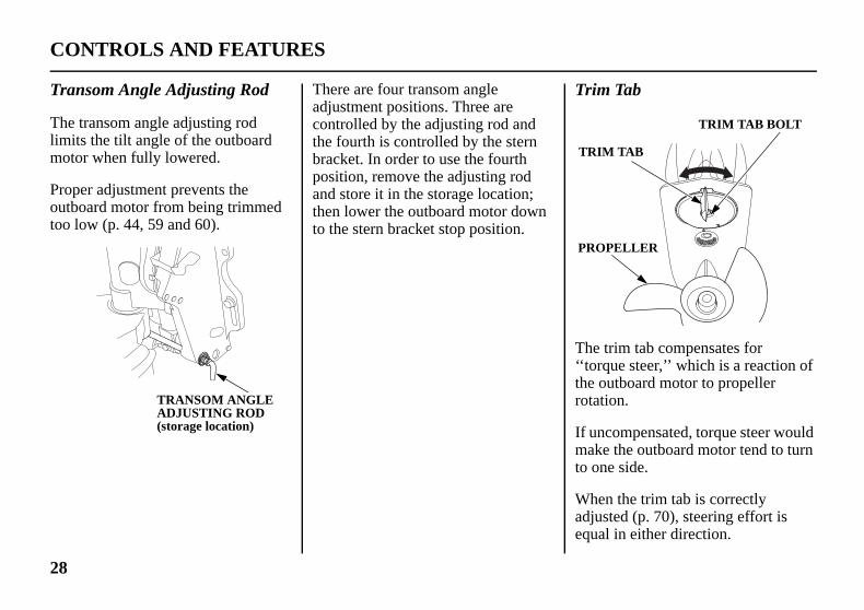
Trim Tab
The trim tab compensates for ‘‘torque steer,’’ which is a reaction of the outboard motor to propeller rotation.
If uncompensated, torque steer would make the outboard motor tend to turn to one side.
When the trim tab is correctly adjusted (p. 70), steering effort is equal in either direction.
TRIM TAB
PROPELLER
TRIM TAB BOLT
31ZW26320.book 28 ページ 2013年9月30日 月曜日 午後7時35分
28
CO
Tra
The limimoto
Propoutbtoo l
NTROLS AND FEATURES
nsom Angle Adjusting Rod
transom angle adjusting rod ts the tilt angle of the outboard r when fully lowered.
er adjustment prevents the oard motor from being trimmed ow (p. 44, 59 and 60).
There are four transom angle adjustment positions. Three are controlled by the adjusting rod and the fourth is controlled by the stern bracket. In order to use the fourth position, remove the adjusting rod and store it in the storage location; then lower the outboard motor down to the stern bracket stop position.
TRANSOM ANGLE ADJUSTING ROD (storage location)

29
NTROLS AND FEATURES
Fuel Gauge [standard equipment (Canadian types)] [optional equipment (American types)]
A fuel gauge is built into the fuel tank connector of the portable fuel tank.
FUEL GAUGE
31ZW26320.book 29 ページ 2013年9月30日 月曜日 午後7時35分
INS
Trim[statype[optLRT
The trim
Refethe pprop
CO
TRUMENTS
Meter ndard equipment (LRTC )] ional equipment (SRTA and A types)]
trim meter indicates the relative angle of the outboard motor.
r to the trim meter when using ower trim/tilt switch to achieve er boat performance.
Tachometer [standard equipment (LRTC type)] [optional equipment (other types)]
The tachometer shows engine speed in revolutions per minute.
Refer to the tachometer when using the throttle and power trim/tilt controls to achieve the best performance from the boat.
TRIM METER
TACHOMETER

When the green light is lit, oil pressure is OK.
If oil pressure becomes low, the green light will go off, and the engine protection system will limit engine speed. Refer to TAKING CARE OF UNEXPECTED PROBLEMS, on p. 104.
Remote controls are also equipped with a buzzer that sounds continuously when the green light goes off. The buzzer sound stops below an engine speed of 1,400 rpm.
Low oil pressure indicates that the engine oil level is low or that there is a problem with the engine lubrication system.
31ZW26320.book 30 ページ 2013年9月30日 月曜日 午後7時35分
30
CO
IND
Oil
SHG
NTROLS AND FEATURES
ICATORS
Pressure Indicator
and LHG Types
LRG, SRT and LRT Types [standard equipment (LRTC type)] [optional equipment (LRGA, SRTA and LRTA types)]
(GREEN)(GREEN)
BUZZER

31
NTROLS AND FEATURES
Cooling System Indicator
Water should flow from the cooling system indicator while the engine is running. This shows that water is circulating through the cooling system.
If water stops flowing while the engine is running, it indicates a cooling system problem, such as clogged water intakes, which will cause engine overheating. Refer to TAKING CARE OF UNEXPECTED PROBLEMS, on p. 105.
COOLING SYSTEM INDICATOR
31ZW26320.book 31 ページ 2013年9月30日 月曜日 午後7時35分
OveSHG
LRG[statype[optSRT
BUZ
CO
rheat Indicator and LHG Types
, SRT and LRT Types ndard equipment (LRTC )] ional equipment (LRGA, A and LRTA types)]
If the engine overheats, the red light will come on, and the engine protection system will limit engine speed. When normal engine temperature is restored, the engine speed will gradually rise to normal engine speed.
If the condition persists for another 20 seconds, the engine will shut off. Refer to TAKING CARE OF UNEXPECTED PROBLEMS, on p. 105.
Remote controls are also equipped with a buzzer that sounds when the red light comes on.
Engine overheating may be the result of clogged water intakes.
(RED)
(RED)
ZER

The anodes are made of a sacrificial material that helps to protect the outboard motor from corrosion.
There are two anodes, one on the left stern bracket, and another on the trim tab.
31ZW26320.book 32 ページ 2013年9月30日 月曜日 午後7時35分
32
CO
The discplug
NTROLS AND FEATURES
cooling system indicator harge port can also become ged.
OTHER FEATURES
Anodes
ANODE (trim tab)
ANODE LEFT STERN BRACKET

33
NTROLS AND FEATURES
Fuel Filler Cap Vent Knob
The fuel filler cap is provided with a vent knob to seal the portable fuel tank for carrying it to and from the boat. Turn the portable fuel tank vent knob counterclockwise to the open position before starting the engine.
OPEN
CLOSE
VENT KNOB
FUEL FILLER CAP
31ZW26320.book 33 ページ 2013年9月30日 月曜日 午後7時35分
Ove
The overpossfrom
The durispeeexcevent
If thchecmoto
Cheinsta
CO
rrev Limiter
engine is equipped with an rev limiter to prevent the ibility of mechanical damage excessive engine speed.
overrev limiter may be activated ng operation, limiting engine d, if the outboard motor is tilted ssively, or when propeller ilation occurs during a sharp turn.
e overrev limiter is activated, k the trim angle of the outboard r.
ck to see if the correct propeller is lled.
Portable Fuel Tank [standard equipment (Canadian types)] [optional equipment (American types)]
The portable fuel tank has a capacity of 6.6 US gal (25L) and has a fuel gauge built into the fuel tank connector.

31ZW26320.book 34 ページ 2013年9月30日 月曜日 午後7時35分
34
CO
Fue
A prhoseoutb
Befoprimarrountilthat
NTROLS AND FEATURES
l Priming Bulb
iming bulb is built into the fuel that connects the fuel tank to the oard motor.
re starting the engine, hold the ing bulb up in the direction of the
w, then squeeze the priming bulb it feels firm. This will ensure fuel is supplied to the engine.
UP
OUTLET END (outboard motor side)
FUEL PRIMING BULB
INLET END (fuel tank side)

35
INSTALLATIONThe antiventilation plate of the outboard motor should be 0 – 2 in (0 – 50 mm) below the bottom of the boat. The correct dimensions differ according to the type of boat and the configuration of the bottom of the boat. Follow the manufacturer’s recommended installation height.
TypeOutboard Motor Transom
Height (when transom angle is 12°)
S 17.0 in (431 mm)L 21.7 in (552 mm)
BOAT TRANSOM HEIGHT
0 – 2 in(0 – 50 mm)
ANTIVENTILATION PLATE
31ZW26320.book 35 ページ 2013年9月30日 月曜日 午後7時35分
Corresseperfinstr
POW
Befothat excehorsto becertimaxcertiavaiman
For motoratinmaxfor t
ect and secure installation is ntial for safe boating and good ormance. Follow the installation uctions provided in this manual.
ER REQUIREMENTS
re installation, check to be sure the outboard motor does not ed the recommended maximum epower for the boat on which it is installed. Refer to the boat’s fication plate for recommended imum horsepower. If the fication plate information is not lable, contact the boat dealer or ufacturer.
most applications, the outboard r should have a horsepower g which provides 80% of the imum recommended horsepower he boat.
BOAT TRANSOM REQUIREMENTS
Honda BF25D and BF30D outboard motors can be installed on a boat transom having a thickness range of 1.3 – 2.2 inches (35 – 57 mm).
INSTALLATION POSITION
Install the outboard motor on the center of the boat transom.
CENTER LINES
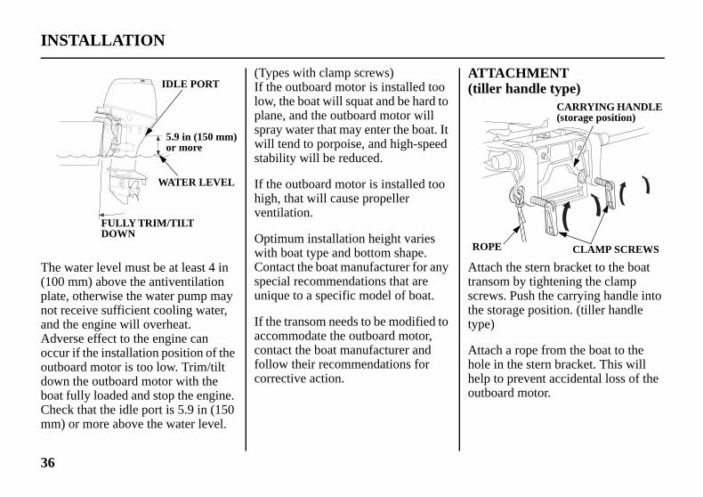
ATTACHMENT (tiller handle type)
Attach the stern bracket to the boat transom by tightening the clamp screws. Push the carrying handle into the storage position. (tiller handle type)
Attach a rope from the boat to the hole in the stern bracket. This will help to prevent accidental loss of the outboard motor.
CARRYING HANDLE (storage position)
ROPE CLAMP SCREWS
31ZW26320.book 36 ページ 2013年9月30日 月曜日 午後7時35分
36
INS
The (100platenot rand AdvoccuoutbdowboatChemm)
TALLATION
water level must be at least 4 in mm) above the antiventilation , otherwise the water pump may eceive sufficient cooling water, the engine will overheat. erse effect to the engine can r if the installation position of the oard motor is too low. Trim/tilt n the outboard motor with the fully loaded and stop the engine. ck that the idle port is 5.9 in (150 or more above the water level.
(Types with clamp screws) If the outboard motor is installed too low, the boat will squat and be hard to plane, and the outboard motor will spray water that may enter the boat. It will tend to porpoise, and high-speed stability will be reduced.
If the outboard motor is installed too high, that will cause propeller ventilation.
Optimum installation height varies with boat type and bottom shape. Contact the boat manufacturer for any special recommendations that are unique to a specific model of boat.
If the transom needs to be modified to accommodate the outboard motor, contact the boat manufacturer and follow their recommendations for corrective action.
FULLY TRIM/TILT DOWN
WATER LEVEL
5.9 in (150 mm) or more
IDLE PORT

37
INSTALLATION
31ZW26320.book 37 ページ 2013年9月30日 月曜日 午後7時35分
Youmotothe bboltsstainwashbolt
LOC
WAS
LOCNUTTRABOA
may further secure the outboard r by bolting the stern bracket to oat transom. Use the mounting and nut kit or other good quality less steel bolts, nuts, and ers. Apply silicone sealant to the holes.
TRANSOM ANGLE ADJUSTMENT
Use the transom angle adjusting rod (p. 43) to adjust the angle of the outboard motor so the propeller is perpendicular to the surface of the water.
K NUT
HERS
K
NSOM RD
MOUNTING HOLES
WASHER
MOUNTING BOLTS
WASHER

31ZW26320.book 38 ページ 2013年9月30日 月曜日 午後7時35分
38
INS
ELECO
ChaHonmotobatteequibatteis prloca
The is decranintentypeacceconn
BatThe corrsecufromwate
TALLATION
CTRICAL NNECTIONS
rging Systemda BF25D and BF30D outboard rs produce a 12-volt, 10-ampere ry-charging current and are pped for connection to a 12-volt ry. The battery-charging circuit otected by a 15-ampere fuse ted in the engine compartment.
outboard motor’s 12-volt output signed to charge a ‘‘starting or king’’ battery only. It is not ded to charge a ‘‘deep-cycle’’
battery. Lights and electrical ssories for the boat should be ected to the battery.
tery Locationbattery should be kept in a osion-resistant battery box that is rely mounted in a location away the fuel tank and protected from r and direct sunlight.

39
INSTALLATION
• Be careful to avoid connecting the battery in reverse polarity, as this will damage the battery-charging system in the outboard motor.
• Do not disconnect the battery cables while the engine is running. Disconnecting the cables while the engine is running will damage the outboard motor’s electrical system.
• Battery cable extension: Extending the original battery cable will cause the battery voltage to drop due to the increased length of the cable and number of connections. The outboard may not start if the battery voltage reaching the engine is too low.
WARNING: Battery posts, terminals, and related accessories contain lead and lead compounds. Wash your hands after handling.
31ZW26320.book 39 ページ 2013年9月30日 月曜日 午後7時35分
Bat
For batte
Min
12V(CC
tery
complete information, refer to the ry manufacturer’s instructions.
imum Requirements
-52Ah/5HR (65Ah/20HR) A 420)
Battery Connections
Connect the positive (+) battery cable to the positive (+) battery terminal, then connect the negative (–) battery cable to the negative (–) battery terminal.
The negative (–) battery cable should always be removed from the battery before connecting or disconnecting the positive (+) battery cable, so tools cannot cause a short circuit if they touch a grounded part while being used on the positive (+) battery terminal fitting.
(–) BATTERY TERMINAL(+) BATTERY TERMINAL
RED
BLACK

Before beginning your pre-operation checks, be sure the switch clip is removed or the ignition switch is in the OFF position.
Improperly maintaining this outboard motor or failing to correct a problem before operation can cause a malfunction in which you could be seriously hurt or killed.
Always perform a pre-operation inspection before each operation, and correct any problem.
31ZW26320.book 40 ページ 2013年9月30日 月曜日 午後7時35分
40
BEAREUND
Youlittlesigninjur
Kno
ReadKnoto op
Famoutbbefoto do
Famreguuse o
FORE OPERATION YOU READY TO GET ERWAY?
r safety is your responsibility. A time spent in preparation will ificantly reduce your risk of y.
wledge
and understand this manual. w what the controls do and how erate them.
iliarize yourself with the oard motor and its operation re you get underway. Know what in case of an emergency.
iliarize yourself with all laws and lations relating to boating and the f outboard motors.
Safety
Always wear a PFD (Personal Flotation Device) while on the boat.
Attach the emergency stop switch lanyard securely to the operator or to the operator’s PFD.
IS YOUR OUTBOARD MOTOR READY TO GO?
For your safety, and to maximize the service life of your equipment, it is very important to take a few moments before you operate the outboard motor to check its condition. Be sure to take care of any problem you find, or have your authorized Honda Marine dealer correct it, before you operate the outboard motor.

41
BEFORE OPERATION
• Make sure the tool kit and emergency starter rope are onboard (p. 67). Replace any missing items.
• Check the fuel level in the fuel tank (p. 79).
• Check that the battery fluid is between the upper and lower levels, and the battery leads are connected securely.
31ZW26320.book 41 ページ 2013年9月30日 月曜日 午後7時35分
Safe
• Beunoi
• If tacoth
• Chun(p
• Wth
• Chthin
• Chop
• Re
ty Inspection
fore each use, look around and derneath the engine for signs of l or gasoline leaks.
you are using the portable fuel nk, make sure it is in good ndition and properly secured in e boat (p. 45).
eck that the fuel hose is damaged and properly connected . 45).
ipe up any spills before starting e engine.
eck the stern bracket to be sure e outboard motor is securely stalled.
eck that all controls are erating properly.
place any damaged parts.
• Check that all fasteners are in place and securely tightened.
• Check the emergency stop switch for proper operation. Start the engine (p. 46, 49 or 54). Make sure the engine stops by pulling the emergency stop switch clip from the emergency stop switch.
Maintenance Inspection
• Check the engine oil level (p. 72). Running the engine with a low oil level can cause engine damage.
• Check to be sure the propeller is undamaged and the castle nut is secured with the cotter pin (p. 86).
• Check that the stern bracket anode and the trim tab are securely attached and are not excessively worn. The anodes help to protect the outboard motor from corrosion.

Next 60 minutes:Run the engine up to a maximum of 4,000 to 5,000 rpm, which is about 50% to 80% of maximum throttle opening. Operating at maximum 4,000 ~ 5,000 rpm should be limited to 50% of the 60 minutes.30-second full-throttle bursts are OK, but do not operate the engine continuously at full throttle.
For boats that plane easily, bring the boat up on plane, and then reduce the throttle opening to the recommended rpm range.
Next 8 hours:Do not run the engine at full throttle for more than 5 minutes at a time.
31ZW26320.book 42 ページ 2013年9月30日 月曜日 午後7時35分
42
OPSAFPRE
To sthis comoperprac
Befofor tIMPINFchap
For engienclconta cocollemoncons
ERATIONE OPERATING CAUTIONS
afely realize the full potential of outboard motor, you need a plete understanding of its ation and a certain amount of tice with its controls.
re operating the outboard motor he first time, please review theORTANT SAFETYORMATION on page 7 and the ter titled BEFORE OPERATION.
your safety, do not start or run the ne in a confined or partly osed area. Your engine’s exhaust ains poisonous carbon monoxide, lorless, odorless gas that can ct rapidly. Breathing carbon oxide can cause loss of ciousness and may lead to death.
BREAK-IN PROCEDURE
Break-in period: 10 hours
Proper break-in operation allows the moving parts to wear in smoothly for best performance and long service life. Avoid continuous operation at a steady speed.
First 15 minutes:Run the engine at trolling speed. Use the minimum throttle opening necessary to operate the boat at a safe trolling speed.
Next 45 minutes:Run the engine up to a maximum of 2,000 to 3,000 rpm, which is about 10% to 30% of maximum throttle opening. Operating at maximum 2,000 ~ 3,000 rpm should be limited to 50% of the 45 minutes.

43
OPERATION
Do not allow water to enter the idle exhaust port or the engine can be damaged.
IDLE EXHAUST PORT
31ZW26320.book 43 ページ 2013年9月30日 月曜日 午後7時35分
TRAADJ
UNLPOS
LOC
NSOM ANGLE USTMENT
The transom angle adjusting rod limits the tilt angle of the outboard motor when fully lowered.
Proper adjustment prevents the outboard motor from being trimmed too low (p. 59 and 60).
To adjust, first tilt the outboard motor so it is not resting on the rod.
Push the rod in and turn the end of the rod up, so the latch will fall into line with the rod.
Remove the rod and reinsert it in the desired position.
Push the rod in and turn the end of the rod down, so the latch will fall to the locked position. Then release the rod.
PUSH
TRANSOM ANGLEADJUSTING ROD
OCKEDITION
TRANSOM ANGLEADJUSTING ROD
TO CHANGE
KED POSITION TO LOCK
TURN UP

PORTABLE FUEL TANK [standard equipment (Canadian types)] [optional equipment (American types)]
Place the portable fuel tank in a well-ventilated location, away from direct sunlight, to reduce the possibility of a gasoline vapor explosion.
To ensure that the outboard motor will be able to draw fuel from the tank, place the tank within 6 feet (2 m) of the outboard motor and not more than 3 feet (1 m) below the fuel connector on the outboard motor.
PORTABLE FUEL TANK
FUEL HOSE(standard equipment)
31ZW26320.book 44 ページ 2013年9月30日 月曜日 午後7時35分
44
OP
InstatrimmaxTrim‘‘squTrim‘‘bow
OutInsp
INCCA
ERATION
ll the outboard motor at the best angle for stable cruising and imum power. angle too large: Causes boat to at.’’ angle too small: Causes boat to steer.’’
The trim angle differs according to the combination of the boat, outboard motor, and propeller, and the operating condition.
board Motor Angle ection (Cruising)
ORRECTUSES BOAT TO ‘‘SQUAT’’
INCORRECTCAUSES BOAT TO ‘‘BOW STEER’’
O.K.
CORRECTGIVES MAXIMUM PERFORMANCE
45
OPERATION
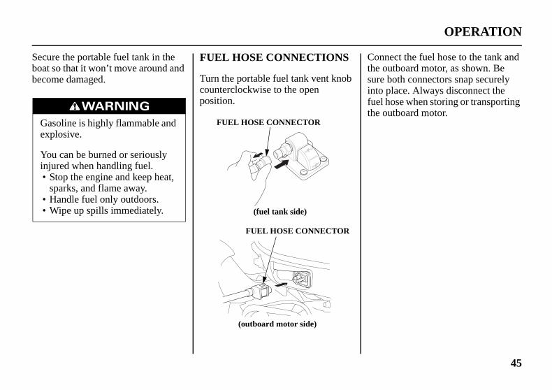
Connect the fuel hose to the tank and the outboard motor, as shown. Be sure both connectors snap securely into place. Always disconnect the fuel hose when storing or transporting the outboard motor.
31ZW26320.book 45 ページ 2013年9月30日 月曜日 午後7時35分
Secuboatbeco
Gaex
Yoin•
••
re the portable fuel tank in the so that it won’t move around and me damaged.
FUEL HOSE CONNECTIONS
Turn the portable fuel tank vent knob counterclockwise to the open position.
soline is highly flammable and plosive.
u can be burned or seriously jured when handling fuel.Stop the engine and keep heat, sparks, and flame away.Handle fuel only outdoors.Wipe up spills immediately.
FUEL HOSE CONNECTOR
(fuel tank side)
FUEL HOSE CONNECTOR
(outboard motor side)

STARTING THE ENGINE
SHG and LHG Types (long tiller handle)
1. Put the emergency stop switch clip in the emergency stop switch, and attach the emergency stop switch lanyard securely to the operator or to the operator’s PFD (Personal Flotation Device).
EMERGENCY STOP SWITCH
EMERGENCY STOPSWITCH CLIP
EMERGENCY STOPSWITCH LANYARD
31ZW26320.book 46 ページ 2013年9月30日 月曜日 午後7時35分
46
OP
FUE
If yoturncounposi
HoldoutleSquetimethat
Cheleak
Do nthe ethe ocoul
ERATION
L PRIMING
u are using a portable fuel tank, the portable fuel tank vent knob terclockwise to the open
tion.
the fuel priming bulb with the t end higher than the inlet end. eze the priming bulb several s, until it feels firm, indicating fuel has reached the carburetor.
ck to be sure there are no fuel s before starting the engine.
ot touch the priming bulb with ngine running or when tilting up utboard motor. The carburetors
d overflow.
INFREQUENT OR OCCASIONAL USE
If your outboard motor will be used on an infrequent or intermittent basis, please refer to the fuel section of the STORAGE chapter (p. 91) for additional information regarding fuel deterioration.
UPOUTLET END(outboard motor side)
FUEL PRIMINGBULB
INLET END(fuel tank side)

47
OPERATION
3. Align the engine start symbol ‘‘ ’’ on the tiller handle with the pointer ‘‘ ’’ on the throttle grip.
STARTPOSITION
POINTER
THROTTLE GRIP
ON
OFF
START
IGNITION SWITCH KEY
31ZW26320.book 47 ページ 2013年9月30日 月曜日 午後7時35分
The the ethe e
The emesystestopthe c
Alwswitoperbefo
Befooperswit
engine will not start or run unless mergency stop switch clip is in mergency stop switch.
emergency stop switch clip and rgency stop switch lanyard m is a safety device that will
the engine if you fall away from ontrols while operating the boat.
ays attach the emergency stop ch lanyard securely to the ator or to the operator’s PFD re starting the engine.
re leaving the dock, check the ation of the emergency stop ch.
2. Check the position of the gearshift lever. It must be in the N (neutral) position for starting.
The engine will not start if the gearshift lever is in the F (forward) or R (reverse) position.
N (neutral)
GEARSHIFT LEVER

During the warm-up period, check the oil pressure indicator (p. 30), overheat indicator (p. 31) and cooling system indicator (p. 31).
If the indicators show any abnormal condition, immediately stop the engine and determine the cause of the problem. Refer to TAKING CARE OF UNEXPECTED PROBLEMS on p. 104.
31ZW26320.book 48 ページ 2013年9月30日 月曜日 午後7時35分
48
OP
4. TuSTunWkepo
If seleth
• Uthovda
• Tuthensta
AthSL
ERATION
rn the ignition switch key to the ART position and hold it there til the engine starts. hen the engine starts, release the y, allowing it to return to the ON sition.
the engine fails to start within 5 conds, release the key and wait at ast 10 seconds before operating e starter again.
sing the electric starter for more an 5 seconds at a time will erheat the starter motor and can mage it.rning the ignition switch key to e START position while the gine is running can damage the rter motor and flywheel.
lso, as the engine warms up, the rottle grip can be turned to the OW position without stalling.
5. Before getting underway, allow the engine to warm-up sufficiently to ensure good performance.
Above 41°F (5°C), warm-up the engine for at least 3 minutes.
Below 41°F (5°C), warm up the engine for at least 10 minutes at approx. 2,000 rpm.
• If the engine is not properly warmed up before raising the engine speed, the buzzer and overheat indicator may activate and the engine speed will be automatically reduced.
• The cooling system may freeze in areas where the temperature reaches 32°F (0°C) or below. Cruising at high speed without warming the engine up may cause engine damage.

49
OPERATION
2. Set the control lever in the N (neutral) position.
The engine will not start if the F (forward) or R (reverse) gears are engaged.
N (neutral)
CONTROLLEVER
31ZW26320.book 49 ページ 2013年9月30日 月曜日 午後7時35分
LRG(rem
For pcontinstrcont
Side[statype[optSRT
EMESTO
EMSWI
, SRT and LRT Types ote control)
anel-mount or top-mount remote rol information, refer to the uctions provided with the remote rol equipment.
-Mount Type ndard equipment (LRTC )] ional equipment (LRGA, A and LRTA types)]
1. Put the emergency stop switch clip in the emergency stop switch, and attach the emergency stop switch lanyard securely to the operator or to the operator’s PFD (Personal Flotation Device).
The engine will not start or run unless the emergency stop switch clip is in the emergency stop switch.
The emergency stop switch clip and emergency stop switch lanyard system is a safety device that will stop the engine if you fall away from the controls while operating the boat.
Always attach the emergency stop switch lanyard securely to the operator or to the operator’s PFD before starting the engine. Before leaving the dock, check the operation of the emergency stop switch.
RGENCYP SWITCH
ERGENCY STOPTCH CLIP
EMERGENCYSTOP SWICHLANYARD

• Using the electric starter for more than 5 seconds at a time will overheat the starter motor and can damage it.
• Turning the ignition switch key to the START position while the engine is running can damage the starter motor and flywheel.
5. Before getting underway, allow the engine to warm-up sufficiently to ensure good performance.
Above 41°F (5°C), warm-up the engine for at least 3 minutes.
Below 41°F (5°C), warm up the engine for at least 10 minutes at approx. 2,000 rpm.
31ZW26320.book 50 ページ 2013年9月30日 月曜日 午後7時35分
50
OP
3. Toidlo
Tofa
Thun(n
Thawun
ERATION
start a cold engine, leave the fast le lever in the START (fully wered) position.
restart a warm engine, raise the st idle lever.
e fast idle lever cannot be raised less the control lever is in the N eutral) position.
e control lever cannot be moved ay from the N (neutral) position less the fast idle lever is lowered.
4. Turn the ignition switch key to the START position and hold it there until the engine starts. When the engine starts, release the key, allowing it to return to the ON position.
If the engine fails to start within 5 seconds, release the key and wait at least 10 seconds before operating the starter again.
FAST IDLE
START
FAST IDLE LEVER
OFFON START
IGNITION SWITCH KEY

51
OPERATION
EMERGENCY STARTING
If the battery is discharged or the starter motor is inoperative, you can start the engine manually using the emergency starter rope that came with your outboard motor.
1. Unlatch the engine cover latch and remove the engine cover.
(REAR)
ENGINE COVERLATCH
UNLATCH
31ZW26320.book 51 ページ 2013年9月30日 月曜日 午後7時35分
• If waenovanau
• TharreCrwaen
Dthovco
If abstocaTAUp.
the engine is not properly rmed up before raising the gine speed, the buzzer and erheat indicator may activate d the engine speed will be tomatically reduced.e cooling system may freeze in eas where the temperature aches 32°F (0°C) or below. uising at high speed without rming the engine up may cause gine damage.
uring the warm-up period, check e oil pressure indicator (p. 30), erheat indicator (p. 31), and oling system indicator (p. 31).
the indicators show any normal condition, immediately p the engine and determine the
use of the problem. Refer to KING CARE OF
NEXPECTED PROBLEMS on 104.
6. If the fast idle lever was used to start the engine, gradually lower the lever as the engine warms up.
When the fast idle lever is fully lowered, the control lever can be moved away from the N (neutral) position.
FAST IDLE LEVER

4. Set the knot at the end of the emergency starter rope in the notch in the flywheel. Wind the rope clockwise around the flywheel, as shown.
KNOT
FLYWHEEL
EMERGENCYSTARTERROPE
31ZW26320.book 52 ページ 2013年9月30日 月曜日 午後7時35分
52
OP
2. Reunbo
6
ERATION
move the flywheel cover by screwing the four 6 × 22 mm lts.
3. Set the controls the same as for normal starting (see pages 46 – 51). Use the fast idle control if needed.
Turn the ignition switch key to the ON position.
× 22 mm BOLTS
FLYWHEEL COVER

53
OPERATION
8. If it was necessary to remove the emergency stop switch lanyard from you to perform the emergency starting procedure, be sure the lanyard is attached securely to operator before operating the outboard motor.
9. Have your closest authorized Honda Marine dealer check your electrical system and correct the problem so that you can use the electric starter.
31ZW26320.book 53 ページ 2013年9月30日 月曜日 午後7時35分
5. Puslopu
Kw
If pustaTAUfro
ll the emergency starter rope wly until resistance is felt, then ll briskly.
eep away from moving parts hile pulling the rope.
necessary, rewind the rope and ll again. If the engine does not rt after several attempts, refer to KING CARE OF
NEXPECTED PROBLEMS m p. 98.
6. If the fast idle control(s) was used to start the engine, return the control(s) to the normal operating position as the engine warms up.
During the warm-up period, check the oil pressure indicator (p. 30), overheat indicator (p. 31), and cooling system indicator (p. 31).
7. Leave the flywheel cover off, but install the engine cover (p. 71) and lock it in place by latching the engine cover latch.
EMERGENCYSTARTER ROPE
Direction to pull
Exposed moving parts can cause injury.
• Do not operate the outboard motor without the engine cover.
• Use extreme care when installing the engine cover.

Normal Engine Stopping
SHG and LHG Types (long tiller handle)
SLOW
THROTTLE GRIP
N (neutral)
GEARSHIFT LEVER
31ZW26320.book 54 ページ 2013年9月30日 月曜日 午後7時35分
54
OP
STO
Em
SHG(lon
LRG(rem
EMESWI
E
EMESTO
EM
ERATION
PPING THE ENGINE
ergency Engine Stopping
and LHG Types g tiller handle)
, SRT and LRT Types ote control)
To stop the engine in an emergency, pull the emergency stop switch clip out of the emergency stop switch by pulling the emergency stop switch lanyard.We suggest that you stop the engine this way occasionally to verify that the emergency stop switch is operating properly.
Before leaving the dock, check the operation of the emergency stop switch.
Turn the ignition switch key to the OFF position after verifying the emergency stop switch operation.
EMERGENCYSTOP SWITCH
RGENCY STOPCH LANYARDMERGENCY STOP SWITCH CLIP
PULL
RGENCYP SWITCH
EMERGENCYSTOP SWICHLANYARD
PULL
ERGENCY STOP SWITCH CLIP

55
OPERATION
2. Turn the ignition switch key to the OFF position to stop the engine. In the event that the engine does not stop when the ignition switch key is turned to the OFF position, pull the emergency stop switch clip out of the emergency stop switch by pulling the emergency stop switch lanyard (p. 54).
3. When the boat is not in use, remove and store the ignition switch key and the emergency stop switch clip and lanyard. If you are using a portable fuel tank, disconnect the fuel hose if you will be storing or transporting the outboard motor.
31ZW26320.book 55 ページ 2013年9月30日 月曜日 午後7時35分
LRG[remtype
1. Mslole(n
Adomen
COLEV
, SRT and LRT Types ote control (side-mount
)]
ove the throttle grip to the west speed and the gearshift
ver or control lever to the N eutral) position.
fter cruising at full throttle, cool wn the engine by idling for a few inutes before stopping the gine.
SHG and LHG Types (long tiller handle)
LRG, SRT and LRT Types (remote control)
N (neutral)
NTROLER
OFF
IGNITION SWITCH KEY
IGNITIONSWITCH KEY
OFF

Use the throttle friction adjuster to help hold a constant throttle setting while cruising.
Turn the adjuster clockwise to increase throttle grip friction for holding a constant speed.
Turn the adjuster counterclockwise to decrease friction for easy grip rotation.
THROTTLE FRICTION ADJUSTER
RELEASE
FIX
THROTTLEGRIP
31ZW26320.book 56 ページ 2013年9月30日 月曜日 午後7時35分
56
OP
GEATHR
SHG(lon
F(f
ERATION
RSHIFT AND OTTLE OPERATION
and LHG Types g tiller handle)
To shift gears, turn the throttle grip to the SLOW position; then move the gearshift lever to select the F (forward), N (neutral), or R (reverse) gears.
The engine can be started with the gearshift lever in the N (neutral) position only.
The throttle grip can be turned to the FAST position only when the gearshift lever is in the F (forward) position.
POINTERTHROTTLEGRIP
SLOW
FAST
N(neutral)
R(reverse)
orward)
GEARSHIFTLEVER

57
OPERATION
Adjust the control lever friction adjuster so the control lever will hold a constant throttle setting while cruising.
TO INCREASEFRICTION
TO DECREASEFRICTION
CONTROL LEVERFRICTION ADJUSTER
31ZW26320.book 57 ページ 2013年9月30日 月曜日 午後7時35分
LRG[remtype
CO
, SRT and LRT Types ote control (side-mount
)]
To shift gears, move the control lever to select the F (forward), N (neutral), or R (reverse) gear.
The control lever cannot be moved from the N (neutral) position unless the neutral release lever is squeezed.
Moving the control lever beyond the gear selection range increases engine speed.
NTROL LEVER
NEUTRALRELEASE LEVER

Use the steering friction adjuster to help hold a steady course while cruising.
Move the adjuster to the LOCK direction to increase steering friction for holding a steady course.
Move the adjuster to the FREE direction to decrease friction for easy turning.
Do not apply grease or oil on the friction plate. Grease or oil will reduce the friction of the adjuster.
LRG, SRT and LRT Types (remote control)
Steer the boat in the same manner as an automobile.
31ZW26320.book 58 ページ 2013年9月30日 月曜日 午後7時35分
58
OP
STE
SHG(lon
Steeoppoboat
R
Moha
ERATION
ERING
and LHG Types g tiller handle)
r by moving the tiller handle site the direction you want the
to turn.
Steering Friction Adjuster
IGHT TURN LEFT TURN
ve the tillerndle to the left.
Move the tillerhandle to the right.
STEERING FRICTION ADJUSTER
FRICTIONPLATE
TO INCREASEFRICTION(LOCK)
TO DECREASEFRICTION(FREE)

59
OPERATION
antiventilation plate is level with the water surface.
When cruising into a high wind, trim the outboard motor down slightly to level the boat and improve stability. With a tail wind, trim the outboard motor up slightly.
SRT and LRT Types
Use the power trim/tilt switch to trim the outboard motor for the best performance and stability.
You can use the power trim/tilt switch at any time, whether the boat is underway or stopped.
Press the UP or DN (down) side of the switch to adjust the angle of the outboard motor.
Refer to the trim meter (p. 29) for an indication of whether the outboard motor is trimmed high or low.
31ZW26320.book 59 ページ 2013年9月30日 月曜日 午後7時35分
CRU
Eng
For throthroto he
For wavprop
The overpossfrom
If, fotiltedventthe ethe o
ISING
ine Speed
best fuel economy, limit the ttle opening to 80%. Use the ttle friction control (p. 56 and 57) lp you hold a steady speed.
rough water conditions or large es, slow down to prevent the eller from rising out of the water.
engine is equipped with an rev limiter to prevent the ibility of mechanical damage excessive engine speed.
r example, the outboard motor is excessively or propeller
ilation occurs during a sharp turn, ngine may overrev, activating verrev limiter.
If engine speed becomes unstable at high speed due to activation of the overrev limiter, reduce speed and check the trim angle of the outboard motor.
Trim
SHG, LRG and LHG Types
Install the outboard motor at the best trim angle for stable cruising and maximum power.
Trim angle too large: Causes boat to ‘‘squat.’’
Trim angle too small: Causes boat to ‘‘bow steer.’’
It is necessary to trim the angle of the outboard motor to compensate for changes in boat load, weight distribution, water conditions, or propeller selection.
Under normal conditions, the boat will perform best when the

OUTBOARDMOTORTRIMMEDTOO LOW
OUTBOARDMOTORTRIMMEDTOO HIGH
OUTBOARDMOTORTRIMMEDCORRECTLY
ROUGHWAVES
CORRECT TRIM/TILT ANGLEGIVES MAXIMUM PERFORMANCE
31ZW26320.book 60 ページ 2013年9月30日 月曜日 午後7時35分
60
OP
It is outbchandistrprop
Undwill antivwate
Wheadjuslighstaboutb
Exceoperventpumnot cLim
ERATION
necessary to trim the angle of the oard motor to compensate for ges in boat load, weight ibution, water conditions, or eller selection.
er normal conditions, the boat perform best when the entilation plate is level with the r surface.
n cruising into a high wind, st the outboard motor down tly to level the boat and improve
ility. With a tail wind, adjust the oard motor up slightly.
ssive trim/tilt angle during ation can cause propeller ilation, overheating, and water p damage. This type of damage is overed by the Distributor’s
ited Warranty (p. 121).
SRT and LRT TypesPOWER TRIM/TILT SWITCH
Press UP to trim ortilt the outboardmotor up.
Press DN to trim ortilt the outboardmotor down.
CONTROL LEVER

61
OPERATION
SHALLOW WATER OPERATION
SRT and LRT Types
When operating in shallow water, use the power trim/tilt switch (p. 60) to tilt the outboard motor so that the propeller and gear case won’t hit the bottom.
Proceed at low speed, and monitor water flow from the cooling system indicator (p. 31) to be sure the outboard motor is not tilted so high that the water intakes are out of the water.
An excessive trim/tilt angle during operation can cause propeller ventilation, overheating, and water pump damage. This type of damage is not covered by the Distributor’s Limited Warranty (p. 121).
31ZW26320.book 61 ページ 2013年9月30日 月曜日 午後7時35分
BOW1. LO2. OU
TO
BOW1. LO2. OU
TO
TOO LOW DUE TOAD IN THE FRONTTBOARD MOTOR TRIMMED O LOW
TOO HIGH DUE TOAD IN THE REARTBOARD MOTOR TRIMMED O HIGH
TRIM TAB
If steering effort is not equal in both directions, adjust the trim tab to compensate for ‘‘torque steer,’’ which is the reaction of the outboard motor to propeller rotation.
Adjust the trim tab (p. 70) with the engine stopped. Loosen the trim tab bolt above the trim tab, turn the trim tab, and then tighten the bolt securely.
When the trim tab is correctly adjusted, steering effort will be equal in both directions.
TRIM TAB BOLT
TRIM TAB
PROPELLER

While the outboard motor is tilted, proceed at a low speed, and do not operate the outboard motor in reverse. The outboard motor will rise suddenly if operated in reverse.
Monitor water flow from the cooling system indicator (p. 31) to be sure the outboard motor is not tilted so high that the water intake is out of the water.
An excessive tilt angle during operation can cause propeller ventilation, overheating, and water pump damage. This type of damage is not covered by the Distributor’sLimited Warranty (p. 121).
To return the outboard motor to the normal operating position, move the tilt lever to the LOCK (RUN) position. You may need to raise the outboard motor slightly to disengage the tilt mechanism, and then slowly lower the outboard motor.
31ZW26320.book 62 ページ 2013年9月30日 月曜日 午後7時35分
62
OP
SHG
Whethe olevewon
ERATION
, LRG and LHG Types
n operating in shallow water, tilt utboard motor, using the tilt
r, so the propeller and gear case ’t hit the bottom.
To tilt the outboard motor, move the tilt lever to the TILT position, then raise the outboard motor to the desired position by pulling on the engine cover grip.
Do not use the tiller handle as a lever to raise the outboard motor. Applying excessive force to the tiller handle can damage it.
64°
12°
0°
– 4°
TILT ANGLE12°
TRIM ANGLE0°(VERTICAL LINE)
(transom angle at 12°)
ENGINE COVER GRIP
TILT
RUN(LOCK)
TILT LEVER

63
OPERATION
Do not attempt to use the power tilt switch to tilt the outboard motor down while the tilt lock lever is in the LOCK position. Damage to the power tilt system may occur.
LOCKFREE
STERNBRACKET
TILT LOCK LEVER(lock position)
31ZW26320.book 63 ページ 2013年9月30日 月曜日 午後7時35分
MOLAU
Befomotominudrainengi
Stopfuel befo
SHGUse the op. 62
SRTTo rawatethe bclealaunon thmototilt lthen
ORING, BEACHING, NCHING
re tilting up, leave the outboard r in the running position for one te after stopping the engine to the water from inside the
ne.
the engine and disconnect the hose from the outboard motor re tilting the outboard motor.
, LRG and LHG Typesthe tilt lever to raise and lower utboard motor as described on .
and LRT Typesise the outboard motor out of the r while the engine is stopped and oat is moored, or for maximum
rance when beaching or ching, use the power tilt switch e engine pan to tilt the outboard r up as far as it will go, move the
ock lever to the LOCK position, gently lower the outboard motor
until the lever contacts the stern bracket.
If more clearance is needed to swing the tilt lock lever into the LOCK position, rock the outboard motor forward slightly by pulling on the engine cover grip.
To lower the outboard motor, tilt up, move the tilt lock lever to the FREE position, and then lower the outboard motor to the desired position.
POWER TILT SWITCH(SRT and LRT types)

31ZW26320.book 64 ページ 2013年9月30日 月曜日 午後7時35分
64
OP
MASRT
The manrelieoutbbatte
For screcounClosposi
RIG
ERATION
NUAL RELIEF VALVE and LRT Types
outboard motor can also be tilted ually after opening the manual f valve. This feature enables the oard motor to be tilted when no ry is connected.
manual tilting, use a flat blade wdriver to turn the valve terclockwise 2 and a half turns. e the valve firmly after tioning the engine.
Be sure the valve is closed before operating the outboard motor. If the valve is not closed, the outboard motor will tilt up when operated in reverse.
Check that nobody is under the outboard motor before opening the manual relief valve. If the manual relief valve is loosened (turned counterclockwise) when the outboard motor is tilted up, the outboard motor will suddenly tilt down.
MANUAL RELIEF VALVE
POWER (To fix)
MANUAL(To release)
HT STERN BRACKET

65
OUTBOARD MOTORRemember that your authorized Honda Marine dealer knows your outboard motor best and is fully equipped to maintain and repair it.
To ensure the best quality and reliability, use only new, Honda Genuine parts or their equivalents for repair and replacement.
Maintenance, replacement, or repair of the emission control devices and systems may be performed by any marine engine repair establishment or individual, using parts that are ‘‘certified’’ to EPA standards.
31ZW26320.book 65 ページ 2013年9月30日 月曜日 午後7時35分
THEMA
Propsafeoperpollu
Imoucoopmbe
AlmaanM
SERVICING YOUR IMPORTANCE OF
INTENANCE
er maintenance is essential for , economical, and trouble-free ation. It will also help reduce air tion.
To help you properly care for your outboard motor, the following pages include a maintenance schedule, routine inspection procedures, and simple maintenance procedures using basic hand tools. Other service tasks that are more difficult or require special tools are best handled by professionals and are normally performed by a Honda technician or other qualified mechanic.
The maintenance schedule applies to normal operating conditions. If you operate your outboard motor under unusual conditions, consult an authorized Honda Marine dealer for recommendations applicable to your individual needs and use.
properly maintaining this tboard motor or failure to rrect a problem before eration can cause a alfunction in which you could seriously hurt or killed.
ways follow the inspection and intenance recommendations
d schedules in this Owner’s anual.
• Read the instructions before you begin, and make sure you have the tools and skills required.
• To reduce the possibility of fire or explosion, be careful when working around gasoline. Use only a nonflammable solvent, not gasoline, to clean parts. Keep cigarettes, sparks, and flames away from all fuel-related parts.
• Wear gloves when handling the propeller to protect your hands from sharp edges.
31ZW26320.book 66 ページ 2013年9月30日 月曜日 午後7時35分
66
SER
MA
Sompreccannhazamainwhegive
Famaprse
AlanM
VICING YOUR OUTBOARD MOTOR
INTENANCE SAFETY
e of the most important safety autions follow. However, we ot warn you of every conceivable rd that can arise in performing tenance. Only you can decide
ther or not you should perform a n task.
Safety Precautions
• Make sure the engine is off before you begin any maintenance or repairs. This will eliminate several potential hazards:
─ Carbon monoxide poisoning from engine exhaust. Do not start or run the engine in a confined or partly enclosed area.
─ Burns from hot parts. Let the engine and exhaust system cool before touching.
─ Injury from moving parts. Do not run the engine unless instructed to do so.
ilure to properly follow intenance instructions and
ecautions can cause you to be riously hurt or killed.
ways follow the procedures d precautions in the Owner’s anual.

67
UR OUTBOARD MOTOR
ove can be purchased from an y be used for simple maintenance eep this tool kit or an equivalent ilable if you need them.
ot available as a kit and each item
OCKET WRENCH
TOOL BAG
31ZW26320.book 67 ページ 2013年9月30日 月曜日 午後7時35分
SPAtilleEMRO
Alwand onbostoreaccewith
SERVICING YO
RE SWITCH CLIP (long r handle type) AND ERGENCY STARTER PE
ays carry the spare switch clip the emergency starter rope ard. The spare clip may either be d in the tool bag or in an easily ssible location on the boat along the emergency starter rope.
SPARE SWITCH CLIP(long tiller handle type)
EMERGENCY STARTER ROPE
TOOL KIT
Individual items in the tool kit shown abauthorized Honda Marine dealer and maprocedures and/or emergency repairs. Konboard, so that they will always be ava
If your tool kit needs replacement, it is nmust be ordered individually.
8 × 10 mm WRENCH
FLAT SCREWDRIVER
GRIP
18 × 19 mm S

r accordingly. Please note, a claim for r your outboard motor was not r improperly performed maintenance,
d are mechanically proficient. Refer to the
tervals.
Every 6 monthsor
100 hrs.
Every yearor
200 hrs.
Every 2 yearsor
400 hrs.
oo (2)
o (2)o (2)
o (2)o (2)
o (2)o
oo (2)
o (1)
31ZW26320.book 68 ページ 2013年9月30日 月曜日 午後7時35分
68
SER
MA
Follwarrfollowou
(1)(2)
(3)
Eng
GeaEngTimCarbIdle ValvSparPropFuelTherLubAno
ITE
VICING YOUR OUTBOARD MOTOR
INTENANCE SCHEDULE
ow the MAINTENANCE SCHEDULE table and service your outboard motoanty coverage will not be denied simply because the maintenance schedule fowed. However, any part(s) that fails specifically due to lack of maintenance, old not be covered under the Distributor’s Limited Warranty.
Lubricate more frequently when used in salt water. These items should be serviced by your servicing dealer, unless you have the proper tools an
Honda shop manual for service procedures. For professional commercial use, log hours of operation to determine proper maintenance in
Each use After useFirst month
or20 hrs.
ine oil Check level oChange o
r case oil Change o (2)ine oil filter Replaceing belt Check-adjusturetor linkage Check-adjust o (2)speed Check-adjust o (2)e clearance Check-adjustk plug Check-adjust/Replaceeller and cotter pin Check o tank and tank filter Cleanmostat Check
rication Grease o (1)de metal Check outside engine o
REGULAR SERVICE PERIOD (3) Perform at every indicated month or operating hour interval, whichever comes first.
M
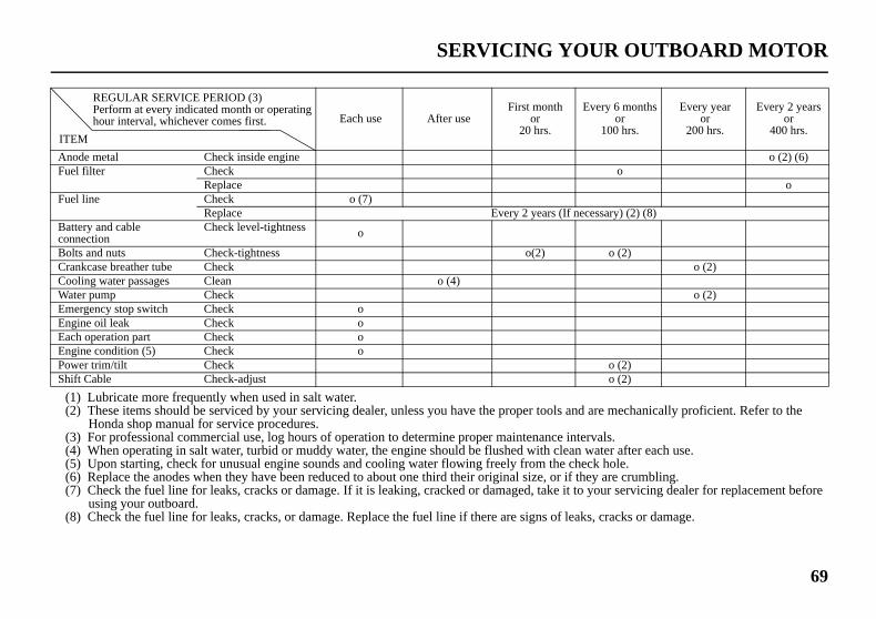
69
UR OUTBOARD MOTOR
d are mechanically proficient. Refer to the
tervals. water after each use.eck hole.
they are crumbling.o your servicing dealer for replacement before
ks, cracks or damage.
Every 6 monthsor
100 hrs.
Every yearor
200 hrs.
Every 2 yearsor
400 hrs.
o (2) (6)o
o
ecessary) (2) (8)
o (2)o (2)
o (2)
o (2)o (2)
31ZW26320.book 69 ページ 2013年9月30日 月曜日 午後7時35分
(1)(2)
(3)(4)(5)(6)(7)
(8)
AnoFuel
Fuel
BattconnBoltCranCooWatEmeEngEachEngPowShif
ITE
SERVICING YO
Lubricate more frequently when used in salt water. These items should be serviced by your servicing dealer, unless you have the proper tools an
Honda shop manual for service procedures. For professional commercial use, log hours of operation to determine proper maintenance in When operating in salt water, turbid or muddy water, the engine should be flushed with clean Upon starting, check for unusual engine sounds and cooling water flowing freely from the ch Replace the anodes when they have been reduced to about one third their original size, or if Check the fuel line for leaks, cracks or damage. If it is leaking, cracked or damaged, take it t
using your outboard. Check the fuel line for leaks, cracks, or damage. Replace the fuel line if there are signs of lea
Each use After useFirst month
or20 hrs.
de metal Check inside engine filter Check
Replace line Check o (7)
Replace Every 2 years (If nery and cableection
Check level-tightness o
s and nuts Check-tightness o(2)kcase breather tube Check
ling water passages Clean o (4)er pump Checkrgency stop switch Check oine oil leak Check o operation part Check o
ine condition (5) Check oer trim/tilt Checkt Cable Check-adjust
REGULAR SERVICE PERIOD (3) Perform at every indicated month or operating hour interval, whichever comes first.
M

If less effort is required to make right turns, move the back of the trim tab right.
Adjust the trim tab in small increments, and retest steering effort with the boat evenly loaded and running at cruising speed.
RIGHT
TRIM TAB BOLT TRIM TAB
31ZW26320.book 70 ページ 2013年9月30日 月曜日 午後7時35分
70
SER
TRI
The steeroutb
If unmakto on
Wheadjueithe
If stethe tof thbolt
VICING YOUR OUTBOARD MOTOR
M TAB ADJUSTMENT
trim tab compensates for ‘‘torque ,’’ which is a reaction of the oard motor to propeller rotation.
compensated, torque steer would e the outboard motor tend to turn e side.
n the trim tab is correctly sted, steering effort is equal in r direction.
ering effort is unequal, loosen rim tab bolt and adjust the angle e trim tab. Retighten the trim tab securely. If less effort is required to make left
turns, move the back of the trim tab left.
LEFT
TRIM TAB TRIM TAB BOLT
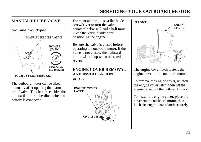
71
UR OUTBOARD MOTOR
The engine cover latch fastens the engine cover to the outboard motor.
To remove the engine cover, unlatch the engine cover latch, then lift the engine cover off the outboard motor.
To install the engine cover, place the cover on the outboard motor, then latch the engine cover latch securely.
(FRONT)ENGINECOVER
31ZW26320.book 71 ページ 2013年9月30日 月曜日 午後7時35分
MA
SRT
The manrelieoutbbatte
RI
SERVICING YO
NUAL RELIEF VALVE
and LRT Types
outboard motor can be tilted ually after opening the manual f valve. This feature enables the oard motor to be tilted when no ry is connected.
For manual tilting, use a flat blade screwdriver to turn the valve counterclockwise 2 and a half turns. Close the valve firmly after positioning the engine.
Be sure the valve is closed before operating the outboard motor. If the valve is not closed, the outboard motor will tilt up when operated in reverse.
ENGINE COVER REMOVAL AND INSTALLATION
MANUAL RELIEF VALVE
GHT STERN BRACKET
POWER (To fix)
MANUAL(To release)
(REAR)
ENGINE COVERLATCH
UNLATCHFIX

Running the engine with a low oil level can cause engine damage.
5. Install the oil filler cap and tighten it securely.
6. Install and lock the engine cover.
31ZW26320.book 72 ページ 2013年9月30日 月曜日 午後7時35分
72
SER
Eng
Cheengimoto
1. Uco
2. Rew
3. Inthle
OI
VICING YOUR OUTBOARD MOTOR
ine Oil Level Check
ck the engine oil level with the ne stopped and the outboard r in the vertical position.
nlatch and remove the engine ver (p. 71).
move the oil level dipstick and ipe it clean.
sert the dipstick all the way in, en remove it and check the oil vel shown on the dipstick.
4. If the oil level is low, remove the oil filler cap, and add oil to reach the upper limit mark shown on the dipstick. Use the oil recommended on p. 75.
L LEVEL DIPSTICK
UPPERLIMIT
LOWERLIMIT
OIL FILLER CAP

73
UR OUTBOARD MOTOR
Engine Oil Change
An engine oil evacuation device may be used to remove the engine oil.
Drain the used oil while the engine is warm. Warm oil drains quickly and completely.
1. Unlatch and remove the engine cover (p. 71). Remove the oil filler cap (p. 72).
31ZW26320.book 73 ページ 2013年9月30日 月曜日 午後7時35分
Wheappechancond
Ru3,030%eng
Frestothe
quent starting and pping without allowing engine to warm up.
• Unburned fuel mixes with the oil, increasing the volume of oil.
SERVICING YO
n you check the oil level with the dipstick, you might notice the engine oil ars milky or the oil level has increased. If you notice either condition, ge the engine oil. See the following table for an explanation of these itions.
Operating Method Result Effect
nning the engine below 00 rpm for more than
of the time so the ine does not warm up.
• Water condenses in the engine and mixes with the oil, resulting in a milky appearance.
The engine oil deteriorates, becomes less efficient as a lubricant, and causes an engine malfunction.

31ZW26320.book 74 ページ 2013年9月30日 月曜日 午後7時35分
74
SER
2. Pldrandr
3. Acosedr
DRH
VICING YOUR OUTBOARD MOTOR
ace a suitable container below the ain bolt hole to catch the used oil, d then remove the engine oil ain bolt, and sealing washer.
llow the used oil to drain mpletely, then install a new aling washer on the engine oil ain bolt, and tighten it securely.
Improper disposal of engine oil can be harmful to the environment. If you change your own oil, please dispose of the used oil properly. Put it in a sealed container, and take it to a recycling center. Do not throw it in the trash, pour it on the ground or down a drain.
AIN BOLTOLE
SEALING WASHER
ENGINE OILDRAIN BOLT

75
UR OUTBOARD MOTOR
Honda recommends that you use API service category SG, SH or SJ oil. The SAE oil viscosity and service category are in the API label on the oil container.
31ZW26320.book 75 ページ 2013年9月30日 月曜日 午後7時35分
4. Wvelim(p
EnW1.W1.
5. Init
6. In
SERVICING YO
ith the outboard motor in a rtical position, fill to the upper it mark on the oil level dipstick
. 72) with the recommended oil.
gine oil refill capacity:ithout oil filter change:7 US qt (1.6 L)ith oil filter change:8 US qt (1.7 L)
stall the oil filler cap and tighten securely.
stall and lock the engine cover.
Engine Oil Recommendations
Oil is a major factor affecting performance and service life. Use 4-stroke detergent oil.
SAE 5W-30 is recommended for general use.
AMBIENT TEMPERATURE

TILLER HANDLE(SHG and LHG types)
CLAMP SCREWS(SHG and LHG types)
SWIVEL CASE
gine cover and any exposed metal
31ZW26320.book 76 ページ 2013年9月30日 月曜日 午後7時35分
76
SER
LubAppgrea
LubAftethen(refeon p
To panticwhe
Appsurfa
VICING YOUR OUTBOARD MOTOR
rication Pointsly Honda Marine waterproof se to the parts shown below:
rication interval:r the first 20 hours or 1 month, every 100 hours or 6 months r to the maintenance schedule age 68).
revent corrosion, apply orrosion oil to pivot surfaces
re grease cannot penetrate.
TILT SHAFT
MOUNT FRAME
PROPELLER SHAFT
ly Honda Marine Corrosion Inhibitor (or equivalent) to all areas under the ences except the belts.

77
UR OUTBOARD MOTOR
5. Measure the spark plug electrode gap with a wire-type feeler gauge. Correct the gap, if necessary, by carefully bending the side electrode.
The gap should be: 0.024 – 0.028 in (0.6 – 0.7 mm)
SIDE ELECTRODE
0.024 – 0.028 in(0.6 – 0.7 mm)
SEALING WASHER
INSULATOR
31ZW26320.book 77 ページ 2013年9月30日 月曜日 午後7時35分
Spa
RECPLUDR7X22
Incoengi
1. Uco
2. Dfro
3. Resp
SPACAP
SERVICING YO
rk Plug Service
OMMENDED SPARK GS: EA (NGK) ESR-U (DENSO)
rrect spark plugs can cause ne damage.
nlatch and remove the engine ver (p. 71).isconnect the spark plug caps m the spark plugs.move the spark plugs with a ark plug wrench.
4. Inspect the spark plugs. Replace them if the electrodes are worn, or if the insulators are cracked or chipped.
RK PLUGS
SPARK PLUGWRENCH
New plug Plug needingreplacement

31ZW26320.book 78 ページ 2013年9月30日 月曜日 午後7時35分
78
SER
6. Inha
SPAPLU
VICING YOUR OUTBOARD MOTOR
stall the spark plugs carefully, by nd, to avoid cross-threading.
7. After each spark plug seats, tighten with a spark plug wrench to compress the sealing washer.
If reinstalling used spark plugs, tighten 1/8 – 1/4 turn after the spark plugs seat.
If installing new spark plugs, tighten 1/2 turn after the spark plugs seat.
Loose spark plugs can overheat and damage the engine. Overtightening the spark plugs can damage the threads in the cylinder head.
8. Attach the spark plug caps.
9. Install and lock the engine cover.
RKG

79
UR OUTBOARD MOTOR
3. Press down the pressure relief tab, and then turn the fuel filler cap 1/4 counterclockwise. Release the pressure relief tab. Wait to relieve pressure.
4. The fuel filler cap will lock again. Press down the pressure relief tab, and turn counterclockwise to remove the fuel filler cap.
FUEL FILLER CAP
PRESS
PRESSURE RELIEF TAB
31ZW26320.book 79 ページ 2013年9月30日 月曜日 午後7時35分
REF
If yothrofuel recoFuel
Por[sta(Ca[opttype
FUE6.6 U
Chetank
Remfor r
SERVICING YO
UELING
u do not anticipate cycling ugh at least one complete tank of within a 30 day period, we mmend adding Honda Marine Stabilizer each time you refuel.
table Fuel Tank ndard equipment nadian types)] ional equipment (American s)]
L TANK CAPACITY: S gal (25 L)
ck the fuel gauge and refill the when necessary.
ove the fuel tank from the boat efueling.
1. Turn the vent knob counterclockwise to the OPEN position.
2. Turn the fuel filler cap counterclockwise so that it touches the pressure relief tab.
FUEL GAUGE
VENT KNOB
OPEN
FUEL FILLER CAP
PRESSURE RELIEF TAB

Never refill the fuel tank inside a building where gasoline fumes may reach flames or sparks. Keep gasoline away from appliance pilot lights, barbecues, electric appliances, power tools, etc.
Spilled fuel is not only a fire hazard, it causes environmental damage. Wipe up spills immediately.
Gasoline is highly flammable and explosive.
You can be burned or seriously injured when handling fuel.• Stop the engine and keep heat,
sparks, and flame away.• Handle fuel only outdoors.• Wipe up spills immediately.
31ZW26320.book 80 ページ 2013年9月30日 月曜日 午後7時35分
80
SER
Refuthe tline.
Aftetightthe vCLOtank
SAF
FUE
VICING YOUR OUTBOARD MOTOR
el in a well-ventilated area. Fill ank to the SAFE FILL LEVEL
r refueling, install the cap and en it until you hear it click. Turn ent knob clockwise to the SED position, and return the fuel
to the boat.
Using the fuel tank mounted in the boat.
Check the fuel level and refill if necessary. Do not fill the fuel tank above the UPPER LIMIT. Refer to the boat manufacturer’s instructions.
Fuel can damage paint and plastic. Be careful not to spill fuel when filling your fuel tank. Damage caused by spilled fuel is not covered under warranty.
E FILL LEVEL
L FILLER CAPVENT KNOB
CLOSE

81
UR OUTBOARD MOTOR
31ZW26320.book 81 ページ 2013年9月30日 月曜日 午後7時35分
FUE
Thisunleocta
Youcont(E10addicosoUse or mabovperfdampartsEngprobwithmethare n
NevgasoAvotank
SERVICING YO
L RECOMMENDATIONS
engine is certified to operate on aded gasoline with a pump ne rating of 86 or higher.
may use unleaded gasoline aining no more than 10% ethanol ) or 5% methanol by volume. In tion, methanol must contain lvents and corrosion inhibitors. of fuels with content of ethanol ethanol greater than shown e may cause starting and/or
ormance problems. It may also age metal, rubber, and plastic of the fuel system.
ine damage or performance lems that result from using a fuel percentages of ethanol or anol greater than shown above ot covered under warranty.
er use stale or contaminated line or an oil/gasoline mixture. id getting dirt or water in the fuel .
If your outboard motor will be used on an infrequent or intermittent basis, please refer to the fuel section of the STORAGE chapter (p. 91) for additional information regarding fuel deterioration.

1. Disconnect the fuel hose connector from the outboard motor.
2. Remove the engine cover (p. 71).
PULL PUSH
FUEL HOSE CONNECTOR
31ZW26320.book 82 ページ 2013年9月30日 月曜日 午後7時35分
82
SER
FueRep
The engicoup
Watethe fhardmalfrepla
VICING YOUR OUTBOARD MOTOR
l Filter Inspection and lacement
fuel filter is located under the ne cover between the fuel ling and the fuel pump.
r or sediment accumulation in ilter can cause loss of power or starting. To prevent engine unction, inspect the filter and ce when necessary.
Gasoline is highly flammable and explosive.
You can be burned or seriously injured when handling fuel.• Stop the engine and keep heat,
sparks, and flame away.• Handle fuel only outdoors.• Wipe up spills immediately.

83
UR OUTBOARD MOTOR
6. Remove the fuel filter from the fuel hoses.
FUEL FILTER
31ZW26320.book 83 ページ 2013年9月30日 月曜日 午後7時35分
3. Rafilwho
4. Inse
If wrefofilin
FU
SERVICING YO
ise the fuel filter, and take the ter out of the engine under case ithout disconnecting the fuel ses.
spect the filter for water and/or diment accumulation.
the filter is OK, reinstall it. If ater and/or sediment are present, place the filter as described in the llowing steps. Always replace the ter at the scheduled replacement terval (p. 69).
5. Place commercially available hose clips on the fuel hoses on each side of the filter to prevent fuel leakage when the fuel hoses are disconnected.
EL FILTER FUEL HOSE
HOSE CLAMPS
FUELHOSES
HOSE CLIPS(commercially available)

Portable Fuel Tank and Tank Filter Cleaning [standard equipment (Canadian types)] [optional equipment (American types)]
Gasoline is highly flammable and explosive.
You can be burned or seriously injured when handling fuel.• Stop the engine and keep heat,
sparks, and flame away.• Handle fuel only outdoors.• Wipe up spills immediately.
31ZW26320.book 84 ページ 2013年9月30日 月曜日 午後7時35分
84
SER
7. Inarth
Fufil
8. Cofilclus
HO
FUE
VICING YOUR OUTBOARD MOTOR
stall the new fuel filter so the row on the filter points toward e fuel pump.
el flow will be reduced if the ter is installed backward.
nnect the fuel hoses to the fuel ter securely with the hose amps. Remove the fuel hose clips ed to close the fuel hoses.
9. Securely connect the fuel hose connector to the outboard motor (p. 45).
10. Prime the engine using the priming bulb (p. 46). Check for fuel leaks. Repair any fuel leaks if necessary.
11. Reinstall the engine cover (p. 71).
If loss of power or hard starting are found to be caused by excessive water or sediment accumulation in the fuel filter, inspect the fuel tank.
Clean the fuel tank and tank filter if necessary. It may be necessary to drain the fuel tank completely and refill with fresh gasoline.
SE CLAMPS FUEL PUMP
L FILTER ARROW(fuel flow direction)

85
UR OUTBOARD MOTOR
Anode Replacement
ANODE(trim tab)
ANODE LEFT STERN BRACKET
31ZW26320.book 85 ページ 2013年9月30日 月曜日 午後7時35分
Fue
Empapprfunnthe fsolvsedi
FUE(Sta
SERVICING YO
l Tank
ty the portable fuel tank into an oved gasoline container. Use a el to avoid spilling fuel. Rinse uel tank with nonflammable ent to remove any accumulated ment.
Fuel Tank Filter
1. Remove the four 5 mm screws using a flat screwdriver, then remove the fuel hose connector and fuel tank filter from the tank.
2. Clean the filter in nonflammable solvent. Inspect the fuel tank filter and the connector gasket. Replace them if damaged.
3. Reinstall the filter and hose connector in the fuel tank. Tighten the four 5 mm screws securely.
L HOSEndard equipment)
5 mm SCREWS (4) CONNECTORGASKET
FUEL TANKFILTER JOINT(Fuel Hose Connector)
FUEL TANKFILTER

Installation
1. Apply marine grade grease to the propeller shaft.
2. Install the thrust washer with the grooved side toward the gear case.
3. Install the propeller and the plain washer.
4. Lightly tighten the castle nut by hand or wrench until the propeller has no free play.
5. Tighten the castle nut using a torque wrench. CASTLE NUT TIGHTENING TORQUE: 0.7 lbf·ft (1 N·m, 0.1 kgf·m)
6. Then, using a torque wrench, tighten the castle nut until the first available groove in the castle nut aligns with the cotter pin hole. Do not tighten past the first alignment of the castle nut groove and the cotter pin hole.
31ZW26320.book 86 ページ 2013年9月30日 月曜日 午後7時35分
86
SER
Therlocathe oTheymateoutb
Repbeenorig
Paindeferust outbexpoprot
VICING YOUR OUTBOARD MOTOR
e are two anodes. One anode is ted on the left stern bracket and ther anode is on the trim tab. are made of a sacrificial rial that helps to protect the oard motor from corrosion.
lace the anodes when they have reduced to about half their
inal size, or if they are crumbling.
ting or coating the anodes will at their purpose and will lead to and corrosion damage to the oard motor. The anodes must be sed to the water in order to
ect the outboard motor.
Propeller Replacement
Before replacing the propeller, remove the emergency stop switch clip from the emergency stop switch to prevent any possibility of the engine being started while you are working with the propeller.
The propeller blades may have sharp edges, so wear heavy gloves to protect your hands.
Operating the outboard motor at higher altitudes will reduce available power. This may require decreasing the propeller pitch to maintain correct engine RPM.
Removal
1. Remove the cotter pin, unscrew the castle nut, remove the plain washer, then remove the propeller and thrust washer.
2. Inspect the propeller shaft for any fishing line or debris.

87
UR OUTBOARD MOTOR
31ZW26320.book 87 ページ 2013年9月30日 月曜日 午後7時35分
TIG25 lbDo nthe Tor thdam
TH
SERVICING YO
HTENING TORQUE LIMIT: f·ft (34 N·m, 3.5 kgf·m) ot tighten the castle nut above IGHTENING TORQUE LIMIT, e propeller and shaft may be aged.
7. Be sure to replace the cotter pin with a new one.
• Use a Honda Genuine stainless steel cotter pin or equivalent cotter pin and bend the pin ends as shown.
Note that these wrenches are not included with the tool set that comes with the outboard motor. Contact your authorized Honda Marine dealer for additional tool information.
MARINE GREASE
PLAIN WASHER
CASTLE NUT
RUST WASHER PROPELLER
COTTER PIN(stainless)
COTTER PIN(stainless)

1. Tilt down the outboard motor.
2. Remove the wash screw and sealing washer from the WASH screw hole in the gear case. Be sure not to remove the oil level screw from the OIL LEVEL screw hole in the gear case.
WASH SCREW (flush screw)
31ZW26320.book 88 ページ 2013年9月30日 月曜日 午後7時35分
88
CLClea
Aftewateoutb
TouccoatCorrLubspra
EANING AND FLUSHINGning and Flushing
r each use in salt water or dirty r, thoroughly clean and flush the oard motor with fresh water.
h up any damaged paint, and areas that may rust with Honda osion Inhibitor, or equivalent. ricate controls with a silicone y lubricant.
Do not apply water or corrosion inhibitor directly to the timing belt under the engine cover. If water or corrosion inhibitor penetrates the timing belt, it may be damaged. Before applying a corrosion inhibitor, cover the timing belt with a protective material to prevent damage.
Cleaning
Wash the outside of the outboard motor with clean, fresh water, and flush the cooling system as described.
Flushing With the Honda Garden Hose Adapter (optional equipment)
It is necessary to run the engine during the flushing procedure. For safety, remove the propeller from the outboard motor (p. 86).

89
EANING AND FLUSHING
7. Turn on the fresh water supply to the flush kit coupler.
Running the engine without good water circulation can cause overheating and water pump damage.
Damage caused by running the outboard motor without sufficient cooling water is not covered by the Distributor’s Limited Warranty (p. 121).
8. Start the engine. Monitor the cooling system indicator. Stop the engine if water does not come out of the cooling system indicator and check the fresh water supply.
COOLING SYSTEM INDICATOR
31ZW26320.book 89 ページ 2013年9月30日 月曜日 午後7時35分
3. Codu
CL
ver the three water intakes with ct tape as shown above.
4. Remove the sealing washer from the wash screw and install the sealing washer on the flush kit coupler.
5. Install the flush kit coupler into the WASH screw hole and connect a fresh water hose to the garden hose adapter.
6. Move the gearshift lever or control lever to the N (neutral) position. Flush the outboard motor in the neutral position only.
WATER INTAKES GARDEN HOSE ADAPTER(FLUSH KIT COUPLER)

Running the engine without good water circulation can cause overheating and water pump damage.
Damage caused by running the outboard motor without sufficient cooling water is not covered by the Distributor’s Limited Warranty (p. 121).
3. Start the engine and run in the N (neutral) position at low speed for at least 10 minutes.
4. After flushing, stop the engine, and disconnect the fuel hose from the outboard motor. Remove the water container, and reinstall the propeller (p. 86).
5. Tilt up the outboard motor and move the tilt lock lever to the LOCK position.
31ZW26320.book 90 ページ 2013年9月30日 月曜日 午後7時35分
90
CL
9. Aatin
10. Stma
11. Rtiw
Iwta
12. Ig
13. TmL
EANING AND FLUSHING
llow the engine to run at idle for least 5 minutes to clean the side of the outboard motor.
top the engine, and disconnect he fuel hose from the outboard
otor. Remove the garden hose dapter.
emove the sealing washer from he garden hose adapter and nstall the sealing washer on the ash screw.
f tape was used to cover the three ater intakes in step 6, remove the pe now.
nstall the wash screw into the ear case securely.
ilt up the outboard motor and ove the tilt lock lever to the OCK position.
Flushing Without the Honda Garden Hose Adapter
It is necessary to run the engine during the flushing procedure. For safety, remove the propeller from the outboard motor (p. 86).
1. Tilt down the outboard motor.
2. Place a container under the outboard motor, and fill it with clean, fresh water. The water level must be at least 2 inches (5 cm) above the antiventilation plate.
ANTIVENTILATION PLATE

91
STORAGEAdding a Fuel StabilizerWhen adding a fuel stabilizer, fill the fuel tank with fresh gasoline. If only partially filled, air in the tank will promote fuel deterioration during storage. If you keep an additional container of gasoline for refueling, be sure that it contains only fresh gasoline.
1. Add Honda Marine fuel stabilizer following the instructions on the label.
2. After adding a fuel stabilizer, run the engine in water for 10 minutes to be sure that the treated gasoline has replaced the untreated gasoline in the carburetors.
3. Turn the engine OFF.
31ZW26320.book 91 ページ 2013年9月30日 月曜日 午後7時35分
Fue
Depoperformoxidand 15 dcarbchecloca
Gasoin stcausdepothe gcarbstoracarbcom
The be lecarbprob
l
ending on the region where you ate your outboard, fuel ulations may deteriorate and ize rapidly. Fuel deterioration oxidation can occur in as little as ays and may cause damage to the uretors and fuel system. Please k with your servicing dealer for l storage recommendations.
line will oxidize and deteriorate orage. Deteriorated gasoline will e hard starting, and it leaves gum sits that clog the fuel system. If asoline in your fuel tank and
uretor deteriorates during ge, you may need to have the uretor and other fuel system ponents serviced or replaced.
length of time that gasoline can ft in your fuel tank and uretor without causing functional lems will vary with such factors
as gasoline blend, your storage temperatures, and whether the fuel tank is partially or completely filled. The air in a partially filled fuel tank promotes fuel deterioration. Very warm storage temperatures accelerate fuel deterioration. Fuel deterioration problems may occur in less than 15 days, if the gasoline was not fresh when you filled the fuel tank.
You can extend fuel storage life by adding a gasoline stabilizer that is formulated for that purpose, or you can avoid fuel deterioration problems by draining all the fuel from the fuel tank and carburetors.
The Distributor’s Limited Warranty (p. 121) does not cover fuel system damage or engine performance problems resulting from neglected storage preparation.

4. Loosen the drain screw on # 1 carburetor, allow the carburetor to drain completely, then tighten the drain screw securely.
5. Remove the drain tube from # 1 carburetor, install it on # 2 carburetor, and drain that carburetor in the same manner.
DRAIN TUBE # 1 CARBURETOR DRAIN SCREW
# 2 CARBURETOR DRAIN SCREW
# 3 CARBURETOR DRAIN SCREW
31ZW26320.book 92 ページ 2013年9月30日 月曜日 午後7時35分
92
STO
DraYouproband
1. Dfro
2. Re
RAGE
ining the Fuel System can avoid fuel deterioration lems by draining the fuel tank carburetors.
isconnect the fuel hose connector m the outboard motor (p. 82).
move the engine cover (p. 71).
3. With the outboard motor in a vertical position, place an approved gasoline container below the fuel drain outlet, and use a funnel to avoid spilling fuel.
DRAIN SCREWS
Gasoline is highly flammable and explosive.
You can be burned or seriously injured when handling fuel.• Stop the engine and keep heat,
sparks, and flame away.• Handle fuel only outdoors.• Wipe up spills immediately.
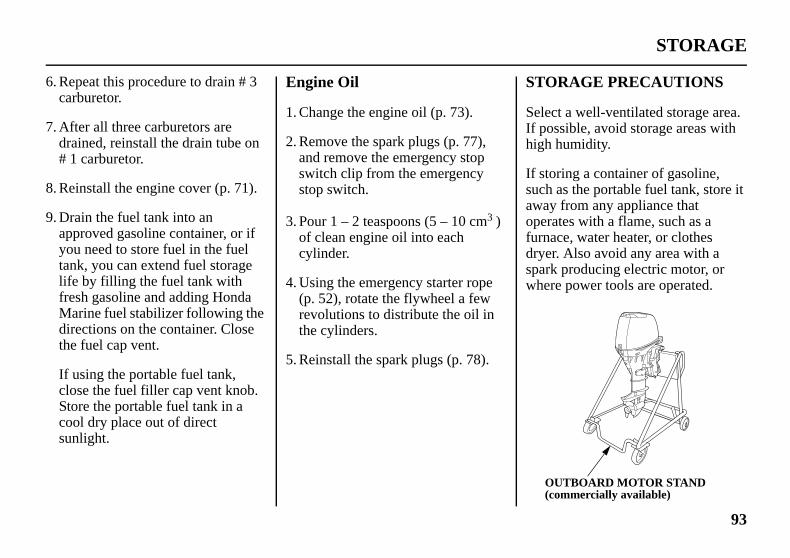
93
STORAGE
STORAGE PRECAUTIONS
Select a well-ventilated storage area. If possible, avoid storage areas with high humidity.
If storing a container of gasoline, such as the portable fuel tank, store it away from any appliance that operates with a flame, such as a furnace, water heater, or clothes dryer. Also avoid any area with a spark producing electric motor, or where power tools are operated.
OUTBOARD MOTOR STAND (commercially available)
31ZW26320.book 93 ページ 2013年9月30日 月曜日 午後7時35分
6. Reca
7. Adr#
8. Re
9. DapyotaliffreMdith
If clStcosu
peat this procedure to drain # 3 rburetor.
fter all three carburetors are ained, reinstall the drain tube on 1 carburetor.
install the engine cover (p. 71).
rain the fuel tank into an proved gasoline container, or if u need to store fuel in the fuel
nk, you can extend fuel storage e by filling the fuel tank with sh gasoline and adding Honda arine fuel stabilizer following the rections on the container. Close e fuel cap vent.
using the portable fuel tank, ose the fuel filler cap vent knob. ore the portable fuel tank in a ol dry place out of direct nlight.
Engine Oil
1. Change the engine oil (p. 73).
2. Remove the spark plugs (p. 77), and remove the emergency stop switch clip from the emergency stop switch.
3. Pour 1 – 2 teaspoons (5 – 10 cm3 ) of clean engine oil into each cylinder.
4. Using the emergency starter rope (p. 52), rotate the flywheel a few revolutions to distribute the oil in the cylinders.
5. Reinstall the spark plugs (p. 78).

31ZW26320.book 94 ページ 2013年9月30日 月曜日 午後7時35分
94
STO
If thremowe rmouavai
If it motocarbengithe o
Posicarbwith
RAGE
e outboard motor will be ved from the boat for storage,
ecommend storing it vertically by nting it on a commercially lable stand.
is necessary to store the outboard r horizontally, drain the
uretors (p. 92), and drain the ne oil (p. 73), before removing utboard motor from the boat.
tion the outboard motor with its uretor side down, and cushion it protective packing material.
Any other horizontal storage position may cause damage to the outboard motor or oil leakage.
Cover the outboard motor to keep out dust. Do not use plastic sheet as a dust cover. A nonporous cover will trap moisture, promoting rust and corrosion.
REMOVAL FROM STORAGE
Check your outboard motor as described in the BEFORE OPERATION chapter of this manual.
If the cylinders were coated with oil during storage preparation, the engine may smoke briefly at startup. This is normal.
CASE PROTECTOR

95
TRANSPORTINGAll Types
The preferred method is to leave the engine in the normal running position, but if there is insufficient road clearance, you can tilt the outboard motor using a commercially available outboard motor support bar available through your dealer. Refer to the manufacturer’s instructions for using an outboard motor support bar.
OUTBOARD MOTOR SUPPORT BAR (commercially available)
31ZW26320.book 95 ページ 2013年9月30日 月曜日 午後7時35分
WITINS
Wheoutbdiscport
SHG(lon
Tighto prmov
S
H OUTBOARD MOTOR TALLED ON BOAT
n trailering a boat with the oard motor attached, always onnect the fuel line from the able fuel tank.
and LHG Types g tiller handle)
ten the steering friction adjuster event the outboard motor from ing while trailering the boat.
LRG, SRT and LRT Types (remote control)
Use an outboard motor support bar to prevent the outboard motor from moving while trailering the boat. Refer to the manufacturer’s instructions for using an outboard motor support bar.
TEERING FRICTION ADJUSTER
TO INCREASE FRICTION (LOCK)
TO DECREASE FRICTION (FREE)

To carry, hold the outboard motor by the carrying handle, or hold by the carrying handle and the lug beneath the engine cover latch, as shown.
Lifting the outboard motor by the engine cover, or using the installed outboard motor as a handle or lever to move the boat, can damage the outboard motor.
31ZW26320.book 96 ページ 2013年9月30日 月曜日 午後7時35分
96
TR
WITREM
Secuthe vshow
(Til
ANSPORTING
H OUTBOARD MOTOR OVED FROM BOAT
re the outboard motor in either ertical or horizontal position n on p. 93 and 94.
ler handle type)
LUG
CARRYING HANDLE

97
TRANSPORTING
3. Reinstall the engine cover.
When trailing or transporting the boat with the outboard motor attached, it is recommended that the outboard motor remain in normal running position, with the steering friction adjuster in the locked position (p. 95).
ENGINE COVER
31ZW26320.book 97 ページ 2013年9月30日 月曜日 午後7時35分
Whemotofollo
1. Reoulifou(c
HOHO
LIFEYE
n transporting the outboard r on a vehicle, perform the wing.
move the engine cover, lift the tboard motor using the engine ting eye, and place on the tboard motor stand ommercially available).
2. Secure the outboard motor with the bolts, nuts and washers.
IST OK
TING

Correction
ttery connections.
).
ng procedure (p. 51), then take authorized Honda Marine dealer, anual.
31ZW26320.book 98 ページ 2013年9月30日 月曜日 午後7時35分
98
TAELE
Bat
Bat
Fus
Starpro
KING CARE OF UNEXPECTED PROBLEMSCTRIC STARTER WILL NOT OPERATE
Possible Cause
tery connections loose or corroded. Clean and tighten ba
tery discharged. Recharge battery.
e burnt out. Replace fuse (p. 103
ter malfunction, switch malfunction, or electrical blem in the starting circuit.
Use emergency startioutboard motor to anor refer to the shop m

99
NEXPECTED PROBLEMS
Correction
ncy stop switch.
or 49).
START position (p. 47).
, if the engine is warm (p. 50).
31ZW26320.book 99 ページ 2013年9月30日 月曜日 午後7時35分
ENG
Clip
Gea
Thr(lon
Fas
TAKING CARE OF U
INE WILL NOT STARTPossible Cause
not inserted in emergency stop switch. Insert clip in emerge
rshift lever or control lever not in neutral position. Shift to neutral (p. 47
ottle grip not in START position g tiller handle type).
Turn throttle grip to
t idle lever raised (remote control/side-mount type). Lower fast idle lever

Correction
p. 45).
b (p. 46).
p. 82 and 85).
arburetors (p. 92 and 93). Refill p. 79).
plugs (p. 77).
rk plugs. Start engine with the
to an authorized Honda Marine shop manual.
31ZW26320.book 100 ページ 2013年9月30日 月曜日 午後7時35分
100
TA
ENG
Out
Fue
Fue
Fue
Baddrai
Spa
Spa
Carmal
KING CARE OF UNEXPECTED PROBLEMS
INE WILL NOT START
Possible Cause
of fuel. Refuel (p. 79).
l vent closed (portable fuel tank). Open the vent knob (
l hose not primed. Squeeze priming bul
l filter or fuel tank filter clogged. Replace fuel filters (
fuel; outboard motor stored without treating or ning gasoline, or refueled with bad gasoline.
Drain fuel tank and cwith fresh gasoline (
rk plugs faulty, fouled, or improperly gapped. Gap or replace spark
rk plugs wet with fuel (flooded engine). Dry and reinstall spathrottle open.
buretor malfunction, fuel pump failure, ignition function, stuck valves, etc.
Take outboard motordealer, or refer to the

101
NEXPECTED PROBLEMS
Correction
START position (p. 47).
, unless engine is warm (p. 50).
p. 45).
b (p. 46).
p. 82 and 85).
arburetors (p. 92 and 93). Refill p. 79).
31ZW26320.book 101 ページ 2013年9月30日 月曜日 午後7時35分
HAR
Thr(lon
Fas
Fue
Fue
Fue
Baddrai
TAKING CARE OF U
D STARTING OR STALLS AFTER STARTINGPossible Cause
ottle grip not in START position g tiller handle type).
Turn throttle grip to
t idle lever raised (remote control/side-mount type). Lower fast idle lever
l vent closed (portable fuel tank). Open the vent knob (
l hose not primed. Squeeze priming bul
l filter or fuel tank filter clogged. Replace fuel filters (
fuel; outboard motor stored without treating or ning gasoline, or refueled with bad fuel.
Drain fuel tank and cwith fresh gasoline (

Correction
plugs (p. 77).
to an authorized Honda Marine shop manual.
Correction
reens.
to an authorized Honda Marine shop manual.
31ZW26320.book 102 ページ 2013年9月30日 月曜日 午後7時35分
102
TA
HAR
ENG
Spa
Carmal
Wat
Fau
KING CARE OF UNEXPECTED PROBLEMS
D STARTING OR STALLS AFTER STARTING
INE OVERHEATS
Possible Cause
rk plugs faulty, fouled, or improperly gapped. Gap or replace spark
buretor malfunction, fuel pump failure, ignition function, etc.
Take outboard motordealer, or refer to the
Possible Cause
er intake screens clogged. Clean water intake sc
lty thermostat or water pump. Take outboard motordealer, or refer to the

103
NEXPECTED PROBLEMS
4. Reinstall the fuse cover and the engine cover.
Before further operation, try to determine and correct the electrical problem that caused the fuse to burn out. An uncorrected electrical problem may cause the fuse to burn out again.
10A FUSE FUSE COVER
SPARE 10A FUSE
BLOWN FUSE
31ZW26320.book 103 ページ 2013年9月30日 月曜日 午後7時35分
BATCHSTAOPE
The elecprotthe fcharstartcan start
The the 1out, and oper
Fus
1. Wth
2. Re
TAKING CARE OF U
TERY WILL NOT ARGE AND ELECTRIC RTER WILL NOT RATE
battery-charging circuit and the tric starter relay circuit are ected by the 15-ampere fuse. If use burns out, the engine will not ge the battery, and the electric er will not operate. The engine be started using the emergency er rope.
ignition switch is protected by 0-ampere fuse. If the fuse burns the engine will not start or run, the power trim/tilt switch will not ate.
e Replacement
ith the engine stopped, remove e engine cover (p. 71).
move the fuse cover.
3. Remove and inspect the fuse. If a fuse is burnt out, install a replacement fuse of the specified rating. The outboard motor is supplied with a spare fuse in each fuse holder.
DESIGNATED FUSE RATING: 15A, 10A
Never use a fuse with a rating greater than specified. Serious damage to the electrical system could result.
FUSE COVER 15A FUSE
SPARE 15A FUSE

If low oil pressure activates the engine protection system, stop the engine, check the engine oil level (p. 72), and add oil if needed.
With the engine oil at the recommended level, restart the engine. If the lubrication system is OK, the green indicator light should come on within 30 seconds, and the engine will respond normally to throttle grip or control lever operation.
If the engine protection system remains activated after 30 seconds, return to the nearest boat landing, and have the outboard motor inspected by an authorized Honda Marine dealer.
31ZW26320.book 104 ページ 2013年9月30日 月曜日 午後7時35分
104
TA
OILGOSPE
SHG(lon
LRG[remtype
BU
KING CARE OF UNEXPECTED PROBLEMS
PRESSURE INDICATOR ES OFF AND ENGINE ED IS LIMITED
If oil pressure becomes low, the green indicator will go off, and the engine protection system will limit engine speed. If you are at cruising speed, engine speed will decrease automatically.
Remote control type is equipped with a buzzer that sounds continuously when the green indicator goes off. The buzzer sound stops below an engine speed of 1,400 rpm.
Low oil pressure may be the result of a low engine oil level, or there may be a problem with the engine lubrication system.
If the throttle is closed suddenly after full throttle operation, engine speed may drop below the specified idle rpm, and that could activate the engine protection system momentarily.
and LHG Types g tiller handle)
, SRT and LRT Types ote control (side-mount
)]
(GREEN)
(GREEN)
ZZER

105
NEXPECTED PROBLEMS
If overheating activates the engine protection system, idle the engine in neutral, and check the cooling system indicator.
If water is flowing from the cooling system indicator, continue idling for 30 seconds. If the cooling system is OK, the red indicator should go off within 30 seconds, and the engine will respond normally to throttle grip or control lever operation.
COOLING SYSTEM INDICATOR
31ZW26320.book 105 ページ 2013年9月30日 月曜日 午後7時35分
OVCOSPE
SHG(lon
LRG[remtype
BU
TAKING CARE OF U
ERHEAT INDICATOR MES ON AND ENGINE ED IS LIMITED
If the engine overheats, the red indicator will come on, and the engine protection system will limit engine speed. If you are at cruising speed, engine speed will decrease gradually. When normal engine temperature is restored, the engine speed will gradually rise to normal engine speed.
If the condition persists for another 20 seconds, the engine will shut off.
Remote control types are equipped with a buzzer that sounds when the red indicator comes on.
Engine overheating may be the result of clogged water intake screens, or there may be a problem with the cooling system thermostat or water pump.
and LHG Types g tiller handle)
, SRT and LRT Types ote control (side-mount
)]
(RED)
(RED)
ZZER

3. Change the engine oil as described on p. 73 and 75. If there was water in the engine crankcase, or if the used engine oil showed signs of water contamination, then a second engine oil change should be performed after running the engine for half an hour.
4. Remove the flywheel cover (p. 52). Remove the spark plugs (p. 77), and remove the clip from the emergency stop switch. Pull the emergency starter rope, rotate the flywheel a few revolutions to completely expel any water from the cylinders.
Direction to pull
EMERGENCY STARTER ROPE
31ZW26320.book 106 ページ 2013年9月30日 月曜日 午後7時35分
106
TA
If thcoolengiinspclogscrethe rengiindic
If ththe cengiactivthe noutbauth
KING CARE OF UNEXPECTED PROBLEMS
ere is no water flowing from the ing system indicator, stop the ne, and tilt the outboard motor to ect the water intake screens. If ged, clean the water intake ens, return the outboard motor to unning position, restart the ne, and check the cooling system ator again.
ere is still no water flowing from ooling system indicator, or if the ne protection system remains ated after 30 seconds, return to earest boat landing, and have the oard motor inspected by an orized Honda Marine dealer.
SUBMERGED OUTBOARD MOTORA submerged outboard motor must be serviced immediately after it is recovered from the water in order to minimize corrosion.
If there is a Honda Marine dealership nearby, take the outboard motor to the dealer immediately. If you are far from a dealer, proceed as follows:
1. Remove the engine cover, and rinse the outboard motor with fresh water to remove salt water, sand, mud, etc.
2. Drain the carburetors as described on p. 92.

107
NEXPECTED PROBLEMS
7. Attempt to start the engine.
If the engine fails to start, remove the spark plugs, dry them, then reinstall the spark plugs and attempt to start the engine again.
If the engine starts, and no mechanical damage is evident, continue to run the engine for a half hour or longer. Be sure the water level is at least 2 inches (5 cm) above the antiventilation plate to avoid overheating and water pump damage.
8. As soon as possible, take the outboard motor to an authorized Honda Marine dealer for inspection and service.
31ZW26320.book 107 ページ 2013年9月30日 月曜日 午後7時35分
If sumcowrure
Woprerestoda
TAKING CARE OF U
the engine was running when it bmerged, there may be echanical damage, such as bent nnecting rods. If the engine binds hen cranked, do not attempt to n the engine until it has been paired.
hen cranking the engine with an en ignition circuit (spark plugs moved from the ignition circuit), move the clip from the emergency p switch to prevent possible mage to the ignition system.
5. Pour a teaspoon of engine oil into each spark plug hole, and then pull the emergency starter rope several times to lubricate the inside of the cylinders.
6. Reinstall the spark plugs, and put the emergency stop switch clip into the emergency stop switch.

The engine serial number is stamped on the cylinder block under the starter motor which is located in the front of the engine.
Engine serial number:
STARTER MOTOR
ENGINE SERIAL NUMBER
31ZW26320.book 108 ページ 2013年9月30日 月曜日 午後7時35分
108
TESeri
Reconumand provthesand warr
CHNICAL INFORMATIONal Number Locations
rd the product identification ber, the engine serial number, the date of purchase in the space ided on this page. You will need e numbers when ordering parts, when making technical or anty inquiries (p. 118).
The product identification number is stamped on a plate attached on the left side of the stern bracket.
Product identification number:
Date of purchase:
PRODUCT IDENTIFICATION NUMBER

109
HNICAL INFORMATION
Battery
For complete information, refer to the battery manufacturer’s instructions.
Minimum Requirements
12V-52Ah/5HR (65Ah/20HR) (CCA 420)
31ZW26320.book 109 ページ 2013年9月30日 月曜日 午後7時35分
CarHig
At ameteair-fPerfconsrich plugOpefromcertitime
Highimprthe cyour(900yourdeal
Youappraltituoutb
TEC
buretor Modification for h Altitude Operation
ltitudes above 3,000 feet (900 rs), the standard carburetor uel mixture will be too rich. ormance will decrease, and fuel umption will increase. A very mixture will also foul the spark and cause hard starting.ration at an altitude that differs that at which this engine was fied, for extended periods of , may increase emissions.
altitude operation can be oved by specific modifications to arburetor. If you usually operate outboard motor at 3,000 feet meters) or above, consult with authorized Honda Marine er.
r dealer can determine the opriate carburetor settings for the de at which you operate your
oard motor.
Even with carburetor modification, engine horsepower will decrease about 3.5% for each 1,000-foot (300-meter) increase in altitude. The effect of altitude on horsepower will be greater than this if no carburetor modification is made.
When the carburetor has been modified for high altitude operation, the air-fuel mixture will be too lean for low altitude use. Operation at altitudes below 3,000 feet (900 meters) with a modified carburetor may cause the engine to overheat and result in serious engine damage. For use at low altitudes, have an authorized Honda Marine dealer return the carburetor to original factory specifications.

Tampering and Altering
Tampering is a violation of Federal and California law.
Tampering with or altering the emission control system may increase emissions beyond the legal limit. Among those acts that constitute tampering are:
• Removal or alteration of any part of the intake, fuel, or exhaust systems.
• Alterations that would cause the engine to operate outside its design parameters.
31ZW26320.book 110 ページ 2013年9月30日 月曜日 午後7時35分
110
TE
EmInfo
Sou
The carband hydris vecertaphotto sunot rtoxic
Honratiosystecarband
CHNICAL INFORMATION
ission Control System rmation
rce of Emissions
combustion process produces on monoxide, oxides of nitrogen, hydrocarbons. Control of ocarbons and oxides of nitrogen ry important because, under in conditions, they react to form ochemical smog when subjected nlight. Carbon monoxide does eact in the same way, but it is .
da utilizes appropriate air/fuel s and other emissions control ms to reduce the emissions of
on monoxide, oxides of nitrogen, hydrocarbons.
The U.S., California Clean Air Acts, and Environment Canada
EPA, California, and Canadian regulations require all manufacturers to furnish written instructions describing the operation and maintenance of emission control systems.
The following instructions and procedures must be followed in order to keep the emissions from your Honda engine within the emission standards.

111
HNICAL INFORMATION
A manufacturer of an aftermarket part assumes the responsibility that the part will not adversely affect emission performance. The manufacturer or rebuilder of the part must certify that use of the part will not result in a failure of the engine to comply with emission regulations.
Maintenance
Follow the maintenance schedule on (p. 68 and 69). Remember that this schedule is based on the assumption that your machine will be used for its designed purpose. Sustained high-load operation, or use in unusual conditions, will require more frequent service.
31ZW26320.book 111 ページ 2013年9月30日 月曜日 午後7時35分
ProEmi
If yofolloengiserv
• Hsta
• Ro
• M
• A
• Blco
TEC
blems That May Affect ssions
u are aware of any of the wing symptoms, have your ne inspected and repaired by your icing dealer.
ard starting or stalling after rting.
ugh idle.
isfiring or backfiring under load.
fterburning (backfiring).
ack exhaust smoke or high fuel nsumption.
Replacement Parts
The emission control systems on your Honda engine were designed, built, and certified to conform with EPA and California emission regulations. We recommend the use of Honda Genuine parts whenever you have maintenance done. These original-design replacement parts are manufactured to the same standards as the original parts, so you can be confident of their performance. The use of replacement parts that are not of the original design and quality may impair the effectiveness of your emission control system.

ne Engine
es:
ifestyle and environment.
40 percent less gas and oil than nes, saving money and resources.
onsumer for worry-free operation.
:
31ZW26320.book 112 ページ 2013年9月30日 月曜日 午後7時35分
112
TE
StarUS, Islan
A Stoutbthe rReso
CHNICAL INFORMATION
LabelPuerto Rico, and US Virgin ds
ar label was applied to this oard motor in accordance with equirements of the California Air urces Board.
The Star Label means Cleaner Mari
The Symbol for Cleaner Marine Engin
Cleaner Air and Water - for healthier l
Better Fuel Economy - burns up to 30 -conventional carbureted two-stroke engi
Longer Emission Warranty - protects c
This engine has been certified as a

113
HNICAL INFORMATION
t meet the Air Resources Board’s e engine 2001 exhaust emission rds have 75% lower emissions than nes. These engines are equivalent to e engines.
t meet the Air Resources Board’s e engine 2004 exhaust emission rds have 20% lower emissions than
at meet the Air Resources Board’s e engine 2008 exhaust emission marine engine 2003-2008 exhaust se standards have 65% lower engines.
t meet the Air Resources Board’s 09 exhaust emission standards. e engines may also comply with these rds have 90% lower emissions than
Cleaner Watercraft - Get the Facts1-800-END-SMOG
www.arb.ca.gov
31ZW26320.book 113 ページ 2013年9月30日 月曜日 午後7時35分
TEC
One Star Low Emission
Two Stars Very Low Emission
Three Stars Ultra Low Emission
Four Stars Super Ultra Low Emission
The one-star label identifies engines thaPersonal Watercraft and Outboard marinstandards. Engines meeting these standaconventional carbureted two-stroke engithe U.S. EPA’s 2006 standards for marin
The two-star label identifies engines thaPersonal Watercraft and Outboard marinstandards. Engines meeting these standaOne Star-Low Emission engines.
The three-star label identifies engines thPersonal Watercraft and Outboard marinstandards or the Sterndrive and Inboard emission standards. Engines meeting theemissions than One Star-Low Emission
The four-star label identifies engines thaSterndrive and Inboard marine engine 20Personal Watercraft and Outboard marinstandards. Engines meeting these standaOne Star-Low Emission engines.

ULTRA LOW EMISSION12V – 10A
Water cooling with thermostatWater exhaust
DR7EA (NGK)X22ESR-U (DENSO)
Diaphragm typeUnleaded gasoline
(86 pump octane or higher)6.6 US gal (25 L)
Forward-Neutral-Reverse (dog type)40° right and left
4 stages(8°, 12°, 16°, 20°)
Stageless (64°)
– 4° to 12°
0.024 – 0.028 in(0.6 – 0.7 mm)
See page 77
950 ± 50 rpm See shopmanual
ake: haust:
0.12 ± 0.02 mm 0.20 ± 0.02 mm
See shopmanual
No other adjustment is needed
nd using the ICOMIA standard 28/23.
31ZW26320.book 114 ページ 2013年9月30日 月曜日 午後7時35分
114
TE
MODDescTypeOverOverOver
Tran(wheangleDry m[weigRateFull EngiDispStartIgnitLubrSpec
Oil c
Spe
* W
Hon
CHNICAL INFORMATION
Tuneup
EL BF25Dription code BATJ
HGall length 28.3 in (720 mm)all width 14.8 in (375 mm)all height S 47.0 in (1,195 mm)
L 52.0 in (1,320 mm)som height n transom at 12°)
S 17.0 in (431 mm)
L 21.7 in (552 mm)ass
ht]*S 176.4 lbs (80.0 kg)L 180.8 lbs (82.0 kg)
d power 18.7 kW (25 HP)throttle range 5,000 – 6,000 rpmne type 4 stroke OHC in-line 3 cylinderlacement 33.7 cu-in (552 cm3)er system Electric starterion system Digital ICM (Ignition Control Module)ication system Trochoid pump pressure lubricationified oil Engine: API standard (SG, SH or SJ)
SAE/FC-W 5W-30Gear case: API standard (GL-4) SAE 90
Hypoid gear oilapacity Engine: 1.7 US qt (1.6 L)
Without oil filter change 1.8 US qt (1.7 L) With oil filter change
Gear case: 0.29 US qt (0.27 L)
CARB star labelD.C. outputCooling systemExhaust systemSpark plugs
Fuel pumpFuel
Tank capacityGear changeSteering angleTransom angle
Tilt angle (when transom angle at 12°)Trim angle (when transom angle at 12°)
Spark plug gap
Idle speed
Valve clearance (cold)
IntEx
Other specifications
cifications
ith propeller
da outboard motors are power rated in accordance with NMMA procedures a

115
HNICAL INFORMATION
ULTRA LOW EMISSION12V – 10A
Water cooling with thermostatWater exhaust
DR7EA (NGK)X22ESR-U (DENSO)
Diaphragm typeUnleaded gasoline
(86 pump octane or higher)6.6 US gal (25 L)
Forward-Neutral-Reverse (dog type)40° right and left
4 stages(8°, 12°, 16°, 20°)
Stageless (64°)
– 4° to 12°
0.024 – 0.028 in(0.6 – 0.7 mm)
See page 77
950 ± 50 rpm See shopmanual
ake: haust:
0.12 ± 0.02 mm 0.20 ± 0.02 mm
See shopmanual
No other adjustment is needed
nd using the ICOMIA standard 28/23.
31ZW26320.book 115 ページ 2013年9月30日 月曜日 午後7時35分
MODDescTypeOverOverOverTran(wheangleDry m[weigRateFull EngiDispStartIgnitLubrSpec
Oil c
Spe
* W
Hon
TEC
Tuneup
EL BF25Dription code BATJ
RG RTall length 25.2 in (640 mm)all width 14.8 in (375 mm)all height L 52.0 in (1,320 mm)som height n transom at 12°)
L 21.7 in (552 mm)
ass ht]*
L 170.9 lbs (77.5 kg) 175.3 lbs (79.5 kg)
d power 18.7 kW (25 HP)throttle range 5,000 – 6,000 rpmne type 4 stroke OHC in-line 3 cylinderlacement 33.7 cu-in (552 cm3)er system Electric starterion system Digital ICM (Ignition Control Module)ication system Trochoid pump pressure lubricationified oil Engine: API standard (SG, SH or SJ)
SAE/FC-W 5W-30Gear case: API standard (GL-4) SAE 90
Hypoid gear oilapacity Engine: 1.7 US qt (1.6 L)
Without oil filter change 1.8 US qt (1.7 L) With oil filter change
Gear case: 0.29 US qt (0.27 L)
CARB star labelD.C. outputCooling systemExhaust systemSpark plugs
Fuel pumpFuel
Tank capacityGear changeSteering angleTransom angle
Tilt angle (when transom angle at 12°)Trim angle (when transom angle at 12°)
Spark plug gap
Idle speed
Valve clearance (cold)
IntEx
Other specifications
cifications
ith propeller
da outboard motors are power rated in accordance with NMMA procedures a

ULTRA LOW EMISSION12V – 10A
Water cooling with thermostatWater exhaust
DR7EA (NGK)X22ESR-U (DENSO)
Diaphragm typeUnleaded gasoline
(86 pump octane or higher)6.6 US gal (25 L)
Forward-Neutral-Reverse (dog type)40° right and left
4 stages(8°, 12°, 16°, 20°)
Stageless (64°)
– 4° to 12°
0.024 – 0.028 in(0.6 – 0.7 mm)
See page 77
950 ± 50 rpm See shopmanual
ake: haust:
0.12 ± 0.02 mm 0.20 ± 0.02 mm
See shopmanual
No other adjustment is needed
nd using the ICOMIA standard 28/23.
31ZW26320.book 116 ページ 2013年9月30日 月曜日 午後7時35分
116
TE
MODDescTypeOverOverOver
Tran(wheangleDry m[weigRateFull EngiDispStartIgnitLubrSpec
Oil c
Spe
* W
Hon
CHNICAL INFORMATION
Tuneup
EL BF30Dription code BAUJ
HGall length 28.3 in (720 mm)all width 14.8 in (375 mm)all height S 47.0 in (1,195 mm)
L 52.0 in (1,320 mm)som height n transom at 12°)
S 17.0 in (431 mm)
L 21.7 in (552 mm)ass
ht]*S 176.4 lbs (80.0 kg)L 180.8 lbs (82.0 kg)
d power 22.4 kW (30 HP)throttle range 5,000 – 6,000 rpmne type 4 stroke OHC in-line 3 cylinderlacement 33.7 cu-in (552 cm3)er system Electric starterion system Digital ICM (Ignition Control Module)ication system Trochoid pump pressure lubricationified oil Engine: API standard (SG, SH or SJ)
SAE/FC-W 5W-30Gear case: API standard (GL-4) SAE 90
Hypoid gear oilapacity Engine: 1.7 US qt (1.6 L)
Without oil filter change 1.8 US qt (1.7 L) With oil filter change
Gear case: 0.29 US qt (0.27 L)
CARB star labelD.C. outputCooling systemExhaust systemSpark plugs
Fuel pumpFuel
Tank capacityGear changeSteering angleTransom angle
Tilt angle (when transom angle at 12°)Trim angle (when transom angle at 12°)
Spark plug gap
Idle speed
Valve clearance (cold)
IntEx
Other specifications
cifications
ith propeller
da outboard motors are power rated in accordance with NMMA procedures a

117
HNICAL INFORMATION
ULTRA LOW EMISSION12V – 10A
Water cooling with thermostatWater exhaust
DR7EA (NGK)X22ESR-U (DENSO)
Diaphragm typeUnleaded gasoline
(86 pump octane or higher)6.6 US gal (25 L)
Forward-Neutral-Reverse (dog type)40° right and left
4 stages(8°, 12°, 16°, 20°)
Stageless (64°)
– 4° to 12°
0.024 – 0.028 in(0.6 – 0.7 mm)
See page 77
950 ± 50 rpm See shopmanual
ake: haust:
0.12 ± 0.02 mm 0.20 ± 0.02 mm
See shopmanual
No other adjustment is needed
nd using the ICOMIA standard 28/23.
31ZW26320.book 117 ページ 2013年9月30日 月曜日 午後7時35分
MODDescTypeOverOverOver
Tran(wheangleDry m[weigRateFull EngiDispStartIgnitLubrSpec
Oil c
Spe
* W
Hon
TEC
Tuneup
EL BF30Dription code BAUJ
RG RTall length 25.2 in (640 mm)all width 14.8 in (375 mm)all height S 47.0 in (1,195 mm)
L 52.0 in (1,320 mm)som height n transom at 12°)
S 17.0 in (431 mm)L 21.7 in (552 mm)
ass ht]*
S ——————— 170.9 lbs (77.5 kg)L 170.9 lbs (77.5 kg) 175.3 lbs (79.5 kg)
d power 22.4 kW (30 HP)throttle range 5,000 – 6,000 rpmne type 4 stroke OHC in-line 3 cylinderlacement 33.7 cu-in (552 cm3)er system Electric starterion system Digital ICM (Ignition Control Module)ication system Trochoid pump pressure lubricationified oil Engine: API standard (SG, SH or SJ)
SAE/FC-W 5W-30Gear case: API standard (GL-4) SAE 90
Hypoid gear oilapacity Engine: 1.7 US qt (1.6 L)
Without oil filter change 1.8 US qt (1.7 L) With oil filter change
Gear case: 0.29 US qt (0.27 L)
CARB star labelD.C. outputCooling systemExhaust systemSpark plugs
Fuel pumpFuel
Tank capacityGear changeSteering angleTransom angle
Tilt angle (when transom angle at 12°)Trim angle (when transom angle at 12°)
Spark plug gap
Idle speed
Valve clearance (cold)
IntEx
Other specifications
cifications
ith propeller
da outboard motors are power rated in accordance with NMMA procedures a

important to work to resolve any differences at the dealership level. If the service personnel are unable to assist you, please discuss your concerns with the dealer management such as the Service Manager or the dealership’s owner.If you need to contact Honda regarding your experiences with your Honda product or with your dealer, please contact the Honda office in your region:
American Honda Motor Co., Inc.Marine Division Customer Relations Office 4900 Marconi Drive Alpharetta, GA 30005-8847 Telephone (770) 497 – 6400 M-F 8:30 am-7:00 pm (Eastern Time Zone)
Honda Canada Inc.Customer Relations Office 180 Honda Boulevard Markham, Ontario L6C 0H9 Tel: 1-888-946-6329 (Toll free) Fax: 1-877-939-0909 (Toll free)
31ZW26320.book 118 ページ 2013年9月30日 月曜日 午後7時35分
118
COHon(UnU.S.
Thesaddimainoutb
ShoThismainprocby aAvaMarmarishop
ParThisillusThe Hon
NSUMER INFORMATIONda Publications
ited States, Puerto Rico, and Virgin Islands)
e publications will give you tional information for taining and repairing your oard motor.
p Manual manual covers complete tenance and overhaul edures. It is intended to be used skilled technician.ilable through your Honda ine dealer or visit http://ne.honda.com/owners/manuals/-manuals.
ts Catalog manual provides complete, trated parts lists.catalog is available through your da Marine dealer.
Accessory CatalogYour authorized Honda Marine dealer offers a wide selection of accessories (optional equipment, oils, and lubricants) to enhance your boating experience.Visit http://marine.honda.com and click on PARTS & ACCESSORIES to see the entire catalog of accessories.
Customer Service Information
Contacting HondaYour Owner’s Manual was written to cover most of the questions you might ask about your Honda. Any questions not answered in the Owner’s Manual can be answered by your Honda dealer. If your dealer doesn’t have an immediate answer, they should be able to get it for you.
If you have a difference of opinion with your dealer, please remember that each dealership is independently owned and operated. That’s why it’s

119
NSUMER INFORMATION
It is important to realize that your warranty applies to defects in material or workmanship of your Honda. Your warranty coverage does not apply to normal wear or deterioration associated with using your Honda outboard motor.
Your warranty coverage will not be voided if you choose to perform your own maintenance. However, you should have the proper tools and service information and be mechanically qualified. Failures that occur due to modifications, improper maintenance, or service are not covered.
31ZW26320.book 119 ページ 2013年9月30日 月曜日 午後7時35分
Pleainfo
• Yonu
• M
• D
• Nde
• Nde
• Aco
CO
se include the following rmation in your communication:
ur name, address and telephone mber (complete with area code)
odel and complete serial number
ate of purchase
ame and location of selling aler
ame and location of servicing aler (if different)
detailed description of your ncerns
Warranty Coverage
Your new Honda is covered by the following warranties:
• Distributor’s Limited Warranty• Emission Control System Warranty
Please read the warranty statements contained in this manual. There are responsibilities, restrictions, and exclusions that apply to these warranties.
To obtain warranty service you must take your Honda outboard motor, together with proof of original retail purchase date, at your expense, to a Honda engine dealer or distributor authorized to sell that product in the United States, Puerto Rico, the U.S. Virgin Islands or Canada.

31ZW26320.book 120 ページ 2013年9月30日 月曜日 午後7時35分
120
CO
War
PleamainincluAddappl(sucetc.)
As tyourauthprobyourwarrHowaddi
If yocoveis beof yo
Somintenmisuaren
NSUMER INFORMATION
ranty Service
se remember that recommended tenance interval servicing is not ded in your warranty coverage.
itionally, your warranty does not y to the normal wear of items h as spark plug(s), water pump, .
he owner of a Honda product, servicing dealer may ask you to orize an inspection. If the lem is covered under warranty, dealer will perform any anty repairs for you at no cost. ever, you may be responsible for tional non-warranty charges.
u have questions about warranty rage or the nature of the repair, it st to talk to the service manager ur Honda dealer.
etimes, in spite of the best tions of all concerned, a nderstanding may occur. If you ’t satisfied with your dealer’s
handling of the situation, we suggest you discuss your problem with the appropriate member of the dealership’s management team. If the problem has already been reviewed with the appropriate manager of the Service, Parts, or Sales department, contact the owner of the dealership or their designated representative.

121
NSUMER INFORMATION
sed in the United States, Puerto Rico, utboards purchased in Canada. d.
nt distributed by American Honda orgia 30005-8847.
ting dealer). Specialty Manufacturing Co. (Outboard Jets).
f original retail purchase)RENTAL STATE/LOCAL/FEDERAL
GOVERNMENTs 24 monthss 24 months
hey were purchased.
31ZW26320.book 121 ページ 2013年9月30日 月曜日 午後7時35分
WarThe or thThe
Uni
DistThisMot
(1) M(2) 3
All mAll MRelaBF2 and oAll mtiller
CO
ranty StatementsAmerican Honda Distributor’s Limited Warranty applies to outboards purchae U.S. Virgin Islands. The Honda Canada Distributor’s Warranty applies to oproduct warranty is only valid in the country where the product was purchase
ted states, Puerto Rico and Virgin Islands
ributor’s Limited Warranty warranty is limited to Honda Outboard Motors and related original equipmeor Co., Inc., Power Equipment Division, 4900 Marconi Drive, Alpharetta, Ge
odels purchased prior to July 1, 2008 (unless previously purchased with True-5 warranty from a participa5, 65, & 105 Jet models: Jet pump assembly is a dealer installed option. Jet pump warranty is provided by
Products Covered by Warranty: Length of Warranty: (from date oNONCOMMERCIAL/
NONRENTALCOMMERCIAL/
odels purchased before July 1, 2008(1) (2) 36 months 12 monthodels purchased on or after July 1, 2008(2) 60 months 12 month
ted original equipment items: through BF30 models: Portable fuel tank riginal propeller. odels: Primer bulb/fuel line assembly and
handle.
The same duration as the outboard with which t

ty Service:
xpense, take your Honda Outboard the original purchase date to any rized to service Honda Outboard d States, Puerto Rico, or the U.S. ng the dealer’s normal business hours. obtain warranty service, or are warranty service you receive, take the st, contact the owner of the dealership this should resolve the problem. uld require further assistance, write or
ine Customer Relations. Please see age 118.
31ZW26320.book 122 ページ 2013年9月30日 月曜日 午後7時35分
122
COTo QThe AmeHonStatelimieachtime
WhaWarAmepart workwarrwill replaAme
All ppart partswarr
NSUMER INFORMATIONualify for This Warranty:
Honda Outboard Motor must be purchased from rican Honda or a dealer authorized by American da to sell Honda Outboard Motors in the United s, Puerto Rico, or the U.S. Virgin Islands. This
ted warranty applies to the first retail purchaser and subsequent owner during the applicable warranty period.
t American Honda Will Repair or Replace Under ranty:rican Honda will repair or replace, at its option, any that is proven to be defective in material or manship under normal use during the applicable anty time period. Warranty repairs and replacements be made without charge for parts or labor. Anything ced under warranty becomes the property of rican Honda Motor Company, Inc.
arts replaced under warranty will be considered as of the original product and any warranty on those will expire coincidentally with the original product anty.
To Obtain Warran
You must, at your eMotor and proof of dealer who is authoMotors in the UniteVirgin Islands, duriIf you are unable todissatisfied with thefollowing steps: Firinvolved; normally However, if you shocall the Honda MarContacting Honda p

123
NSUMER INFORMATION
or towing charges, in and out of water cian travel time organisms on outboard motor or internalhas ever been declared a total loss or y a financial institution or insurer, or ed a ‘‘salvage’’ or similar title under
equential damage and limitation of :sclaims any responsibility for loss of utboard, revenue, or the equipment in is installed, transportation, any other incidental or consequential d warranties are limited to the ten limited warranty.allow limitations on how long an sts and/or do not allow the exclusion dental or consequential damages, so s and limitations may not apply to you. you specific legal rights, and you may ts which vary from state to state.
31ZW26320.book 123 ページ 2013年9月30日 月曜日 午後7時35分
ExcThis• Co
im• Co
alth
• OopM
• Paan
• N• Fu
th• O
w• U
noot
• In• Th
oror
• Cocochda
CO
lusions: warranty does not extend to the following:nditions caused by lack of routine maintenance or proper storage (as outlined in the Owner’s Manual)nditions caused by the use of propeller (s) that do not
low the outboard motor to run in its recommended full rottle rpm rangeperation inconsistent with the recommended eration/duty cycle (as outlined in the Owner’s anual)rts affected or damaged by an abuse, submersion d/or collisionormal wear and tearel contamination and water entering engine through
e fuel intake, air intake or exhaust systemperation with fuels, oils, additives and lubricants hich are not suitable for use in the productse in an application for which the outboard motor was t designed, such as racing or competitive use or any her misuse or neglectcorporation of unsuitable attachments or partse unauthorized alteration, improper installation and/
rigging, or any causes other than defects in material workmanshiprrosion to steering system or electrical components, rrosion due to electrolysis, water born foreign emicals, improper service or corrosion caused by mage or abuse
• Reimbursement fcharges, or techni
• Growth of marinesurfaces, external
• Any product that sold for salvage bthat has been issuany state’s law.
Disclaimer of consimplied warrantiesAmerican Honda ditime or use of the owhich the outboardcommercial loss, ordamage. Any implieduration of this writSome states do not implied warranty laor limitation of incithe above exclusionThis warranty givesalso have other righ

ve in material or workmanship under he applicable warranty time period. nder warranty becomes the property Motor Company, Inc. All parts anty will be considered as part of the any warranty on those parts will y with the original product warranty.
lacement parts, installed by a dealer y American Honda to sell them, will ced under warranty without charge for talled by anyone else, accessories and ill be repaired or replaced under arge for parts, but any labor charges bility of the purchaser.
tributed by American Honda Motor
f original retail purchase)Rental Local/State/Federal
Governments 3 months
hs 24 months
s 3 months
31ZW26320.book 124 ページ 2013年9月30日 月曜日 午後7時35分
124
CO
To Q1. Th
frodiseanbeeqcopr
2. Yono
WhaWarAmemari
AccThisCo.,
AcceEmisPortawateRepl
NSUMER INFORMATION
ualify for This Warranty:e accessories or replacement parts must be purchased m American Honda or a dealer, distributor, or
stributor’s dealer authorized by American Honda to ll those products in the United States, Puerto Rico, d the U.S. Virgin Islands. Parts and Accessories must purchased for installation on original Honda uipment or engines to be eligible for warranty verage. Installing parts and accessories on non-Honda oducts or engines voids this warranty.u must be the first retail purchaser. This warranty is t transferable to subsequent owners.
t American Honda Will Repair or Replace Under ranty:rican Honda will repair or replace, at its option, any ne product accessories or replacement parts that are
proven to be defectinormal use during tAnything replaced uof American Hondareplaced under warroriginal product andexpire coincidentall
Accessories and repwho is authorized bbe repaired or replaparts or labor. If insreplacement parts wwarranty without chwill be the responsi
essories and Replacement Parts warranty is limited to Honda Marine parts, accessories and apparel when dis Inc., 1919 Torrance Blvd., Torrance, California 90501-2746.Products Covered by Warranty: Length of Warranty: (from date o
Non Commercial Commercial/
ssories other than noted below 12 months 3 monthsion related accessories: ble fuel tanks, fuel line assemblies, and r/fuel separators
24 months 24 mont
acement Parts 6 months 3 month

125
NSUMER INFORMATION
d warranty lasts and/or do not allow itation of incidental or consequential ve exclusions and limitations may not arranty gives you specific legal rights,
ave other rights which vary from state
31ZW26320.book 125 ページ 2013年9月30日 月曜日 午後7時35分
To OYouMotoutbreplaHonUnitduri
ExcThisaffecapplotheattacinstaworkInstaengi
DiscimpAmetimeprodany implwrit
CO
btain Warranty Service: must, at your expense, take the Honda Outboard or product accessory or replacement part or the oard motor or boat on which the accessory or cement part is installed, and proof of purchase to any
da Marine authorized service facility or dealer in the ed States, Puerto Rico, or the U.S. Virgin Islands, ng normal business hours.
lusions: warranty does not extend to accessories or parts ted or damaged by collision, normal wear, use in an
ication for which the product was not designed or any r misuse, neglect, incorporation or use of unsuitable hments or parts, unauthorized alteration, improper llation, or any causes other than defects in material or manship of the product.lling parts and accessories on non-Honda products or nes voids this warranty.
laimer of consequential damage and limitation of lied warranties:rican Honda disclaims any responsibility for loss of or use of the outboard motor, or the boat on which the uct is installed, transportation, commercial loss, or other incidental or consequential damage. Any ied warranties are limited to the duration of this ten warranty. Some states do not allow limitations on
how long an impliethe exclusion or limdamages, so the aboapply to you. This wand you may also hto state.

proper maintenance of your outboard
rol system may include parts such as el injection system, the ignition c converter. Also included may be tors, and other emission-related
e condition exists, American Honda repair your outboard engine at no cost gnosis, parts, and labor.
ER’S WARRANTY
trol parts from model year 2010 and es are warranted for five years or 250 ever first occurs; or the length of the ributor’s Limited Warranty, whichever warranty coverage based on the y permitted for engines equipped with ed in § 2441 (a)(13)* or their
mission-related part on your engine is ranty, the part will be repaired or an Honda Motor Co., Inc.
f Regulations.
31ZW26320.book 126 ページ 2013年9月30日 月曜日 午後7時35分
126
CO
Em
YouU.S.AmecoveareadesiCalispar
CALWAYOUOBLThe Amethe eHonengistateAmeemisperio
NSUMER INFORMATION
ission Control System Warranty
r new Honda outboard engine complies with both the EPA and State of California emission regulations. rican Honda provides the same emission warranty rage for outboard engines sold in all 50 states. In all s of the United States your outboard engine must be gned, built, and equipped to meet the U.S. EPA and fornia Air Resources Board emission standard for k ignited marine engines.
IFORNIA EMISSION CONTROL RRANTY STATEMENT
R WARRANTY RIGHTS AND IGATIONS
California Air Resources Board (CARB) and rican Honda Motor Co., Inc. are pleased to explain mission control system warranty on your 2013-2014 da outboard engine. In California, new outboard nes must be designed, built, and equipped to meet the ’s stringent anti-smog standards.rican Honda Motor Co., Inc. must warrant the sion control system on your outboard engine for the ds of time listed below provided there has been no
abuse, neglect, or imengine.Your emission contthe carburetor or fusystem, and catalytihoses, belts, connecassemblies.Where a warrantablMotor Co., Inc. willto you including dia
MANUFACTURCOVERAGE:Select emission conlater outboard enginhours of use, whichHonda Marine Distis longer. However,hourly period is onlhour meters as definequivalent. If any edefective under warreplaced by Americ
* California Code o

127
NSUMER INFORMATION
istributor’s Limited Warranty, , from the date of delivery to the retail ranty is transferred to each subsequent ration of the warranty period.ll be made without charge for labor. All defective parts replaced
become the property of American nc. A list of warranty parts is on page nance items, such as spark plugs and e warranted parts list are warranted up lacement interval only.otor Co., Inc. is also liable for gine components caused by a failure rt during the warranty period.ed replacement parts will be used in any warranty repairs, and they will be arge to the owner. You may use any
defined in § 1900 (b)(20)* in the maintenance or repairs. If a used in the repair or maintenance of authorized Honda Marine dealer the failure of a warranted part, your be denied. If the part in question is ason that your engine requires repair, be denied.
f Regulations.
31ZW26320.book 127 ページ 2013年9月30日 月曜日 午後7時35分
OWAs tperfownrecomainHonlackof alAs tawayou has funapYouto a warrof tiIf yoand MotOffi
WAHon2010be frhour
CO
NER’S WARRANTY RESPONSIBILITIES:he outboard engine owner, you are responsible for the ormance of the required maintenance listed in your er’s manual. American Honda Motor Co., Inc. mmends that you retain all receipts covering tenance on your outboard engine, but American
da Motor Co., Inc. cannot deny warranty solely for the of receipts or your failure to ensure the performance l scheduled maintenance.he outboard engine owner, you should, however, be re that American Honda Motor Co., Inc. may deny warranty coverage if your outboard engine or a part ailed due to abuse, neglect, improper maintenance, or proved modifications.
are responsible for presenting your outboard engine Honda Marine dealer as soon as a problem exists. The anty repairs will be completed in a reasonable amount me, not to exceed 30 days.u have any questions regarding your warranty rights responsibilities, you should contact American Honda or Co., Inc., Marine Division Customer Relations ce. Please see Contacting Honda page 118.
RRANTY COVERAGE:da outboard engines certified to the CARB and EPA and later regulation are covered by this warranty to ee from defects for a minimum of five years or 250 s of operation, whichever comes first; or the length of
the Honda Marine Dwhichever is longerpurchaser. This warpurchaser for the duWarranty repairs widiagnosis, parts, andunder this warrantyHonda Motor Co., I129. Normal maintefilters, that are on thto their required repAmerican Honda Mdamages to other enof any warranted paOnly Honda approvthe performance of provided without chreplacement part asperformance of anyreplacement part is your engine, and andetermines it causeswarranty claim maynot related to the reyour claim will not
* California Code o

hose resulting from defects in material not covered by this warranty. This xtend to emission control systems or cted or damaged by owner abuse, aintenance, misuse, misfueling, d/or collision, the incorporation of, or
ttachments, or the unauthorized rt.not cover replacement of expendable made in connection with required after the items first scheduled
d in the maintenance section of the nual, such as: spark plugs and filters.
F CONSEQUENTIAL DAMAGE N OF IMPLIED WARRANTIES:
otor Co., Inc. disclaims any cidental or consequential damages or the use of outboard engine, or any e to the failure of the equipment; and ties are limited to the duration of this is warranty is applicable only where
S. EPA emission control system is in effect.
31ZW26320.book 128 ページ 2013年9月30日 月曜日 午後7時35分
128
CO
TO YouyourpurcdealInc. its nfounworknot pIf yodissacontthis furthCustCo.,
NSUMER INFORMATION
OBTAIN WARRANTY SERVICE: must take your Honda outboard engine, along with sales registration card or other proof of original hase date, at your expense, to any Honda Marine er that is authorized by American Honda Motor Co., to sell and service that Honda marine product during ormal business hours. Claims for repair or adjustment d to be caused solely by defects in material or manship will not be denied because the engine was roperly maintained and used.u are unable to obtain warranty service, or are tisfied with the warranty service you received,
act the owner of the dealership involved. Normally should resolve your problem. However, if you require er assistance, write or call the Honda Marine omer Relations Office of American Honda Motor Inc.
EXCLUSIONS:Failures other than tor workmanship arewarranty does not eparts which are affeneglect, improper mimproper storage, anuse of, unsuitable aalteration of any paThis warranty does maintenance items maintenance servicereplacement as listeproduct owner’s ma
DISCLAIMER OAND LIMITATIOAmerican Honda Mresponsibility for insuch as loss of timecommercial loss duany implied warranwritten warranty. Ththe California or U.warranty regulation

129
NSUMER INFORMATION
ION:
Fuel pressure regulator, Throttle position or, Manifold absolute pressure sensor, Idle air alve, Intake manifold, Intake valves, and
e joint
(Intake air bypass control valve)
mbly, Ignition control module, Engine control g*, Knock sensor, and Camshaft position
Oil filler cap
se listed systems.
d 69.
31ZW26320.book 129 ページ 2013年9月30日 月曜日 午後7時35分
EM
B
C
* C
CO
ISSION CONTROL SYSTEM WARRANTY PARTS:SYSTEMS COVERED Y THIS WARRANTY:
PARTS DESCRIPT
Fuel Metering Carburetor assembly, Throttle body, Fuel injector, Fuel pump,sensor, Intake air temperature sensor, Engine temperature senscontrol valve, Barometric pressure sensor, Fuel line solenoid vOxygen sensor or Air fuel ratio sensor
Evaporative Portable fuel tank, Fuel cap, Fuel hoses, Primer bulb, Fuel hos
Air Induction Air intake duct, Vapor separator, Intake manifold tuning valve
Ignition Flywheel magneto, Ignition pulse generator, Ignition coil assemodule, Crankshaft position sensor, Spark plug cap, Spark plusensor
Lubrication System Oil pump and internal parts
rankcase Emission Control Crankcase breather tube, Positive crankcase ventilation valve,
Exhaust Exhaust manifold and Exhaust valves
Valve Control System Rocker arm oil control valve
Miscellaneous Parts Tubing, fittings, seals, gaskets, and clamps associated with the
overed up to the first required replacement only. See the Maintenance Schedule on pages 68 an

RIOD RETAILED ON OR , 2005:
TY COVERS
e product purchased in Canada from da dealer which has been registered at
ase on a form provided by Honda, -up and pre-delivery service authorized Honda dealer and which is in Canada;
lled part (except normal maintenance n ‘‘THIS WARRANTY DOES NOT
uct on which required maintenance n performed as prescribed in the
Non-commercialuse
Commercialuse
36 Months 12 Months
31ZW26320.book 130 ページ 2013年9月30日 月曜日 午後7時35分
130
CO
Can
DistHONMotwarrHonHondeal
WheCanfrom
HONprodfromrelevshourelevreplashallaboattriof m
NSUMER INFORMATION
ada
ributor’s WarrantyDA CANADA INC., for and on behalf of Honda
or Co. Ltd., Tokyo, Japan, gives the following written anty on each new marine product manufactured by da Motor Co. Ltd., Japan, distributed in Canada by da Canada Inc. and sold by authorized Honda Marine ers.
never used herein, the word ‘‘Honda’’ refers to Honda ada Inc. and/or Honda Motor Co. Ltd., as appropriate the context.
DA WARRANTS THAT each new Honda marine uct will be free, under normal use and maintenance, any defects in material or workmanship for the ant warranty period set forth below. If any defects ld be found in a Honda marine product within the ant warranty period, necessary repairs and cements with a new part or the Honda equivalent
l be made at no cost to the consumer for parts and ur, when Honda acknowledges that such defects are butable to faulty material or workmanship at the time anufacture.
WARRANTY PEAFTER APRIL 1
THIS WARRAN
a) Any Honda marinan authorized Honthe time of purchwhich has had setperformed by an normally operated
b)Any factory instaparts referred to iCOVER’’); and
c) Any marine prodservices have beeOwner’s Manual.
All Honda OutboardModels

131
NSUMER INFORMATION
OBLIGATION
the validity of this DISTRIBUTORS equired maintenance services as set s Manual must be performed at the detailed receipts and records retained
RRANTY SERVICE
Honda marine product, at your mal service hours, to any authorized ership. If you are unable to obtain or the warranty service you receive, first f the dealership involved; this should . If you require further assistance, da’s Customer Relations Department
INC. Office rd 6 0H9
8-946-6329 TOLL FREE 7-939-0909 TOLL FREE
31ZW26320.book 131 ページ 2013年9月30日 月曜日 午後7時35分
THI
a) Astrm
b)Apaot
c) ADco
d)Are
e) Nnuremwsu
f) Og)A
CO
S WARRANTY DOES NOT COVER
ny repairs required as a result of collision, accident, iking any object, misuse or lack of required aintenance;ny repairs required as a result of any attachments, rts or devices installed by or repairs done by a party her than an authorized Honda dealer;ny outboard that has been operated out of water, (Run ry) damaging the water pump and or engine mponents due to insufficient cooling water.ny marine products modified, altered, disassembled or modelled;ormal maintenance services, including tightening of ts, bolts and fittings and engine tune-up and the placement of parts made in connection with normal aintenance services including filters, spark plugs and ires, fuses, belts, lubricants and other expendables sceptible to natural wear;utboard propeller or shear pin.ll accessories or attachments.
THE OWNER’S
In order to maintainWARRANTY, the rforth in the Owner’proper intervals andas proof.
TO OBTAIN WA
You must take yourexpense, during norHonda Marine dealare dissatisfied withcontact the owner oresolve the problemcontact Honda Canaat:
HONDA CANADACustomer Relations180 Honda BoulevaMarkham, Ontario L
TELEPHONE: 1-88FAX : 1-87

permits, Honda disclaims any ss of time or use of the product,
ing costs or any other indirect, uential damage, inconvenience or
NSUMER
ained in these written warranties are t, modify, take away from, disclaim or ties set forth in or the operation of The Warranties Act, 1977 (Saskatchewan), uct Warranty and Liability Act (New nsumer Protection Act (Quebec), or
ovincial or federal legislation.
31ZW26320.book 132 ページ 2013年9月30日 月曜日 午後7時35分
132
CO
REPWA
Newto a dealWARdateRepapplinstapartsinstacove
ENT
ThisREPWARwarror hion thverb
NSUMER INFORMATION
LACEMENT PARTS AND ACCESSORY RRANTY
genuine Honda replacement parts or accessories sold consumer or installed by an authorized Honda Marine er which are not covered by the DISTRIBUTORS
RANTY are warranted for a period of one year from of purchase, provided, however, that this lacement Parts and Accessory Warranty does not y to any replacement parts modified, used with, or lled on a marine product for which the replacement were not intended. Electrical components that are not lled by the dealer (sold over the counter) are not red by warranty.
IRE WRITTEN WARRANTY
DISTRIBUTORS WARRANTY and the LACEMENT PARTS AND ACCESSORY RANTY are the only and the entire written
anties given by Honda for Marine engines. No dealer s agent or employee is authorized to extend or enlarge ese warranties on behalf of Honda by any written or al statement or advertisement.
DISCLAIMER
To the extent the lawresponsibility for lotransportation or towincidental or conseqcommercial loss.
NOTICE TO CO
The provisions contnot intended to limiexclude any warranConsumer ProductsThe Consumer ProdBrunswick), The Coany other similar pr
133
INDEXd Warranty ................................... 121nty ................................................ 130
ER WILL NOT OPERATE .......... 98NNECTIONS ................................. 38
RTING ......................................... 51ystem Information ........................ 110ystem Warranty ............................ 126itch Clip andSwitch LRT Types (remote control) ......... 23 Types (long tiller handle) ............. 20
......................................................... 27ND INSTALLATION .................... 71
......................................................... 73
......................................................... 72ions ................................................. 75ATS ............................................. 102T START ...................................... 99
31ZW26320.book 133 ページ 2013年9月30日 月曜日 午後7時35分
AnoR
AREATT
BattBAT
EBEFBOABRE
CarbO
CLEComCOMCONCON
CCONCONCooCRUCust
des ...........................................................................32eplacement ..............................................................85 YOU READY TO GET UNDERWAY? ...............40ACHMENT ............................................................36
ery .........................................................................109TERY WILL NOT CHARGE AND LECTRIC STARTER WILL NOT OPERATE .....103ORE OPERATION .................................................40T TRANSOM REQUIREMENTS ........................35AK-IN PROCEDURE ...........................................42
uretor Modification for High Altitude peration .................................................................109ANING AND FLUSHING ....................................88mon Controls .........................................................27PONENT AND CONTROL LOCATIONS .........14SUMER INFORMATION ..................................118TROL AND FEATURE IDENTIFICATION
ODES ......................................................................13TROLS ..................................................................19TROLS AND FEATURES ....................................13
ling System Indicator ..............................................31ISING ....................................................................59omer Service Information ....................................118
Distributor’s LimiteDistributor’s Warra
ELECTRIC STARTELECTRICAL COEMERGENCY STAEmission Control SEmission Control SEmergency Stop Sw
Emergency Stop LRG, SRT andSHG and LHG
EngineCover
Latches .........REMOVAL A
OilChange .........Level Check .Recommendat
ENGINE OVERHEENGINE WILL NO

ypes ................................................ 19RT Types (remote control) ............. 23ETY INFORMATION ..................... 7......................................................... 30 OCCASIONAL USE .................... 46......................................................... 35......................................................... 29
RD MOTOR ? ...................................................... 40
......................................................... 76
AFETY ......................................... 66CHEDULE ................................... 68 VALVE pes) ......................................... 27, 71
HING, LAUNCHING .................... 63
31ZW26320.book 134 ページ 2013年9月30日 月曜日 午後7時35分
134
IND
FastFuel
Fi
FiG
HPRPrR
Fuse
GeaGea
LGEA
SHL
HARST
Hon
EX
Idle Lever ...............................................................24
ller Cap Vent Knob [standard equipment (Canadian types)], [optional equipment (American types)] ..............................................33lter Inspection and Replacement ............................82auge [standard equipment (Canadian types)], [optional equipment (American types)] ................29
OSE CONNECTIONS ...........................................45IMING ..................................................................46
iming Bulb .............................................................34ECOMMENDATIONS ...........................................81 Replacement ........................................................103
rshift Lever (SHG and LHG Types) ........................21rshift/Throttle Control Lever RG, SRT and LRT Types (remote control) ..............25RSHIFT AND THROTTLE OPERATIONG and LHG Types (long tiller handle) .................56
RG, SRT and LRT Types (remote control) ..............57
D STARTING OR STALLS AFTER ARTING ..............................................................101
da Publications ......................................................118
Ignition SwitchSHG and LHG TLRG, SRT and L
IMPORTANT SAFINDICATORS ......INFREQUENT ORINSTALLATION .INSTRUMENTS ..IS YOUR OUTBOA
READY TO GO
Lubrication Points
MAINTENANCE SMAINTENANCE SMANUAL RELIEF
(SRT and LRT TyMOORING, BEAC

135
INDEX
tions ............................................ 108 OUTBOARD MOTOR ............... 65
R OPERATIONS ........................... 61LIP AND TARTER ROPE ............................ 67........................................................ 77....................................................... 114....................................................... 112NGINEypes (long tiller handle) ................. 46RT Types (remote control) ............. 49
ypes (long tiller handle) ................. 58RT Types (remote control) ............. 58juster ypes) ............................................. 21
NGINE ........................................... 54ne Stopping ..................................... 54topping .......................................... 54......................................................... 91......................................................... 93......................................................... 91 ....................................................... 93TBOARD MOTOR ..................... 106
31ZW26320.book 135 ページ 2013年9月30日 月曜日 午後7時35分
Oil POIL
EOPEOTHOUTOveOVE
EOve
POR[s
anPOWPowPowProp
REFREM
SAFSAF
ressure Indicator ....................................................30 PRESSURE INDICATOR GOES OFF AND NGINE SPEED IS LIMITED ...............................104RATION .................................................................42ER FEATURES .....................................................32BOARD MOTOR SAFETY ...................................7
rheat Indicator .........................................................31RHEAT INDICATOR COMES ON AND
NGINE SPEED IS LIMITED ...............................105rrev Limiter .............................................................33
TABLE FUEL TANKtandard equipment (Canadian types)], [optional equipment (American types)] ..........33, 44d Tank Filter Cleaning ...........................................84ER REQUIREMENTS .........................................35
er Tilt Switch (SRT and LRT Types) ......................26er Trim/Tilt Switch (SRT and LRT Types) .............26eller Replacement ...................................................86
UELING .................................................................79OVAL FROM STORAGE ....................................94
E OPERATING PRECAUTIONS ..........................42ETY LABEL LOCATIONS .....................................9
Serial Number LocaSERVICING YOURSHALLOW WATESPARE SWITCH C
EMERGENCY SSpark Plug Service Specifications .......Star Label .............STARTING THE E
SHG and LHG TLRG, SRT and L
STEERINGSHG and LHG TLRG, SRT and L
Steering Friction Ad(SHG and LHG T
STOPPING THE EEmergency EngiNormal Engine S
STORAGE ...........Engine oil .........Fuel ..................PRECAUTIONS
SUBMERGED OU

s ................................................... 121
31ZW26320.book 136 ページ 2013年9月30日 月曜日 午後7時35分
136
IND
Tach[o
TAKTECTHEThroThroTilt Tilt TOOTranTRATRA
W
W
Trim[o
TrimA
EX
ometer [standard equipment (LRTC type)], ptional equipment (other types)] ............................29ING CARE OF UNEXPECTED PROBLEMS .....98HNICAL INFORMATION ..................................108 IMPORTANCE OF MAINTENANCE ................65ttle Friction Adjuster (SHG and LHG Types) ........21ttle Grip (SHG and LHG Types) ............................20
Lever (SHG, LRG and LHG types) .........................22Lock Lever ..............................................................27L KIT .....................................................................67som Angle Adjusting Rod ......................................28NSOM ANGLE ADJUSTMENT ....................37, 43NSPORTING .........................................................95ITH OUTBOARD MOTOR INSTALLED ON BOAT ..............................................................95ITH OUTBOARD MOTOR REMOVED FROM BOAT ........................................................96 Meter [standard equipment (LRTC type)], ptional equipment (SRTA and LRTA types)] .........29 Tab ..................................................................28, 61DJUSTMENT .........................................................70
Warranty Statement

Includes US and Canadian Models
PANTONE 288 CVC DIC F101 BLACK
BF25D•BF30D
00X31-ZW2-6310 BF25D/30D Cover1-4
31ZW263200X31-ZW2-6320
K3
N2eY1100.2013.10Printed in China
00X31-ZW2-6310_BF25D_30D_Cover.i1 100X31-ZW2-6310_BF25D_30D_Cover.i1 1 2011/10/18 19:04:002011/10/18 19:04:00


