61
1 K7VT4A+ User Manual Version 1.0 Published May 2004 Copyright©2004 ASRock INC. All rights reserved.
| Date post: | 23-Feb-2018 |
| Category: |
Documents |
| Upload: | truongtram |
| View: | 225 times |
| Download: | 2 times |

1
K7VT4A+
User Manual
Version 1.0
Published May 2004
Copyright©2004 ASRock INC. All rights reserved.

2
Copyright Notice:
No part of this manual may be reproduced, transcribed, transmitted, or translated in
any language, in any form or by any means, except duplication of documentation by
the purchaser for backup purpose, without written consent of ASRock Inc.
Products and corporate names appearing in this manual may or may not be regis-
tered trademarks or copyrights of their respective companies, and are used only for
identification or explanation and to the owners’ benefit, without intent to infringe.
Disclaimer:
Specifications and information contained in this manual are furnished for informa-
tional use only and subject to change without notice, and should not be constructed
as a commitment by ASRock. ASRock assumes no responsibility for any errors or
omissions that may appear in this manual.
With respect to the contents of this manual, ASRock does not provide warranty of
any kind, either expressed or implied, including but not limited to the implied warran-
ties or conditions of merchantability or fitness for a particular purpose.
In no event shall ASRock, its directors, officers, employees, or agents be liable for
any indirect, special, incidental, or consequential damages (including damages for
loss of profits, loss of business, loss of data, interruption of business and the like),
even if ASRock has been advised of the possibility of such damages arising from any
defect or error in the manual or product.
This device complies with Part 15 of the FCC Rules. Operation is subject to the
following two conditions:
(1) this device may not cause harmful interference, and
(2) this device must accept any interference received, including interference that
may cause undesired operation.
ASRock Website: http://www.asrock.com

3
Contents
1. Introduction ....................................................... 4
1.1 Package Contents ................................................................ 4
1.2 Specifications ...................................................................... 5
1.3 Motherboard Layout ............................................................ 7
1.4 ASRock I/OTM .......................................................................................................................... 8
2. Installation ......................................................... 9
Pre-installation Precautions ......................................................... 9
2.1 CPU Installation .................................................................... 10
2.2 Installation of CPU Fan and Heatsink .................................. 10
2.3 Installation of Memory Modules (DIMM) ............................... 11
2.4 Expansion Slots (PCI and AGP Slots) ................................. 12
2.5 Jumpers Setup .................................................................... 13
2.6 Onboard Headers and Connectors .................................... 15
3. BIOS Setup ......................................................... 17
3.1 BIOS Setup Utility ................................................................. 17
3.1.1 BIOS Menu Bar .......................................................... 17
3.1.2 Legend Bar ................................................................ 18
3.2 Main Menu ............................................................................ 18
3.3 Advanced, Security, Power, Boot, and Exit Menus ........... 20
4. Software Support .............................................. 21
4.1 Install Operating System ...................................................... 21
4.2 Support CD Information ........................................................ 21
4.2.1 Running Support CD .................................................. 21
4.2.2 Drivers Menu ............................................................. 21
4.2.3 Utilities Menu .............................................................. 21
4.2.4 ASRock “PC-DIY Live Demo” Program ...................... 21
4.2.5 Contact Information .................................................... 21
Appendix ............................................................... 22
1. Advanced BIOS Setup Menu ............................................... 22
2. Security Setup Menu ........................................................... 27
3. Power Setup Menu .............................................................. 28
4. Boot Setup Menu ................................................................. 29
5. Exit Menu .............................................................................. 30

4
1. IntroductionThank you for purchasing ASRock K7VT4A+ motherboard, a reliable motherboard
produced under ASRock’s consistently stringent quality control. It delivers excellent
performance with robust design conforming to ASRock’s commitment to quality and
endurance.
Chapter 1 and 2 of this manual contain introduction of the motherboard and step-by-
step installation guide. Chapter 3 and 4 contain basic BIOS setup and support CD
information. More information of advanced BIOS setup can be found in Appendix on
page 22 for advanced users’ reference.
Because the motherboard specifications and the BIOS software might
be updated, the content of this manual will be subject to change
without notice. In case any modifications of this manual occur, the
updated version will be available on ASRock website without further
notice. You may find the latest memory and CPU support lists on
ASRock website as well. ASRock website http://www.asrock.com
1.1 Package Contents
1 x ASRock K7VT4A+ Motherboard
(ATX Form Factor: 12.0-in x 7.0-in, 30.5 cm x 17.8 cm)
1 x ASRock K7VT4A+ Quick Installation Guide
1 x ASRock K7VT4A+ Support CD
1 x Ultra ATA 66/100/133 IDE Ribbon Cable (80-conductor)
1 x 3.5-in Floppy Drive Ribbon Cable
1 x ASRock I/OTM Shield

5
1.2 Specifications
Platform: ATX Form Factor: 12.0-in x 7.0-in, 30.5 cm x 17.8 cm
CPU: Supports Socket A (462 pins) for
AMD AthlonTM / AthlonTM XP / DuronTM processor
Chipsets: North Bridge: VIA KT400A, FSB@333 MHz
South Bridge: VIA VT8235CD, supports USB 2.0, ATA 133
Memory: 2 DDR DIMM Slots: DDR1 and DDR2
PC3200 (DDR400) for 1 DDR DIMM slot, Max. 1GB
PC2100 (DDR266) / PC2700 (DDR333) for 2 DDR DIMM slots,
Max. 2GB
IDE: IDE1: ATA 133 / Ultra DMA Mode 6
IDE2: ATA 133 / Ultra DMA Mode 6
Supports up to 4 IDE devices
Floppy Port: Supports up to 2 floppy disk drives
Audio: 5.1 channels AC’97 Audio
LAN: Speed: 802.3u (10/100 Ethernet), supports Wake-On-LAN
Hardware Monitor: CPU temperature sensing
Motherboard temperature sensing
CPU overheat shutdown to protect CPU life
(ASRock U-COP)(see CAUTION 1)
CPU fan tachometer
Chassis fan tachometer
Voltage monitoring: +12V, +5V, +3.3V, Vcore
PCI slots: 5 slots with PCI Specification 2.2
AGP slot: 1 AGP slot, supports 1.5V, 8X/4X AGP card (see CAUTION 2)
USB 2.0: 6 USB 2.0 ports:
includes 4 default USB 2.0 ports on the rear panel,
plus one header to support 2 additional USB 2.0 ports
(see CAUTION 3)
ASRock I/OTM: 1 PS/2 keyboard port, 1 PS/2 mouse port,
1 serial port: COM1, 1 parallel port: ECP/EPP support,
1 RJ-45 port,
4 default USB 2.0 ports,
Audio Jack: Line Out / Line In / Microphone + Game port
BIOS: AMI legal BIOS, Supports “Plug and Play”,
ACPI 1.1 compliance wake up events,
SMBIOS 2.3.1 support,
CPU frequency stepless control
(only for advanced users’ reference, see CAUTION 4)
OS: Microsoft® Windows® 98 SE / ME / 2000 / XP compliant

6
CAUTION!1. While CPU overheat is detected, the system will automatically shutdown.
Before you resume the system, please check if the CPU fan on the
motherboard functions properly and unplug the power cord, then plug it
back again. To improve heat dissipation, remember to spray thermal
grease between the CPU and the heatsink when you install the PC system.
2. Do NOT use a 3.3V AGP card on the AGP slot of this motherboard!
It may cause permanent damage!
3. Power Management for USB 2.0 works fine under Microsoft® Windows®
XP SP1/2000 SP4. It may not work properly under Microsoft® Windows®
98/ME. Please refer to Microsoft® official document at
http://www.microsoft.com/whdc/hwdev/bus/USB/USB2support.mspx
4. Although this motherboard offers stepless control, it is not recommended
to perform over clocking. Frequencies other than the recommended CPU
bus frequencies may cause the instability of the system or damage the
CPU. The CPU host frequency of this motherboard is determined by the
jumper-setting. You must set the FSB jumper according to your AMD CPU
before you use the “Manual” option as the FSB setting in BIOS setup to
perform over clocking. Please check page 22 for details.

7
17.8cm (7.0 in)
DD
R1
(64
/72
bit
,1
84
-pin
mo
du
le)
DD
R2
(64
/72
bit
,1
84
-pin
mo
du
le)
5
PCI2
PCI3
PCI4
PCI5
PCI1
21
1.5V_AGP1
USB45
1
17
SPEAKER1
1
16
HDLED RST
PLED PWRBTN
1
PANEL 1
IR11
2MBBIOS20
FLOPPY1
SUPERI/O
AUDIO1
1
JR1
JL1
CLRCMOS2
VIAVT8235
CPU_FAN1
CHA_FAN1
CMOSBATTERY
PS2_USB_PWR1
1
IDE1 IDE2
USB2.05.1CH
ATA133FSB333
K7VT4A+
VIAKT400A
CHIPSET
AT
XP
WR
1
AUX1
CD1
MicIn
GA
ME
AU
DIO
1
MIC IN
LINE OUT
GA
ME
_A
UD
IO
1
LineIn
LINE IN
USB 2.0PORTS
LAN
PA
RA
LL
EL
PO
RT
PS/2
MOUSE
PS/2KEYBOARD
SERIALPORT
(COM1)
30
.5cm
(12
.0in
)LANPHYAUDIO
CODEC
1 2 3 64
78
9
10
11
12
13
151819
22
24
23
25
1
1
1
1
FID3
FID2
FID1
FID0
FID4 1
26
DDR400
AGP 8X
1
1
PWR_LED1
14
USB 2.0PORTS
1 FSB_SEL0
1
1
FSB_SEL1
FSB_SEL2
J1
SOCKET462
1.3 Motherboard Layout
1 PS2_USB_PWR1 Jumper 14 Power LED Connector (PWR_LED1)
2 CPU Fan Connector (CPU_FAN1) 15 System Panel Connector (PANEL1)
3 CPU Socket 16 Chassis Speaker Connector (SPEAKER 1)
4 North Bridge Controller 17 USB 2.0 Connector (USB45, Blue)
5 184-pin DDR DIMM Slots (DDR1- 2) 18 Infrared Module Connector (IR1)
6 ATX Power Connector (ATXPWR1) 19 Clear CMOS Jumper (CLRCMOS2)
7 Secondary IDE Connector (IDE2, Black) 20 Flash Memory
8 Primary IDE Connector (IDE1, Blue) 21 PCI Slots (PCI1- 5)
9 AGP Slot (1.5V_AGP1) 22 Front Panel Audio Connector (AUDIO1)
10 FSB Select Jumpers 23 JR1 / JL1 Jumpers
(FSB_SEL0, FSB_SEL1, FSB_SEL2) 24 Internal Audio Connector: CD1 (Black)
11 South Bridge Controller 25 Internal Audio Connector: AUX1 (White)
12 Chassis Fan Connector (CHA_FAN1) 26 J1 Jumper (FID0, FID1, FID2, FID3, FID4)
13 Floppy Connector (FLOPPY1)

8
1.4 ASRock I/OTM
1 Parallel Port 6 Line Out (Lime)
2 RJ-45 Port 7 USB 2.0 Ports
3 Game Port 8 Serial Port (COM1)
4 Microphone (Pink) 9 PS/2 Keyboard Port (Purple)
5 Line In (Light Blue) 10 PS/2 Mouse Port (Green)
1 2 3
45678910

9
2. InstallationK7VT4A+ is an ATX form factor (12.0-in x 7.0-in, 30.5 cm x 17.8 cm) motherboard.
Before you install the motherboard, study the configuration of your chassis to en-
sure that the motherboard fits into it.
Pre-installation Precautions
Take note of the following precautions before you install motherboard
components or change any motherboard settings.
Before you install or remove any component, ensure that the
power is switched off or the power cord is detached from the
power supply. Failure to do so may cause severe damage to the
motherboard, peripherals, and/or components.
1. Unplug the power cord from the wall socket before touching any
component.
2. To avoid damaging the motherboard components due to static
electricity, NEVER place your motherboard directly on the carpet or
the like. Also remember to use a grounded wrist strap or touch a
safety grounded object before you handle components.
3. Hold components by the edges and do not touch the ICs.
4. Whenever you uninstall any component, place it on a grounded anti-
static pad or in the bag that comes with the component.
5. When placing screws into the screw holes to secure the motherboard
to the chassis, please do not over-tighten the screws! Doing so may
damage the motherboard.

10
2.1 CPU Installation
Step 1. Unlock the socket by lifting the lever up to a 90o angle.
Step 2. Position the CPU directly above the socket such that its marked corner
matches the base of the socket lever.
Step 3. Carefully insert the CPU into the socket until it fits in place.
The CPU fits only in one correct orientation. DO NOT force the
CPU into the socket to avoid bending of the pins.
Step 4. When the CPU is in place, press it firmly on the socket while you push
down the socket lever to secure the CPU. The lever clicks on the side tab
to indicate that it is locked.
2.2 Installation of CPU Fan and Heatsink
AMD AthlonTM / AthlonTM XP/ DuronTM family CPUs with a speed of 600 MHz and
higher require larger heatsink and cooling fan. Thermal grease between the
CPU and the heatsink is also needed to improve heat transfer. Make sure that
the CPU and the heatsink are securely fastened and in good contact with
each other. Then connect the CPU fan to the CPU_FAN connector (CPU_FAN1,
see page 7, No. 2). For proper installation, please kindly refer to the instruc-
tion manuals of the CPU fan and heatsink vendors.
Step 1 Step 2, 3 Step 4

11
2.3 Installation of Memory Modules (DIMM)
K7VT4A+ motherboard provides two 184-pin DDR (Double Data Rate) DIMM slots.
Please make sure to disconnect power supply before adding or
removing DIMMs or the system components.
Step 1. Unlock a DIMM slot by pressing the retaining clips outward.
Step 2. Align a DIMM on the slot such that the notch on the DIMM matches the break
on the slot.
The DIMM only fits in one correct orientation. It will cause permanent
damage to the motherboard and the DIMM if you force the DIMM into
the slot at incorrect orientation.
Step 3. Firmly insert the DIMM into the slot until the retaining clips at both ends fully
snap back in place and the DIMM is properly seated.
notch
break
notch
break

12
2.4 Expansion Slots (PCI and AGP Slots)
There are 5 PCI slots and 1 AGP slot on K7VT4A+ motherboard.
PCI slots: PCI slots are used to install expansion cards that have the 32-bit PCI
interface.
AGP slot: The AGP slot is used to install a graphics card. The ASRock AGP slot has
a special design of clasp that can securely fasten the inserted graphics
card.
Please do NOT use a 3.3V AGP card on the AGP slot of this motherboard!
It may cause permanent damage! For the voltage information of your
graphics card, please check with the graphics card vendors.
Installing an expansion card
Step 1. Before installing the expansion card, please make sure that the power
supply is switched off or the power cord is unplugged. Please read the
documentation of the expansion card and make necessary hardware
settings for the card before you start the installation.
Step 2. Remove the system unit cover (if your motherboard is already installed
in a chassis).
Step 3. Remove the bracket facing the slot that you intend to use.
Keep the screws for later use.
Step 4. Align the card connector with the slot and press firmly until the card is
completely seated on the slot.
Step 5. Fasten the card to the chassis with screws.
Step 6. Replace the system cover.

13
2.5 Jumpers Setup
The illustration shows how jumpers are
setup. When the jumper cap is placed on
pins, the jumper is “Short”. If no jumper cap
is placed on the pins, the jumper is “Open”.
The illustration shows a 3-pin jumper whose
pin1 and pin2 are “Short” when jumper cap
is placed on these 2 pins.
Jumper SettingFSB Select Jumpers(FSB_SEL0,
FSB_SEL1,
FSB_SEL2)
(see p.7 item 10)
Note: The CPU FSB frequency of this motherboard is determined by jumper-setting. You must
adjust “FSB Select Jumpers” according to the FSB of your AMD CPU. Please follow the
figures above to set the CPU FSB frequency.
PS2_USB_PWR1 Short pin2, pin3 to enable
(see p.7 item 1) +5VSB (standby) for PS/2 or
USB wake up events.
Note: To select +5VSB, it requires 2 Amp and higher standby current provided by power
supply.
JR1 / JL1 Jumpers(see p.7 item 23)
Note: If JR1 and JL1 Jumpers are short, both the front panel and the rear panel audio
connectors can work.
Clear CMOS Jumper(CLRCMOS2)
(see p.7 item 19)
Note: CLRCMOS2 allows you to clear the data in CMOS. The data in CMOS includes system
setup information such as system password, date, time, and system setup parameters. To
clear and reset the system parameters to default setup, please turn off the computer and
unplug the power cord from the power supply. After waiting for 15 seconds, use a jumper
cap to short the Clear CMOS jumper for 5 seconds. After shorting the Clear CMOS jumper,
please remove the jumper cap. However, please do not clear the CMOS right after you
update the BIOS. If you need to clear the CMOS when you just finish updating the BIOS,
you must boot up the system first, and then shut it down before you do the clear-CMOS
action.
+5V
1_2
+5VSB
2_3
JR1
JL1
2-pin jumper
FSB 200MHz
1_2
FSB_SEL1
FSB_SEL2
1_2
FSB_SEL0
OPEN
FSB 266MHz
1_2
FSB_SEL1
FSB_SEL2
FSB_SEL0
OPEN
2_3
FSB 333MHz
FSB_SEL1
FSB_SEL2
2_3
FSB_SEL0
OPEN
1_2
FSB 400MHz
1_2
FSB_SEL0
FSB_SEL1
2_3
FSB_SEL2
OPEN

14
J1 Jumper
(FID0, FID1, FID2, FID3, FID4)
(see p.7 item 26)
Note: The set of J1 jumper is only for advanced users to adjust the multiplier of CPU. Please
follow the table below to adjust the multiplier of CPU. However, the system will work well
without the adjustment of multiplier. You do not have to adjust the multiplier for normal
usage.
Multiplier FID0 FID1 FID2 FID3 FID4
5x 2-3 2-3 1-2 2-3 2-3
5.5x 1-2 2-3 1-2 2-3 2-3
6x 2-3 1-2 1-2 2-3 2-3
6.5x 1-2 1-2 1-2 2-3 2-3
7x 2-3 2-3 2-3 1-2 2-3
7.5x 1-2 2-3 2-3 1-2 2-3
8x 2-3 1-2 2-3 1-2 2-3
8.5x 1-2 1-2 2-3 1-2 2-3
9x 2-3 2-3 1-2 1-2 2-3
9.5x 1-2 2-3 1-2 1-2 2-3
10x 2-3 1-2 1-2 1-2 2-3
10.5x 1-2 1-2 1-2 1-2 2-3
11x 2-3 2-3 2-3 2-3 2-3
11.5x 1-2 2-3 2-3 2-3 2-3
12x 2-3 1-2 2-3 2-3 2-3
12.5x 1-2 1-2 2-3 2-3 2-3
13x 2-3 2-3 1-2 2-3 1-2
13.5x 1-2 2-3 1-2 2-3 1-2
14x 2-3 1-2 1-2 2-3 1-2
15x 2-3 2-3 2-3 1-2 1-2
16x 2-3 1-2 2-3 1-2 1-2
16.5x 1-2 1-2 2-3 1-2 1-2
17x 2-3 2-3 1-2 1-2 1-2
18x 1-2 2-3 1-2 1-2 1-2
19x 1-2 2-3 2-3 2-3 1-2
20x 1-2 1-2 2-3 2-3 1-2
21x 1-2 1-2 1-2 2-3 1-2
22x 1-2 2-3 2-3 1-2 1-2
23x 2-3 1-2 1-2 1-2 1-2
24x 1-2 1-2 1-2 1-2 1-2
For example, “Athlon XP 2000+” is an 1666MHz CPU: 12.5 (Multiplier) X 133MHz (External frequency) = 1666MHz
J1 jumper setting:
The jumper caps are not provided by ASRock. Please understand that ASRock
does not guarantee and support the adjustment of multiplier. These jumpers
setting may not apply to all multiplier-locked or even some unlocked AMD
CPU. Frequencies other than the recommended CPU bus frequencies may
cause the instability of the system or damage the CPU.
1
1
1
1
1
FID4
FID3
FID2
FID1
FID0
1
1
1
1
1
FID4
FID3
FID2
FID1
FID0

15
2.6 Connectors
Connectors are NOT jumpers. DO NOT place jumper caps over these
connectors. Placing jumper caps over the connectors will cause perma-
nent damage of the motherboard!
Connector Figure Description
FDD Connector(33-pin FLOPPY1)
(see p.7 item 13)
Note: Make sure the red-striped side of the cable is plugged into Pin1 side of the
connector.
Primary IDE Connector (Blue) Secondary IDE Connector (Black)
(39-pin IDE1, see p.7 item 8) (39-pin IDE2, see p.7 item 7)
80-conductor, ATA 66/100/133 cable
Note: If you use only one IDE device on this motherboard, please set the IDE
device as “Master”. Please refer to the instruction of your IDE device vendor
for the details. Besides, to optimize compatibility and performance, please
connect your hard disk drive to the primary IDE connector (IDE1, blue) and
CD-ROM to the secondary IDE connector (IDE2, black).
USB 2.0 Connector ASRock I/OTM provides you 4
(9-pin USB45) default USB 2.0 ports on the rear
(see p.7 item 17) panel. If the rear USB ports are
not sufficient, this USB 2.0
connector is available to support
2 additional USB 2.0 ports.
Infrared Module Connector This connector supports an
(5-pin IR1) optional wireless transmitting
(see p.7 item 18) and receiving infrared module.
USB_PWR
USB_PWR
P+5P-5
P+4P-4
GND
GND
DUMMY
1
DUMMY
GND
+5VIRTX
IRRX
1
IDE1PIN1IDE2PIN1
FLOPPY1Pin1
connect the black end
to the IDE devicesconnect the blue end
to the motherboard
the red-striped side to Pin1
16
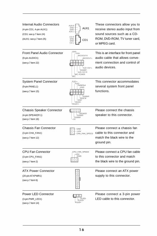
Internal Audio Connectors These connectors allow you to
(4-pin CD1, 4-pin AUX1) receive stereo audio input from
(CD1: see p.7 item 24) sound sources such as a CD-
(AUX1: see p.7 item 25) ROM, DVD-ROM, TV tuner card,
or MPEG card.
Front Panel Audio Connector This is an interface for front panel
(9-pin AUDIO1) audio cable that allows conve-
(see p.7 item 22) nient connection and control of
audio devices.
System Panel Connector This connector accommodates
(9-pin PANEL1) several system front panel
(see p.7 item 15) functions.
Chassis Speaker Connector Please connect the chassis
(4-pin SPEAKER 1) speaker to this connector.(see p.7 item 16)
Chassis Fan Connector Please connect a chassis fan
(3-pin CHA_FAN1) cable to this connector and
(see p.7 item 12) match the black wire to the
ground pin.
CPU Fan Connector Please connect a CPU fan cable
(3-pin CPU_FAN1) to this connector and match
(see p.7 item 2) the black wire to the ground pin.
ATX Power Connector Please connect an ATX power
(20-pin ATXPWR1) supply to this connector.(see p.7 item 6)
Power LED Connector Please connect a 3-pin power
(3-pin PWR_LED1) LED cable to this connector.(see p.7 item 14)
+5V
DUMMYDUMMY
SPEAKER
1
GND
DUMMY
+5VA
BACKOUT-R
BACKOUT-L
AUD-OUT-L
AUD-OUT-R
MIC-POWERMIC
1
GND
PWRBTN#PLED-
PLED+
DUMMYRESET#
GND
HDLED+HDLED-
1
GND
+12V
CHA_FAN_SPEED
CPU_FAN_SPEED
GND+12V
1
PLED+PLED+
PLED-
CD-R
GNDGND
CD-L
AUX-R
GNDGND
AUX-L
CD1
AUX1

17
3. BIOS Setup
3.1 BIOS Setup Utility
This section explains how to use the BIOS Setup Utility to configure your system.
The Flash Memory on the motherboard stores the BIOS Setup Utility. You may run the
BIOS Setup when you start up the computer. Please press <F2> during the Power-
On-Self-Test (POST) to enter the BIOS Setup Utility, otherwise, POST will continue
with its test routines.
If you wish to enter the BIOS Setup after POST, restart the system by pressing
<Ctl> + <Alt> + <Delete>, or by pressing the reset button on the system chassis.
You may also restart the system by turning the system off and then back on.
The BIOS Setup Utility is designed to be user-friendly. It is a menu-driven program,
which allows you to scroll through its various sub-menus and select among the
predetermined choices.
Because the BIOS software is constantly being updated, the
following BIOS setup screens and descriptions are for reference
purpose only, and may not exactly match what you see on your
screen.
3.1.1 BIOS Menu Bar
The top of the screen has a menu bar with the following selections:
MAIN Sets up the basic system configuration
ADVANCED Sets up the advanced features
SECURITY Sets up the security features
POWER Configures Power Management features
BOOT Configures the default system device that is used
to locate and load the Operating System
EXIT Exits the current menu or the BIOS Setup
To access the menu bar items, press the right or left arrow key on the keyboard
until the desired item is highlighted.
3.1.2 Legend Bar
At the bottom of the Setup Screen is a legend bar. The following table lists the keys
in the legend bar with their corresponding functions.

18
Navigation Key(s) Function Description
<F1> Displays the General Help Screen
<ESC> Jumps to the Exit menu or returns to the upper menu
from the current menu
/ Moves cursor up or down between fields
/ Selects menu to the left or right
+ / - Increases or decreases values
<Enter> Brings up a selected menu for a highlighted field
<F9> Loads all the setup items to default value
<F10> Saves changes and exits Setup
3.2 Main Menu
When you enter the BIOS Setup Utility, the following screen appears.
System Date [Month/Day/Year]
Set the system date that you specify. Valid values for month, day, and year are
Month: (Jan to Dec), Day: (1 to 31), Year: (up to 2099). Use keys to move
between the Month, Day, and Year fields.
System Time [Hour:Minute:Second]
Set the system to the time that you specify. Use keys to move between
the Hour, Minute, and Second fields.
Floppy Drives
Use this to set the type of floppy drives installed.
IDE Devices
Use this to configure IDE devices.
AMIBIOS SETUP UTILITY - VERSION 3.31a
Main Advanced Security Power Boot Exit
System DateSystem Time
Floppy DrivesIDE Devices
BIOS VersionProcessor TypeProcessor SpeedL1 Cache SizeL2 Cache SizeTotal Memory
DDR1DDR2
[ Setup Help ]
K7VT4A+ BIOS P1.00AMD Athlon(tm) XP 2600+
Month: Jan - DecDay: 01 - 31
Year: 1980 - 2099
F1:HelpEsc:Exit
F9:Setup DefaultsF10:Save & Exit
+/-:Change Values
Enter:Select Sub-Menu
:Select Item:Select Menu
2133 MHz128 KB
256 KB512 MB
None512 MB / 200 MHz (DDR400)
20:07:4031 2003 FriOct

19
AMIBIOS SETUP UTILITY - VERSION 3.31a
Main
TypeCylindersHeadsWrite PrecompensationSectorsMaximum CapacityLBA ModeBlock ModeFast Programmed I/O Modes32 Bit Transfer ModeUltra DMA Mode
[ Setup Help ]
F1:HelpEsc:Previous Menu
F9:Setup DefaultsF10:Save & Exit
+/-:Change Values
Enter:Select Sub-Menu
:Select Item
Primary IDE Master
OffOffAutoOffAuto
Select how to set theparameters of drive,
OrSelect [AUTO] to setall HDD parametersautomatically.
Auto
TYPE
To set the type of the IDE device, first, please select “IDE Devices” on Main
menu and press <Enter> to get into the sub-menu. Then, select among
“Primary IDE Master”, “Primary IDE Slave”, “Secondary IDE Master”, and
“Secondary IDE Slave” to make configuration of its type. Below are the
configuration options.
[USER]: It allows user to manually enter the number of cylinders, heads,
and sectors per track for the drive.
Before attempting to configure a hard disk drive, make sure you
have the correct configuration information supplied by the drive
manufacturer. Incorrect settings may cause the system to fail
to recognize the installed hard disk.
[Auto]: Select [Auto] to automatically detect hard disk drive. If auto-
detection is successful, the BIOS Setup automatically fills in the
correct values for the remaining fields on this sub-menu. If the auto-
detection fails, it may due to that the hard disk is too old or too new.
If the hard disk was already formatted on an older system, the BIOS
Setup may detect incorrect parameters. In these cases, select [User]
to manually enter the IDE hard disk drive parameters.
After entering the hard disk information into BIOS, use a disk utility,
such as FDISK, to partition and format the new IDE hard disk
drives. This is necessary so that you can write the data into or
read the data from the installed hard disk. Please make sure to set
the partition of the Primary IDE hard disk drives to make them
active.

20
[CD/DVD]: This is used for IDE CD/DVD drives.
[ARMD]: This is used for IDE ARMD (ATAPI Removable Media Device),
such as MO.
Cylinders
This is used to configure the number of cylinders. Refer to the drive
documentation to determine the correct value.
Heads
This is used to configure the number of read/write heads. Refer to the
drive documentation to determine the correct values.
Write Pre-compensation
Enter Write Pre-compensation sector. Refer to the drive documentation to
determine the correct value.
Sectors
This is used to configure the number of sectors per track. Refer to the
drive documentation to determine the correct value.
Maximum Capacity
This field shows the drive’s maximum capacity as calculated by the BIOS
based on the drive information you entered.
LBA Mode
This allows user to select the LBA mode for a hard disk > 512 MB under
DOS and Windows; for Netware and UNIX user, select [Off] to disable the
LBA mode.
Block Mode
Set the block mode to [On] will enhance hard disk performance by reading
or writing more data during each transfer.
Fast Programmed I/O Modes
This allows user to set the PIO mode to enhance hard disk performance by
optimizing the hard disk timing.
32 Bit Transfer Mode
It allows user to enable 32-bit access to maximize the IDE hard disk data
transfer rate.
Ultra DMA Mode
Ultra DMA capability allows improved transfer speeds and data integrity
for compatible IDE devices. Set to [Disabled] to suppress Ultra DMA
capability.
3.3 Advanced, Security, Power, Boot, and Exit Menus
Detailed descriptions of these menus are listed in the Appendix. See page 22.

21
4. Software Support
4.1 Install Operating System
This motherboard supports various Microsoft® Windows® operating systems:
98 SE / ME / 2000 / XP. Because motherboard settings and hardware options vary,
use the setup procedures in this chapter for general reference only. Refer to your
OS documentation for more information.
4.2 Support CD Information
The Support CD that came with the motherboard contains necessary drivers and
useful utilities that will enhance the motherboard features.
4.2.1 Running The Support CD
To begin using the support CD, insert the CD into your CD-ROM drive. The CD
automatically displays the Main Menu if “AUTORUN” is enabled in your computer.
If the Main Menu did not appear automatically, locate and double click on the file
ASSETUP.EXE from the BIN folder in the Support CD to display the menus.
4.2.2 Drivers Menu
The Drivers Menu shows the available devices drivers if the system detects
installed devices. Install the necessary drivers to activate the devices.
4.2.3 Utilities Menu
The Utilities Menu shows the applications software that the motherboard
supports. Click on a specific item then follow the installation wizard to install it.
4.2.4 ASRock PC-DIY Live Demo Program
ASRock presents you a multimedia PC-DIY live demo, which shows you how to
install your own PC system step by step. You may find the file through the
following path:
..\ MPEGAV \ AVSEQ01.DAT
To see this demo program, you may run Microsoft® Media Player® to play the file.
4.2.5 Contact Information
If you need to contact ASRock or want to know more about ASRock, welcome
to visit ASRock’s website at http://www.asrock.com; or you may contact your
dealer for further information.

22
Appendix: Advanced BIOS SetupThis section will introduce you the following BIOS Setup menus: “Advanced,”
“Security,” “Power,” “Boot,” and “Exit.”
1. Advanced BIOS Setup Menu
Spread Spectrum
This field should always be [Disabled] for better system stability.
CPU Host Frequency
[Auto]
It is recommended to select this option, which will let the CPU host frequency of
this motherboard determined by the jumper-setting.
[Manual]
This allows user to set CPU host frequency manually. However, because the
CPU host frequency of this motherboard is determined by the jumper-setting,
you must set the FSB jumper adjustment according to your AMD CPU before you
use this “Manual” option as the FSB setting in BIOS setup to perform over
clocking. This is not recommended unless you thoroughly know the feature.
Wrong setup may cause problems during operation.
DRAM Frequency
If set to [Auto], the motherboard will detect the inserted memory module(s) and
automatically assign appropriate frequency. You may select other value as
operating frequency: [133MHz (DDR266)], [166MHz (DDR333)],
[200MHz (DDR400)].
Flexibility Option
The default value of this option is [Disabled]. It will allow better tolerance for
memory compatibility when it is set to [Enabled].
AMIBIOS SETUP UTILITY - VERSION 3.31a
Main Advanced Security Power Boot Exit
Spread Spectrum
ConfigurationConfiguration
CPU Host FrequencyActual Frequency
DRAM FrequencyFlexibility Option
Chipset ConfigurationResourcePeripheralSystem Hardware Monitor
[ Setup Help ]
Auto133MHzAutoDisabled
<Enter> to enable ordisable the feature ofspread spectrum.
F1:HelpEsc:Exit
F9:Setup DefaultsF10:Save & Exit
+/-:Change Values
Enter:Select Sub-Menu
:Select Item:Select Menu
Disabled
23
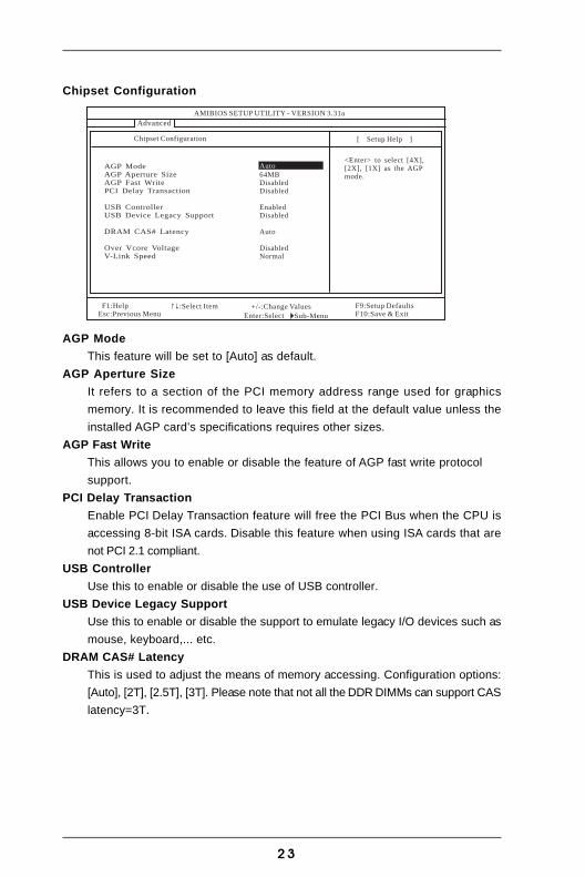
Chipset Configuration
AGP Mode
This feature will be set to [Auto] as default.
AGP Aperture Size
It refers to a section of the PCI memory address range used for graphics
memory. It is recommended to leave this field at the default value unless the
installed AGP card’s specifications requires other sizes.
AGP Fast Write
This allows you to enable or disable the feature of AGP fast write protocol
support.
PCI Delay Transaction
Enable PCI Delay Transaction feature will free the PCI Bus when the CPU is
accessing 8-bit ISA cards. Disable this feature when using ISA cards that are
not PCI 2.1 compliant.
USB Controller
Use this to enable or disable the use of USB controller.
USB Device Legacy Support
Use this to enable or disable the support to emulate legacy I/O devices such as
mouse, keyboard,... etc.
DRAM CAS# Latency
This is used to adjust the means of memory accessing. Configuration options:
[Auto], [2T], [2.5T], [3T]. Please note that not all the DDR DIMMs can support CAS
latency=3T.
AMIBIOS SETUP UTILITY - VERSION 3.31a
Advanced
AGP ModeAGP Aperture SizeAGP Fast WritePCI Delay Transaction
USB ControllerUSB Device Legacy Support
DRAM CAS# Latency
Over Vcore VoltageV-Link Speed
[ Setup Help ]
F1:HelpEsc:Previous Menu
F9:Setup DefaultsF10:Save & Exit
+/-:Change Values
Enter:Select Sub-Menu
:Select Item
Chipset Configuration
64MBDisabledDisabled
EnabledDisabled
Auto
DisabledNormal
<Enter> to select [4X],[2X], [1X] as the AGPmode.
Auto

24
Over Vcore Voltage
This feature allows you to increase the CPU Vcore voltage with two levels. The
default value is [Disabled].
It is not recommended to enable “Over Vcore Voltage” feature. Doing so
may cause CPU damage.
V-Link Speed
This feature allows you to speed up the V-Link speed. The default value is
[Normal].
Resource Configuration
PCI Latency Timer (PCI Clocks)
The default is 32. It is recommended to keep the default value unless the in-
stalled PCI expansion cards’ specifications require other settings.
Primary Graphics Adapter
Select PCI or AGP as the primary graphics adapter.
AMIBIOS SETUP UTILITY - VERSION 3.31a
Advanced
PCI Latency Timer (PCI Clocks)Primary Graphics Adapter
[ Setup Help ]
F1:HelpEsc:Previous Menu
F9:Setup DefaultsF10:Save & Exit
+/-:Change Values
Enter:Select Sub-Menu
:Select Item
Resource Configuration
PCI32
<Enter> to select PCIclocks. Leave ondefault setting for thebest PCI performance.

25
Peripheral Configuration
OnBoard FDC
Use this to enable or disable floppy drive controller.
OnBoard Serial Port
Use this to set addresses for the onboard serial ports or disable serial ports.
Configuration options: [Auto], [Disabled], [3F8 / IRQ4 / COM1],
[2F8 / IRQ3 / COM2], [3E8 / IRQ4 / COM3], [2E8 / IRQ3 / COM4].
OnBoard Infrared Port
You may select [Auto] or [Disabled] for this onboard infrared port feature.
OnBoard Parallel Port
Select Parallel Port address or disable Parallel Port. Configuration options: [Auto],
[Disabled], [378], [278].
Parallel Port Mode
Set the operation mode of the parallel port. The default value is [ECP+EPP]. If
this option is set to [ECP+EPP], it will show the EPP version in the following
item, “EPP Version”.
OnBoard Midi Port
Select address for Midi Port or disable Midi Port. Configuration options: [Disabled],
[330], [300], [290], [292].
Midi IRQ Select
Use this to select Midi IRQ. Configuration options: [3], [4], [5], [7], [10], [11].
OnBoard Game Port
Select address for Game Port or disable Game Port. Configuration options:
[Disabled], [200h], [208h].
AMIBIOS SETUP UTILITY - VERSION 3.31a
Advanced
OnBoard FDCOnBoard Serial PortOnBoard Infrared PortOnBoard Parallel Port
Parallel Port ModeEPP VersionParallel Port IRQParallel Port DMA Channel
OnBoard Midi PortMidi IRQ Select
OnBoard Game PortOnBoard IDEOnBoard LANOnBoard AC' 97 Audio
[ Setup Help ]
F1:HelpEsc:Previous Menu
F9:Setup DefaultsF10:Save & Exit
+/-:Change Values
Enter:Select Sub-Menu
:Select Item
Peripheral Configuration
AutoDisabledAutoECP+EPP1.9AutoAutoDisabled5200hBothEnabledAuto
Auto
<Enter> to enable ordisable the floppydrive controller.
26
OnBoard IDE
You may enable either the primary IDE channel or the secondary IDE channel. Or
you may enable both the primary and the secondary IDE channels by selecting
[Both]. Set to [Disabled] will disable the both. Configuration options: [Disabled],
[Primary], [Secondary], [Both].
OnBoard LAN
This allows you to enable or disable the onboard LAN feature.
OnBoard AC’97 Audio
Select [Disabled], [Auto] or [Enabled] for the onboard AC’97 Audio feature.
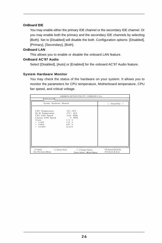
System Hardware Monitor
You may check the status of the hardware on your system. It allows you to
monitor the parameters for CPU temperature, Motherboard temperature, CPU
fan speed, and critical voltage.
AMIBIOS SETUP UTILITY - VERSION 3.31a
Advanced
CPU TemperatureM / BCPU FAN SpeedChassisVcore+ 3.30V+ 5.00V
Temperature
FAN Speed
+ 12.00V
[ Setup Help ]
F1:HelpEsc:Previous Menu
F9:Setup DefaultsF10:Save & Exit
+/-:Change Values
Enter:Select Sub-Menu
:Select Item
System Hardware Monitor
35 C / 95 F27 C / 82 F3110 RPM
0 RPM1.72 V3.31 V4.97 V12.16 V

27
2. Security Setup Menu
Supervisor Password: This field shows the status of the Supervisor Password.
[Clear]: No password has been set.
[Set]: Supervisor password has been set.
User Password: This field shows the status of the User Password.
[Clear]: No password has been set.
[Set]: User password has been set.
Set Supervisor Password: Press <Enter> to set the Supervisor Password. Valid
password can be a 1 to 6 alphanumeric characters combination. If you already
have a password, you need to enter your current password first in order to
create a new password.
Set User Password: Press <Enter> to set the User Password. Valid password can
be a 1 to 6 alphanumeric characters combination. If you already have a
password, you need to enter your current password first in order to create a
new password.
Password Check: Select the check point for “Password Check”. Configuration
options: [Setup], [Always]. If [Setup] option is selected, the “Password Check”
is performed before BIOS setup. If [Always] option is selected, the “Password
Check” is performed before both boot-up and BIOS setup.
AMIBIOS SETUP UTILITY - VERSION 3.31a
Main Advanced Security Power Boot Exit
Supervisor PasswordUser Password
Set Supervisor PasswordSet User Password
Password Check
[ Setup Help ]ClearClear <Enter> to set the
supervisor password.
F1:HelpEsc:Exit
F9:Setup DefaultsF10:Save & Exit
+/-:Change Values
Enter:Select Sub-Menu
:Select Item:Select Menu
[ Enter ]
Setup
[ Enter ]

28
3. Power Setup Menu
Suspend to RAM
This field allows you to select whether to auto-detect or disable the Suspend-
to-RAM feature. Select [Auto] will enable this feature if the system supports it.
Repost Video on STR Resume
This feature allows you to repost video on STR resume. It is recommended to
enable this feature under Microsoft® Windows® 98 / ME.
Restore on AC/Power Loss
This allows you to set the power state after an unexpected AC/power loss. If
[Power Off] is selected, the AC/power remains off when the power recovers.
If [Power On] is selected, the AC/power resumes and the system starts to boot
up when the power recovers.
Ring-In Power On
Use this to enable or disable Ring-in signals to turn on the system from the
power-soft-off mode.
PCI Devices Power On
Use this to enable or disable PCI devices to turn on the system from the power-
soft-off mode.
PS/2 Keyboard Power On
Use this to enable or disable PS/2 keyboard to turn on the system from the
power-soft-off mode.
RTC Alarm Power On
Use this to enable or disable RTC (Real Time Clock) to power on the system. If
[Enable] is selected, you must fill the RTC Alarm Date / Hour / Minute / Second
sub-fields with the actual wake up time you desire.
AMIBIOS SETUP UTILITY - VERSION 3.31a
Main Advanced Security Power Boot Exit
Suspend To RAMRepost Video on STR ResumeRestore on AC / Power LossRing-In Power OnPCI Devices Power OnPS / 2 Keyboard Power OnRTC Alarm Power On
RTC Alarm DateRTC Alarm HourRTC Alarm MinuteRTC Alarm Second
[ Setup Help ]
F1:HelpEsc:Exit
F9:Setup DefaultsF10:Save & Exit
+/-:Change Values
Enter:Select Sub-Menu
:Select Item:Select Menu
DisabledDisabledPower OffDisabledDisabledDisabledDisabledEvery Day123030
<Enter> to selectauto-detect or disablethe Suspend-to-RAMfeature.

29
4. Boot Setup Menu
Quick Boot Mode
Enable this mode will speed up the boot-up routine by skipping memory retestings.
Boot Up Num-Lock
If this is enabled, it will automatically activate the Numeric Lock function after
boot-up.
Boot To OS/2
This enables boot-up to OS/2 operating system.
Boot From Network
Use this to enable or disable “boot from network” feature.
Boot Device Priority
This allows you to set the boot device priority.
AMIBIOS SETUP UTILITY - VERSION 3.31a
Main Advanced Security Power Boot Exit
Quick Boot ModeBoot Up Num-LockBoot To OS/2Boot From Network
Boot Device Priority
[ Setup Help ]
OnNoDisabled
<Enter> to enable ordisable the quick bootmode.
F1:HelpEsc:Exit
F9:Setup DefaultsF10:Save & Exit
+/-:Change Values
Enter:Select Sub-Menu
:Select Item:Select Menu
Enabled

30
AMIBIOS SETUP UTILITY - VERSION 3.31a
Main Advanced Security Power Boot Exit
Exit Saving ChangesExit Discarding ChangesLoad Default SettingsDiscard Changes
[ Setup Help ]
Exits and saves thechanges in CMOS RAM.
F1:HelpEsc:Exit
F9:Setup DefaultsF10:Save & Exit
+/-:Change Values
Enter:Select Sub-Menu
:Select Item:Select Menu
[ Enter ][ Enter ][ Enter ]
[ Enter ]
5. Exit Menu
Exit Saving Changes
After you enter the sub-menu, the message “Save current settings and exit” will
appear. If you press <ENTER>, it will save the current settings and exit the BIOS
SETUP Utility.
Exit Discarding Changes
After you enter the submenu, the message “Quit without saving changes” will
appear. If you press <ENTER>, you will exit the BIOS Setup Utility without making
any changes to the settings.
Load Default Settings
After you enter the submenu, the message “Load default settings” will appear.
If you press <Enter>, it will load the default values for all the setup configuration.
Discard Changes
After you enter the sub-menu, the message “Load setup original values” will
appear. If you press <ENTER>, original values will be restored and all changes
are discarded.

1
RAID Software
1. BeginnDie “RAID Software” ist ein auf Windows basierendes Programm mit
einer grafischen Benutzerschnittstelle und bietet Ihnen ein leicht zu
bedienendes Werkzeug zum Konfigurieren und Verwalten der
Festplatten oder Disk-Arrays, die mit dem VT8237 SATA-Controller
verbunden sind, an.
Nachdem die GUI-Software installiert wurde, wird die Software immer
mit dem Starten Ihres Windows-Betriebssystems automatisch
ausgeführt. Ein -Symbol in der Taskleiste zeigt an, dass die GUI-
Software momentan arbeitet.
Klicken Sie doppelt auf das Symbol, um die Hauptbenutzerschnittstelle
dieser Software aufzurufen.

2
2. Erstellen eines Disk-Arrays1. Sie können auf eine der drei Tasten klicken, um verschiedene
Typen von Disk-Arrays – RAID 1, Span und RAID 0
zu erstellen. Daraufhin erscheint ein „Select Array Creating
Method“ (Arrayerstellungsmethode wählen)-Fenster.
Auto:
Die Software richtet ein Disk-Array aus den verfügbaren
Festplatten ein. Sie können später die Festplatten modifizieren. Es
ist sehr ratsam, diese Methode zu verwenden.
Custom (Benutzer):
Sie richten ein Disk-Array manuell ein.

3
2. Klicken Sie auf die „Auto“-Schaltfläche: Das „Creating Array“
(Array erstellen)-Fenster erscheint daraufhin.
Haben Sie „Custom“ (Benutzer) gewählt, dann werden die
verfügbaren Festplatten zur Einrichtung eines Arrays in dem
„Available Disks“ (Verfügbare Disks)-Fenster aufgelistet. Wählen
Sie ein Festplatte und klicken dann mit der rechten Taste darauf,
um diese Festplatte dem Array hinzuzufügen. Sie können
ebenfalls eine gewählte Festplatte von dem Array entfernen.
Klicken Sie auf die Festplatte im „Array Disks“-Fenster und dann
auf die Linkspfeil-Schaltfläche, um die gewählte Festplatte zu
entfernen.
Klicken Sie zum Erstellen des Arrays auf die „Create“
(Erstellen)-Schaltfläche oder zum Abbrechen auf „Cancel“
(Abbrechen).
Ein Warnhinweis wird angezeigt, wenn die „Create“
(Erstellen)-Schaltfläche gedrückt wird.
Klicken Sie zum fertig Stellen der Erstellung des Disk-Arrays auf
„Yes“ (Ja) oder zum Abbrechen auf „No“ (Nein).
4
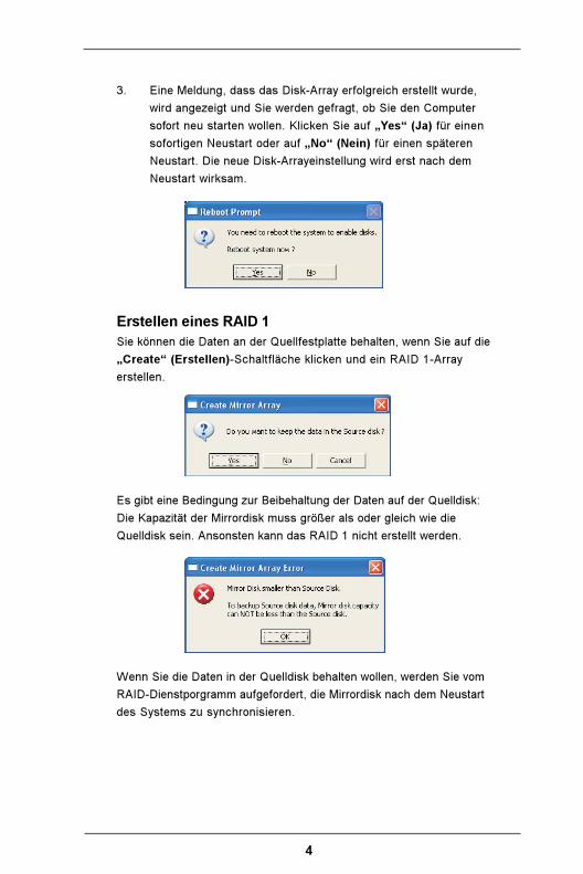
3. Eine Meldung, dass das Disk-Array erfolgreich erstellt wurde,
wird angezeigt und Sie werden gefragt, ob Sie den Computer
sofort neu starten wollen. Klicken Sie auf „Yes“ (Ja) für einen
sofortigen Neustart oder auf „No“ (Nein) für einen späteren
Neustart. Die neue Disk-Arrayeinstellung wird erst nach dem
Neustart wirksam.
Erstellen eines RAID 1
Sie können die Daten an der Quellfestplatte behalten, wenn Sie auf die
„Create“ (Erstellen)-Schaltfläche klicken und ein RAID 1-Array
erstellen.
Es gibt eine Bedingung zur Beibehaltung der Daten auf der Quelldisk:
Die Kapazität der Mirrordisk muss größer als oder gleich wie die
Quelldisk sein. Ansonsten kann das RAID 1 nicht erstellt werden.
Wenn Sie die Daten in der Quelldisk behalten wollen, werden Sie vom
RAID-Dienstporgramm aufgefordert, die Mirrordisk nach dem Neustart
des Systems zu synchronisieren.

5
Erstellen eines JBOD
Die Daten auf der ersten Festplatte des JBOD-Arrays können beim
Erstellen des JBOD-Arrays beibehalten werden.
Die Daten in der ersten Festplatte werden beibehalten, während die
anderen Festplatten des JBOD hinter der ersten Festplatte erweitert
und unbelegt gemacht werden.

6
3. Löschen eines Disk-Arrays
1. Wählen Sie das zu löschende Disk-Array aus dem linken Feld.
Klicken Sie auf das „Remove Array“ (Array entfernen)-
Symbol . Ein Warnhinweis erscheint daraufhin.
2. Klicken Sie zum Löschen des gewählten Disk-Arrays auf „Yes“
(Ja) oder zum Abbrechen auf „No“ (Nein).

7
3. Eine Meldung, dass das Disk-Array erfolgreich entfernt wurde,
wird angezeigt und Sie werden gefragt, ob Sie den Computer
sofort neu starten wollen. Klicken Sie auf „Yes“ (Ja) für einen
sofortigen Neustart oder auf „No“ (Nein) für einen späteren
Neustart. Die neue Einstellung wird erst nach dem Neustart
wirksam.
Warnung:
Außer beim RAID 1 werden alle Daten auf dem Disk-Array durch Löschen des
Disk-Arrays gelöscht. Wenn Sie ein RAID 1 löschen, werden die Daten auf den
beiden Festplatten beibehalten.
4. Prüfen aller FestplattenSie können prüfen, ob alle Festplatten richtig funktionieren, indem Sie
auf das Symbol klicken. Nach der Prüfung erscheint ein Fenster, in
dem der aktuelle Status jeder Festplatte angezeigt wird.
Ihre Festplatte muss mit den ATA/ATAPI-5 Spezifikationen konform sein
und die SMART-Befehle unterstützen. Ansonsten schlägt die Prüfung
fehl.

8
5. Überprüfen der MirrordiskDie Daten auf der Mirrordisk müssen mit den auf der entsprechenden
Quelldisk übereinstimmen, um die Fehlertoleranz für RAID 1 anzubieten.
1. Wählen Sie ein RAID 1. Klicken Sie mit der rechten Maustaste auf
das gewählte RAID. Ein Verknüpfungsmenü erscheint daraufhin.
Klicken Sie auf „Verify Mirror“ (Mirror überprüfen), um zu
überprüfen, ob die Inhalte der Quellen- und Mirrordisk identisch
sind.

9
2. Ein Dialogfenster zeigt den Überprüfungsprozess an, wenn die
„Verify Mirror“ (Mirror überprüfen)-Funktion aktiviert wird.
Sie können diesen Prozess zu jeder Zeit anhalten oder
abbrechen. Dieser Prozess kann lange dauern, wenn die RAID-
Kapazität groß ist.
3. Wenn der Inhalt der Mirrordisk mit dem Inhalt der entsprechenden
Quelldisk nicht übereinstimmt, wird die Mirrordisk mit einem „need-
sync“(Sync. Nötig)-Symbol markiert . Eine „need-sync“
(Sync. Nötig)-Mirrordisk sollte so schnell wie möglich
synchronisiert werden.

10
6. Synchronisieren der MirrordiskBei einem RAID 1 muss das Array synchronisiert werden, wenn die
Daten auf der Mirrordisk mit den Daten auf der entsprechenden
Quelldisk nicht übereinstimmen. Manchmal können die Daten auf der
Mirrordisk neuer als die auf der Quelldisk sein. Das kann passieren,
wenn die Quelldisk z.B. abwesend ist und die Mirrordisk im
Toleranzmodus arbeitet. Deshalb heißt „Synchronize Mirror“(Mirror
synchronisieren), dass die Daten der Quelldisk und Mirrordisk identisch
gemacht werden. Die RAID Software markiert die Mirrordisk immer mit
einem „need-sync“ (Sync. Nötig)-Symbol , selbst wenn die
Mirrordisk die richtigen Daten enthält.
1. Wählen Sie das RAID 1. Klicken Sie mit der rechten Maustaste auf
das gewählte RAID. Ein Verknüpfungsmenü erscheint daraufhin.
Klicken Sie auf Synchronize Mirror (Mirror
synchronisieren), um die Quelldisk und Mirrordisk zu
synchronisieren.

11
2. Ein Dialogfenster zeigt den Prozess an, wenn die
Synchronisation beginnt. Sie können diesen Prozess zu jeder Zeit
anhalten oder abbrechen.
3. Eine Meldung erscheint, wenn die Synchronisation fertig ist.
7. DiskfehlererkennungDie RAID Software gibt eine Fehlermeldung ab, wenn Fehler oder die
Abwesenheit einer Festplatte erkannt wurde.

12
8. Duplizieren des kritischen RAID 1-ArraysWenn die Software während des Startens des Systems Inkonsistenzen
zwischen der Quelldisk und Mirrordisk des RAID 1 erkennt, wird das
Disk-Array als kritisch markiert und Sie werden aufgefordert, das RAID
1 zu duplizieren, um die Mirrordisk mit der entsprechenden Quelldisk
übereinstimmend zu machen.
Klicken Sie auf „Yes“ (Ja) für eine sofortige Synchronisation oder auf
„No“ (Nein) für eine spätere Synchronisation.
Ein Dialogfenster zeigt den Prozess an, wenn die Synchronisation
beginnt. Sie können diesen Prozess zu jeder Zeit anhalten oder
abbrechen. Das RAID bleibt im „need-sync“ (Sync. Nötig) -Zustand,
wenn der Synchronisationsprozess abgebrochen wurde. In diesem Fall
sollten Sie die Synchronisation noch einmal ausführen, um identische
Daten in der Quelldisk und Mirrordisk zu garantieren.
Eine Meldung erscheint, wenn die Synchronisation fertig ist.

13
9. Umbau eines fehlerhaften RAID 1-ArraysWenn Fehler oder die Abwesenheit einer Festplatte des RAIDs
während des Startens des Systems erkannt wurden, wird das Array
als fehlerhaft markiert.
Wenn die RAID Software ein fehlerhaftes RAID 1-Array erkennt, leitet
sie eine Reihen von Schritten für eine Reparatur ein.
1. Eine Meldung, dass das RAID fehlerhaft ist, wird angezeigt.
Klicken Sie auf Yes (Ja).
2. Danach erscheint ein anderes Dialogfenster. Wenn der Fehler
bloß daran liegt, dass die Quelldisk oder Mirrordisk nicht
angeschlossen ist, dann klicken Sie bitte zum Abbrechen des
Umbaus auf „Cancel“ (Abbrechen). Schalten Sie das System
aus. Schließen Sie die abwesende Festplatte an und starten
dann das System neu. Wenn die originale Festplatte defekt ist,
können Sie eine neue Festplatte anschließen und dann das
System neu starten. Klicken Sie auf „Next“(Weiter), um zum
nächsten Schritt fortzufahren.

14
3. Wählen Sie eine Festplatte von „Available Disks“ (Verfügbare
Disks) und klicken dann auf die Schaltfläche , um die
defekte Festplatte zu ersetzen. Klicken Sie anschließend auf
„Next“(Weiter).

15
4. Ein Warnhinweis wird angezeigt. Klicken Sie auf „Next“
(Weiter), wenn Sie das RAID mit der im vorherigen Schritt
gewählten Festplatte umbauen möchten.
Warnung:
Die Daten auf der gewählten Festplatte werden gelöscht.
5. Starten Sie das System neu.
6. Dieses RAID wird als kritisches RAID markiert. Die RAID Software
wird den „Duplicating Critical RAID 1“ (Kritisches RAID 1
duplizieren)-Prozess ausführen.

1
Anleitung zur Installation von SATA-
Festplatten und zur RAID-Konfiguration
1. Anleitung für Installation von TA-Festplatten ................... 2
1.1 Serial ATA- (SATA-) Festplatteninstallation ............. 2
1.2 SATA HDD-Treiberdiskette erstellen ...................... 3
2. Anleitung zur RAID-Konfiguration .................................... 4
2.1 Einführung in RAID ................................................. 4
2.2 Vorkehrungen vor AID-Konfiguration ...................... 6
2.3 BIOS-Konfigurationsprogramm ............................. 7
2.3.1 Aufrufen des
BIOS-Konfigurationsprogramms ............. 7
2.3.2 Erstellen eines Disk-Arrays ...................... 8
2.3.3 Löschen eines Disk-Arrays .................... 13
2.3.4 Wählen des Boot-Arrays ......................... 14
3. Windows 2000 / Windows XP installieren .................... 15

2
1. Anleitung für Installation von SATA-Festplatten
1.1 Serial ATA- (SATA-) Festplatteninstallation
Dieses Mainboard arbeitet mit dem VIA VT8237 Southbridge-
Chipsatz, der Serial ATA- (SATA-) Festplatten unterstützt. Als
lokale Datenspeichergeräte können Sie SATA-Laufwerke an
dieses Mainboard anschließen. Dieser Abschnitt zeigt Ihnen, wie
Sie die SATA-Festplatten installieren.
SCHRITT 1: Installieren Sie die SATA-Festplatten in den
Laufwerkseinschüben des Gehäuses.
SCHRITT 2: Verbinden Sie das SATA-Netzkabel mit der SATA-
Festplatte.
SCHRITT 3: Schließen Sie ein Ende des SATA-Datenkabels am
SATA-Anschluss des Motherboards an.
SCHRITT 4: Schließen Sie das andere Ende des SATA-
Datenkabels an die SATA-Festplatte an.

3
1.2 SATA HDD-Treiberdiskette erstellen
Wenn Sie Windows 2000 oder Windows XP auf den SATA-
Festplatten installieren möchten, benötigen Sie eine SATA-
Treiberdiskette, bevor Sie mit der Installation des Betriebssystems
beginnen.
SCHRITT 1: Legen Sie die ASRock Support-CD in Ihr optisches
Laufwerk, um Ihr System hochzufahren. (Legen
Sie zu diesem Zeitpunkt KEINE Diskette in das
Diskettenlaufwerk ein!)
SCHRITT 2: Während des Selbsttests zu Beginn des
Systemstarts drücken Sie die <F11>-Taste – ein
Fenster zur Auswahl des Boot-Laufwerkes
(Startlaufwerk) erscheint. Bitte wählen Sie das CD-
ROM-Laufwerk als Boot-Laufwerk.
SCHRITT 3: Die Meldung „Do you want to generate Serial ATA
driver diskette [Y/N]?“ [Serial ATA-Treiberdiskette
erstellen [Y/N]?] bestätigen Sie mit <Y>.
SCHRITT 4: Daraufhin werden die Meldungen
Please insert a diskette into the floppy drive.
WARNING! Formatting the floppy diskette will
lose ALL data in it!
Start to format and copy files [Y/N]?
[Bitte legen Sie eine Diskette in das
Diskettenlaufwerk ein. WARNUNG! Das
Formatieren der Diskette löscht ALLE darauf
enthaltenen Daten!
Formatieren und Kopieren der Dateien starten
[Y/N]?]
angezeigt. Legen Sie bitte eine Diskette in das
Diskettenlaufwerk ein und drücken Sie <Y>.
SCHRITT 5: Das System beginnt mit dem Formatieren der
Diskette und kopiert die SATA-Treiber auf die
Diskette.
Sobald die SATA-Treiberdiskette bereit ist, können Sie direkt mit der Installation von
Windows 2000 / Windows XP beginnen, ohne die RAID-Konfiguration in Ihrem
System einzurichten – oder Sie können das “VT8237 SATA RAID BIOS” verwenden,
um die RAID 0 / RAID 1 / JBOD -Konfiguration vor der Installation des
Betriebssystems durchzuführen. Sie können die RAID-Konfiguration auch mit “VIA
RAID Tool” in einer Windows-Umgebung einstellen. Beziehen Sie sich auf das
Dokument “Anleitung für VIA RAID Tool” auf der Support-CD, das sich im Ordner
des folgendes Pfades befindet: .. \ VIA RAID Tool

4
2. Anleitung zur RAID-Konfiguration
2.1 Einführung in RAID
Dieses Motherboard bedient sich des VIA VT8237 South Bridge-
Chipsatzes, in dem der RAID-Controller integriert ist, der die RAID
0- / RAID 1- / JBOD-Funktion mit zwei unabhängigen Serial ATA-
(SATA) Kanälen unterstützt. Dieser Abschnitt stellt Ihnen die
grundlegenden Kenntnisse von RAID vor und führt Sie durch die
Konfiguration der RAID 0-, RAID 1- und JBOD-Einstellungen.
RAID
Der Ausdruck „RAID“ steht für „Redundant Array of Independable
Disks“ (Redundante Gruppe unabhängiger Laufwerke“ und ist
eine Methode zur Kombination von zwei oder mehreren
Festplatten zu einer logischen Einheit. Um optimale Leistung zu
erzielen, installieren Sie bitte Laufwerke gleichen Modells und
gleicher Kapazität, wenn Sie einen RAID-Satz erstellen.
RAID 0 (Data Striping)
Bei RAID 0 werden Daten in Streifen (“striped”-Verfahren)
aufgeteilt und optimiert in parallelen, überlappenden Stapeln auf
zwei gleichen Festplatten aufgezeichnet. Dies verbessert
Datenzugriff und -speicherung, da die Datentransferrate einer
einzelnen Festplatte verdoppelt wird, während zwei Festplatten
die selbe Arbeit wie ein Einzellaufwerk verrichten, allerdings bei
gleichbleibend hoher Transferrate.
VORSICHT!!
Obwohl die RAID 0-Funktion die Zugriffsleistung verbessern kann,
verfügt es über keine Fehlertoleranz. Festplatten der RAID 0-Disk bei
laufendem System (Hot-Plug) anzuschließen, führt zur Beschädigung
oder zum Verlust von Daten.

5
RAID 1 (Data Mirroring)
RAID 1 wird zur Datenspiegelung (“mirroring”) verwendet, bei
dem eine identische Abbildung der Daten von einem Laufwerk auf
ein zweites Laufwerk kopiert und gepflegt wird. Dies sorgt für
den Schutz der Daten und erhöht die Fehlertoleranz des
gesamten Systems, da die Disk Array-Verwaltungssoftware
sämtliche Applikationen beim Ausfall eines Laufwerks auf das
noch intakte Laufwerk leitet, da dieses eine vollständige Kopie
der Daten des anderen Laufwerks enthält.
JBOD (Spanning)
Ein Spannung-Disk-Array ist eine Sammlung von Festplatten. Beim
Spanning werden Daten wie auf eine gewöhnliche Festplatte
geschrieben. Ist eine Festplatte vollgeschrieben, geht der
Schreibprozess auf der nächsten Festplatte in dem Array weiter.
Sollte eine Festplatte aus diesem Array ausfallen, wird das ganze
Array beeinflusst. JBOD ist nicht wirklich ein RAID-Array und
unterstützt keine Fehlertoleranz.
6
2.2 Vorkehrungen vor RAID-Konfiguration
1. Verwenden Sie zwei neue Laufwerke, wenn Sie ein RAID 0-
(Striping) Array zwecks Leistung erstellen. Zwei SATA-
Laufwerke gleicher Größe werden empfohlen. Bei
Verwendung von zwei Laufwerken unterschiedlicher Größe,
wird die Festplatte mit der kleineren Kapazität zur
Grundspeichergröße für jedes Laufwerk. Besitzt eine
Festplatte eine Speicherkapazität von z.B. 80 GB und die
andere Festplatte eine von 60 GB, beträgt die maximale
Speicherkapazität des 80-GB-Laufwerks 60 GB und die
gesamte Speicherkapazität dieses RAID 0-Sets beträgt 120
GB.
2. Sie können zwei neue Laufwerke oder ein vorhandenes und
ein neues Laufwerk verwenden, wenn Sie ein RAID 1-
(Mirroring) Array als Schutz erstellen (das neue Laufwerk
muss so groß wie oder größer als das vorhandene Laufwerk
sein). Bei Verwendung von zwei Laufwerken
unterschiedlicher Größe, wird die Festplatte kleinerer
Kapazität zur Grundspeichergröße. Wenn eine Festplatte z.B.
eine Speicherkapazität von 80 GB und die andere Festplatte
eine von 60 GB besitzt, beträgt die maximale
Speicherkapazität des RAID 1-Sets 60 GB.
3. Überprüfen Sie den Status Ihrer Festplatten, bevor Sie Ihr
neues RAID-Array einrichten.

7
2.3 BIOS-Konfigurationsprogramm
2.3.1 Aufrufen des BIOS-Konfigurationsprogramms
Die folgenden Informationen werden auf dem Bildschirm
angezeigt, nachdem das System eingeschaltet wird. Drücken Sie
die Tabulatortaste, um das BIOS-Konfigurationsprogramm
aufzurufen.
Die Hauptbenutzerschnittstelle des BIOS-
Konfigurationsprogramms sieht wie folgend aus:

8
2.3.2 Erstellen eines Disk-Arrays
1. Verwenden Sie die Oben- und Unten-Pfeiltaste, um den
Create Array (Array erstellen)-Befehl zu markieren.
Drücken Sie anschließend die <Enter> (Eingabetaste), um das
Untermenü dieses Befehls zu öffnen.
2. Markieren Sie Array Mode (Arraymodus) und drücken
anschließend die <Enter> (Eingabetaste). Eine Liste von
Arraymodi erscheint daraufhin. Markieren Sie den
gewünschten Arraymodus und drücken dann zur Bestätigung
Ihrer Auswahl die Eingabetaste.

9
3. Es gibt zwei Disk-Arrayerstellungsmethoden. Eine ist „Auto
Setup“ (Auto-Setup) und die andere ist „Select Disk
Drives“ (Festplatten wählen). Wählen Sie „Auto Setup“
(Auto-Setup), um das BIOS automatisch die Festplatten
wählen und das Array erstellen zu lassen. Wählen Sie Select
Disk Drives (Festplatten wählen), um die Array-
Festplatten manuell zu wählen. Mit der Auswahl der Option
Select Disk Drives (Festplatten wählen) wird die
Channel (Kanal)-Spalte aktiviert. Markieren Sie die
Festplatten einzeln, die Sie verwenden möchten, und drücken
Sie zur Bestätigung Ihrer Auswahl die <Enter> (Eingabetaste).
Nachdem alle zu verwendenden Festplatten gewählt wurden,
drücken Sie bitte <Esc>, um zum Array-Erstellungsmenü
zurückzukehren.

10
Erstellen eines RAID 0
Haben Sie ein RAID 0-Array im Schritt 2 gewählt, dann können Sie
auch die Blockgröße für das Array wählen. Markieren Sie mit Hilfe
der Pfeiltasten „Block Size“ (Blockgröße) und drücken
anschließend die <Enter> (Eingabetaste). Daraufhin erscheint die
Liste von verfügbaren Blockgrößen. Sie können eine Blockgröße
von 4K bis 64K Bytes auswählen.
Markieren Sie mit Hilfe der Pfeiltasten Start Create Process
(Erstellungsprozess starten) und drücken anschließend die
<Enter> (Eingabetaste). Daraufhin erscheint ein Warnhinweis.
Drücken Sie Y, um die Erstellung fertig zu stellen. Oder drücken
Sie N, um die Erstellung abzubrechen.
Wichtiger Hinweis:
Der Inhalt der Festplatte wird durch die Arrayerstellung gelöscht.
11
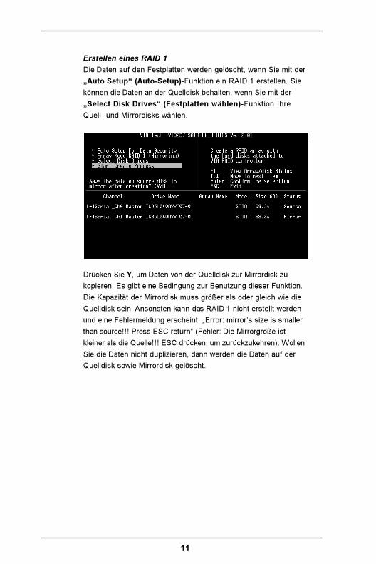
Erstellen eines RAID 1
Die Daten auf den Festplatten werden gelöscht, wenn Sie mit der
„Auto Setup“ (Auto-Setup)-Funktion ein RAID 1 erstellen. Sie
können die Daten an der Quelldisk behalten, wenn Sie mit der
„Select Disk Drives“ (Festplatten wählen)-Funktion Ihre
Quell- und Mirrordisks wählen.
Drücken Sie Y, um Daten von der Quelldisk zur Mirrordisk zu
kopieren. Es gibt eine Bedingung zur Benutzung dieser Funktion.
Die Kapazität der Mirrordisk muss größer als oder gleich wie die
Quelldisk sein. Ansonsten kann das RAID 1 nicht erstellt werden
und eine Fehlermeldung erscheint: „Error: mirror’s size is smaller
than source!!! Press ESC return“ (Fehler: Die Mirrorgröße ist
kleiner als die Quelle!!! ESC drücken, um zurückzukehren). Wollen
Sie die Daten nicht duplizieren, dann werden die Daten auf der
Quelldisk sowie Mirrordisk gelöscht.

12
Erstellen eines JBOD
Die Daten auf den Festplatten werden gelöscht, wenn Sie mit der
„Auto Setup“ (Auto-Setup)-Funktion ein JBOD erstellen. Sie
können die Daten an der ersten Festplatte des JBOD-Arrays
behalten, wenn Sie mit der „Select Disk Drives“ (Festplatten
wählen)-Funktion Ihre Festplatten wählen.
Die Daten in der ersten Festplatte werden behalten, während die
anderen Festplatten des JBOD hinter der ersten Festplatte
erweitert und unbelegt gemacht werden.
Die Expand Span (JBOD) Array (Span (JBOD)-Array
erweitern)-Funktion ist nicht verfügbar, wenn der VT8237 die 2
SATA-Anschlüsse nicht unterstützt.

13
2.3.3 Löschen eines Disk-Arrays
Sie können ein bestimmtes erstelltes RAID löschen. Folgen Sie
den nachstehenden Schritten, um ein erstelltes Disk-Array zu
löschen.
1. Markieren Sie mit Hilfe der Pfeiltasten Delete Array (Array
löschen) im Hauptmenü und drücken anschließend die
<Enter> (Eingabetaste). Die Channel (Kanal)-Spalte wird
daraufhin aktiviert.
2. Markieren Sie mit Hilfe der Pfeiltasten die zu löschende
Festplatte und drücken anschließend die <Enter>
(Eingabetaste). Ein Warnhinweis wird angezeigt. Drücken Sie
Y, um das gewählte Array zu löschen. Oder drücken Sie N,
um diesen Prozess abzubrechen.
Außer beim RAID 1 werden alle Daten auf dem Disk-Array durch
Löschen des Disk-Arrays gelöscht. Wenn Sie ein RAID 1 löschen,
werden die Daten auf den beiden Festplatten beibehalten und die
Festplatten arbeiten wie normale Laufwerke weiter.

14
2.3.4 Wählen des Boot-Arrays
Sie können ein Disk-Array als Bootgerät wählen, wenn Sie ein
Betriebssystem von einem Array starten wollen. Sie können kein
Boot-Disk-Array wählen, wenn Sie kein Betriebssystem in dem
Disk-Array installiert haben. Markieren Sie mit Hilfe der Pfeiltasten
„Select Boot Array“ (Boot-Array wählen) und drücken
anschließend die <Enter> (Eingabetaste). Die Channel (Kanal)-
Spalte wird daraufhin aktiviert. Markieren Sie mit Hilfe der
Pfeiltasten das gewünschte Array und drücken anschließend die
<Enter> (Eingabetaste). Wenn Sie ein Disk-Array, das ein
Bootzeichen hat, wählen und dann die <Enter> (Eingabetaste)
drücken, wird die Booteinstellung dieses Arrays ungültig gemacht.

15
3. Windows 2000 / Windows XP installierenZur Installation von Windows 2000 oder Windows XP legen Sie bitte die
Windows 2000- oder Windows XP-CD in das optische Laufwerk ein.
Nehmen Sie dann die Diskette aus dem Diskettenlaufwerk und starten
Sie das System neu. Gleich nach dem Neustart sehen Sie am unteren
Rand des Bildschirms die Meldung „Press F6 if you need to install a third
party SCSI or Raid driver...“.
Drücken Sie in diesem Moment auf <F6> - die folgenden Informationen
werden angezeigt.

16
Drücken Sie bitte die <S>-Taste, um die Installation von der SATA-
Treiberdiskette durchzuführen, die Sie zuvor erstellt haben. Ihnen
werden Anweisungen wie folgt angezeigt.
Nach dem Einlegen der SATA HDD-Treiberdiskette und Drücken der
Eingabetaste werden Ihnen verschiedene Versionen der SATA HDD-
Treiber zur Installation angezeigt. Bitte bewegen Sie den
Auswahlbalken mit den Pfeiltasten und treffen Sie Ihre Wahl je nach
verwendetem Betriebssystem.
Wenn die Installation der SATA HDD-Treiber abgeschlossen ist, befolgen
Sie die Anweisungen für Windows 2000 oder Windows XP weiter, um
die Installation korrekt abzuschließen.


