115
K9N Neo Series MS-7260 (V1.X) Mainboard G52-72601X1

i
K9N Neo SeriesMS-7260 (V1.X) Mainboard
G52-72601X1

ii
Copyright Notice
The material in this document is the intellectual property of MICRO-STARINTERNATIONAL. We take every care in the preparation of this document, but noguarantee is given as to the correctness of its contents. Our products are undercontinual improvement and we reserve the right to make changes without notice.
Trademarks
All trademarks are the properties of their respective owners.
NVIDIA, the NVIDIA logo, DualNet, and nForce are registered trademarks or trade-marks of NVIDIA Corporation in the United States and/or other countries.AMD, Athlon™, Athlon™ XP, Thoroughbred™, and Duron™ are registered trade-marks of AMD Corporation.Intel® and Pentium® are registered trademarks of Intel Corporation.PS/2 and OS®/2 are registered trademarks of International Business MachinesCorporation.Windows® 95/98/2000/NT/XP are registered trademarks of Microsoft Corporation.Netware® is a registered trademark of Novell, Inc.Award® is a registered trademark of Phoenix Technologies Ltd.AMI® is a registered trademark of American Megatrends Inc.
Revision History
Revision Revision History DateV1.0 First release for PCB 1.0 April 2006
Technical Support
If a problem arises with your system and no solution can be obtained from the user’smanual, please contact your place of purchase or local distributor. Alternatively,please try the following help resources for further guidance.
Visit the MSI website for FAQ, technical guide, BIOS updates, driver updates,and other information: http://www.msi.com.tw/program/service/faq/faq/esc_faq_list.phpContact our technical staff at: http://support.msi.com.tw/

iii
Safety Instructions
CAUTION: Danger of explos ion if bat tery is incorrectly replaced.Replace only with the same or equivalent type recommended by themanufacturer.
1. Always read the safety instructions carefully.2. Keep this User’s Manual for future reference.3. Keep this equipment away from humidity.4. Lay this equipment on a reliable f lat surface before setting it up.5. The openings on the enclosure are for air convection hence protects the equip-
ment from overheating. DO NOT COVER THE OPENINGS.6. Make sure the voltage of the power source and adjust properly 110/220V be-
fore connecting the equipment to the power inlet.7. Place the power cord such a way that people can not step on it. Do not place
anything over the power cord.8. Always Unplug the Power Cord before inserting any add-on card or module.9. All cautions and warnings on the equipment should be noted.10. Never pour any liquid into the opening that could damage or cause electrical
shock.11. If any of the following situations arises, get the equipment checked by a service
personnel:Ü The power cord or plug is damaged.Ü Liquid has penetrated into the equipment.Ü The equipment has been exposed to moisture.Ü The equipment has not work well or you can not get it work according to
User’s Manual.Ü The equipment has dropped and damaged.Ü The equipment has obvious sign of breakage.
12. DO NOT LEAVE THIS EQUIPMENT IN AN ENVIRONMENT UNCONDITIONED, STOR-AGE TEMPERATURE ABOVE 600 C (1400F), IT MAY DAMAGE THE EQUIPMENT.

iv
FCC-B Radio Frequency Interference Statement
This equipment has beentested and found to complywith the limits for a Class Bdigital device, pursuant to Part15 of the FCC Rules. These limits are designed to provide reasonable protectionagainst harmful interference in a residential installation. This equipment generates,uses and can radiate radio frequency energy and, if not installed and used in accor-dance with the instructions, may cause harmful interference to radio communications.However, there is no guarantee that interference will not occur in a particularinstallation. If this equipment does cause harmful interference to radio or televisionreception, which can be determined by turning the equipment off and on, the user isencouraged to try to correct the interference by one or more of the measures listedbelow.
Ü Reorient or relocate the receiving antenna.
Ü Increase the separation between the equipment and receiver.
Ü Connect the equipment into an outlet on a circuit different from that towhich the receiver is connected.
Ü Consult the dealer or an experienced radio/television technician for help.
Notice 1The changes or modif ications not expressly approved by the party responsible forcompliance could void the user’s authority to operate the equipment.
Notice 2Shielded interface cables and A.C. power cord, if any, must be used in order tocomply with the emission limits.
VOIR LA NOTICE D’INSTALLATION AVANT DE RACCORDER AU RESEAU.
Micro-Star InternationalMS-7260
This device complies with Part 15 of the FCC Rules. Operation is subject to thefollowing two conditions:(1) this device may not cause harmful interference, and(2) this device must accept any interference received, including interference that
may cause undesired operation.

v
WEEE (Waste Electrical and Electronic Equipment) Statement
vi

vii
viii
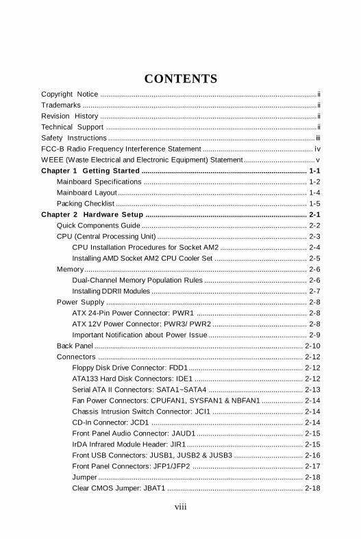
CONTENTSCopyright Notice .............................................................................................................. iiTrademarks ....................................................................................................................... iiRevision History .............................................................................................................. iiTechnical Support ........................................................................................................... iiSafety Instructions ......................................................................................................... iiiFCC-B Radio Frequency Interference Statement ........................................................ ivWEEE (Waste Electrical and Electronic Equipment) Statement .................................... vChapter 1 Getting Started .................................................................................... 1-1
Mainboard Specifications ................................................................................... 1-2Mainboard Layout ................................................................................................ 1-4Packing Checklist ................................................................................................. 1-5
Chapter 2 Hardware Setup .................................................................................. 2-1Quick Components Guide .................................................................................... 2-2CPU (Central Processing Unit) ............................................................................ 2-3
CPU Installation Procedures for Socket AM2 ............................................ 2-4Installing AMD Socket AM2 CPU Cooler Set ............................................... 2-5
Memory................................................................................................................. 2-6Dual-Channel Memory Population Rules .................................................... 2-6Installing DDRII Modules ............................................................................... 2-7
Power Supply ...................................................................................................... 2-8ATX 24-Pin Power Connector: PWR1 ........................................................ 2-8ATX 12V Power Connector: PWR3/ PWR2 ................................................ 2-8Important Notification about Power Issue .................................................. 2-9
Back Panel .......................................................................................................... 2-10Connectors ........................................................................................................ 2-12
Floppy Disk Drive Connector: FDD1 .......................................................... 2-12ATA133 Hard Disk Connectors: IDE1 ....................................................... 2-12Serial ATA II Connectors: SATA1~SATA4 ................................................ 2-13Fan Power Connectors: CPUFAN1, SYSFAN1 & NBFAN1 ..................... 2-14Chassis Intrusion Switch Connector: JCI1 .............................................. 2-14CD-In Connector: JCD1 ............................................................................. 2-14Front Panel Audio Connector: JAUD1 ...................................................... 2-15IrDA Infrared Module Header: JIR1 ........................................................... 2-15Front USB Connectors: JUSB1, JUSB2 & JUSB3 ................................... 2-16Front Panel Connectors: JFP1/JFP2 ........................................................ 2-17Jumper ........................................................................................................ 2-18Clear CMOS Jumper: JBAT1 ..................................................................... 2-18

ix
Slots .................................................................................................................... 2-19PCI (Peripheral Component Interconnect) Express Slots ....................... 2-19PCI Interrupt Request Routing ................................................................... 2-20
Chapter 3 BIOS Setup ............................................................................................ 3-1Entering Setup ..................................................................................................... 3-2
Control Keys ................................................................................................ 3-3Getting Help .................................................................................................. 3-3General Help <F1> ....................................................................................... 3-3
The Main Menu ..................................................................................................... 3-4Standard CMOS Features ................................................................................... 3-6Advanced BIOS Features ................................................................................... 3-9Advanced Chipset Features .............................................................................3-11Integrated Peripherals ....................................................................................... 3-13Power Management Setup ............................................................................... 3-16PNP/PCI Configurations ..................................................................................... 3-19H/W Monitor ........................................................................................................ 3-21Cell Menu ............................................................................................................ 3-24Load Fail-Safe/ Optimized Defaults ................................................................. 3-26BIOS Setting Password ..................................................................................... 3-27
Appendix A Realtek ALC883 Audio ...................................................................A-1Installing the Realtek HD Audio Driver ................................................................A-2
Installation for Windows 2000/XP ..............................................................A-2Software Configuration ......................................................................................A-4
Sound Effect ................................................................................................A-5Mixer .............................................................................................................A-8Audio I/O .....................................................................................................A-12Microphone ................................................................................................A-153D Audio Demo ...........................................................................................A-16Information..................................................................................................A-17
Hardware Setup ................................................................................................A-18Appendix B nVidia RAID ........................................................................................ B-1
Introduct ion ......................................................................................................... B-2System Requirement ................................................................................... B-2RAID Arrays ................................................................................................. B-2Summary of RAID Configurations ............................................................... B-2
RAID Configuration .............................................................................................. B-3Basic Configuration Instructions ................................................................ B-3Setting Up the NVRAID BIOS ....................................................................... B-3Installing the RAID Driver (for bootable RAID Array) ................................ B-7

x
NVIDIA IDE Drive/ RAID Utility Installation ........................................................... B-9Installing the NVIDIA RAID Software Under Windows .............................. B-9(for Non-bootable RAID Array) ................................................................... B-9Initializing and Using the Disk Array ......................................................... B-10
NVRAID Management Utility .............................................................................. B-12Viewing RAID Array Configurations ........................................................ B-12Setting Up a Spare RAID Disk ................................................................... B-13Morphing From One RAID Array to Another ............................................ B-17Hot Plug Array ............................................................................................ B-18Initializing a RAID Array ............................................................................. B-19Rebuilding a RAID Array ............................................................................ B-22Synchronizing a RAID Array ..................................................................... B-25
Appendix C nVidia System Driver ..................................................................... C-1nVidia System Driver Installation ........................................................................ C-2
NVIDIA System Driver .................................................................................. C-2nVidia Utility Installation ....................................................................................... C-5

1-1
Getting Started
Getting StartedChapter 1
Thank you for choosing the K9N Neo Series (MS-7260v1.X) ATX mainboard. The K9N Neo Series mainboardsare based on nVIDIA® nForce 550 chipsets for optimalsystem efficiency. Designed to fit the advanced AMD®
Athlon 64/ X2 & Sempron processor, the K9N NeoSeries deliver a high performance and professionaldesktop platform solution.
MS-7260 Mainboard
1-2
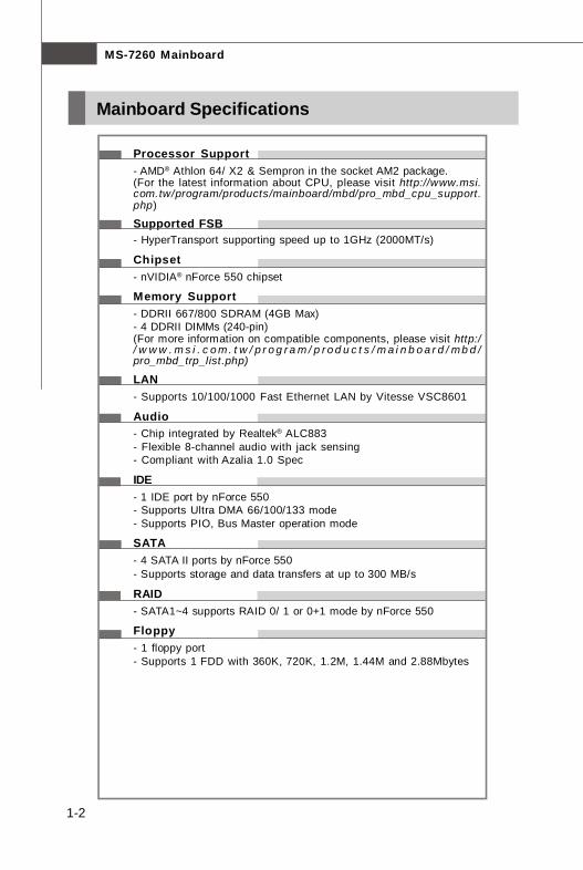
Processor Support- AMD® Athlon 64/ X2 & Sempron in the socket AM2 package.(For the latest information about CPU, please visit http://www.msi.com.tw/program/products/mainboard/mbd/pro_mbd_cpu_support.php)
Supported FSB- HyperTransport supporting speed up to 1GHz (2000MT/s)
Chipset- nVIDIA® nForce 550 chipset
Memory Support- DDRII 667/800 SDRAM (4GB Max)- 4 DDRII DIMMs (240-pin)(For more information on compatible components, please visit http:// w w w . m s i . c o m. t w / p r o g r a m / p r o d u c t s / m a i n b o a r d / mb d /pro_mbd_trp_list.php)
LAN- Supports 10/100/1000 Fast Ethernet LAN by Vitesse VSC8601
Audio- Chip integrated by Realtek® ALC883- Flexible 8-channel audio with jack sensing- Compliant with Azalia 1.0 Spec
IDE- 1 IDE port by nForce 550- Supports Ultra DMA 66/100/133 mode- Supports PIO, Bus Master operation mode
SATA- 4 SATA II ports by nForce 550- Supports storage and data transfers at up to 300 MB/s
RAID- SATA1~4 supports RAID 0/ 1 or 0+1 mode by nForce 550
Floppy- 1 floppy port- Supports 1 FDD with 360K, 720K, 1.2M, 1.44M and 2.88Mbytes
Mainboard Specifications
1-3
Getting Started
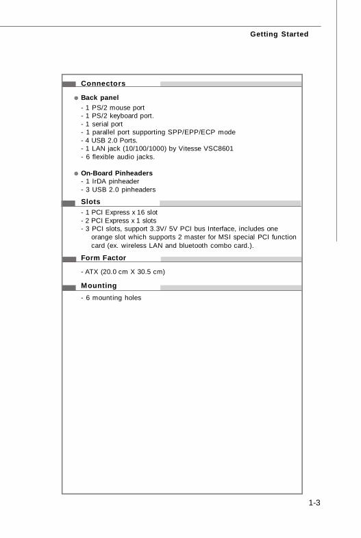
Connectors
Back panel- 1 PS/2 mouse port- 1 PS/2 keyboard port.- 1 serial port- 1 parallel port supporting SPP/EPP/ECP mode- 4 USB 2.0 Ports.- 1 LAN jack (10/100/1000) by Vitesse VSC8601- 6 flexible audio jacks.
On-Board Pinheaders- 1 IrDA pinheader- 3 USB 2.0 pinheaders
Slots- 1 PCI Express x 16 slot- 2 PCI Express x 1 slots- 3 PCI slots, support 3.3V/ 5V PCI bus Interface, includes one
orange slot which supports 2 master for MSI special PCI functioncard (ex. wireless LAN and bluetooth combo card.).
Form Factor
- ATX (20.0 cm X 30.5 cm)
Mounting- 6 mounting holes

MS-7260 Mainboard
1-4
K9N Neo Series(MS-7260 v1.X) ATX Mainboard
Mainboard Layout
BIOS
JPW1
JUSB2JUSB3FDD1
JCI1
IDE
1
DIM
M1
DIM
M2
DIM
M3
WinbondI/O
DIM
M4
Top : mouse Bottom: keyboard
Top : Parallel Port
Bottom: COM Port
PCI 3
PCI 2ALC883
PCI 1
PCI _EX3
PCI _EX2
JCD1JAUD1
CPUFAN1
SYSFAN1
USB ports
T: LAN jackB: USB ports
T:M:B:
Line-InLine-OutMic
PCI _EX1JIR1
ATX
2
LANChip
T:SS-OutM:CSB:RS-Out
-Out
BATT+
nvidianForce 550
SA
TA3
SAT
A4
JBAT1
JUSB1
SAT
A1
SA
TA2
JFP1
JFP2
NBFAN1

1-5
Getting Started
Packing Checklist
SATA Cable
MSI motherboard MSI Driver/Utility CD
* The pictures are for reference only and may vary from the packing contents of theproduct you purchased.
Back IO Shield User’s Guide
Standard Cable forIDE Devices
Standard Cable forFloppy Disk
Power Cable

MS-7260 Mainboard
1-6
MSI Special Feature
Cool’n’QuietThis utility provides a CPU temperature detection function called Cool’n’Quiet.Cool’n’Quiet is a special feature designed only for AMD® Athlon64 processor, andwith Cool’n’Quiet, the system will be capable of detecting the temperature of theCPU according to the CPU’s working loading. When the CPU temperature climbs up toa certain degree, the speed of the system cooling fan will be risen automatically. Onthe other hand, the speed of the system cooling fan will slow down instantly whenthe CPU temperature descends to its normal degree.
Here the current system status (including Vcore, 3.3V, +5V and 12V) and the currentPC hardware status (such as the CPU & system temperatures and all fans speeds)are shown on the left and right sides for you to monitor.When you click the red triangles in the left and right sides, two sub-menus will openfor users to overclock, overspec or to adjust the thresholds of system to send out thewarning messages.
Core CenterThe Core Center is a new utility you can find in the CD-ROM disk. The utility is just likeyour PC doctor that can detect, view and adjust the PC hardware and system statusduring real time operation.

1-7
Getting Started
Left-side: Current system statusIn the left sub-menu, you can configure the settings of FSB, Vcore, Memory Voltageand AGP Voltage by clicking the radio button in front of each item and make it available(the radio button will be lighted as yellow when selected), use the “+” and “-” buttonsto adjust, then click “OK” to apply the changes. Then you can click “Save” to savethe desired FSB you just configured.
Right-side: PC hardware status during real time operationIn the right sub-menu, here you can configure the PC hardware status such as CPU& system temperatures and fan speeds. You may use the scroll bars to adjust eachitem, then click “OK” to apply the changes. The values you set for the temperaturesare the maximum thresholds for the system warnings, and the values for fan speedsare the minimum thresholds.
Center-side: Cool’n’Quiet / User modeHere you may adjust the CPU fan speed. If you choose User mode, you may adjustthe CPU fan speed in 8 different modes, from High Speed to Low speed. If youchoose Cool’n’Quiet, the system will automatically configure an optimal setting foryou.
Important
To ensure that Cool’n’Quiet functionis activated and will be work ingproperly, it is required to double con-firm that:1. Run BIOS Setup, and select H/W
Monitor. Under H/W Monitor ,find Cool’n’Quiet, and set thisitem to [Enable].
2. E nt er W ind ow s , an d s e lec t[S ta r t ] -> [S et t in gs ] - > [C on t r o lPannel]->[Power Options]. EnterPower Options Properties tag,and select Minimal Power Man-agement under Power schemes.

2-1
Hardware Setup
Hardware SetupChapter 2
This chapter provides you with the information abouthardware setup procedures. While doing the installation,be careful in holding the components and follow theinstallation procedures. For some components, if youinstall in the wrong orientation, the components will notwork properly.
Use a grounded wrist strap before handling computercomponents. S tatic elec tr ic ity may damage thecomponents.
2-2
MS-7260 Mainboard
DDRII DIMMs, p.2-6
JFP1, p.2-17
Back Panel
I/O, p.2-10
JPW1, p.2-8
IDE1, p.2-12
PCI Slots,
p.2-20
JUSB1~3, p.2-16
SATA1~4,p.2-13
JBAT1, p.2-16
FDD1, p.2-12
PCIE Slots,
p.2-19
CPU, p.2-3
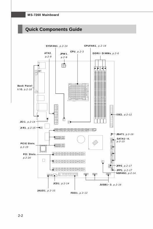
Quick Components Guide
JAUD1, p.2-15
JFP2, p.2-17
JCD1, p.2-14
ATX2, p.2-8
NBFAN1, p.2-14
SYSFAN1, p.2-14
JIR1, p.2-15
JCI1, p.2-14
CPUFAN1, p.2-14

2-3
Hardware Setup
The mainboard supports AMD® Athlon 64/ X2 & Sempron processors. The mainboarduses a CPU socket called Socket AM2 (940-pin) for easy CPU installation. When youare installing the CPU, make sure the CPU has a heat sink and a cooling fanattached on the top to prevent overheating. If you do not have the heat sink andcooling fan, contact your dealer to purchase and install them before turning on thecomputer.For the latest information about CPU, please visit http://www.msi.com.tw/program/products/mainboard/mbd/pro_mbd_cpu_support.php
CPU (Central Processing Unit)
Important
1. Overheating will seriously damage the CPU and system. Always makesure the cooling fan can work properly to protect the CPU from overheating.
2. Make sure that you apply an even layer of heat sink paste (or thermal tape)between the CPU and the heatsink to enhance heat dissipation.
3. While replacing the CPU, always turn off the ATX power supply or unplugthe power supply’s power cord from the grounded outlet first to ensure thesafety of CPU.

2-4
MS-7260 Mainboard
CPU Installation Procedures for Socket AM2
1. Please turn off the power andunplug the power cord beforeinstalling the CPU.
2. Pull the lever s ideways awayfrom the socket. Make sure toraise the lever up to a 90-de-gree angle.
3. Look for the gold arrow of theCPU. The gold arrow shouldpoint as shown in the picture.The CPU can only fit in the cor-rect orientation.
4. If the CPU is correctly installed,the pins should be completelyembedded into the socket andcan not be seen. Please notethat any violation of the correctinstal lat ion procedures maycause permanent damages toyour mainboard.
5. Press the CPU down firmly intothe socket and close the lever.As the CPU is likely to move whilethe lever is being closed, al-ways close the lever with yourfingers pressing tightly on top ofthe CPU to make sure the CPU isproperly and completely embed-ded into the socket.
Open Lever
90 degreeSliding Plate
Gold arrow
Gold arrow
Gold arrow
Correc t CPU placement
O
2-5
Hardware Setup
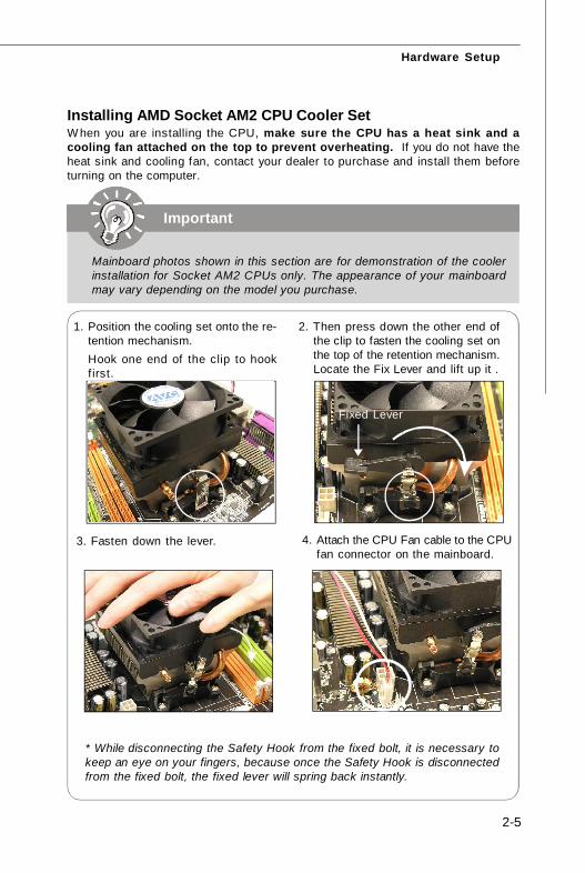
Installing AMD Socket AM2 CPU Cooler SetW hen you are installing the CPU, make sure the CPU has a heat sink and acooling fan attached on the top to prevent overheating. If you do not have theheat sink and cooling fan, contact your dealer to purchase and install them beforeturning on the computer.
Mainboard photos shown in this section are for demonstration of the coolerinstallation for Socket AM2 CPUs only. The appearance of your mainboardmay vary depending on the model you purchase.
Important
2. Then press down the other end ofthe clip to fasten the cooling set onthe top of the retention mechanism.Locate the Fix Lever and lift up it .
1. Position the cooling set onto the re-tention mechanism.Hook one end of the clip to hookfirst.
3. Fasten down the lever. 4. Attach the CPU Fan cable to the CPUfan connector on the mainboard.
Fixed Lever
* While disconnecting the Safety Hook from the fixed bolt, it is necessary tokeep an eye on your fingers, because once the Safety Hook is disconnectedfrom the fixed bolt, the fixed lever will spring back instantly.
2-6
MS-7260 Mainboard
Memory
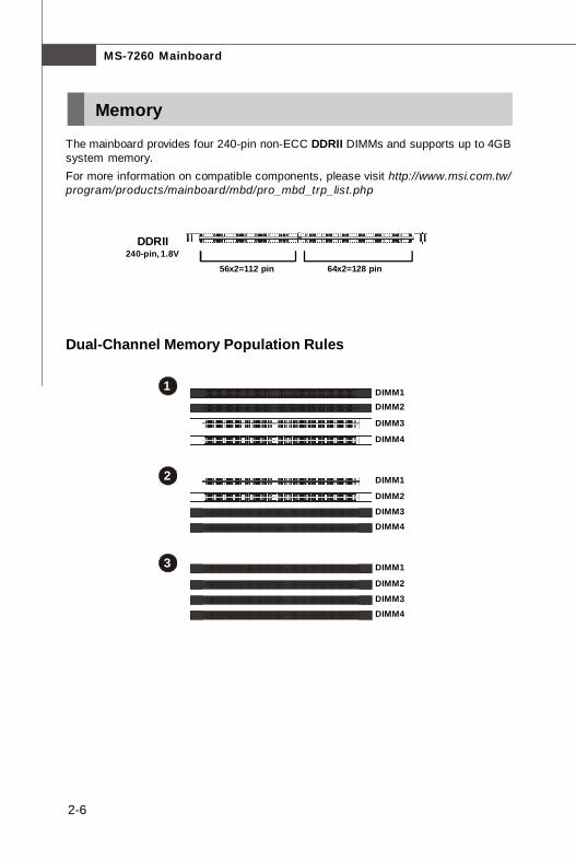
The mainboard provides four 240-pin non-ECC DDRII DIMMs and supports up to 4GBsystem memory.For more information on compatible components, please visit http://www.msi.com.tw/program/products/mainboard/mbd/pro_mbd_trp_list.php
DDRII240-pin, 1.8V
1 DIMM1 DIMM2
DIMM3
DIMM4
2 DIMM1
DIMM2
DIMM3 DIMM4
3 DIMM1
DIMM2
DIMM3 DIMM4
Dual-Channel Memory Population Rules
64x2=128 pin56x2=112 pin
2-7
Hardware Setup
Important
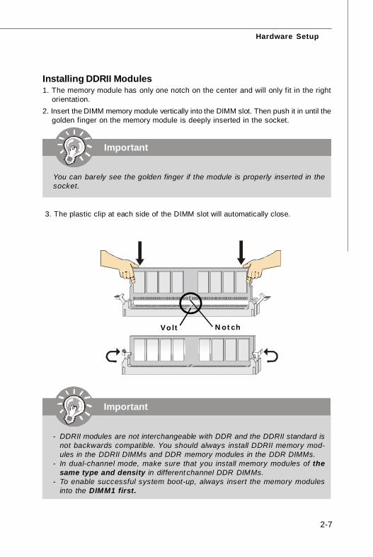
- DDRII modules are not interchangeable with DDR and the DDRII standard isnot backwards compatible. You should always install DDRII memory mod-ules in the DDRII DIMMs and DDR memory modules in the DDR DIMMs.
- In dual-channel mode, make sure that you install memory modules of thesame type and density in different channel DDR DIMMs.
- To enable successful system boot-up, always insert the memory modulesinto the DIMM1 first.
Installing DDRII Modules1. The memory module has only one notch on the center and will only fit in the right
orientation.2. Insert the DIMM memory module vertically into the DIMM slot. Then push it in until the
golden finger on the memory module is deeply inserted in the socket.
3. The plastic clip at each side of the DIMM slot will automatically close.
Volt Notch
Important
You can barely see the golden finger if the module is properly inserted in thesocket.
2-8
MS-7260 Mainboard
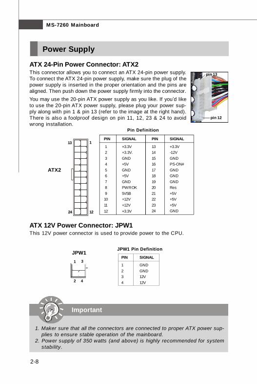
Power Supply
PIN SIGNAL
13 +3.3V14 -12V15 GND16 PS-ON#17 GND18 GND19 GND20 Res21 +5V22 +5V23 +5V24 GND
PIN SIGNAL
1 +3.3V 2 +3.3V. 3 GND 4 +5V 5 GND 6 +5V 7 GND 8 PWR OK 9 5VSB10 +12V11 +12V12 +3.3V
Pin Definition
PIN SIGNAL
1 GND2 GND3 12V4 12V
JPW1 Pin Definition
pin 12
pin 13
JPW11 3
42
1
ATX2
1224
13
Important
1. Maker sure that all the connectors are connected to proper ATX power sup-plies to ensure stable operation of the mainboard.
2. Power supply of 350 watts (and above) is highly recommended for systemstability.
ATX 24-Pin Power Connector: ATX2This connector allows you to connect an ATX 24-pin power supply.To connect the ATX 24-pin power supply, make sure the plug of thepower supply is inserted in the proper orientation and the pins arealigned. Then push down the power supply firmly into the connector.You may use the 20-pin ATX power supply as you like. If you’d liketo use the 20-pin ATX power supply, please plug your power sup-ply along with pin 1 & pin 13 (refer to the image at the right hand).There is also a foolproof design on pin 11, 12, 23 & 24 to avoidwrong installation.
ATX 12V Power Connector: JPW1This 12V power connector is used to provide power to the CPU.

2-9
Hardware Setup
Important Notification about Power IssueNForce chipset is very sensitive to ESD (Electrostatic Discharge), therefore thisissue mostly happens while the users intensively swap memory modules under S5(power-off) states, and the power code is plugged while installing modules. Due toseveral pins are very sensitive to ESD, so this kind of memory-replacement actionsmight cause system chipset unable to boot. Please follow the following solution toavoid this situation.
Unplug the AC power cable (shown in figure 1) or unplug the ATX2 & JPW1 powerconnectors (shown in figure 2 & figure 3) before the 1st installation or during systemupgrade procedure.
Figure 1:Unplug the AC power cable
Figure 2:Unplug the ATX2 power conn.
Figure 3:Unplug the JPW1 power conn.

2-10
MS-7260 Mainboard
Back Panel
Keyboard USB Ports
L-In
Mouse LANParallel Port
SS-OutCS-Out
RS-Out
L-OutMic
Serial Port
Mouse/Keyboard ConnectorThe standard PS/2® mouse/keyboard DIN connector is for a PS/2® mouse/keyboard.
Parallel Port ConnectorA parallel port is a standard printer port that supports Enhanced Parallel Port (EPP)and Extended Capabilities Parallel Port (ECP) mode.
Serial Port ConnectorThe serial port is a 16550A high speed communications port that sends/ receives 16bytes FIFOs. You can attach a serial mouse or other serial devices directly to theconnector.
LAN (RJ-45) JackThe standard RJ-45 jack is for connectionto single Local Area Network (LAN). Youcan connect a network cable to it.
Link Indicator
(Right LED)
Activity Indicator
(Left LED)
LED Color LED State condition
Off LAN link is not established.
Left Yellow On (steady state) LAN link is established.
On (brighter & pulsing) The computer is communicating with another computer on the LAN.
Green Off 10 Mbit/sec data rate is selected.
Right On 100 Mbit/sec data rate is selected.Orange On 1000 Mbit/sec data rate is selected.
LAN

2-11
Hardware Setup
USB ConnectorsThe OHCI (Open Host Controller Interface) Universal Serial Bus root is for attachingUSB devices such as keyboard, mouse, or other USB-compatible devices.
Audio Port ConnectorsThese audio connectors are used for audio devices. You can differentiate the colorof the audio jacks for different audio sound effects.
Green audio jack - Line Out, is a connector for speakers or headphones. Blue audio jack - Line In / Side-Surround Out in 7.1 channel mode, is used
for external CD player, tapeplayer or other audiodevices.
Pink audio jack - Mic In, is a connector for microphones. Orange audio jack - Center/ Subwoofer Out in 5.1/ 7.1 channel mode. Black audio jack - Rear-Surround Out in 5.1/ 7.1 channel mode. Gray audio jack - Side-Surround Out in 7.1 channel mode.
2-12
MS-7260 Mainboard
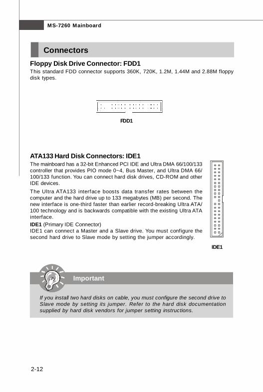
ConnectorsFloppy Disk Drive Connector: FDD1This standard FDD connector supports 360K, 720K, 1.2M, 1.44M and 2.88M floppydisk types.
FDD1
IDE1 (Primary IDE Connector)IDE1 can connect a Master and a Slave drive. You must configure thesecond hard drive to Slave mode by setting the jumper accordingly.
IDE1
ATA133 Hard Disk Connectors: IDE1The mainboard has a 32-bit Enhanced PCI IDE and Ultra DMA 66/100/133controller that provides PIO mode 0~4, Bus Master, and Ultra DMA 66/100/133 function. You can connect hard disk drives, CD-ROM and otherIDE devices.The Ultra ATA133 interface boosts data transfer rates between thecomputer and the hard drive up to 133 megabytes (MB) per second. Thenew interface is one-third faster than earlier record-breaking Ultra ATA/100 technology and is backwards compatible with the existing Ultra ATAinterface.
Important
If you install two hard disks on cable, you must configure the second drive toSlave mode by setting its jumper. Refer to the hard disk documentationsupplied by hard disk vendors for jumper setting instructions.

2-13
Hardware Setup
PIN SIGNAL PIN SIGNAL
1 GND 2 TXP
3 TXN 4 GND5 RXN 6 RXP7 GND
Pin Definition
Connect to SATA connector
Take out the dust coverand connect to the harddisk devices
Serial ATA cable
Serial ATA II Connectors: SATA1~SATA4SATA1~SATA4 are high-speed SATAII interface ports. Each supports data rates of300 MB/s and is fully compliant with Serial ATA specifications. Each Serial ATA con-nector can connect to 1 hard disk device.
Important
Please do not fold the Serial ATA cable into 90-degree angle. Otherwise,data loss may occur during transmission.
SATA2
SATA1
SATA3
SATA41
7
2-14
MS-7260 Mainboard
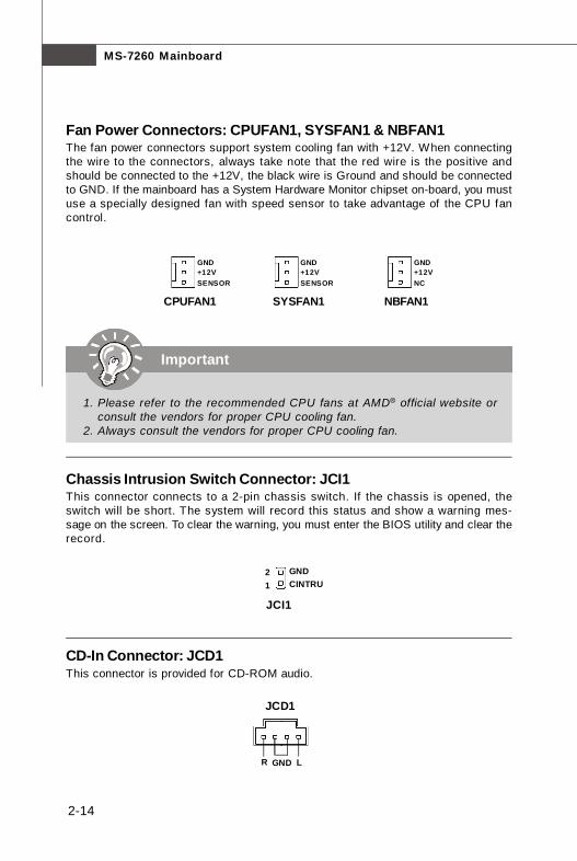
Fan Power Connectors: CPUFAN1, SYSFAN1 & NBFAN1The fan power connectors support system cooling fan with +12V. When connectingthe wire to the connectors, always take note that the red wire is the positive andshould be connected to the +12V, the black wire is Ground and should be connectedto GND. If the mainboard has a System Hardware Monitor chipset on-board, you mustuse a specially designed fan with speed sensor to take advantage of the CPU fancontrol.
CPUFAN1 SYSFAN1
Chassis Intrusion Switch Connector: JCI1This connector connects to a 2-pin chassis switch. If the chassis is opened, theswitch will be short. The system will record this status and show a warning mes-sage on the screen. To clear the warning, you must enter the BIOS utility and clear therecord.
JCI1
21
GNDCINTRU
CD-In Connector: JCD1This connector is provided for CD-ROM audio.
JCD1
GNDR L
SENSOR+12VGND
SENSOR+12VGND
NC+12VGND
NBFAN1
Important
1. Please refer to the recommended CPU fans at AMD® official website orconsult the vendors for proper CPU cooling fan.
2. Always consult the vendors for proper CPU cooling fan.

2-15
Hardware Setup
Front Panel Audio Connector: JAUD1The JAUD1 front panel audio connector allows you to connect the front panel audioand is compliant with Intel® Front Panel I/O Connectivity Design Guide.
JAUD1 Pin Definition
JAUD112
910
PIN SIGNAL DESCRIPTION
1 PORT 1L Analog Port 1 - Left channel2 GND Ground3 PORT 1R Analog Port 1 - Right channel4 PRESENCE# Active low signal - signals BIOS that a High Definition Audio
dongle is connected to the analog header. PRESENCE# = 0when a High Definition Audio dongle is connected.
5 PORT 2R Analog Port 2 - Right channel6 SENSE1_RETIRN Jack detection return from front panel JACK17 SENSE_SEND Jack detection sense line from the High Definition Audio CODEC
jack detection resistor network8 KEY Connector Key9 PORT 2L Analog Port 2 - Left channel10 SENSE2_RETIRN Jack detection return from front panel JACK2
IrDA Infrared Module Header: JIR1The connector allows you to connect to IrDA Infrared module. You must configure thesetting through the BIOS setup to use the IR function. JIR1 is compliant with Intel®Front Panel I/O Connectivity Design Guide.
Pin Signal
1 NC2 NC3 VCC54 GND5 IRTX6 IRRX
Pin Definition
JIR1
65
21

2-16
MS-7260 Mainboard
Front USB Connectors: JUSB1, JUSB2 & JUSB3The mainboard provides USB 2.0 pinheaders (optional USB 2.0 bracket available) thatare compliant with Intel® I/O Connectivity Design Guide. USB 2.0 technology increasesdata transfer rate up to a maximum throughput of 480Mbps, which is 40 times fasterthan USB 1.1, and is ideal for connecting high-speed USB interface peripherals suchas USB HDD, digital cameras, MP3 players, printers, modems and the like.
12
910
JUSB1/2/3PIN SIGNAL PIN SIGNAL1 VCC 2 VCC
3 USB0- 4 USB1-5 USB0+ 6 USB1+
7 GND 8 GND
9 Key (no pin) 10 USBOC
Pin Definition
Connected to USB connectorUSB 2.0 Bracket
(Optional)
Important
Note that the pins of VCC and GND must be connected correctly to avoidpossible damage.

2-17
Hardware Setup
PIN SIGNAL DESCRIPTION
1 HD_LED + Hard disk LED pull-up2 FP PWR/SLP MSG LED pull-up3 HD_LED - Hard disk active LED4 FP PWR/SLP MSG LED pull-up5 RST_SW - Reset Switch low reference pull-down to GND6 PWR_SW + Power Switch high reference pull-up7 RST_SW + Reset Switch high reference pull-up8 PWR_SW - Power Switch low reference pull-down to GND9 RSVD_DNU Reserved. Do not use.
JFP1 Pin Definition
PIN SIGNAL DESCRIPTION
1 GND Ground2 SPK- Speaker-3 SLED Suspend LED4 BUZ+ Buzzer+5 PLED Power LED6 BUZ- Buzzer-7 NC No connection8 SPK+ Speaker+
JFP2 Pin Definition
Front Panel Connectors: JFP1/JFP2The mainboard provides two front panel connectors for electrical connection to thefront panel switches and LEDs. The JFP1 is compliant with Intel® Front Panel I/OConnectivity Design Guide.
12
910
JFP1
HDDLED
ResetSwitch
PowerLED
PowerSwitch
+
++
--
-
78
PowerLED
Speaker
12
JFP2+
+-
-
2-18
MS-7260 Mainboard
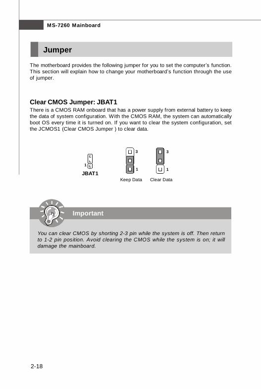
Jumper
The motherboard provides the following jumper for you to set the computer’s function.This section will explain how to change your motherboard’s function through the useof jumper.
Clear CMOS Jumper: JBAT1There is a CMOS RAM onboard that has a power supply from external battery to keepthe data of system configuration. With the CMOS RAM, the system can automaticallyboot OS every time it is turned on. If you want to clear the system configuration, setthe JCMOS1 (Clear CMOS Jumper ) to clear data.
JBAT11
Clear Data
3
1
Keep Data
3
1
Important
You can clear CMOS by shorting 2-3 pin while the system is off. Then returnto 1-2 pin position. Avoid clearing the CMOS while the system is on; it willdamage the mainboard.
2-19
Hardware Setup
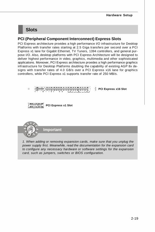
PCI (Peripheral Component Interconnect) Express SlotsPCI Express architecture provides a high performance I/O infrastructure for DesktopPlatforms with transfer rates starting at 2.5 Giga transfers per second over a PCIExpress x1 lane for Gigabit Ethernet, TV Tuners, 1394 controllers, and general pur-pose I/O. Also, desktop platforms with PCI Express Architecture will be designed todeliver highest performance in video, graphics, multimedia and other sophisticatedapplications. Moreover, PCI Express architecture provides a high performance graphicsinfrastructure for Desktop Platforms doubling the capability of existing AGP 8x de-signs with transfer rates of 4.0 GB/s over a PCI Express x16 lane for graphicscontrollers, while PCI Express x1 supports transfer rate of 250 MB/s.
Slots
PCI Express x16 Slot
PCI Express x1 Slot
Important
1. When adding or removing expansion cards, make sure that you unplug thepower supply first. Meanwhile, read the documentation for the expansion cardto configure any necessary hardware or software settings for the expansioncard, such as jumpers, switches or BIOS configuration.

2-20
MS-7260 Mainboard
32-bit PCI Slot
PCI (Peripheral Component Interconnect) SlotsThe PCI slots support LAN cards, SCSI cards, USB cards, and other add-on cardsthat comply with PCI specifications. At 32 bits and 33 MHz, it yields a throughput rateof 133 MBps.
PCI Interrupt Request RoutingThe IRQ, acronym of interrupt request line and pronounced I-R-Q, are hardware linesover which devices can send interrupt signals to the microprocessor. The PCI IRQpins are typically connected to the PCI bus pins as follows:
Order 1 Order 2 Order 3 Order 4
PCI Slot 1 INT E# INT F# INT G# INT H#
PCI Slot 2 INT F# INT G# INT H# INT E#
PCI Slot 3 INT G# INT H# INT E# INT F#

BIOS Setup
3-1
Chapter 3
BIOS Setup
This chapter provides information on the BIOS Setupprogram and allows you to configure the system foroptimum use.You may need to run the Setup program when:
² An error message appears on the screen during thesystem booting up, and requests you to run SETUP.
² You want to change the default settings for cus-tomized features.
MS-7260 Mainboard
3-2
Entering Setup
Important
1. The items under each BIOS category described in this chapter are undercontinuous update for better system performance. Therefore, the descrip-tion may be slightly different from the latest BIOS and should be held forreference only.
2. Upon boot-up, the 1st line appearing after the memory count is the BIOSversion. It is usually in the format:
A7260NMS V1.0 041506 where:
1st digit refers to BIOS maker as A = AMI, W = AWARD, and P =PHOENIX.2nd - 5th digit refers to the model number.6th digit refers to the chipset as I = Intel, N = nVidia, and V = VIA.7th - 8th digit refers to the customer as MS = all standard customers.V1.0 refers to the BIOS version.041506 refers to the date this BIOS was released.
Power on the computer and the system will start POST (Power On Self Test) process.When the message below appears on the screen, press <DEL> key to enter Setup.
Press DEL to enter SETUP
If the message disappears before you respond and you still wish to enter Setup,restart the system by turning it OFF and On or pressing the RESET button. You mayalso restart the system by simultaneously pressing <Ctrl>, <Alt>, and <Delete> keys.

BIOS Setup
3-3
Getting HelpAfter entering the Setup menu, the first menu you will see is the Main Menu.
Main MenuThe main menu lists the setup functions you can make changes to. You can use thearrow keys ( ↑↓ ) to select the item. The on-line description of the highlighted setupfunction is displayed at the bottom of the screen.
Sub-MenuIf you find a right pointer symbol (as shown in theright view) appears to the left of certain fields thatmeans a sub-menu can be launched from this field. Asub-menu contains additional options for a f ieldparameter. You can use arrow keys ( ↑↓ ) to high-light the field and press <Enter> to call up the sub-menu. Then you can use the controlkeys to enter values and move from field to field within a sub-menu. If you want toreturn to the main menu, just press the <Esc >.
General Help <F1>The BIOS setup program provides a General Help screen. You can call up this screenfrom any menu by simply pressing <F1>. The Help screen lists the appropriate keysto use and the possible selections for the highlighted item. Press <Esc> to exit theHelp screen.
Control Keys
<↑> Move to the previous item<↓> Move to the next item<←> Move to the item in the left hand<→> Move to the item in the right hand<Enter> Select the item<Esc> Jumps to the Exit menu or returns to the main menu from a
submenu<+/PU> Increase the numeric value or make changes<-/PD> Decrease the numeric value or make changes<F6> Load Optimized Defaults<F7> Load Fail-Safe Defaults<F10> Save all the CMOS changes and exit

MS-7260 Mainboard
3-4
Standard CMOS FeaturesUse this menu for basic system configurations, such as time, date etc.
Advanced BIOS FeaturesUse this menu to setup the items of AMI® special enhanced features.
Advanced Chipset FeaturesUse this menu to change the values in the chipset registers and optimize your system’sperformance.
Integrated PeripheralsUse this menu to specify your settings for integrated peripherals.
Power Management SetupUse this menu to specify your settings for power management.
PNP/PCI ConfigurationsThis entry appears if your system supports PnP/PCI.
H/W MonitorThis entry shows your PC health status.
Cell MenuUse this menu to specify your settings for frequency/voltage control and overclocking.
The Main Menu
BIOS Setup
3-5
Load Optimized DefaultsUse this menu to load the default values set by the mainboard manufacturer specifi-cally for optimal performance of the mainboard.
BIOS Setting PasswordUse this menu to set the password for BIOS.
Save & Exit SetupSave changes to CMOS and exit setup.
Exit Without SavingAbandon all changes and exit setup.

MS-7260 Mainboard
3-6
The items in Standard CMOS Features Menu includes some basic setup items. Usethe arrow keys to highlight the item and then use the <PgUp> or <PgDn> keys to selectthe value you want in each item.
Date (MM:DD:YY)This allows you to set the system to the date that you want (usually the current date).The format is <day><month> <date> <year>.
day Day of the week, from Sun to Sat, determined byBIOS. Read-only.
month The month from Jan. through Dec.date The date from 1 to 31 can be keyed by numeric function keys.year The year can be adjusted by users.
Time (HH:MM:SS)This allows you to set the system time that you want (usually the current time). Thetime format is <hour> <minute> <second>.
IDE Primary Master/ Slave, Serial-ATA 0/1 Primary/ Secondary ChannelPress <Enter> to enter the sub-menu, and the following screen appears.
Standard CMOS Features
BIOS Setup
3-7
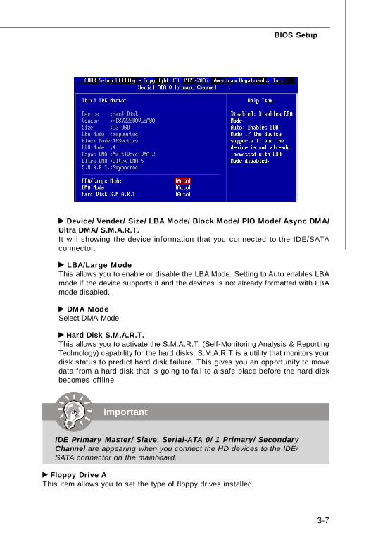
Device/ Vender/ Size/ LBA Mode/ Block Mode/ PIO Mode/ Async DMA/Ultra DMA/ S.M.A.R.T.It will showing the device information that you connected to the IDE/SATAconnector.
LBA/Large ModeThis allows you to enable or disable the LBA Mode. Setting to Auto enables LBAmode if the device supports it and the devices is not already formatted with LBAmode disabled.
DMA ModeSelect DMA Mode.
Hard Disk S.M.A.R.T.This allows you to activate the S.M.A.R.T. (Self-Monitoring Analysis & ReportingTechnology) capability for the hard disks. S.M.A.R.T is a utility that monitors yourdisk status to predict hard disk failure. This gives you an opportunity to movedata from a hard disk that is going to fail to a safe place before the hard diskbecomes off line.
Important
IDE Primary Master/ Slave, Serial-ATA 0/ 1 Primary/ SecondaryChannel are appearing when you connect the HD devices to the IDE/SATA connector on the mainboard.
Floppy Drive AThis item allows you to set the type of floppy drives installed.

MS-7260 Mainboard
3-8
Usage Memory/ BIOS VersionThese items show the CPU information, BIOS version and memory status of yoursystem (read only).
Halt OnThe setting determines whether the system will stop if an error is detected at boot.Available options are:
[No Errors] The system doesn’t stop for any detected error.[All, But Keyboard] The system doesn’t stop for a keyboard error.
System InformationPress <Enter> to enter the sub-menu, and the following screen appears.

BIOS Setup
3-9
Quick BootingSetting the item to [Enabled] allows the system to boot within 5 seconds since it willskip some check items.
Full Screen LOGO DisplayThis item enables you to show the company logo on the bootup screen. Settings are:
[Enabled] Shows a still image (logo) on the full screen at boot.[Disabled] Shows the POST messages at boot.
Boot Up NumLock LEDThis setting is to set the Num Lock status when the system is powered on. Setting to[On] will turn on the Num Lock key when the system is powered on. Setting to [Off]will allow users to use the arrow keys on the numeric keypad.
Boot To OS/2This allows you to run the OS/2® operating system with DRAM larger than 64MB.When you choose [No], you cannot run the OS/2® operating system with DRAMlarger than 64MB. But it is possible if you choose [Yes].
IOAPIC FunctionThis field is used to enable or disable the APIC (Advanced Programmable InterruptController). Due to compliance with PC2001 design guide, the system is able to run inAPIC mode. Enabling APIC mode will expand available IRQ resources for the system.
Advanced BIOS Features

MS-7260 Mainboard
3-10
1st Boot DeviceThe items allow you to set the sequence of boot devices where BIOS attemptsto load the disk operating system.
Hard Disk DrivesThis feature allows you to specify the hard disk boot priority.
Removable DrivesThis feature allows you to specify the removable device boot priority.
CD/DVD DrivesThis feature allows you to specify the CD/DVD device boot priority.
Other DrivesThis feature allows you to specify the other device boot priority.
MPS Table VersionThis field allows you to select which MPS (Multi-Processor Specification) version tobe used for the operating system. You need to select the MPS version supported byyour operating system. To find out which version to use, consult the vendor of youroperating system.
Boot SequencePress <Enter> to enter the sub-menu and the following screen appears:

BIOS Setup
3-11
Advanced Chipset Features
Memory ConfigurationPress <Enter> to enter the sub-menu and the following screen appears:
Memclock ModeSelect the DRAM frequency programming method. If set to “Auto”, the DRAMspeed will be based on SPDs. If set to “Limit”, the DRAM speed will not exceedthe specif ied value. If set to “Manual”, the DRAM speed specified will be pro-grammed regardless of SPD.
MCT Timing ModeThis field has the capacity to automatically detect all of the DRAM timing. If youset this field to [Manual], the following fields will be selectable.
MS-7260 Mainboard
3-12
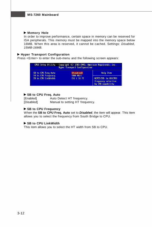
Memory HoleIn order to improve performance, certain space in memory can be reserved forISA peripherals. This memory must be mapped into the memory space below16MB. W hen this area is reserved, it cannot be cached. Settings: Disabled,15MB-16MB.
Hyper Transport ConfigurationPress <Enter> to enter the sub-menu and the following screen appears:
SB to CPU Freq. Auto[Enabled] Auto Detect HT frequency.[Disabled] Manual to setting HT frequency.
SB to CPU FrequencyWhen the SB to CPU Freq. Auto set to Disabled, the item will appear. This itemallows you to select the frequency from South Bridge to CPU.
SB to CPU LinkWidthThis item allows you to select the HT width from SB to CPU.
BIOS Setup
3-13
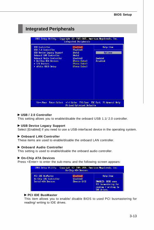
USB / 2.0 ControllerThis setting allows you to enable/disable the onboard USB 1.1/ 2.0 controller.
USB Device Legacy SupportSelect [Enabled] if you need to use a USB-interfaced device in the operating system.
Onboard LAN ControllerThese items are used to enable/disable the onboard LAN controller.
Onboard Audio ControllerThis setting is used to enable/disable the onboard audio controller.
On-Chip ATA DevicesPress <Enter> to enter the sub-menu and the following screen appears:
PCI IDE BusMasterThis item allows you to enable/ disable BIOS to used PCI busmastering forreading/ writing to IDE drives.
Integrated Peripherals

MS-7260 Mainboard
3-14
On-Chip IDE ControllerThis item allows you to enable/ disable IDE Controller.
Serial-ATA DevicesThese items allow users to enable or disable the SATA controller.
I/O DevicesPress <Enter> to enter the sub-menu and the following screen appears:
Onboard Floppy ControllerSelect [Enabled] if your system has a floppy disk controller (FDD) installed on thesystem board and you wish to use it. If you install add-on FDC or the system hasno floppy drive, select [Disabled] in this field.
COM Port 1/2Select an address and corresponding interrupt for the first serial port.
COM Port 2 ModeThis setting allows you to specify the operation mode for serial port 2. Settingsare:
[IrDA] IrDA-compliant Serial Infrared Port[ASKIR] Amplitude Shift Keyed Infrared Port
Parallel PortThere is a built-in parallel port on the on-board Super I/O chipset that providesStandard, ECP, and EPP features. It has the following options:
[Disabled][3BC] Line Printer port 0[278] Line Printer port 2[378] Line Printer port 1
Parallel Port Mode[SPP] Standard Parallel Port[EPP] Enhanced Parallel Port[ECP] Extended Capability Port[ECP + EPP] Extended Capability Port + Enhanced Parallel Port

BIOS Setup
3-15
To operate the onboard parallel port as Standard Parallel Port only, choose [SPP].To operate the onboard parallel port in the EPP mode simultaneously, choose[EPP]. By choosing [ECP], the onboard parallel port will operate in ECP mode only.Choosing [ECP + EPP] will allow the onboard parallel port to support both the ECPand EPP modes simultaneously.
Parallel Port IRQThis item allows you to set parallel port IRQ.
nVidia RAID SetupPress <Enter> to enter the sub-menu and the following screen appears:
nVidia RAID FunctionThis item is used to enable/disable the nVidia RAID function.
SATA 0/ 1 Primary/ Secondary ChannelThese itemsallow users to enable or disable the RAID function for each SATAhard disk drive.
MS-7260 Mainboard
3-16
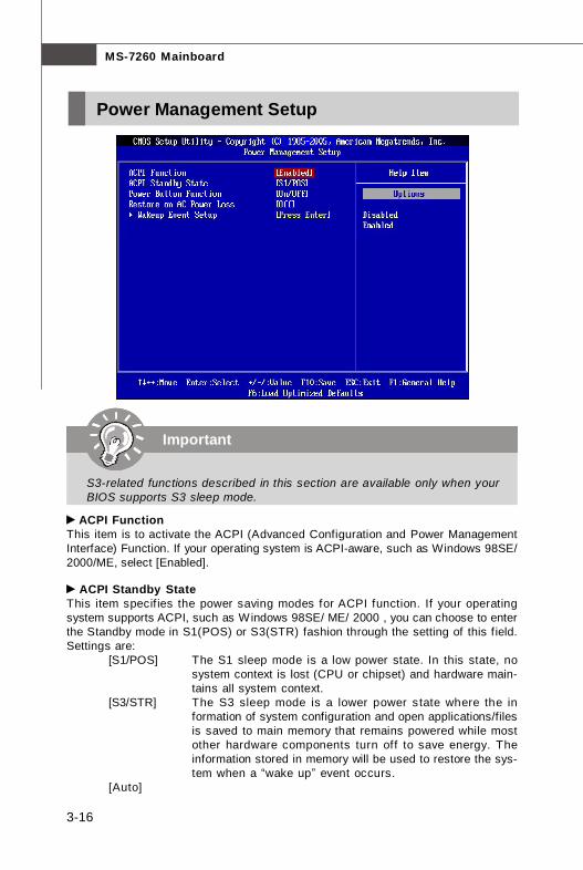
ACPI FunctionThis item is to activate the ACPI (Advanced Configuration and Power ManagementInterface) Function. If your operating system is ACPI-aware, such as Windows 98SE/2000/ME, select [Enabled].
ACPI Standby StateThis item specif ies the power saving modes for ACPI function. If your operatingsystem supports ACPI, such as Windows 98SE/ ME/ 2000 , you can choose to enterthe Standby mode in S1(POS) or S3(STR) fashion through the setting of this f ield.Settings are:
[S1/POS] The S1 sleep mode is a low power state. In this state, nosystem context is lost (CPU or chipset) and hardware main-tains all system context.
[S3/STR] The S3 sleep mode is a lower power state where the information of system configuration and open applications/filesis saved to main memory that remains powered while mostother hardware components turn off to save energy. Theinformation stored in memory will be used to restore the sys-tem when a “wake up” event occurs.
[Auto]
Power Management Setup
Important
S3-related functions described in this section are available only when yourBIOS supports S3 sleep mode.

BIOS Setup
3-17
Power Button FunctionThis feature sets the function of the power button. Settings are:
[On/ Off] The power button functions as normal power off button.[Suspend] When you press the power button, the computer enters the
suspend/sleep mode, but if the button is pressed for morethan four seconds, the computer is turned off.
Restore On AC Power LossThis item specifies whether your system will reboot after a power failure or interruptoccurs. Settings are:
[Off] Always leaves the computer in the power off state.[On] Always leaves the computer in the power on state.[Last State] Restores the system to the status before power failure
or interrupt occurred.
Wakeup Event SetupPress <Enter> and the following sub-menu appears.
Resume by PS/2 KeyboardThis controls how the PS/2 keyboard is able to power on the system. If youchoose Specific Key, the power button on the case will not function anymoreand you must type the password to power on the system.
Resume by PS/2 MouseThis setting determines whether the system will be awakened from what powersaving modes when input signal of the PS/2 mouse is detected.
Resume by MAC LANAn input signal on modem awakens the system from a soft off state.
Resume by PCI Device (PME#)When set to [Enabled], the feature allows your system to be awakened from thepower saving modes through any event on PME (Power Management Event).
Resume by PCIE DeviceWhen set to [Enabled], the feature allows your system to be awakened from thepower saving modes through any event on PCIE device.

MS-7260 Mainboard
3-18
Resume by RTC AlarmThe field is used to enable or disable the feature of booting up the system on ascheduled time/date.

BIOS Setup
3-19
Primary Graphics AdapterThis setting specifies which graphics card is your primary graphics adapter. Settingsare:
[PCIE] The system initializes the PCI Express graphics card that installed inPCIE x 16 slot first.
[PCI] The system initializes the PCI graphics card that installed in PCI slotf irst.
PCI Latency TimerThis item controls how long each PCI device can hold the bus before another takesover. When set to higher values, every PCI device can conduct transactions for alonger time and thus improve the effective PCI bandwidth. For better PCI performance,you should set the item to higher values.
PCI Slot 1/2/3 IRQThese items specify the IRQ line for each PCI slot.
PNP/PCI ConfigurationsThis section describes configuring the PCI bus system and PnP (Plug & Play) feature.PCI, or Peripheral Component Interconnect, is a system which allows I/O devices tooperate at speeds nearing the speed the CPU itself uses when communicating withits special components. This section covers some very technical items and it isstrongly recommended that only experienced users should make any changes to thedefault settings.

MS-7260 Mainboard
3-20
IRQ Resource SetupPress <Enter> to enter the sub-menu and the following screen appears.
IRQ 3/4/5/7/9/10/11/14/15These items specify the bus where the specified IRQ line is used.The settings determine if AMIBIOS should remove an IRQ from the pool of avail-able IRQs passed to devices that are configurable by the system BIOS. Theavailable IRQ pool is determined by reading the ESCD NVRAM. If more IRQs mustbe removed from the IRQ pool, the end user can use these settings to reservethe IRQ by assigning an [Reserved] setting to it. Onboard I/O is configured byAMIBIOS. All IRQs used by onboard I/O are configured as [Available]. If all IRQsare set to [Reserved], and IRQ 14/15 are allocated to the onboard PCI IDE, IRQ 9will still be available for PCI and PnP devices.
DMA Resource SetupPress <Enter> to enter the sub-menu and the following screen appears.
DMA Channel 0/1/3/5/6/7The settings determine if AMIBIOS should remove a DMA (Direct Memory Access)from the available DMAs passed to devices that are configurable by the systemBIOS. The available DMA pool is determined by reading the ESCD NVRAM. If moreDMAs must be removed from the pool, the end user can reserve the DMA.
Important
IRQ (Interrupt Request) lines are system resources allocated to I/O devices.When an I/O device needs to gain attention of the operating system, it sig-nals this by causing an IRQ to occur. After receiving the signal, when theoperating system is ready, the system will interrupt itself and perform theservice required by the I/O device.

BIOS Setup
3-21
CPU Spread SpectrumThis setting is used to enable or disable the CPU Spread Spectrum feature. Whenoverclocking the CPU, always set it to [Disabled].
PCIE Spread SpectrumThis setting is used to enable or disable the PCIE Spread Spectrum feature.
SATA Spread SpectrumThis setting is used to enable or disable the SATA Spread Spectrum feature.
Cool’n’QuietThis feature is especially desiged for AMD processor, which provides a CPU tem-perature detecting function to prevent your CPU’s from overheading due to the heavyworking loading.
H/W Monitor
Important
For the purpose of ensuring the stability of Cool'n'Quiet function, it is alwaysrecommended to have the memories plugged in DIMM1.

MS-7260 Mainboard
3-22
Chassis IntrusionThe field enables or disables the feature of recording the chassis intrusion statusand issuing a warning message if the chassis is once opened. To clear the warningmessage, set the field to [Reset]. The setting of the field will automatically return to[Enabled] later.
CPUFAN1 Mode SettingThis field allows you to set the CPU fan mode. Settings are: [Step Smart Fan], [ThermalCruise], [Disabled].
CPU Step Smart Fan Low/ High TempWhen the CPUFAN Mode Setting set to the “Step Smart Fan”, this item willapear. The mainboard provides another Smart Fan system which can control thefan speed automatically depending on the current temperature to keep it within aspecific step. In these items you can set the low and high tempertures, and thevalues between are the range of the steps.
CPUFAN1 Tolerance ValueWhen the CPUFAN Mode Setting set to the “Step Smart Fan”, this item willapear. The Fan tolerance value will decide the intervals of the steps from lowtemperature to high temperature. The fan speed will increase at higher stepsand decrease at lower steps according to the steps.
Current Smart Fan StepThis item shows how many steps between the low and high temperatures.Read only.
Each Step Increase Fan OutputThis item shows the percentage for the CPU fan speed to increase or decreasebetween two steps. Read only.
CPU Fan TargetTemp ValueWhen the CPUFAN Mode Setting set to the “Thermal Cruise” this item willappear. The mainboard provides the Smart Fan system which can control thefan speed automatically depending on the current temperature to keep it with ina specific range.
CPU Fan Tolerance ValueWhen the CPUFAN Mode Setting set to the “Thermal Cruise” this item willappear. You can select a fan tolerance value here for the specific range for the“CPU Fan TargetTemp. Value” item. If the current temperature of the fan reachesto the maximum threshold (the temperatures set in the “CPU Fan TargetTemp.Value” plus the tolerance values you set here), the fan will speed up for coolingdown. On the contrary, if the current temperature reaches to the minimumthreshold (the set temperatures minus the tolerance value), the fan will slowdown to keep the temperature stable.

BIOS Setup
3-23
PC Health StatusPress <Enter> to enter the sub-menu and the following screen appears.
System/ CPU Temperature, CPUFAN/System FAN Speed, CPU Vcore,+12.0V, +3.3V, +5.0V, 3VSBThese items display the current status of all of the monitored hardware devices/components such as CPU voltage, temperatures and all fans’ speeds.

MS-7260 Mainboard
3-24
Current CPU Clock/ Memory SpeedThese items show the current clocks of CPU and Memory speed. Read-only.
Adjust CPU FSB FrequencyThis item allows you to select the CPU Front Side Bus clock frequency (in MHz).
CPU Dynamic OverClockingDynamic Overclocking Technology is the automatic overclocking function, included inthe MSITM’s newly developed CoreCellTM Technology. It is designed to detect the loadbalance of CPU while running programs, and to adjust the best CPU frequencyautomatically. When the motherboard detects CPU is running programs, it will speedup CPU automatically to make the program run smoothly and faster. When the CPU istemporarily suspending or staying in the low load balance, it will restore the defaultsettings instead. Usually the Dynamic Overclocking Technology will be powered onlywhen users' PC need to run huge amount of data like 3D games or the video process,and the CPU frequency need to be boosted up to enhance the overall performance.Settings are:
Cell Menu
Important
Change these settings only if you are familiar with the chipset.
BIOS Setup
3-25
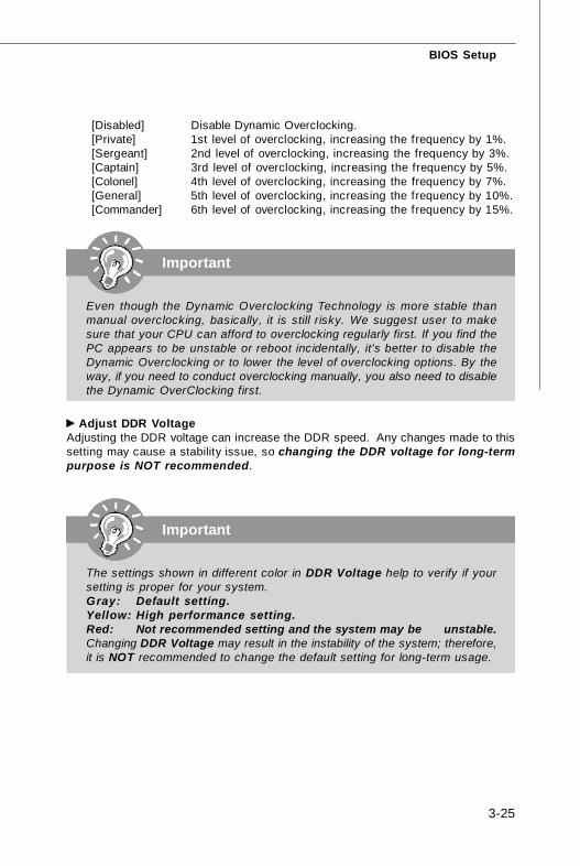
[Disabled] Disable Dynamic Overclocking.[Private] 1st level of overclocking, increasing the frequency by 1%.[Sergeant] 2nd level of overclocking, increasing the frequency by 3%.[Captain] 3rd level of overclocking, increasing the frequency by 5%.[Colonel] 4th level of overclocking, increasing the frequency by 7%.[General] 5th level of overclocking, increasing the frequency by 10%.[Commander] 6th level of overclocking, increasing the frequency by 15%.
Adjust DDR VoltageAdjusting the DDR voltage can increase the DDR speed. Any changes made to thissetting may cause a stability issue, so changing the DDR voltage for long-termpurpose is NOT recommended.
Important
Even though the Dynamic Overclocking Technology is more stable thanmanual overclocking, basically, it is still risky. We suggest user to makesure that your CPU can afford to overclocking regularly first. If you find thePC appears to be unstable or reboot incidentally, it's better to disable theDynamic Overclocking or to lower the level of overclocking options. By theway, if you need to conduct overclocking manually, you also need to disablethe Dynamic OverClocking first.
Important
The settings shown in different color in DDR Voltage help to verify if yoursetting is proper for your system.Gray: Default setting.Yellow: High performance setting.Red: Not recommended setting and the system may be unstable.Changing DDR Voltage may result in the instability of the system; therefore,it is NOT recommended to change the default setting for long-term usage.

MS-7260 Mainboard
3-26
The option on the main menu allows users to restore all of the BIOS settings to thedefault Optimized values. The Optimized Defaults are the default values set by themainboard manufacturer specifically for optimal performance of the mainboard.
When you select Load Optimized Defaults, a message as below appears:
Pressing Y loads the default factory settings for optimal system performance.
Load Optimized Defaults

BIOS Setup
3-27
BIOS Setting Password
When you select this function, a message as below will appear on the screen:
Type the password, up to six characters in length, and press <Enter>. The passwordtyped now will replace any previously set password from CMOS memory. You willbe prompted to confirm the password. Retype the password and press <Enter>. Youmay also press <Esc> to abort the selection and not enter a password.To clear a set password, just press <Enter> when you are prompted to enter thepassword. A message will show up confirming the password will be disabled. Oncethe password is disabled, the system will boot and you can enter Setup withoutentering any password.When a password has been set, you will be prompted to enter it every time you tryto enter Setup. This prevents an unauthorized person from changing any part of yoursystem configuration.

A-1
Realtek ALC883 Audio
Realtek ALC883 AudioAppendix A
The Realtek ALC883 provides 10-channel DAC that si-multaneously supports 7.1 sound playback and 2 chan-nels of independent s tereo sound output (multiplestreaming) through the Front-Out-Left and Front-Out-Right channels.

MS-7260 Mainboard
A-2
You need to install the driver for Realtek ALC883 codec to function properly beforeyou can get access to 2-, 4-, 6-, 8- channel or 7.1+2 channel audio operations.Follow the procedures described below to install the drivers for different operatingsystems.
Installation for Windows 2000/XPFor Windows® 2000, you must install Windows® 2000 Service Pack4 or later beforeinstalling the driver. For Windows® XP, you must install Windows® XP Service Pack1or later before installing the driver.The following illustrations are based on Windows® XP environment and could lookslightly different if you install the drivers in different operating systems.
1. Insert the application CD into the CD-ROM drive. The setup screen will auto-matically appear.
2. Click Realtek HD Audio Driver.
Installing the Realtek HD Audio Driver
Important
The HD Audio Configuration software utility is under continuous updateto enhance audio applications. Hence, the program screens shown here inthis section may be slightly different from the latest software utility and shallbe held for reference only.
Click here
A-3
Realtek ALC883 Audio
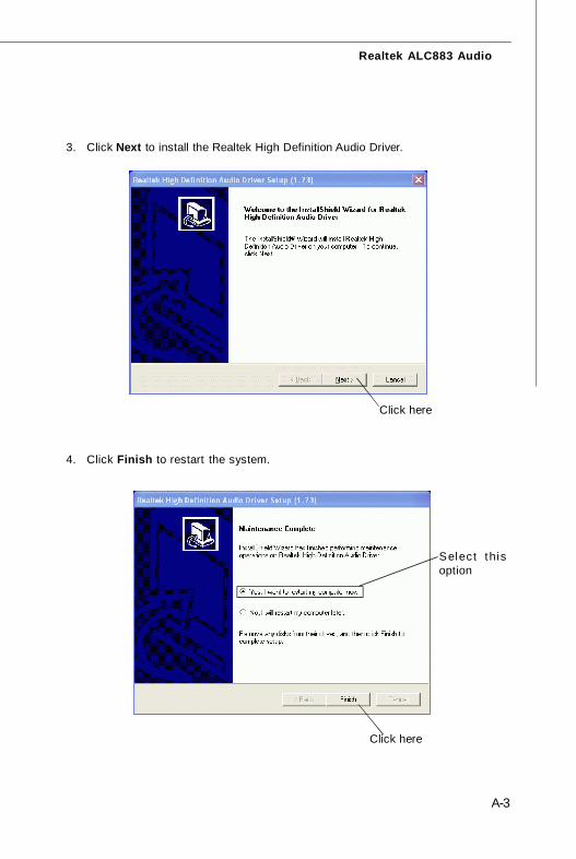
3. Click Next to install the Realtek High Definition Audio Driver.
Click here
Select thisoption
4. Click Finish to restart the system.
Click here
MS-7260 Mainboard
A-4
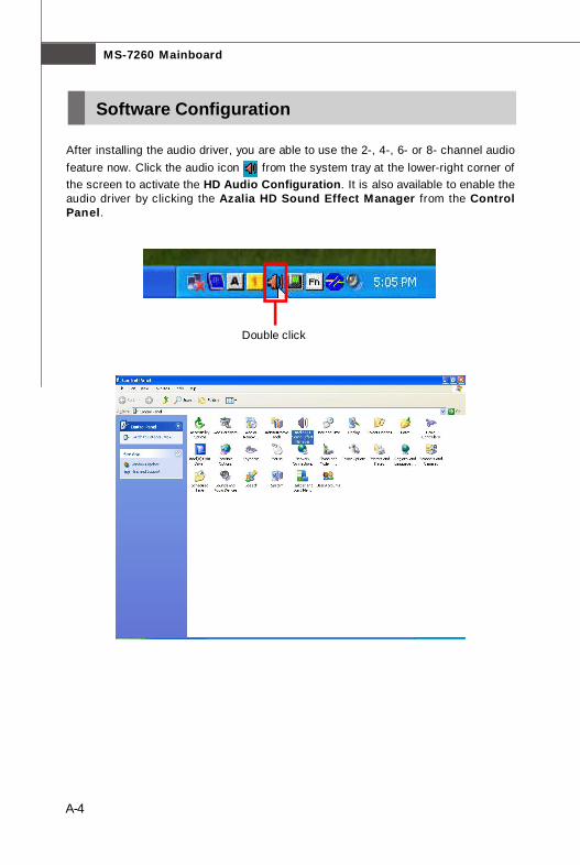
After installing the audio driver, you are able to use the 2-, 4-, 6- or 8- channel audiofeature now. Click the audio icon from the system tray at the lower-right corner ofthe screen to activate the HD Audio Configuration. It is also available to enable theaudio driver by clicking the Azalia HD Sound Effect Manager from the ControlPanel.
Double click
Software Configuration

A-5
Realtek ALC883 Audio
Sound Effect
Environment SimulationYou will be able to enjoy different sound experience by pulling down the arrow,totally 23 kinds of sound effect will be shown for selection. Realtek HD Audio SoundManager also provides five popular settings “Stone Corridor”, “Bathroom”, “Sewerpipe”, “Arena” and “Audio Corridor” for quick enjoyment.
You may choose the provided sound effects, and the equalizer will adjust automatically.If you like, you may also load an equalizer setting or make an new equalizer setting tosave as an new one by using the “Load EQ Setting” and “Save Preset” button,click “Reset EQ Setting” button to use the default value, or click “Delete EQ Set-ting” button to remove a preset EQ setting.
There are also other pre-set equalizer models for you to choose by clicking “Others”under the Equalizer part.
Here you can select a sound effect you like from the Environment list.

MS-7260 Mainboard
A-6
SaveThe settings are savedpermanently for futureuse
Reset10 bands of equalizerwould go back to the de-fault setting
Enable / DisableTo disable, you can tem-porarily s top the soundeffect without losing thesettings
LoadWhenever you would like touse preload settings, simplyclick this, the whole list willbe shown for your selection.
DeleteTo delete the pre-saved settings which are created from previous steps.
Equalizer SelectionEqualizer frees users from default settings; users may create their owned preferredsettings by utilizing this tool.
10 bands of equalizer, ranging from 100Hz to 16KHz.

A-7
Realtek ALC883 Audio
Raise the key
Lower the key
Remove thehuman voice
Frequently Used Equalizer SettingRealtek recognizes the needs that you might have. By leveraging our long experienceat audio field, Realtek HD Audio Sound Manager provides you certain optimized equal-izer settings that are frequently used for your quick enjoyment.
[How to Use It]Other than the buttons “Pop” “Live” “Club” & “Rock” shown on the page, to pull downthe arrow in “Others”, you will find more optimized settings available to you.
Karaoke ModeKaraoke mode brings Karaoke fun back home. Simply using the music you usuallyplay, Karaoke mode can help you eliminate the vocal of the song or adjust the key toaccommodate your range.1.Vocal Cancellation: Single click on “Voice Cancellation”, the vocal of the song would be eliminated, while the background music is still in place, and you can be that singer!2.Key Adjustment: Using “Up / Down Arrow” to find a key which better fits your vocal range.
MS-7260 Mainboard
A-8
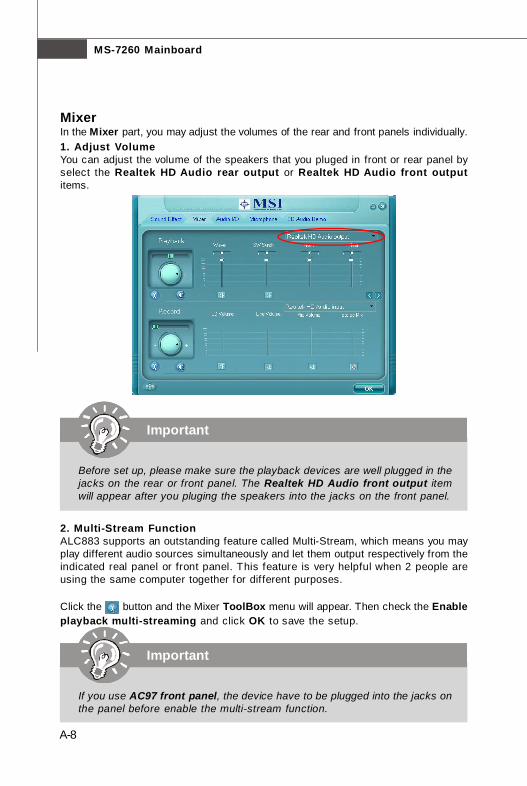
MixerIn the Mixer part, you may adjust the volumes of the rear and front panels individually.1. Adjust VolumeYou can adjust the volume of the speakers that you pluged in front or rear panel byselect the Realtek HD Audio rear output or Realtek HD Audio front outputitems.
2. Multi-Stream FunctionALC883 supports an outstanding feature called Multi-Stream, which means you mayplay different audio sources simultaneously and let them output respectively from theindicated real panel or front panel. This feature is very helpful when 2 people areusing the same computer together for different purposes.
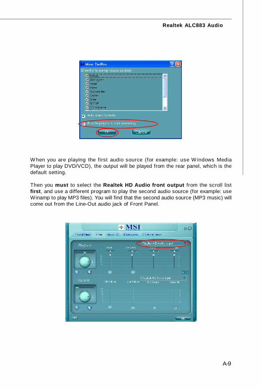
Click the button and the Mixer ToolBox menu will appear. Then check the Enableplayback multi-streaming and click OK to save the setup.
Important
Before set up, please make sure the playback devices are well plugged in thejacks on the rear or front panel. The Realtek HD Audio front output itemwill appear after you pluging the speakers into the jacks on the front panel.
Important
If you use AC97 front panel, the device have to be plugged into the jacks onthe panel before enable the multi-stream function.
A-9
Realtek ALC883 Audio
W hen you are playing the f irst audio source (for example: use W indows MediaPlayer to play DVD/VCD), the output will be played from the rear panel, which is thedefault setting.
Then you must to select the Realtek HD Audio front output from the scroll listfirst, and use a different program to play the second audio source (for example: useWinamp to play MP3 files). You will find that the second audio source (MP3 music) willcome out from the Line-Out audio jack of Front Panel.
MS-7260 Mainboard
A-10
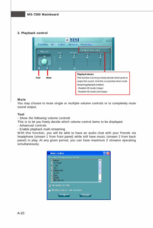
3. Playback control
Playback deviceThis function is to let you freely decide which ports tooutput the sound. And this is essential when multi-streaming playback enabled.- Realtek HD Audio Output- Realtek HD Audio 2nd Output
Tool Mute
MuteYou may choose to mute single or multiple volume controls or to completely mutesound output.
Tool- Show the following volume controlsThis is to let you freely decide which volume control items to be displayed.- Advanced controls- Enable playback multi-streamingW ith this function, you will be able to have an audio chat with your friends viaheadphone (stream 1 from front panel) while still have music (stream 2 from backpanel) in play. At any given period, you can have maximum 2 streams operatingsimultaneously.
A-11
Realtek ALC883 Audio
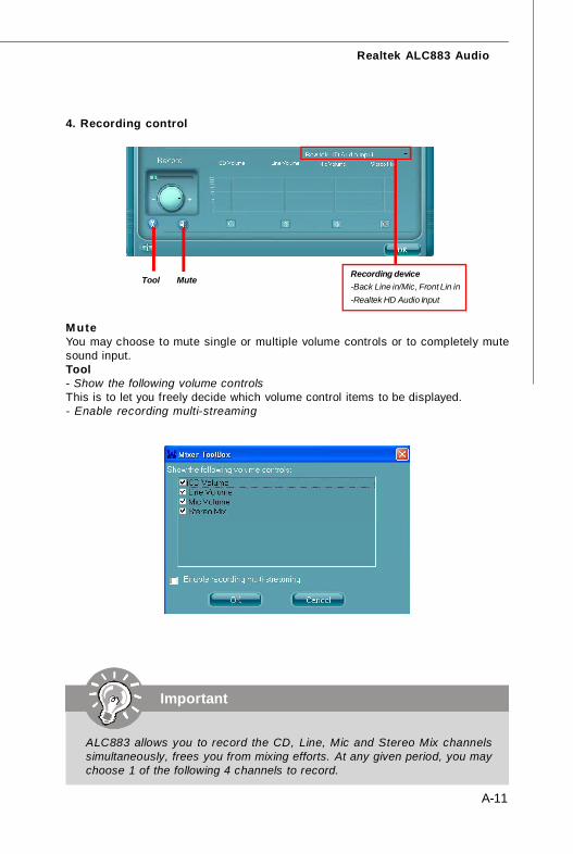
4. Recording control
Recording device-Back Line in/Mic, Front Lin in-Realtek HD Audio Input
MuteYou may choose to mute single or multiple volume controls or to completely mutesound input.Tool- Show the following volume controlsThis is to let you freely decide which volume control items to be displayed.- Enable recording multi-streaming
Tool Mute
Important
ALC883 allows you to record the CD, Line, Mic and Stereo Mix channelssimultaneously, frees you from mixing efforts. At any given period, you maychoose 1 of the following 4 channels to record.

MS-7260 Mainboard
A-12
Audio I/OIn this tab, you can easily configure your multi-channel audio function and speakers.You can choose a desired multi-channel operation here.
a. Headphone for the common headphoneb. 2CH Speaker for Stereo-Speaker Outputc. 4CH Speaker for 4-Speaker Outputd. 6CH Speaker for 5.1-Speaker Outpute. 8CH Speaker for 7.1-Speaker Output
Speaker Configuration:
1. Plug the speakers in the corresponding jack.
2. Dialogue “connected device” will pop up for your selection. Please select thedevice you have plugged in. - If the device is being plugged into the correct jack, you will be able to find the icon beside the jack changed to the one that is same as your device. - If not correct, Realtek HD Audio Manager will guide you to plug the device into the correct jack.
A-13
Realtek ALC883 Audio
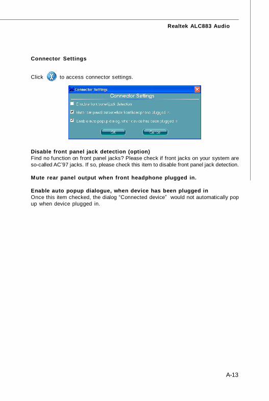
Connector Settings
Click to access connector settings.
Disable front panel jack detection (option)Find no function on front panel jacks? Please check if front jacks on your system areso-called AC’97 jacks. If so, please check this item to disable front panel jack detection.
Mute rear panel output when front headphone plugged in.
Enable auto popup dialogue, when device has been plugged inOnce this item checked, the dialog “Connected device” would not automatically popup when device plugged in.
MS-7260 Mainboard
A-14
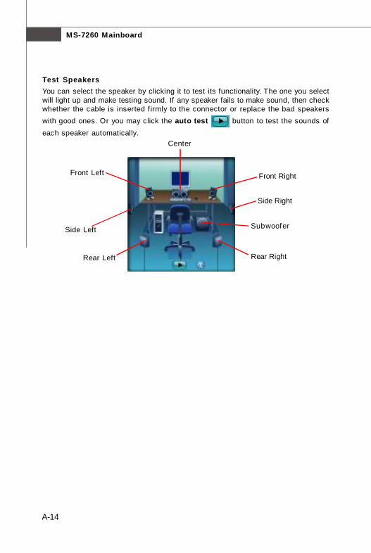
Test SpeakersYou can select the speaker by clicking it to test its functionality. The one you selectwill light up and make testing sound. If any speaker fails to make sound, then checkwhether the cable is inserted f irmly to the connector or replace the bad speakerswith good ones. Or you may click the auto test button to test the sounds ofeach speaker automatically.
Subwoofer
Front Right
Rear Right
Center
Front Left
Rear Left
Side Left
Side Right
A-15
Realtek ALC883 Audio
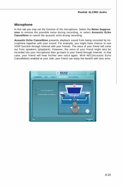
MicrophoneIn this tab you may set the function of the microphone. Select the Noise Suppres-sion to remove the possible noise during recording, or select Acoustic EchoCancelltion to cancel the acoustic echo druing recording.
Acoustic Echo Cancelltion prevents playback sound from being recorded by mi-crophone together with your sound. For example, you might have chance to useVOIP function through Internet with your friends. The voice of your friend will comeout from speakers (playback). However, the voice of your friend might also berecorded into your microphone then go back to your friend through Internet. In thatcase, your friend will hear his /her own voice again. W ith AEC(Acoustic EchoCancellation) enabled at your side, your friend can enjoy the benefit with less echo.
MS-7260 Mainboard
A-16
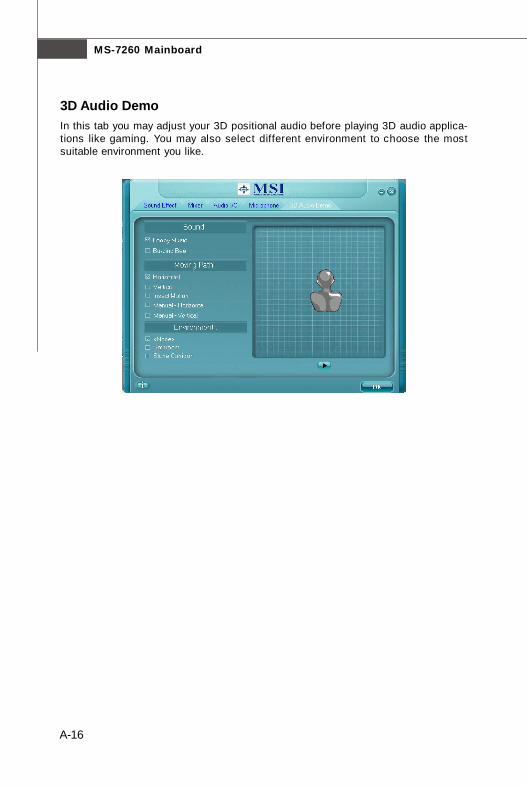
3D Audio DemoIn this tab you may adjust your 3D positional audio before playing 3D audio applica-tions like gaming. You may also select different environment to choose the mostsuitable environment you like.
A-17
Realtek ALC883 Audio
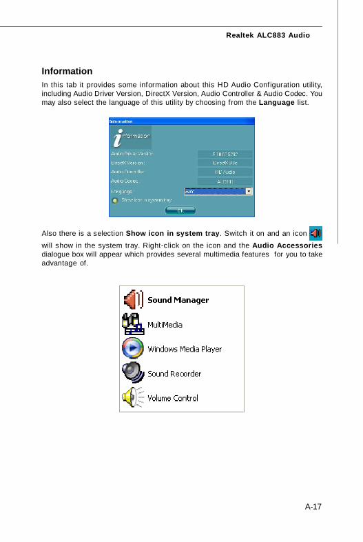
InformationIn this tab it provides some information about this HD Audio Configuration utility,including Audio Driver Version, DirectX Version, Audio Controller & Audio Codec. Youmay also select the language of this utility by choosing from the Language list.
Also there is a selection Show icon in system tray. Switch it on and an icon
will show in the system tray. Right-click on the icon and the Audio Accessoriesdialogue box will appear which provides several multimedia features for you to takeadvantage of.

MS-7260 Mainboard
A-18
Connecting the SpeakersWhen you have set the Multi-Channel Audio Function mode properly in the softwareutility, connect your speakers to the correct phone jacks in accordance with thesetting in software utility.
n 2-Channel Mode for Stereo-Speaker OutputRefer to the following diagram and caption for the function of each phone jack on theback panel when 2-Channel Mode is selected.
Back Panel
1 Line In2 Line Out (Front channels)3 MIC4 Line Out (Rear surround channels, but no functioning in this mode)5 Line Out (Center and Subwoofer channel, but no functioning in this mode)6 Line Out (Side surround channels, but no functioning in this mode)
Hardware Setup
3
1
2
6
4
5
A-19
Realtek ALC883 Audio
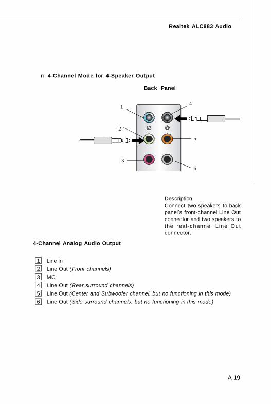
n 4-Channel Mode for 4-Speaker Output
Back Panel
Description:Connect two speakers to backpanel’s front-channel Line Outconnector and two speakers tothe real-channel L ine Outconnector.
4-Channel Analog Audio Output
1 Line In2 Line Out (Front channels)3 MIC4 Line Out (Rear surround channels)5 Line Out (Center and Subwoofer channel, but no functioning in this mode)6 Line Out (Side surround channels, but no functioning in this mode)
3
1
2
6
4
5
MS-7260 Mainboard
A-20
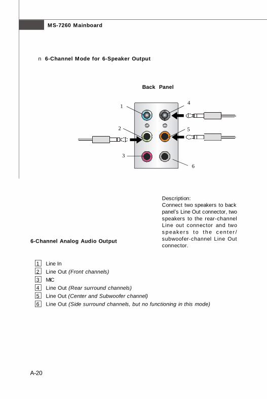
n 6-Channel Mode for 6-Speaker Output
Description:Connect two speakers to backpanel’s Line Out connector, twospeakers to the rear-channelLine out connector and twos p eaker s t o t h e c en t er /subwoofer-channel Line Outconnector.
6-Channel Analog Audio Output
1 Line In2 Line Out (Front channels)3 MIC4 Line Out (Rear surround channels)5 Line Out (Center and Subwoofer channel)6 Line Out (Side surround channels, but no functioning in this mode)
1
2
6
4
5
3
Back Panel

A-21
Realtek ALC883 Audio
n 8-Channel Mode for 8-Speaker Output
Description:Connect two speakers to backpanel’s Line Out connector, twospeakers to the rear-channelLine out connector, two speak-ers to the center/subwoofer-channel Line Out connector andtwo speakers to the side-chan-nel Line Out connector.
8-Channel Analog Audio Output
1 Side Surround Out (Side channels)2 Line Out (Front channels)3 MIC4 Line Out (Rear surround channels)5 Line Out (Center and Subwoofer channel)6 Line Out (Side channels)
1
2
6
4
5
3
B-1
nVidia RAID
nVidia RAIDAppendix B
NVIDIA brings Redundant Array of Independent Disks(RAID) technology—which is used by the world’s lead-ing businesses—to the common PC desktop. This tech-nology uses multiple drives to either increase total diskspace or to offer data protection. For all levels, RAIDtechniques optimize storage solutions by using multipledisks grouped together and treating them as a singlestorage resource.

MS-7260 Mainboard
B-2
Introduct ion
System Requirement
Operating System SupportNVRAID supports the following operating systems:
Windows XP
RAID ArraysNVRAID supports the following types of RAID arrays described in this section:RAID 0: RAID 0 defines a disk striping scheme that improves the disk read and writetimes for many applications.RAID 1: RAID 1 defines techniques for mirroring data.RAID 0+1: RAID 0+1 combines the techniques used in RAID 0 and RAID 1 arrays.Spanning (JBOD): JBOD provides a method for combining drives of different sizesinto one large disk
Summary of RAID Configurations
Array Uses Advantages Drawbacks # Hard Disks
Fault Tolerance
RAID 0 Non-critical data requiring high performance.
High data throughput. No fault tolerance. multiple None
RAID 1 Small databases or any other small capacity environment requiring fault tolerance.
100% data redundancy.
Requires 2 drives for the storage space of 1 drive.
2 Yes
RAID 0+1 Critical data requiring high performance.
Optimized for both 100% data redundancy and performance. Allows spare disks.
Requires 2 drives for the storage space of 1 drive—the same as RAID level 1.
4+ Yes
JBOD Combining odd size drives into one big drive
Combines and uses the capacity of odd size drives.
Decreases performance because of the difficulty in using drives concurrently or to optimize drives for different uses.
Multiple No

B-3
nVidia RAID
RAID Configuration
Basic Configuration InstructionsThe following are the basic steps for configuring NVRAID:
Non-Bootable RAID Array1. Choose the hard disks that are to be RAID enabled in the system BIOS. (To enablethe SATA 0/ 1 Primary/ Secondary Channel in nVidia RAID Setup of Inte-grated Peripherals in BIOS.)2. Specify the RAID level, either Mirroring (RAID 1), Striping (RAID 0), Striping and Mirroring (RAID 0+1) or JBOD and create the desired RAID array.3. Enter the Windows OS, run the Windows nForce Setup application and install the RAID software. (Check p.C-9 for details.)4. Initialize the NVRAID Array Disks.
Bootable RAID Array1. Choose the hard disks that are to be RAID enabled in the system BIOS. (To enablethe SATA 0/ 1 Primary/ Secondary Channel in nVidia RAID Setup of Inte-grated Peripherals in BIOS.)2. Specify the RAID level, either Mirroring (RAID 1), Striping (RAID 0), Striping andMirroring (RAID 0+1) or JBOD and create the desired RAID array.3. Boot from the Windows CD, use the floppy disk that has the RAID driver to copy and install the nForce RAID software. (Check p.C-7 for details.)4. Initialize the NVRAID Array Disks.
Setting Up the NVRAID BIOSBe sure to enable the SATA 0/ 1 Primary/ Secondary Channel in nVidia RAIDSetup of Integrated Peripherals in BIOS before configuring the NVRAID BIOS.After that press F10 to save the configuration and exit. The PC will reboot right away.Then enter the RAID BIOS Setup by pressing F10 when prompted, and follow theprocedures described below to set up the NVRAID BIOS.NVRAID BIOS setup lets you choose the RAID array type and which hard drives youwant to make part of the array.
Entering the RAID BIOS Setup1. After rebooting your PC, wait until you
see the RAID software prompting youto press F10. The RAID prompt ap-pears as part of the system POST andboot process prior to loading the OS.
2. Press F10, and the NVIDIA RAID Util-ity --- Define a New Array windowwill appear.The default RAID Mode is set to Mir-roring and Striping Block is set toOptimal .

MS-7260 Mainboard
B-4
Understanding the “Define a New Array” WindowUse the Define a New Array window to• Select the RAID Mode• Set up the Striping Block• Specify which disks to use for the RAID ArrayDepending on the platform used, the system can have one or more channels. In atypical system there is usually one controller and multiple channels, and each chan-nel has a slave and a master.The channel/controller/master/slave status of each hard disk is given in the Loc(location) columns of the Free Disks and Array Disks lists.
In the example above, 1.0.M means the hard drive is attached to Channel 2, Controller0, and the drive is set to Master. The following is a list of all possible combinations:
Serial ATA1.0.M Controller 1, Channel 0, Master (SATA1)1.1.M Controller 1, Channel 1, Master (SATA2)2.0.M Controller 2, Channel 0, Master (SATA3)2.1.M Controller 2, Channel 1, Master (SATA4)
Important
There is no such thing as Slave drive in Serial ATA. All drives are consideredto be Master since there is a one to one connection between the drive and thecontroller.

B-5
nVidia RAID
Using the Define a New Array WindowIf necessary, press the tab key to move from field to field until the appropriate field ishighlighted.
• Selecting the RAID ModeBy default, this is set to [Mirroring]. To change to a different RAID mode, press thedown arrow key until the mode that you want appears in the RAID Mode box—either[Mirroring], [Striping], [Spanning], or [Stripe Mirroring].
• Selecting the Striping Block SizeStriping Block size is given in kilobytes, and affects how data is arranged on thedisk. It is recommended to leave this value at the default [Optimal], which is 32KB, butthe values can be between [4 KB] and [128 KB].
• Assigning the DisksThe disks that you enabled from the RAID Config BIOS setup page appear in the FreeDisks block. These are the drives that are available for use as RAID array disks.To designate a free disk to be used as a RAID array disk,1. Tab to the Free Disks section. The first disk in the list is selected.2. Move it from the Free Disks block to the Array Disks block by pressing the right
arrow key (-->). The first disk in the list is moved, and the next disk in the list isselected and ready to be moved.
3. Continue pressing the right-arrow key (<-- ) until all the disks that you want to useas RAID array disks appear in the Array Disks block.
It shows that two disks have been assigned as RAID1 array disks in the f igureabove.
- Define a New Array -
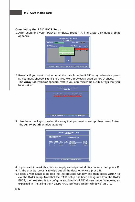
MS-7260 Mainboard
B-6
Completing the RAID BIOS Setup1. After assigning your RAID array disks, press F7. The Clear disk data prompt
appears.
2. Press Y if you want to wipe out all the data from the RAID array, otherwise pressN. You must choose Yes if the drives were previously used as RAID drives.The Array List window appears, where you can review the RAID arrays that youhave set up.
3. Use the arrow keys to select the array that you want to set up, then press Enter.The Array Detail window appears.
4. If you want to mark this disk as empty and wipe out all its contents then press C.5. At the prompt, press Y to wipe out all the data, otherwise press N.6. Press Enter again to go back to the previous window and then press Ctrl+X to
exit the RAID setup. Now that the RAID setup has been configured from the RAIDBIOS, the next step is to configure and load NVRAID drivers under W indows, asexplained in “Installing the NVIDIA RAID Software Under Windows” on C-9.

B-7
nVidia RAID
Installing the RAID Driver (for bootable RAID Array)1. After you complete the RAID BIOS setup, boot from the Windows CD, and the
Windows Setup program starts.2. Press F6 and wait for the Windows Setup screen to appear.
3. Specify the NVIDIA drivers:(1) Insert the floppy that has the RAID driver, press S, then press Enter. The
Windows Setup screen appears as below:
(2) Select “NVIDIA RAID CLASS DRIVER” and then press Enter.(3) Press S again at the Specify Devices screen, then press Enter.(4) Select “NVIDIA NForce Storage Controller” and then press Enter. The follow-
ing Windows Setup screen appears listing both drivers:
Important
Please follow the instruction below to make an nVIDIA Serial ATA RAID driverfor yourself.
1. Insert the MSI CD into the CD-ROM drive.2. Click the “Browse CD” on the Setup screen.3. Copy all the contents in the :\\nVidia \System \MCP55 \IDE \Win
XP\sataraid to a formatted floppy disk.4. The driver disk for nVIDIA RAID controller is done.

MS-7260 Mainboard
B-8
4. Press Enter to continue with Windows XP Installation. Be sure to leave the floppydisk inserted in the floppy drive until the blue screen portion of W indows XPinstallation is completed, then take out the floppy.
5. Follow the instructions on how to install Windows XP. After W indows XP is com-pletely installed, it is recommended that you install the the RAID management tool.
Important
Each time you add a new hard drive to a RAID array, the RAID driver will haveto be installed under Windows once for that hard drive. After that, the driverwill not have to be installed.

B-9
nVidia RAID
Installing the NVIDIA RAID Software Under Windows(for Non-bootable RAID Array)The existing Windows IDE Parallel ATA driver (as well as the Serial ATA driver if SATAis enabled) must be upgraded to use the NVIDIA IDE Parallel ATA driver (as well as theNV Serial ATA driver if SATA is enabled).This section describes how to run the setup application and install the RAID softwarewhich will upgrade the Windows IDE driver and install the RAID software.1. Start the NVIDIA nForce Drivers installation program to open the NVIDIA Windows
nForce Drivers page.
2. Select the modules that you want to install. Make sure that the “NVIDIA IDE Driver”is selected.
3. Click Next and then follow the instructions.4. After the installation is completed, be sure to reboot the PC.5. After the reboot, initialize the newly created array.
Important
You must install the NVIDIA IDE driver in order to enable NVIDIARAID. If you do not install the NVIDIA IDE driver, NVIDIA RAID will not beenabled.
NVIDIA IDE Drive/ RAID Utility Installation

MS-7260 Mainboard
B-10
Initializing and Using the Disk ArrayThe RAID array is now ready to be initialized under Windows.1. Launch Computer Management by clicking “Start” --> “Settings” --> “Control Panel”
then open the “Administrative Tools” folder and double click on “ComputerManagement”.
2. Click “Disk Management” (under the “Storage” section). The Initialize and ConvertDisk Wizards appears.
3. Click Next. The Select Disks to Initialize window appears. The disks listed dependon how many arrays you have configured.
4. Click Next. The Select Disks to Convert window appears.

B-11
nVidia RAID
5. Check the disk in the list if you want to make the array a dynamic disk, then clickNext. The Completing the Initialize and Convert Disk Wizard window appears.
6. Click Finish. The “Computer Management” window appears.
The actual disks listed will depend on your system, and the unallocated partition isthe total combined storage of two hard disks. You must format the unallocateddisk space in order to use it.
7. Format the unallocated disk space. Right click “Unallocated space”, select “NewPartition…” and follow the wizard. After the drive has been formatted, it is readyfor use.
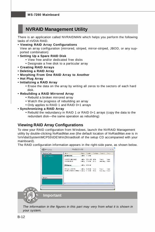
MS-7260 Mainboard
B-12
There is an application called NVRAIDMAN which helps you perform the followingtasks of nVDIA RAID.• Viewing RAID Array Configurations
View an array configuration (mirrored, striped, mirror-striped, JBOD, or any sup-ported combination)
• Setting Up a Spare RAID Disk• View free and/or dedicated free disks• Designate a free disk to a particular array
• Creating RAID Arrays• Deleting a RAID Array• Morphing From One RAID Array to Another• Hot Plug Array• Initializing a RAID Array
• Erase the data on the array by writing all zeros to the sectors of each hard disk.
• Rebuilding a RAID Mirrored Array• Rebuild a broken mirrored array• Watch the progress of rebuilding an array• Only applies to RAID 1 and RAID 0+1 arrays
• Synchronizing a RAID Array• Rebuild the redundancy in RAID 1 or RAID 0+1 arrays (copy the data to the
redundant disk—the same operation as rebuilding)
Viewing RAID Array ConfigurationsTo view your RAID configuration from Windows, launch the NVRAID Managementutility by double-clicking NvRaidMan.exe (the default location of NvRaidMan.exe is in\\nVidia\System\MCP55\IDE\Win2k\raidtool\ of the setup CD accompanied with yourmainboard).The RAID configuration information appears in the right-side pane, as shown below.
NVRAID Management Utility
Important
The information in the figures in this part may very from what it is shown inyour system.

B-13
nVidia RAID
Setting Up a Spare RAID DiskYou can designate a hard drive to be used as a spare drive for a RAID 1 or RAID 0+1array. The spare drive can take over for a failed disk. NVRAID supports two types ofspare drives:• Free DiskA free disk is a disk that is not part of any RAID array, but can be used by anyavailable RAID 1 or RAID 0+1 array that requires a particular disk when one of itsdisks crashes or becomes unusable. The process is automatic and doesn’t requireany user interaction.For example, if you have a system with four hard disks where one disk is used toboot the OS, two hard drives are set up in a mirrored array, and a fourth hard disk isset up as a free disk, then if one of the mirrored array drives fails, the free disk willbe automatically assigned to the mirrored array to be used instead of the failed disk.• Dedicated DiskA dedicated free disk is a disk that is assigned to a RAID 1 or RAID 0+1 array and thatdisk is used by that array only when needed, for example during a system crashwhere a RAID mirrored drive is broken. The dedicated disk can be used only by thearray that it is assigned to and not by any other array, unlike a free disk which can beused by any available RAID 1 or RAID 0+1 array.Note: You must have at least two RAID arrays to use this feature.
Assigning a Free DiskTo mark a disk as free, or not a part of any array,1. Enter the system BIOS setup and make sure that the drive that you want to mark as
free is RAID enabled.2. Enter the RAID BIOS and make sure that the drive is not part of any array (if one
exists).3. Boot into Windows and run the NVRAIDMAN program. The drive appears under the
Free Disk section. The figure below shows an example of the NVRAIDMAN displayif you have a mirror array and one free disk.

MS-7260 Mainboard
B-14
Assigning a Dedicated DiskTo mark a disk as dedicated, or reserve it for use by a specif ic array,
Step 1: Mark the Disk as a Free Disk1. Enter the system BIOS setup and make sure that the drive that you want to mark as
free is RAID enabled.2. Boot into Windows and run the NVRAIDMAN program.If the disk is not part of any RAID array, then it will appear under the Free Disksection of the RAID GUI.
Step 2: Dedicate the Free Disk to an ArrayWhile running NVRAIDMAN, dedicate the free disk to an array by doing the following:
1. Right click one of the two Mirrored arrays as shown below.
2. Select Designate Spare from the menu to launch the Spare Disk Allocation Wizard.

B-15
nVidia RAID
3. Click Next.The RAID Array Selection page appears.
4. From the Free Disk Selection page, select one of the two free disks available.This would be the disk that will be designated to the mirror array.
5. Click Next.The Completing the NVIDIA Spare Disk Allocation page appears.
6. Click Finish.As shown in figure below, the ST380011A drive is now a dedicated free disk in themirrored array. If a system crash occurs that causes any of the two WD360GDdrives to fail, the ST380011A hard drive will take over and be used in the newlyformed mirrored array.

MS-7260 Mainboard
B-16
Removing a Dedicated DiskOnce a dedicated disk has been assigned to a particular array, it can be removed atany time. To remove the disk, right click on the dedicated disk and select “RemoveDisk...” to remove it. In the previous example, simply right click on the ST380011Adrive and select “Remove Disk...”. as shown in the screen shot below:
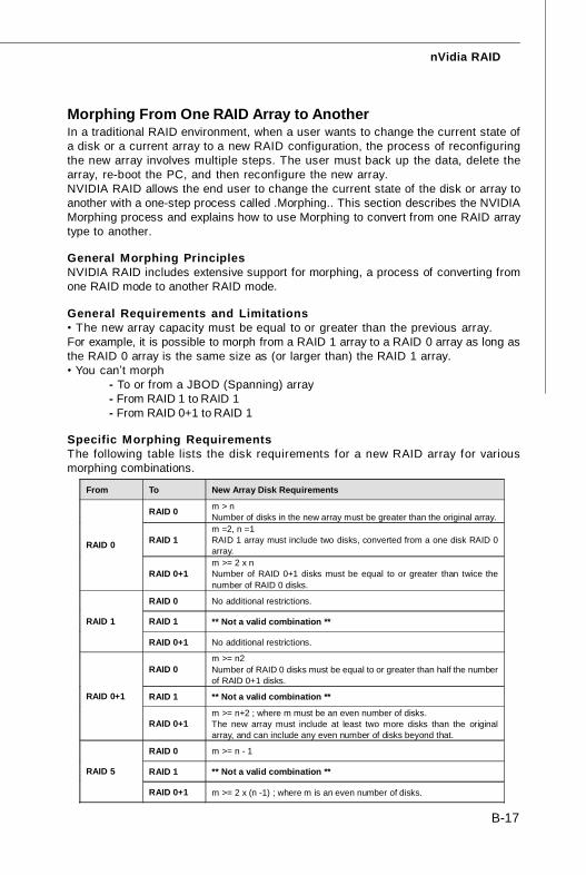
B-17
nVidia RAID
Morphing From One RAID Array to AnotherIn a traditional RAID environment, when a user wants to change the current state ofa disk or a current array to a new RAID configuration, the process of reconfiguringthe new array involves multiple steps. The user must back up the data, delete thearray, re-boot the PC, and then reconfigure the new array.NVIDIA RAID allows the end user to change the current state of the disk or array toanother with a one-step process called .Morphing.. This section describes the NVIDIAMorphing process and explains how to use Morphing to convert from one RAID arraytype to another.
General Morphing PrinciplesNVIDIA RAID includes extensive support for morphing, a process of converting fromone RAID mode to another RAID mode.
General Requirements and Limitations• The new array capacity must be equal to or greater than the previous array.For example, it is possible to morph from a RAID 1 array to a RAID 0 array as long asthe RAID 0 array is the same size as (or larger than) the RAID 1 array.• You can’t morph
- To or from a JBOD (Spanning) array- From RAID 1 to RAID 1- From RAID 0+1 to RAID 1
Specific Morphing RequirementsThe following table lists the disk requirements for a new RAID array for variousmorphing combinations.
From To New Array Disk Requirements
RAID 0 m > n Number of disks in the new array must be greater than the original array.
RAID 1 m =2, n =1 RAID 1 array must include two disks, converted from a one disk RAID 0 array.
RAID 0
RAID 0+1 m >= 2 x n Number of RAID 0+1 disks must be equal to or greater than twice the number of RAID 0 disks.
RAID 0 No additional restrictions.
RAID 1 ** Not a valid combination ** RAID 1
RAID 0+1 No additional restrictions.
RAID 0 m >= n2 Number of RAID 0 disks must be equal to or greater than half the number of RAID 0+1 disks.
RAID 1 ** Not a valid combination ** RAID 0+1
RAID 0+1 m >= n+2 ; where m must be an even number of disks. The new array must include at least two more disks than the original array, and can include any even number of disks beyond that.
RAID 0 m >= n - 1
RAID 1 ** Not a valid combination ** RAID 5
RAID 0+1 m >= 2 x (n -1) ; where m is an even number of disks.
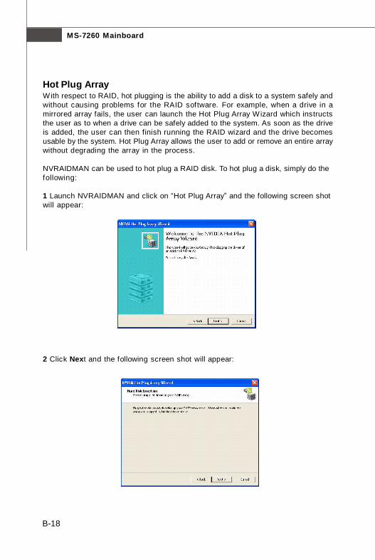
MS-7260 Mainboard
B-18
Hot Plug ArrayWith respect to RAID, hot plugging is the ability to add a disk to a system safely andwithout causing problems for the RAID software. For example, when a drive in amirrored array fails, the user can launch the Hot Plug Array Wizard which instructsthe user as to when a drive can be safely added to the system. As soon as the driveis added, the user can then finish running the RAID wizard and the drive becomesusable by the system. Hot Plug Array allows the user to add or remove an entire arraywithout degrading the array in the process.
NVRAIDMAN can be used to hot plug a RAID disk. To hot plug a disk, simply do thefollowing:
1 Launch NVRAIDMAN and click on “Hot Plug Array” and the following screen shotwill appear:
2 Click Next and the following screen shot will appear:
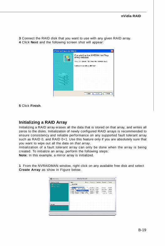
B-19
nVidia RAID
3 Connect the RAID disk that you want to use with any given RAID array.4 Click Next and the following screen shot will appear:
5 Click Finish.
Initializing a RAID ArrayInitializing a RAID array erases all the data that is stored on that array, and writes allzeros to the disks. Initialization of newly configured RAID arrays is recommended toensure consistency and reliable performance on any supported fault tolerant arraysuch as RAID 0, and RAID 0+1. Use this feature only if you are absolutely sure thatyou want to wipe out all the data on that array.Initialization of a fault tolerant array can only be done when the array is beingcreated. To initialize an array, perform the following steps:Note: In this example, a mirror array is initialized.
1 From the NVRAIDMAN window, right click on any available free disk and selectCreate Array as show in Figure below.
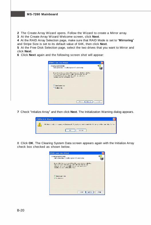
MS-7260 Mainboard
B-20
2 The Create Array Wizard opens. Follow the Wizard to create a Mirror array.3 At the Create Array Wizard Welcome screen, click Next.4 At the RAID Array Selection page, make sure that RAID Mode is set to “Mirroring”and Stripe Size is set to its default value of 64K, then click Next.5 At the Free Disk Selection page, select the two drives that you want to Mirror andclick Next.6 Click Next again and the following screen shot will appear:
7 Check “Intialize Array” and then click Next. The Initialization Warning dialog appears.
8 Click OK. The Clearing System Data screen appears again with the Initialize Arraycheck box checked as shown below.
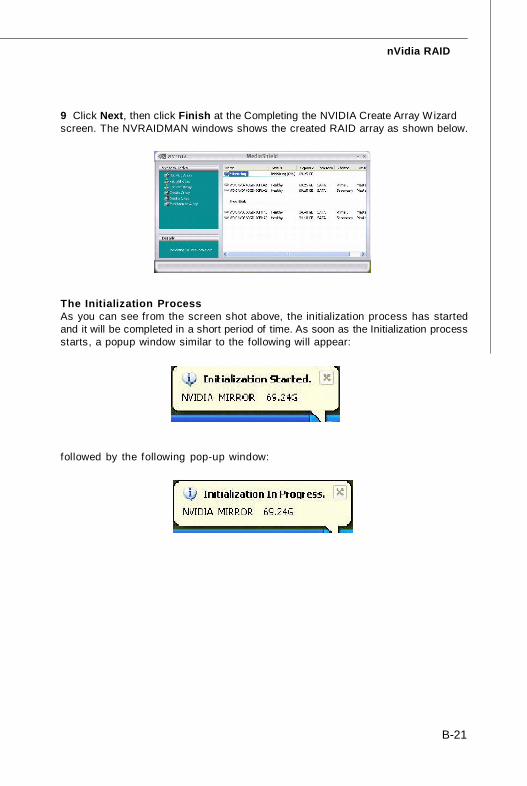
B-21
nVidia RAID
9 Click Next, then click Finish at the Completing the NVIDIA Create Array Wizardscreen. The NVRAIDMAN windows shows the created RAID array as shown below.
The Initialization ProcessAs you can see from the screen shot above, the initialization process has startedand it will be completed in a short period of time. As soon as the Initialization processstarts, a popup window similar to the following will appear:
followed by the following pop-up window:
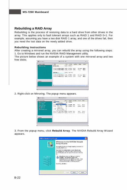
MS-7260 Mainboard
B-22
Rebuilding a RAID ArrayRebuilding is the process of restoring data to a hard drive from other drives in thearray. This applies only to fault tolerant arrays such as RAID 1 and RAID 0+1. Forexample, assuming you have a two disk RAID 1 array, and one of the drives fail, thenyou need the lost data on the newly added drive.
Rebuilding InstructionsAfter creating a mirrored array, you can rebuild the array using the following steps:1. Go to Windows and run the NVIDIA RAID Management utility.The picture below shows an example of a system with one mirrored array and twofree disks.
2. Right-click on Mirroring. The popup menu appears.
3. From the popup menu, click Rebuild Array. The NVIDIA Rebuild Array W izardappears.

B-23
nVidia RAID
4. Click Next. The Disk Selection page appears.
5. Select the drive that you want to rebuild by clicking it from the list, then click Next.The Completing the NVIDIA Rebuild Array page appears.
6. Click Finish. The array rebuilding starts after a few seconds, and a small pop-upmessage appears towards the bottom right corner of the screen as shown in thefigure below.
When the rebuilding process is finished you will see the pop up box shown in Figurebelow.

MS-7260 Mainboard
B-24
During the rebuilding process, the NVRAID Management utility screen shows thestatus under the System Tasks and Details sections.
More About Rebuilding Arrays• Rebuilding Occurs in the BackgroundThe rebuilding process is very slow (it can take up to a day) and occurs in thebackground so as not to affect the performance of the system.• Rebuilding Applies Only to RAID 1 or RAID 0+1 ArraysRebuilding an array works only when using RAID 1 or RAID 0+1. Rebuildingdoes not apply to RAID 0 and JBOD arrays.• Rebuilding applies to a degraded fault tolerant arrayYou can rebuild a degraded mirrored array using any available Free Disk or DedicatedDisk. For example, Figure below shows a mirrored array using two 34.48 GB driveswhile having two Free Disks each 55.90 GB large.
To use one of these available free disks to rebuild your array, follow the same stepsas explained in “Rebuilding a RAID Array” on C-22, except when prompted to selecta disk, choose one of the two available free disks.

B-25
nVidia RAID
Synchronizing a RAID ArraySynchronizing an array will force a rebuild of redundancy or parity. The operation isapplicable to any fault tolerant array such as RAID 1 and RAUD 0+1.• For RAID1 and RAID 0+1, “sync” results in copying the data to the redundancy disk,
To sync an array, do the following (This example assumes you have already createda fault tolerant array such as RAID 1):1. Right click on “Mirroring” and select Synchronize Array as shown in Figurebelow.
2. The Synchronize Array Wizard Welcome screen appears.
3. Click on Next and then click Finish at the W izard Completion screen. TheNVRAIDMAN window indicates that the array is synchronizing, as shown in Figurebelow.
As you can see from the screen shot above, the synchronization process hasstarted and it will be completed in a short period of time.

C-1
Installation of nVidia System Driver
nVidia System DriverAppendix C
MSI provides a setup CD along with your mainboard,which contains the required drivers for your system,and many other useful and powerful utility to bring youthe best experience for your office professional work-ing and for your home leisure entertainment.
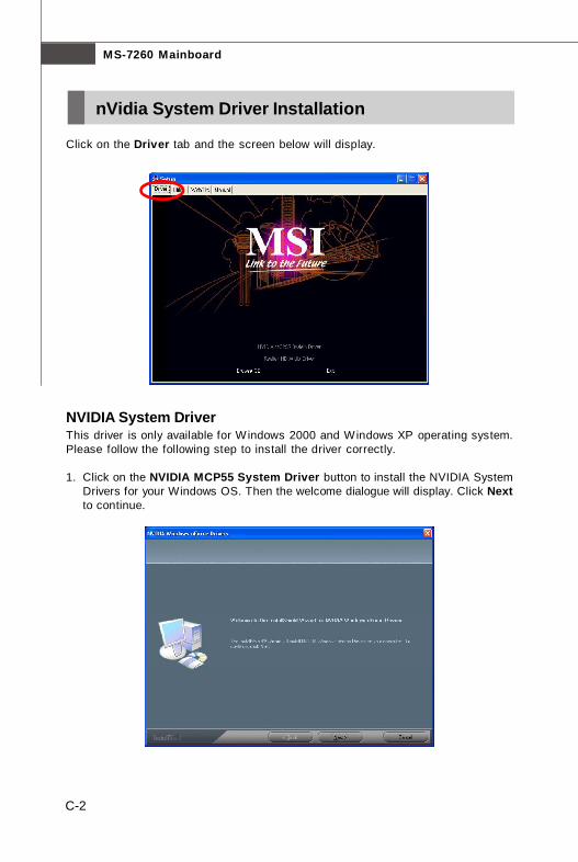
MS-7260 Mainboard
C-2
Click on the Driver tab and the screen below will display.
NVIDIA System DriverThis driver is only available for Windows 2000 and Windows XP operating system.Please follow the following step to install the driver correctly.
1. Click on the NVIDIA MCP55 System Driver button to install the NVIDIA SystemDrivers for your Windows OS. Then the welcome dialogue will display. Click Nextto continue.
nVidia System Driver Installation
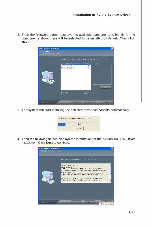
C-3
Installation of nVidia System Driver
2. Then the following screen displays the available components to install. All thecomponents shown here will be selected to be installed by default. Then clickNext.
3. The system will start installing the selected driver components automatically.
4. Then the following screen displays the information for the NVIDIA IDE SW Driverinstallation. Click Next to continue.

MS-7260 Mainboard
C-4
5. Then the following screen displays the installation of NVIDIA IDE SW Driver. ClickYes to continue.
6. The following screen indicates that the installation is complete. Click Yes to restartyour computer or click No to restart it later.

C-5
Installation of nVidia System Driver
1. Click on the Utility tab and the screen below will display.
2. Then click on the NVIDIA Utility tab and the screen below will display.
3. Click the nTune Utility icon to install it.
NVIDIA nTune Utility - provides a safe and easy way to optimize PC performance.
nVidia Utility Installation


