Page 1
261P-1264-WE • 4/11 Warner Electric • 800-234-3369
Clutch and Brake Controls . . . . . . . . . . . . . . . . . . . . . . . . . . . . . . . 262
On-Off Controls
CBC-100 . . . . . . . . . . . . . . . . . . . . . . . . . . . . . . . . . . . . . . . . . 264
CBC-150 . . . . . . . . . . . . . . . . . . . . . . . . . . . . . . . . . . . . . . . . . 264
CBC-160 . . . . . . . . . . . . . . . . . . . . . . . . . . . . . . . . . . . . . . . . . 265
CBC-801 . . . . . . . . . . . . . . . . . . . . . . . . . . . . . . . . . . . . . . . . . 266
CBC-802 . . . . . . . . . . . . . . . . . . . . . . . . . . . . . . . . . . . . . . . . . 267
CBC-400 . . . . . . . . . . . . . . . . . . . . . . . . . . . . . . . . . . . . . . . . . 268
CBC-450 . . . . . . . . . . . . . . . . . . . . . . . . . . . . . . . . . . . . . . . . . 269
Adjustable Torque Controls
MCS-103-1 . . . . . . . . . . . . . . . . . . . . . . . . . . . . . . . . . . . . . . . 270
MCS-153 . . . . . . . . . . . . . . . . . . . . . . . . . . . . . . . . . . . . . . . . . 271
CBC-200 . . . . . . . . . . . . . . . . . . . . . . . . . . . . . . . . . . . . . . . . . 272
CBC-300 . . . . . . . . . . . . . . . . . . . . . . . . . . . . . . . . . . . . . . . . . 272
CBC-500 . . . . . . . . . . . . . . . . . . . . . . . . . . . . . . . . . . . . . . . . . 273
CBC-550 . . . . . . . . . . . . . . . . . . . . . . . . . . . . . . . . . . . . . . . . . 274
CBC-1825R . . . . . . . . . . . . . . . . . . . . . . . . . . . . . . . . . . . . . . . 276
Overexcitation Controls
CBC-700 . . . . . . . . . . . . . . . . . . . . . . . . . . . . . . . . . . . . . . . . . 277
CBC-750 . . . . . . . . . . . . . . . . . . . . . . . . . . . . . . . . . . . . . . . . . 278
Closed Loop Position Control
CBC-1000 . . . . . . . . . . . . . . . . . . . . . . . . . . . . . . . . . . . . . . . . 280
Appendix . . . . . . . . . . . . . . . . . . . . . . . . . . . . . . . . . . . . . . . . . . . . 282
Questions & Answers . . . . . . . . . . . . . . . . . . . . . . . . . . . . . . . . . . 283
Warner Electric’s electronic controls are
designed to provide simple setup and
maximum performance when used with
electric clutches and brakes. Our controls
offer a range of functions from on-off to
torque control to over-excitation.
Selection
Many parameters beyond function can
impact control selection. Warner Electric
produces a variety of control options to
suit numerous application requirements.
Control selection parameters include:
• Mounting Location – Panel or conduit
box mounting
• Switching – Relay switching of A.C. or
D.C. lines or solid state switching
• Output Voltage – Controls are available
for 6, 24 and 90 VDC clutch/brake coils
• Input Voltage – Controls with input
power transformers are available for
connection to high voltage mains.
If your application requires something
special, please call us. We will be happy
to provide solutions.
Clutch and Brake Controls
Contents
KALATEC AUTOMAÇÃO LTDA
CAMPINAS (19)3045-4900 SAO PAULO(11)5514-7680 JOINVILLE(47)3425-0042
Page 2
Control
Type
On-OffConduit BoxMount
On-Off
Octal Socket
Mount
On-Off
Panel Mount
Adjustable
Torque
Adjustable Accel-Decel
Overexcitation
Position Loop
262 Warner Electric • 800-234-3369 P-1264-WE • 4/11
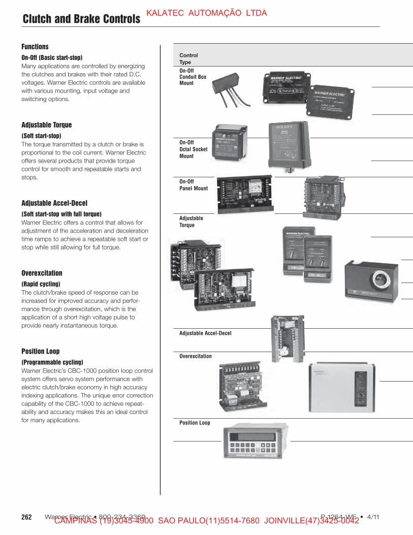
Functions
On-Off (Basic start-stop)
Many applications are controlled by energizing
the clutches and brakes with their rated D.C.
voltages. Warner Electric controls are available
with various mounting, input voltage and
switching options.
Adjustable Torque
(Soft start-stop)
The torque transmitted by a clutch or brake is
proportional to the coil current. Warner Electric
offers several products that provide torque
control for smooth and repeatable starts and
stops.
Adjustable Accel-Decel
(Soft start-stop with full torque)
Warner Electric offers a control that allows for
adjustment of the acceleration and deceleration
time ramps to achieve a repeatable soft start or
stop while still allowing for full torque.
Overexcitation
(Rapid cycling)
The clutch/brake speed of response can be
increased for improved accuracy and perfor-
mance through overexcitation, which is the
application of a short high voltage pulse to
provide nearly instantaneous torque.
Position Loop
(Programmable cycling)
Warner Electric’s CBC-1000 position loop control
system offers servo system performance with
electric clutch/brake economy in high accuracy
indexing applications. The unique error correction
capability of the CBC-1000 to achieve repeat-
ability and accuracy makes this an ideal control
for many applications.
Clutch and Brake ControlsKALATEC AUTOMAÇÃO LTDA
CAMPINAS (19)3045-4900 SAO PAULO(11)5514-7680 JOINVILLE(47)3425-0042
Page 3
Torque A.C. D.C. Customer Supplied
Model No. of Control Input Output Over- Switching Page
Number Channels Channels Voltages Voltages Excitation Options Description Number
CBC-100-1 1 No 120 90 No Relay A.C. Single channel control toCBC-100-2 1 No 220/240 mount inside standard 264
conduit box
CBC-150-1 2 No 120 90 No Relay A.C. Dual channel controlCBC-150-2 2 No 220/240 for clutch/brake to 264
mount inside moduleconduit box
CBC-160-1 120 Single channel control with
CBC-160-2 1 1 220/240 90 No Relay A.C. torque adjust for module 265
electrically released brakes
CBC-801-1 2 No 120 90 No Relay D.C. Dual channel control for
CBC-801-2 2 220/240 2 clutches and/or brakes 266
CBC-802 2 No 120 90 No Transistor or Dual channel control with
Relay D.C. transistor switching 267
CBC-400-90 2 No 120 90 No Dual channel control for
CBC-400-24 2 No 24-30 24 No Transistor or use with 2 clutches 268
CBC-450-90 2 No 120/220/240/380/480 90 No Relay D.C. and/or brakes;
CBC-450-24 2 No 120/220/240/380/480 24 No Emergency stop input
and AUX power supply
MCS-103-1 2 1 120 90 No Relay D.C. Dual channel control
with torque adjust 270
for one channel
MCS-805-1 1 1 120/240 35-75 No Relay D.C. Single adjustable channel
MCS-805-2 control for use with 271
ER 1225 brake
CBC-200 2 1 120 90 No Transistor or Dual channel control with
Relay D.C. one adjustable current 272
and one fixed voltage
CBC-300 2 2 120 90 No Transistor or Dual channel adjustable 272
Relay D.C. current control
CBC-500-90 2 2 120 90 No Dual channel control for two
CBC-500-24 2 2 24-30 24 No Transistor or clutches and/or brakes with 273
CBC-550-90 2 2 120/220/240/380/480 90 No Relay D.C. two torque adjust channels;
CBC-550-24 2 2 120/220/240/380/480 24 No Emergency stop input
CBC-1825-R 2 2 120 90 No Transistor or Dual channel adjustable
Relay D.C. time ramp with short 276
circuit protection
CBC-700-90 2 No 120 90 Yes Transistor or Dual channel compact
CBC-700-24 2 24–28 24 Relay D.C. overexcitation control for 277
24 or 90 volt clutches
and brakes
CBC-750-6-24-90 2 2 120/220/240 6,24,90 Yes Transistor, Dual channel full function
Relay D.C. or overexcitation control; 278
Triac A.C. provides input/output logic,
torque adjustable current
and remote inputs
CBC-1000 2 N.A. 120/230 N.A. N.A. N.A. Error correction control
to be used with one of 280
the above
263P-1264-WE • 4/11 Warner Electric • 800-234-3369
Clutch and Brake ControlsKALATEC AUTOMAÇÃO LTDA
CAMPINAS (19)3045-4900 SAO PAULO(11)5514-7680 JOINVILLE(47)3425-0042
Page 4
264 Warner Electric • 800-234-3369 P-1264-WE • 4/11
Specifications
CBC-100-1 CBC-100-2 CBC-150-1 CBC-150-2
Part No. 6003-448-101 6003-448-103 6004-448-001 6004-448-002
Input 120 VAC 220/240 VAC 120 VAC 220/240 VAC50/60 Hz 50/60 Hz 50/60 Hz 50/60 Hz
Output 90 VDC full wave 90 VDC half wave 90 VDC full wave 90 VDC half waverectified rectified.8 Amp max. .8 Amp Dual .8 Amp Dual .8 Amp
Ambient
Temperatures -20° to 113°F (-29° to 45°C)
Switching External to control, accomplished on A.C. line using relay or triac.
SPST SPST SPDT SPDT
Solid State
(maximum 140 VAC, 280 VAC, 140 VAC, 280 VAC,
leakage 1 Amp min. 1 Amp min. 2 Amp min. 2 Amp min.
current <2 mA)
Electro- 120 VAC, 240 VAC, 120 VAC, 240 VAC,
mechanical 1 Amp min. 1 Amp min. 1 Amp min. 1 Amp min.
Connection diagrams
CBC-100-1, -2
CBC-150-1, -2
Dimensions
CBC-100-1, -2
CBC-150-1, -2
All dimensions nominal unless
otherwise specified.
The CBC-100 and CBC-150 series are
UL listed, conduit box mounted controls
for 90 volt clutches and brakes. Models
are available for either 120 VAC or
220/240 VAC input.
FUSE SWITCHBLACK/REDHOT
CBC-100-1120 VAC
CBC-100-2220/240 VAC
NEUTRAL
USER FURNISHED
WHITE
CBC-100
RED
RED/WHITE
90VOLT
2.18" MAX. 1.34"MAX.
0.625"
0.166" DIA.MOUNTING HOLEFOR #6 SCREW
0.625"
CBC-150-1120 VAC
CBC-150-2220/240 VAC
HOT
FUSE SWITCH BLACK/RED
CBC-150-1,-2
RED
NEUTRAL
USER FURNISHEDWHITE RED/WHITE
BLACK/BLUE
CHANNEL 1
(BLUE)
BLUE/WHITE
BLUE
CHANNEL 2
(RED)
90 VOLTCLUTCH
OR BRAKE
+-
-+
2.88"
3.3" MAX.
1.80"
2.20"
0.22" MIN.4 HOLES
0.56" MAX.
.15"
CBC-150 series
Dual channel capacity
The CBC-150 replaces the cover
on the standard module conduit
box (part no. 5370-101-042).
Provides rectification and suppres-
sion for two devices. Green LED
indicates power to clutch. Red
LED indicates power to brake.
•
• and
• Dual channel
• Replaces the cover on the
module conduit box
®UL
CBC-100 series
Single unit capacity
The CBC-100 mounts inside a
standard Warner Electric conduit
box and includes rectification and
suppression circuits.
•
• and
•
• Compact
• Single channel
• Mounts inside conduit box
®UL
CBC-100, CBC-150 On-Off Controls
Integral/Conduit Box Mounted Controls
KALATEC AUTOMAÇÃO LTDA
CAMPINAS (19)3045-4900 SAO PAULO(11)5514-7680 JOINVILLE(47)3425-0042
Page 5
265P-1264-WE • 4/11 Warner Electric • 800-234-3369
0.56"
.15"
2.2"
1.8"
0.22" , 4 HOLES
2.88"
3.30"
Connection Diagram
Dimensions
All dimensions nominal unless otherwise specified.
•
•
CBC-160-1
90 VDCBRAKE
+
-0 100
50
RED
RED/WHITE
460 VAC
•
•
CBC-160-2
230 VAC 90 VDCBRAKE
+
-0 100
50
230 VAC
•
•
CBC-160-2
230 VAC90 VDCBRAKE
+
-0 100
50
460 VAC
•
•
CBC-160-2
230 VAC 90 VDCBRAKE
+
-0 100
50
230 VAC
RED
RED/WHITE
BLACK/RED
WHITE
(MOTOR TERMINALS)
RED
RED/WHITE
•
•
CBC-160-2BLACK/RED
WHITE
230 VAC90 VDCBRAKE
(MOTOR TERMINALS)
+
-0 100
50T7 T8 T9
T1 T2 T3
T4 T5 T6
T7 T8 T9
T1 T2 T3
T4 T5 T6
T7 T8 T9
T1 T2 T3
T4 T5 T6
T7 T8 T9
T1 T2 T3
T4 T5 T6
RED
RED/WHITE
BLACK/RED
WHITE
(MOTOR TERMINALS)
RED
RED/WHITE
BLACK/RED
WHITE
(MOTOR TERMINALS)
FUSE SWITCHBLACK/REDHOT
120 VAC
NEUTRAL
USER FURNISHED
WHITE
WYE Connected Motor
DELTA Connected Motor
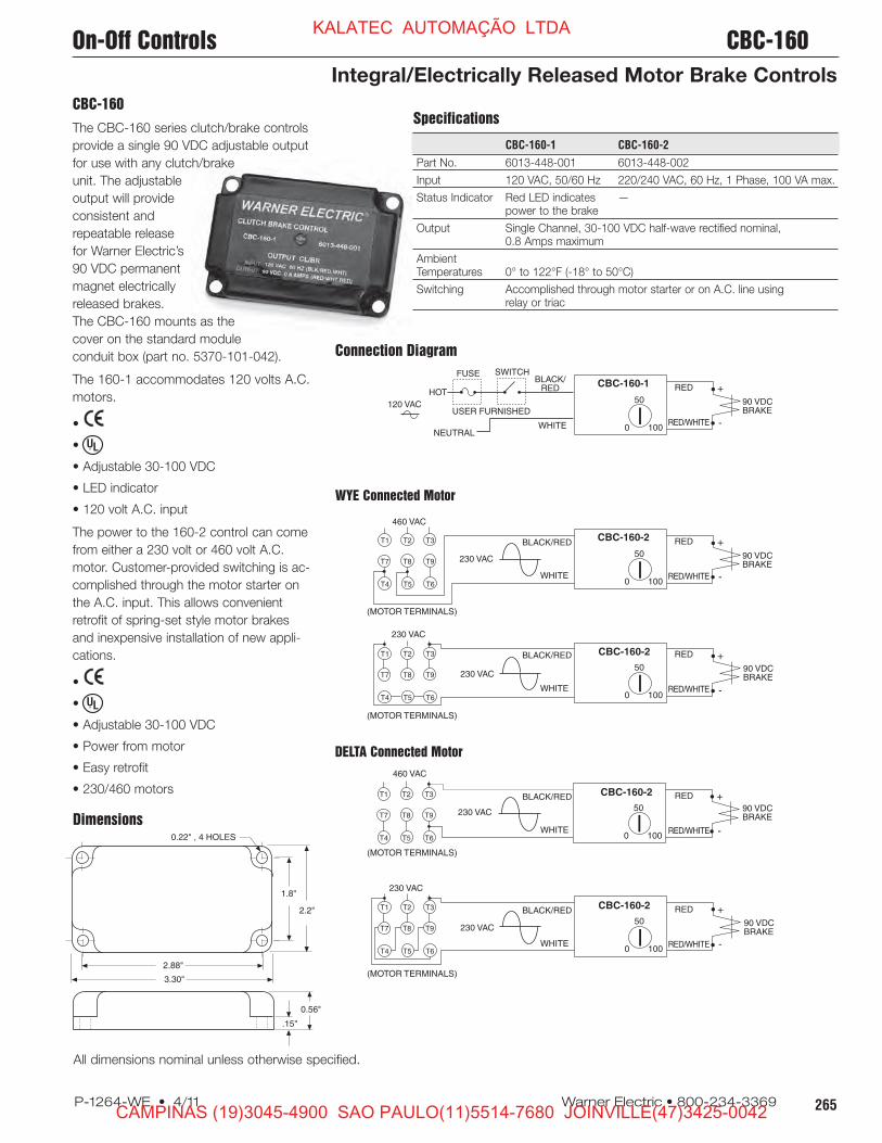
Specifications
CBC-160-1 CBC-160-2
Part No. 6013-448-001 6013-448-002
Input 120 VAC, 50/60 Hz 220/240 VAC, 60 Hz, 1 Phase, 100 VA max.
Status Indicator Red LED indicates —power to the brake
Output Single Channel, 30-100 VDC half-wave rectified nominal,0.8 Amps maximum
AmbientTemperatures 0° to 122°F (-18° to 50°C)
Switching Accomplished through motor starter or on A.C. line usingrelay or triac
CBC-160
The CBC-160 series clutch/brake controls
provide a single 90 VDC adjustable output
for use with any clutch/brake
unit. The adjustable
output will provide
consistent and
repeatable release
for Warner Electric’s
90 VDC permanent
magnet electrically
released brakes.
The CBC-160 mounts as the
cover on the standard module
conduit box (part no. 5370-101-042).
The 160-1 accommodates 120 volts A.C.
motors.
•
•
• Adjustable 30-100 VDC
• LED indicator
• 120 volt A.C. input
The power to the 160-2 control can come
from either a 230 volt or 460 volt A.C.
motor. Customer-provided switching is ac-
complished through the motor starter on
the A.C. input. This allows convenient
retrofit of spring-set style motor brakes
and inexpensive installation of new appli-
cations.
•
•
• Adjustable 30-100 VDC
• Power from motor
• Easy retrofit
• 230/460 motors
®UL
®UL
On-Off Controls CBC-160
Integral/Electrically Released Motor Brake Controls
KALATEC AUTOMAÇÃO LTDA
CAMPINAS (19)3045-4900 SAO PAULO(11)5514-7680 JOINVILLE(47)3425-0042
Page 6
266 Warner Electric • 800-234-3369 P-1264-WE • 4/11
6 5 4 3
7 8 1 2
NEUTRAL
90 V CLUTCH
OCTAL SOCKET120 VAC50/60 Hz
HOT
STOP
START
90 V BRAKE
SWITCH
USER FURNISHED
6 5 4 3
7 8 1 2
NEUTRAL
90 V CLUTCH
OCTAL SOCKET120 VAC50/60 Hz
HOT
90 V BRAKE
SWITCHUSER FURNISHED
1.718" ± .031"
1.968" ± .031" SQ.
2.437" ± .062"
STD. OCTAL KEYED PLUG
1.57"(39.9)
2.39"(60.7)
.70"(17.8)
2.40"(61)
.71"(18)
1.57"(39.9)
OCTAL SOCKET
DIN RAIL MOUNT SOCKET
The CBC-801 is a basic on-off power
supply that provides full voltage to a 90
volt clutch or brake and is activated by an
external switch. This type of power supply
is sufficient for many clutch/brake
applications.
CBC-801 series
Multi-unit capacity
The CBC-801 is a plug-in power supply
which is used with an octal socket. The
wiring connections are made at the
socket. The CBC-801 will operate two
units separately—or simultaneously. Octal
socket is purchased separately. Specifications
CBC-801-1 CBC-801-2
Part No. 6001-448-004 6001-448-006
Input Voltage 120 VAC, 50/60 Hz 220/240 VAC, 50/60 Hz
Output 90 VDC, 1.25 A max.
Circuit Protection Fused 1.6 Amp, 250 V fast-blo
AmbientTemperature -23° to 116°F (-31° to 47°C)
Max. CycleRate Limited by the clutch or brake, variable with application
Switching Single pole, double throwMinimum contact rating: 10 Amp, 28 VDC resistive or 10 Amp, 120 VACinductive
Status Indicator Red LED indicates brake is energized, Green LED indicates clutch isenergized
Mounting Two versions of octal socket are available:6001-101-001 foot mount6001-101-002 DIN rail mount
•
•
•
• For basic on-off operation
• Wiring connections made at octal
socket
• Arc suppression circuitry extends
switch life
• Fused for overload protection
• LED output indicators
• DIN rail mountable
®UL
Dimensions
Connection Diagram
All dimensions nominal unless otherwise specified.
Connection diagram
for operating clutch/brake
separately.
Connection diagramfor operating clutch/brakesimultaneously.
CBC-801 On-Off Controls
Plug-in Octal Socket Power Supplies
KALATEC AUTOMAÇÃO LTDA
CAMPINAS (19)3045-4900 SAO PAULO(11)5514-7680 JOINVILLE(47)3425-0042
Page 7
267P-1264-WE • 4/11 Warner Electric • 800-234-3369
CBC-802
PLC compatible
The CBC-802 is a power supply with
solid state circuits for load switching.
A brake and clutch may be operated
separately—or, two brakes or two
clutches, one unit on at a time. The
CBC-802 mounts on an octal socket
(purchased separately), and the wiring
connections are made at the socket
terminals. Octal socket sold separately,
refer to mounting specifications for
part number.
•
• Plug-in power supply with solid state
switching circuits—increases switch
service life
• Adjustable time delay for controlling
clutch/brake overlap
• Internally fused for overload protection
• DIN rail mountable
• LED output indicators
Specifications
CBC-802
Part No. 6002-448-001
Input 120 VAC, 50/60 Hz
Output 90 VDC, 0.5 A max.
Status Indicator Red LED indicates brake energized. Green LED indicates clutch energized.
Circuit Protection Fused 0.5 Amps, 250 V
AmbientTemperature -20° to 113°F (-29° to 45°C)
Leakage Current 500 uA max. for solid state switches
Max. Cycle Rate Limited by the clutch or brake, variable with application
Switching Momentary contact, maintained contact, or solid state open collector logicMinimum contact rating 20 VDC resistive, 0.01 AmpsMinimum input pulse—1 millisecond
Adjustments Externally adjusted potentiometer sets overlap between clutch and brakefrom 0 to 130 MS.
Mounting: Two versions of octal socket are available:6001-101-001 foot mount6001-101-002 DIN rail mount
Dimensions
Connection Diagram
3.562"
3.75"
.062"
STD. OCTAL KEYED PLUG
1.437"
1.57"(39.9)
2.39"(60.7)
.70"(17.8)
2.40"(61)
.71"(18)
1.57"(39.9)
OCTAL SOCKET
DIN RAIL MOUNT SOCKET
NEUTRAL
OCTAL SOCKET
120 VAC50/60 Hz
HOT
SWITCHUSER FURNISHED
STOP
5 3
7 8 1 2
90 V BRAKE
90 V BRAKE
46
All dimensions nominal unless otherwise specified.
On-Off Controls CBC-802
Plug-in Octal Socket Power Supplies
KALATEC AUTOMAÇÃO LTDA
CAMPINAS (19)3045-4900 SAO PAULO(11)5514-7680 JOINVILLE(47)3425-0042
Page 8
268 Warner Electric • 800-234-3369 P-1264-WE • 4/11
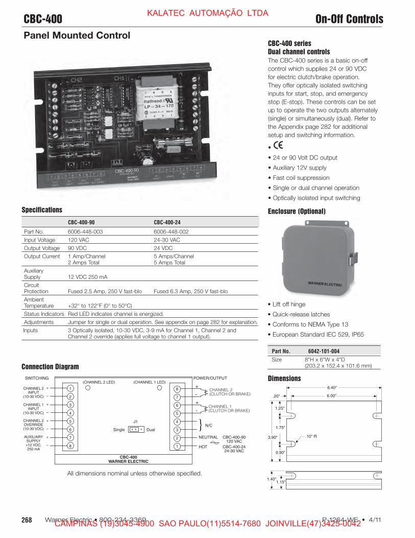
CBC-400 series
Dual channel controls
The CBC-400 series is a basic on-off
control which supplies 24 or 90 VDC
for electric clutch/brake operation.
They offer optically isolated switching
inputs for start, stop, and emergency
stop (E-stop). These controls can be set
up to operate the two outputs alternately
(single) or simultaneously (dual). Refer to
the Appendix page 282 for additional
setup and switching information.
•
• 24 or 90 Volt DC output
• Auxiliary 12V supply
• Fast coil suppression
• Single or dual channel operation
• Optically isolated input switching
Specifications
CBC-400-90 CBC-400-24
Part No. 6006-448-003 6006-448-002
Input Voltage 120 VAC 24-30 VAC
Output Voltage 90 VDC 24 VDC
Output Current 1 Amp/Channel 5 Amps/Channel2 Amps Total 5 Amps Total
AuxiliarySupply 12 VDC 250 mA
CircuitProtection Fused 2.5 Amp, 250 V fast-blo Fused 6.3 Amp, 250 V fast-blo
AmbientTemperature +32° to 122°F (0° to 50°C)
Status Indicators Red LED indicates channel is energized.
Adjustments Jumper for single or dual operation. See appendix on page 282 for explanation.
Inputs 3 Optically isolated, 10-30 VDC, 3-9 mA for Channel 1, Channel 2 andChannel 2 override (applies full voltage to channel 1 output).
Enclosure (Optional)
Dimensions
Connection Diagram
CBC-400WARNER ELECTRIC
POWER/OUTPUT
N/C• • •Single
1
2
3
4
5
6
7
8
NEUTRAL CBC-400-90120 VAC
HOT CBC-400-2424-30 VAC
8
7
6
5
4
3
2
1
Dual
(CHANNEL 2 LED) (CHANNEL 1 LED)
CHANNEL 2(CLUTCH OR BRAKE)
CHANNEL 1(CLUTCH OR BRAKE)
J1
+
-
+
-
CHANNEL 1INPUT
(10-30 VDC)
CHANNEL 2INPUT
(10-30 VDC)
AUXILIARYSUPPLY+12 VDC,250 mA
CHANNEL 2OVERRIDE(10-30 VDC)
+
–
+
–
+
–
+
–
SWITCHING
1.75"
0.90"
6.00".20"
3.90"
1.15"
1.25"
1.40"
6.40"
.10" R
All dimensions nominal unless otherwise specified.
• Lift off hinge
• Quick-release latches
• Conforms to NEMA Type 13
• European Standard IEC 529, IP65
Part No. 6042-101-004
Size 8"H x 6"W x 4"D(203.2 x 152.4 x 101.6 mm)
CBC-400 On-Off Controls
Panel Mounted Control
KALATEC AUTOMAÇÃO LTDA
CAMPINAS (19)3045-4900 SAO PAULO(11)5514-7680 JOINVILLE(47)3425-0042
Page 9
269P-1264-WE • 4/11 Warner Electric • 800-234-3369
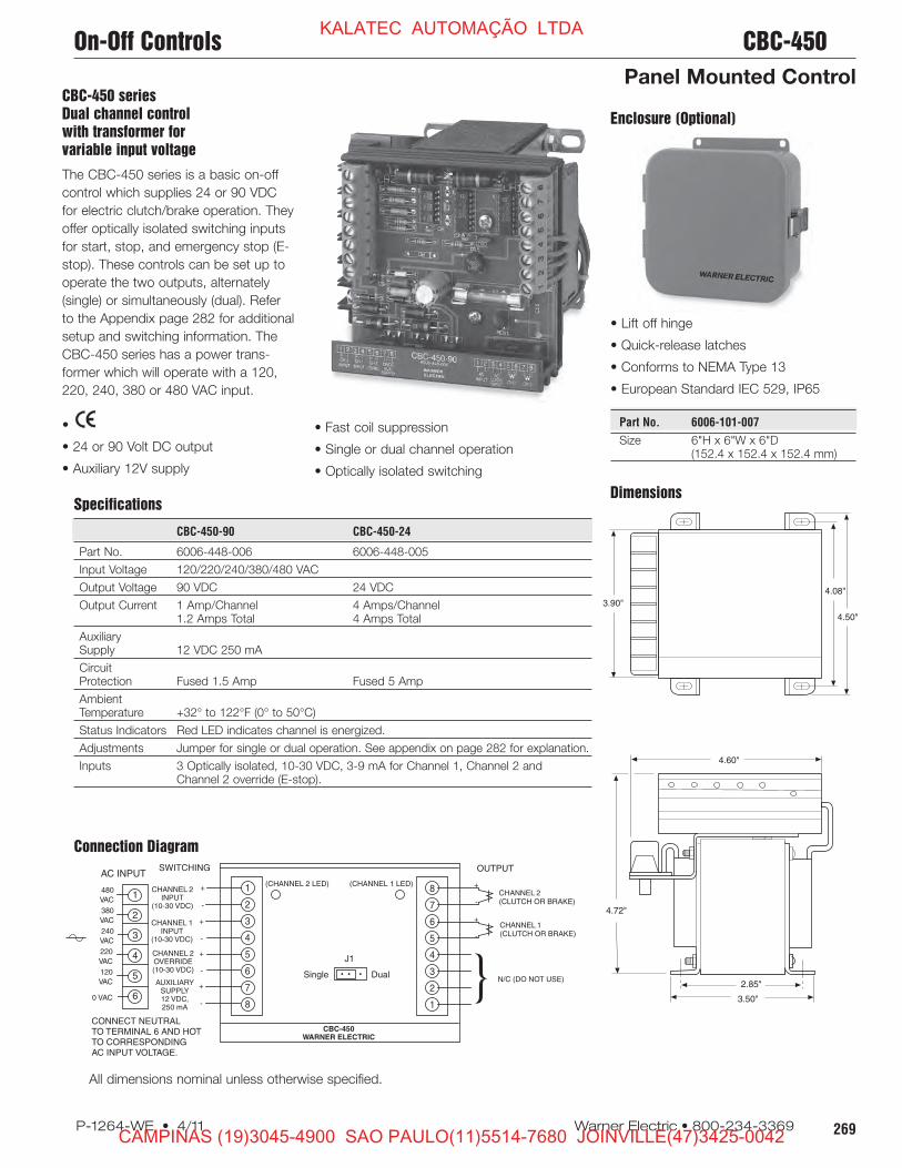
Specifications
CBC-450-90 CBC-450-24
Part No. 6006-448-006 6006-448-005
Input Voltage 120/220/240/380/480 VAC
Output Voltage 90 VDC 24 VDC
Output Current 1 Amp/Channel 4 Amps/Channel1.2 Amps Total 4 Amps Total
AuxiliarySupply 12 VDC 250 mA
CircuitProtection Fused 1.5 Amp Fused 5 Amp
AmbientTemperature +32° to 122°F (0° to 50°C)
Status Indicators Red LED indicates channel is energized.
Adjustments Jumper for single or dual operation. See appendix on page 282 for explanation.
Inputs 3 Optically isolated, 10-30 VDC, 3-9 mA for Channel 1, Channel 2 andChannel 2 override (E-stop).
Dimensions
Connection Diagram
CBC-450WARNER ELECTRIC
AC INPUT
CHANNEL 1INPUT
(10-30 VDC)
CHANNEL 2INPUT
(10-30 VDC)
AUXILIARYSUPPLY12 VDC,250 mA
CHANNEL 2OVERRIDE(10-30 VDC)
1
2
3
4
5
6
480
VAC
380
VAC
240
VAC
220
VAC
120
VAC
0 VAC
+
-
+
-
+
-
+
-
1
2
3
4
5
6
7
8
+
-
+
-
8
7
6
5
4
3
2
1
OUTPUTSWITCHING
CONNECT NEUTRALTO TERMINAL 6 AND HOTTO CORRESPONDINGAC INPUT VOLTAGE.
CHANNEL 2(CLUTCH OR BRAKE)
CHANNEL 1(CLUTCH OR BRAKE)
N/C (DO NOT USE)
(CHANNEL 2 LED) (CHANNEL 1 LED)
• • •Single Dual
J1
Enclosure (Optional)
4.60"
2.85"
3.50"
4.72"
4.50"
4.08"
3.90"
CBC-450 series
Dual channel control
with transformer for
variable input voltage
The CBC-450 series is a basic on-off
control which supplies 24 or 90 VDC
for electric clutch/brake operation. They
offer optically isolated switching inputs
for start, stop, and emergency stop (E-
stop). These controls can be set up to
operate the two outputs, alternately
(single) or simultaneously (dual). Refer
to the Appendix page 282 for additional
setup and switching information. The
CBC-450 series has a power trans-
former which will operate with a 120,
220, 240, 380 or 480 VAC input.
•
• 24 or 90 Volt DC output
• Auxiliary 12V supply
• Fast coil suppression
• Single or dual channel operation
• Optically isolated switching
• Lift off hinge
• Quick-release latches
• Conforms to NEMA Type 13
• European Standard IEC 529, IP65
Part No. 6006-101-007
Size 6"H x 6"W x 6"D(152.4 x 152.4 x 152.4 mm)
All dimensions nominal unless otherwise specified.
On-Off Controls CBC-450
Panel Mounted Control
KALATEC AUTOMAÇÃO LTDA
CAMPINAS (19)3045-4900 SAO PAULO(11)5514-7680 JOINVILLE(47)3425-0042
Page 10
270 Warner Electric • 800-234-3369 P-1264-WE • 4/11
2.75"
4.38"
.56" 5.50"
6.63"
2.75"
.19" DIA.MTG. HOLES (4)
.50"
1.00"
.50" CONDUIT SIZEBOTH SIDES
3.00"
.69"
1
2
3
4
5
6
7
+
-K1K2
120 VAC
50/60 Hz
+90V
ADJ. OUTPUT
RHEOSTAT1000Ω50W
6010-101-002(not included)
120 VAC
50/60 Hz
1
2
3
4
5
6
7
+90V
+ADJ.VOLTAGE
TORQUE CONTROL
SWITCH
(USER FURNISHED)
(NEUT)
(HOT)
STOP
START
90 VOLT UNIT
90 VOLT UNIT
+ CLUTCH
+ BRAKE
1
2
3
4
5
6
7
+90V
ADJ.VOLTAGE
CLUTCH
ELECTRICALLY
RELEASED BRAKE
SWITCH
120 VAC50/60 Hz
(USER FURNISHED)
(NEUT)
(HOT)
Energize K1,
Brake released
Energize K1 & K2,
Softstop Brake
Full Brake On as shown
ELECTRICALLY
RELEASED
BRAKE
Specifications
MCS-103-1
Part No. 6010-448-002
Input 120 VAC, 50/60 Hz
Output 1.25 Amp90 V full wave rectified for one unit and adjustable from0-90 volts full wave rectified for second unit
Circuit Protection Fused 1.5 Amp, 250 V
AmbientTemperature -20° to 113°F (-29° to 45°C)
Maximum Cycle Rate Limited by the clutch or brake and will vary with application.
Mounting Mounting centers 5-1/2" wide, 3" high. Knockouts for 1/2" conduit
External Switches Double pole, double throw maintained contact. Minimum contact(User furnished) rating: 10 Amp, 28 VDC resistive or 10 Amp, 120 VAC inductive.
Contact ratings given will operate all Warner Electric brake and clutchunits. However, switches with ratings less than those given may beused with fractional horsepower units provided the rating is equal to orgreater than the coil current.
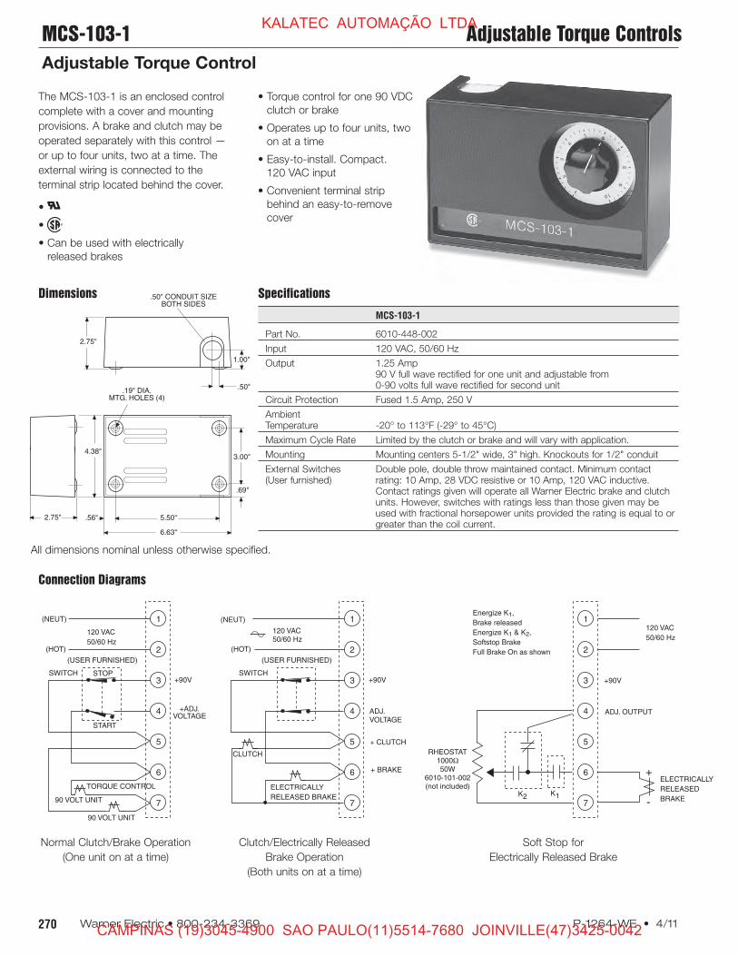
The MCS-103-1 is an enclosed control
complete with a cover and mounting
provisions. A brake and clutch may be
operated separately with this control —
or up to four units, two at a time. The
external wiring is connected to the
terminal strip located behind the cover.
•
•
• Can be used with electrically
released brakes
Dimensions
Connection Diagrams
All dimensions nominal unless otherwise specified.
Soft Stop for
Electrically Released Brake
Normal Clutch/Brake Operation
(One unit on at a time)
Clutch/Electrically Released
Brake Operation
(Both units on at a time)
• Torque control for one 90 VDC
clutch or brake
• Operates up to four units, two
on at a time
• Easy-to-install. Compact.
120 VAC input
• Convenient terminal strip
behind an easy-to-remove
cover
MCS-103-1 Adjustable Torque Controls
Adjustable Torque Control
KALATEC AUTOMAÇÃO LTDA
CAMPINAS (19)3045-4900 SAO PAULO(11)5514-7680 JOINVILLE(47)3425-0042
Page 11
271P-1264-WE • 4/11 Warner Electric • 800-234-3369
Power Supply MCS-805-1, MCS-805-2
Connection Diagram
Connect the MCS-805-1 or MCS-805-2 Power Supply per the following diagram and instructions:
The DC voltage required to release the Warner Electric ER-1225 Brake is supplied by
the MCS-805-1 or MCS-805-2 Power Supply. The correct brake release voltage—
approximately 35-75 volts DC—is set by adjusting the power supply at the time of
brake installation. Temperature compensating circuits provide proper operation over
the entire operating range of 0°F to 150°F. Switching may be provided on either the
AC or DC side of the power supply. The MCS-805-1 may be mounted on its back
panel or on 1/2" conduit. The MCS-805-2 has a torque adjustment capability for soft
stop applications. The MCS-805-2 requires two switching circuits when used for those
applications requiring soft engagement.
MCS 805-1
1 2 3 4
1 2 3 4 5 6 7 8 9
1 2 3 4
120 VAC
MCS 805-2
1 2 3 4
1 2 3 4 5 6 7 8 9
1 2 3 4
120 VAC
AC INPUT*120/230 VAC*50/60 Hz
230 VAC 230 VAC
– +
BrakeDC Switching
(Jumper if not used)
S1
S1 S1
S2
GND AC INPUT*120/230 VAC*50/60 Hz
– +
BrakeDC Switching*
Closed – brake release*Open – brake in tq. adj. mode
S1
GND
S1Open – brake engaged*Closed – brake released
or tq. adj. mode per S1
0.28 Diameter (4) Mtg Holes*Clearance for .25" Screw
BACK
0.875 Diameter *Knockouts for 0.50 *Conduit Both EndsTypical
TOP AND BOTTOM
3.44
2.625
1.125
FRONT
7.125
5.0
SIDE
3.44
0.56
6.0
4.81
5.0
3.750.53
Dimensions
Specifications
MCS-805-1 MCS-805-2
Part No. 6090-448-006 6090-448-007
Input 115/230 VAC, 50/60 Hz ±10% 115/230 VAC, 50/60 Hz ±10%
Output 0.4 Amp, 35/75 VDC 0.4 Amp, 35/75 VDC
AmbientTemperature -20° to 150°F (-29° to 65°C) -20° to 150°F (-29° to 65°C)
Maximum Limited by the clutch or brake and will vary with application.Cycle Rate Consult factoryfor specifics.
External Switches For DC switching: single pole, single throw.(User furnished) Minimum contact rating 1 amp, 120 volts DC resistive.
For AC switching: single pole, single throw.Minimum contact rating 1 amp, 120 volts AC.
Circuit Protection .75 Amp 250V Slow Blow 3 AG
For AC switching, switch may be in series with input supply.
For DC switching, use terminals 7 and 8 as shown.
KALATEC AUTOMAÇÃO LTDA
CAMPINAS (19)3045-4900 SAO PAULO(11)5514-7680 JOINVILLE(47)3425-0042
Page 12
272 Warner Electric • 800-234-3369 P-1264-WE • 4/11
1 2 3 4 5 6 7 8 9TB1
120VAC
50/60 Hz
G
H
NOR
G
H
N
CBC-300 ISADJUSTABLE BOTH
CHANNELS.
CBC-200 IS FIXEDVOLTAGE CHANNEL 2
1-1/2 A
CH-1 CH-2
+ - + -
SW1 SW2 ADJUSTABLEVOLTAGE CHANNEL 1
.750"± .020"(19.1± .508)
1.345"± .020"(34.2± .508)
1.750"± .010"(44.5± .254)
2.063"(52.4)NOM.
6.500"(165.1)NOM.
1.183"(46.1)NOM.
2.500"(63.5)NOM. 1.095"
(27.8)REF.
2.250" ± .010"(57.2 ± .254)
5.187" ±
.020"
(131.7 ± .508)
4.460"(113.3)NOM.
.180"(.46) DIA.
MTG. HOLE
.620"(15.7)REF.
Specifications
CBC-200 CBC-300
Part No. 6011-448-001 6021-448-001
Input Power 120 VAC +10% -15%, 50/60 Hz, single phase, 215 VA max.
Output Pulse-width modulated full wave rectified D.C. Constant current,switch selectable ranges, 0-90 volt
Ambient +32°F to +113°F (0°C to 45°C) with plastic cover installedTemperature +32°F to +150°F (0°C to 66°C) with plastic cover removed
Circuit Internal line to line short circuit protectionProtection Optional customer supplied fusing on A.C. line, 1.5 Amps, 250 VAC.
Fast-acting fuse recommended
Current Adjust(via front panel Single adjustable channel Dual adjustable channelspotentiometers)
Status “POWER”—green LED indicates A.C. power is applied to theindicators control. “SHORT”—red LED indicates a short circuit condition exists on one
or both outputs.
Internal Set DIP switches SW1 and SW2 to suit the current draw of the connectedAdjustments connected clutch/brake coil:
Switch Range 1 2 3 4 5Max CurrentDraw (mA) 60 175 245 305 533
External Mechanical or electromechanical—customer supplied:Switching 1 Amp, 125 V minimum rating
Solid-state, NPN isolated transistor—customer supplied:2 Amp, J250 V minimum rating. Maximum off state leakage current <1 mA
Dimensions
Connection Diagram
The CBC-200 and CBC-300 Controls
provide single/dual torque control when
connected to any of Warner Electric’s
90 volt clutches and brakes.
Common features
• and
• Current monitored output maintains
consistent torque regardless of
variation in coil temperature.
• Switch selection tunes control to
exactly match power requirements
and operating characteristics of each
clutch or brake.
• Individual torque adjust allows preset
maximum torque tailored to applica-
tion requirements.
• Short circuit protection, line to line.
• Torque limiting protects machine
components from damage.
• Can be used with electrically released
brakes.
®UL
CBC-200
Dual channel/Single channel torque
adjust
The CBC-200 is a dual channel control
with one adjustable current and one
fixed voltage.
CBC-300
Dual channel/Dual channel torque
adjust
The CBC-300 has two adjustable
current channels.
CBC-200, CBC-300 Adjustable Torque Controls
Single or Dual Channel Adjustable Torque Control
KALATEC AUTOMAÇÃO LTDA
CAMPINAS (19)3045-4900 SAO PAULO(11)5514-7680 JOINVILLE(47)3425-0042
Page 13
273P-1264-WE • 4/11 Warner Electric • 800-234-3369
CHANNEL 2 OVERRIDE INPUT(10-30 VDC)
CBC-500WARNER ELECTRIC
POWER/OUTPUT
CHANNEL 1 INPUT(10-30 VDC)
CHANNEL 2 INPUT(10-30 VDC)
AUXILIARYSUPPLY
12 VDC, 250 mA
SWITCHING
+
-
+
-
+
-
+
-
1
2
3
4
5
6
7
8
CHANNEL 2(CLUTCH ORBRAKE)
8
7
6
5
4
3
2
1
CHANNEL 1(CLUTCH ORBRAKE)
+
-
+
-
N/C (DO NOT USE)
CBC-500-90120 VAC
CBC-500-2424-30 VAC
Dual
Single
(CHANNEL 2 LED) (CHANNEL 1 LED)
J2
J1
(CHANNEL 1ADJUST)
(CHANNEL 2ADJUST)
FREQUENCYADJUST
• • • •
• • • •1.75"
0.90"
6.00"0.20"
3.90"
1.15"1.40"
6.40"
CBC-500 series
Dual torque adjustable
power supplies
The CBC-500 series is a dual channel ad-
justable voltage control with optically
isolated input switching for 24 and 90 volt
electric clutches and brakes. These controls
can be set up to energize the two outputs
alternately (single) or simultaneously (dual).
Refer to the Appendix page 282 for
additional setup and switching information.
•
• Dual adjustable channels
• Optically isolated input switching
• Single or dual channel operation
• Auxiliary 12V supply
• Can be used with electrically
released brakes
• Lift off hinge
• Quick-release latches
• Conforms to NEMA Type 13
• European Standard IEC 529, IP65
Part No. 6042-101-004
Size 8"H x 6"W x 4"D(203.2 x 152.4 x 101.6 mm)
Connection Diagram
Dimensions
Enclosure (Optional)
All dimensions nominal unless otherwise specified.
Specifications
CBC-500-90 CBC-500-24
Part No. 6024-448-003 6024-448-002
Input Voltage 120 VAC 24-30 VAC
Output Voltage 0-90 VDC 0-24 VDC
Output Current 1 Amp/Channel 5 Amps/Channel2 Amps Total 5 Amps Total
AuxiliarySupply 12 VDC 250 mA 12 VDC 250 mA
Circuit Fused FusedProtection 2.5 Amp, 250 V Fast-blo 6.3 Amp, 250 V Fast-blo
AmbientTemperature +32° to 122°F (0° to 50°C)
StatusIndicators Red LED indicates channel is energized.
Adjustments Two potentiometers for voltage adjustment of channel 1 and channel 2 outputfrom 0 to full rated voltage. Frequency adjustment from 60 to 400 Hz to reduceclutch/brake “Hum” associated with machine frequencies. Jumper for single ordual operation. See appendix on page 282 for explanation.
Inputs: 3 Optically coupled, 10-30 VDC, 3-9 mA for Channel 1, Channel 2 andChannel 2 override (applies full voltage to channel 1 output)
Adjustable Torque Controls CBC-500
Panel Mounted
KALATEC AUTOMAÇÃO LTDA
CAMPINAS (19)3045-4900 SAO PAULO(11)5514-7680 JOINVILLE(47)3425-0042
Page 14
274 Warner Electric • 800-234-3369 P-1264-WE • 4/11
Specifications
CBC-550-90 CBC-550-24
Part No. 6024-448-006 6024-448-005
Input Voltage 120/220/240/380/480 VAC
Output Voltage 0-90 VDC 0-24 VDC
Output Current 1 Amp/Channel 4 Amps/Channel1.2 Amps Total 4 Amps Total
AuxiliarySupply 12 VDC 250 mA 12 VDC 250 mA
Circuit Fused FusedProtection 1.5 Amp, 250 V fast-blo 5 Amp, 250 V fast-blo
AmbientTemperature +32° to 122°F (0° to 50°C)
StatusIndicators Red LED indicates channel is energized.
Adjustments Two potentiometers for voltage adjustment of channel 1 and channel 2 outputfrom 0 to full rated voltage. Frequency adjustment from 60 to 400 Hz to reduceclutch/brake “Hum” associated with machine frequencies. Jumper for single ordual operation. See appendix on page 282 for explanation.
Inputs 3 Optically coupled, 10-30 VDC, 3-9 mA for Channel 1, Channel 2 andChannel 2 override (applies full voltage to channel 1 output)
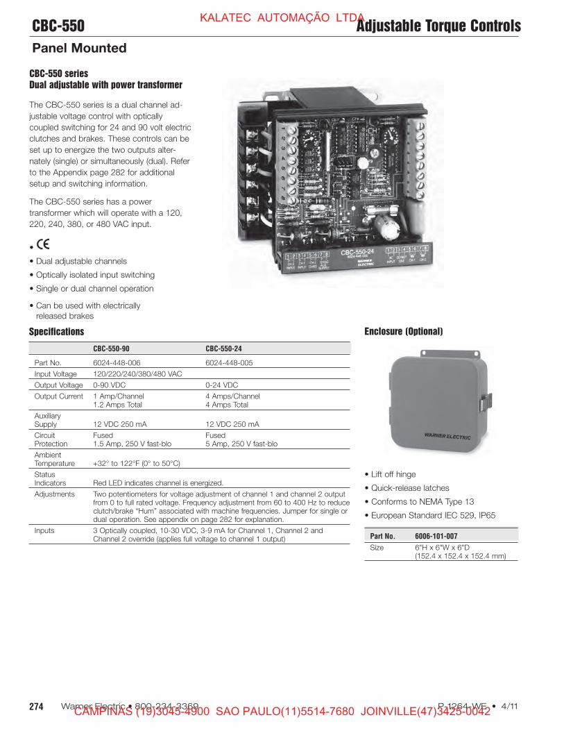
Enclosure (Optional)
• Lift off hinge
• Quick-release latches
• Conforms to NEMA Type 13
• European Standard IEC 529, IP65
Part No. 6006-101-007
Size 6"H x 6"W x 6"D(152.4 x 152.4 x 152.4 mm)
CBC-550 series
Dual adjustable with power transformer
The CBC-550 series is a dual channel ad-
justable voltage control with optically
coupled switching for 24 and 90 volt electric
clutches and brakes. These controls can be
set up to energize the two outputs alter-
nately (single) or simultaneously (dual). Refer
to the Appendix page 282 for additional
setup and switching information.
The CBC-550 series has a power
transformer which will operate with a 120,
220, 240, 380, or 480 VAC input.
•
• Dual adjustable channels
• Optically isolated input switching
• Single or dual channel operation
• Can be used with electrically
released brakes
CBC-550 Adjustable Torque Controls
Panel Mounted
KALATEC AUTOMAÇÃO LTDA
CAMPINAS (19)3045-4900 SAO PAULO(11)5514-7680 JOINVILLE(47)3425-0042
Page 15
275P-1264-WE • 4/11 Warner Electric • 800-234-3369
CBC-550
WARNER ELECTRIC
AC INPUT
CHANNEL 1
INPUT
(10-30 VDC)
CHANNEL 2
INPUT
(10-30 VDC)
AUXILIARY
SUPPLY
12 VDC,
250 mA
CHANNEL 2
OVERRIDE
(10-30 VDC)
1
2
3
4
5
6
480
VAC
380
VAC
240
VAC
220
VAC
120
VAC
0 VAC
+
-
+
-
+
-
+
-
1
2
3
4
5
6
7
8
+
-
+
-
8
7
6
5
4
3
2
1
OUTPUTSWITCHING
CONNECT NEUTRAL
TO TERMINAL 6 AND HOT
TO CORRESPONDING
AC INPUT VOLTAGE.
CHANNEL 2
(CLUTCH OR BRAKE)
CHANNEL 1
(CLUTCH OR BRAKE)
N/C (DO NOT USE)
Dual
Single
(CHANNEL 2 LED) (CHANNEL 1 LED)
J2
J1
(CHANNEL 1ADJUST)
(CHANNEL 2ADJUST)
FREQUENCYADJUST
• • • •
• • • •
4.60"
2.85"
3.50"
4.72"4.50"
4.08"3.90"
Dimensions
Connection Diagram
All dimensions nominal unless otherwise specified.
Adjustable Torque Controls CBC-550
Panel Mounted
KALATEC AUTOMAÇÃO LTDA
CAMPINAS (19)3045-4900 SAO PAULO(11)5514-7680 JOINVILLE(47)3425-0042
Page 16
276 Warner Electric • 800-234-3369 P-1264-WE • 4/11
CLUTCHSWITCH
+12 VDC
HOLD LEVEL SET-UP SWITCH*(Up: Normal, Down: Set-Up)
CLUTCH LED*
BRAKE LED*
SHORT CIRCUIT LED
*OPEN:CLUTCH*
CLOSEDBRAKE
BRAKE*
CLUTCH
120 VAC
SELECT**
OUTPUT*INHIBIT*
*COMMON
4
3
2
17
6
5
4
3
2
1
CLUTCH*INITIAL*PULSE*
CLUTCH*RAMPTIME
CLUTCH*HOLDLEVEL*
CLUTCH*TORQUE*ADJUST*
BRAKE*RAMPTIME*
BRAKE*HOLDLEVEL*
BRAKE*TORQUE*ADJUST*
BRAKE*INITIAL*PULSE
FUSE
FRONT VIEW
BACK VIEWTOP VIEW
4.25"(108)
5.00"(127)
6.50"(165)
5.00"(127)
5.00"(127)
0.31" TYP.*(7.9)
0.15"R TYP.*(3.8)
0.25"(6.4)
4.50"(114)
0.75"(19)
Initial Pulse*
Adjustment
Ramp Time*
Adjustment
Hold Level*
Adjustment
Torque*
Adjustment
Time
Current
Specifications
CBC-1825R
Part No. 1825-448-001
Input Voltage 120 VAC, 50/60 Hz, 100 VA maximum
Output Current Current driven PWM, compatible with 90 VDC clutch/brake(switch selectable current output)
Auxiliary Supply 12 VDC 250 mA
Circuit Protection Input Fused 1.5 Amp, 250 V fast-bloclutch and brake outputs are short circuit protected
Status Indicators Clutch and brake LEDs indicate output is energizedShort circuit LED indicates a fault
Ambient Temperature 0° to 122°F (-18° to 50°C)
Switching Contact rating: 15 mA @ 15 V, open collector NPN 2mA maximumallowable leakage current and 2 V maximum saturation voltage
Set-up
Connection Diagram
Dimensions
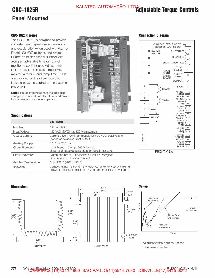
CBC-1825R series
The CBC-1825R is designed to provide
consistent and repeatable acceleration
and deceleration when used with Warner
Electric 90 VDC clutches and brakes.
Current to each channel is introduced
along an adjustable time ramp and
monitored continuously. Adjustments
include initial pull-in pulse, hold level,
maximum torque, and ramp time. LEDs
are provided on the circuit board to
indicate power is applied to the clutch or
brake unit.
Note: It is recommended that the auto-gapsprings be removed from the clutch and brakefor successful accel-decel application.
All dimensions nominal unless
otherwise specified.
CBC-1825R Adjustable Torque Controls
Panel Mounted
KALATEC AUTOMAÇÃO LTDA
CAMPINAS (19)3045-4900 SAO PAULO(11)5514-7680 JOINVILLE(47)3425-0042
Page 17
277P-1264-WE • 4/11 Warner Electric • 800-234-3369
1
2
3
4
5
6
7
8
9
10
11
120 VAC50/60 Hz
SW
BK
CL
CR
CR, SW user furnished switchoptions for use with control.
normally open relay contact normally open push button switch
NOTE:
CRSW
TYPICAL 3 WIRESWITCHING
CONFIGURATION
HOT
NEUTRAL
+
–
+
–
+
–
AUXILIARYSUPPLY(+12V)
BRAKE INPUT(10-30VDC)
CLUTCH INPUT(10-30VDC)
5.00" (12.70)
3.25"
(82.5)4.65"
(118.1)
.95" (24.1)
.50" (12.7)
.125" (3.2)RTYP.
.50" (12.7)
Specifications
CBC-700-90 CBC-700-24
Part No. 6042-448-003 6042-448-002
Input 120 VAC, 50/60 Hz 24-28 VAC, 50/60 Hz
Output VoltagesSteady State 90 VDC 24 VDCOverexcitation 340 VDC 105 VDC
Output Current(Per channel .5 Amps 3.5 Ampsalternately)
OEX Pulse Adjustable through logic board dip switchesDuration (see service manual)
Inputs Two-optically isolated (10-30 VDC)
AmbientTemperature 0°F to 140°F (-18°C to +60°C)Range
Maximum OffState Leakage <2 mA (inputs)
CircuitProtection 2.5A Slo-Blo (5 x 20 mm) 5A Slo-Blo (5 x 20 mm)
Auxiliary Supply 12 VDC, 250 mA maximum
Enclosure (Optional)
DimensionsConnection Diagram
• Lift off hinge
• Quick-release latches
• Conforms to NEMA Type 13
• European Standard IEC 529, IP65
Part No. 6042-101-004
Size 8"H x 6"W x 4"D(203.2 x 152.4 x 101.6 mm)
CBC-700 series
Simple, compact, high performance OEX
control for either 90 or 24 VDC clutches
and brakes. OEX spike duration and
anti-overlap times delay are adjustable.
Two optically isolated inputs.
•
• High performance
• Switch selectable OEX duration
• Force decay suppression with
adjustable anti-overlap time delay
• Compact, flexible mounting
• Models for 24 or 90 volt clutches
and brakes
• Cycle rate limited by clutch/brake
All dimensions nominal
unless otherwise specified.
Overexcitation Controls CBC-700
General Purpose OEX Control
KALATEC AUTOMAÇÃO LTDA
CAMPINAS (19)3045-4900 SAO PAULO(11)5514-7680 JOINVILLE(47)3425-0042
Page 18
278 Warner Electric • 800-234-3369 P-1264-WE • 4/11
Specifications
CBC-750-6 CBC-750-24 CBC-750-90
Part No. 6041-448-001 6041-448-002 6041-448-003
Input Power 120/220/240 VAC, ±10%, 50/60 Hz, 350 VA (switch selectable)
Control Inputs Opto-isolated 10-30 VDC @ 10-35 mA nominal sinking or sourcing, or 24 VAC (50/60Hz) @ 22 mA nominal, or 120 VAC (50/60 Hz) @ 20 mA nominal
Clutch/brake OutputSteady State OutputCurrent controlled .910 to 4.34 A max. .227 to 1.175 A max. .060-.310 A max.Current Rise Time Dependent on clutch/brake sizeCurrent Fall Time Depending on clutch/brake sizeOverexcitation Voltage 75 VDC nom. 240 VDC nom. 450 VDC nom.Overexcitation Time Automatic adjustment by control feedbackAnti-overlap Time Automatic adjustment by control feedback
Power Supply Output 12 VDC, ±0.6 VDC, 250 mA max.
Auxiliary Indicator Opto-isolated NPN transistorsOutputs 24 VDC maximum, 20 mA max., reverse polarity protected
Circuit Protection Internal short circuit protection on each output channel.
FusingAC Input Line 2 Amp, 250 V Slo-BloOEX Supply 10 Amp, 32 V Slo-Blo 5 Amp, 250 V Slo-Blo 1 Amp, 250 V Slo-Blo
•
• High performance OEX control
• Constant current output capability
• Models for 6, 24, and 90 V clutches
and brakes
• Outputs short circuit protected.
• AC/DC optically isolated inputs
• Transformer isolation
Remote torque potentiometer
capability
• Input/Output inhibit functions
• Switch selectable OEX function
• Automatic CH1/CH2 anit-overlap
feature
• Heavy duty suppression circuits
• Selectable output current ranges
• Remote status indicators inputs
and outputs
CBC-750 series
Dual channel, current based OEX with
switch ing logic
Warner Electric’s CBC-750 series of
Constant Current Overexcitation
Clutch/Brake Controls are solid-state
electronic controls designed to increase
the cycle rate capabilities and accuracies
of electromagnetic clutches and brakes.
The controls accomplish this by sending
a momentary high voltage overexcitation
spike to the clutch and/or brake magnetic
coil to build a high density magnetic flux
field almost instantaneously. By using
overexcitation, the response time is
reduced as dramatically as performance
is increased. For example, the current
build up time of a 5 inch, 6 volt magnet is
reduced from 84 milliseconds to 2
milliseconds.
The CBC-750 user selects either 120,
220 or 240 VAC operation at the time of
installation. Models for 6 volt, 24 volt, or
90 volt clutches and brakes are available.
LED indicators on the faceplate of each
control tell the user the status of input
signals, output activation and any auxiliary
inputs. A reset switch resets the output
should a short be detected. Remote
torque adjust potentiometer inputs are
also provided. Appropriate current range
for each size clutch or brake is selected
by a dip switch. Constant current for
each level is assured by the control’s
design.
• Maintains torque at preset levels
regardless of temperature variations
• Automatically controls OEX pulse
duration for optimum response without
overheating coils
• Automatically prevents clutch and brake
“overlap”
• Configurable as an analog follower
control through remote top input
Shown with optional
cover, part number
6041-101-004
CBC-750 Overexcitation Controls
Rapid Acceleration/Deceleration
KALATEC AUTOMAÇÃO LTDA
CAMPINAS (19)3045-4900 SAO PAULO(11)5514-7680 JOINVILLE(47)3425-0042
Page 19
279P-1264-WE • 4/11 Warner Electric • 800-234-3369
1
2
3
4
5
6
7
120/220/240 VAC
50/60 Hz
CHANNEL 1
(CLUTCH OR BRAKE)
CHANNEL 2
(CLUTCH OR BRAKE)
CR
Minimum Connection Diagram using DC inputs.
1
2
3
4
5
6
7
TB1COMMONCONNECTIONS
TB2
10-30 VDC CONNECTION
1
2
3
4
5
6
7
8
TB5Q
1
2
3
4
5
6
7
TB6
Q, CR user furnished switchoptions for use with control.
NPN transistor normally open relay contact
NOTE:
QCR
AUXILIARYSUPPLY12 VDC
CHANNEL1OPTIONALREMOTETORQUEPOTENTIOMETER
CHANNEL 2OPTIONALREMOTETORQUEPOTENTIOMETER
+
-
SW8
SW6
SW10
SW3 SW11
SW5
SW2
SW4
SW7
SW5*
Channel 1 OEX*
enable ( ) / disable ( )*
*
SW2*
Channel 1 local ( )*
or remote ( )*
torque adjust*
*
SW4*
Channel 2 local ( )*
or remote ( )*
torque adjust*
*
SW11*
Auxiliary input selector*
Channel 1 ( )*
Channel 2 ( )
SW6*
Channel 2 OEX*
enable ( )*
disable ( )*
*
SW10*
Channel 1 *
input invert*
( ) ( )*
*
SW3*
Level/pulse *
selector *
level ( )*
pulse ( )
SW8*
Channel 2 current range selector*
(settings in diagram below)
SW7*
Channel 1 current range selector*
(settings in diagram below)
All switches are in the down ( ) position from factory
Channel 1*
Torque Adjust*
(0-Full Voltage)
Channel 2*
Torque Adjust*
(0-Full Voltage)
5.69" (144.53)
14.01" (355.85)
13.00" (330.20)
11.50" (292.10)
7.50"(190.50)
9.56"(242.82)
9.77"(244.16)
4.78"(121.41)
10.75"(273.05)
3.09"(78.49)
1.12" (28.45) DIA.
1.25" (31.75)
2.69"(68.33)
.88" (22.35) DIA.CONDUIT ENTRANCE (3)
3.16"(80.26)
3.00"(76.20)
.218" (5.54) DIA.MTG. HOLES (4)
Dimensions
Connection Diagram
Setup Switches
SW1: AC Voltage selection switch on
terminal board inside control unit
Max. Current Output
(SW7 & SW8 settings)
Nominal
Voltage 1 2 3 4 5
6 0.910 2.35 3.183 3.760 4.340
24 0.227 0.641 0.881 0.940 1.175
90 0.060 0.176 0.256 0.282 0.310
Seven optically isolated inputs accept 10-
30V A.C./D.C. (TB2) or 120 VAC (TB3),
configured through set-up switches
1. Channel 2 Input
2. Channel 2 Input Inhibit
(disregards channel 2 input signal)
3. Auxiliary Input
4. Channel 1 Input
5. Channel 1 Input Inhibit
(disregards channel 1 input signal)
6. Output Inhibit
(deactivates both output channels)
7. Channel 2 Override
(applies full voltage to channel 1
output)
Overexcitation Controls CBC-750
Rapid Acceleration/Deceleration
KALATEC AUTOMAÇÃO LTDA
CAMPINAS (19)3045-4900 SAO PAULO(11)5514-7680 JOINVILLE(47)3425-0042
Page 20
280 Warner Electric • 800-234-3369 P-1264-WE • 4/11
CBC-1000
Position-loop control with error
correction compensationWarner Electric’s CBC-1000 is a closed-loop positioning control with errorcompensation designed for industrialclutch/brake applications. The positionloop is closed through encoder feedbackwhich generates pulses proportional toload motion. The CBC-1000 uses thisfeedback to determine the optimumbrake actuation point. The control can beprogrammed to operate in one of twodistinct modes: absolute or incremental.The CBC-1000 includes eight solid statecontrol outputs, a batch counter and aserial com mu ni ca tions interface.
The CBC-1000 system consists of fourkey elements: the CBC-1000, aclutch/brake, a clutch/brake control, andan encoder. Nearly any electricclutch/brake size and con fig u ra tion canbe used. The clutch/brake control shouldhave solid-state compatibility. Simple on-off, soft start/stop, and overexcitationcontrols may all be utilized based on thedesired velocity profile.
Specifications
Part No. 6060-448-001
Input Power 100 to 130 VAC, 50/60 Hz, 20VA (200 to 260 VAC selectable)
Auxiliary Supply 12 VDC @ 175 mA Used for powering encoder, etc.
Main CounterRange 6 DecadesReset Input External and front panelCount Rate (20 kHz external input frequency)
Batch CounterRange 6 DecadesReset Through front panel only
Signal A and B InputsInput Frequency D.C., 20 kHz quadrature max.Input High Level 3.25 VDC min.Input Low Level 1.75 VDC max.
Control InputsInput Frequency D.C. to 20 Hz max. each inputInput Type Single ended, current sinkingInput Logic Both Edge and Level sensitive as defined by input useInput High Level 10 VDC min. to 20 VDC max.Input Low Level 0 VDC min. to 2 VDC max.Input Current 2.5 mA steady state
DisplayDecades 7 Decade, 0.6" red LEDDecimal Point User programmable
Range: xxx.xxx to xxxxxx
Program Security Program LOCK of lines 1 - 33
Control OutputsType 8 Solid State 100 mA sink max., 24 VDC max.
Serial InterfaceType RS-422A/485 compatibleBaud Rate Selectable: 300, 600, 1200, 2400Parity Selectable: None, Odd, EvenData ASCII
Diagnostics Nine Self-Test Diagnostics
MechanicalEnclosure Aluminum extrusion with molded VALOX bezel.Weight 2.5 lbs.
EnvironmentalOperating Temp. 0° to +50°C (32° to 122°F)Storage Temp. -18° to 85°C (0° to 186°F)Ambient Humidity 90% and noncondensing
Accessories
Description Part Number
Encoder Cable (Accessory) 6060-101-001Encoder Cable (Accessory)
7 Pin for marker 6060-101-002100 PPR Encoder w/10' cable 6060-101-010250 PPR Encoder w/10' cable 6060-101-025600 PPR Encoder w/10’ cable 6060-101-060600 PPR w/marker & 10' cable 6060-101-0611200 PPR Encoder w/10' cable 6060-101-1202500 PPR Encoder w/10' cable 6060-101-2505000 PPR Encoder w/10' cable 6060-101-500
(PPR–Pulse Per Revolution)
Serial Interface Module
Performs the necessary voltage level
conversions to interface the RS-422A/485
output of the CBC-1000 to RS-232C
equipment.
Part Number: 6060-101-232
CBC-1000 Closed Loop Position Control
System Accuracy
KALATEC AUTOMAÇÃO LTDA
CAMPINAS (19)3045-4900 SAO PAULO(11)5514-7680 JOINVILLE(47)3425-0042
Page 21
281P-1264-WE • 4/11 Warner Electric • 800-234-3369
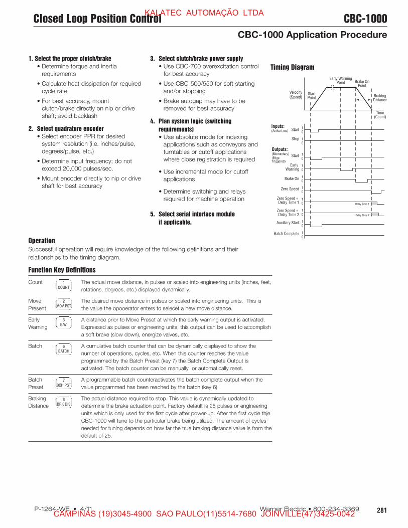
Operation
Successful operation will require knowledge of the following definitions and their
relationships to the timing diagram.
Function Key Definitions
Count The actual move distance, in pulses or scaled into engineering units (inches, feet,
rotations, degrees, etc.) displayed dynamically.
Move The desired move distance in pulses or scaled into engineering units. This is
Present the value the opooerator enters to selecet a new move distance.
Early A distance prior to Move Preset at which the early warning output is activated.
Warning Expressed as pulses or engineering units, this output can be used to accomplish
a soft brake (slow down), energize valves, etc.
Batch A cumulative batch counter that can be dynamically displayed to show the
number of operations, cycles, etc. When this counter reaches the value
programmed by the Batch Preset (key 7) the Batch Complete Output is
activated. The batch counter can be manually or automatically reset.
Batch A programmable batch counteractivates the batch complete output when the
Preset value programmed has been reached by the batch (key 6)
Braking The actual distance required to stop. This value is dynamically updated to
Distance determine the brake actuation point. Factory default is 25 pulses or engineering
units which is only used for the first cycle after power-up. After the first cycle thje
CBC-1000 will tune to the particular brake being utilized. The amount of cycles
needed for tuning depends on how far the true braking distance value is from the
default of 25.
1COUNT
2MOV PST
3E.W.
6BATCH
7BCH PST
8BRK DIS
Timing Diagram
Inputs:<(Active Low)
Outputs:<(Momentary)<(Edge <Triggered)
Start<
Stop
Velocity<(Speed)
Time<(Count)
Braking<Distance
Brake On<Point
Early Warning<Point
Start<Point
Start<
Early <Warning<
Brake On<
Zero Speed<
Zero Speed + <Delay Time 1<
Zero Speed + <Delay Time 2<
Auxiliary Start<
Batch Complete 1<0
1<0
1<0
1<0 Delay Time 1
Delay Time 2
1<0
1<0
1<0
1<0
1<0
1<0
1. Select the proper clutch/brake
• Determine torque and inertia
requirements
• Calculate heat dissipation for required
cycle rate
• For best accuracy, mount
clutch/brake directly on nip or drive
shaft; avoid backlash
2. Select quadrature encoder
• Select encoder PPR for desired
system resolution (i.e. inches/pulse,
degrees/pulse, etc.)
• Determine input frequency; do not
exceed 20,000 pulses/sec.
• Mount encoder directly to nip or drive
shaft for best accuracy
3. Select clutch/brake power supply
• Use CBC-700 overexcitation control
for best accuracy
• Use CBC-500/550 for soft starting
and/or stopping
• Brake autogap may have to be
removed for best accuracy
4. Plan system logic (switching
requirements)
• Use absolute mode for indexing
applications such as conveyors and
turntables or cutoff ap pli ca tions
where close registration is required
• Use incremental mode for cutoff
applications
• Determine switching and relays
required for machine operation
5. Select serial interface module
if applicable.
Closed Loop Position Control CBC-1000
CBC-1000 Application Procedure
KALATEC AUTOMAÇÃO LTDA
CAMPINAS (19)3045-4900 SAO PAULO(11)5514-7680 JOINVILLE(47)3425-0042
Page 22
282 Warner Electric • 800-234-3369 P-1264-WE • 4/11
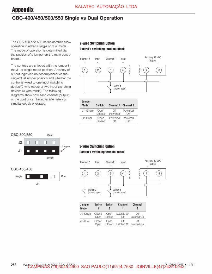
3-wire Switching Option
Control’s switching terminal block
Jumper Switch Switch Channel Channel
Mode 1 2 1 2
J1–Single Closed Open Latched On OffOpen Closed Off Latched On
J2–Dual Closed Open Off OffOpen Closed Latched On Latched On
2-wire Switching Option
Control’s switching terminal block
Jumper
Mode Switch 1 Channel 1 Channel 2
J1–Single Open Off PoweredClosed Powered Off
J2–Dual Open Powered PoweredClosed Off Off
The CBC 400 and 500 series controls allow
operation in either a single or dual mode.
The mode of operation is de ter mined via
the position of a jumper on the main control
board.
The controls are shipped with the jumper in
the J1 or single mode position. A variety of
output logic can be ac com plished via the
single/dual jumper position and whether the
control is wired to one input switching
device (2-wire mode) or two input switching
devices (3-wire mode). The following
diagrams show how each channel (output)
of the control can be either al ter nate ly or
si mul ta neous ly en er gized.
J2
J1
Dual
Jumper
Single
J1
DualSingle
CBC-400/450
CBC-500/550
< Channel 2< Input< Channel 1< Input<
< +< –< +< –
Switch 1<(shown open)
<Auxiliary 12 VDC<
Supply<+< –
* 1* 2* 3* 4 * 7* 8
< Channel 2< Input< Channel 1< Input<
< +< –< +< –
Switch 1<(shown open)
Switch 2<(shown open)
<Auxiliary 12 VDC<
Supply<+< –
* 1* 2* 3* 4 * 7* 8
Appendix
CBC-400/450/500/550 Single vs Dual Operation
KALATEC AUTOMAÇÃO LTDA
CAMPINAS (19)3045-4900 SAO PAULO(11)5514-7680 JOINVILLE(47)3425-0042
Page 23
283P-1264-WE • 4/11 Warner Electric • 800-234-3369
1. What transformers can be used with con trols requiring 24-30
VAC input?
Part
Manufacturer Number Pri ma ry Secondary
Abbott 6B 12-160 115 VAC 24V @ 6 amps
Quality 6-K-119VBR 115/230 VAC 24V @ 8 amps
Signal 24-6 115 VAC 24V @ 6 amps
Signal DP24-6 115/230 VAC 24V @ 6 amps
Triad F-260-U 115 VAC 24V @ 6 amps
2. When a single clutch or brake is used with a
CBC-200 and no switch is used, a jumper wire is required
across terminals 5 & 6 to get output at terminals 4 & 5.
3. What is the difference between a MCS-801 and
a CBC-801-1 or between a MCS-103 and a
MCS-103-1?
There is no performance difference between the
MCS-103 and MCS-103-1. There is no per for mance
difference between the MCS-801 and CBC-801-1. The
CBC-801-1 is roughly 1/4” shorter than the MCS-801. The
units wire and work exactly the same.
4. Which power supplies can be used with the
SF 1525HT and SFC 1525HT coil?
The SF and SFC 1525 High Torque clutch coils require .794
amps of current to provide full rated torque. The following
power supplies and controls will provide the needed power.
CBC-100 .8 amps CBC-450 1 amp
CBC-150 .8 amps MCS-103-1 1.25 amps
CBC-801 1.25 amps CBC-500 1 amp
CBC-400 1 amp CBC-550 1 amp
5. Can I use a CBC-160 with a variable frequency drive and AC
motor?
No. As the voltage to the drive is varied, the output to the
electrically released brake would also vary. This would cause
the brake to re-engage when it should be released.
6. Which power supplies offer a 12 VDC power source that could
be used to power auxiliary switch inputs such as inductive or
photoelectric sensors?
CBC-400, CBC-450, CBC-500,
CBC-550, CBC-700, CBC-750
7. Is the CBC-1000 a stand-alone control?
No. The CBC-1000 provides closed loop feedback for a
clutch/brake system. A common system will consist of four
com po nents:
• a Warner Electric brake and clutch
• a Warner Electric power supply
• an Encoder
• a CBC-1000 position control
The application criteria will determine which clutch/brake and
which control will be appropriate selections.
8. Which of the controls would allow for the
independent operation of two clutches or
two brakes?
Four controls allow for completely independent operation of
two clutches or brakes. That is, that a clutch and brake can
both be on at once, both off at once, or one on and one off.
These controls are:
CBC-801-1 and CBC-801-2, MCS-103-1,
CBC-200, CBC-300
The CBC-400/450 and CBC-500/550 allow for operation of
both channels on at once, both channels off at once or
cycling between channel one and two. However, in the both-
on/both-off mode, you cannot also do independent single
channel operation.
9. Are there any controls that can be used to control the torque of
a 90 volt clutch or brake
via an analog signal input?
There are two options we offer, a special TCS-200 or a
Bronco drive (B169 or B161s) with a signal follower card.
These units can be configured to provide a variable torque
output for a clutch or brake based on an analog input signal.
Consult the factory for the best solution for your specific
application needs.
10. Which controls can be used with electrically released brakes?
The CBC-160-1 and CBC-160-2 are designed specifically to
use with the conduit box of EM and EUM electrically
released brake designs. The CBC-160-1 and CBC-160-2
can also be used with ER and FB brake designs.
The MCS-103-1, CBC-200, CBC-300 and CBC-500/550
can all be used with ER, FB as well as UM-FBC, EM and
EUM-FBB and EM and EUM-MBFB designs.
The MCS 805-1 and MCS 805-2 are for use only with the
ER 1225 brakes. The ERS series brakes can be used with
the CBC-100 or CBC-801 power supplies.
coil
jumper wire
4* 5* 6
Questions and AnswersKALATEC AUTOMAÇÃO LTDA
CAMPINAS (19)3045-4900 SAO PAULO(11)5514-7680 JOINVILLE(47)3425-0042
Page 24
284 Warner Electric • 800-234-3369 P-1264-WE • 4/11
Model Part Number Page
CBC-100-1 ..................................................................6003-448-101 ....................264
CBC-100-2 ..................................................................6003-448-103 ....................264
MCS-103-1 ..................................................................6010-448-002 ....................270
CBC-150-1 ..................................................................6004-448-001 ....................264
CBC-150-2 ..................................................................6004-448-002 ....................264
CBC-160-1 ..................................................................6013-448-001 ....................265
CBC-160-2 ..................................................................6013-448-002 ....................265
MCS-153-1 ..................................................................6012-448-001 ....................271
CBC-200 ......................................................................6011-448-002 ....................272
CBC-300 ......................................................................6021-448-001 ....................272
CBC-400-24 ................................................................6006-448-002 ....................268
CBC-400-90 ................................................................6006-448-003 ....................268
CBC-450-24 ................................................................6006-448-005 ....................269
CBC-450-90 ................................................................6006-448-006 ....................269
CBC-500-24 ................................................................6024-448-002 ....................273
CBC-500-90 ................................................................6024-448-003 ....................273
CBC-550-24 ................................................................6024-448-005 ....................274
CBC-550-90 ................................................................6024-448-006 ....................274
CBC-1825R ..................................................................1825-448-001 ....................276
CBC-700-24 ................................................................6042-448-002 ....................277
CBC-700-90 ................................................................6042-448-003 ....................277
CBC-700 Enclosure ......................................................6042-101-004 ....................277
CBC-750-6 ..................................................................6041-448-001 ....................278
CBC-750-24 ................................................................6041-448-002 ....................278
CBC-750-90 ................................................................6041-448-003 ....................278
CBC-801-1 ..................................................................6001-448-004 ....................266
CBC-801-2 ..................................................................6001-448-006 ....................266
Octal Socket, Foot Mount ............................................6001-101-001 ....................266
Octal Socket, DIN Rail Mount........................................6001-101-002 ....................266
CBC-802-2 ..................................................................6002-448-001 ....................267
CBC-1000 ....................................................................6060-448-001 ....................280
Serial Interface Module..................................................6060-101-232 ....................280
Encoder Cable (Accessory) ..........................................6060-101-001 ....................280
Encoder Cable (Accessory) 7 Pin for marker ................6060-101-002 ....................280
Encoders: 100 PPR ......................................................6060-101-010 ....................280
250 PPR ......................................................6060-101-025 ....................280
600 PPR ......................................................6060-101-060 ....................280
600 PPR w/ marker ....................................6060-101-061 ....................280
1200 PPR ....................................................6060-101-120 ....................280
2500 PPR ....................................................6060-101-250 ....................280
5000 PPR ....................................................6060-101-500 ....................280
Optional Enclosure: CBC-400, CBC-500, CBC-700 ....6042-101-004 ....................268
Optional Enclosure CBC-450, CBC-550 ......................6006-101-007 ....................269
Ordering InformationKALATEC AUTOMAÇÃO LTDA
CAMPINAS (19)3045-4900 SAO PAULO(11)5514-7680 JOINVILLE(47)3425-0042
Page 25
The power of one, the strength of many.
Other product solutions from
Altra Industrial Motion
Our comprehensive product offering is comprised of nine major
categories including electromagnetic clutches and brakes, heavy duty
clutches and brakes, overrunning clutches, gearing, engineered
couplings, engineered bearing assemblies, linear products and
belted drives. With thousands of product solutions available, Altra
provides true single source convenience while meeting specific customer
requirements. Many major OEM’s and end users prefer Altra products as
their No.1 choice for performance and reliability.
Electromagnetic
Clutches and Brakes
Warner Electric
Inertia Dynamics
Matrix International
Heavy Duty
Clutches and Brakes
Wichita Clutch
Twiflex Limited
Industrial Clutch
Overrunning
Clutches
Formsprag Clutch
Marland Clutch
Stieber Clutch
Engineered Couplings
and Universal Joints
TB Wood’s
Ameridrives Couplings
Ameridrives Power Transmission
Bibby Transmissions
Belted Drives
and Sheaves
TB Wood’s
Gearing
Boston Gear
Nuttall Gear
Delroyd Worm Gear
Linear Products
Warner Linear
Engineered
Bearing Assemblies
Kilian Manufacturing
Precision Couplings
and Air Motors
Huco Dynatork
www.altramotion.com
KALATEC AUTOMAÇÃO LTDA
CAMPINAS (19)3045-4900 SAO PAULO(11)5514-7680 JOINVILLE(47)3425-0042
Page 26
Altra Industrial Motion
www.warnerelectric.com
31 Industrial Park RoadNew Hartford, CT 06057 - USA815-389-3771 Fax: 815-389-2582
All Customer Service phone numbers shown in bold
P-1264-WE 4/11 Printed in USA
Heavy Duty Clutches and Brakes
Overrunning Clutches
Formsprag Clutch
Overrunning Clutches and Holdbacks
Warren, MI - USA1-800-348-0881– Press #1
For application assistance:
1-800-348-0881 – Press #2
Marland Clutch
Roller Ramp and Sprag Type Overrunning Clutches and Backstops
South Beloit, IL - USA1-800-216-3515
Stieber Clutch
Overrunning Clutches and Holdbacks
Heidelberg, Germany+49 (0) 6221 30 47 0
Belted Drives and Sheaves
TB Wood’s
Belted Drives
Chambersburg, PA - USA1-888-829-6637 – Press #5
For application assistance:
1-888-829-6637 – Press #7
Engineered Bearing Assemblies
Kilian Manufacturing
Engineered Bearing Assemblies
Syracuse, NY - USA1-315-432-0700
For information concerning our
sales offices in Asia Pacific
check our website
www.altramotion.com.cn
Electromagnetic Clutches and Brakes
Warner Electric
Electromagnetic Clutches and Brakes
New Hartford, CT - USA1-800-825-6544
For application assistance:
1-800-825-9050
St Barthelemy d’Anjou, France+33 (0) 2 41 21 24 24
Precision Electric Coils and Electromagnetic Clutches and Brakes
Columbia City, IN - USA1-260-244-6183
Matrix International
Electromagnetic Clutches and Brakes, Pressure Operated Clutches and Brakes
Brechin, Scotland+44 (0) 1356 602000
New Hartford, CT - USA1-800-825-6544
Inertia Dynamics
Spring Set Brakes; Power On andWrap Spring Clutch/Brakes
New Hartford, CT - USA1-800-800-6445
Linear Products
Warner Linear
Linear Actuators
Belvidere, IL - USA1-800-825-6544
For application assistance:
1-800-825-9050
St Barthelemy d’Anjou, France+33 (0) 2 41 21 24 24
Couplings
Ameridrives Couplings
Mill Spindles, Ameriflex,Ameridisc
Erie, PA - USA1-814-480-5000
Gear Couplings
San Marcos, TX - USA1-800-458-0887
Bibby Transmissions
Disc, Gear, Grid Couplings, Overload Clutches
Dewsbury, England+44 (0) 1924 460801
Boksburg, South Africa+27 11 918 4270
TB Wood’s
Elastomeric Couplings
Chambersburg, PA - USA1-888-829-6637– Press #5
For application assistance:
1-888-829-6637 – Press #7
General Purpose Disc Couplings
San Marcos, TX - USA1-888-449-9439
Ameridrives Power Transmission
Universal Joints, Drive Shafts, Mill Gear Couplings
Green Bay, WI - USA1-920-593-2444
Huco Dynatork
Precision Couplings and Air Motors
Hertford, England+44 (0) 1992 501900
Charlotte, NC - USA 1-800-825-6544
Wichita Clutch
Pneumatic Clutchesand Brakes
Wichita Falls, TX - USA1-800-964-3262
Bedford, England+44 (0) 1234 350311
Twiflex Limited
Caliper Brakes and Thrusters
Twickenham, England+44 (0) 20 8894 1161
Industrial Clutch
Pneumatic and Oil ImmersedClutches and Brakes
Waukesha, WI - USA1-262-547-3357
Gearing
Boston Gear
Enclosed and Open Gearing, Electrical and Mechanical P.T. Components
Charlotte, NC - USA1-800-825-6544
For application assistance:
1-800-816-5608
Bauer Gear Motor
Geared Motors
Esslingen, Germany+49 (711) 3518-0
Nuttall Gear andDelroyd Worm Gear
Worm Gear and Helical Speed Reducers
Niagara Falls, NY - USA1-716-298-4100
KALATEC AUTOMAÇÃO LTDA
CAMPINAS (19)3045-4900 SAO PAULO(11)5514-7680 JOINVILLE(47)3425-0042