www.eae.com.tr 25A...63A Lighting and Small Power Busbar Trunking Cakmakli Mahallesi, 2. Cadde, 119. Sokak, No:12 34522 Kirac-Hadimkoy-Istanbul-TURKEY Tel: +90 (212) 886 23 90 Fax: +90 (212) 886 24 20 T E ME 04 IEC 60439-2 s ISO 9001 14001 N TA L E M M A N N O A R G I E V M N E E N D T N S A Y Y S T I T L E A M U S Q EAE has full right to make any revisions or chances on this catalogue without any prior notice. ATA LTD. / A.C.E./ 612 40 66 Cataloque 06-Ing. / Rev. 03 500 Pcs 04/05/2009
Transcript
www.eae.com.tr
25A...63A Lighting and Small Power Busbar TrunkingCakmakli Mahallesi, 2. Cadde,119. Sokak, No:12 34522Kirac-Hadimkoy-Istanbul-TURKEYTel: +90 (212) 886 23 90Fax: +90 (212) 886 24 20
T E
ME 04
IEC 60439-2 s ISO 900114001
NTAL E MM AN NO AR GI EV MNE E ND TN SA YY STI TL EA M
U SQ
EA
E h
as
full
rig
ht
to m
ake
an
y re
visi
on
s o
r ch
an
ces
on
th
is c
ata
log
ue w
itho
ut
an
y p
rio
r n
otic
e.
ATA
LT
D.
/ A
.C.E
./ 6
12
40
66
Cata
loq
ue
06-I
ng
. /
Re
v. 0
3
500 P
cs
04/0
5/2
009
w w w . e a e . c o m . t r
CONTENTS
General Description
KAM Standard Busbars
KAM Standard Elements
KAM Tap Off Plugs
KAP Standard Busbars
KAP Standard Elements
KAP Tap Off Plugs
Fixing and IP Accessories
Technical Characteristics
Product Overview
2-3
4
5
6
7
8
9
10
11
12
E KAM/KAPLINE
L1
L2
L3
N
E L E K T R Ý K
2 3
KAM and KAP are busbar trunking systems, for
lighting (KAM) and small Power (KAP), designed and
certified in full compliance with international
standards IEC 60439-1 and 2 and IEC 60529. Both
systems have been tested and certified at the CESI
Institute in accordance with the full type test cycle
stated in the relevant IEC codes.
3000750
0 0 0 0
750 750375 375
KAM and KAP Busbar Systems
Feeder units are available for installing at either end
of the system or as a centre feed unit. The feeder units are IP55 as standard, and will
accept supply cables up to ø16mm. The feeder units are supplied in kits including end closure and joint
cover.
Feeder Units
General Characteristics
The joint is a fast locking type with a single screw.
The joint contacts are silver plated and highly
oversized in comparison with the nominal current to
bear in total safety possible short term current
peaks. The joint is further reinforced with tightening
springs which ensures the proper contact pressure
between the conductors. The joint provides
continuity of the housing when used as the earth
conductor.
Joint
General Description
The housing is constructed in pregalvanised sheet
metal which provides a substantial earth path. The
housing gives to the line a very high mechanical
strength, particularly suitable for industrial
application and applications in severe climatic
conditions. The conductors are in electrolytic
copper, tin plated and insulated along their full
length (except at tap off positions) with a self
extinguishing plastic sleeve. 2 and 4 conductor
versions are standard ,with 3 or 5 conductor versions
supplied upon request. Each 3 m standard straight
length is provided with 4 tap off points at 75 cm
distance on one side of the trunking.
Tap off plugs are available in ratings from 10A to 32A. The plugs are manufactured in a
self extinguishing material. The contacts for the phase and neutral conductors are
silver plated copper to provide the best conductivity and resistance to corrosion. The
tapping units for the KAM and KAP busbar systems have different plug-in
configurations and are not interchangeable. All plugs are equipped with a separate
earth contact and is the first to make and and the last to break. The plugs have been
tested at CESI Laboratories for 50 connection disconnection duty cycles. The tapping
units when plugged into the system provides both a good contact with the main
conductors and a secure fixing of the plug on the housing.
KAM 10B are single phase plugs, with fixed phase, without fuses, prewired with cable,
cross section 3x1.5 mm² and length 1m. They can be supplied with different length
cable on request.
KAM 16 K and KAP 16 K are single phase plugs with fixed phase, available with or
without fuse holders. A three phase version is also available, and can be used as a
phase selectable unit for single phase operations. They can be wired with cables up to
a maximum of Ø11 mm.
KAP 32 is a three-phase tap off box, available with fuse holder or with DIN rail to accept
standard modular MCB's.
10A Tap Off Plugs (Only for KAM)
16A Tap Off Plugs
Tap Off Plugs
32A Tap Off Box (Only For KAP)
E KAMLINE 25/32
N
L3
L2
L1
35
55
96402
96400
96373
96372
96406
96404
96375
96374
5
4
3
2
5
4
3
2
25
32
3000750
0 0 0 0
750 750375 375
E L E K T R Ý K
4
Standard Elements
Standard Busbars
Phase Order CodeConductorsCurrent (A) Desc r ip t i on
L1, L2, L3, N, (PE+Housing)
L1, L2, L3, N, (+Housing)
L2, N, (PE+Housing)
L2, N, (+Housing)
L1, L2, L3, N, (+Housing)
L2, N, (PE+Housing)
L2, N, (+Housing)
L1, L2, L3, N, (PE+Housing)
KAM 0205
KAM 0204 Standard Busbar
KAM 0203 Standard Busbar
KAM 0202 Standard Busbar
Standard Busbar
KAM 0305 Standard Busbar
KAM 0304 Standard Busbar
KAM 0303 Standard Busbar
KAM 0302 Standard Busbar
*Special straight length busbars are manufactured as standard as 1 m., 1,5 m. and 2 m.
* With PE Conductor and M25 Gland as standard. End Closer is supplied together with the feeder unit.
E KAMLINE 25/32
75
10
8
200 60160
M25
10
8
200 75 60
M25
160
35924
35925
96413
96412
96411
96410
96409
96408
KAM 0205KAM 0204KAM 0203KAM 0202
KAM 0205KAM 0204KAM 0203KAM 0202
KAM 0205KAM 0204KAM 0203KAM 0202
KAM 0205KAM 0204KAM 0203KAM 0202
KAM 0305KAM 0304KAM 0303KAM 0302
KAM 0305KAM 0304KAM 0303KAM 0302
KAM 0305KAM 0304KAM 0303KAM 0302
KAM 0305KAM 0304KAM 0303KAM 0302
32
32
32
32
25
25
25
25
E L E K T R Ý K
5
Feeder Box*
Busbars Order Code
KAM 0305 BBFeeder Box
KAM 0205 BBFeeder Box
Current (A) Desc r ip t i on
Standard Elements
Feeder Box
End Feeder Box*
Central Feeder Box*
Flexible Elbow
KAM 0305-FDFlexible Elbow
KAM 0205-FDFlexible Elbow
KAM 0305 BOCentral Feeder Box
KAM 0205 BOCentral Feeder Box
KAM 0305 BSEnd Feeder Box
KAM 0205 BSEnd Feeder Box
Busbars
Busbars
Busbars
Order Code
Order Code
Order Code
Current (A)
Current (A)
Current (A)
Desc r ip t i on
Desc r ip t i on
Desc r ip t i on
Central Feeder Box
End Feeder Box
Flexible Elbow
565
16
5
70
48
40
KAM 16 FSKAM 16 K
67696
67695
67694
67693
67700
67699
67698
67697
-
-
-
-
-
-
-
L1, N, PE
L2, N, PE
L3, N, PE
L1, L2, L3, N, PE
L1, N, PE
L2, N, PE
L3, N, PE
L1, L2, L3, N, PE
KAM 16 - FS L1
KAM 16 - FS Tap Off Plug L2
KAM 16 - FS Tap Off Plug L3
KAM 16 - FS Tap Off Plug L123
Tap Off Plug
KAM 16 - K L1
KAM 16 - K Tap Off Plug L2
KAM 16 - K Tap Off Plug L3
KAM 16 - K Tap Off Plug L123
Tap Off Plug
4022
16
16
E L E K T R Ý K
6
E KAMLINE 25/32
Tap Off Plugs
Order CodeCurrent (A) Phase PropertiesDesc r ip t i on Cable Length
*
L1, N, PE
L2, N, PE
L3, N, PE
10
Tap Off Plugs
Tap Off Plugs
Order Code
* Plugs with different length cable available upon request.
KAM 10 - B L1*
KAM 10 - B Tap Off Plug L2*
KAM 10 - B Tap Off Plug L3*
Tap Off Plug
Current (A) Phase PropertiesDesc r ip t i on
1 m. TTR Cable
1 m. TTR Cable
1 m. TTR Cable
Cable Length
With Black Cover
With Yellow Cover
With Blue Cover
Without Fuses.Max diameterof feeder cableis ø11mm.
With 5x20 fuseholders. Maxdiameter of feedercable is ø11mm.
66921
66920
66919
68
74
KAM 10 B
66
105
96422
96420
96424
96425
96418
96416
96426
96427
5
4
3
2
5
4
3
2
40
63
N
L1
L2
L3
35
55
3000750
0 0 0 0
750 750375 375
E L E K T R Ý K
7
E KAPLINE 40/63
Standard Busbars
Current (A) Conductors PhaseDesc r ip t i on
L1, L2, L3, N, (+Housing)
L2, N, (PE+Housing)
L2, N, (+Housing)
L1, L2, L3, N, (PE+Housing)
L1, L2, L3, N, (PE+Housing)
L1, L2, L3, N, (+Housing)
L2, N, (PE+Housing)
L2, N, (+Housing)
KAP 0605 Standard Busbar
KAP 0604 Standard Busbar
KAP 0603 Standard Busbar
KAP 0602 Standard Busbar
KAP 0405 Standard Busbar
KAP 0404 Standard Busbar
KAP 0403 Standard Busbar
KAP 0402 Standard Busbar
Order Code
Standard Elements
10
8
200 60160
M32
10
8
200 75 60
M32
160
63
63
63
63
40
40
40
40
96443
96441
KAP 0405KAP 0404KAP 0403KAP 0402
KAP 0405KAP 0404KAP 0403KAP 0402
KAP 0405KAP 0404KAP 0403KAP 0402
KAP 0405KAP 0404KAP 0403KAP 0402
KAP 0605KAP 0604KAP 0603KAP 0602
KAP 0605KAP 0604KAP 0603KAP 0602
KAP 0605KAP 0604KAP 0603KAP 0602
KAP 0605KAP 0604KAP 0603KAP 0602
96447
96444
95881
35922
95878
35923
75
E L E K T R Ý K
8
E KAPLINE 40/63
KAP 0605 BBFeeder Box
KAP 0405 BBFeeder Box
Feeder Box*
Feeder Box
Busbars Order CodeCurrent (A) Des c r ip t i on
Standard Elements
KAP 0605 BSEnd Feeder Box
KAP 0405 BSEnd Feeder Box
End Feeder Box*
End Feeder Box
Busbars Order CodeCurrent (A) Des c r ip t i on
Central Feeder BoxKAP 0605 BO
Central Feeder BoxKAP 0405 BO
Central Feeder Box*
Central Feeder Box
Busbars Order CodeCurrent (A) Des c r ip t i on
* With PE Conductor and Special EAE Gland M32 as standard.
KAP 0605-FDFlexible Elbow
KAP 0405-FDFlexible Elbow
Flexible Elbow
Busbars Order CodeCurrent (A) Desc r ip t i on
Flexible Elbow
565
16
5
70
66
105
E L E K T R Ý K
9
E KAPLINE 40/63Tap Off Plugs
Tap Off Plugs
Tap Off Plugs
66928
66927
66926
66929
66924
66923
66922
66925
KAP 16 - FS L1
KAP 16 - FS Tap Off Plug L2
KAP 16 - FS Tap Off Plug L3
KAP 16 - FS Tap Off Plug L123
Tap Off Plug
KAP 16 - K L1
KAP 16 - K Tap Off Plug L2
KAP 16 - K Tap Off Plug L3
KAP 16 - K Tap Off Plug L123
Tap Off Plug
L1, N, PE
L2, N, PE
L3, N, PE
L1, L2, L3, N, PE
L1, N, PE
L2, N, PE
L3, N, PE
L1, L2, L3, N, PE
16
16
48
40
KAP 16 FSKAP 16 K
228
11
3
228
11
3
KAP 32
KAP 32 FS
96473
96470
* Tap off box can be fitted with MBC's of different ratings and brands.
L1, L2, L3, N, PE
L1, L2, L3, N, PE
12590
92
53
32
Order CodeCurrent (A) Phase PropertiesDesc r ip t i on
KAP 32-Empty Tap Off Box*
KAP 32-Tap Off Box 10x38 fuse holders
10 x 38 Fuse holdersMax diameter of feedercable is ø 20 mm.
Order CodeCurrent (A) Phase PropertiesDesc r ip t i on
Without FusesMax diameter of feedercable is ø 11 mm.
5 x 20 Fuse holders.Max diameter of feedercable is ø 11 mm.
98525
98699
98698
96449
98707
74031KAM - KAP Fixing Unit
56
15
17115
ø 7
ø 8
ø 7
KA - TP
80
3037
ø 7,5
KA - TPU
55
4020
ø 7,5
60
25
20
ø 7,5
KA - TPL
95
3540
ø 9
ø 12
1
2 3
E L E K T R Ý K
10
E KAM/KAPLINE
Order Code
Order Code
KA - TP
KA - TPU TPU Fixing unit “U” type
KA-TPL Fixing unit “L” type
KA-TD Side Wall Support
KAM-KAP Mechanical Joint Support
Lighting fixture fixing unit
Desc r i p t i on
Desc r i p t i on
Fixing and IP Accessories
Fixing and IP Accessories
Fixing and IP Accessories
Mechanical Joint SupportKA-TD Side Wall Support
To Ceiling
To Floor
To Wall
11
V
Hz
kA
kA
kA
m / m
m / m
m / m
m / m
m / m
m / m
W / m
mm
mm
mm
kg/m
kg/m
rms
2
2
2
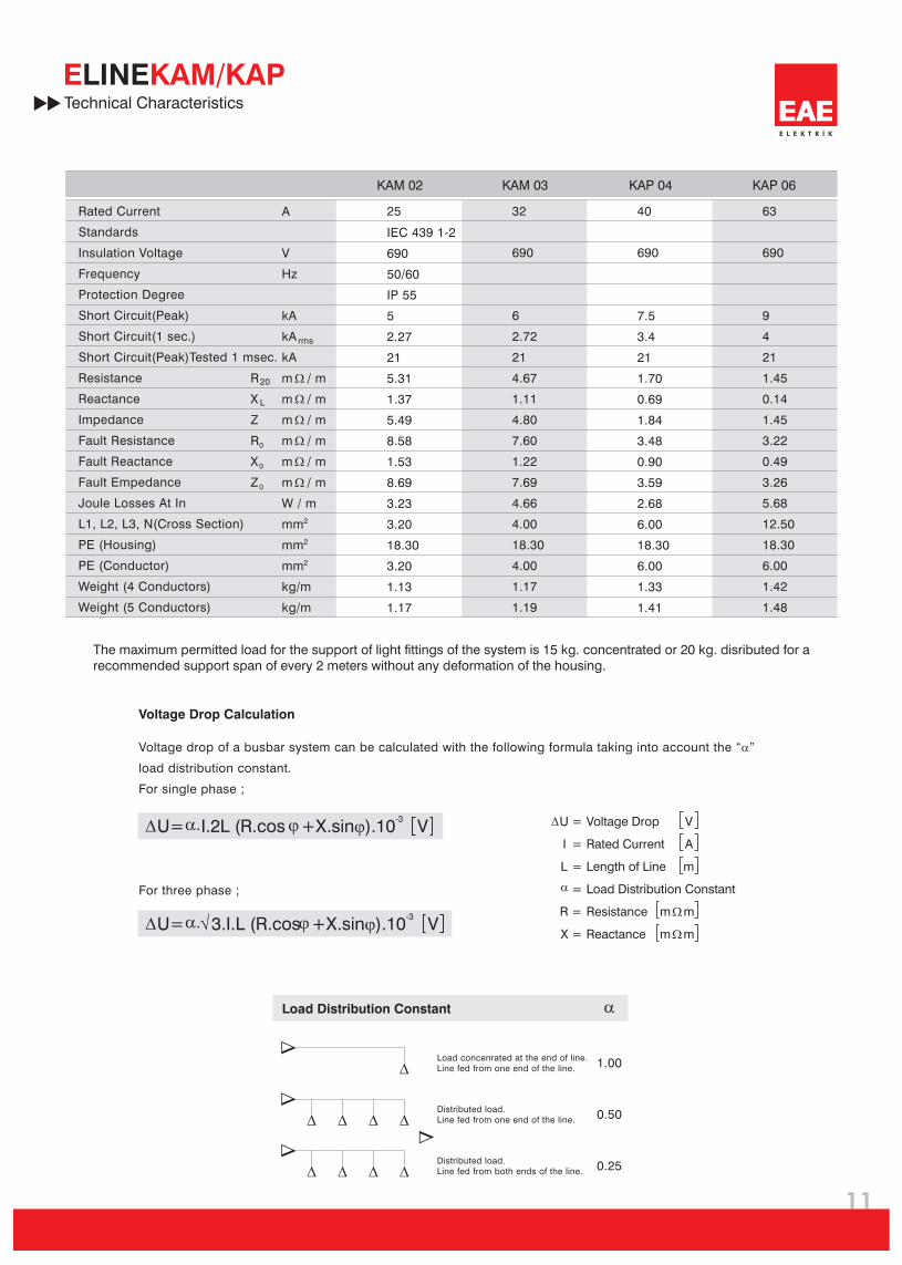
KAM 02 KAM 03 KAP 04 KAP 06
W
W
W
W
W
W
IEC 439 1-2
690
50/60
IP 55
5
2.27
21
5.31
1.37
5.49
8.58
1.53
8.69
3.23
3.20
18.30
3.20
1.13
1.17
6
2.72
21
4.67
1.11
4.80
7.60
1.22
7.69
4.66
4.00
18.30
4.00
1.17
1.19
7.5
3.4
21
1.70
0.69
1.84
3.48
0.90
3.59
2.68
6.00
18.30
6.00
1.33
1.41
9
4
21
1.45
0.14
1.45
3.22
0.49
3.26
5.68
12.50
18.30
6.00
1.42
1.48
A 25 32 40 63
690 690 690
E L E K T R Ý K
E KAM/KAPLINETechnical Characteristics
20
L
R
X
Z
R
X
Z
0
0
0
Rated Current
Standards
Insulation Voltage
Frequency
Protection Degree
Short Circuit(Peak)
Short Circuit(1 sec.)
Short Circuit(Peak)Tested 1 msec.
Resistance
Reactance
Impedance
Fault Resistance
Fault Reactance
Fault Empedance
Joule Losses At In
L1, L2, L3, N(Cross Section)
PE (Housing)
PE (Conductor)
Weight (4 Conductors)
Weight (5 Conductors)
The maximum permitted load for the support of light fittings of the system is 15 kg. concentrated or 20 kg. disributed for a recommended support span of every 2 meters without any deformation of the housing.
U=
U=
I.2L (R.cos
3.I.L (R.cos
V
V
).10
).10
-3
-3
+X.sinj
+X.sinj
D
D
a.
a.
j
jÖ
Voltage Drop Calculation
Voltage drop of a busbar system can be calculated with the following formula taking into account the “a”
load distribution constant.
For single phase ;
For three phase ;
1.00
0.50
0.25
DD
D D
D
DDDD
DDDD
aLoad Distribution Constant
Load concenrated at the end of line.Line fed from one end of the line.
Distributed load.Line fed from one end of the line.
Distributed load.Line fed from both ends of the line.
U =
I =
L =
=
R =
X =
Voltage Drop
Rated Current
Length of Line
Load Distribution Constant
Resistance
Reactance
m
m
m
m
W
W
D
a
V
A
m
12
E L E K T R Ý K
E L E K T R Ý K
E KAM/KAPLINE
25A - 63A PLUG-IN BUSBAR SYSTEMSPRODUCT OVERVIEW
(E-Line KAM / KAP)
1-
2-
3-
4-
5-
6-
7-
8-
9-
10-
11-
12-
13-
The busbar sytem shall have rated current levels between 25A and 63A andshall have copper conductors.
Plug-in busbar system shall have one of the following conductor number andconfigurations;
a) 2 conductors : L1 / N / Housing (Earthing)b) 3 conductors : L1 / N / PE + Housing (PE conductor and housing are connected)c) 4 conductors : L1 / L2 / L3 / N / Housing (Earthing)d) 5 conductors : L1 / L2 / L3 / N / PE + Housing (PE conductor and housing are connected)
Housing shall be used as earth conductor.
The rated insulation voltage of the system shall be 630 V.
On a three meter standard length there shall be four plug-in points.
The conductors in the housing shall be continuously insulated and only peeled offon the plug-in points to create contact area.
There shall be insulator supports at the plug-in points.
The conductors shall be of electrolytic copper and continuously tin plated.
Each current rating of the busbar system shall have a type test report according toIEC 60439/2. The type test reports shall be from an internationally accepted thirdparty laboratory.
Joint of the busbar shall slide into each other; joint contacts shall be silver plated.To ensure a safe joint contact there shall be springs on both sides of jointcontacts.
IP Protection degree of the busbars shall be 55.
The housing of the busbar shall be manufactured of 0,50 mm thick galvanisedsheet metal.
Contacts of the tap offs shall be off jawed structure, which touches the conductorson both sides. The contacts shall also have springs.
Manufacturing facility of busbar systems shall have ISO 9001 and ISO 14001 certification.
Product Overview
Compact Busbar Distribution System800...6300A
Plug-in Busbar Distribution System160...800A
Small Power Plug-in Busbar Distribution System100-160-225A