KAPPA M DS-KAPPAM-1 Radio Modem Module Applicaons Remote networking USB/RS232 cable replacement Remote data log Meter reading Part No Descripon KAPPA-M868 Radio modem module SIL package 868MHz Features Intelligent RF modem module Serial data interface with handshake Host data rates up to 57,600 baud RF Data Rates to 115Kbps Range up to 500m Minimal external components Direct LED drive shows data flow 8 User selectable channels Secure data protocol Ultra low power 2.4 - 3.6V operaon CE compliant for licence free use 868MHz mul channel operaon 20mW transmit power (+13dBm) Receiver sensivity –121dBm The KAPPA modem module is a highly integrated RF modem and intelligent controller with an ultra simple SIL connecon footprint. The KAPPA modem module can achieve a wireless serial data link at up to 38K4bps over 500m range. Range may be further extended with suitable antenna. The user interface is standard RS232, operang at low voltage. All RF operaon is automacally controlled (with error checking etc) so the KAPPA can be treated as a simple communicaons device. Possible applicaons include one-to-one and mul-node wireless links in applicaons in- cluding car and building security, EPOS, inventory tracking, remote industrial process monitoring and computer networking. Because of their small size and low power requirements these modules are ideal for use in portable, baery-powered applicaons such as hand-held terminals. The KAPPA modem module is fully compable with the ZULU series of module modules.
Transcript
KAPPA M
DS-KAPPAM-1
Radio Modem Module
Applications
Remote networking
USB/RS232 cable replacement
Remote data log
Meter reading
Part No Description
KAPPA-M868 Radio modem module SIL package 868MHz
Features
Intelligent RF modem module
Serial data interface with handshake
Host data rates up to 57,600 baud
RF Data Rates to 115Kbps
Range up to 500m
Minimal external components
Direct LED drive shows data flow
8 User selectable channels
Secure data protocol
Ultra low power 2.4 - 3.6V operation
CE compliant for licence free use
868MHz multi channel operation
20mW transmit power (+13dBm)
Receiver sensitivity –121dBm
The KAPPA modem module is a highly integrated RF modem and intelligent controller with an ultra simple SIL connection footprint. The KAPPA modem module can achieve a wireless serial data link at up to 38K4bps over 500m range. Range may be further extended with suitable antenna.
The user interface is standard RS232, operating at low voltage. All RF operation is automatically controlled (with error checking etc) so the KAPPA can be treated as a simple communications device. Possible applications include one-to-one and multi-node wireless links in applications in-cluding car and building security, EPOS, inventory tracking, remote industrial process monitoring and computer networking. Because of their small size and low power requirements these modules are ideal for use in portable, battery-powered applications such as hand-held terminals.
The KAPPA modem module is fully compatible with the ZULU series of module modules.
KAPPA Modem Module
DS-KAPPAM-1
Connections and Mechanical Dimensions
Pin Description
Pin No Name Direction Description
1,11 GND - Ground connections
2 ANT Both Antenna connection 50ohm
3 LED Out TX/RX notification LED
4 CTS Out Low level RS232 CTS
5 RTS In Low level RS232 RTS
6 NC - Do not connect
7 TX Out Low level RS232 data out
8 RX In Low level RS232 data in
9 SLEEP In Sleep pin - take low to enter sleep
10 VCC IN Vcc +2.2 - 3.6V dc
12 NC - Do not connect
AN
T
GN
D
RX
/TX
LE
D
1 2 3 4 5 6 7 8 9 10
11
12
CT
S
RT
S
NC
TX
RX
SL
EE
P
VC
C
GN
D
NC
11
mm
31.5mm
Pin Spacing: 2.54mm / 0.1"
Pin Size: 0.6mm x 0.4mm
4.5
mm
1m
m
KAPPA Modem Module
DS-KAPPAM-1
Connections operational description
Serial Data Format Baud Rate: Set to 19K2 as default Data Bits: 8 Parity: None Stop Bits: 1 Flow Control: Hardware CTS / RTS RX, TX These pins are for data input/output. Data is transmitted and received at the low voltage level (dependent on the Vcc being used). Compatible with LCTTL / LVCMOS. CTS, RTS Clear To Send (CTS) and Request To Send (RTS) are as RS232 standard data flow control used. However they operate at the KAPPA modem modules low level Vcc (3V) If no handshaking is required, (not recommended) RTS may be pulled low. However beware of data overrun errors when transmitting streams of data longer than the data buffer size (57bytes). RESET Connection to GND resets the module. The KAPPA modem module starts when this input is taken from GND to Vcc. Normal operation: connect to Vcc through a 10Kohm resistor. SLEEP Enables ‘Sleep’ mode when connected to ground. For normal operation connect to Vcc. No RF packets will be received by the module when in sleep mode. Tx/Rx LED Direct LED drive which operates whenever there is RF activity.
KAPPA Modem Module
DS-KAPPAM-1
Operation Overview The KAPPA modem module provides a simple interface to the host controller. It handles all RF data communications automatically and without any requirement from the user (RF packetising , preamble, encoding, CRC check etc). With this powerful high-speed radio link, the following networks can be realised:
Networking One-to-One; For point to point data communication
One-to-Many/Broadcast; A network consisting a master and many slaves (all receivers have the same address)
Many-to-One; Where all transmitters with different addresses send to a single receiver address.
Note: Because each KAPPA modem module can be given a unique address, multiple KAPPA networks can co-exist in the same area. This type of operation requires clear timing between transmissions or corruption of packets can occur. Addressing Networks Each KAPPA modem module has a generic pre-configured default address (7F7F7F). This can be modi-fied during configuration. When data received via RF it is examined and the address header embedded within it is compared with its address. Only data received with matching address will be processed and output to the host, all other data will be discarded. When sending data, the KAPPA modem module has a default destination address set to 7F7F7F, this can be user configured. By setting the two addresses appropriately the above network types can be easily achieved.
Operating Modes Configuration Mode: In configuration mode the KAPPA modem module can receive commands to set internal registers to define its eventual operation. In this mode the KAPPA modem module is ‘Offline’ and cannot send or receive RF data. Normal Operation: The KAPPA modem module is ’Online’ automatically transmitting and receiving data from its serial interface across its RF network. Acknowledge Secure Mode : Is not implemented within the KAPPA modem module - however it is a feature of the ZULU Modem Module.
Handshaking The KAPPA modem module required the handshaking (RTS/CTS) to communicate with its host interface. Note: If you do not intend to use handshaking, it is possible to tie the CTS pin to GND and use the modules without. In this configuration the KAPPA modem module will send all data in its buffer after a 10ms timeout. Up to 57bytes can be buffered before data is lost. A minimum of 15ms should be al-lowed before new data is sent to the module after each packet. This is not a recommended method of operation.
KAPPA Modem Module
DS-KAPPAM-1
Configuration Mode (offline)
Commands can be set using a standard terminal program or by sending the relevant ASCII characters. Each command must be followed by the Carriage Return <CR> or ‘Enter’ Note: All commands are entered in upper case
Command Description Response from KAPPA
+++
Enter Configuration Mode
Note: these must be sent as a string with no characters in front or behind. This is to ensure that the +++ is not mistakenly
received in mid-data.
KAPPA responds with status info
? Retrieve the current register values KAPPA responds with all register values
On receiving, the recipient KAPPA Mo-dem will respond with its address and
the level of RSSI (Received Signal Strength)
The Ping command is continuously re-peated every 1 second until any com-
mand or character is entered.
The originating KAPPA modem module will respond with the recipient KAPPA mo-dems’ address. eg. Received from 7F7F7F (D5) Where 7F7F7F = the recipient address D5= RSSI RSSI Is a hex value corresponding to the received signal strength Min = 20hex Max =E0hex
S Save Configuration ‘SAVED’
Q Exit configuration mode and return to No response
KAPPA Modem Module
DS-KAPPAM-1
Register Values (Configuration Mode)
Register Value Range Description Example
R1 0000 - FFFFFF
(24 bit address) Default: 7F7F7F
Sets the recipient KAPPA modem module address
R1=0001 (Data sent to KAPPA Modem module with address 0001)
Set a register: To set a register, type ‘R#=x’ where # is the register number (1-6) and x is the value to set. For example, to set the RF channel to 3 type : R3=3<CR> (Where <CR> is carriage return or enter on the keyboard)
KAPPA Modem Module
DS-KAPPAM-1
Baud rates: It is possible to set both host and RF baud rate via configuration mode. The RF Baud rate should always be twice the host baud rate for best operation.
Unique system identifier Adds a unique identifier at the RF stage. This allows unmatched data packets to be ignored without the need to decode - saving processor time and making a more efficient system when many nodes are pre-sent in one location. Systems with the same identifier will operate together. Use for multiple networks in one location. Do not use addresses: FF, AA or 55.
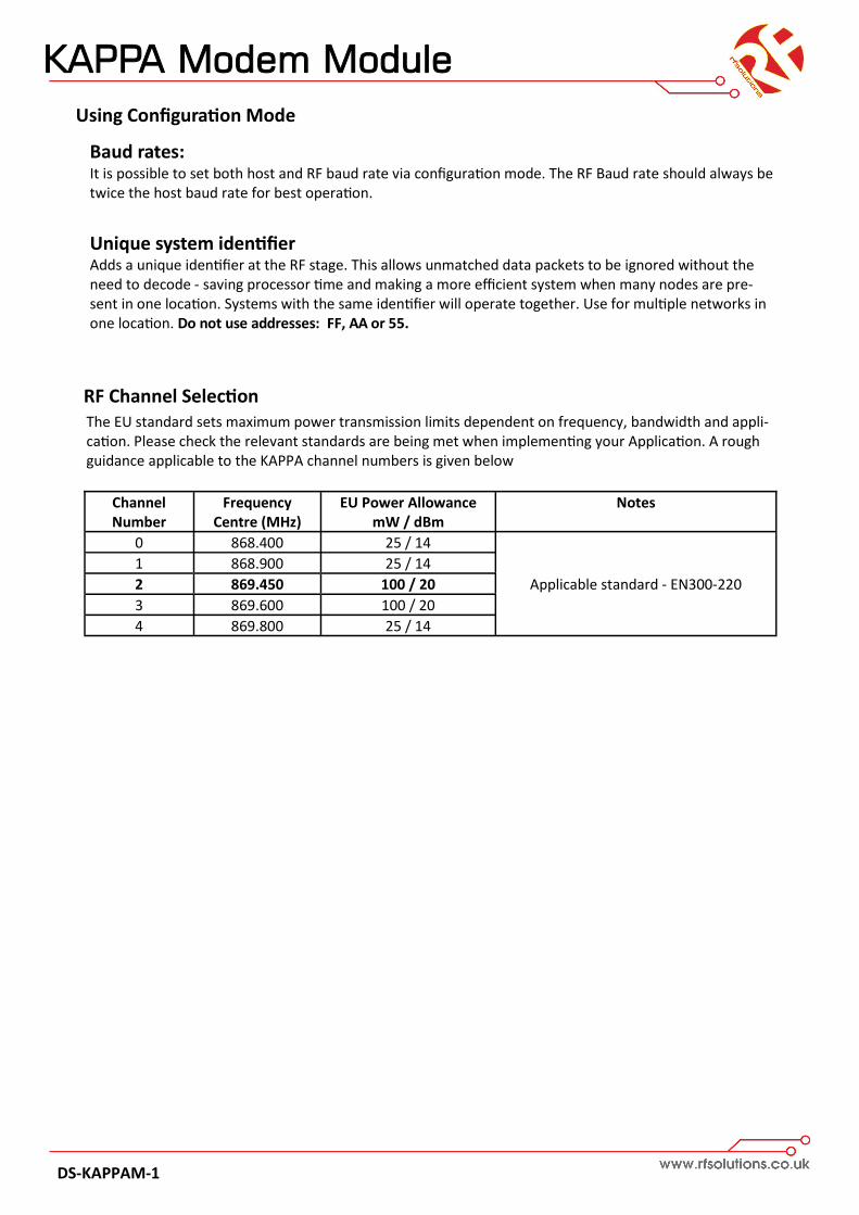
Channel Number
Frequency Centre (MHz)
EU Power Allowance mW / dBm
Notes
0 868.400 25 / 14
Applicable standard - EN300-220
1 868.900 25 / 14
2 869.450 100 / 20
3 869.600 100 / 20
4 869.800 25 / 14
The EU standard sets maximum power transmission limits dependent on frequency, bandwidth and appli-cation. Please check the relevant standards are being met when implementing your Application. A rough guidance applicable to the KAPPA channel numbers is given below
RF Channel Selection
Using Configuration Mode
KAPPA Modem Module
DS-KAPPAM-1
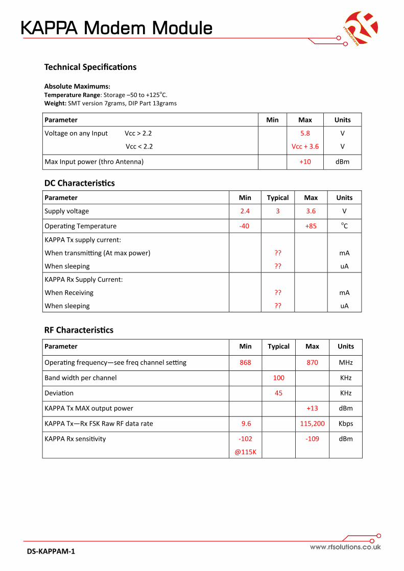
Technical Specifications Absolute Maximums: Temperature Range: Storage –50 to +125oC. Weight: SMT version 7grams, DIP Part 13grams
Whilst the information in this document is believed to be correct at the time of issue, RF Solutions Ltd does not accept any liability whatsoever for its accuracy, adequacy or completeness. No express or implied warranty or representation is given relating to the information contained in this document. RF Solutions Ltd reserves the right to make changes and improvements to the product(s) described herein without notice. Buyers and other users should determine for themselves the suitability of any such information or products for their own particular requirements or specifica-tion(s). RF Solutions Ltd shall not be liable for any loss or damage caused as a result of user’s own determination of how to deploy or use RF Solutions Ltd’s products. Use of RF Solutions Ltd prod-ucts or components in life support and/or safety applications is not authorised except with express written approval. No licences are created, implicitly or otherwise, under any of RF Solutions Ltd’s intellectual property rights. Liability for loss or damage resulting or caused by reliance on the information contained herein or from the use of the product (including liability resulting from negli-gence or where RF Solutions Ltd was aware of the possibility of such loss or damage arising) is excluded. This will not operate to limit or restrict RF Solutions Ltd’s liability for death or personal injury resulting from its negligence.
Reader Response It is our intention to provide you with the best documentation possible to ensure successful use of your RF Solutions product.
If you wish to provide your comments on organization, clarity, subject matter, and ways in which our documentation can better serve you, please email us your comments to the Technical Publications Manager
Application:
Would you like a reply? Y / N
Datasheet: DS-KAPPAM-1
Questions:
1. What are the best features of this document?
2. How does this document meet your hardware and software development needs?
3. Do you find the organization of this document easy to follow? If not, why?
4. What additions to the document do you think would enhance the structure and subject?
5. What deletions from the document could be made without affecting the usefulness?
6. Is there any incorrect or misleading information (what and where)?
R F Solutions Ltd.,
William Alexander House, Willing Way, Burgess Hill
RF Solutions Ltd. Recycling Notice Meets the following EC Directives: DO NOT Discard with normal waste, please recycle. ROHS Directive 2002/95/EC Specifies certain limits for hazardous substances. WEEE Directive 2002/96/EC Waste electrical & electronic equipment. This product must be disposed of through a licensed WEEE collection point. RF Solutions Ltd., fulfils its WEEE obligations by membership of an approved compli-ance scheme.