Karaoke Portable System Lam Hai Dinh, Tuan Dao, and Jennifer Franco Dept. of Electrical and Computer Engineering University of Central Florida, Orlando, Florida, 32816-2450 Abstract — In this paper, a karaoke system, KPS, is proposed. The system will incorporate Bluetooth® 2.0 LS for interconnectivity to multiple devices. Personal videos or an installed application selected from the user’s multimedia database on their device, is utilized as the musical background. A third-party application will be used from the user’s device to obtain lyrics if desired while performing. Additionally, different settings adjust the output in the system. These are bass, treble, echo or delay. Furthermore, open source software is embedded to display an array of LEDs mapped to musical notes based on pitch transcription by use of a frequency detection algorithm. Index Terms — pitch transcription, karaoke, octave, threshold, absolute pitch standard. I. INTRODUCTION Karaoke is a relatively newer form of entertainment in America. Its origins lie within the Asian Market, starting with the first Karaoke machine made in the 1970s. The basic principle of Karaoke is to provide a back tracking for artists or hobbyists to sing songs without the need for a complete band. Karaoke has evolved from a few hundred units being sold in Japan, to having in-home karaoke machines as home theater systems across the globe. With the increasing popularity in American culture, one can often see Karaoke as a form of entertainment in bars and nightclubs. This is often accompanied by lighting effects and multiple monitors to display lyrics to everyone in attendance, including the performer. Karaoke has also been seen in popular video games such as ‘Guitar Hero’ and ‘Rock band’ bringing a gaming entertainment to singing along with popular songs. The Karaoke Portable System (KPS) brings the essence of singing along with numerous songs in a portable package. With the KPS, no longer will it be required to go to a ‘Karaoke Night’ at a bar, or will it be limited to an at-home experience. The KPS will bring the technology of Bluetooth to Karaoke allowing for Karaoke to exist in any moment, and at any time. The Karaoke System will strive to capture an audience of performers or singers with easy to use functionalities. There will be one button for powering the device on and off and will also have the capability of listening to music by connecting to Bluetooth with a mobile device. The overall objective of this project is to have a microphone that combines portable audio and voice into one device for karaoke while maintaining a low-cost design. II. SYSTEM COMPONENTS To have a successful product, each of the components of the system will be designed to work properly together. The components will be either purchased or designed. The technical introduction of each of the components is described in this section. A. Microphone There are several types of microphones, which are determined by different methods of converting the air pressure variations of sound wave into electrical signal. The transformation is when sound waves hit the diaphragm of the microphone. There three common types microphones are dynamic, condenser, and piezoelectric. Finally, the electret condenser microphone is decided to use. An electret condenser microphone (CMC-2742WBL- 25L) from Digi key is the component to use in this project. This microphone is taking analog signals. Electret condenser microphone offers a 60 dB S/N Ratio which helps when already considered error of the component. The input voltage supply varies from 2V (standard) – 10 V (maximum) which helps with the project when the power supplies 3.7 V. This device costs roughly $ 2.42 per unit price and works within a 30 Hz – 15 kHz digital range which is downside of this microphone. One big advantage of this microphone is waterproof, and dust protected. Moreover, the sensitivity is very good for a microphone (-42dB ±3dB @ 94dB SPL). This device is relatively new and meets common day standards [1]. B. Echo Amplifier (PT2399) An echo is a time effect. An echo can take a direct signal and storage it first for a set of small delay time and process it to be played back later [2]. A delay can repeat a signal once or multiple times. It can be used to separate a vocal from the rest of the mix or for a special effect. When applying a large amount of delay time, it can make a sound off. There are two types of echo or delay circuits that humans use in audio system. They are analog and digital echo or delay circuit. PT2399 is chosen in this project because it has both ADC and DAC, also a memory 44 Kbit. The PT2399 is a single chip echo processor IC utilizing CMOS technology
Transcript
Karaoke Portable System
Lam Hai Dinh, Tuan Dao, and Jennifer Franco
Dept. of Electrical and Computer Engineering
University of Central Florida, Orlando, Florida,
32816-2450
Abstract — In this paper, a karaoke system, KPS, is proposed. The system will incorporate Bluetooth® 2.0 LS for interconnectivity to multiple devices. Personal videos or an installed application selected from the user’s multimedia database on their device, is utilized as the musical background. A third-party application will be used from the user’s device to obtain lyrics if desired while performing. Additionally, different settings adjust the output in the system. These are bass, treble, echo or delay. Furthermore, open source software is embedded to display an array of LEDs mapped to musical notes based on pitch transcription by use of a frequency detection algorithm.
Karaoke is a relatively newer form of entertainment in
America. Its origins lie within the Asian Market, starting
with the first Karaoke machine made in the 1970s. The
basic principle of Karaoke is to provide a back tracking for
artists or hobbyists to sing songs without the need for a
complete band. Karaoke has evolved from a few hundred
units being sold in Japan, to having in-home karaoke
machines as home theater systems across the globe. With
the increasing popularity in American culture, one can
often see Karaoke as a form of entertainment in bars and
nightclubs. This is often accompanied by lighting effects
and multiple monitors to display lyrics to everyone in
attendance, including the performer. Karaoke has also
been seen in popular video games such as ‘Guitar Hero’
and ‘Rock band’ bringing a gaming entertainment to
singing along with popular songs. The Karaoke Portable
System (KPS) brings the essence of singing along with
numerous songs in a portable package. With the KPS, no
longer will it be required to go to a ‘Karaoke Night’ at a
bar, or will it be limited to an at-home experience. The
KPS will bring the technology of Bluetooth to Karaoke
allowing for Karaoke to exist in any moment, and at any
time.
The Karaoke System will strive to capture an audience
of performers or singers with easy to use functionalities.
There will be one button for powering the device on and
off and will also have the capability of listening to music
by connecting to Bluetooth with a mobile device. The
overall objective of this project is to have a microphone
that combines portable audio and voice into one device for
karaoke while maintaining a low-cost design.
II. SYSTEM COMPONENTS
To have a successful product, each of the components of
the system will be designed to work properly together. The
components will be either purchased or designed. The
technical introduction of each of the components is
described in this section.
A. Microphone
There are several types of microphones, which are
determined by different methods of converting the air
pressure variations of sound wave into electrical signal.
The transformation is when sound waves hit the diaphragm
of the microphone. There three common types
microphones are dynamic, condenser, and piezoelectric.
Finally, the electret condenser microphone is decided to
use. An electret condenser microphone (CMC-2742WBL-
25L) from Digi key is the component to use in this project.
This microphone is taking analog signals.
Electret condenser microphone offers a 60 dB S/N
Ratio which helps when already considered error of the
component. The input voltage supply varies from 2V
(standard) – 10 V (maximum) which helps with the project
when the power supplies 3.7 V. This device costs roughly
$ 2.42 per unit price and works within a 30 Hz – 15 kHz
digital range which is downside of this microphone. One
big advantage of this microphone is waterproof, and dust
protected. Moreover, the sensitivity is very good for a
microphone (-42dB ±3dB @ 94dB SPL). This device is
relatively new and meets common day standards [1].
B. Echo Amplifier (PT2399)
An echo is a time effect. An echo can take a direct
signal and storage it first for a set of small delay time and
process it to be played back later [2]. A delay can repeat a
signal once or multiple times. It can be used to separate a
vocal from the rest of the mix or for a special effect. When
applying a large amount of delay time, it can make a sound
off. There are two types of echo or delay circuits that
humans use in audio system. They are analog and digital
echo or delay circuit.
PT2399 is chosen in this project because it has both
ADC and DAC, also a memory 44 Kbit. The PT2399 is a
single chip echo processor IC utilizing CMOS technology
which accepts analog audio input signal, a high sample
rate ADC transfer the analog signal into a bit stream then
storage to internal 44Kbit RAM, after processing the bit
stream will de-modulate by DAC and low-pass filter.
Overall delay time is determined by internal VCO clock
frequency, and user can easy to change the VCO frequency
by changing the external resistance [3].
C. Volume Amplifier (LM386)
Speaker are devices that translate signals from an
electronic device, such as a receiver or CD player or sound
waves. Sometimes, the listeners want to get a sound louder
or smaller, then speakers may need a bit of a power boost
to produce louder and cut the power to get sound lower.
Running an amplifier between the audio device and the
speakers will raise the wattage going into the speaker. This
amplifier is called volume amplifier. The connection of the
speaker and preamplifier is important, and without one of
them, the listeners cannot hear any sound. The best
combination of these relationship is to get a pre-amplifier
that has twice wattage of the speaker [4]. For example,
speaker can produce 50 watts, so the amplifier should be
100 watts.
There are two types of volume amplifier. They are
analog and digital volume amplifiers. Finally, LM386 chip
is decided to choose as a volume amplifier from Texas
Instrument (TI). LM386 is a low voltage audio amplifier
and frequently used in battery powered music devices like
radios, guitars, toys etc. The gain range is 20 to 200, gain
is internally set to 20 (without using external component)
but can be increased to 200 by using resistor and capacitor
between PIN 1 and 8, or just with a capacitor. Voltage
gain simply means that Voltage out is 200 times the
Voltage IN. LM386 has a wide supply voltage range 4-
12v. In a special case, the voltage supply can be between
5V-18V if using another LM386 package. There are five
packages for LM386 audio amplifiers. To meet the battery
requirement, the package (LM386N-4) is decided to
choose in this project. In this package, the power output is
enhancing a lot of better than a normal one. Its power
output is between 0.7W-1.3W. The voltage gain (Av) in
typical case is 26 dB (Av=20), and in special case when
putting a polar capacitor 10uf, the voltage gain is 46 dB
(Av=200).
D. Stereo Amplifier:
The amplifier will tone control the audio of your voice.
It has four tone controls option: volume, balance, bass, and
treble. It required 12 volts for power supply to operate.
The stereo amplifier will take the analog audio signal from
echo amplifier, tone control the audio, and send it to post-
amplifier before going to a 10 Watts speaker. It goes up to
20 dB of voltage gain, and +/- 15 dB for Bass and Treble
control. The main part for this amplification process is
TDA1524 op-amp. This integrated circuit is manufactured
by Philips and has a low total harmonic distortion (THD).
E. Bluetooth Module:
For wireless function of the project, Bluetooth
technology is chosen. Ideally, the Bluetooth module has
low power consumption, short range, and small. BK8000L
Bluetooth module is the best fit. It provides high quality
sound and compatibility. Moreover, it has SBC audio
decoding performance, auxiliary connection function as
back up, and the size of a quarter. The digital signal of the
any electronic device will go to the Bluetooth module. It
will convert to analog sign then amplified by LM386
circuit before going to the speakers.
F. Battery:
Lithium-Ion battery will be used to supply for the whole
system. It has high energy density, rechargeable, and low
self-discharge. The LED and the speakers consume a lot of
power. Therefore, the capacity of 9800mAH can make the
KPS to operate 5 hours continuously. In addition, most of
the amplifiers takes 12 volts for power supply. Lithium-
Ion battery could supply that with small size as 5”x3”x1”.
The battery can be recharged by LM3622 circuit. It takes
up to an hour to have the battery fully charged.
G. Speakers:
There are three speakers in the project. Two 4 Ohms, 5
Watts speakers for left and right channels for Bluetooth
module. To balance the volume, one 4 Ohms, 10 Watts
speaker is connected to the microphone.
H. ADC
An Analog to Digital Converter does just as it states. It
takes an analog input (the LED display) and converts it to
a digital value in which the microprocessor can interpret.
However, choosing an ADC isn’t as straight forward as its
functionality. Numerous different specifications are sued
to describe them. Namely Resolution, Accuracy, Sampling
Speed, and Quantizing noise. Resolution is simply the
number of output bits per conversion. Accuracy is how
close the output is in representing the maximum resolution
given. This is usually dictated by noise, and nonlinearities
defined by the ADC itself. Sampling speed is the most
conversions that an ADC can be made per second. And
finally, Quantizing noise is a specific type of noise
(unwanted voltage) that is added to the input [5]. When
researching different ADC’s to use for the VTVD these
parameter specifications will be taken into consideration
for part selection and ADC type. The ADC used for the
system was the ADC121S101, it has one of the highest
resolutions, highest speeds and an affordable price.
I. Microcontroller
A Microcontroller is a small computer on a single
integrated circuit. A microcontroller is designed to govern
specific operation an embedded system. The
microcontroller was used to program the ADC to ensure
proper conversion from an analog signal to a digital signal.
The microcontroller was also used to program the LED
display. The ATmega was an ideal choice for the system.
It is an 8-Bit Atmel chip with high performance. Has high
endurance non-volatile memory segments, an advanced
RISC architecture with 135 instructions and up to 16
MIPS throughput at 16MHz.
III. SYSTEM HARDWARE CONCEPT
All the components were described from the previous
section. The connection of the hardware will be presented
in a block diagram, showing the I/O flow of the system
hardware
Figure 1. Block Diagram Presenting Major Hardware
Components.
There are two inputs going to the system: analog audio
signal from physical voice and digital signal from any
electronic device. First, the analog signal goes to the
electret condenser microphone. Since the signal magnitude
is so small, it then goes to the pre-amplifier circuit. Echo
and Stereo amplifiers would filter the analog signal and
make it sound more professional. However, the signal is
still very low; hence, it will be amplified one more time
before projecting through the front speaker. Secondly, the
Bluetooth module connects to an electronic device. The
digital signal converts to analog signal by the module. The
magnitude of the signal then increases by a sound
amplifier. Finally, left and right speakers will project the
music.
IV. HARDWARE DESIGN
Each of the major system components outlined in
section II, System Components will now be described in
detail.
A. Echo Amplifier (PT2399)
PT2399 echo chip are working in the low power
supply, and they are easy to build than using other IC echo
chips because it has an ADC and DAC that are built inside
the chip. PT2399 is a good chip since the echo and
feedback effects is adjusted by the potentiometers. When
testing this chip PT2399, the designed circuit is testing
multiple times when using this PT2399 echo chip. The
first thing is to make sure the power supply must be low.
The PT2399 is working on the range of supply voltage
(4.5 – 5.5 V). This is met the requirement.
Echo Amplifier requires power supply between 4.5V-
5.5V for its minimum operated limit. This is a challenge
for the project to find the battery that could meet the
requirement. The voltage regulator is used to step down
voltage 5V from the battery 12V. The design of the echo
amplifier is complicated. It has two potentiometers to
adjust the magnitude of each functions: the delay time, and
the feedback. All in all, by using this PT2399 echo chip,
the sound that is recorded from the microphone with the
echo and feedback adjusting by potentiometers, but the
output is still low and small noises, so the volume
amplifier is decided to use for boosting the output.
Moreover, the input signal will decrease tremendously
after being filtered by this amplifier. Therefore, the output
signal need to gain at least 10 dB by another amplifier to
have the sound be hearable. Also, because the output
signal of this echo amplifier is small for human to hear,
this echo amplifier is designed like an affect to change the
signal for delay time, not to change the volume, so this
echo amplifier is put in the middle of two volume
amplifiers.
For the schematic of the echo effect design, the
designed circuit is used with the PT2399 digital chip, and
this chip is a single chip echo processor IC utilizing
CMOS technology which accepts analog audio input
signal, a high sample rate ADC transfer the analog signal
into a bit stream then storage to internal 44Kbit RAM,
after processing the bit stream will de-modulate by DAC
and low pass filter.
Figure 2: PT2399 Echo Amplifier Circuit Diagram
B. Volume Amplifier (LM386)
Volume Amplifier requires power supply between
5V-18V for its minimum operated limit. This meets the
requirements of the battery 12V. The design of the
volume amplifier is complicated. It has two LM386 chips.
The first one is pre-amplifier for the microphone. At this
one, the voltage gain is only designed with the voltage
gain 20. At this stage, the current is so high, that makes the
LM386 getting hotter, so putting another LM386 as
second stage with the voltage gain 200 is a solution for this
problem. At this second stage, using a potentiometer is
designed to adjust the current supply. This potentiometer
is very sensitive since it controls the voltage gain. To
design the whole system for the microphone, the order of
the connection of each amplifier is important, so putting
echo amplifier and stereo amplifier between these two
stages is a solution.
For the schematic of the volume amplifier design,
there are two LM386 chips. The first one is used for pre
amplifier for the microphone, and the second one is used
to amplifier the output of the whole karaoke system. The
IC LM386 is a power amplifier used for amplifying small
audio signals with low supply voltages. Though the gain of
this IC is set at 20 internally, it can be raised almost 10
times higher - that is up to 200, just by introducing a
resistor and a capacitor across its pin 1 and 8. The IC is
available with four versions: LM386 N-1, N-2, N-3 which
typically show very low distortion characteristics and
function well with voltages ranging from 4 to 12 volts DC.
The fourth type, the LM386 N-4, is specified with working
voltages from 5 to 18 VDC, these being the final safe
thresholds beyond which either the devices stop working
or become too hot and get damaged. In this design, there
will be two extra 12V voltage supply for the echo
amplifier and stereo amplifier.
Figure 3: LM386 Volume Amplifier Circuit Diagram
C. Bluetooth Module:
BK8000L Bluetooth Module is 2.1 type with
compliant. The Bluetooth module contains integrated
stereo ADC and DAC, five bands hardware equalizer,
digital equalizer for stereo line in, and integrated full
duplex hands-free speakerphone. The Bluetooth module
also has the function for auxiliary connection in case the
wireless function is not operated. However, the analog
signal is still very low before it goes to the speaker.
Therefore, a small external amplifier using IC chip LM386
will connect with BK8000L. Then the signal will go the
left and right channels through 5 Watts speakers.
D. Battery:
The 9800mAh 12 volts Lithium-Ion battery require a
circuit to charge. IC LM3622 is a powerful chip that could
make a 12.6V, 4A Li-Ion battery charger circuit.
Figure 4. LM3622 Battery Charger Circuit.
The following graphs shows the charging voltages and the
capacity over time of the battery:
Figure 5. Charging characteristic of 9800mAh 12V
battery
Some important values in charging battery are:
1. Input Voltage: 20V
2. Charge Voltage: 14.6V
3. Charging Current: 10000 mA (1 Charge)
By observing both graphs, the battery is fully charge in an
hour and reach 14.6V.
E. Stereo Amplifier:
Stereo Amplifier requires 12 V power supply for its
minimum operated limit. This is a challenge for the project
to find the battery that could meet the requirement. The
design of the stereo amplifier is complicated. It has four
potentiometers to adjust the magnitude of each functions:
Volume, Bass, Treble, and Balance. Moreover, the input
signal will decrease tremendously after being filtered by
this amplifier. Therefore, the output signal need to gain at
least 10 dB by another amplifier to have the sound be
hearable.
TDA1524A chip is manufactured by PHILIPS. It is
designed as an active stereo-tone and volume control,
especially for car radios, TV receivers and mains-fed
equipment. It includes functions for bass and treble
control, volume control with built-in contour (can be
switched off) and balance. All these functions can be
controlled by DC voltages or by single linear
potentiometers. It provides very pleasing performance and
makes a useful addition to any of our audio power
amplifier kits. RCA jacks is optional for audio inputs.
Usually TDA1524A supports for left and right channel;
however, there is only one output to the front speaker, one
channel will be grounded.
Figure 6. TDA 1524A Stereo Amplifier Circuit with
one input and one output.
IV. LED DISPLAY
The LED display will function as an individual unit to
the system. The display is intended to be an enhanced
feature to the Karaoke Portable System. The LED display
is a collection of individual LED lights in which an LED
driver can be accessed to toggle the individual addressable
LED lights on and off to an array of colors. It will add an
esthetically pleasing overall look to the system. Not only
will the Portable system allow the singer to have the ability
to hear their favorite songs but perform to their favorite
songs while an arrangement of lights display the
performance for an exciting and interesting show for all
the enticed viewers watching.
The LED display is responsible for using the incoming
input signal picked up by a microphone or device
(connected to the display) and sampling it to obtain the
frequency and amplitude of the signal to output the proper
display. The LED display will map a specific RGB color
to the 12 notes of the Western scale, read from the ADC.
This feature will allow the performer to receive visual
feedback of the specific notes he or she is singing.
V. FREQUENCY DETECTION ALGORITHM
Accurate frequency detection is important for identifying
the frequency of a signal. Open source software was
written and embedded into the system to display the array
of LEDs. This section explains the code (frequency
detection algorithm) used in the system. To make this
algorithm possible a 12 bit-ADC detected the incoming
Voltage =14.6V
Capacity =100%
signal and converted the input analog signal into a digital
signal. To properly capture the analog signal and make the
conversion to a digital signal, port manipulation was used
and coded in the Arduino IDE for the ATmega2560. The
ports that were available for the ATmega were PORTB
and PORTH. The ADC required a 12bit resolution,
however since the data being read was of a byte data type,
the data needed to be shifted from 16-bits being read in to
12 bits. The ADC has three controls to make the proper
conversion of signals, according to the datasheet. These
are the chip select, clock, and data pins. The first port
(PORTH) was used to enable the ADC by set the chip
select high. PORTB was used to enable the CLOCK while
in a for loop that ran at a size of 16. The data read was
then shifted over to only capture 12 bits of data necessary
for the ADC used in the system. Once this function
completed the data read from the ADC was sent back to
the main program.
Once a digital signal was received, manipulation of the
incoming data being read was mapped to the LED display.
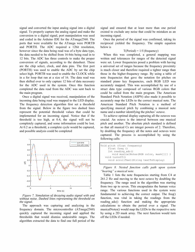
The frequency detection algorithm first set a threshold
from the signal. Below in the figure two dashed lines
represent the potential threshold values that could be
implemented for an incoming signal. Notice that if the
threshold is too high, at 0.4, the signal will not be
completely captured, and some information could be lost.
At 0.2 as a threshold, a complete cycle would be captured,
and possible analysis could be completed
Figure 7. Simulation of decaying audio signal with and
without noise. Dashed lines representing the threshold on the signal.
The approach was capturing and analyzing in the
frequency domain. The microcontroller (ATmega2560)
quickly captured the incoming signal and applied the
thresholds that would dismiss undesirable ranges. The
algorithm extracted the data to find one full period of the
signal and ensured that at least more than one period
existed to exclude any noise that could be mistaken as an
incoming signal.
Once the period of the signal was confirmed, taking its
reciprocal yielded the frequency. The simple equation
below is
T(Period) = 1/f (frequency)
When this was completed, a general mapping was
written and tolerances for ranges of the detected signal
were set. Lower frequencies posed a problem with having
a universal set of ranges because the frequency proximity
is much closer and therefore required a tighter range than
those in the higher-frequency range. By using a table of
note frequencies that gave the notation for pitches on
standard piano key frequencies, each RGB LED was
accurately mapped. This was accomplished by use of a
struct data type composed of various RGB colors that
could be called from the main program. The American
Standard Pitch Notation (ASPN) also made it possible to
accurately map the LEDs to the correct musical note. The
American Standard Pitch Notation is a method of
specifying musical pitch by combining a musical note
name and a number identifying the pitches’ octave.
To achieve optimal display capturing all the octaves was
crucial. An octave is the interval between one musical
pitch and another. The absolute pitch standard is defined
so that all musical Cs are integer powers of 2. Therefore,
by doubling the frequency all the notes and octaves were
captured. The process is accomplished by using the
following calls:
Void pitch (float frequency)
Float freq ()
Int reading_adc()
void musicalNotes(RGB color, mask[][] )
void turnoff()
void scrollText(String textToDisplay)
Figure 8. Nested function calls path upon system
“hearing” a musical note.
Table 1 lists the note frequencies starting from C4 at
261.2 Hz and moving to the next octave by doubling the
frequency. The range used in the algorithm was starting
from two up to seven. This encapsulates the human voice
range. The various functions used in the system were
fundamental to achieving the correct output. The freq()
function, was vital in taking the readings from the
reading_adc() function and making the appropriate
calculations to obtain the period over a signal. The
musicalNotes() would map the LEDs to the respective note
by using a 2D mask array. The next function would turn
off the LEDs if needed.
C C# D Eb E F
0 16.35 17.32 18.35 19.45 20.6 21.83
1 32.7 34.65 36.71 38.89 41.2 43.65
2 65.41 69.3 73.42 77.78 82.41 87.31
3 130.8 138.6 146.8 155.6 164.8 174.6
4 261.6 277.2 293.7 311.1 329.6 349.2
5 523.3 554.4 587.3 622.3 659.3 698.5
6 1047 1109 1175 1245 1319 1397
7 2093 2217 2349 2489 2637 2794
8 4186 4435 4699 4978 5274 5588
Table 1. Summary of Note Frequency (Sample)
VI. CASE DESIGN
The purpose is to build the box that can display all the
components of the system. Acrylic sheets are the best
material option. First, it can be easily laser cut by TI lab
by using AutoCAD to draw the dimension and holes.
Second, acrylic sheets could be assembly easily by acrylic
glue and hardly break. Finally, the committees could see
all the PCBs, components, and wires inside the box.
There are three small boxes for the speakers which will
places on the bottom sheet. The battery also mounted on
the bottom sheet which makes the system has strong
foundation. Next, the PCBs are mounted on the speakers’
box and the potentiometers are placed on the top sheet.
The top and front speakers connect with two clamps so it
can open easily for maintenance. The goose neck
microphone cover is used to cover the microphone. It
delivers the flexibility of the user. The LED display is
placed in front of the box and connect to the top sheet.
Figure 8. The Animation of the Karaoke Portable System
VII. PCB BOARD DESIGN
The complete system, with the obvious the karaoke
system and LEDs display, is implemented on a dual-
planed perforated prototyping connection board. This is
big enough to allow for complex wires and components to
connect on the PCB boards. There are three through-hole
components for our karaoke system and two surface
mounted components for the LED display system. The
reasons that this project has five PCB boars are to fix them
easier. Each PCB board has its own function, so testing
and fixing each PCB are more reliable.
The design of PCB is a highly-efficient method of
prototyping with Eagle-cad and EasyEAD software, and
one that allowed for this system to maintain relatively low-
noise operation. All in all, the PBC boards design meets
the highest accurate in dimensions and good quality to
reduce noise and produce and good quality of music.
VIII. SAFETY AND STANDARDS
Throughout this project, the safety and standard are
very important. First, any heat dissipation from our power
PCB would cause potential injury to the user, so using a
relatively small voltage to accomplish the goals for both
the electret microphones and the overall run-time of the
design is a solution. Second, all potentially between the
connection in wires have been wrapped with heat shrink to
prevent any shock for the user. All wires that run from the
microphone and battery to the power PCB have been
collected and wrapped in heat shrink as to limit the amount
of separate wires in the project.
IX. CONCLUSION
Overall this system was design for the user to sing and
enjoy the music in everywhere. The product is used to be
more amusing in music. The product is made in high
quality of acrylic sheets, and all the components and PCB
are meet the safety and industry standards. The karaoke
system is included the microphone, echo, bass, treble, and
volume control is working perfectly with very low noises.
The music is played from Bluetooth device that work
perfectly. Future work in the design would consist of a
full product prototype, as well as making the smaller to be
more portable.
THE ENGINEERS
Lam Dinh is a 24 -year old
graduating Electrical
Engineering student who is
taking a job with Duke Energy
in Lake Mary, FL, as a
transmission substation engineer,
specializing in grounding
analysis, substation design, and
protection scheme design for
high quality and reliability
performance of substation
systems.
Tuan Dao is a 28 -year old
graduating Electrical
Engineering student. Tuan hopes
to pursue master degree in
electrical engineering after
working for a few years to
obtain the experience. He
specializes in area of sound
engineering: loudspeaker and
amplifier design, working for
company such as Beats by Dre,
Bose, JBL, Sony, or Samsung.
Jennifer Franco is a Computer
and Electrical Engineer, she
hopes to pursue fields in the
software industry. Jennifer
worked on the design of the
LED display and programming
of the Karaoke Portable System.
Upon graduation she has been
giving the offer to work as a
Substation engineer for Duke
Energy.
ACKNOWLEDGEMENT
The authors wish to acknowledge the assistance and
support of the Electrical Engineering department, Dr.
Samuel Richie, Wei Sun, Suboh Suboh, and Michael
Haralambous; University of Central Florida. Special
thanks to T.I. Lab for their assistance in the construction
and testing of this design.
REFERENCES
[1] “CMC-2742WBL-25L Datasheet” CUI INC. June
2008 [2] Wikipedia, “Delay (Audio Effect),” Wiki, August 25,
2017. [online]. Available: https://en.wikipedia.org/wiki/Delay_(audio_effect). [Accessed 28 October 2017].
[3] Princeton Technology Corp, “PT2399 Datasheet,” PTC, February 2010. [online]. Available: http://www.princeton.com.tw/Portals/0/Product/PT2399_1.pdf. [Accessed 10 November 2017].
[4] Joe Roberts, “Audio Power Amplifier Power Rating Mysteries Explained,” Tech Notes, November 01, 2016. [online]. Available: http://www.rocketroberts.com/techart/powerart_a.htm. [Accessed 31 October 2017].