10
KASELOR LTD, Consulting Engineer 81

KASELOR LTD, Consulting Engineer 81

KASELOR LTD, Consulting Engineer 82
GEOTECHNICAL SURVEY Client: Flacq United Estates Limited Location: Providence Date of survey: 19th September 2011 1 INTRODUCTION The proponent, Flacq United Estates Limited, has submitted an application for clearance from the Ministry of Environment in a view to implement a Morcellement for Residential Purposes at Providence. On that basis, Kaselor Ltd, Civil and Structural Engineering, has been appointed by the Promoter to carry out a Geotechnical Survey/Engineering Report for the project. Five trial pits were excavated to carry out percolation tests on the proposed site in order to determine the onsite disposal system. Moreover, the description of the soil strata in the pits are also submitted. A geotechnical survey was carried out for Flacq United Estates Limited on 19th September 2011. The primary goals of the survey are:
� Description of the soil profile down to a depth of 3.0m
� Percolation tests carried out in the pit
� Level of water table 2 SITE GEOLOGY Volcanic deposits which formed the Island through a series of three basaltic lava flows, 8–9 million years ago, 200,000 years ago and 20,000 years ago, respectively, dominate the geology of Mauritius. The soil in the Providence area mostly belongs to the Latosolic Brown Forest soils. The geology of Mauritius is mainly composed of basaltic lavas which originate from volcanic origin. The Food and Agriculture Organisation (FAO) and Mauritius Sugar Industry Research Institute (MSIRI) Land Resources and Agricultural Suitability Map of Mauritius identifies the site for the proposed morcellement for residential purposes as forming part of the late lavas of the younger volcanic series which erupted from a chain of some 20 vents.

KASELOR LTD, Consulting Engineer 83
The FAO/MSIRI map classifies the different regions into land units. The proposed site consists of Land Unit namely 5.6 as indicated on Figure 1A below.
Figure 1A: Site Geology

KASELOR LTD, Consulting Engineer 84
2.1 GEOLOGICAL CHARACTERISTICS The project site falls within Mid-North Central Plateau, East Plateau Intermediate Lava Plains and slopes. These type of soils is characterized as sloping undulating, hummocky and rough. and the soil represent a comparatively shallow to shallow dark brown silty clay loam with frequent, weathered gravels and stones. 3 SITE DESCRIPTION The total project area is situated in the District of Moka. The location plan of the proposed morcellement for residential purposes site is shown on the accompanying drawing at the end of the annexure. All part of the project site is under vegetation as shown on the plates below:
Plates showing project site
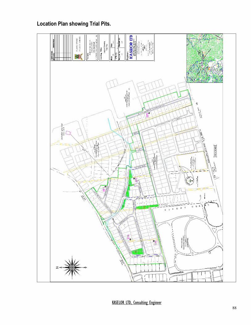
In order to determine the soil profile along with its percolation rates, five trial pits of approximate depth of 3.0m have been excavated for the site. The location of the pits is indicated in the accompanying layout plan at the end of the annexure. 4 SOIL PROFILING A typical soil profile is provided at the end of the annexure.
KASELOR LTD, Consulting Engineer 85
In general, A horizon is identified as a dark brown silty clay of about 250mm and is of higher organic matter content. This layer then merges into a reddish brown silty clay mixed with fractured basalt, namely B horizon, which goes down to a depth of 1200 mm. The next layer is characterized by reddish blue fractured bedrock which goes to a depth of more than 3.0m.
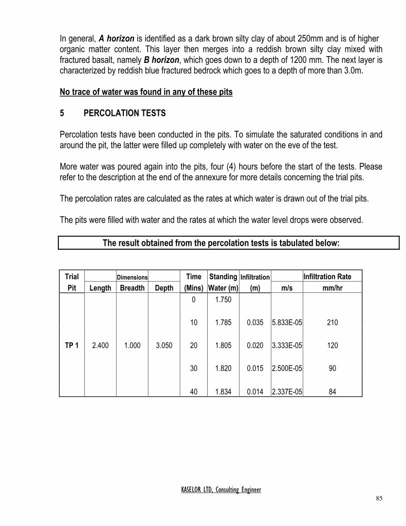
No trace of water was found in any of these pits 5 PERCOLATION TESTS Percolation tests have been conducted in the pits. To simulate the saturated conditions in and around the pit, the latter were filled up completely with water on the eve of the test. More water was poured again into the pits, four (4) hours before the start of the tests. Please refer to the description at the end of the annexure for more details concerning the trial pits. The percolation rates are calculated as the rates at which water is drawn out of the trial pits. The pits were filled with water and the rates at which the water level drops were observed.
The result obtained from the percolation tests is tabulated below:
Trial Dimensions Time Standing Infiltration Infiltration Rate
Pit Length Breadth Depth (Mins) Water (m) (m) m/s mm/hr
0 1.750
10 1.785 0.035 5.833E-05 210
TP 1 2.400 1.000 3.050 20 1.805 0.020 3.333E-05 120
30 1.820 0.015 2.500E-05 90
40 1.834 0.014 2.337E-05 84

KASELOR LTD, Consulting Engineer 86
Trial Dimensions Time Standing Infiltration Infiltration Rate
Pit Length Breadth Depth (Mins) Water (m) (m) m/s mm/hr
0 1.850
10 1.875 0.025 4.166E-05 150
TP 2 2.300 1.200 3.300 20 1.895 0.020 3.333E-05 120
30 1.910 0.015 2.500E-05 90
40 1.925 0.015 2.500E-05 90
Trial Dimensions Time Standing Infiltration Infiltration Rate
Pit Length Breadth Depth (Mins) Water (m) (m) m/s mm/hr
0 1.900
10 1.935 0.035 5.833E-05 210
TP 3 2.500 1.100 3.300 20 1.965 0.030 5.000E-05 180
30 1.990 0.025 4.166E-05 150
40 2.010 0.020 3.333E-05 120
Trial Dimensions Time Standing Infiltration Infiltration Rate
Pit Length Breadth Depth (Mins) Water (m) (m) m/s mm/hr
0 1.600
10 1.625 0.025 4.166E-05 150
TP 4 2.200 1.100 3.200 20 1.640 0.015 2.500E-05 90
30 1.653 0.013 2.166E-05 77
40 1.667 0.014 2.333E-05 84

KASELOR LTD, Consulting Engineer 87
Trial Dimensions Time Standing Infiltration Infiltration Rate
Pit Length Breadth Depth (Mins) Water (m) (m) m/s mm/hr
0 1.850
10 1.873 0.023 3.833E-05 138
TP 5 2.500 1.200 3.250 20 1.892 0.019 3.166E-05 114
30 1.909 0.017 2.833E-05 102
40 1.924 0.015 2.500E-05 90
6 WATER TABLE No trace of water table was found in the excavated pit. 7 OBSERVATIONS The major findings emerging from the percolation tests are hereunder, spelt out:-
(i) The water table is well below 3.20m as no trace of water was found at that depth. (ii) The average rate of percolation observed during the tests was 90 mm/hr.
(iii) Based on the above test results, we recommend to use Septic Tank via Absorption Pit
for on site sub-surface disposal.
KASELOR LTD, Consulting Engineer 88
Location Plan showing Trial Pits.

KASELOR LTD, Consulting Engineer 89
Soil Profile Description Location: Providence in the District of Moka.
Typical soil profile
A horizon Thickness: 0 – 250 mm Color: Dark reddish brown Texture: Silty clay Structure: Fine granular, loose, slightly plastic when wet B horizon Thickness: 250 – 1200 mm Color: Reddish brown Texture: Silty clay to clay Structure: Weakly prismatic, breaking to strong medium granular, to fine sub-angular blocky C horizon Thickness: 1200 – 3000mm Color : Reddish blue Texture : Fragmented basalt Structure : Strong angular block of fragmented basalt. No sign of water table

KASELOR LTD, Consulting Engineer 90
Plates showing details of typical Trial Pit where Percolation tests was carried out.
Trial Pit
Excavated materials from Trial Pit


