Level Frequency Rx Tx f f f f f f f f f 2f 2 – f 1 3f 2 – f 1 4f 2 – f 1 2f 1 – f 2 3f 1 – f 2 4f 1 – f 2 f 1 f 2 Antennen · Electronic Technical Information and New Products Downtilting of antennas New antennas with adjustable electrical downtilt Passive Intermodulation with Base station antennas Antennas for railway communications Issue No. 3 - 09/2000
Transcript
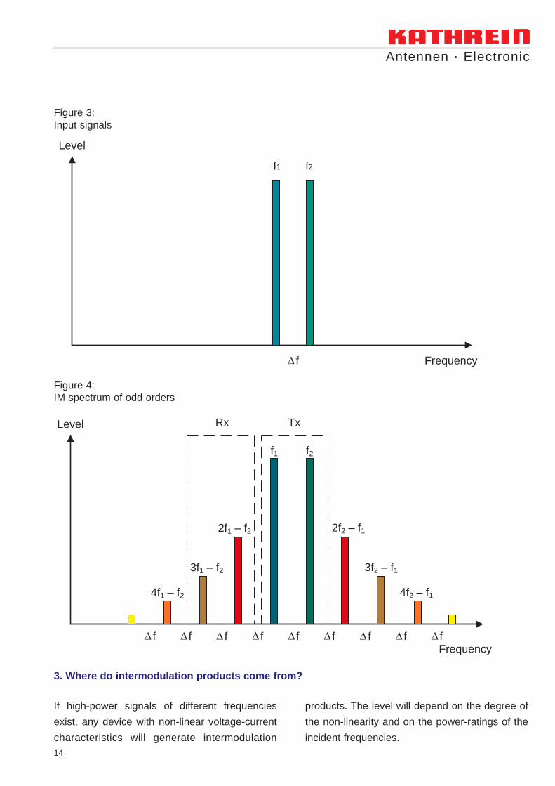
Level
Frequency
Rx Tx
f f f f f f f f f
2f2 – f1
3f2 – f1
4f2 – f1
2f1 – f2
3f1 – f2
4f1 – f2
f1 f2
Antennen · Electronic
Technical Information and New Products
Downtilting of antennasNew antennas with adjustable electrical downtiltPassive Intermodulation with Base station antennasAntennas for railway communications
Issue No. 3 - 09/2000
Contents Page
Downtilting of antennas 3 – 8
New antennas with adjustable electrical downtilt 9 – 11
Passive Intermodulation with base station antennas 12 – 17
Information about GSM-R / GPS 18 – 21
New antennas for railway applications 22 – 23
Kathrein innovations for cellular systems 24
Antennen . Electronic
“Quality leads the way”Being the oldest and largest antenna manufacturer worldwide, we take on every daythe challenge arising from our own motto. One of our basic principles is to look alwaysfor the best solution in order to satisfy our customers.Our quality assurance system conforms to DIN EN ISO 9001 and applies to the productrange of the company: Antenna systems, communication products as well as activeand passive distribution equipment.
2
Technical information in the next issue:
The influence of reflections on radiation patterns
General information about antenna installation
Network planners often have the problem that the
base station antenna provides an overcoverage.
If the overlapping area between two cells is too
large, increased switching between the base sta-
tion (handover) occurs, which strains the system.
There may even be disturbances of a neighbou-
ring cell with the same frequency.
In general, the vertical pattern of an antenna
radiates the main energy towards the horizon.
Only that part of the energy which is radiated
below the horizon can be used for the coverage
of the sector. Downtilting the antenna limits the
range by reducing the field strength in the horiz-
on and increases the radiated power in the cell
that is actually to be covered.
The simplest method of downtilting the vertical
diagram of a directional antenna is a mechanical
tipping to achieve a certain angle while using an
adjustable joint. (see Figure 1) But the required
downtilt is only valid for the main direction of the
horizontal radiation pattern. In the tilt axis direc-
tion (+/-90° from main beam) there is no downtilt
at all. Between the angles of 0° and 90° the
downtilt angle varies according to the azimuth
direction.
This results in a horizontal half-power beam
width, which gets bigger with increasing downtilt
angles. The resulting gain reduction depends on
the azimuth direction. This effect can rarely be
taken into consideration in the network planning
(see Figure 2).
Downtilting of antennas
Antennen . Electronic
1.1 Mechanical downtilt
1. Downtilting the vertical pattern
3
3 dB
10
0
90°
0°
+90
Fig. 2:Changes in the horizontal radiation pattern when various downtilt angels are used (compared to the horizon)
Fig. 1:Mechanically downtilted A-Panel
MECHANICAL DOWNTILT
0°6°8°10°
036
91215
20
Antennen . Electronic
1.2 Electrical downtilt
In general, the dipols of an antenna are fed with
the same phase via the distribution system. By
altering the phases, the main direction of the ver-
tical radiation pattern can be adjusted. Figure 3,
shows dipols that are fed from top to bottom with
a rising phase of 70°. The different phases are
achieved by using feeder cables of different
lengths for each dipole.
The electrical downtilt has the advantage, that the
adjusted downtilt angle is constant over the whole
azimuth range. The horizontal half-power beam
width remains unaltered (see Figure 4). However,
the downtilt angle is fixed and cannot be chan-
ged.
4
3 dB
10
0
-90°
0°
+90
0°6°8°10°
ELECTRICAL
Figure 4:Changes in the radiation pattern using various downtilt angles
Figure 3:Phase variations for a fixed el. downtilt
1.3 Adjustable electrical downtilt
With this technique it is possible to combine the
advantages of the mechanical downtilt (i. e.
adjustment possibility) with those of electrical
downtilt (horizontal half-power beam independent
of downtilt angle). Instead of using different fixed
cables to achieve the various phases for the dipo-
les, mechanical phase-shifters are used.
P = 1
P = 2
P = 3.5
P = 2
P = 1
Phase-shifter
+ +ϕ
+ϕ
- -ϕ
-ϕ
Figure 5:Phase diagram of an adjustable phase-shifter
ϕ = 0˚
ϕ = 70˚
ϕ = 140˚
ϕ = 210˚
ϕ = 280˚
Figure 6: Downtilt adjusting mechanism (with scale) for A-Panels
In standard applications the purpose of using a
downtilt is to limit the field strength in the horizon.
Considerable limitation is achieved if the radiated
power in the horizon is limited by 6 dB. This
means that one can easily predict the smallest
efficient tilt angle by simply tilting the vertical
radation pattern until the field strength in the hori-
zon is reduced by 6 dB.
But there is also a second important point when
calculating the optimum downtilt angle. Apart
from the main beam, vertical radiation patterns
also have two or more side lobes depending on
the number of dipoles within the antenna (see
Figure 7).
Maximum field strength reduction in the horizon is
achieved if the minimum between the main beam
and the first side-lobe is orientated towards the
horizon.
Antennen . Electronic
5
The adjustment mechanisms can be positioned
either on the rearside (Eurocell panels) or on the
bottom (F-Panels, A-Panels) of the antenna.
These phase-shifters can be used to set various
downtilt angles which remain constant over the
whole azimuth range.
2. Optimum downtilt angles
The optimum tilt angle for a particular antenna
depends on the vertical radiation pattern, especi-
ally on the half-power beam width, and therefore
also on the actual length of the antenna.
2.1 How to calculate the optimum downtilt angle
Antennen . Electronic
As the Figure 8 shows, the minimum tilt angle
that would be efficient lies at around 50° (power
in the horizon reduced by 6 dB). Using such an
angle, the antenna would beam more or less
directly into the ground. Therefore the use of a
downtilt with very small antennas (i.e. length up
to 500 mm) can not be recommended.
2.2 Small antennas – vertical half-power beam width 70°
6
Main beam
First upper side-lobe
Figure 7: Typical vertical radiation pattern
If the tilt angle is set too high, the field strength is
not reduced, but is increased again by the first
side-lobe.
Figure 8: Minimum efficient tilt angle for small antennas
10
3
0
Antennen . Electronic
The minimum efficient tilt angle for these anten-
nas (length 1.3 m) lies at 8°. At an angle of 19°
the first side-lobe lies on the horizon. This provi-
2.3 Standard antennas – vertical half-power beam width 13°
The minimum efficient tilt angle for these anten-
nas (length 2.6 m) lies at around 3°–4°. At an
angle of 8°–9° the first side-lobe lies on the hori-
zon. This provides a good range of angles for the
efficient tilting of long antennas.
2.4 Long antennas – vertical half-power beam width 6.5°
7
10
3
0
des a good range of angles for the efficient tilting
of standard antennas.
Figure 9: Minimum efficient tilt angle for standard antennas
Figure 11: Minimum efficient tilt angle for long antennas
10
3
0
10
3
0
Figure 10: First side-lobe lies on the horizon
Antennen . Electronic
For some special locations (e.g. on the tops of
high mountains, on the roof-tops of tall buildings
or for coverage in the street below etc.) a very
high downtilt angle might be necessary. To achie-
ve such high downtilt angles, a combination of
mechanically and electrically downtilted antennas
is also possible.
2.5 High downtilt angles for special locations
8
Taking all the above into account, it is easy to
imagine, how very sophisticated the development
of electrically adjustable downtilt antennas is,
since intensive measurements have to be carried
out.
All the electrical parameters must fulfil the speci-
fications with every single downtilt angle.
Electrical values such as those for side-lobe sup-
GSM and 870 – 1900 MHz741 806 Yes Dual-band antenna
GPS 1575.42 ± 1 MHz
WLL 741 747 2350 – 2550 MHz Yes
Frequency band Type No. Operating frequency range Type approved by Remarks"Deutsche Bahn AG"
22
Antennen . Electronic
• Low-profile broadband antenna in fiberglass radome.
Train Antenna2350 – 2550 MHz
Type No. 741 747
Input N femaleFrequency range 2350 – 2550 MHzVSWR < 1.5Gain 0 dB (ref. to the quarter-wave antenna)Impedance 50 ΩPolarization VerticalMax. power 100 Watt
(at 50° C ambient temperature)Weight 0.5 kgPacking size 155 x 90 x 200 mmHeight 142 mm
142
mm
• Dual-band antenna: GSM 900 and GPS.• The antenna can be operated in both frequency ranges simultaneously.• Low-profile antenna in fiberglass radome.
Train Antenna870 – 960 MHz and GPS
Type No. 741 806
GSM 900 AntennaInput N femaleFrequency range 870 – 960 MHzVSWR < 1.5Gain 0 dB (ref. to the quarter-wave antenna)Impedance 50 ΩPolarization VerticalMax. power 100 Watt (at 50° C ambient temperature)Inner conductor D.C. grounded
GPS AntennaInput Cable RG 316/U of 160 mm length
with TNC male connectorFrequency range 1575.42 ± 1 MHzVSWR < 1.5Polarization Right hand circularGain (90° elevation) 2 dB (ref. to the circularly polarized
isotropic antenna)Axial ratio 3 dBImpedance 50 ΩInner conductor D.C. grounded
Isolation ≥ 28 dB (870 – 960 MHz)≥ 20 dB (1575.42 ± 1 MHz)
Weight 0.5 kgPacking size 161 x 152 x 88 mmHeight 96 mm
96 m
m
Optional low-noise GPS pre-amplifier Type No. 742 185 will beavailable soon.