KCP&L SmartGrid Vision, Architecture, & Road Map EXECUTIVE SUMMARY The term "Smart Grid" represents a long-term vision for the electric grid that is highly automated with a tremendous amount of self-operations; distributed generation, and direct customer management of their electrical consumption. The following illustration was developed by EPRI to depict the high level of IT applications and communications integration with the grid that will be required to create the envisioned SmartGrid and create the delivery system of the future. While the "SmartGrid", in complete vision, cannot be built today, it will continue to evolve and develop over time. However, a "Smarter Grid" can be deployed within the next few years using valuable technologies that currently exist. The "Smarter Grid”, will function more efficiently and enabling us to deliver increased levels of reliability, services, and societal benefits economically in an era of rising costs. The grid that is in place at KCP&L today is substantially “smart” having benefited from decades of power engineering expertise. The systems put in place already execute a variety of sophisticated system operations and protection functions. In addition it should be noted that the foundation for what is now termed the “Smarter Grid” has been under development by the KCP&L and the industry for many years. Much of the integration has been done through incremental applications of technology, custom engineered integrations; work a rounds, and proprietary systems fitting them into system operations as well as possible. Deploying the Smarter Grid will include many incremental enhancements to the existing KCP&L electric power infrastructure. PROPOSED SMARTGRID ARCHITECTURE Architecture: The structure of components, their relationships, and the principles and guidelines governing their design and evolution over time. v 0.70 DRAFT 1
EXECUTIVE SUMMARY The term Smart Grid represents a long-term vision for the electric grid that is highly automated with a tremendous amount of self-operations distributed generation and direct customer management of their electrical consumption The following illustration was developed by EPRI to depict the high level of IT applications and communications integration with the grid that will be required to create the envisioned SmartGrid and create the delivery system of the future
While the SmartGrid in complete vision cannot be built today it will continue to evolve and develop over time However a Smarter Grid can be deployed within the next few years using valuable technologies that currently exist The Smarter Gridrdquo will function more efficiently and enabling us to deliver increased levels of reliability services and societal benefits economically in an era of rising costs
The grid that is in place at KCPampL today is substantially ldquosmartrdquo having benefited from decades of power engineering expertise The systems put in place already execute a variety of sophisticated system operations and protection functions In addition it should be noted that the foundation for what is now termed the ldquoSmarter Gridrdquo has been under development by the KCPampL and the industry for many years Much of the integration has been done through incremental applications of technology custom engineered integrations work a rounds and proprietary systems fitting them into system operations as well as possible Deploying the Smarter Grid will include many incremental enhancements to the existing KCPampL electric power infrastructure
PROPOSED SMARTGRID ARCHITECTURE Architecture The structure of components their relationships and the principles and guidelines governing their design and evolution over time
v 070 DRAFT 1
KCPampL SMARTGRID ARCHITECTURE AND ROAD MAP
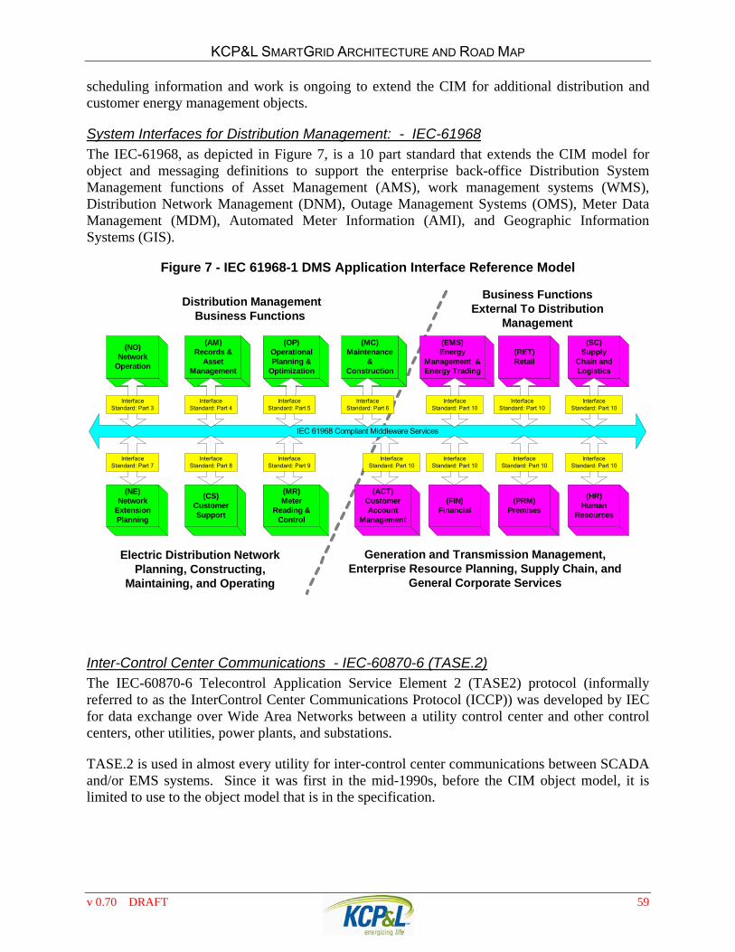
Hence an architecture is a blueprint for a solution It is important that the architecture for the ultimate fully functional SmartGrid take a high level perspective to define how the various elements are to be brought together to meet the business regulatory and technical objectives for KCPampL The perspectives of the SmartGrid Architecture must encompass all levels of operation from RTO to communications within customer premise and end-use equipment Based on the architecture system engineers create designs Designs are where technology and standards become important
In developing the proposed SmartGrid Architecture the KCPampL SmartGrid staff relied heavily on prior industry research work and use-cases developed by EPRI DOE California Energy Commission and other organizations Current industry Standards work and vendor product development plans were also used as a resource The SmartGrid Architecture will continue to be a work-in-progress and will evolve as additional applications requirements and technologies evolve Integration of PHEVs into the electric grid is an example of a future application requirement that may not be fully supported by the SmartGrid Architecture as presented
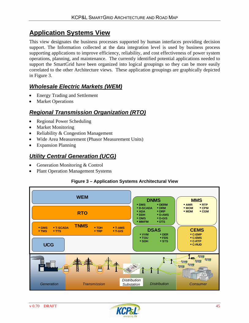
So that the proposed SmartGrid Architecture can be more clearly understood it has been presented in six (6) largely complimentary viewpoints Each viewpoint represents a different technical perspective and answers a different set of requirements These viewpoints and their most significant architectural characteristics are
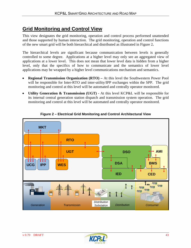
Electrical Grid Monitoring and Control ndash these functions will be both hierarchical and distributed with a high degree of automatic unattended distribution substation and field device operation To further protect against potential disruption of the bulk power system operation the architecture recommends that the distribution monitoring and control functions be implemented with a DMS and D-SCADA system separate from the existing EMS-SCADA system
Application Systems ndash This view presents the logical groupings of applications currently identified as required to implement the ultimate SmartGrid functions Many of the applications identified do not currently exist at KCPampL or are significant enhancements of the current system Prior to any implementation the application functions and requirements must be rigorously defined through a use-case development process
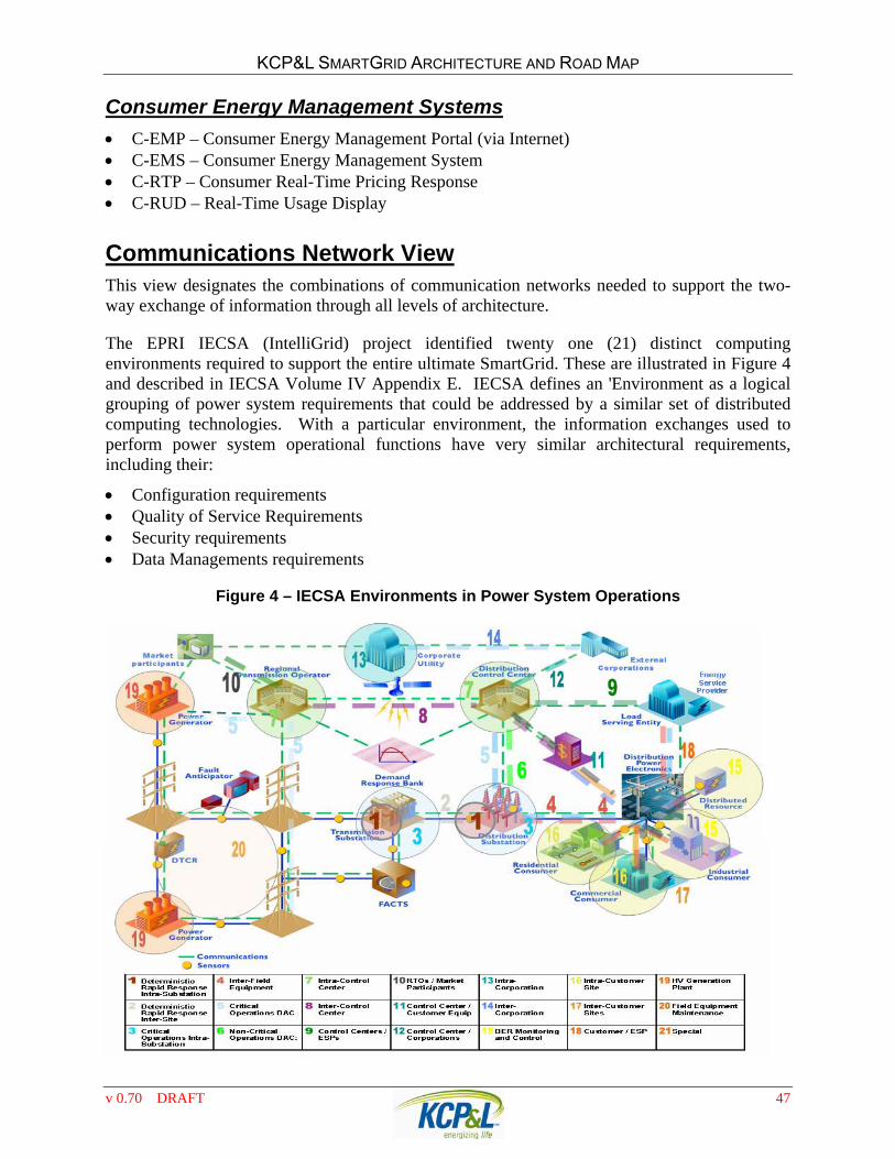
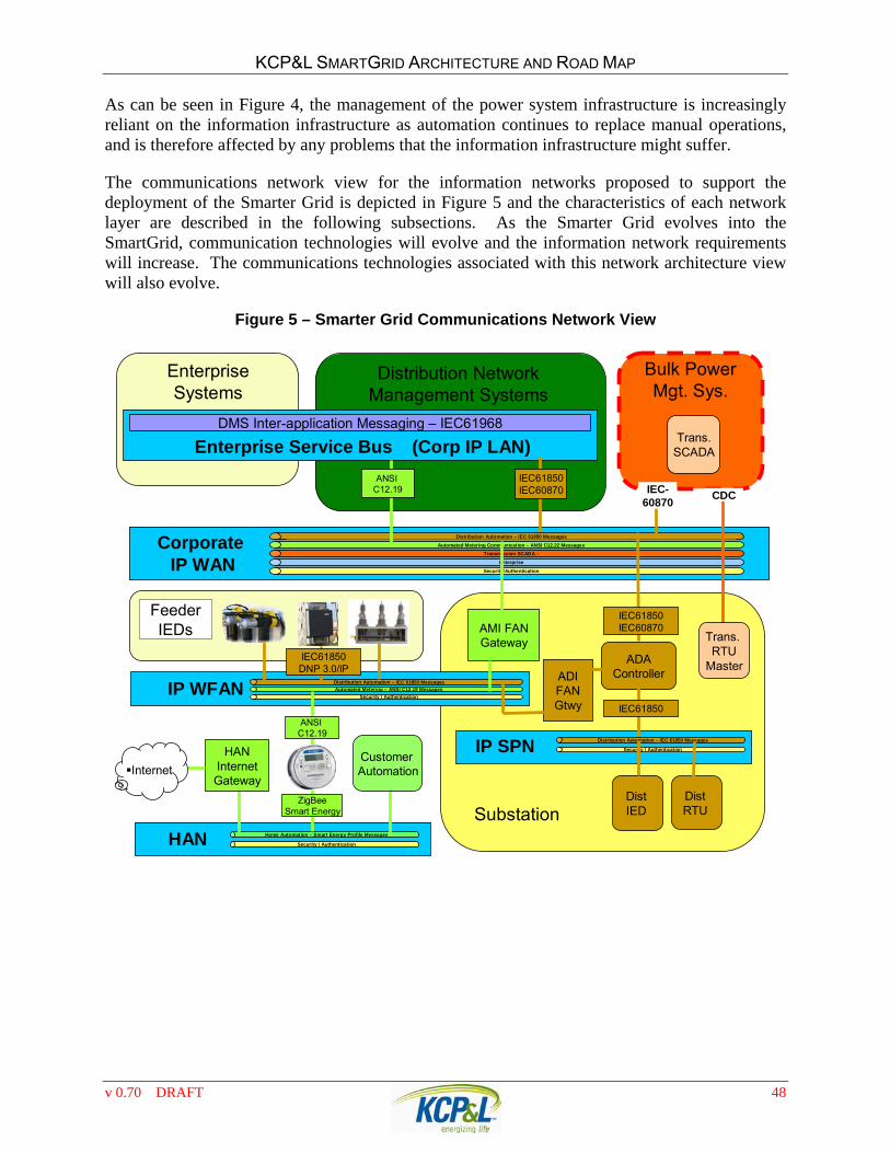
Communications Network ndash This view presents the communication architecture to support the SmartGrid It includes 1) the expansion of the KCPampL IT IP WAN to all substations to provide the backhaul communications required for the grid automation and AMI 2) the deployment of an IP SPN (Substation Process Network) to provide the communication requirements for distribution substation automation 3) the deployment of a private mesh radio WFAN (Wireless Field Area Network) to provide the field communications required for grid automation and AMI and 4) a ZigBee communication module in the AMI meters to communicate with WHANs (Wireless Home Area Network) and ldquosmartrdquo appliances
Data Integration amp Interoperability ndash This view presents the information technologies needed to store and move the data through the communication infrastructure layers from device to device device to application and between applications The National Institute of Standards and Technologies (NIST) has been mandated to drive SmartGrid interoperability Standards to a consensus so that they can be implemented by rule by FERC and other oversight bodies
v 070 DRAFT 2
KCPampL SMARTGRID ARCHITECTURE AND ROAD MAP
With the work completed to date by NIST and EPRI it appears that the following standards will be required key components of this architecture view 1) IEC-61970 defines a Common Information Model (CIM) and a Generic Interface Definition (GID) for utility systems 2) IEC-61968 defines the SmartGrid back-office application-to-application integration and incorporates a Service Oriented Architecture (SOA) built on top of an Enterprise Integration Bus (EIB) 3) IEC-60870 defines the control center to control center messaging 4) IEC-61850 will become the communication standard for substation automation and will be expanded to include feeder device automation DNP 30IP will provide a transition path for field devices
The AMI and HAN integration standardization remains very polarized and will take longer for a standards path to materialize Interoperability between systems is a critical issue at this level for applications to leverage the data collected and extract maximum value
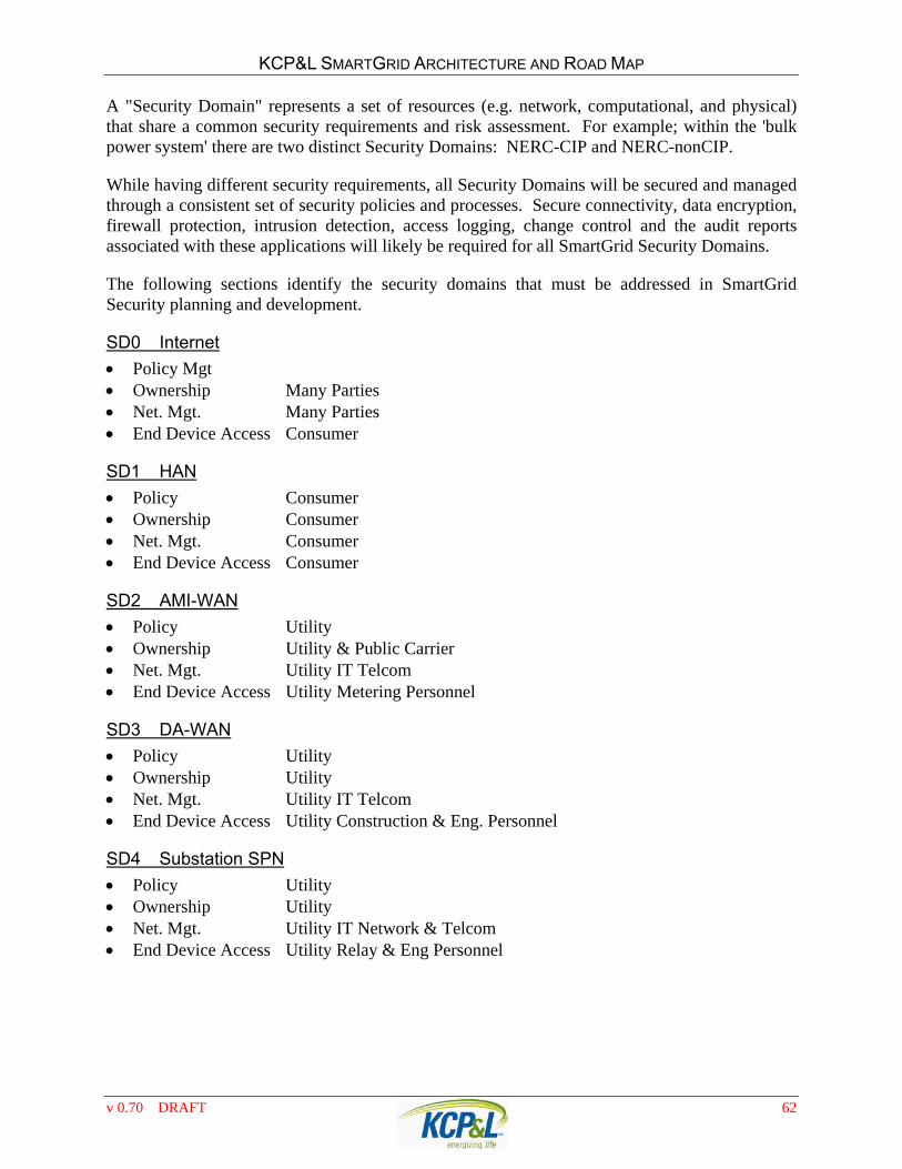
Security ndash This view presents the security requirements and technologies envisioned to secure the SmartGrid NERC-CIP compliance is mandated for the bulk power system The hierarchical nature of the technologies presented in the Communications and Grid Monitoring and Control Architecture views provides for the security ldquocheck-pointsrdquo between control layers that may have different security requirements Secure connectivity data encryption firewall protection intrusion detection access logging change control and the audit reports associated with these applications will likely be required for all SmartGrid communications To enhance the ability to properly secure the SmartGrid infrastructure it is recommended that 1) KCPampL utilize private communications (wired and wireless) infrastructure to provide all Grid Operations communications 2) Public wireless communications may be incorporated to provide additional AMI only back-haul and a D-SCADA system should be installed to support the DMS and all distribution control functions Separating the T amp D SCADA functions will provide enhanced security for the bulk-power electric grid
Regulatory ndash This view presents the regulatory influences and requirements that can become key to any successful SmartGrid deployment The regulatory aspects of SmartGrid are complicated by the fact that FERC has jurisdictional authority of the transmissionwholesale grid and MO-PSC and the KS-ICC have jurisdictional authority over the operation of the delivery grid in their respective states
Both state commissions are currently considering three (3) new PURPA requirements that related directly to the SmartGrid 1) Rate Redesign to promote energy efficiency 2) SmartGrid Investment and 3) SmartGrid Information KCPampL has recommended that the commissions use a collaborative workshop process to develop the framework for considering these issues The IL commission mandated that Ameren and Comm Edison participate in a formal state-wide SmartGrid Road Map
Successful collaboration with the Commissions Legislatures and Consumer Organizations on transitional issues will be key to achieving the level of consumer acceptance participation and enthusiasm in the new energy management concepts needed to make the SmartGrid deployment a success Inverted Block rate structures will be needed to promote energy efficiency and effective Time of Use rates will be needed to promote shifting energy consumption off-peak The new standard AMI meters are designed to easily support TOU
v 070 DRAFT 3
KCPampL SMARTGRID ARCHITECTURE AND ROAD MAP
rates with 4-daily usage times and 4-seasonal periods allowing for very flexible rate implementations
PROPOSED SMARTGRID ROAD MAP The SmartGrid in complete vision cannot be built today but will instead develop over time Most utilities have a similar vision for an ultimate SmartGrid but will take different paths and time-lines in their respective SmartGrid deployments These paths will be influenced by regulatory and business drivers and the mix of technologies that a company has currently installed The SmartGrid Road Map presented here is a plan for implementing the vision and functionality of KCPampLs SmartGrid over time
Strategic Drivers The Sustainable Resource Strategy component of the GPE Strategic Intent Deliverys Strategic Focus on Cost Performance and Customer Satisfaction
Short-Term Business Drivers Economy downturn rate case slippage and the budget constraints through 2010 Federal SmartGrid grants through the ARRA Stimulus package Elevate GMO distribution monitoring and control to KCPampL levels to improve reliability
and operational costs Implement AMI in GMO to reduce operational costs and provide GMO customers access to
same level of information available to KCPampL customers KCPampL AMR contract with CellNet expires Aug 2014 Expand of EE and DR programs to GMO customers Provide the Net-metering support for solar and other renewable forms of generation to meet
the MO Prop-C renewable energy mandate Leverage existing and planned budget dollars to fund SmartGrid deployments where
possible
v 070 DRAFT 4
KCPampL SMARTGRID ARCHITECTURE AND ROAD MAP
DEVELOPING THE ROAD MAP In developing this SmartGrid Roadmap the SmartGrid staff studied several SmartGrid pilot projects and their respective road map documents Many of these are focused on AMI and selling SmartGrid as a means of empowering consumers to lower their usage and correspondingly their utility bills While this may ultimately be the case with KCPampLrsquos historically low rates we do not believe our customer are ready to embrace these load shifting initiatives on a large scale KCPampLrsquos customers continue to be more focused on reliability and quality of service issues
Our approach The benefits of the SmartGrid are obvious and the costs to implement it will be considerable It is important that we lsquoget it rightrsquo and maximize the benefits we obtain as we make the grid smarter and add functions and capabilities From a regulatory perspective it is also important that the costs associated with the technology rollout be borne by those consumers who receive the benefits In our analysis we have concluded that we should not focus immediately on the end-user interactions rather we should begin on the operational side first If we focus on the distribution grid operations and AMI we can streamline operations thus reducing costs and gain more control of the grid thus increasing reliability
Road Map Principles Support the strategic and short-term business drivers
There is no SmartGrid silver bullet technology SmartGrid projects should implement technology that comply with the defined architecture and provide the greatest operational benefits
Leverage the Federal Smart Grid demonstration project and investment grant funding authorized by the Energy Independence and Security Act of 2007 (EISA)
10 year time-line to deploy existing and emerging SmartGrid technologies
By 2020 the SmartGrid infrastructure should be able to support advanced grid technologies and potential customer programs deployed across the grid
Initial priority should be on projects that that deploy SmartGrid enabling technologies and leverage existing AMR and DA competencies AMI is considered an enabling technology There are immediate utility operation benefits from the AMR functions and the 2-way communications enables additional utility operational benefits
Consumer facing programs should be preceded with a consumer education program and a well structured pilot of the technology to evaluate consumer enthusiasm Numerous consumer facing programs will need to be implemented but KCPampL should focus on the ones that are of interest to the largest segment of the consumers There are only so many programs that can be effectively managed
The Road Map should be reviewed periodically as business drivers change revisions made to the Architecture or new capabilities or opportunities emerge in the industry
v 070 DRAFT 5
KCPampL SMARTGRID ARCHITECTURE AND ROAD MAP
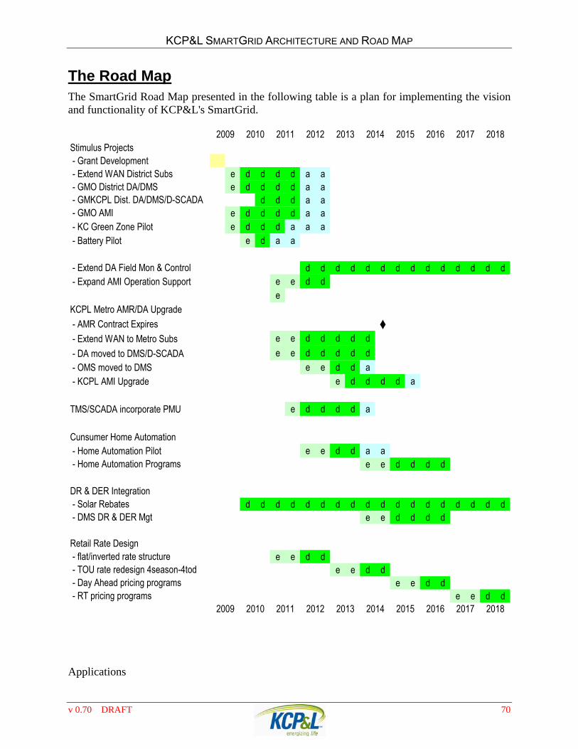
The Road Map The SmartGrid Road Map presented in the following table is a plan for implementing the vision and functionality of KCPampLs SmartGrid
Stimulus Projects - Grant Development - Extend WAN District Subs e d d d d a a - GMO District DADMS e d d d d a a - GMKCPL Dist DADMSD-SCADA d d d a a - GMO AMI e d d d d a a - KC Green Zone Pilot e d d d a a a - Battery Pilot e d a a
- Extend DA Field Mon amp Control d d d d d d d d d d d d d d - Expand AMI Operation Support e e d d
eKCPL Metro AMRDA Upgrade
- AMR Contract Expires diams - Extend WAN to Metro Subs e e d d d d d
- DA moved to DMSD-SCADA e e d d d d d
- OMS moved to DMS e e d d a - KCPL AMI Upgrade e d d d d a
TMSSCADA incorporate PMU e d d d d a
Cunsumer Home Automation - Home Automation Pilot e e d d a a - Home Automation Programs e e d d d d
DR amp DER Integration - Solar Rebates d d d d d d d d d d d d d d d d d d - DMS DR amp DER Mgt e e d d d d
Retail Rate Design - flatinverted rate structure e e d d - TOU rate redesign 4season-4tod e e d d - Day Ahead pricing programs e e d d - RT pricing programs e e d d
2016 2017 20182009 2010 2011 2012 2013 2014 2015
2009 2010 2011 2012 2017 20182013 2014 2015 2016
v 070 DRAFT 6
KCPampL SMARTGRID ARCHITECTURE AND ROAD MAP
SMARTGRID BACKGROUND
WHY A SMART GRID The early roots of current SmartGrid initiatives originate with the Arab Oil Embargo of 1773-74 The formation of the Department of Energy (DOE) was in response to oil embargo The DOE promoted energy conservation and thus less reliance on foreign oil by increasing automobile mpg ratings increasing energy efficiency of buildings and increasing appliance efficiencies through the ENERGY STARreg program As oil supplies stabilized and low gas prices returned there was less public focus on these needs
The next SmartGrid milestone occurred with the New York City Blackout in 1977 While this incident was initiated by natural causes and was isolated to New York City it focused attention on electrical system and the need for a stable power grid
The Northeast Blackout of 2003 because the defining incident that launched a multitude of Smart Grid studies and initiatives The wide spread nature of the blackout and the fact that it was avoidable or could have been significantly minimized with correct operations illustrated the need to significantly invest in the modernization of the electric supply grid
WHAT IS THE SMART GRID As a result of the Northeast Blackout DOE launched a the Modern Grid Initiative which resulted in a report entitled A Vision for the Modern Grid the European Commission commissioned a similar sturdy which produced the European SmartGrids Technology Platform the Galvin Electric Initiative introduced micro-grids and the concept of PerfectPower and EPRI developed their IntelliGrid Architecture Framework for modernizing the grid by integrating computing technology with the traditional electric grid These and many other efforts contributed to developing a vision and the requirements of a future modern electric grid
The grid modernization studies previously noted have lots of commonality but have slightly different emphasis and thus each provided its own answer to what is a Smart Grid Congress solved this definitional problem with the Statement of Policy on Modernization of Electricity Grid provided the following policy statement which defines the characteristics of a Smart Grid
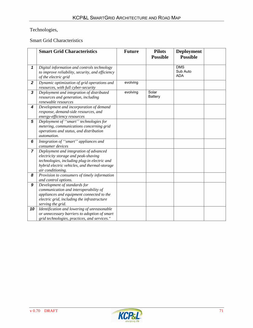
It is the policy of the United States to support the modernization of the Nationrsquos electricity transmission and distribution system to maintain a reliable and secure electricity infrastructure that can meet future demand growth and to achieve each of the following which together characterize a Smart Grid
1 Increased use of digital information and controls technology to improve reliability security and efficiency of the electric grid
2 Dynamic optimization of grid operations and resources with full cyber-security
3 Deployment and integration of distributed resources and generation including renewable resources
4 Development and incorporation of demand response demand-side resources and energy-efficiency resources
5 Deployment of lsquolsquosmartrsquorsquo technologies (real-time automated interactive technologies that optimize the physical operation of appliances and consumer devices) for metering communications concerning grid operations and status and distribution automation
v 070 DRAFT 7
KCPampL SMARTGRID ARCHITECTURE AND ROAD MAP
6 Integration of lsquolsquosmartrsquorsquo appliances and consumer devices
7 Deployment and integration of advanced electricity storage and peak-shaving technologies including plug-in electric and hybrid electric vehicles and thermal-storage air conditioning
8 Provision to consumers of timely information and control options
9 Development of standards for communication and interoperability of appliances and equipment connected to the electric grid including the infrastructure serving the grid
10 Identification and lowering of unreasonable or unnecessary barriers to adoption of smart grid technologies practices and services
The metering industry places great emphasis on AMI and Smart Meters From many of the trade journal articles one would get the impression that Smart Grid = AMI Note that of the ten Smart Grid characteristics AMI and Smart Meters is only a portion of one characteristic Congress chose to include the entire electric grid in its definition from generation to consumption all components should be smart efficient optimized and reliable
Later in EISA 2007 Section 1306 (d) the term smart grid functions is defined to mean any of the following
1 The ability to develop store send and receive digital information concerning electricity use costs prices time of use nature of use storage or other information relevant to device grid or utility operations to or from or by means of the electric utility system through one or a combination of devices and technologies
2 The ability to develop store send and receive digital information concerning electricity use costs prices time of use nature of use storage or other information relevant to device grid or utility operations to or from a computer or other control device
3 The ability to measure or monitor electricity use as a function of time of day power quality characteristics such as voltage level current cycles per second or source or type of generation and to store synthesize or report that information by digital means
4 The ability to sense and localize disruptions or changes in power flows on the grid and communicate such information instantaneously and automatically for purposes of enabling automatic protective responses to sustain reliability and security of grid operations
5 The ability to detect prevent communicate with regard to respond to or recover from system security threats including cyber-security threats and terrorism using digital information media and devices
6 The ability of any appliance or machine to respond to such signals measurements or communications automatically or in a manner programmed by its owner or operator without independent human intervention
7 The ability to use digital information to operate functionalities on the electric utility grid that were previously electro-mechanical or manual
8 The ability to use digital controls to manage and modify electricity demand enable congestion management assist in voltage control provide operating reserves and provide frequency regulation
9 Such other functions as the (DOE) Secretary may identify as being necessary or useful to the operation of a Smart Grid
v 070 DRAFT 8
KCPampL SMARTGRID ARCHITECTURE AND ROAD MAP
PRIOR WORK LEVERAGED IN DEVELOPING THIS VISION In developing the proposed SmartGrid Architecture and Road Map the KCPampL SmartGrid staff relied heavily on prior KCPampL studies industry research work and use-cases developed by EPRI DOE California Energy Commission and other organizations Prior works used in developing the SmartGrid Architecture as presented include
In 1994 a KCPampL project team issued an internal company report Distribution Automation ndash A Strategic Initiative
In 1994 the previous internal report was expanded upon in a masters thesis entitled Distribution Automation at KCPampL authored by Duane Anstaett
In 2001 EPRI launched the Consortium for an Electric Infrastructure to support a Digital Society (CEIDS) with the objective of conducting RDampD that would lay the foundation for the power delivery infrastructure of the future CEIDS established a vision of the power delivery system of the future as being a smart grid that incorporates information and communications technologies into every aspect of electric delivery from ndash from generation to consumption ndash and created a technology development roadmap
In 2003 CEIDS contracted with GE to develop an industry-wide architecture for the communication networks and intelligent devices that would form the basis of the smart grid The IntelliGrid Architecture was released in 2005 and has now been used by several utilities
In 2004 CEIDS contracted with ABB to develop a distributed computing architecture that would be able to effectively convert the tremendous amount of data that would be generated by the smart grid into information that can be acted upon
In 2004 CEIDS began defining the requirements for a consumer portal that would serve as the communications link between electric utilities and consumers
In 2004 EPRI issued a report Technical and System Requirements for Advanced Distribution Automation
In 2007 the IntelliGrid Architecture Methodology was published by the IEC as a Publically Available Specifications
In 2006 CEIDS changed its name to IntelliGrid The IntelliGrid program continues today to conduct research development and demonstrations that refines the smart grid vision and builds towards an industry architecture that promotes interoperable systems
In 2008 The GridWise Architecture Council issued a report entitled GridWise Interoperability Context-Setting Framework with the intent to provide the context for identifying and debating interoperability issues and to make drive to consensus on issues to make the integration of complex SmartGrid systems easier
In 2007 EPRI issued a report Value of Distribution Automation Applications prepared for the California Energy Commission under the Public Interest Energy Research Program
v 070 DRAFT 9
KCPampL SMARTGRID ARCHITECTURE AND ROAD MAP
In 2008 EPRI issued a report Integrating New and Emerging Technologies into the California Smart Grid Infrastructure prepared for the California Energy Commission under the Public Interest Energy Research Program
Current industry Standards work and vendor product development plans were also used as a resource The SmartGrid Architecture will continue to be a work-in-progress and will evolve as additional applications requirements and technologies evolve Integration of PHEVs into the electric grid is an example of a future application requirement that may not be fully supported by the SmartGrid Architecture as presented
KCPampLS DISTRIBUTION AUTOMATION HISTORY KCPampL has a long history of being a progressive industry leader in the area of distribution automation These long standing efforts are evident in KCPampLs tier-1 standing in reliability performance when KCPampL was named the most reliable electric utility nationwide and awarded the 2007 ReliabilityOnetradeNational Reliability Excellence Award by the PA Consulting Group
THE EARLY YEARS In the early 1980s KCPampL implemented a new centralized EMSSCADA system to monitor and control the transmission system Through the 1980s this system was expanded to include the monitor and control distribution substations and the distribution the distribution feeder breaker By the early 1990s all of the distribution substations in the Kansas City metropolitan service area were monitored and controlled by a centralized distribution dispatch department using the EMS
DA - A 1993-1999 STRATEGIC INITIATIVE In 1993 Kansas City Power amp Light Company (KCPampL) management established an internal interdivisional multi-disciplined team to develop definitions economic evaluations recommendation plans for Distribution Automation at KCPampL The teams purpose was to determine the feasibility of consolidating numerous existing but independent automation efforts that were undergoing evaluation throughout the company Perception was that most of the automation efforts required eventual integration Consequently KCPampL management consolidated the DA efforts into one project under the direction of a DA project leader and team
The following subsections contain excerpts from the Distribution Automation Teams report and recommendations to management
v 070 DRAFT 10
KCPampL SMARTGRID ARCHITECTURE AND ROAD MAP
Excerpts from the Distribution Automation Study Kansas City Power amp Light Company has an opportunity to establish a stronger position in the reregulated and competitive arena in which we must conduct business Coupled with the many changes happening in the electric utility business are even more changes taking place in the telecommunications and information technology markets Due to deregulation of the telecommunications industry several years ago many technologies have developed and matured that electric utility companies can economically justify plus provide opportunities to strategically leverage their use to improve customer services control rising costs and provide additional services
All of KCPampLs customers are connected via our electric distribution system It is reasonable to assume that we will remain in the electric distribution and retail sales for the foreseeable future Since we serve customers directly through this portion of our system it appears that cost effective improvements in distribution operations and customer service is imperative With the convergence of todays telecommunications and information technologies it appears that automating the distribution system is a practical endeavor
Distribution Automation Functional Subsystems
The DA Project Teams first order of business was to identify what functional IT and control subsystems would be considered a part of Distribution Automation Following is a brief description of each area that was identified as part of distribution automation and therefore considered for inclusion in the DA Project
AMR - Automated Meter Reading Provides the ability to replace existing manual meter reading processes with an automated process Functionality developed as part of AMR significantly impacts the effectiveness of future DSM programs
ACDVRU ndash Automatic Call Director with Voice Response Unit Primarily provides improved call handling capability for the Call Center and will provide a direct transfer of Outage Calls to the OMS system
DFMS-AMFMGIS ndash Automated MappingFacilities ManagementGeographic Information System Provides the functionality to support the design mapping record keeping and maintenance of the electrical system via a fully connected and geographically related model
DFMS-WMS ndash Work Management System Provides for automated job planning and management of resources
DFMS-EAS ndash Engineering Analysis System Provides the functionality for analysis of the distribution systems electrical performance and plans for the necessary construction and maintenance of the system
DFMS-TRS Trouble Reporting System Provides functionality to support the day-to-day trouble call tracking outage analysis and service restoration of the electrical distribution system
v 070 DRAFT 11
KCPampL SMARTGRID ARCHITECTURE AND ROAD MAP
DFMS-D3MS ndash Dynamic Distribution Data Management System Primarily provides the interface between the DFMS functional component applications and various remote distribution automation RTUs demand side management devices and automated meter reading devices This subsystem will maintain a data repository of distribution data about the status of remotely monitored points that are dynamic in nature as well as provide the interface between the DFMS application components the EMS and the various DA communications networks During the solicitation of proposals it was determined that there was no commercially available product available to provide this functionality
DFMS-LDA - Line Device Automation This includes but is not limited to automated operation and control of capacitors switches reclosers regulators and monitoring equipment
DSM - Demand Side Management The purpose of DSM is to avoid capital outlays through the influence and control of the customers electric energy use Energy use is affected by the customers quantity and timing requirements
The KCPampL Distribution Automation Vision
The vision for distribution automation consists of using a combination of computer hardware and software telecommunications networks and electronic devices to provide the following
1 Monitor and control from a central location critical electrical devices such as capacitor banks voltage regulators switches and reclosers This automated control and monitoring of such devices will improve outage response and restoration plus achieve efficiencies in the distribution system to minimize losses saving generating capacity and fuel costs
2 From a central location send and monitor curtailment requests to commercial and industrial customers equipment Both KCPL and the customer can monitor usage to verify compliance
3 Automatically read meters and have on-line access to demand time-of-use and load profile data Connectdisconnect functions will be performed from a central location as well as provide tamper detection bill consolidation and anytime reading of meters Customers may receive their bill any day of the month they choose
4 Smart homes and customer devices can be connected to be alerted to peak conditions special pricing or other information from the utility
5 This technology will interface with KCPampLs current computer network and Customer Information System as well as voice response units When a customer has a problem they call KCPL the Caller ill is forwarded ahead of the telephone call and the system picks up the caller ill When the system answers the call the customer is greeted by name and told that we are aware of hisher problem and that a crew has been dispatched and what time they will arrive When the problem is corrected the crew can notify the system of the correction and the system will call the customer back along with automatically checking to see if the power is actually on by checking the meter
6 This system can be expanded to read gas and water meters along with providing many other services such as security alarm services as well as many others providing opportunities to expand our revenue stream
v 070 DRAFT 12
KCPampL SMARTGRID ARCHITECTURE AND ROAD MAP
The Business View
We believe that implementation of this technology will enable KCPL to transform the way we do business and interact with customers This technology will maximize the margins in our core business plus provide opportunities outside the companys traditional markets Automating key distribution processes establishing an electronic interface with the customer and creating the opportunity to expand our services places KCPL in a stronger competitive position for the future As an expanded services provider KCPL leverages the competencies and assets of an energy services supplier The telecommunications infrastructure provides a wide variety of business opportunities Home and business automation is viewed as a logical extension of our energy services
Improved Customer Service
Real-time Pricing Flexible Billing schedule Consolidated Billing Offers customers a choice Adds services for customers
Improved Revenue
Pricing incentives to reduce peak load Pricing incentives to increase off-peak load Increase annual revenues
Const Control through Technology
Reduce Manpower Faster Restoration Better Load control More efficient utilization of Distribution System
Once this system is in place KCPL will be strategically positioned for the competitive marketplace and can take advantage of many opportunities Those opportunities include retail wheeling improved crisis management on the distribution system improved responsiveness to customers and improved energy services
DA Implementation In late 1994 realizing the strategic nature of the DA initiative in preparing KCPampL for potential deregulation of the electric markets the pending Y2K issues and impact on operational and reliability the KCPampL management approved the majority of the DA recommendations and authorized to major multi-year projects to implement AMR and DFMS
v 070 DRAFT 13
KCPampL SMARTGRID ARCHITECTURE AND ROAD MAP
Systems Implemented
Between 1995 and 1999 KCPampL implemented the following components of the DA vision
AMR KCPampL implemented the first utility wide 1-way AMR system in the industry automating over 90 of all customer meters
ACDVRU Provides improved call handling capability for the Call Center and will provide a direct transfer of Outage Calls to the Outage Management System (OMS)
DFMS-AMFMGIS KCPampL entered into data sharing agreements with 7 city and county entities to obtain the most accurate land base information available on which its hard copy facility maps were digitized
DFMS-WMS Provides for automated job planning and management of resources
DFMS-EAS
DFMS-TRS This system is now referred to as the OMS Outage Management System
DFMS-LDA Device Automation was limited to Capacitor Automation Over 600 line capacitors have been automated and routinely maintain the urban circuits at nearly unity power factor
Systems Not Implemented
Based on further detailed analysis several of the components of the 1993 DA Vision were not implemented for a variety of reasons
DFMS-D3MS ndash During our vendor selection process the vendor products in this area were found to be lacking the desired functionality Due to the risk associated with the lack of functionality KCPampL decided to hold off implementing this system and related line device automation 15 years later vendors are now providing the desired functionality in solutions referred to as DMS or Distribution Management Systems
DFMS-LDA - Line Device Automation Due to the lack of a D3MS the automation of switches reclosers regulators and other monitoring equipment was deferred
DSM - Demand Side Management During a more detailed review it was concluded that the communication and control technology to pursue DSM on a large scale lacked sufficient maturity The greatest potential was found to be in the area of large commercial and industrial customers not small commercial or residential Further consideration of DSM was deferred to later consideration as independent business cases and rate tariffs would have to be filed for these
v 070 DRAFT 14
KCPampL SMARTGRID ARCHITECTURE AND ROAD MAP
LEVERAGING THE DA INVESTMENT ndash 2000-2006 AND FURTHER INTEGRATING THE SUBSYSTEMS Having successfully implemented the systems initiated by the DA Initiative KCPampL identified cost justified and implemented a series of projects that leveraged the system implementations establishing greater process integration operational savings and improved operational performance for customers Many of these projects included first of its kind technology deployments within the utility industry
AMFMGIS Upgrade KCPampL became the first utility to port our vendors AMFMGIS system from their production legacy CAD-RDBMS platform to a fully RDBMS platform
AMFMGIS to WMS Integration - Integration automated the population of GIS attributes based on the WMS compatible units This functionality established the foundation for an eventual integrated graphic design function
WMS Expanded to Maintenance Work - Use of the WMS was expanded from design-construction jobs to high volume maintenance and construction service orders automating and streamlining those processes
Account Link WEB portal integrated AMR and CIS ndash The AccountLink customer web portal was established and daily AMR read information was made available to customers
AMR integrated with OMS AMR outage (last gasp) alerts and AMR meter lsquopingsrsquo were implemented to improve outage and trouble response
ORS dashboard integrated with OMS - Implemented the Outage Records System an OMS data mining and management dashboard provides real time summary and overview of outage statistics This system provides the real-time ldquoOutage Watchrdquo map on the KCPampL web page wwwkcplcom
MWFM Integrated with AMFMGIS OMS and CIS - Implemented the Mobile Work Force Management system which automated the field processing of Trouble Outage and CIS Meter Service Orders
v 070 DRAFT 15
KCPampL SMARTGRID ARCHITECTURE AND ROAD MAP
THE COMPREHENSIVE ENERGY PLAN ndash 2004-2009 In 2004 GPE and KCPampL undertook a comprehensive strategic planning process The result was a unique and innovative partnership in full collaboration with its stakeholders that became the GPEKCPampL Strategic Intent ndash a substantive achievable plan that serves as the companyrsquos roadmap in guiding growth and demonstrating leadership in supplying and delivering electricity and energy solutions to meet customersrsquo needs now and far into the future The companyrsquos approach has received national attention In January 2007 an article in Barronrsquos praised GPErsquos efforts stating ldquo[T]he kind of strategy it has pursued will be necessary for any utility to succeed in the coming yearsrdquo
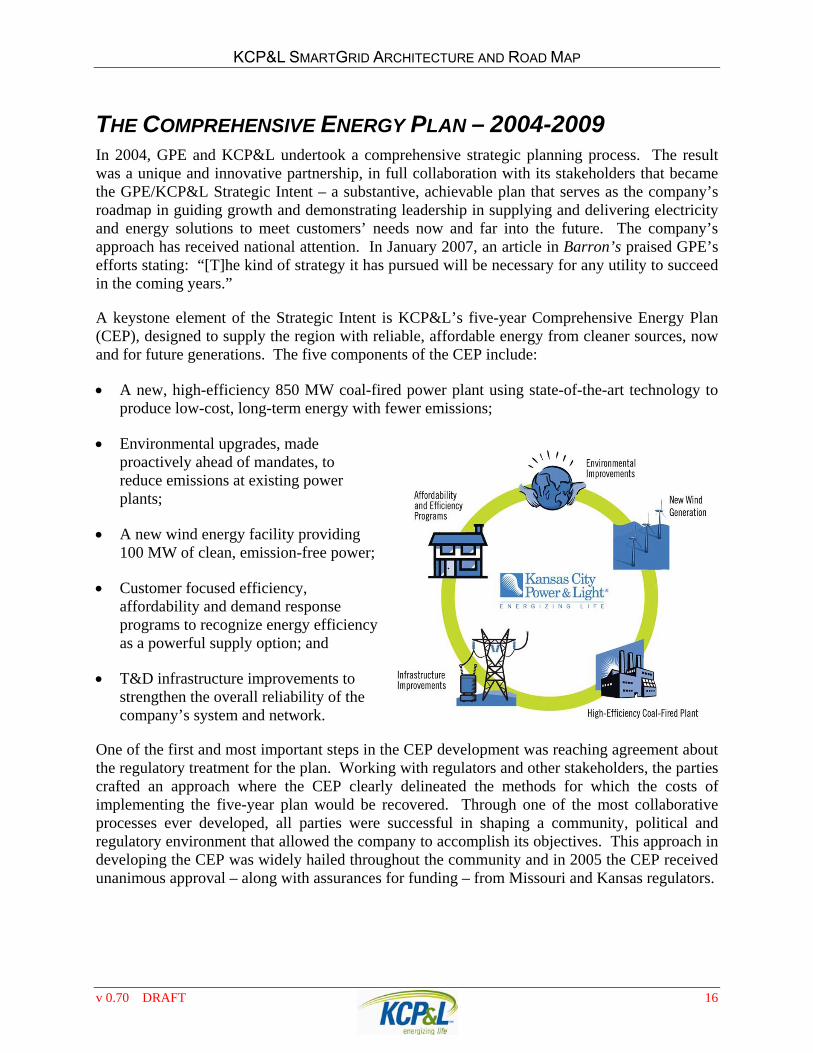
A keystone element of the Strategic Intent is KCPampLrsquos five-year Comprehensive Energy Plan (CEP) designed to supply the region with reliable affordable energy from cleaner sources now and for future generations The five components of the CEP include
A new high-efficiency 850 MW coal-fired power plant using state-of-the-art technology to produce low-cost long-term energy with fewer emissions
Environmental upgrades made proactively ahead of mandates to reduce emissions at existing power plants
A new wind energy facility providing 100 MW of clean emission-free power
Customer focused efficiency affordability and demand response programs to recognize energy efficiency as a powerful supply option and
TampD infrastructure improvements to strengthen the overall reliability of the companyrsquos system and network
One of the first and most important steps in the CEP development was reaching agreement about the regulatory treatment for the plan Working with regulators and other stakeholders the parties crafted an approach where the CEP clearly delineated the methods for which the costs of implementing the five-year plan would be recovered Through one of the most collaborative processes ever developed all parties were successful in shaping a community political and regulatory environment that allowed the company to accomplish its objectives This approach in developing the CEP was widely hailed throughout the community and in 2005 the CEP received unanimous approval ndash along with assurances for funding ndash from Missouri and Kansas regulators
v 070 DRAFT 16
KCPampL SMARTGRID ARCHITECTURE AND ROAD MAP
TampD Infrastructure Improvement Programs KCPampL currently operates one of the most reliable networks in the country meaning that the risk of outages for our customers is much lower than for customers in other cities We want to keep it that way One element of the CEP involved infrastructure improvements to strengthen the overall reliability of our system and network Our plan
included constructing replacing andor upgrading existing transmission and distribution facilities to accommodate new generation and incorporate new technologies for faster diagnosis and repair of service interruptions
Asset Management at KCPampL is the structured and disciplined process to develop the program of work for system expansion system improvements and maintenance both corrective and preventive Our objective is to provide a program of work to achieve the following three key corporate strategic goals for the least overall cost
Distribution System Inventory Verification Program 2007-2009
This program involves conducting a full overhead distribution system field inventory to verify and augment existing distribution asset information at the component level Based on the inventory data the Asset Management and Engineering group will conduct targeted asset management and reliability studies focused on reducing outage minutes caused by problem or failure prone equipment wildlife lightning overhead wire issues and inadequate line design and construction Benefits resulting from the studies and resulting system improvements include improved reliability and customer satisfaction due to reduced outages
KCPampL conducted a pilot inventory program in 2005 and based on the pilot changes were made to increase the emphasis on network connectivity customer location verification and improved transactional processing of field collected updates The field portion of the program for KCPampL was completed on an 18 month schedule This included the collection of GPS coordinates for all facility locations verifying all assets and grid connectivity from substation to customer and verification of customer service locations
Distribution Automation Programs In 2006 KCPampL began implementation of the DA programs that were funded under CEP The objective of the Distribution Automation projects is to improve customer service reliability and worker safety by taking advantage of technological innovation KCPampL has successfully been utilizing automation in Transmission amp Distribution applications and has received recognition and awards for its innovative automation technology implementation
Network Automation 2007-2008
The Network Automation Project involves monitoring of KCPampLrsquos underground (UG) network Prior to this project KCPampL had no means to monitor the activity of this network During annual inspections network protectors were found that had excessive operations and some were in a state of disrepair and had to be replaced Automation of the network alerts engineers dispatchers and the underground workers to abnormal situations that can potentially cascade into larger problems if left unchecked The project has resulted in a better understanding of the root causes of problems and then proactively managing the network premature failures have already
v 070 DRAFT 17
KCPampL SMARTGRID ARCHITECTURE AND ROAD MAP
been averted and it is anticipated that the lives of transformers and network protectors will be extended all resulting in deferral of replacement of such expensive equipment
50 CO Automation 2008-2009
The 50 CO Automation Project involves remote enabling or disabling of over-current relays (50 CO) installed at substations 50 CO relays are designed to trip open before lateral fuses blow thereby preventing sustained outages The ability to turn the relays off under fair weather conditions will result in a forty to fifty percent reduction in momentary outagesndashgreatly improving reliability and customer quality-of-service When turned on during storms this system will allow reclosing to save fuses and reduce outages
Dynamic Voltage Control (DVC) 2007-2008
As a result of successful testing of the DVC system on the Integrated Circuit of the Future KCPampL accelerated implementation of the DVC system to all 203 metro Kansas City substation buses resulting in an estimated 60MW of peak demand reduction
34-kV Switching Device Automation and Fault Indication 2006-2009
The 34-kV Switching Device Automation and Fault Indication Project involves installation of automated switching devices and fault indicators The rural circuits in the East and South Districts on KCPampLrsquos 34-kV system are quite lengthy and therefore when there is an outage locating the cause of the outage can be time-consuming resulting in longer duration outages Also because the 34-kV feeders serve various 12-kV substations and municipalities the number of customers affected is significant In addition the automated switching devices will allow faster power restoration to customers because linemen will not be required to drive to a switch and manually operate it The combination of these technologies will result in shorter outages and improved reliability and customer service
ldquoIntegrated Circuit of the Futurerdquo
The ldquoIntegrated Circuit of the Futurerdquo project involves the integration of various pieces of distribution system automation technologies engineering applications and software in order to support KCPampLs vision of implementing a smarter distribution grid The implementation of a smarter distribution grid will require an incremental approach to fully develop and deploy and will require extensive collaboration among many industry parties
Currently the Integrated Circuit of the Future is considered a pilot level effort to provide continued proof-of-concept as selected new technologies are integrated into chosen distribution circuits During this pilot our goal is to validate the expected benefits of implementing these technologies and then execute a full-scale system deployment plan
Rural Power Quality
Insert Rural Power Quality
v 070 DRAFT 18
KCPampL SMARTGRID ARCHITECTURE AND ROAD MAP
v 070 DRAFT 19
Customer Programs As part of its CEP KCPampL identified fifteen (15) potential energy efficiency affordability programs to help customers save money on their energy bills and conserve energy for the future The impact and effectiveness of these programs will be evaluated in 2009 and determinations made to extend modify or terminate
individual programs based on their cost effectiveness
Affordability Programs
Low-Income Affordable New Homes Program The Low-Income Affordable New Homes Program will be a partnership between KCPampL and non-profit organizations including Habitat for Humanity and local government community development organizations to achieve energy-efficient affordable new housing for the low-income community Incentives will be available for high efficiency CAC heat pumps and ENERGY STARreg rated refrigerators and lighting fixtures
Low Income Weatherization and High Efficiency Program Qualifying lower income customers can get help managing their energy use and bills through KCPampLrsquos low income weatherization and high efficiency program The program will work directly with local CAP agencies that already provide weatherization services to low income customers through the DOE and other state agencies KCPampL will provide supplemental funds to the CAPs to cover the cost of weatherization measures This program will be administered by the CAP agencies and follows the protocol under current federal and state guidelines
Efficiency Programs
Online Energy Information and Analysis Program Using NEXUSreg Residential The online energy information and analysis program allows all residential customers with computers to access their billing information and comparisons of their usage on a daily weekly monthly or annual basis This tool will analyze what end uses make up what percent of their usage and provide information on ways to save energy by end use A home comparison also displays a comparison of the customerrsquos home versus an average similar home via an Energy guide label concept
Home Performance with Energy Starreg Program - Training Home Performance with ENERGY STARreg is a unique program which enhances the traditional existing home energy audit service This program uses the ENERGY STARreg brand to help encourage and facilitate whole-house energy improvements to existing housing The program strives to provide homeowners with consumer education value and a whole-house approach Contractors are trained to provide one-stop problem solving that identifies multiple improvements that as a package will increase the homersquos energy efficiency While the program goal is saving energy it also encourages the development of a skilled and available contractorprovider infrastructure that has an economic self-interest in providing and promoting comprehensive building science-based retrofit services
KCPampL SMARTGRID ARCHITECTURE AND ROAD MAP
Change a Light ndash Save the World Lighting that has earned the ENERGY STARreg rating prevents greenhouse gas emissions by meeting strict energy efficiency guidelines set by the US Environmental Protection Agency and US Department of Energy ENERGY STARreg encourages every American to change out the 5 fixtures they use most at home (or the light bulbs in them) to ENERGY STARreg qualified lighting to save themselves more than $60 every year in energy costs
Cool Homes Program The Cool Homes Program will encourage residential customers to purchase and install energy-efficient central air conditioning and heat pumps by providing financial incentives to offset a portion of the equipmentrsquos higher initial cost Incentives will be set at approximately 50 of incremental cost SEER 130 and higher efficiency equipment will be rebated in 2005 Since federal standards are set to be increased from 10 SEER to 13 SEER in 2006 KCPampL will modify the 2006 incentives to only rebate SEER levels at 150 and above
Energy Starreg Homes ndash New Construction This program will require that new homes be constructed to a standard at least 30 percent more energy efficient than the 1993 national Model Energy Code These savings are based on heating cooling and hot water energy use and are typically achieved through a combination of building envelope upgrades high performance windows controlled air infiltration upgraded heating and air conditioning systems tight duct systems and upgraded water-heating equipment The ENERGY STARreg Homes program will offer technical services and financial incentives to builders while marketing the homesrsquo benefits to buyers
Online Energy Information and Analysis Program Using Nexusreg Commercial The online energy information and analysis program allows all business and nonprofit customers with computers to access their billing information and compare their usage on a daily weekly monthly or annual basis analyze what end uses make up what percent of their usage and access ways to save energy by end use through a searchable resource center This tool also allows the user to analyze why their bill may have changed from one month to another A business comparison also displays usage benchmarking data versus similar types of businesses
CampI Energy Audit
KCPampL will offer rebates to customers to cover 50 of the cost of an energy audit In order to receive the rebate the customer must implement at least one of the audit recommendations that qualify for a KCPampL CampI custom rebate Energy audits must be performed by certified commercial energy auditors
CampI Custom Rebate - Retrofit
The CampI Custom Rebate Retrofit program will provide rebates to CampI customers that install replace or retrofit qualifying electric savings measures including HVAC systems motors lighting pumps etc All custom rebates will be individually determined and analyzed to ensure that they pass the Societal BenefitCost Test
v 070 DRAFT 20
KCPampL SMARTGRID ARCHITECTURE AND ROAD MAP
CampI Custom Rebate ndash New Construction The CampI Custom Rebate New Construction will provide rebates to CampI customers that install qualifying electric savings measures including HVAC systems motors lighting pumps etc All custom rebates will be individually determined and analyzed to ensure that they pass the Societal BenefitCost Test
Building Operator Certification Program The Building Operator Certification (BOC) Program is a market transformation effort to train facility operators in efficient building operations and management (OampM) establish recognition of and value for certified operators support the adoption of resource-efficient OampM as the standard in building operations and create a self-sustaining entity for administering and marketing the training Building operators that attend the training course will be expected to pay the cost of the course less a $100 rebate that will be issued upon successful completion of all course requirements The program is expected to attract customers with large facilities (over 250000 sq ft) that employ full time building operators
Market Research The market research component of this program will concentrate on specific opportunities to expand program offerings Of particular interest will be expanding rebates to other ENERGY STARreg rated appliances such as washing machines investigating the potential for a 2nd
refrigerator pickup program and offering incentives to small commercial customers for ENERGY STARreg rated office equipment
Demand Response Programs
Energy Optimizer The Energy Optimizer is an air conditioning cycling program by which KCPampL can reduce residential and small commercial air conditioning load during peak summer days The company achieves this load reduction by sending a paging signal to a control device attached to the customerrsquos air conditioner The control device then turns the air conditioner off and on over a period of time depending on the control and load reduction strategy establish by the company
The Alliance An Energy Partnership Program The Alliance an energy partnership program is a curtailment and distributed generation program designed to be a partnership with commercial and industrial customers It is comprised of three coordinated programs These are MPower Distributed Generation and Commercial Lighting Curtailment The program provides incentives to customers to reduce their load or add customer generation to the grid to offset the higher costs KCPL would incur without the reduced load or added customer generation
v 070 DRAFT 21
KCPampL SMARTGRID ARCHITECTURE AND ROAD MAP
A LARGER KCPampL OPERATION On July 31 2008 after a 17 month approval process the Missouri Public Service Commission approved the acquisition of Acquila by Great Plains energy creating a larger more electrically diverse utility serving the Kansas City metro and surrounding areas in eastern Kansas and western Missouri
GPE PURCHASE OF AQUILA On February 6 2007 Greate Plains Energy (GPE) entered into agreements with Aquila and Black Hills for two separate but related transactions to purchase the Aquila an integrated electric and natural gas utility headquartered in Kansas City Missouri Aquila had regulated electric utility operations in Missouri and Colorado regulated gas utility operations in Colorado Iowa Kansas and Nebraska and merchant energy services largely comprising a contractual entitlement to the energy produced by the 340-megawatt Crossroads gas-fired generating facility in Mississippi
As part of the transactions which closed July 14 2008 GPE acquired the Aquila Missouri electric utility operations operated as divisions of Aquila under the names Missouri Public Service and St Joseph Light amp Power and Black Hills acquired the Colorado electric operations and all gas operations The Missouri electric operations were subsequently renamed KCPampL-Greater Missouri Operations (GMO)
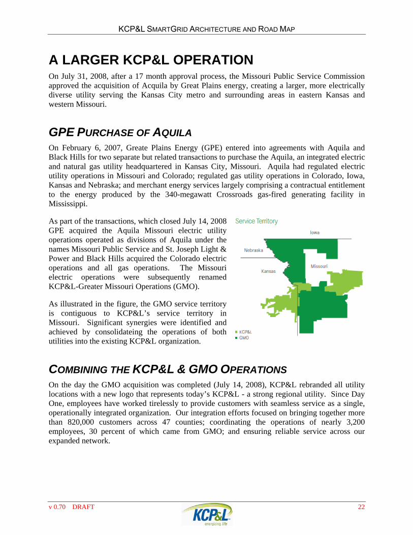
As illustrated in the figure the GMO service territory is contiguous to KCPampLrsquos service territory in Missouri Significant synergies were identified and achieved by consolidateing the operations of both utilities into the existing KCPampL organization
COMBINING THE KCPampL amp GMO OPERATIONS On the day the GMO acquisition was completed (July 14 2008) KCPampL rebranded all utility locations with a new logo that represents todayrsquos KCPampL - a strong regional utility Since Day One employees have worked tirelessly to provide customers with seamless service as a single operationally integrated organization Our integration efforts focused on bringing together more than 820000 customers across 47 counties coordinating the operations of nearly 3200 employees 30 percent of which came from GMO and ensuring reliable service across our expanded network
v 070 DRAFT 22
KCPampL SMARTGRID ARCHITECTURE AND ROAD MAP
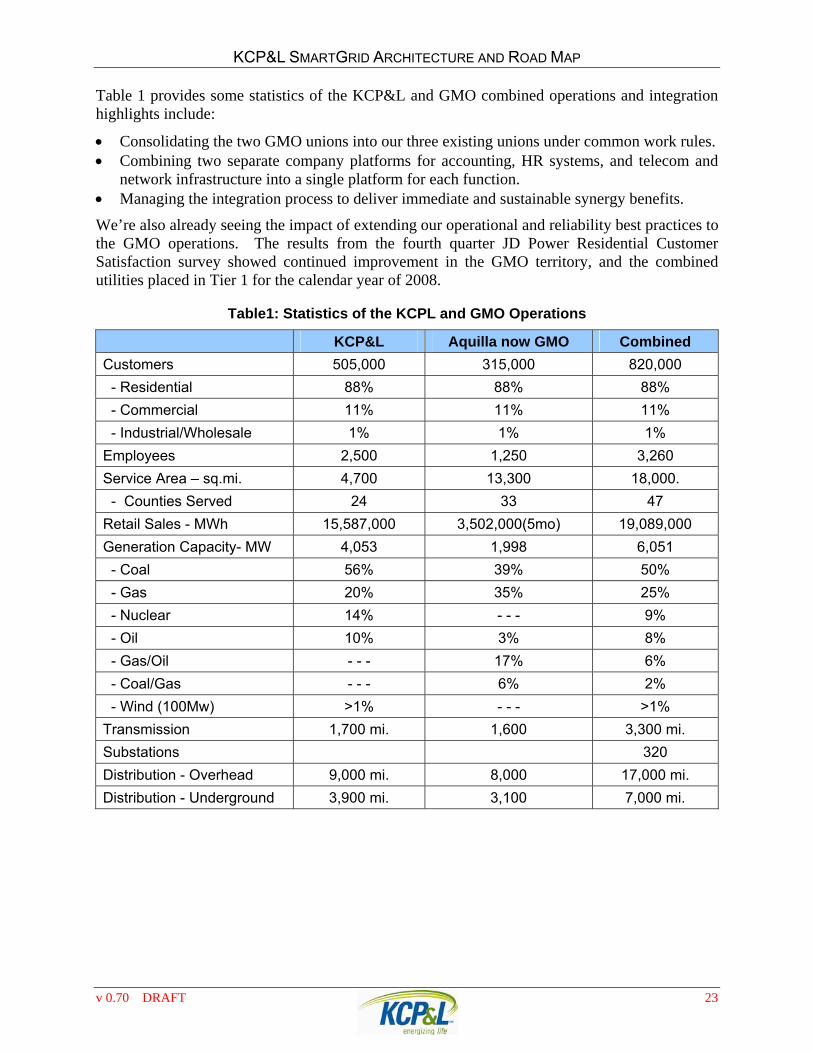
Table 1 provides some statistics of the KCPampL and GMO combined operations and integration highlights include
Consolidating the two GMO unions into our three existing unions under common work rules Combining two separate company platforms for accounting HR systems and telecom and
network infrastructure into a single platform for each function Managing the integration process to deliver immediate and sustainable synergy benefits
Wersquore also already seeing the impact of extending our operational and reliability best practices to the GMO operations The results from the fourth quarter JD Power Residential Customer Satisfaction survey showed continued improvement in the GMO territory and the combined utilities placed in Tier 1 for the calendar year of 2008
Table1 Statistics of the KCPL and GMO Operations
KCPampL Aquilla now GMO Combined
Customers 505000 315000 820000
- Residential 88 88 88
- Commercial 11 11 11
- IndustrialWholesale 1 1 1
Employees 2500 1250 3260
Service Area ndash sqmi 4700 13300 18000
- Counties Served 24 33 47
Retail Sales - MWh 15587000 3502000(5mo) 19089000
Generation Capacity- MW 4053 1998 6051
- Coal 56 39 50
- Gas 20 35 25
- Nuclear 14 - - - 9
- Oil 10 3 8
- GasOil - - - 17 6
- CoalGas - - - 6 2
- Wind (100Mw) gt1 - - - gt1
Transmission 1700 mi 1600 3300 mi
Substations 320
Distribution - Overhead 9000 mi 8000 17000 mi
Distribution - Underground 3900 mi 3100 7000 mi
v 070 DRAFT 23
KCPampL SMARTGRID ARCHITECTURE AND ROAD MAP
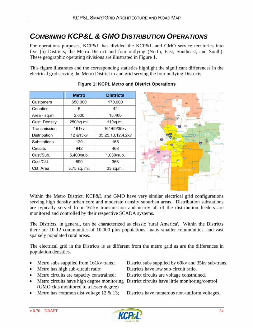
COMBINING KCPampL amp GMO DISTRIBUTION OPERATIONS For operations purposes KCPampL has divided the KCPampL and GMO service territories into five (5) Districts the Metro District and four outlying (North East Southeast and South) These geographic operating divisions are illustrated in Figure 1
This figure illustrates and the corresponding statistics highlight the significant differences in the electrical grid serving the Metro District to and grid serving the four outlying Districts
Figure 1 KCPL Metro and District Operations
Metro Districts
Customers 650000 170000
Counties 5 42
Area - sqmi 2600 15400
Cust Density 250sqmi 11sqmi
Transmission 161kv 1616935kv
Distribution 12 amp13kv 3525131242kv
Substations 120 165
Circuits 942 468
CustSub 5400sub 1030sub
CustCkt 690 363
Ckt Area 375 sq mi 33 sqmi
Within the Metro District KCPampL and GMO have very similar electrical grid configurations serving high density urban core and moderate density suburban areas Distribution substations are typically served from 161kv transmission and nearly all of the distribution feeders are monitored and controlled by their respective SCADA systems
The Districts in general can be characterized as classic rural America Within the Districts there are 10-12 communities of 10000 plus populations many smaller communities and vast sparsely populated rural areas
The electrical grid in the Districts is as different from the metro grid as are the differences in population densities
Metro subs supplied from 161kv trans District subs supplied by 69kv and 35kv sub-trans Metro has high sub-circuit ratio Districts have low sub-circuit ratio Metro circuits are capacity constrained District circuits are voltage constrained Metro circuits have high degree monitoring District circuits have little monitoringcontrol
(GMO ckts monitored to a lesser degree) Metro has common distvoltage 12 amp 13 Districts have numerous non-uniform voltages
v 070 DRAFT 24
KCPampL SMARTGRID ARCHITECTURE AND ROAD MAP
COMBINING KCPampL amp GMO OPERATIONS SYSTEMS At the time of the merger the Delivery organization included Customer Services Distribution Operations Energy Solutions Information Technology and Transmission Services all areas that directly touch customers Thatrsquos why it was so important to a single division that the transition goes smoothly
KCPampL goal for the transition was lsquoseamlessrsquo Day 1 customer service Customers will receive one bill format and will call a single number to report service interruptions or make billing inquiries One location will provide quick-response service relaying needs to appropriate service territories Employees may have multiple computer screens but customers wonrsquot know that
While operating redundant computer systems for the two operations was a short term stop-gap method to provide transparent service it would not achieve the level of desired synergies expected for the merged company To obtain the synergies and increased performance of staff and the grid system consolidation needed to occur as rapidly as possible The following are some of the key Operations Systems that needed to be integrated to support the Day 1 vision
Customer Information System (CIS) Aquila and KCPampL each used different versions of the same CIS platform Because each system is in need of upgrade in the next few years the decision was made to forgo consolidation until the time of upgrade Aquila bill formats were modified to be consistent with KCPampL formats and the KCPampL WEB portal is used to access both systems
Work Management System (WMS) Both Aquila and KCPampL used the Logica STORMS work management system On Day 1 these two systems were consolidated into the KCPampL STORMS astatine
Geographic Information System (GIS) Both Aquila and KCPampL each had GIS systems containing electronic representations of transmission and distribution facilities After careful review the Aquila GIS data was exported and merged into the KCPampL GIS
Outage Management System (OMS) Both Aquila and KCPampL each had OMS systems for processing light-out and trouble call The Aquila OMS was home-grown and after review it was determined that the KCPampL OMS would be used for both operations These systems are planned to be consolidated approximately Day 1+365 after the GIS data combination is complete
EMSSCADA (EMS) Both Aquila and KCPampL each had EMSSCADA systems monitoring and control of the transmission network and substation devices KCPampL was in the process of implementing the latest version of the ABB EMSSCADA system The GMO EMSSCADA functions will be migrated to the KCPampL EMSSCADA system
v 070 DRAFT 25
KCPampL SMARTGRID ARCHITECTURE AND ROAD MAP
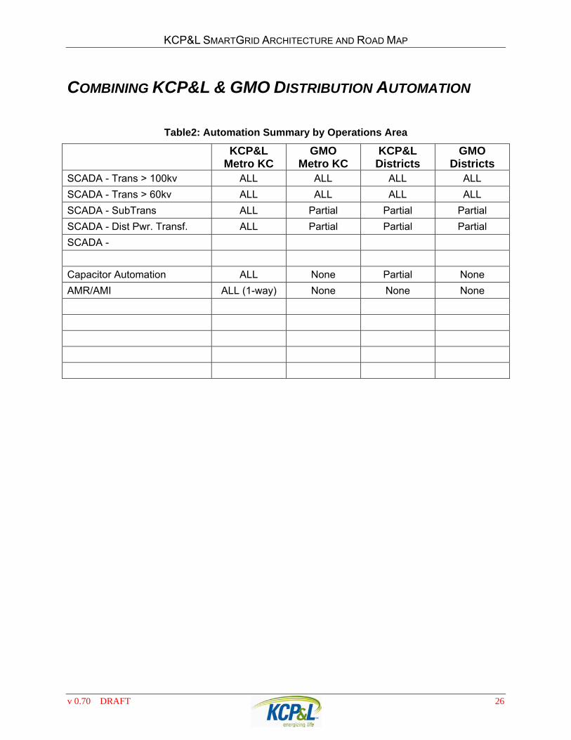
COMBINING KCPampL amp GMO DISTRIBUTION AUTOMATION
Table2 Automation Summary by Operations Area
KCPampL Metro KC
GMO Metro KC
KCPampL Districts
GMO Districts
SCADA - Trans gt 100kv ALL ALL ALL ALL
SCADA - Trans gt 60kv ALL ALL ALL ALL
SCADA - SubTrans ALL Partial Partial Partial
SCADA - Dist Pwr Transf ALL Partial Partial Partial
SCADA -
Capacitor Automation ALL None Partial None
AMRAMI ALL (1-way) None None None
v 070 DRAFT 26
KCPampL SMARTGRID ARCHITECTURE AND ROAD MAP
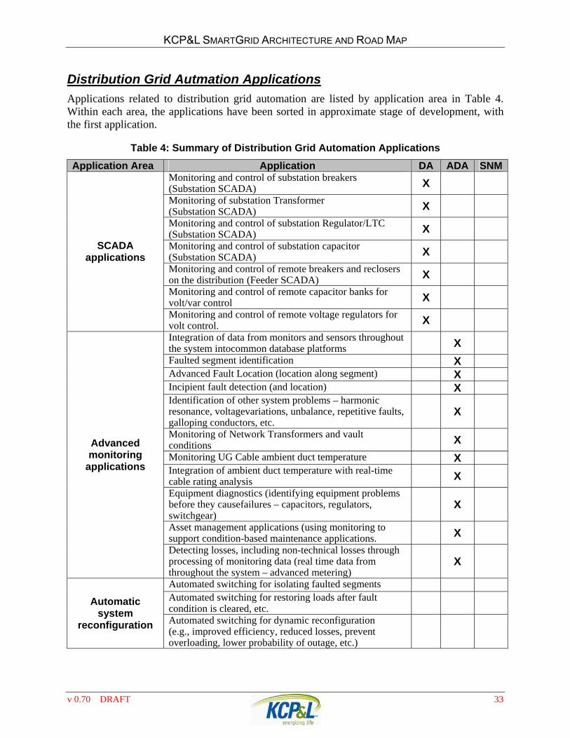
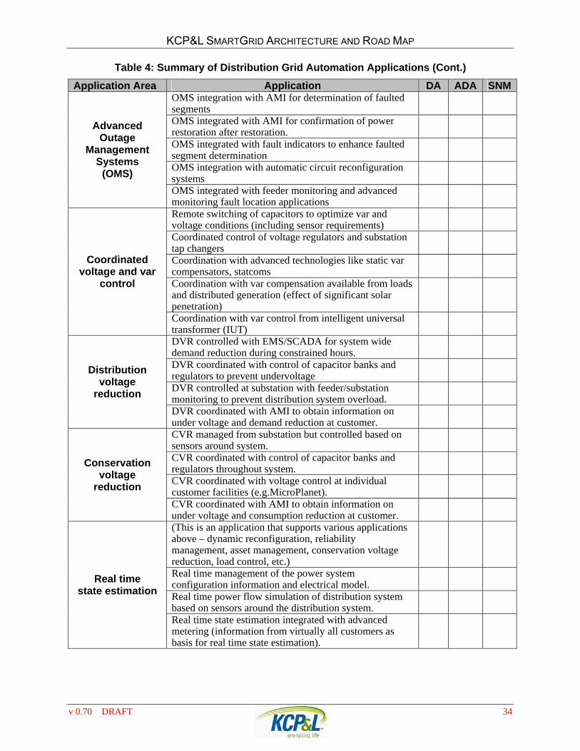
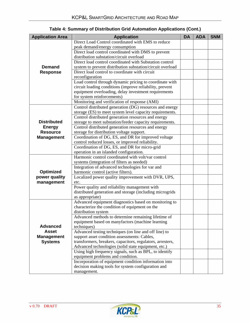
DISTRIBUTION GRID AUTOMATION APPLICATIONS AND TECHNOLOGIES This section characterizes the broad range of distribution grid automation applications and technologies and develops a comprehensive list of Distribution Grid Automation applications to consider when developing the SmartGrid architecture and road map
BACKGROUND AND DEFINITION OF DISTRIBUTION GRID
AUTOMATION FUNCTIONS Advanced information technology databases communication and controls are increasingly making a vast array of new distribution grid automation applications possible To the extent they are economic andor promote other policy goals KCPampL has the ability to build these technologies into its distribution system While many of the grid automation applications apply to a broad range of systems it is important to recognize that there are a number of different types of distribution systems that have different characteristics Applications that provide positive value in some part of the system may not be applicable or have positive economics in other parts of the system The major categories of system types are the following
Urban networks These systems supply high density loads that may be a combination of commercial facilities residential and light industrial loads They will typically be underground systems and may already be network configurations
Suburban systems These systems are characterized by moderate load density and a variety of load types They may be a combination of overhead and underground systems with a general trend towards increasing the penetration of underground distribution They are typically radial primary systems that may have open tie points between feeders
Rural systems These systems will typically be overhead radial circuits that are less likely to have open tie points to other feeder circuits They may be very long primary distribution systems (eg 20 miles and more)
Special systems Special systems may supply premium power parks office parks or other special groups of loads Special designs (eg microgrids) and technologies (eg custom power technologies) may be justified for these systems based on the needs of the end users supplied There may be special contracts associated with the customers on these systems
Automated Grid Delivering Energy and Information Traditional distribution systems were designed to perform one function to distribute electrical energy to end-users Increasingly distribution systems are delivering electrical energy and information between participants system operators and system components As demand response and other Distributed Energy Resources (DER) penetration of the grid increases the lines between electricity supplier and consumer blur because many of participants will assume both roles Similarly the exchange of information is multi-directional and will facilitate system
v 070 DRAFT 27
KCPampL SMARTGRID ARCHITECTURE AND ROAD MAP
operation and potentially enable decisions on whether to ldquosupplyrdquo or ldquouserdquo electrical energy based on dynamic rather than static prices
To exchange electricity and information the automated grid will contain two interrelated components
1 A communication architecture to facilitate the system monitoring and control functions of the automated system Ideally this will be migrating to open systems that will allow integration of technologies and components from multiple vendors
2 New electrical architectures and protection systems that enable an interoperable network of components
These two components are synergistic and inter-related with each other and together they comprise the automated distribution system The communication and information protocols required by the automated grid comprise a good number of the applications identified in this section
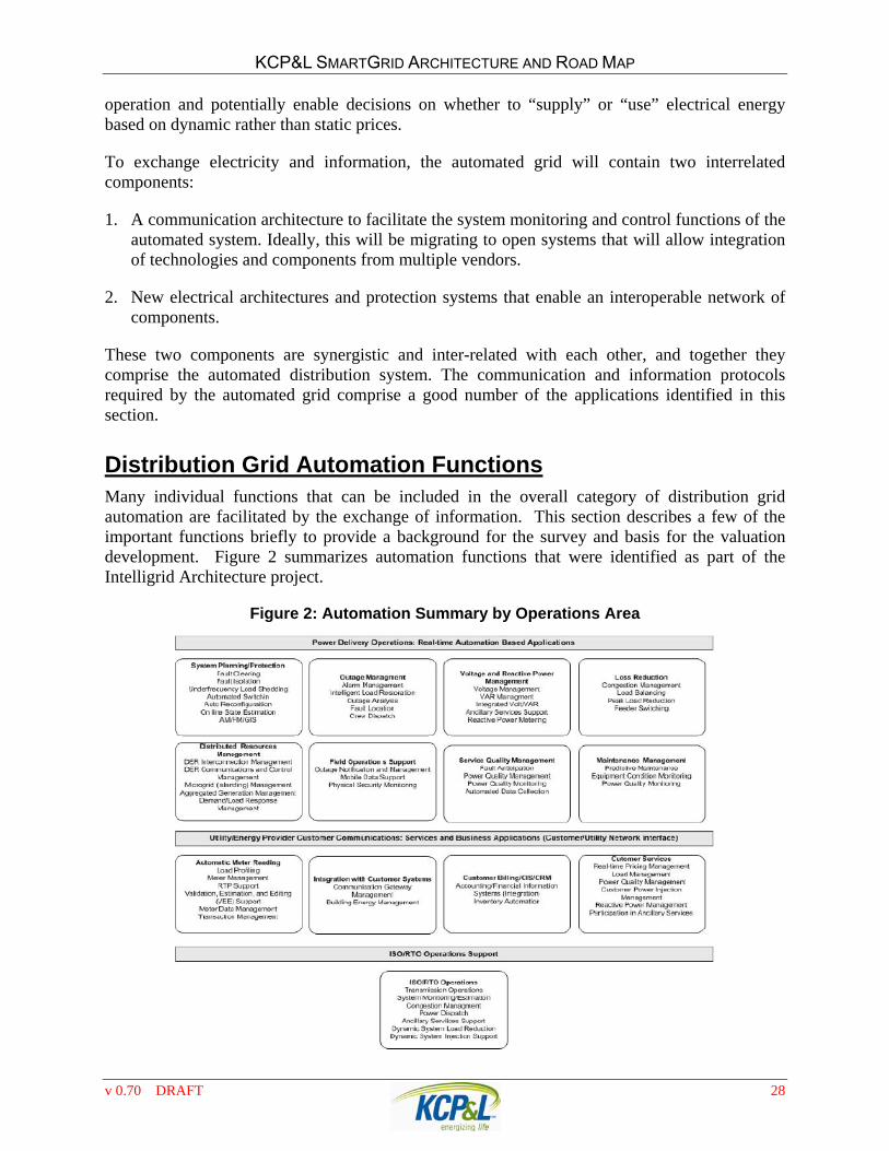
Distribution Grid Automation Functions Many individual functions that can be included in the overall category of distribution grid automation are facilitated by the exchange of information This section describes a few of the important functions briefly to provide a background for the survey and basis for the valuation development Figure 2 summarizes automation functions that were identified as part of the Intelligrid Architecture project
Figure 2 Automation Summary by Operations Area
v 070 DRAFT 28
KCPampL SMARTGRID ARCHITECTURE AND ROAD MAP
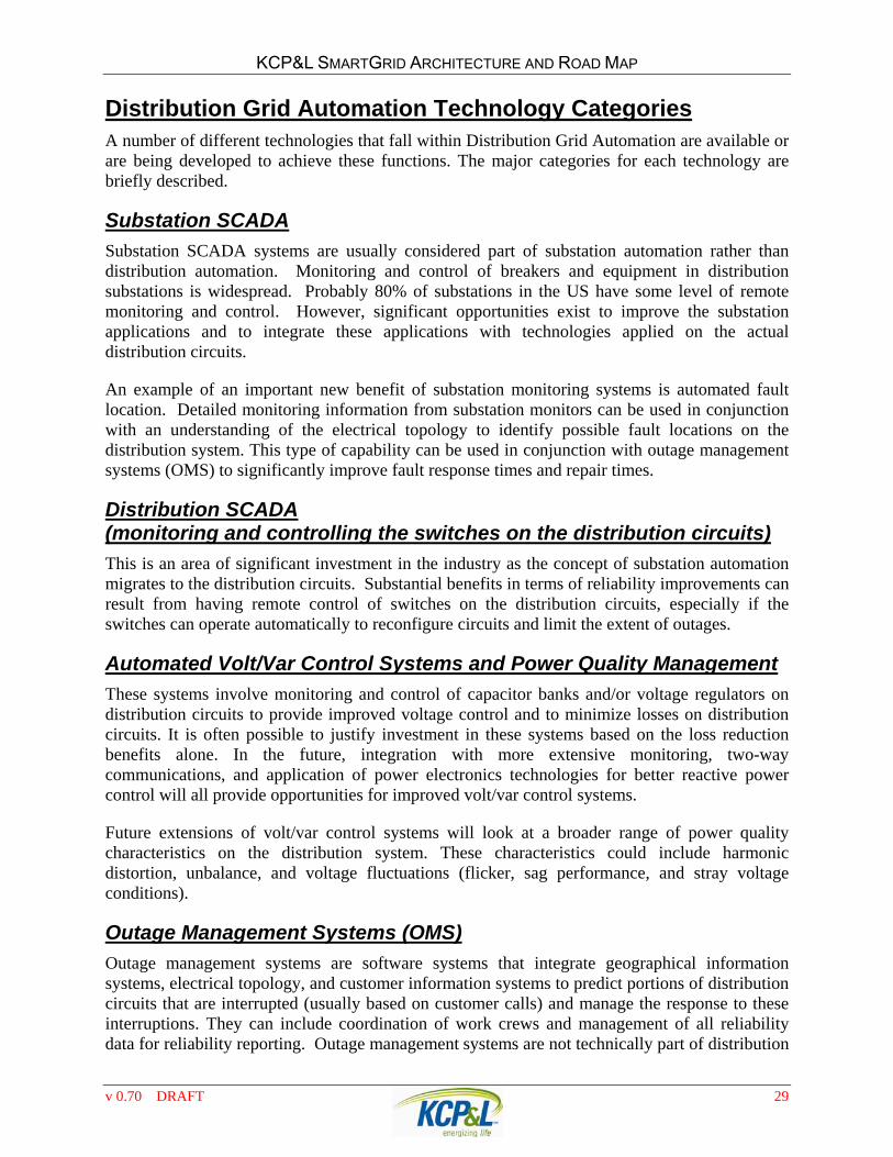
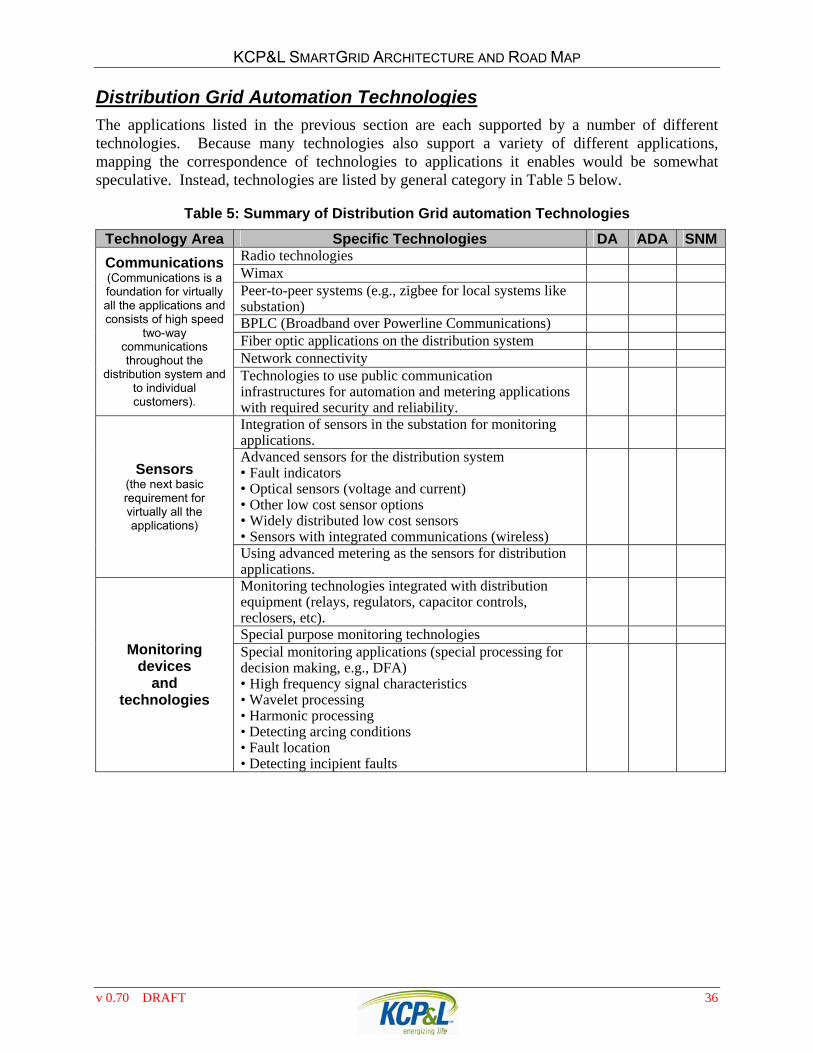
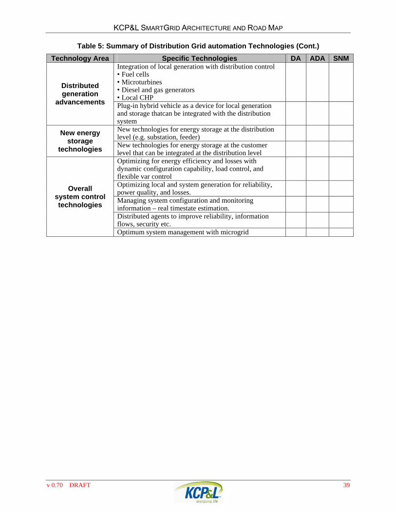
Distribution Grid Automation Technology Categories A number of different technologies that fall within Distribution Grid Automation are available or are being developed to achieve these functions The major categories for each technology are briefly described
Substation SCADA
Substation SCADA systems are usually considered part of substation automation rather than distribution automation Monitoring and control of breakers and equipment in distribution substations is widespread Probably 80 of substations in the US have some level of remote monitoring and control However significant opportunities exist to improve the substation applications and to integrate these applications with technologies applied on the actual distribution circuits
An example of an important new benefit of substation monitoring systems is automated fault location Detailed monitoring information from substation monitors can be used in conjunction with an understanding of the electrical topology to identify possible fault locations on the distribution system This type of capability can be used in conjunction with outage management systems (OMS) to significantly improve fault response times and repair times
Distribution SCADA (monitoring and controlling the switches on the distribution circuits)
This is an area of significant investment in the industry as the concept of substation automation migrates to the distribution circuits Substantial benefits in terms of reliability improvements can result from having remote control of switches on the distribution circuits especially if the switches can operate automatically to reconfigure circuits and limit the extent of outages
Automated VoltVar Control Systems and Power Quality Management
These systems involve monitoring and control of capacitor banks andor voltage regulators on distribution circuits to provide improved voltage control and to minimize losses on distribution circuits It is often possible to justify investment in these systems based on the loss reduction benefits alone In the future integration with more extensive monitoring two-way communications and application of power electronics technologies for better reactive power control will all provide opportunities for improved voltvar control systems
Future extensions of voltvar control systems will look at a broader range of power quality characteristics on the distribution system These characteristics could include harmonic distortion unbalance and voltage fluctuations (flicker sag performance and stray voltage conditions)
Outage Management Systems (OMS)
Outage management systems are software systems that integrate geographical information systems electrical topology and customer information systems to predict portions of distribution circuits that are interrupted (usually based on customer calls) and manage the response to these interruptions They can include coordination of work crews and management of all reliability data for reliability reporting Outage management systems are not technically part of distribution
v 070 DRAFT 29
KCPampL SMARTGRID ARCHITECTURE AND ROAD MAP
automation but it is critical that automated systems for distribution be coordinated closely with outage management systems
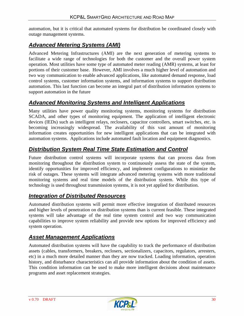
Advanced Metering Systems (AMI)
Advanced Metering Infrastructures (AMI) are the next generation of metering systems to facilitate a wide range of technologies for both the customer and the overall power system operation Most utilities have some type of automated meter reading (AMR) systems at least for portions of their customer base However AMI involves a much higher level of automation and two way communication to enable advanced applications like automated demand response load control systems customer information systems and information systems to support distribution automation This last function can become an integral part of distribution information systems to support automation in the future
Advanced Monitoring Systems and Intelligent Applications
Many utilities have power quality monitoring systems monitoring systems for distribution SCADA and other types of monitoring equipment The application of intelligent electronic devices (IEDs) such as intelligent relays reclosers capacitor controllers smart switches etc is becoming increasingly widespread The availability of this vast amount of monitoring information creates opportunities for new intelligent applications that can be integrated with automation systems Applications include automated fault location and equipment diagnostics
Distribution System Real Time State Estimation and Control
Future distribution control systems will incorporate systems that can process data from monitoring throughout the distribution system to continuously assess the state of the system identify opportunities for improved efficiency and implement configurations to minimize the risk of outages These systems will integrate advanced metering systems with more traditional monitoring systems and real time models of the distribution system While this type of technology is used throughout transmission systems it is not yet applied for distribution
Integration of Distributed Resources
Automated distribution systems will permit more effective integration of distributed resources and higher levels of penetration on distribution systems than is current feasible These integrated systems will take advantage of the real time system control and two way communication capabilities to improve system reliability and provide new options for improved efficiency and system operation
Asset Management Applications
Automated distribution systems will have the capability to track the performance of distribution assets (cables transformers breakers reclosers sectionalizers capacitors regulators arresters etc) in a much more detailed manner than they are now tracked Loading information operation history and disturbance characteristics can all provide information about the condition of assets This condition information can be used to make more intelligent decisions about maintenance programs and asset replacement strategies
v 070 DRAFT 30
KCPampL SMARTGRID ARCHITECTURE AND ROAD MAP
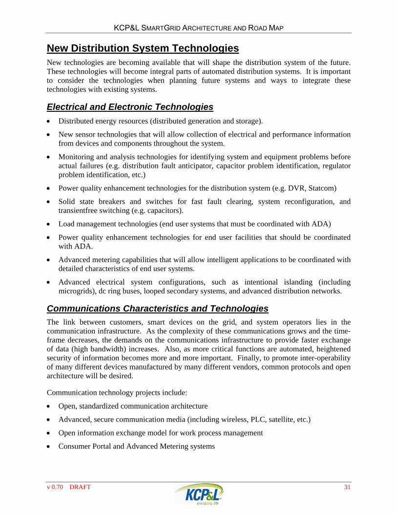
New Distribution System Technologies New technologies are becoming available that will shape the distribution system of the future These technologies will become integral parts of automated distribution systems It is important to consider the technologies when planning future systems and ways to integrate these technologies with existing systems
Electrical and Electronic Technologies
Distributed energy resources (distributed generation and storage)
New sensor technologies that will allow collection of electrical and performance information from devices and components throughout the system
Monitoring and analysis technologies for identifying system and equipment problems before actual failures (eg distribution fault anticipator capacitor problem identification regulator problem identification etc)
Power quality enhancement technologies for the distribution system (eg DVR Statcom)
Solid state breakers and switches for fast fault clearing system reconfiguration and transientfree switching (eg capacitors)
Load management technologies (end user systems that must be coordinated with ADA)
Power quality enhancement technologies for end user facilities that should be coordinated with ADA
Advanced metering capabilities that will allow intelligent applications to be coordinated with detailed characteristics of end user systems
Advanced electrical system configurations such as intentional islanding (including microgrids) dc ring buses looped secondary systems and advanced distribution networks
Communications Characteristics and Technologies
The link between customers smart devices on the grid and system operators lies in the communication infrastructure As the complexity of these communications grows and the time-frame decreases the demands on the communications infrastructure to provide faster exchange of data (high bandwidth) increases Also as more critical functions are automated heightened security of information becomes more and more important Finally to promote inter-operability of many different devices manufactured by many different vendors common protocols and open architecture will be desired
Communication technology projects include
Open standardized communication architecture
Advanced secure communication media (including wireless PLC satellite etc)
Open information exchange model for work process management
Consumer Portal and Advanced Metering systems
v 070 DRAFT 31
KCPampL SMARTGRID ARCHITECTURE AND ROAD MAP
Sensing and monitoring devices implementing features of new communications architecture and with integrated intelligent applications that become an integral part of overall system control schemes
Real time state estimation and predictive systems (including fault simulation modeling) to continuously assess the overall state of the distribution system and predict future conditions providing the basis for system optimization
Advanced control systems to optimize performance of the entire distribution system for efficiency asset management reliability quality and security
Load management and real time pricing systems that integrate with end user and DER systems to optimize overall system performance and efficiency
Asset management and work management systems that integrate with intelligent monitoring systems customer information systems and forecasting tools to optimize investments and maintenance based on the specific requirements of individual systems
Distribution Grid Automation Categories The SmartGrid team has identified a comprehensive list of specific distribution grid automation applications and technologies that have potential for inclusion in the KCPampL SmartGrid portfolio at some point on the RoadMap continuum The distinction between applications and technologies is subtle but is often important A technology by itself does not provide any specific value rather it is how that technology is used to make changes to the way the grid operates that provides value Therefore for assessment of the value of grid automation we focus on applications recognizing that there may be one or more technologies that enable that application to be implemented
Each of the applications and technologies has been categorized as DA (Distribution Automation) (ADA) Advancing Distribution Automation or (SNM) SmartGrid Network Management The distinction of these Distribution Grid Automation classifications may not be a fine like but can be generally divided based on the characteristics summarized in Table 3
Table 3 Differences between DA ADA and SNM classifications
Distribution Automation Advanced Distribution Automation SmartGrid Network Management Focused on automated and remote operation of basic distribution circuit switching functions
Focused on complete automation of all the controllable equipment and functions on the distribution system to improve operation of the system ADA takes DA to a higher level with enhanced monitoring analysis and control
Focused on the economic integration of consumer and utility distributed and renewable energy resources into distribution networks
Device integration primarily to Distribution SCADA system
Distribution SCADA system integrated to DMS and other distribution analytical applications
DMSSCADA integration with AMI MDM and other customermarket analytical systems to initiate DERDR pricing signals
Communications primarily use client-server serial protocols
Device operability requires client server device communications
Applications related to distribution grid automation are listed by application area in Table 4 Within each area the applications have been sorted in approximate stage of development with the first application
Table 4 Summary of Distribution Grid Automation Applications
Application Area Application DA ADA SNMMonitoring and control of substation breakers (Substation SCADA) X
Monitoring of substation Transformer (Substation SCADA) X
Monitoring and control of substation RegulatorLTC (Substation SCADA) X
Monitoring and control of substation capacitor (Substation SCADA) X
Monitoring and control of remote breakers and reclosers on the distribution (Feeder SCADA) X
Monitoring and control of remote capacitor banks for voltvar control X
SCADA applications
Monitoring and control of remote voltage regulators for volt control X
Integration of data from monitors and sensors throughout the system intocommon database platforms
X
Faulted segment identification X Advanced Fault Location (location along segment) X Incipient fault detection (and location) X Identification of other system problems ndash harmonic resonance voltagevariations unbalance repetitive faults galloping conductors etc
X
Monitoring of Network Transformers and vault conditions
X
Monitoring UG Cable ambient duct temperature X Integration of ambient duct temperature with real-time cable rating analysis
X
Equipment diagnostics (identifying equipment problems before they causefailures ndash capacitors regulators switchgear)
X
Asset management applications (using monitoring to support condition-based maintenance applications
X
Advanced monitoring
applications
Detecting losses including non-technical losses through processing of monitoring data (real time data from throughout the system ndash advanced metering)
X
Automated switching for isolating faulted segments Automated switching for restoring loads after fault condition is cleared etc
Automatic system
reconfiguration Automated switching for dynamic reconfiguration (eg improved efficiency reduced losses prevent overloading lower probability of outage etc)
v 070 DRAFT 33
KCPampL SMARTGRID ARCHITECTURE AND ROAD MAP
Table 4 Summary of Distribution Grid Automation Applications (Cont)
Application Area Application DA ADA SNMOMS integration with AMI for determination of faulted segments
OMS integrated with AMI for confirmation of power restoration after restoration
OMS integrated with fault indicators to enhance faulted segment determination
OMS integration with automatic circuit reconfiguration systems
Advanced Outage
Management Systems
(OMS)
OMS integrated with feeder monitoring and advanced monitoring fault location applications
Remote switching of capacitors to optimize var and voltage conditions (including sensor requirements)
Coordinated control of voltage regulators and substation tap changers
Coordination with advanced technologies like static var compensators statcoms
Coordination with var compensation available from loads and distributed generation (effect of significant solar penetration)
Coordinated voltage and var
control
Coordination with var control from intelligent universal transformer (IUT)
DVR controlled with EMSSCADA for system wide demand reduction during constrained hours
DVR coordinated with control of capacitor banks and regulators to prevent undervoltage
DVR controlled at substation with feedersubstation monitoring to prevent distribution system overload
Distribution voltage
reduction
DVR coordinated with AMI to obtain information on under voltage and demand reduction at customer
CVR managed from substation but controlled based on sensors around system
CVR coordinated with control of capacitor banks and regulators throughout system
CVR coordinated with voltage control at individual customer facilities (egMicroPlanet)
Conservation voltage
reduction
CVR coordinated with AMI to obtain information on under voltage and consumption reduction at customer
(This is an application that supports various applications above ndash dynamic reconfiguration reliability management asset management conservation voltage reduction load control etc)
Real time management of the power system configuration information and electrical model
Real time power flow simulation of distribution system based on sensors around the distribution system
Real time state estimation
Real time state estimation integrated with advanced metering (information from virtually all customers as basis for real time state estimation)
v 070 DRAFT 34
KCPampL SMARTGRID ARCHITECTURE AND ROAD MAP
Table 4 Summary of Distribution Grid Automation Applications (Cont)
Application Area Application DA ADA SNMDirect Load Control coordinated with EMS to reduce peak demandenergy consumption
Direct load control coordinated with DMS to prevent distribution substationcircuit overload
Direct load control coordinated with Substation control system to prevent distribution substationcircuit overload
Direct load control to coordinate with circuit reconfiguration
Load control through dynamic pricing to coordinate with circuit loading conditions (improve reliability prevent equipment overloading delay investment requirements for system reinforcements)
Demand Response
Monitoring and verification of response (AMI) Control distributed generation (DG) resources and energy storage (ES) to meet system level capacity requirements
Control distributed generation resources and energy storage to meet substationfeeder capacity requirements
Control distributed generation resources and energy storage for distribution voltage support
Coordination of DG ES and DR for improved voltage control reduced losses or improved reliability
Distributed Energy
Resource Management
Coordination of DG ES and DR for micro-grid operation in an islanded configuration
Harmonic control coordinated with voltvar control systems (integration of filters as needed)
Integration of advanced technologies for var and harmonic control (active filters)
Localized power quality improvement with DVR UPS etc
Optimized
power quality management
Power quality and reliability management with distributed generation and storage (including microgrids as appropriate)
Advanced equipment diagnostics based on monitoring to characterize the condition of equipment on the distribution system
Advanced methods to determine remaining lifetime of equipment based on manyfactors (machine learning techniques)
Advanced testing techniques (on line and off line) to support asset condition assessments Cables transformers breakers capacitors regulators arresters Advanced technologies (solid state equipment etc)
Using high frequency signals such as BPL to identify equipment problems and condition
Advanced Asset
Management Systems
Incorporation of equipment condition information into decision making tools for system configuration and management
v 070 DRAFT 35
KCPampL SMARTGRID ARCHITECTURE AND ROAD MAP
Distribution Grid Automation Technologies
The applications listed in the previous section are each supported by a number of different technologies Because many technologies also support a variety of different applications mapping the correspondence of technologies to applications it enables would be somewhat speculative Instead technologies are listed by general category in Table 5 below
Table 5 Summary of Distribution Grid automation Technologies
Technology Area Specific Technologies DA ADA SNMRadio technologies Wimax Peer-to-peer systems (eg zigbee for local systems like substation)
BPLC (Broadband over Powerline Communications) Fiber optic applications on the distribution system Network connectivity
Communications (Communications is a foundation for virtually all the applications and consists of high speed
two-way communications throughout the
distribution system and to individual customers)
Technologies to use public communication infrastructures for automation and metering applications with required security and reliability
Integration of sensors in the substation for monitoring applications
Advanced sensors for the distribution system bull Fault indicators bull Optical sensors (voltage and current) bull Other low cost sensor options bull Widely distributed low cost sensors bull Sensors with integrated communications (wireless)
Sensors
(the next basic requirement for virtually all the applications)
Using advanced metering as the sensors for distribution applications
Monitoring technologies integrated with distribution equipment (relays regulators capacitor controls reclosers etc)
Special purpose monitoring technologies Monitoring
devices and
technologies
Special monitoring applications (special processing for decision making eg DFA) bull High frequency signal characteristics bull Wavelet processing bull Harmonic processing bull Detecting arcing conditions bull Fault location bull Detecting incipient faults
v 070 DRAFT 36
KCPampL SMARTGRID ARCHITECTURE AND ROAD MAP
Table 5 Summary of Distribution Grid automation Technologies (Cont)
Technology Area Specific Technologies DA ADA SNMIEC 61850 models for all distribution substation equipment
Extension of IEC 61850 throughout the distribution system
Extension of information models to distributed generation and storage technologies
Extension of information models to new technologies (static compensators IUT etc) Integration of data with Common Information Model (CIM) to facilitate use of information in a wide variety of applications from real time state estimation to asset management
Monitoring
data integration
Standard database designs for distribution information management
Controllable vacuum breaker and SF6 breaker for fast switching applications and controlled zero crossing applications
Conventional
switchgear advancements Integration of monitoring and communications with
breaker for distribution information management
Solid state switch for fast fault clearing Solid state switch for reduced transients during capacitor switching
Solid state switch for fast system reconfiguration
Solid state switch
Solid state switch to facilitate microgrids Meters that can provide gateway to load control and load management through pricing information
Meters that can provide interface for direct load control in times of emergency and during system reconfiguration efforts
Meters that integrate with OMS Advanced meters
Meters that can integrate with distribution information systems (eg for real time state estimation)
Advanced reclosers for integration with automatic reconfiguration systems
Adaptive protection systems that can be coordinated with changing system configurations and conditions
Adaptive protection systems that can be controlled based on environmental conditions (eg storms)
Protection systems that provide integrated monitoring information for overall distribution management systems
Advanced protection systems
Advanced expulsion and current limiting fuses for fast clearing of faults with integrated sensors and communications
v 070 DRAFT 37
KCPampL SMARTGRID ARCHITECTURE AND ROAD MAP
Table 5 Summary of Distribution Grid automation Technologies (Cont)
Technology Area Specific Technologies DA ADA SNM Transformers bull High efficiency bull Integrated sensors and communications for loading hotspotscondition assessment
Capacitors bull Integrated sensors and communications bull Integrated protection
Regulators bull Improved switching for fast voltage control bull Integration with monitoring and control systems bull Intelligent algorithms for coordination with distributed generation
Distribution equipment advanced
technologies
Arresters bull Integrated monitoring and communications to identify problems bull Dynamic arrester characteristics for control of different types of transients and overvoltages
Advancements in underground cable design installation and reliability to improve overall system reliability
Integration of sensors and communications with underground cables
Advanced conductors for improved reliability with animals and trees
Advanced conductors with sensors to detect loading arcing etc
Conductors
Superconducting cables Static var systems Statcom Integration of var control with local var sources (local generation local capacitors local technologies like statcoms that also provide power quality improvement)
Active filters (integrated harmonic control) Intelligent universal transformer (including support of dc supply options for facilities)
Advanced CVR technology for local voltage sag ride through
Advanced power electronic
technologies
Advanced UPS for local reliability improvement and possible integration with microgrids
Harmonic filters on the distribution system Static var systems and statcoms for fast voltage control DVR for local voltage sag ride through support
Power quality improvement technologies Advanced UPS for local reliability improvement (and
also can provide var support)
v 070 DRAFT 38
KCPampL SMARTGRID ARCHITECTURE AND ROAD MAP
Table 5 Summary of Distribution Grid automation Technologies (Cont)
Technology Area Specific Technologies DA ADA SNM Integration of local generation with distribution control bull Fuel cells bull Microturbines bull Diesel and gas generators bull Local CHP
Distributed generation
advancements Plug-in hybrid vehicle as a device for local generation and storage thatcan be integrated with the distribution system
New technologies for energy storage at the distribution level (eg substation feeder)
New energy storage
technologies New technologies for energy storage at the customer level that can be integrated at the distribution level
Optimizing for energy efficiency and losses with dynamic configuration capability load control and flexible var control
Optimizing local and system generation for reliability power quality and losses
Managing system configuration and monitoring information ndash real timestate estimation
Distributed agents to improve reliability information flows security etc
Overall system control technologies
Optimum system management with microgrid
v 070 DRAFT 39
KCPampL SMARTGRID ARCHITECTURE AND ROAD MAP
SMARTGRID ARCHITECTURE The grid that is in place at KCPampL today is substantially ldquosmartrdquo having benefited from decades of power engineering expertise The systems put into place already execute a variety of sophisticated system operations and protection functions In addition it should be noted that what is now termed ldquosmart gridrdquo has been under development by the KCPampL and the industry for many years Much of the integration has been done through incremental applications of technology and fitting them into system operations as well as possible Many of these are custom engineered integrations work a rounds and proprietary systems The smart grid will include many incremental enhancements to the existing KCPampL electric power infrastructure That said KCPampL desires to shift gears and fully integrate dispersed systems including visions of integrating dynamic new customer systems applications improved system automation and control as well as the projected siting of significantly more renewable resources This compels KCPampL to develop a SmartGrid Architecture since the company needs to move from one-off and custom integration to mass deployment with a high degree of interoperability
DEVELOPING A SMARTGRID ARCHITECTURE Since 2001 EPRI has managed a collaborative research development and demonstration (RDampD) process that has accelerated the industrys migration towards a SmartGrid KCPampL has been an active funder and participant in this RDampD effort KCPampL has leveraging EPRIs extensive work in developing a smart grid vision and roadmaps for other utilities in developing the SmartGrid Architecture Vision for KCPampL outlined in this section
Architecture Defined Architecture is defined as
Architecture The structure of components their relationships and the principles and guidelines governing their design and evolution over time
This definition adopted by the Department of Defense is based on an IEEE Standard There are other definitions but this definition is sufficient for the purpose of developing our SmartGrid Architecture It is important that the architecture for the ultimate fully functional SmartGrid take a high level perspective to define how the various elements are to be brought together to meet the business regulatory and technical objectives for KCPampL The perspectives of a SmartGrid Architecture must encompass all levels of grid operation from ISORTO to communications within customer premise and end-use equipment Based on the architecture system engineers create designs Designs are where technology and standards become important
v 070 DRAFT 40
KCPampL SMARTGRID ARCHITECTURE AND ROAD MAP
Multidisciplinary Nature of the Smart Grid The power grid of today was primarily built upon the disciplines surrounding power engineering with some assistance from other disciplines The smart grid will require a more complete interdisciplinary approach to adequately describe The power system and information technology as well as communication infrastructure and architectural components must be included in the picture Architecture includes the distributed computing infrastructure that requires systems engineering as well as communications software engineering data management network management architecture development and other related disciplines that are evolving Thus a high level description of a smart grid is the merging of two infrastructures composed of the electric power infrastructure and a communications infrastructure that enables and intelligent grid
Technology Categories of the Smart Grid If the grid is going to be smart it will use a well orchestrated combination of a wide variety of equipment hardware control algorithms and communications networks These smart grid components can be related by different technology levels and major business function Both utility business and technical perspectives together assist an understanding of how the elements come together and what is needed to enable the smart grid Figure 6 depicts a structured method by which to identify the various technical elements of the smart grid
The smart grid is comprised of various levels of technology ranging from power delivery infrastructure (that is physical assets and energy resources) plus sensors and control devices to communication infrastructure that gathers data from sensors and measurement systems The information is used to determine the state of the power system and transform its operation maintenance and planning using knowledge derivable from a rich set of collected data This transformation depicts a grid enabled to be operated planned and maintained more intelligently through development and deployment of key technologies that enable these characteristics
As depicted in Figure 6 traditional business areas include generation transmission distribution and external operations applicable to enhancing customer service Different classes of technologies and applications are typically found within each business unit at each hierarchical level The following hierarchy is used to characterize technologies at different levels as depicted in Figure 1
Power system resources This level designates the traditional physical assets that constitute the power system (cables transformers lines meters) as well as the resources connected to it (wind farms PV installations CHP systems storage PHEV)
Controls and sensors This level designates the equipment and materials installed on the power system that allow and facilitate the control or the measurement of the different assets
Communication infrastructure This level designates the combination of the systems needed to support the two-way exchange of information with the controls and sensors level It is constituted of the physical infrastructure and the associated protocols
v 070 DRAFT 41
KCPampL SMARTGRID ARCHITECTURE AND ROAD MAP
Figure 1 ndash Technical Elements of the SmartGrid
Data integration This level designates the information technology systems needed to store the data provided through the communication infrastructure layer and allow their use by the relevant applications to transform it into information Interoperability between systems is a critical issue at this level for applications to leverage the data collected and extract maximum value
Applications This level designates the business processes supported by human interfaces providing decision support Information collected at the data integration level is used by business process supporting applications to improve efficiency reliability and cost effectiveness of power system operations planning and maintenance
SMARTGRID ARCHITECTURE VIEWS So that the proposed SmartGrid Architecture can be more clearly understood it is being presented in six (6) largely complimentary viewpoints Each viewpoint represents a different technical perspective and answers a different set of requirements These viewpoints are
Electrical Grid Monitoring and Control Application Systems Communications Network View Data Integration amp Interoperability Security Regulatory
v 070 DRAFT 42
KCPampL SMARTGRID ARCHITECTURE AND ROAD MAP
Grid Monitoring and Control View This view designates the grid monitoring operation and control process performed unattended and those supported by human interaction The grid monitoring operation and control functions of the new smart grid will be both hierarchical and distributed as illustrated in Figure 2
The hierarchical levels are significant because communication between levels is generally controlled to some degree Applications at a higher level may only see an aggregated view of applications at a lower level This does not mean that lower level data is hidden from a higher level only that the specifics of how to communicate and the semantics of lower level applications may be wrapped by a higher level communications mechanism and semantics
Regional Transmission Organization (RTO) ndash At this level the Southwestern Power Pool will be responsible for Inter-RTO and inter-utilityIPP exchanges within the SPP The grid monitoring and control at this level will be automated and centrally operator monitored
Utility Generation amp Transmission (UGT) - At this level KCPampL will be responsible for its internal central generation station dispatch and transmission system operation The grid monitoring and control at this level will be automated and centrally operator monitored
Figure 2 ndash Electrical Grid Monitoring and Control Architectural View
Distribution System Operations (DSO) - At this level KCPampL Distribution Operations will be responsible for the utility wide distribution system operation and control The grid monitoring and control at this level will be automated and centrally operator monitored
Automated Metering Infrastructure (AMI) - At this level KCPampL Metering Operations will be responsible for the utility wide meter reading operation and connectdisconnects The AMI monitoring operation and control at this level will be automated and centrally operator managed
Distribution Substation Automation (DSA) - At this level each distribution substation control module will be responsible substation-wide monitoring and control This includes status of devices within the substation and devices on the circuits emanating from the substation The grid monitoring and control at this level will be automated and centrally monitored by the higher DSO control system and operators
Feeder Intelligent End Devices (IED) ndash At this level each IED will be responsible for monitoring local conditions and acting upon these local conditions in a pre-programmed manner IEDs are distribution equipment with microprocessor based control and communication modules These include RTUs AMI meters Distributed Energy Resources (DER) and DA devices The IED monitoring and control operation will be monitored by the appropriate DSA control module and centrally by the DSO control system and operators
Building Energy Management System (BMS) ndash At this level the BMS will be responsible for monitoring local conditions price and control signals and consumption information and acting upon these conditions in a pre-programmed manner The BMS should receive premise consumption information from the local AMI meter and may receive price and control signals from either the AMI meter or through an Internet gateway The only monitoring of the BMS activity will be via the resulting consumption changes recorded via the AMI meter
Consumer End Device (CED) ndash At this level the CED or appliance will be responsible to price and control signals received from the BMS andor the utility AMI meter and acting upon these signals in a pre-programmed manner The only monitoring of the CED activity will be via the resulting consumption changes recorded via the AMI meter and feedback from any direct utility controlled device (thermostat AC control pool pump etc)
Wholesale Electric Markets (WEM) ndash At this level
Utility Central Generation(UCG) ndash At this level the
Independent Power Producer(IPP) ndash At this level the
Wholesale Energy Supplier(WES) ndash At this level the
v 070 DRAFT 44
KCPampL SMARTGRID ARCHITECTURE AND ROAD MAP
Application Systems View This view designates the business processes supported by human interfaces providing decision support The Information collected at the data integration level is used by business process supporting applications to improve efficiency reliability and cost effectiveness of power system operations planning and maintenance The currently identified potential applications needed to support the SmartGrid have been organized into logical groupings so they can be more easily correlated to the other Architecture views These application groupings are graphically depicted in Figure 3
Wholesale Electric Markets (WEM)
Energy Trading and Settlement Market Operations
Regional Transmission Organization (RTO)
Regional Power Scheduling Market Monitoring Reliability amp Congestion Management Wide Area Measurement (Phasor Measurement Units) Expansion Planning
Utility Central Generation (UCG)
Generation Monitoring amp Control Plant Operation Management Systems
Figure 3 ndash Application Systems Architectural View
GMS - Generation Management System TMS - Transmission Management System T-SCADA - Transmission System Control and Data Acquisition TDH ndash Transmission Data Historian TRP ndash Transmission Reporting Portal (dashboard) T-AMS ndash Transmission Asset Management System T-GIS ndash Transmission Geographic Information System TTS ndash Transmission Training Simulator
Distribution Network Management Systems
DMS - Distribution Management System ADA ndash Advanced Distribution Automation DERM ndash Distributed Energy Resource Management DRM ndash Demand Response Management OMS ndash Outage Management System MWFM ndash Mobile WorkForce Management D-SCADA - Distribution System Control and Data Acquisition DDH ndash Distribution Data Historian DRP ndash Distribution Reporting Portal (dashboard) D-AMS ndash Distribution Asset Management System D-GIS ndash Distribution Geographic Information System DTS ndash Distribution Training Simulator
Distribution Substation Automation Systems
VVM ndash Integrated VoltVar Management FDS ndash Fault Detection and amp Switching STS ndash Substation Training Simulator SDH ndash Substation Data Historian DER - Distributed Energy Resource Management TOU ndash
Measurement Management Systems
MDM ndash Meter Data Management AMR ndash Automated Meter Reading MOM ndash Meter Operations Management RTP ndash Real-Time Pricing CPM ndash Consumer Energy Portal Management CGM ndash Consumer Gateway Management
v 070 DRAFT 46
KCPampL SMARTGRID ARCHITECTURE AND ROAD MAP
Consumer Energy Management Systems
C-EMP ndash Consumer Energy Management Portal (via Internet) C-EMS ndash Consumer Energy Management System C-RTP ndash Consumer Real-Time Pricing Response C-RUD ndash Real-Time Usage Display
Communications Network View This view designates the combinations of communication networks needed to support the two-way exchange of information through all levels of architecture
The EPRI IECSA (IntelliGrid) project identified twenty one (21) distinct computing environments required to support the entire ultimate SmartGrid These are illustrated in Figure 4 and described in IECSA Volume IV Appendix E IECSA defines an Environment as a logical grouping of power system requirements that could be addressed by a similar set of distributed computing technologies With a particular environment the information exchanges used to perform power system operational functions have very similar architectural requirements including their
Configuration requirements Quality of Service Requirements Security requirements Data Managements requirements
Figure 4 ndash IECSA Environments in Power System Operations
v 070 DRAFT 47
KCPampL SMARTGRID ARCHITECTURE AND ROAD MAP
As can be seen in Figure 4 the management of the power system infrastructure is increasingly reliant on the information infrastructure as automation continues to replace manual operations and is therefore affected by any problems that the information infrastructure might suffer
The communications network view for the information networks proposed to support the deployment of the Smarter Grid is depicted in Figure 5 and the characteristics of each network layer are described in the following subsections As the Smarter Grid evolves into the SmartGrid communication technologies will evolve and the information network requirements will increase The communications technologies associated with this network architecture view will also evolve
The following subsections present the significant network communication characteristics for each of the network layers and describes the EICSA SmartGrid Communication Environment that must be supported by each layer
Enterprise Network
The KCPampL IT Enterprise Network Layer will provide the back-office communications required for the various SmartGrid systems CIS ERP systems and the EMSSCADA systems
Recommended Network Technology
Quality of Service - 999 Availability Time-Sync Data High Speed lt 1 sec Application Layer - SNTP Transport Protocol ndash TCP Network Protocol ndash IP v4 or v6 Link and Physical ndash 1Gb Ethernet
IESCA 7 Intra-Control Center Environment
Quality of Service - 999 Availability Time-Sync Data Data Exchange - IEC-60870-6 ICCP
IESCA 8 Inter-Control Center Environment
Quality of Service - 999 Availability Time-Sync Data Medium Speed lt 10 sec Data Exchange - IEC-61968 and Enterprise Service Bus (ESB)
Smarter Grid Wide Area Network
The Smarter Grid Wide Area Network (WAN) layer requires the expansion of the KCPampL IT IP WAN to all substations to provide the backhaul communications required for the grid automation and AMI
Recommended Network Technology
Quality of Service - 999 Availability Time-Sync Data High Speed lt 1 sec Application Layer - SNTP Transport Protocol ndash TCP Network Protocol ndash IP v4 or v6 Link and Physical ndash Private Fiber Microwave andor Leased Lines
IESCA 5 Critical Operations DAC and SCADA Environment
Quality of Service - 999 Availability Time-Sync Data High Speed lt 1 sec Data Exchange - IEC-61850 (DNP30IP as a transition) Data Exchange - IEC-60870-6 ICCP
IESCA 6 Non-Critical Operations DAC Data Acquisition Environment
Quality of Service - 999 Availability Medium Speed lt 10 sec Data Exchange - IEC-61850 (DNP30IP as a transition) Data Exchange - IEC-60870-6 ICCP
v 070 DRAFT 49
KCPampL SMARTGRID ARCHITECTURE AND ROAD MAP
IESCA 15 DER Monitoring and Control Environment
Quality of Service - 999 Availability Time-Sync Data High Speed lt 1 sec Data Exchange - IEC-61850 (DNP30IP as a transition) Data Exchange - IEC-62350 DER General Data Exchange - IEC-61400-25 DER Wind Power
IESCA 18 Customer [Meter] to ESP Environment
Quality of Service - 990 Availability Time-Sync Data Medium Speed lt 10 sec Data Exchange - ANSI C1219 Meter Data Tables
IESCA 11 Control Center to Customer Environment
Quality of Service - 990 Availability Medium Speed lt 10 sec Data Exchange - Smart Energy Profile
Substation Process Network
An IP based Substation Process Network (SPN) will be deployed within each distribution substation to provide the communication requirements for substation automation
Recommended Network Technology
Quality of Service - 99999 Availability High Data Precision Ultra-High Speed lt 4 ms Application Layer - SNTP Transport Protocol ndash TCP Network Protocol ndash IP v4 or v6 Link and Physical ndash Private 100 Mb Ethernet or 100Kb Wireless FAN
Quality of Service - 99999 Availability High Data Precision Ultra-High Speed lt 4 ms Data Exchange - IEC-61850
IESCA 5 Critical Operations DAC and SCADA Environment
Quality of Service - 999 Availability Time-Sync Data High Speed lt 1 sec Data Exchange - IEC-61850 (DNP30IP as a transition)
IESCA 6 Non-Critical Operations DAC Data Acquisition Environment
Quality of Service - 999 Availability Medium Speed lt 10 sec Data Exchange - IEC-61850 (DNP30IP as a transition)
Field Area Network (FAN)
A wireless Field Area Network (FAN) will be deployed to provide the private field communications required for grid automation and AMI
Recommended Network Technology
Quality of Service - 999 Availability Time-Sync Data High Speed lt 1 sec Application Layer - SNTP
v 070 DRAFT 50
KCPampL SMARTGRID ARCHITECTURE AND ROAD MAP
Transport Protocol ndash TCP Network Protocol ndash IP v6 Link and Physical ndash Private 100Kb Wireless FAN
IESCA 4 Inter-Field Equipment Environment
Quality of Service - 999 Availability Time-Sync Data High Speed lt 1 sec Data Exchange - IEC-61850 (DNP30IP as a transition)
IESCA 5 Critical Operations DAC and SCADA Environment
Quality of Service - 999 Availability Time-Sync Data High Speed lt 1 sec Data Exchange - IEC-61850 (DNP30IP as a transition) Data Exchange - IEC-60870-6 ICCP
IESCA 6 Non-Critical Operations DAC Data Acquisition Environment
Quality of Service - 999 Availability Medium Speed lt 10 sec Data Exchange - IEC-61850 (DNP30IP as a transition)
IESCA 15 DER Monitoring and Control Environment
Quality of Service - 999 Availability Time-Sync Data High Speed lt 1 sec Data Exchange - IEC-61850 (DNP30IP as a transition) Data Exchange - IEC-62350 DER General Data Exchange - IEC-61400-25 DER Wind Power
IESCA 18 Customer [Meter] to ESP Environment
Quality of Service - 990 Availability Time-Sync Data Medium Speed lt 10 sec Data Exchange - ANSI C1219 Meter Data Tables
IESCA 11 Control Center to Customer Environment
Quality of Service - 990 Availability Medium Speed lt 10 sec Data Exchange - Smart Energy Profile
Home Area Network ndash Meter Gateway
A ZigBee communication module in the AMI meters will be used to establish a communication gateway to the HAN (Home Area Network) ldquosmartrdquo appliances and Home Energy Management Systems This wireless gateway will provide real-time customer usage data directly from the meter and relay pricing and other communications from the back office applications
Recommended Network Technology
Quality of Service - 990 Availability Medium Speed lt 10 sec Network and Physical ndash ZigBee Wireless HAN
IESCA 11 Control Center to Customer Environment
Quality of Service - 990 Availability Medium Speed lt 10 sec Data Exchange - Smart Energy Profile
v 070 DRAFT 51
KCPampL SMARTGRID ARCHITECTURE AND ROAD MAP
KCPL 21 ESP Meter to Customer
Quality of Service - 990 Availability Medium Speed lt 10 sec Data Exchange - Smart Energy Profile (Consumption Data)
Home Area Network ndash Broadband Gateway
Some customers may desire to have more direct oversight of their energy consumption but may not want to manage a Home Energy Management System For these customers our architecture includes a KCPampL or third-party WEB hosted home automation and energy management systems are being developed and will become commonplace This broadband gateway will connect to a local gateway appliance provide a WEB based user interface and obtain pricing and other communications from the back office applications
Recommended Network Technology
Quality of Service - 990 Availability High Speed lt 1 sec Network and Physical ndash Public Broadband Internet
IESCA 11 Control Center to Customer Environment
Quality of Service - 990 Availability High Speed lt 1 sec Data Exchange - Smart Energy Profile
Home Area Network
A wireless or power line carrier Home Area Network (HAN) will be deployed by the customer to provide the private in-home communications required for homebuilding automation energy management security and entertainment
IESCA 16h Intra-Customer Site Environment - Home
Data Exchange - Smart Energy Profile others Network and Physical ndash ZigBee Wireless HAN Network and Physical - Power Line Carrier HAN
IESCA 16c Intra-Customer Site Environment - Commercial
Data Exchange - Smart Energy Profile others Network and Physical ndash ZigBee Wireless HAN Network and Physical - Power Line Carrier HAN
IESCA 16i Intra-Customer Site Environment - Industrial
Data Exchange - Smart Energy Profile others Network and Physical - Power Line Carrier HAN
v 070 DRAFT 52
KCPampL SMARTGRID ARCHITECTURE AND ROAD MAP
Private vs Public Communication Infrastructure
Traditionally the power utility communications infrastructure typically comprises multiple physically separate networks each dedicated to support specific applications and functions For example a SONETSDH based network is used to carry real-time SCADA traffic while engineers needing access substation information use dial-up modems Further a separate TDM-based network may exist to support PBX-based voice communications among the substations and control centers
With the advent of new high-speed communications technologies the Communication Architecture as presented recommends that these multiple communications paths be consolidated into the Corporate IT WAN and that all KCPampL networks be implemented on private communications infrastructure
Why Not the Internet The public Internet is a very powerful all-pervasive medium It can provide very inexpensive means exchange information with a variety of other entities The Internet is being used by some utilities for exchanging sensitive market information retrieving power system data and even issuing some control commands to generators Although standard security measures such as security certificates are used a number of vulnerabilities still exist
By using the Corporate IT WAN the KCPampL SmartGrid system designs can still leverage the vast amount of research and development into Internet Protocols (IP) and technologies They will just be implemented over a private Intranet instead of the public Internet to minimize the exposure to cyber security attacks
Role of Public Carriers As information becomes increasingly vital to power system operations utilities want to ensure continued support for these information flows while providing greater insight into the state of the communications network and the computer systems in the field reducing latency
Where it has proven to be cost effective KCPampL has chosen to construct and own significant portions of the WAN communications infrastructure This includes a significant amount of fiber links in the metro and microwave links in the rural areas Dedicated leased communication links have been used to provide the network path where KCPampL communications is not available Although leased from a public carrier the dedicated link is not impacted by other users of the carrier
The FAN network to support DA and AMI significantly increases the number of nodes that must be connected to the network There are two fundamental reasons for recommending that KCPampL construct and operate a private wireless FAN instead of using a public wireless carrier operational reliability and financial
Operational reliability is critical for the DA devices and functions History has shown that during times of emergencies and natural disasters public carriers become congested and communications becomes unreliable The public carriers have been unwilling or unable to guarantee communications during high usage times
v 070 DRAFT 53
KCPampL SMARTGRID ARCHITECTURE AND ROAD MAP
Using a public wireless carrier also creates additional ongoing operational costs If we used wireless public carrier exclusively the Smarter Grid deployment would require at least 1000 AMI take out points and 4000 DA device connections at a cost of nearly $3 million per year Using a 10yr life and a 12 cost of money this would equate to an upfront capital expenditure of approximately $15 million
Data Management Integration amp Interoperability This level designates the information technology systems needed to store the data provided through the communication infrastructure layer and allow their use by the relevant applications to transform it into information Interoperability between systems is a critical issue at this level for applications to leverage the data collected and extract maximum value
Data Management
Data Management Considerations The amount of data being collected or capable of being collected will increase exponentially with the implementation of the Smart Grid This rapid expansion of data management results from the fact that more field devices are being installed and that these field devices are becoming more intelligent both in what power system characteristics they can capture and also in what calculations and algorithms they can execute which result in even more data
As distribution automation extends communications to devices on feeders as substation automation expands the information available for retrieval by substation planners protection engineers and maintenance personnel and as more power system asset information is stored electronically in Geographical Information even more varieties and volumes of data will be need to be maintained and managed
Data management is a complex issue encompassing many aspects of data accuracy acquisition and entry storage and access consistency across systems maintenance backup and logging and security Data management must address a complex set of issues which include the following services
1 Validation of source data and data exchanges 2 Ensuring data is up-to-date 3 Management of time-sensitive data flows and timely access to data by multiple users 4 Management of data consistency and synchronization across systems 5 Management of data formats in data exchanges 6 Management of transaction integrity (backup and rollback capability) 7 Management of the naming of data items (namespace allocation and naming rules) 8 Data Accuracy 9 Data Acquisition 10 Data Entry 11 Data Storage and Access Management 12 Data Consistency across Multiple Systems 13 Database Maintenance Management 14 Data Backup and Logging 15 Application Management
v 070 DRAFT 54
KCPampL SMARTGRID ARCHITECTURE AND ROAD MAP
No single cross-industry technology addresses all of these issues but multiple solutions are available for different aspects See IECSA Volume IV Appendix F for discussion of each
Data Management Architecture This view presents the Data Management Architecture that will be implemented as the SmartGrid evolves In traditional grid control systems all data management has been centralized Data was collected remotely at the field RTUs and transported back to a central control center for use in applications presentment storage or disposal As deployment of SmartGrid expands several things are happening
The amount of data being collected or capable of being collected will increase exponentially IED provide the ability to process data locally and take local actions independently IEDs can also increase the amount of data needed to collect and actions to log and report Data storage is very inexpensive and has been added to IEDs meters and other field devices
Base on the current trends the Data Management Architecture presented in Figure 6 is hierarchical and distributed very complimentary to the hierarchical and distributed nature of the other architectural components
AMI Head End Monthly Read Detail Monthly Alarm logs
MDM Historical Read Detail Historical Alarm Logs
Sub Controller Seq Events Log Device Status
Device Controller Operation History Operation Status
DMS amp OMS Device Status Outage Status
RT Historian Outage History
IED
RT Processing
Operations
Enterprise
T-SCADA Seq Events Log Device Status
Device Controller Operation History Operation Status
EMS amp GMS Device Status
RT Historian
v 070 DRAFT 55
KCPampL SMARTGRID ARCHITECTURE AND ROAD MAP
The hierarchical levels are significant because data transfer between the levels is generally controlled to some degree Data available at a higher level may only be an aggregated view of data available at a lower level This does not mean that lower level data is unavailable just that the detailed data has not been needed at the higher level to support normal business operations
Data Management Principles The Data Management Architecture presented is a complete opposite paradigm of traditional control systems Figure x presents the data management principles that should be used to guide the system designs when implementing this architecture
AMI Example DA Example
1 Data should be processed as close to the collection point as possible
Meter broadcasts use every 5 sec to customer
2 IEDs and process controllers internally store data for limited periods to support local processing and higher level system needs
Meter can store 45 days of TOU usage and midnight read data in meter memory
3 Data should only be communicated to another device or higher level if there is a real business need for the data
Meter sends midnight read for all accounts TOU only sent for specified accounts
4 Data that is no longer needed is allowed to expire at the earliest possible time and at the lowest level
Meter data is allowed to expire at the meter after 45 days
5 At each level data should be managed by the most appropriate data management technology
At the system level meter data should be managed by a MDM system
6 Data achievable should occur at the enterprise level using the most appropriate data archival technology
A real-time historian should be used to archive any real-time data that needs to be archived
Integration amp Interoperability
Interoperability Goals - The ultimate goal of interoperability is to enable two independently developed devices to integrate their operations over a communications network Interoperability has been defined as
ldquoThe ability of two or more systems or components to exchange information and to use the information that has been exchangedrdquo7
While the concept appears simple on the surface the complexity of the systems or components requires a substantial amount of agreement in the way they interact Even relatively simple levels of interoperability require not only adherence to standards and agreement on use of those standards but technicians are also necessary to participate in setting up and configuring equipment Higher levels of interoperability are a fundamental requirement for SmartGrid systems and this includes the capabilities to enable the equipment to participate in the management of the system
v 070 DRAFT 56
KCPampL SMARTGRID ARCHITECTURE AND ROAD MAP
The concepts of lsquoPlug and Workrsquo (or lsquoPlug and Playrsquo) require more sophisticated levels of interoperability These capabilities enable you to plug in a new device application or system into an existing system and the existing system automatically incorporates the new equipment These levels of interoperability are strongly desired since it simplifies the human intervention required to manage systems However to achieve systems that are easier for humans to use requires a higher degree of internal sophistication Interoperability and interworkability are terms that must be more tightly defined within the industry The goal of interoperable systems can be very hard to achieve in a diverse environment with many different requirements many different vendors and a wide variety of standards Interoperability is particularly difficult where legacy systems prevent the use of more modern approaches No one answer exists on how to integrate these older less flexible systems but the following technologies and best practices can help toward that interoperability
Key Points of InteroperabilityndashAn additional principle states that while it is possible to standardize everything it is also possible to end up with so many standards that ultimately there are no standards Ultimately there must be a balance between components of a communications system that are rigidly standardized and those that are fairly flexible to be pioneered by market participants -- vendors customers etc
For the SmartGrid there will be an analogy between those key points of interoperability for power (60Hz 120VAC plug shape) that will be key to facilitating an explosion in goods and services that can interact using components referenced in the architecture Some key points of interoperability required for the SmartGrid are
Manufacturing IDsndashGlobally unique identifiers for the source of a component in a utility or other enterprise system
Serial numbersndashGlobally unique identifiers for instances of products
Standardized object modelsndashStandardized object models with lsquowell-knownrsquo names and formats for exchanging data among disparate applications and systems
Metadata representationndashMetadata is data that describes data The term lsquoRosersquo could be a persons name a flower a color or an acronym Metadata is the term that describes what the word Rose refers to in a given application Metadata is a powerful concept that can be used for embedded devices to exchange information and achieve higher levels of interoperability This lsquodatarsquo that describes data permits users applications and systems to access or lsquobrowsersquo the names and structures of object models in other systems as the key method for lsquodata discoveryrsquo
Internet and industry standardsndashUsing the Internet and other industry standards to take advantage of the effort used to develop them the resulting decrease in prices and the interoperability provided by them
Time synchronization over widespread geographic areasndashThe ability to define a common mechanism to obtain reliable global time synchronization for devices of any level of complexity
v 070 DRAFT 57
KCPampL SMARTGRID ARCHITECTURE AND ROAD MAP
The DOE NIST and FERC Roles The Department of Energy is the lead federal agency on the Smart Grid effort and the National Institute of Standards and Technology (NIST) is coordinating the development of interoperability standards for the project Interoperability standards are needed to ensure that software and hardware components from different vendors will work together seamlessly while cyber security standards will protect the multi-system network against natural or human-caused disruptions
The Energy Independence and Security Act (EISA) of 2007 charges NIST with primary responsibility to coordinate development of a framework that includes protocols and model standards for information management to achieve interoperability of smart grid devices and systems
The EISA-2007 also provides a mandates to FERC At any time the Institute [NIST] work has led to a sufficient consensus in the [FERC] Commissions judgment the Commission shall develop by rule such standards and protocols as may be necessary to ensure smart-grid functionality and interoperability in interstate transmission of electric power and regional and wholesale electric markets
NIST recently contracted with the Electric Power Research Institute Inc (EPRI) to help the agency develop an interim report on Smart Grid architecture and a standards roadmap EPRI also will support consensus-building activities to create an initial slate of Smart Grid standards By the end of 2009 NIST plans to submit these standards for review and approval by the Federal Energy Regulation Commission which has jurisdiction over interstate transport and sales of electric power
Evolving SmartGrid Interoperability Standards This section presents evolving SmartGrid interoperability standards needed to store and move the data through the communication infrastructure layers from device to device device to application and between applications With the work completed to date by NIST and EPRI it appears that the standards presented here will form the basis of the NIST SmartGrid Interoperability Framework The AMI and HAN integration standardization remains very polarized and will take longer for a standards path to materialize Interoperability between systems is a critical issue at this level for applications to leverage the data collected and extract maximum value
Common Information Model - IEC-61970 The IEC-61970 standard includes the Common Information Model (CIM) the Generic Interface Definition (GID) The purpose of the CIM is to produce standard interface specifications for plug-in applications for the electric utility industry A plug-in application is defined to be software that may be installed with minimal effort and no modification of source code
The CIM describes real-world objects in terms of classes attributes and relationships The CIM contains object types such as substations breakers as work orders as well as other objects typically found in an control systems (EMS SCADA DMS) or work and asset management systems Recently the CIM has been extended to include transmission reservation and energy
v 070 DRAFT 58
KCPampL SMARTGRID ARCHITECTURE AND ROAD MAP
scheduling information and work is ongoing to extend the CIM for additional distribution and customer energy management objects
System Interfaces for Distribution Management - IEC-61968 The IEC-61968 as depicted in Figure 7 is a 10 part standard that extends the CIM model for object and messaging definitions to support the enterprise back-office Distribution System Management functions of Asset Management (AMS) work management systems (WMS) Distribution Network Management (DNM) Outage Management Systems (OMS) Meter Data Management (MDM) Automated Meter Information (AMI) and Geographic Information Systems (GIS)
Figure 7 - IEC 61968-1 DMS Application Interface Reference Model
IEC 61968 Compliant Middleware Services
(NE)Network
ExtensionPlanning
(CS)CustomerSupport
(MR)Meter
Reading ampControl
(AM)Records amp
AssetManagement
(MC)Maintenance
ampConstruction
InterfaceStandard Part 4
InterfaceStandard Part 6
InterfaceStandard Part 7
InterfaceStandard Part 8
InterfaceStandard Part 9
(ACT)CustomerAccount
Management
(FIN)Financial
(PRM)Premises
(HR)Human
Resources
(EMS)Energy
Management ampEnergy Trading
(RET)Retail
InterfaceStandard Part 10
(SC)Supply
Chain andLogistics
(NO)Network
Operation
InterfaceStandard Part 3
(OP)OperationalPlanning amp
Optimization
InterfaceStandard Part 5
InterfaceStandard Part 10
InterfaceStandard Part 10
InterfaceStandard Part 10
InterfaceStandard Part 10
InterfaceStandard Part 10
InterfaceStandard Part 10
Electric Distribution NetworkPlanning Constructing
Maintaining and Operating
Generation and Transmission ManagementEnterprise Resource Planning Supply Chain and
General Corporate Services
Business FunctionsExternal To Distribution
Management
Distribution ManagementBusiness Functions
Inter-Control Center Communications - IEC-60870-6 (TASE2) The IEC-60870-6 Telecontrol Application Service Element 2 (TASE2) protocol (informally referred to as the InterControl Center Communications Protocol (ICCP)) was developed by IEC for data exchange over Wide Area Networks between a utility control center and other control centers other utilities power plants and substations
TASE2 is used in almost every utility for inter-control center communications between SCADA andor EMS systems Since it was first in the mid-1990s before the CIM object model it is limited to use to the object model that is in the specification
v 070 DRAFT 59
KCPampL SMARTGRID ARCHITECTURE AND ROAD MAP
Inter-Device Communication IEC-61850 The IEC-61850 standard describes physical field devices such as circuit breakers protection relays capacitor controllers and in recent additions distributed energy resources such as wind turbines diesel generators and fuel cells The 61850 Object Models are lsquonounsrsquo with predefined names and predefined data structures Objects are the data that is exchanged among different devices and systems
IEC-61850 was originally developed for intra-substation communications between devices and control systems The IEC-61850 standard includes a Substation Configuration Language (SCL) to define the inter-relationship of the substation equipment to each other and the ability for the protocol to lsquoself-describersquo the data to be reported by a particular device
Work is ongoing to harmonize the IEC-61870 and IEC-61850 standards and extend the IEC-61850 standard to include distribution line devices distributed energy resources and customer energy management objects
Inter-Device Communication DNP3-IP DNP was developed as a three-layer asynchronous protocol suitable for use on slow serial links and radios It incorporates the best features of the many proprietary protocols that preceded it and therefore has gained wide support and continues to be the dominate protocol in use throughout the North American electric utility industry
In 2000 the DNP technical Committee defined a specification for carrying DNP3 over TCPIP and UDPIP Because the WANLAN version is essentially the serial DNP3 encapsulated this makes it possible to connect serial DNP3 devices to WANLAN DNP3 devices using a variety of networking technologies
DNP3 does not support the CIM object models therefore it is considered to be a transitional protocol and may continue to be used as the SmartGrid evolves supporting existing legacy devices that cannot be replaced economically
Home Area Network - Smart Energy Profile The ZigBee Alliance is an association of companies working together to enable reliable cost effective low-power wirelessly networked monitoring and control products based the IEEE 802144 standard The alliance developed the Smart Energy Profile a set of messages for managing energy and communicating with thermostats and other smart appliances
Overall the AMI and HAN integration standardization remains very polarized and will take longer for a standards path to materialize However The Smart Energy Profile is gaining considerable traction as the application messaging protocol of choice HomePlug a major home-automation competitor has announced that it will adopt the Smart Energy Profile for its power-line carrier based system Smart Energy Profile 20 is currently under development and when released it will contain the messaging to support plug-in electric vehicles
Security View This view presents the security requirements and technologies envisioned to secure the SmartGrid
v 070 DRAFT 60
KCPampL SMARTGRID ARCHITECTURE AND ROAD MAP
Securing the SmartGrid
Security by obscurity is no longer an acceptable solution in the electrical power industry Protection and securing of networked communications intelligent equipment and the data and information that are vital to the operation of the future SmartGrid is one of the key drivers behind developing this Architecture Security View Cyber security faces substantial challenges both institutional and technical This discussion is intended to provide context to this complex topic as well as providing a pathway by which the company can work to develop a robust portfolio of technologies to meet the critical issues that encompass security Securing the SmartGrid faces multiple challenges from the following major trends
Need for greater levels of systems integration with a variety of business entities Increased use internet-based infrastructures that will comprise the future energy system The need for appropriate integration of existing or ldquolegacyrdquo systems with future systems Growing sophistication and complexity of integrated distributed computing systems Growing sophistication and threats from hostile communities
Security functions are integral to the designs of systems and must be planned and designed into systems from the start Planning for security in advance of deployment will provide a more complete and cost effective solution Additionally advanced planning will ensure that security services are supportable (may be cost prohibitive to retrofit into non-planned environments This means that security needs to be addressed at all levels of the architecture
Security is an ever evolving process and is not static It takes continual work and education to help the security processes keep up with the demands that will be placed on the systems Security will continue to be a race between corporate security policiessecurity infrastructure and hostile entities The security processes and systems will continue to evolve in the future By definition there are no communication connected systems that are 100 secure There will always be residual risks that must be taken into account and managed
Security Domains
The far reaching and complex nature of the SmartGrid dictates that no-single security policy can be developed to properly secure the SmartGrid The hierarchical nature of the technologies presented in the Communications Network and Grid Monitoring amp Control Architecture views provides for the security ldquocheck-pointsrdquo between control and network layers that may have different security requirements Therefore it is a natural extension for the Security Architecture to be constructed around Security Domains
v 070 DRAFT 61
KCPampL SMARTGRID ARCHITECTURE AND ROAD MAP
A Security Domain represents a set of resources (eg network computational and physical) that share a common security requirements and risk assessment For example within the bulk power system there are two distinct Security Domains NERC-CIP and NERC-nonCIP
While having different security requirements all Security Domains will be secured and managed through a consistent set of security policies and processes Secure connectivity data encryption firewall protection intrusion detection access logging change control and the audit reports associated with these applications will likely be required for all SmartGrid Security Domains
The following sections identify the security domains that must be addressed in SmartGrid Security planning and development
SD0 Internet
Policy Mgt Ownership Many Parties Net Mgt Many Parties End Device Access Consumer
SD1 HAN
Policy Consumer Ownership Consumer Net Mgt Consumer End Device Access Consumer
SD2 AMI-WAN
Policy Utility Ownership Utility amp Public Carrier Net Mgt Utility IT Telcom End Device Access Utility Metering Personnel
SD3 DA-WAN
Policy Utility Ownership Utility Net Mgt Utility IT Telcom End Device Access Utility Construction amp Eng Personnel
SD4 Substation SPN
Policy Utility Ownership Utility Net Mgt Utility IT Network amp Telcom End Device Access Utility Relay amp Eng Personnel
v 070 DRAFT 62
KCPampL SMARTGRID ARCHITECTURE AND ROAD MAP
SD5 Corp WAN
Policy Utility Ownership Utility amp Leased Private Net Mgt Utility IT Network amp Telcom End Device Access Utility IT Network amp Telcom
SD6 Corp LAN
Policy Utility Ownership Utility amp Leased Private Net Mgt Utility IT Network End Device Access Any KCPL Employee
SD7 DNMS LAN
Policy Utility Ownership Utility Net Mgt Utility IT Network End Device Access Authorized KCPL Employee
SD8 FERCNERC-nonCIP
Oversight FERCNERC Ownership Utility Net Mgt Utility IT Network End Device Access Authorized KCPL Employee
SD9 FERCNERC-CIP NERC-CIP compliance is mandated for the bulk power system Oversight FERCNERC Ownership Utility Net Mgt Utility IT Network End Device Access Limited-Authorized KCPL Employee Not all data are equal when it comes to sensitivity to security threats The key to assessing the sensitivity of data is to determine the impact both financial and societal on compromising its security and to determine the risk of that compromise occurring For instance the financial and societal impact of eavesdropping on the meter readings of a single residential home is far less than the impact of issuing unauthorized breaker-trip commands to high voltage transmission lines Therefore the primary need is the assessment of financial and societal costs of different security vulnerabilities along with the assessment of the financial and societal costs of implementing security measures The IECSA security strategy is documented in Appendix A for those technologies that have identified the issues in their respective environments (eg IEC61850) The security strategy for other technologiesapplications will have to be developed based on the requirements of the particular application and using the technologies and practices found in Appendix A
v 070 DRAFT 63
KCPampL SMARTGRID ARCHITECTURE AND ROAD MAP
v 070 DRAFT 64
KCPampL SMARTGRID ARCHITECTURE AND ROAD MAP
Regulatory View This view presents the regulatory influences and requirements that can become key to any successful SmartGrid deployment
Economic and Regulatory Policy
Business organizations require that the political and regulatory policies that govern commerce provide the proper environment andor incentives to build business relationships with other organizations some of which may be considered competitors This includes national stat and local governalce Interoperability betweek organizatons in differerent state and geographical regions may require regulatory alignment at the state level or a national policy to provide an environment conductive for business interoperability In addition policy can provide incentive and remove impediments for regional or national structures that facilitate interoperation
Jurisdictional Oversight
Utilities require that the political and regulatory policies of the jurisdictions within which they operate provide the proper environmt andor incentives to make the required investments in SmartGrid technologies and programs many of which may be contrary to traditional utility engineering and operating practices Proper regulatory policy can provide incentives and remove impediments for these and facilitate the transition to a modern SmartGrid
Transmission Grid Oversight For KCPampL the jurisdictional aspects of SmartGrid realated to the transmission grid are complicated for KCPampL by the fact that it operates in two states each with differing laws regulations and regulatory commissions and by multiple regional and federal agencies
FERC The Federal Energy Regulatory Commission (FERC) is an independent federal agency that regulates the interstate transmission of electricity natural gas and oil FERC has jurisdictional authority of the KCPampLs electric transmission grid
Regulates the transmission and wholesale sales of electricity in interstate commerce Ensures the reliability of high voltage interstate transmission system Monitors and investigates energy markets Uses civil penalties and other means against energy organizations and individuals who
violate FERC rules in the energy markets Licenses and inspects private municipal and state hydroelectric projects Oversees environmental matters related to natural gas and hydroelectricity projects and major
electricity policy initiatives
v 070 DRAFT 65
KCPampL SMARTGRID ARCHITECTURE AND ROAD MAP
NERC North American Electric Reliability Corporation (NERC) develops reliability standards for the North American bulk power system that are adopted by FERC Along with the Regional Reliability Organizations NERC has the legal authority from FERC to enforce compliance with NERC Reliability Standards which it achieves through a rigorous program of monitoring audits and investigations and the imposition of financial penalties and other enforcement actions for non-compliance
SPP The Southwest Power Pool (SPP) is a Regional Transmission Organization mandated by the FERC to ensure reliable supplies of power adequate transmission infrastructure and competitive wholesale prices of electricity As a NERC Regional Reliability Organizaton SPP oversees compliance enforcement and reliability standards development SPP has member utilities in nine states including KCPampL and KCPampL-GMO
State Regulatory Commissions The State Regulatory Commissions have jurisdictional authority many aspects of the transmission grid including the approval for the physical construction of electric generation and transmission facilities except for hydropower and certain electric transmission facilities located in National interest electric transmission corridors
Distribution Grid Oversight For KCPampL the jurisdictional aspects of SmartGrid related to the distribution grid are complicated by the fact that we operate in two states each with differing laws regulations and regulatory commissions
The Missouri Public Service Commission (MO-PSC) regulates investor-owned electric steam natural gas water and sewer and telephone companies Its mission is to ensure Missouri consumers have access to safe reliable and reasonably priced utility service while allowing those utility companies under our jurisdiction an opportunity to earn a reasonable return on their investment
The mission of the Kansas Corporation Commission (KCC) is to protect the public interest through impartial and efficient resolution of all jurisdictional issues The agency shall regulate rates service and safety of public utilities common carriers motor carriers and regulate oil and gas production by protecting correlative rights and environmental resources
State Regulatory Commissions While the MO-PSC and KCC have different areas of responsibly and different styles of proceeding both have jurisdictional authority over the utilities and operation of the electric delivery grid in their respective states They each
regulate the retail electricity and natural gas sales to consumers regulate the electric service territory of the utility determine if investments are prudent and set reasonable rate of return
v 070 DRAFT 66
KCPampL SMARTGRID ARCHITECTURE AND ROAD MAP
Both state commissions are currently considering three (3) new PURPA requirements that related directly to the SmartGrid
1) Rate Redesign to promote Energy Efficiency 2) SmartGrid Investment and 3) SmartGrid Information
KCPampL has recommended that the commissions use a collaborative workshop process to develop the framework for considering these issues The IL commission mandated that Ameren and Comm Edison participate in a formal state-wide SmartGrid Road Map
Successful collaboration with the Commissions Legislatures and Consumer Organizations on transitional issues will be key to achieving the level of consumer acceptance participation and enthusiasm in the new energy management concepts needed to make the SmartGrid deployment a success Inverted Block rate structures will be needed to promote energy efficiency and effective Time of Use rates will be needed to promote shifting energy consumption off-peak The new standard AMI meters are designed to easily support TOU rates with 4-daily usage times and 4-seasonal periods allowing for very flexible rate implementations
v 070 DRAFT 67
KCPampL SMARTGRID ARCHITECTURE AND ROAD MAP
KCPampL SMARTGRID ROADMAP
WHAT IS A SMARTGRID ROAD MAP In the previous section the SmartGrid Architecture for KCPampL was presented Realizing that the SmartGrid in complete vision cannot be built today but will instead develop over time a SmartGrid Road Map presents a plan for implementing the vision and functionality of the SmartGrid over time
DEVELOPING A SMARTGRID ROAD MAP The SmartGrid in complete vision cannot be built today but will instead develop over time Most utilities have a similar vision for an ultimate SmartGrid but will take different paths and time-lines in their respective SmartGrid deployments These paths will be influenced by regulatory and business drivers and the mix of technologies that a company has currently installed The SmartGrid Road Map presented here is a plan for implementing the vision and functionality of KCPampLs SmartGrid over time
Strategic Drivers The Sustainable Resource Strategy component of the GPE Strategic Intent Deliverys Strategic Focus on Cost Performance and Customer Satisfaction
Short-Term Business Drivers Economy downturn rate case slippage and the budget constraints through 2010 Federal SmartGrid grants through the ARRA Stimulus package Elevate GMO distribution monitoring and control to KCPampL levels to improve reliability
and operational costs Implement AMI in GMO to reduce operational costs and provide GMO customers access to
same level of information available to KCPampL customers KCPampL AMR contract with CellNet expires Aug 2014 Expand of EE and DR programs to GMO customers Provide the Net-metering support for solar and other renewable forms of generation to meet
the MO Prop-C renewable energy mandate Leverage existing and planned budget dollars to fund SmartGrid deployments where
possible
v 070 DRAFT 68
KCPampL SMARTGRID ARCHITECTURE AND ROAD MAP
DEVELOPING THE ROAD MAP In developing this SmartGrid Roadmap the SmartGrid staff studied several SmartGrid pilot projects and their respective road map documents Many of these are focused on AMI and selling SmartGrid as a means of empowering consumers to lower their usage and correspondingly their utility bills While this may ultimately be the case with KCPampLrsquos historically low rates we do not believe our customer are ready to embrace these load shifting initiatives on a large scale KCPampLrsquos customers continue to be more focused on reliability and quality of service issues
Our approach The benefits of the SmartGrid are obvious and the costs to implement it will be considerable It is important that we lsquoget it rightrsquo and maximize the benefits we obtain as we make the grid smarter and add functions and capabilities From a regulatory perspective it is also important that the costs associated with the technology rollout be borne by those consumers who receive the benefits In our analysis we have concluded that we should not focus immediately on the end-user interactions rather we should begin on the operational side first If we focus on the distribution grid operations and AMI we can streamline operations thus reducing costs and gain more control of the grid thus increasing reliability
Road Map Principles The SmartGrid Department developed the following principles to guide the development of the SmartGrid Road Map
Support strategic and short-term business drivers
There is no SmartGrid silver bullet technology SmartGrid projects should implement technology that comply with the defined architecture and provide the greatest operational benefits
Leverage the Federal Smart Grid demonstration project and investment grant funding authorized by the Energy Independence and Security Act of 2007 (EISA)
10 year time-line to deploy existing and emerging SmartGrid technologies
In 2020 the SmartGrid infrastructure should be able to support advanced grid technologies and potential customer programs deployed across the grid
Initial priority should be on projects that that deploy SmartGrid enabling technologies and leverage existing AMR and DA competencies AMI is considered an enabling technology
Consumer facing programs should be preceded with a consumer education program and a well structured pilot of the technology to evaluate consumer participation and benefits
The Road Map should be reviewed periodically as business drivers change revisions made to the Architecture or new capabilities or opportunities emerge in the industry
v 070 DRAFT 69
KCPampL SMARTGRID ARCHITECTURE AND ROAD MAP
The Road Map The SmartGrid Road Map presented in the following table is a plan for implementing the vision and functionality of KCPampLs SmartGrid
Stimulus Projects - Grant Development - Extend WAN District Subs e d d d d a a - GMO District DADMS e d d d d a a - GMKCPL Dist DADMSD-SCADA d d d a a - GMO AMI e d d d d a a - KC Green Zone Pilot e d d d a a a - Battery Pilot e d a a
- Extend DA Field Mon amp Control d d d d d d d d d d d d d d - Expand AMI Operation Support e e d d
eKCPL Metro AMRDA Upgrade
- AMR Contract Expires diams - Extend WAN to Metro Subs e e d d d d d
- DA moved to DMSD-SCADA e e d d d d d
- OMS moved to DMS e e d d a - KCPL AMI Upgrade e d d d d a
TMSSCADA incorporate PMU e d d d d a
Cunsumer Home Automation - Home Automation Pilot e e d d a a - Home Automation Programs e e d d d d
DR amp DER Integration - Solar Rebates d d d d d d d d d d d d d d d d d d - DMS DR amp DER Mgt e e d d d d
Retail Rate Design - flatinverted rate structure e e d d - TOU rate redesign 4season-4tod e e d d - Day Ahead pricing programs e e d d - RT pricing programs e e d d
2017 20182013 2014 2015 20162009 2010 2011 2012
2016 2017 20182009 2010 2011 2012 2013 2014 2015
Applications
v 070 DRAFT 70
KCPampL SMARTGRID ARCHITECTURE AND ROAD MAP
v 070 DRAFT 71
Technologies
Smart Grid Characteristics
Smart Grid Characteristics Future Pilots Possible
Deployment Possible
1 Digital information and controls technology to improve reliability security and efficiency of the electric grid
DMS Sub Auto ADA
2 Dynamic optimization of grid operations and resources with full cyber-security
evolving
3 Deployment and integration of distributed resources and generation including renewable resources
evolving Solar Battery
4 Development and incorporation of demand response demand-side resources and energy-efficiency resources
5 Deployment of lsquolsquosmartrsquorsquo technologies for metering communications concerning grid operations and status and distribution automation
6 Integration of lsquolsquosmartrsquorsquo appliances and consumer devices
7 Deployment and integration of advanced electricity storage and peak-shaving technologies including plug-in electric and hybrid electric vehicles and thermal-storage air conditioning
8 Provision to consumers of timely information and control options
9 Development of standards for communication and interoperability of appliances and equipment connected to the electric grid including the infrastructure serving the grid
10 Identification and lowering of unreasonable or unnecessary barriers to adoption of smart grid technologies practices and services
EXECUTIVE SUMMARY
Proposed SmartGrid Architecture
Proposed SmartGrid Road Map
Strategic Drivers
Short-Term Business Drivers
Developing the Road Map
Our approach
Road Map Principles
The Road Map
SMARTGRID BACKGROUND
Why a Smart Grid
What is the Smart Grid
Prior Work Leveraged in Developing this Vision
KCPampLS DISTRIBUTION AUTOMATION HISTORY
The Early Years
DA - A 1993-1999 Strategic Initiative
Excerpts from the Distribution Automation Study
Distribution Automation Functional Subsystems
The KCPampL Distribution Automation Vision
The Business View
DA Implementation
Systems Implemented
Systems Not Implemented
Leveraging the DA Investment ndash 2000-2006 and Further Integrating the Subsystems
The Comprehensive Energy Plan ndash 2004-2009
TampD Infrastructure Improvement Programs
Distribution System Inventory Verification Program 2007-2009
Distribution Automation Programs
Network Automation 2007-2008
50 CO Automation 2008-2009
Dynamic Voltage Control (DVC) 2007-2008
34-kV Switching Device Automation and Fault Indication 2006-2009
ldquoIntegrated Circuit of the Futurerdquo
Rural Power Quality
Customer Programs
Affordability Programs
Low-Income Affordable New Homes Program
Low Income Weatherization and High Efficiency Program
Efficiency Programs
Online Energy Information and Analysis Program Using NEXUSreg Residential
Home Performance with Energy Starreg Program - Training
Change a Light ndash Save the World
Cool Homes Program
Energy Starreg Homes ndash New Construction
Online Energy Information and Analysis Program Using Nexusreg Commercial
CampI Energy Audit
CampI Custom Rebate - Retrofit
CampI Custom Rebate ndash New Construction
Building Operator Certification Program
Market Research
Demand Response Programs
Energy Optimizer
The Alliance An Energy Partnership Program
A LARGER KCPampL OPERATION
GPE Purchase of Aquila
Combining the KCPampL amp GMO Operations
Combining KCPampL amp GMO Distribution Operations
Combining KCPampL amp GMO Operations Systems
Combining KCPampL amp GMO Distribution Automation
DISTRIBUTION GRID AUTOMATION APPLICATIONS AND TECHNOLOGIES
Background and Definition of Distribution Grid Automation Functions
Automated Grid Delivering Energy and Information
Distribution Grid Automation Functions
Distribution Grid Automation Technology Categories
Substation SCADA
Distribution SCADA(monitoring and controlling the switches on the distribution circuits)
Automated VoltVar Control Systems and Power Quality Management
Outage Management Systems (OMS)
Advanced Metering Systems (AMI)
Advanced Monitoring Systems and Intelligent Applications
Distribution System Real Time State Estimation and Control
Integration of Distributed Resources
Asset Management Applications
New Distribution System Technologies
Electrical and Electronic Technologies
Communications Characteristics and Technologies
Distribution Grid Automation Categories
Distribution Grid Autmation Applications
Distribution Grid Automation Technologies
SMARTGRID ARCHITECTURE
Developing a SmartGrid Architecture
Architecture Defined
Multidisciplinary Nature of the Smart Grid
Technology Categories of the Smart Grid
SmartGrid Architecture Views
Grid Monitoring and Control View
Application Systems View
Wholesale Electric Markets (WEM)
Regional Transmission Organization (RTO)
Utility Central Generation (UCG)
Transmission Network Management Systems
Distribution Network Management Systems
Distribution Substation Automation Systems
Measurement Management Systems
Consumer Energy Management Systems
Communications Network View
Enterprise Network
Recommended Network Technology
IESCA 7 Intra-Control Center Environment
IESCA 8 Inter-Control Center Environment
Smarter Grid Wide Area Network
Recommended Network Technology
IESCA 5 Critical Operations DAC and SCADA Environment
IESCA 6 Non-Critical Operations DAC Data Acquisition Environment
IESCA 5 Critical Operations DAC and SCADA Environment
IESCA 6 Non-Critical Operations DAC Data Acquisition Environment
Field Area Network (FAN)
Recommended Network Technology
IESCA 4 Inter-Field Equipment Environment
IESCA 5 Critical Operations DAC and SCADA Environment
IESCA 6 Non-Critical Operations DAC Data Acquisition Environment
IESCA 15 DER Monitoring and Control Environment
IESCA 18 Customer [Meter] to ESP Environment
IESCA 11 Control Center to Customer Environment
Home Area Network ndash Meter Gateway
Recommended Network Technology
IESCA 11 Control Center to Customer Environment
KCPL 21 ESP Meter to Customer
Home Area Network ndash Broadband Gateway
Recommended Network Technology
IESCA 11 Control Center to Customer Environment
Home Area Network
IESCA 16h Intra-Customer Site Environment - Home
IESCA 16c Intra-Customer Site Environment - Commercial
IESCA 16i Intra-Customer Site Environment - Industrial
Private vs Public Communication Infrastructure
Why Not the Internet
Role of Public Carriers
Data Management Integration amp Interoperability
Data Management
Data Management Considerations
Data Management Architecture
Data Management Principles
Integration amp Interoperability
The DOE NIST and FERC Roles
Evolving SmartGrid Interoperability Standards
Common Information Model - IEC-61970
System Interfaces for Distribution Management - IEC-61968
Inter-Control Center Communications - IEC-60870-6 (TASE2)
Inter-Device Communication IEC-61850
Inter-Device Communication DNP3-IP
Home Area Network - Smart Energy Profile
Security View
Securing the SmartGrid
Security Domains
Regulatory View
Economic and Regulatory Policy
Jurisdictional Oversight
KCPampL SMARTGRID ROADMAP
What is a SmartGrid Road Map
Developing a SmartGrid Road Map
Strategic Drivers
Short-Term Business Drivers
Developing the Road Map
Our approach
Road Map Principles
The Road Map
KCPampL SMARTGRID ARCHITECTURE AND ROAD MAP
Hence an architecture is a blueprint for a solution It is important that the architecture for the ultimate fully functional SmartGrid take a high level perspective to define how the various elements are to be brought together to meet the business regulatory and technical objectives for KCPampL The perspectives of the SmartGrid Architecture must encompass all levels of operation from RTO to communications within customer premise and end-use equipment Based on the architecture system engineers create designs Designs are where technology and standards become important
In developing the proposed SmartGrid Architecture the KCPampL SmartGrid staff relied heavily on prior industry research work and use-cases developed by EPRI DOE California Energy Commission and other organizations Current industry Standards work and vendor product development plans were also used as a resource The SmartGrid Architecture will continue to be a work-in-progress and will evolve as additional applications requirements and technologies evolve Integration of PHEVs into the electric grid is an example of a future application requirement that may not be fully supported by the SmartGrid Architecture as presented
So that the proposed SmartGrid Architecture can be more clearly understood it has been presented in six (6) largely complimentary viewpoints Each viewpoint represents a different technical perspective and answers a different set of requirements These viewpoints and their most significant architectural characteristics are
Electrical Grid Monitoring and Control ndash these functions will be both hierarchical and distributed with a high degree of automatic unattended distribution substation and field device operation To further protect against potential disruption of the bulk power system operation the architecture recommends that the distribution monitoring and control functions be implemented with a DMS and D-SCADA system separate from the existing EMS-SCADA system
Application Systems ndash This view presents the logical groupings of applications currently identified as required to implement the ultimate SmartGrid functions Many of the applications identified do not currently exist at KCPampL or are significant enhancements of the current system Prior to any implementation the application functions and requirements must be rigorously defined through a use-case development process
Communications Network ndash This view presents the communication architecture to support the SmartGrid It includes 1) the expansion of the KCPampL IT IP WAN to all substations to provide the backhaul communications required for the grid automation and AMI 2) the deployment of an IP SPN (Substation Process Network) to provide the communication requirements for distribution substation automation 3) the deployment of a private mesh radio WFAN (Wireless Field Area Network) to provide the field communications required for grid automation and AMI and 4) a ZigBee communication module in the AMI meters to communicate with WHANs (Wireless Home Area Network) and ldquosmartrdquo appliances
Data Integration amp Interoperability ndash This view presents the information technologies needed to store and move the data through the communication infrastructure layers from device to device device to application and between applications The National Institute of Standards and Technologies (NIST) has been mandated to drive SmartGrid interoperability Standards to a consensus so that they can be implemented by rule by FERC and other oversight bodies
v 070 DRAFT 2
KCPampL SMARTGRID ARCHITECTURE AND ROAD MAP
With the work completed to date by NIST and EPRI it appears that the following standards will be required key components of this architecture view 1) IEC-61970 defines a Common Information Model (CIM) and a Generic Interface Definition (GID) for utility systems 2) IEC-61968 defines the SmartGrid back-office application-to-application integration and incorporates a Service Oriented Architecture (SOA) built on top of an Enterprise Integration Bus (EIB) 3) IEC-60870 defines the control center to control center messaging 4) IEC-61850 will become the communication standard for substation automation and will be expanded to include feeder device automation DNP 30IP will provide a transition path for field devices
The AMI and HAN integration standardization remains very polarized and will take longer for a standards path to materialize Interoperability between systems is a critical issue at this level for applications to leverage the data collected and extract maximum value
Security ndash This view presents the security requirements and technologies envisioned to secure the SmartGrid NERC-CIP compliance is mandated for the bulk power system The hierarchical nature of the technologies presented in the Communications and Grid Monitoring and Control Architecture views provides for the security ldquocheck-pointsrdquo between control layers that may have different security requirements Secure connectivity data encryption firewall protection intrusion detection access logging change control and the audit reports associated with these applications will likely be required for all SmartGrid communications To enhance the ability to properly secure the SmartGrid infrastructure it is recommended that 1) KCPampL utilize private communications (wired and wireless) infrastructure to provide all Grid Operations communications 2) Public wireless communications may be incorporated to provide additional AMI only back-haul and a D-SCADA system should be installed to support the DMS and all distribution control functions Separating the T amp D SCADA functions will provide enhanced security for the bulk-power electric grid
Regulatory ndash This view presents the regulatory influences and requirements that can become key to any successful SmartGrid deployment The regulatory aspects of SmartGrid are complicated by the fact that FERC has jurisdictional authority of the transmissionwholesale grid and MO-PSC and the KS-ICC have jurisdictional authority over the operation of the delivery grid in their respective states
Both state commissions are currently considering three (3) new PURPA requirements that related directly to the SmartGrid 1) Rate Redesign to promote energy efficiency 2) SmartGrid Investment and 3) SmartGrid Information KCPampL has recommended that the commissions use a collaborative workshop process to develop the framework for considering these issues The IL commission mandated that Ameren and Comm Edison participate in a formal state-wide SmartGrid Road Map
Successful collaboration with the Commissions Legislatures and Consumer Organizations on transitional issues will be key to achieving the level of consumer acceptance participation and enthusiasm in the new energy management concepts needed to make the SmartGrid deployment a success Inverted Block rate structures will be needed to promote energy efficiency and effective Time of Use rates will be needed to promote shifting energy consumption off-peak The new standard AMI meters are designed to easily support TOU
v 070 DRAFT 3
KCPampL SMARTGRID ARCHITECTURE AND ROAD MAP
rates with 4-daily usage times and 4-seasonal periods allowing for very flexible rate implementations
PROPOSED SMARTGRID ROAD MAP The SmartGrid in complete vision cannot be built today but will instead develop over time Most utilities have a similar vision for an ultimate SmartGrid but will take different paths and time-lines in their respective SmartGrid deployments These paths will be influenced by regulatory and business drivers and the mix of technologies that a company has currently installed The SmartGrid Road Map presented here is a plan for implementing the vision and functionality of KCPampLs SmartGrid over time
Strategic Drivers The Sustainable Resource Strategy component of the GPE Strategic Intent Deliverys Strategic Focus on Cost Performance and Customer Satisfaction
Short-Term Business Drivers Economy downturn rate case slippage and the budget constraints through 2010 Federal SmartGrid grants through the ARRA Stimulus package Elevate GMO distribution monitoring and control to KCPampL levels to improve reliability
and operational costs Implement AMI in GMO to reduce operational costs and provide GMO customers access to
same level of information available to KCPampL customers KCPampL AMR contract with CellNet expires Aug 2014 Expand of EE and DR programs to GMO customers Provide the Net-metering support for solar and other renewable forms of generation to meet
the MO Prop-C renewable energy mandate Leverage existing and planned budget dollars to fund SmartGrid deployments where
possible
v 070 DRAFT 4
KCPampL SMARTGRID ARCHITECTURE AND ROAD MAP
DEVELOPING THE ROAD MAP In developing this SmartGrid Roadmap the SmartGrid staff studied several SmartGrid pilot projects and their respective road map documents Many of these are focused on AMI and selling SmartGrid as a means of empowering consumers to lower their usage and correspondingly their utility bills While this may ultimately be the case with KCPampLrsquos historically low rates we do not believe our customer are ready to embrace these load shifting initiatives on a large scale KCPampLrsquos customers continue to be more focused on reliability and quality of service issues
Our approach The benefits of the SmartGrid are obvious and the costs to implement it will be considerable It is important that we lsquoget it rightrsquo and maximize the benefits we obtain as we make the grid smarter and add functions and capabilities From a regulatory perspective it is also important that the costs associated with the technology rollout be borne by those consumers who receive the benefits In our analysis we have concluded that we should not focus immediately on the end-user interactions rather we should begin on the operational side first If we focus on the distribution grid operations and AMI we can streamline operations thus reducing costs and gain more control of the grid thus increasing reliability
Road Map Principles Support the strategic and short-term business drivers
There is no SmartGrid silver bullet technology SmartGrid projects should implement technology that comply with the defined architecture and provide the greatest operational benefits
Leverage the Federal Smart Grid demonstration project and investment grant funding authorized by the Energy Independence and Security Act of 2007 (EISA)
10 year time-line to deploy existing and emerging SmartGrid technologies
By 2020 the SmartGrid infrastructure should be able to support advanced grid technologies and potential customer programs deployed across the grid
Initial priority should be on projects that that deploy SmartGrid enabling technologies and leverage existing AMR and DA competencies AMI is considered an enabling technology There are immediate utility operation benefits from the AMR functions and the 2-way communications enables additional utility operational benefits
Consumer facing programs should be preceded with a consumer education program and a well structured pilot of the technology to evaluate consumer enthusiasm Numerous consumer facing programs will need to be implemented but KCPampL should focus on the ones that are of interest to the largest segment of the consumers There are only so many programs that can be effectively managed
The Road Map should be reviewed periodically as business drivers change revisions made to the Architecture or new capabilities or opportunities emerge in the industry
v 070 DRAFT 5
KCPampL SMARTGRID ARCHITECTURE AND ROAD MAP
The Road Map The SmartGrid Road Map presented in the following table is a plan for implementing the vision and functionality of KCPampLs SmartGrid
Stimulus Projects - Grant Development - Extend WAN District Subs e d d d d a a - GMO District DADMS e d d d d a a - GMKCPL Dist DADMSD-SCADA d d d a a - GMO AMI e d d d d a a - KC Green Zone Pilot e d d d a a a - Battery Pilot e d a a
- Extend DA Field Mon amp Control d d d d d d d d d d d d d d - Expand AMI Operation Support e e d d
eKCPL Metro AMRDA Upgrade
- AMR Contract Expires diams - Extend WAN to Metro Subs e e d d d d d
- DA moved to DMSD-SCADA e e d d d d d
- OMS moved to DMS e e d d a - KCPL AMI Upgrade e d d d d a
TMSSCADA incorporate PMU e d d d d a
Cunsumer Home Automation - Home Automation Pilot e e d d a a - Home Automation Programs e e d d d d
DR amp DER Integration - Solar Rebates d d d d d d d d d d d d d d d d d d - DMS DR amp DER Mgt e e d d d d
Retail Rate Design - flatinverted rate structure e e d d - TOU rate redesign 4season-4tod e e d d - Day Ahead pricing programs e e d d - RT pricing programs e e d d
2016 2017 20182009 2010 2011 2012 2013 2014 2015
2009 2010 2011 2012 2017 20182013 2014 2015 2016
v 070 DRAFT 6
KCPampL SMARTGRID ARCHITECTURE AND ROAD MAP
SMARTGRID BACKGROUND
WHY A SMART GRID The early roots of current SmartGrid initiatives originate with the Arab Oil Embargo of 1773-74 The formation of the Department of Energy (DOE) was in response to oil embargo The DOE promoted energy conservation and thus less reliance on foreign oil by increasing automobile mpg ratings increasing energy efficiency of buildings and increasing appliance efficiencies through the ENERGY STARreg program As oil supplies stabilized and low gas prices returned there was less public focus on these needs
The next SmartGrid milestone occurred with the New York City Blackout in 1977 While this incident was initiated by natural causes and was isolated to New York City it focused attention on electrical system and the need for a stable power grid
The Northeast Blackout of 2003 because the defining incident that launched a multitude of Smart Grid studies and initiatives The wide spread nature of the blackout and the fact that it was avoidable or could have been significantly minimized with correct operations illustrated the need to significantly invest in the modernization of the electric supply grid
WHAT IS THE SMART GRID As a result of the Northeast Blackout DOE launched a the Modern Grid Initiative which resulted in a report entitled A Vision for the Modern Grid the European Commission commissioned a similar sturdy which produced the European SmartGrids Technology Platform the Galvin Electric Initiative introduced micro-grids and the concept of PerfectPower and EPRI developed their IntelliGrid Architecture Framework for modernizing the grid by integrating computing technology with the traditional electric grid These and many other efforts contributed to developing a vision and the requirements of a future modern electric grid
The grid modernization studies previously noted have lots of commonality but have slightly different emphasis and thus each provided its own answer to what is a Smart Grid Congress solved this definitional problem with the Statement of Policy on Modernization of Electricity Grid provided the following policy statement which defines the characteristics of a Smart Grid
It is the policy of the United States to support the modernization of the Nationrsquos electricity transmission and distribution system to maintain a reliable and secure electricity infrastructure that can meet future demand growth and to achieve each of the following which together characterize a Smart Grid
1 Increased use of digital information and controls technology to improve reliability security and efficiency of the electric grid
2 Dynamic optimization of grid operations and resources with full cyber-security
3 Deployment and integration of distributed resources and generation including renewable resources
4 Development and incorporation of demand response demand-side resources and energy-efficiency resources
5 Deployment of lsquolsquosmartrsquorsquo technologies (real-time automated interactive technologies that optimize the physical operation of appliances and consumer devices) for metering communications concerning grid operations and status and distribution automation
v 070 DRAFT 7
KCPampL SMARTGRID ARCHITECTURE AND ROAD MAP
6 Integration of lsquolsquosmartrsquorsquo appliances and consumer devices
7 Deployment and integration of advanced electricity storage and peak-shaving technologies including plug-in electric and hybrid electric vehicles and thermal-storage air conditioning
8 Provision to consumers of timely information and control options
9 Development of standards for communication and interoperability of appliances and equipment connected to the electric grid including the infrastructure serving the grid
10 Identification and lowering of unreasonable or unnecessary barriers to adoption of smart grid technologies practices and services
The metering industry places great emphasis on AMI and Smart Meters From many of the trade journal articles one would get the impression that Smart Grid = AMI Note that of the ten Smart Grid characteristics AMI and Smart Meters is only a portion of one characteristic Congress chose to include the entire electric grid in its definition from generation to consumption all components should be smart efficient optimized and reliable
Later in EISA 2007 Section 1306 (d) the term smart grid functions is defined to mean any of the following
1 The ability to develop store send and receive digital information concerning electricity use costs prices time of use nature of use storage or other information relevant to device grid or utility operations to or from or by means of the electric utility system through one or a combination of devices and technologies
2 The ability to develop store send and receive digital information concerning electricity use costs prices time of use nature of use storage or other information relevant to device grid or utility operations to or from a computer or other control device
3 The ability to measure or monitor electricity use as a function of time of day power quality characteristics such as voltage level current cycles per second or source or type of generation and to store synthesize or report that information by digital means
4 The ability to sense and localize disruptions or changes in power flows on the grid and communicate such information instantaneously and automatically for purposes of enabling automatic protective responses to sustain reliability and security of grid operations
5 The ability to detect prevent communicate with regard to respond to or recover from system security threats including cyber-security threats and terrorism using digital information media and devices
6 The ability of any appliance or machine to respond to such signals measurements or communications automatically or in a manner programmed by its owner or operator without independent human intervention
7 The ability to use digital information to operate functionalities on the electric utility grid that were previously electro-mechanical or manual
8 The ability to use digital controls to manage and modify electricity demand enable congestion management assist in voltage control provide operating reserves and provide frequency regulation
9 Such other functions as the (DOE) Secretary may identify as being necessary or useful to the operation of a Smart Grid
v 070 DRAFT 8
KCPampL SMARTGRID ARCHITECTURE AND ROAD MAP
PRIOR WORK LEVERAGED IN DEVELOPING THIS VISION In developing the proposed SmartGrid Architecture and Road Map the KCPampL SmartGrid staff relied heavily on prior KCPampL studies industry research work and use-cases developed by EPRI DOE California Energy Commission and other organizations Prior works used in developing the SmartGrid Architecture as presented include
In 1994 a KCPampL project team issued an internal company report Distribution Automation ndash A Strategic Initiative
In 1994 the previous internal report was expanded upon in a masters thesis entitled Distribution Automation at KCPampL authored by Duane Anstaett
In 2001 EPRI launched the Consortium for an Electric Infrastructure to support a Digital Society (CEIDS) with the objective of conducting RDampD that would lay the foundation for the power delivery infrastructure of the future CEIDS established a vision of the power delivery system of the future as being a smart grid that incorporates information and communications technologies into every aspect of electric delivery from ndash from generation to consumption ndash and created a technology development roadmap
In 2003 CEIDS contracted with GE to develop an industry-wide architecture for the communication networks and intelligent devices that would form the basis of the smart grid The IntelliGrid Architecture was released in 2005 and has now been used by several utilities
In 2004 CEIDS contracted with ABB to develop a distributed computing architecture that would be able to effectively convert the tremendous amount of data that would be generated by the smart grid into information that can be acted upon
In 2004 CEIDS began defining the requirements for a consumer portal that would serve as the communications link between electric utilities and consumers
In 2004 EPRI issued a report Technical and System Requirements for Advanced Distribution Automation
In 2007 the IntelliGrid Architecture Methodology was published by the IEC as a Publically Available Specifications
In 2006 CEIDS changed its name to IntelliGrid The IntelliGrid program continues today to conduct research development and demonstrations that refines the smart grid vision and builds towards an industry architecture that promotes interoperable systems
In 2008 The GridWise Architecture Council issued a report entitled GridWise Interoperability Context-Setting Framework with the intent to provide the context for identifying and debating interoperability issues and to make drive to consensus on issues to make the integration of complex SmartGrid systems easier
In 2007 EPRI issued a report Value of Distribution Automation Applications prepared for the California Energy Commission under the Public Interest Energy Research Program
v 070 DRAFT 9
KCPampL SMARTGRID ARCHITECTURE AND ROAD MAP
In 2008 EPRI issued a report Integrating New and Emerging Technologies into the California Smart Grid Infrastructure prepared for the California Energy Commission under the Public Interest Energy Research Program
Current industry Standards work and vendor product development plans were also used as a resource The SmartGrid Architecture will continue to be a work-in-progress and will evolve as additional applications requirements and technologies evolve Integration of PHEVs into the electric grid is an example of a future application requirement that may not be fully supported by the SmartGrid Architecture as presented
KCPampLS DISTRIBUTION AUTOMATION HISTORY KCPampL has a long history of being a progressive industry leader in the area of distribution automation These long standing efforts are evident in KCPampLs tier-1 standing in reliability performance when KCPampL was named the most reliable electric utility nationwide and awarded the 2007 ReliabilityOnetradeNational Reliability Excellence Award by the PA Consulting Group
THE EARLY YEARS In the early 1980s KCPampL implemented a new centralized EMSSCADA system to monitor and control the transmission system Through the 1980s this system was expanded to include the monitor and control distribution substations and the distribution the distribution feeder breaker By the early 1990s all of the distribution substations in the Kansas City metropolitan service area were monitored and controlled by a centralized distribution dispatch department using the EMS
DA - A 1993-1999 STRATEGIC INITIATIVE In 1993 Kansas City Power amp Light Company (KCPampL) management established an internal interdivisional multi-disciplined team to develop definitions economic evaluations recommendation plans for Distribution Automation at KCPampL The teams purpose was to determine the feasibility of consolidating numerous existing but independent automation efforts that were undergoing evaluation throughout the company Perception was that most of the automation efforts required eventual integration Consequently KCPampL management consolidated the DA efforts into one project under the direction of a DA project leader and team
The following subsections contain excerpts from the Distribution Automation Teams report and recommendations to management
v 070 DRAFT 10
KCPampL SMARTGRID ARCHITECTURE AND ROAD MAP
Excerpts from the Distribution Automation Study Kansas City Power amp Light Company has an opportunity to establish a stronger position in the reregulated and competitive arena in which we must conduct business Coupled with the many changes happening in the electric utility business are even more changes taking place in the telecommunications and information technology markets Due to deregulation of the telecommunications industry several years ago many technologies have developed and matured that electric utility companies can economically justify plus provide opportunities to strategically leverage their use to improve customer services control rising costs and provide additional services
All of KCPampLs customers are connected via our electric distribution system It is reasonable to assume that we will remain in the electric distribution and retail sales for the foreseeable future Since we serve customers directly through this portion of our system it appears that cost effective improvements in distribution operations and customer service is imperative With the convergence of todays telecommunications and information technologies it appears that automating the distribution system is a practical endeavor
Distribution Automation Functional Subsystems
The DA Project Teams first order of business was to identify what functional IT and control subsystems would be considered a part of Distribution Automation Following is a brief description of each area that was identified as part of distribution automation and therefore considered for inclusion in the DA Project
AMR - Automated Meter Reading Provides the ability to replace existing manual meter reading processes with an automated process Functionality developed as part of AMR significantly impacts the effectiveness of future DSM programs
ACDVRU ndash Automatic Call Director with Voice Response Unit Primarily provides improved call handling capability for the Call Center and will provide a direct transfer of Outage Calls to the OMS system
DFMS-AMFMGIS ndash Automated MappingFacilities ManagementGeographic Information System Provides the functionality to support the design mapping record keeping and maintenance of the electrical system via a fully connected and geographically related model
DFMS-WMS ndash Work Management System Provides for automated job planning and management of resources
DFMS-EAS ndash Engineering Analysis System Provides the functionality for analysis of the distribution systems electrical performance and plans for the necessary construction and maintenance of the system
DFMS-TRS Trouble Reporting System Provides functionality to support the day-to-day trouble call tracking outage analysis and service restoration of the electrical distribution system
v 070 DRAFT 11
KCPampL SMARTGRID ARCHITECTURE AND ROAD MAP
DFMS-D3MS ndash Dynamic Distribution Data Management System Primarily provides the interface between the DFMS functional component applications and various remote distribution automation RTUs demand side management devices and automated meter reading devices This subsystem will maintain a data repository of distribution data about the status of remotely monitored points that are dynamic in nature as well as provide the interface between the DFMS application components the EMS and the various DA communications networks During the solicitation of proposals it was determined that there was no commercially available product available to provide this functionality
DFMS-LDA - Line Device Automation This includes but is not limited to automated operation and control of capacitors switches reclosers regulators and monitoring equipment
DSM - Demand Side Management The purpose of DSM is to avoid capital outlays through the influence and control of the customers electric energy use Energy use is affected by the customers quantity and timing requirements
The KCPampL Distribution Automation Vision
The vision for distribution automation consists of using a combination of computer hardware and software telecommunications networks and electronic devices to provide the following
1 Monitor and control from a central location critical electrical devices such as capacitor banks voltage regulators switches and reclosers This automated control and monitoring of such devices will improve outage response and restoration plus achieve efficiencies in the distribution system to minimize losses saving generating capacity and fuel costs
2 From a central location send and monitor curtailment requests to commercial and industrial customers equipment Both KCPL and the customer can monitor usage to verify compliance
3 Automatically read meters and have on-line access to demand time-of-use and load profile data Connectdisconnect functions will be performed from a central location as well as provide tamper detection bill consolidation and anytime reading of meters Customers may receive their bill any day of the month they choose
4 Smart homes and customer devices can be connected to be alerted to peak conditions special pricing or other information from the utility
5 This technology will interface with KCPampLs current computer network and Customer Information System as well as voice response units When a customer has a problem they call KCPL the Caller ill is forwarded ahead of the telephone call and the system picks up the caller ill When the system answers the call the customer is greeted by name and told that we are aware of hisher problem and that a crew has been dispatched and what time they will arrive When the problem is corrected the crew can notify the system of the correction and the system will call the customer back along with automatically checking to see if the power is actually on by checking the meter
6 This system can be expanded to read gas and water meters along with providing many other services such as security alarm services as well as many others providing opportunities to expand our revenue stream
v 070 DRAFT 12
KCPampL SMARTGRID ARCHITECTURE AND ROAD MAP
The Business View
We believe that implementation of this technology will enable KCPL to transform the way we do business and interact with customers This technology will maximize the margins in our core business plus provide opportunities outside the companys traditional markets Automating key distribution processes establishing an electronic interface with the customer and creating the opportunity to expand our services places KCPL in a stronger competitive position for the future As an expanded services provider KCPL leverages the competencies and assets of an energy services supplier The telecommunications infrastructure provides a wide variety of business opportunities Home and business automation is viewed as a logical extension of our energy services
Improved Customer Service
Real-time Pricing Flexible Billing schedule Consolidated Billing Offers customers a choice Adds services for customers
Improved Revenue
Pricing incentives to reduce peak load Pricing incentives to increase off-peak load Increase annual revenues
Const Control through Technology
Reduce Manpower Faster Restoration Better Load control More efficient utilization of Distribution System
Once this system is in place KCPL will be strategically positioned for the competitive marketplace and can take advantage of many opportunities Those opportunities include retail wheeling improved crisis management on the distribution system improved responsiveness to customers and improved energy services
DA Implementation In late 1994 realizing the strategic nature of the DA initiative in preparing KCPampL for potential deregulation of the electric markets the pending Y2K issues and impact on operational and reliability the KCPampL management approved the majority of the DA recommendations and authorized to major multi-year projects to implement AMR and DFMS
v 070 DRAFT 13
KCPampL SMARTGRID ARCHITECTURE AND ROAD MAP
Systems Implemented
Between 1995 and 1999 KCPampL implemented the following components of the DA vision
AMR KCPampL implemented the first utility wide 1-way AMR system in the industry automating over 90 of all customer meters
ACDVRU Provides improved call handling capability for the Call Center and will provide a direct transfer of Outage Calls to the Outage Management System (OMS)
DFMS-AMFMGIS KCPampL entered into data sharing agreements with 7 city and county entities to obtain the most accurate land base information available on which its hard copy facility maps were digitized
DFMS-WMS Provides for automated job planning and management of resources
DFMS-EAS
DFMS-TRS This system is now referred to as the OMS Outage Management System
DFMS-LDA Device Automation was limited to Capacitor Automation Over 600 line capacitors have been automated and routinely maintain the urban circuits at nearly unity power factor
Systems Not Implemented
Based on further detailed analysis several of the components of the 1993 DA Vision were not implemented for a variety of reasons
DFMS-D3MS ndash During our vendor selection process the vendor products in this area were found to be lacking the desired functionality Due to the risk associated with the lack of functionality KCPampL decided to hold off implementing this system and related line device automation 15 years later vendors are now providing the desired functionality in solutions referred to as DMS or Distribution Management Systems
DFMS-LDA - Line Device Automation Due to the lack of a D3MS the automation of switches reclosers regulators and other monitoring equipment was deferred
DSM - Demand Side Management During a more detailed review it was concluded that the communication and control technology to pursue DSM on a large scale lacked sufficient maturity The greatest potential was found to be in the area of large commercial and industrial customers not small commercial or residential Further consideration of DSM was deferred to later consideration as independent business cases and rate tariffs would have to be filed for these
v 070 DRAFT 14
KCPampL SMARTGRID ARCHITECTURE AND ROAD MAP
LEVERAGING THE DA INVESTMENT ndash 2000-2006 AND FURTHER INTEGRATING THE SUBSYSTEMS Having successfully implemented the systems initiated by the DA Initiative KCPampL identified cost justified and implemented a series of projects that leveraged the system implementations establishing greater process integration operational savings and improved operational performance for customers Many of these projects included first of its kind technology deployments within the utility industry
AMFMGIS Upgrade KCPampL became the first utility to port our vendors AMFMGIS system from their production legacy CAD-RDBMS platform to a fully RDBMS platform
AMFMGIS to WMS Integration - Integration automated the population of GIS attributes based on the WMS compatible units This functionality established the foundation for an eventual integrated graphic design function
WMS Expanded to Maintenance Work - Use of the WMS was expanded from design-construction jobs to high volume maintenance and construction service orders automating and streamlining those processes
Account Link WEB portal integrated AMR and CIS ndash The AccountLink customer web portal was established and daily AMR read information was made available to customers
AMR integrated with OMS AMR outage (last gasp) alerts and AMR meter lsquopingsrsquo were implemented to improve outage and trouble response
ORS dashboard integrated with OMS - Implemented the Outage Records System an OMS data mining and management dashboard provides real time summary and overview of outage statistics This system provides the real-time ldquoOutage Watchrdquo map on the KCPampL web page wwwkcplcom
MWFM Integrated with AMFMGIS OMS and CIS - Implemented the Mobile Work Force Management system which automated the field processing of Trouble Outage and CIS Meter Service Orders
v 070 DRAFT 15
KCPampL SMARTGRID ARCHITECTURE AND ROAD MAP
THE COMPREHENSIVE ENERGY PLAN ndash 2004-2009 In 2004 GPE and KCPampL undertook a comprehensive strategic planning process The result was a unique and innovative partnership in full collaboration with its stakeholders that became the GPEKCPampL Strategic Intent ndash a substantive achievable plan that serves as the companyrsquos roadmap in guiding growth and demonstrating leadership in supplying and delivering electricity and energy solutions to meet customersrsquo needs now and far into the future The companyrsquos approach has received national attention In January 2007 an article in Barronrsquos praised GPErsquos efforts stating ldquo[T]he kind of strategy it has pursued will be necessary for any utility to succeed in the coming yearsrdquo
A keystone element of the Strategic Intent is KCPampLrsquos five-year Comprehensive Energy Plan (CEP) designed to supply the region with reliable affordable energy from cleaner sources now and for future generations The five components of the CEP include
A new high-efficiency 850 MW coal-fired power plant using state-of-the-art technology to produce low-cost long-term energy with fewer emissions
Environmental upgrades made proactively ahead of mandates to reduce emissions at existing power plants
A new wind energy facility providing 100 MW of clean emission-free power
Customer focused efficiency affordability and demand response programs to recognize energy efficiency as a powerful supply option and
TampD infrastructure improvements to strengthen the overall reliability of the companyrsquos system and network
One of the first and most important steps in the CEP development was reaching agreement about the regulatory treatment for the plan Working with regulators and other stakeholders the parties crafted an approach where the CEP clearly delineated the methods for which the costs of implementing the five-year plan would be recovered Through one of the most collaborative processes ever developed all parties were successful in shaping a community political and regulatory environment that allowed the company to accomplish its objectives This approach in developing the CEP was widely hailed throughout the community and in 2005 the CEP received unanimous approval ndash along with assurances for funding ndash from Missouri and Kansas regulators
v 070 DRAFT 16
KCPampL SMARTGRID ARCHITECTURE AND ROAD MAP
TampD Infrastructure Improvement Programs KCPampL currently operates one of the most reliable networks in the country meaning that the risk of outages for our customers is much lower than for customers in other cities We want to keep it that way One element of the CEP involved infrastructure improvements to strengthen the overall reliability of our system and network Our plan
included constructing replacing andor upgrading existing transmission and distribution facilities to accommodate new generation and incorporate new technologies for faster diagnosis and repair of service interruptions
Asset Management at KCPampL is the structured and disciplined process to develop the program of work for system expansion system improvements and maintenance both corrective and preventive Our objective is to provide a program of work to achieve the following three key corporate strategic goals for the least overall cost
Distribution System Inventory Verification Program 2007-2009
This program involves conducting a full overhead distribution system field inventory to verify and augment existing distribution asset information at the component level Based on the inventory data the Asset Management and Engineering group will conduct targeted asset management and reliability studies focused on reducing outage minutes caused by problem or failure prone equipment wildlife lightning overhead wire issues and inadequate line design and construction Benefits resulting from the studies and resulting system improvements include improved reliability and customer satisfaction due to reduced outages
KCPampL conducted a pilot inventory program in 2005 and based on the pilot changes were made to increase the emphasis on network connectivity customer location verification and improved transactional processing of field collected updates The field portion of the program for KCPampL was completed on an 18 month schedule This included the collection of GPS coordinates for all facility locations verifying all assets and grid connectivity from substation to customer and verification of customer service locations
Distribution Automation Programs In 2006 KCPampL began implementation of the DA programs that were funded under CEP The objective of the Distribution Automation projects is to improve customer service reliability and worker safety by taking advantage of technological innovation KCPampL has successfully been utilizing automation in Transmission amp Distribution applications and has received recognition and awards for its innovative automation technology implementation
Network Automation 2007-2008
The Network Automation Project involves monitoring of KCPampLrsquos underground (UG) network Prior to this project KCPampL had no means to monitor the activity of this network During annual inspections network protectors were found that had excessive operations and some were in a state of disrepair and had to be replaced Automation of the network alerts engineers dispatchers and the underground workers to abnormal situations that can potentially cascade into larger problems if left unchecked The project has resulted in a better understanding of the root causes of problems and then proactively managing the network premature failures have already
v 070 DRAFT 17
KCPampL SMARTGRID ARCHITECTURE AND ROAD MAP
been averted and it is anticipated that the lives of transformers and network protectors will be extended all resulting in deferral of replacement of such expensive equipment
50 CO Automation 2008-2009
The 50 CO Automation Project involves remote enabling or disabling of over-current relays (50 CO) installed at substations 50 CO relays are designed to trip open before lateral fuses blow thereby preventing sustained outages The ability to turn the relays off under fair weather conditions will result in a forty to fifty percent reduction in momentary outagesndashgreatly improving reliability and customer quality-of-service When turned on during storms this system will allow reclosing to save fuses and reduce outages
Dynamic Voltage Control (DVC) 2007-2008
As a result of successful testing of the DVC system on the Integrated Circuit of the Future KCPampL accelerated implementation of the DVC system to all 203 metro Kansas City substation buses resulting in an estimated 60MW of peak demand reduction
34-kV Switching Device Automation and Fault Indication 2006-2009
The 34-kV Switching Device Automation and Fault Indication Project involves installation of automated switching devices and fault indicators The rural circuits in the East and South Districts on KCPampLrsquos 34-kV system are quite lengthy and therefore when there is an outage locating the cause of the outage can be time-consuming resulting in longer duration outages Also because the 34-kV feeders serve various 12-kV substations and municipalities the number of customers affected is significant In addition the automated switching devices will allow faster power restoration to customers because linemen will not be required to drive to a switch and manually operate it The combination of these technologies will result in shorter outages and improved reliability and customer service
ldquoIntegrated Circuit of the Futurerdquo
The ldquoIntegrated Circuit of the Futurerdquo project involves the integration of various pieces of distribution system automation technologies engineering applications and software in order to support KCPampLs vision of implementing a smarter distribution grid The implementation of a smarter distribution grid will require an incremental approach to fully develop and deploy and will require extensive collaboration among many industry parties
Currently the Integrated Circuit of the Future is considered a pilot level effort to provide continued proof-of-concept as selected new technologies are integrated into chosen distribution circuits During this pilot our goal is to validate the expected benefits of implementing these technologies and then execute a full-scale system deployment plan
Rural Power Quality
Insert Rural Power Quality
v 070 DRAFT 18
KCPampL SMARTGRID ARCHITECTURE AND ROAD MAP
v 070 DRAFT 19
Customer Programs As part of its CEP KCPampL identified fifteen (15) potential energy efficiency affordability programs to help customers save money on their energy bills and conserve energy for the future The impact and effectiveness of these programs will be evaluated in 2009 and determinations made to extend modify or terminate
individual programs based on their cost effectiveness
Affordability Programs
Low-Income Affordable New Homes Program The Low-Income Affordable New Homes Program will be a partnership between KCPampL and non-profit organizations including Habitat for Humanity and local government community development organizations to achieve energy-efficient affordable new housing for the low-income community Incentives will be available for high efficiency CAC heat pumps and ENERGY STARreg rated refrigerators and lighting fixtures
Low Income Weatherization and High Efficiency Program Qualifying lower income customers can get help managing their energy use and bills through KCPampLrsquos low income weatherization and high efficiency program The program will work directly with local CAP agencies that already provide weatherization services to low income customers through the DOE and other state agencies KCPampL will provide supplemental funds to the CAPs to cover the cost of weatherization measures This program will be administered by the CAP agencies and follows the protocol under current federal and state guidelines
Efficiency Programs
Online Energy Information and Analysis Program Using NEXUSreg Residential The online energy information and analysis program allows all residential customers with computers to access their billing information and comparisons of their usage on a daily weekly monthly or annual basis This tool will analyze what end uses make up what percent of their usage and provide information on ways to save energy by end use A home comparison also displays a comparison of the customerrsquos home versus an average similar home via an Energy guide label concept
Home Performance with Energy Starreg Program - Training Home Performance with ENERGY STARreg is a unique program which enhances the traditional existing home energy audit service This program uses the ENERGY STARreg brand to help encourage and facilitate whole-house energy improvements to existing housing The program strives to provide homeowners with consumer education value and a whole-house approach Contractors are trained to provide one-stop problem solving that identifies multiple improvements that as a package will increase the homersquos energy efficiency While the program goal is saving energy it also encourages the development of a skilled and available contractorprovider infrastructure that has an economic self-interest in providing and promoting comprehensive building science-based retrofit services
KCPampL SMARTGRID ARCHITECTURE AND ROAD MAP
Change a Light ndash Save the World Lighting that has earned the ENERGY STARreg rating prevents greenhouse gas emissions by meeting strict energy efficiency guidelines set by the US Environmental Protection Agency and US Department of Energy ENERGY STARreg encourages every American to change out the 5 fixtures they use most at home (or the light bulbs in them) to ENERGY STARreg qualified lighting to save themselves more than $60 every year in energy costs
Cool Homes Program The Cool Homes Program will encourage residential customers to purchase and install energy-efficient central air conditioning and heat pumps by providing financial incentives to offset a portion of the equipmentrsquos higher initial cost Incentives will be set at approximately 50 of incremental cost SEER 130 and higher efficiency equipment will be rebated in 2005 Since federal standards are set to be increased from 10 SEER to 13 SEER in 2006 KCPampL will modify the 2006 incentives to only rebate SEER levels at 150 and above
Energy Starreg Homes ndash New Construction This program will require that new homes be constructed to a standard at least 30 percent more energy efficient than the 1993 national Model Energy Code These savings are based on heating cooling and hot water energy use and are typically achieved through a combination of building envelope upgrades high performance windows controlled air infiltration upgraded heating and air conditioning systems tight duct systems and upgraded water-heating equipment The ENERGY STARreg Homes program will offer technical services and financial incentives to builders while marketing the homesrsquo benefits to buyers
Online Energy Information and Analysis Program Using Nexusreg Commercial The online energy information and analysis program allows all business and nonprofit customers with computers to access their billing information and compare their usage on a daily weekly monthly or annual basis analyze what end uses make up what percent of their usage and access ways to save energy by end use through a searchable resource center This tool also allows the user to analyze why their bill may have changed from one month to another A business comparison also displays usage benchmarking data versus similar types of businesses
CampI Energy Audit
KCPampL will offer rebates to customers to cover 50 of the cost of an energy audit In order to receive the rebate the customer must implement at least one of the audit recommendations that qualify for a KCPampL CampI custom rebate Energy audits must be performed by certified commercial energy auditors
CampI Custom Rebate - Retrofit
The CampI Custom Rebate Retrofit program will provide rebates to CampI customers that install replace or retrofit qualifying electric savings measures including HVAC systems motors lighting pumps etc All custom rebates will be individually determined and analyzed to ensure that they pass the Societal BenefitCost Test
v 070 DRAFT 20
KCPampL SMARTGRID ARCHITECTURE AND ROAD MAP
CampI Custom Rebate ndash New Construction The CampI Custom Rebate New Construction will provide rebates to CampI customers that install qualifying electric savings measures including HVAC systems motors lighting pumps etc All custom rebates will be individually determined and analyzed to ensure that they pass the Societal BenefitCost Test
Building Operator Certification Program The Building Operator Certification (BOC) Program is a market transformation effort to train facility operators in efficient building operations and management (OampM) establish recognition of and value for certified operators support the adoption of resource-efficient OampM as the standard in building operations and create a self-sustaining entity for administering and marketing the training Building operators that attend the training course will be expected to pay the cost of the course less a $100 rebate that will be issued upon successful completion of all course requirements The program is expected to attract customers with large facilities (over 250000 sq ft) that employ full time building operators
Market Research The market research component of this program will concentrate on specific opportunities to expand program offerings Of particular interest will be expanding rebates to other ENERGY STARreg rated appliances such as washing machines investigating the potential for a 2nd
refrigerator pickup program and offering incentives to small commercial customers for ENERGY STARreg rated office equipment
Demand Response Programs
Energy Optimizer The Energy Optimizer is an air conditioning cycling program by which KCPampL can reduce residential and small commercial air conditioning load during peak summer days The company achieves this load reduction by sending a paging signal to a control device attached to the customerrsquos air conditioner The control device then turns the air conditioner off and on over a period of time depending on the control and load reduction strategy establish by the company
The Alliance An Energy Partnership Program The Alliance an energy partnership program is a curtailment and distributed generation program designed to be a partnership with commercial and industrial customers It is comprised of three coordinated programs These are MPower Distributed Generation and Commercial Lighting Curtailment The program provides incentives to customers to reduce their load or add customer generation to the grid to offset the higher costs KCPL would incur without the reduced load or added customer generation
v 070 DRAFT 21
KCPampL SMARTGRID ARCHITECTURE AND ROAD MAP
A LARGER KCPampL OPERATION On July 31 2008 after a 17 month approval process the Missouri Public Service Commission approved the acquisition of Acquila by Great Plains energy creating a larger more electrically diverse utility serving the Kansas City metro and surrounding areas in eastern Kansas and western Missouri
GPE PURCHASE OF AQUILA On February 6 2007 Greate Plains Energy (GPE) entered into agreements with Aquila and Black Hills for two separate but related transactions to purchase the Aquila an integrated electric and natural gas utility headquartered in Kansas City Missouri Aquila had regulated electric utility operations in Missouri and Colorado regulated gas utility operations in Colorado Iowa Kansas and Nebraska and merchant energy services largely comprising a contractual entitlement to the energy produced by the 340-megawatt Crossroads gas-fired generating facility in Mississippi
As part of the transactions which closed July 14 2008 GPE acquired the Aquila Missouri electric utility operations operated as divisions of Aquila under the names Missouri Public Service and St Joseph Light amp Power and Black Hills acquired the Colorado electric operations and all gas operations The Missouri electric operations were subsequently renamed KCPampL-Greater Missouri Operations (GMO)
As illustrated in the figure the GMO service territory is contiguous to KCPampLrsquos service territory in Missouri Significant synergies were identified and achieved by consolidateing the operations of both utilities into the existing KCPampL organization
COMBINING THE KCPampL amp GMO OPERATIONS On the day the GMO acquisition was completed (July 14 2008) KCPampL rebranded all utility locations with a new logo that represents todayrsquos KCPampL - a strong regional utility Since Day One employees have worked tirelessly to provide customers with seamless service as a single operationally integrated organization Our integration efforts focused on bringing together more than 820000 customers across 47 counties coordinating the operations of nearly 3200 employees 30 percent of which came from GMO and ensuring reliable service across our expanded network
v 070 DRAFT 22
KCPampL SMARTGRID ARCHITECTURE AND ROAD MAP
Table 1 provides some statistics of the KCPampL and GMO combined operations and integration highlights include
Consolidating the two GMO unions into our three existing unions under common work rules Combining two separate company platforms for accounting HR systems and telecom and
network infrastructure into a single platform for each function Managing the integration process to deliver immediate and sustainable synergy benefits
Wersquore also already seeing the impact of extending our operational and reliability best practices to the GMO operations The results from the fourth quarter JD Power Residential Customer Satisfaction survey showed continued improvement in the GMO territory and the combined utilities placed in Tier 1 for the calendar year of 2008
Table1 Statistics of the KCPL and GMO Operations
KCPampL Aquilla now GMO Combined
Customers 505000 315000 820000
- Residential 88 88 88
- Commercial 11 11 11
- IndustrialWholesale 1 1 1
Employees 2500 1250 3260
Service Area ndash sqmi 4700 13300 18000
- Counties Served 24 33 47
Retail Sales - MWh 15587000 3502000(5mo) 19089000
Generation Capacity- MW 4053 1998 6051
- Coal 56 39 50
- Gas 20 35 25
- Nuclear 14 - - - 9
- Oil 10 3 8
- GasOil - - - 17 6
- CoalGas - - - 6 2
- Wind (100Mw) gt1 - - - gt1
Transmission 1700 mi 1600 3300 mi
Substations 320
Distribution - Overhead 9000 mi 8000 17000 mi
Distribution - Underground 3900 mi 3100 7000 mi
v 070 DRAFT 23
KCPampL SMARTGRID ARCHITECTURE AND ROAD MAP
COMBINING KCPampL amp GMO DISTRIBUTION OPERATIONS For operations purposes KCPampL has divided the KCPampL and GMO service territories into five (5) Districts the Metro District and four outlying (North East Southeast and South) These geographic operating divisions are illustrated in Figure 1
This figure illustrates and the corresponding statistics highlight the significant differences in the electrical grid serving the Metro District to and grid serving the four outlying Districts
Figure 1 KCPL Metro and District Operations
Metro Districts
Customers 650000 170000
Counties 5 42
Area - sqmi 2600 15400
Cust Density 250sqmi 11sqmi
Transmission 161kv 1616935kv
Distribution 12 amp13kv 3525131242kv
Substations 120 165
Circuits 942 468
CustSub 5400sub 1030sub
CustCkt 690 363
Ckt Area 375 sq mi 33 sqmi
Within the Metro District KCPampL and GMO have very similar electrical grid configurations serving high density urban core and moderate density suburban areas Distribution substations are typically served from 161kv transmission and nearly all of the distribution feeders are monitored and controlled by their respective SCADA systems
The Districts in general can be characterized as classic rural America Within the Districts there are 10-12 communities of 10000 plus populations many smaller communities and vast sparsely populated rural areas
The electrical grid in the Districts is as different from the metro grid as are the differences in population densities
Metro subs supplied from 161kv trans District subs supplied by 69kv and 35kv sub-trans Metro has high sub-circuit ratio Districts have low sub-circuit ratio Metro circuits are capacity constrained District circuits are voltage constrained Metro circuits have high degree monitoring District circuits have little monitoringcontrol
(GMO ckts monitored to a lesser degree) Metro has common distvoltage 12 amp 13 Districts have numerous non-uniform voltages
v 070 DRAFT 24
KCPampL SMARTGRID ARCHITECTURE AND ROAD MAP
COMBINING KCPampL amp GMO OPERATIONS SYSTEMS At the time of the merger the Delivery organization included Customer Services Distribution Operations Energy Solutions Information Technology and Transmission Services all areas that directly touch customers Thatrsquos why it was so important to a single division that the transition goes smoothly
KCPampL goal for the transition was lsquoseamlessrsquo Day 1 customer service Customers will receive one bill format and will call a single number to report service interruptions or make billing inquiries One location will provide quick-response service relaying needs to appropriate service territories Employees may have multiple computer screens but customers wonrsquot know that
While operating redundant computer systems for the two operations was a short term stop-gap method to provide transparent service it would not achieve the level of desired synergies expected for the merged company To obtain the synergies and increased performance of staff and the grid system consolidation needed to occur as rapidly as possible The following are some of the key Operations Systems that needed to be integrated to support the Day 1 vision
Customer Information System (CIS) Aquila and KCPampL each used different versions of the same CIS platform Because each system is in need of upgrade in the next few years the decision was made to forgo consolidation until the time of upgrade Aquila bill formats were modified to be consistent with KCPampL formats and the KCPampL WEB portal is used to access both systems
Work Management System (WMS) Both Aquila and KCPampL used the Logica STORMS work management system On Day 1 these two systems were consolidated into the KCPampL STORMS astatine
Geographic Information System (GIS) Both Aquila and KCPampL each had GIS systems containing electronic representations of transmission and distribution facilities After careful review the Aquila GIS data was exported and merged into the KCPampL GIS
Outage Management System (OMS) Both Aquila and KCPampL each had OMS systems for processing light-out and trouble call The Aquila OMS was home-grown and after review it was determined that the KCPampL OMS would be used for both operations These systems are planned to be consolidated approximately Day 1+365 after the GIS data combination is complete
EMSSCADA (EMS) Both Aquila and KCPampL each had EMSSCADA systems monitoring and control of the transmission network and substation devices KCPampL was in the process of implementing the latest version of the ABB EMSSCADA system The GMO EMSSCADA functions will be migrated to the KCPampL EMSSCADA system
v 070 DRAFT 25
KCPampL SMARTGRID ARCHITECTURE AND ROAD MAP
COMBINING KCPampL amp GMO DISTRIBUTION AUTOMATION
Table2 Automation Summary by Operations Area
KCPampL Metro KC
GMO Metro KC
KCPampL Districts
GMO Districts
SCADA - Trans gt 100kv ALL ALL ALL ALL
SCADA - Trans gt 60kv ALL ALL ALL ALL
SCADA - SubTrans ALL Partial Partial Partial
SCADA - Dist Pwr Transf ALL Partial Partial Partial
SCADA -
Capacitor Automation ALL None Partial None
AMRAMI ALL (1-way) None None None
v 070 DRAFT 26
KCPampL SMARTGRID ARCHITECTURE AND ROAD MAP
DISTRIBUTION GRID AUTOMATION APPLICATIONS AND TECHNOLOGIES This section characterizes the broad range of distribution grid automation applications and technologies and develops a comprehensive list of Distribution Grid Automation applications to consider when developing the SmartGrid architecture and road map
BACKGROUND AND DEFINITION OF DISTRIBUTION GRID
AUTOMATION FUNCTIONS Advanced information technology databases communication and controls are increasingly making a vast array of new distribution grid automation applications possible To the extent they are economic andor promote other policy goals KCPampL has the ability to build these technologies into its distribution system While many of the grid automation applications apply to a broad range of systems it is important to recognize that there are a number of different types of distribution systems that have different characteristics Applications that provide positive value in some part of the system may not be applicable or have positive economics in other parts of the system The major categories of system types are the following
Urban networks These systems supply high density loads that may be a combination of commercial facilities residential and light industrial loads They will typically be underground systems and may already be network configurations
Suburban systems These systems are characterized by moderate load density and a variety of load types They may be a combination of overhead and underground systems with a general trend towards increasing the penetration of underground distribution They are typically radial primary systems that may have open tie points between feeders
Rural systems These systems will typically be overhead radial circuits that are less likely to have open tie points to other feeder circuits They may be very long primary distribution systems (eg 20 miles and more)
Special systems Special systems may supply premium power parks office parks or other special groups of loads Special designs (eg microgrids) and technologies (eg custom power technologies) may be justified for these systems based on the needs of the end users supplied There may be special contracts associated with the customers on these systems
Automated Grid Delivering Energy and Information Traditional distribution systems were designed to perform one function to distribute electrical energy to end-users Increasingly distribution systems are delivering electrical energy and information between participants system operators and system components As demand response and other Distributed Energy Resources (DER) penetration of the grid increases the lines between electricity supplier and consumer blur because many of participants will assume both roles Similarly the exchange of information is multi-directional and will facilitate system
v 070 DRAFT 27
KCPampL SMARTGRID ARCHITECTURE AND ROAD MAP
operation and potentially enable decisions on whether to ldquosupplyrdquo or ldquouserdquo electrical energy based on dynamic rather than static prices
To exchange electricity and information the automated grid will contain two interrelated components
1 A communication architecture to facilitate the system monitoring and control functions of the automated system Ideally this will be migrating to open systems that will allow integration of technologies and components from multiple vendors
2 New electrical architectures and protection systems that enable an interoperable network of components
These two components are synergistic and inter-related with each other and together they comprise the automated distribution system The communication and information protocols required by the automated grid comprise a good number of the applications identified in this section
Distribution Grid Automation Functions Many individual functions that can be included in the overall category of distribution grid automation are facilitated by the exchange of information This section describes a few of the important functions briefly to provide a background for the survey and basis for the valuation development Figure 2 summarizes automation functions that were identified as part of the Intelligrid Architecture project
Figure 2 Automation Summary by Operations Area
v 070 DRAFT 28
KCPampL SMARTGRID ARCHITECTURE AND ROAD MAP
Distribution Grid Automation Technology Categories A number of different technologies that fall within Distribution Grid Automation are available or are being developed to achieve these functions The major categories for each technology are briefly described
Substation SCADA
Substation SCADA systems are usually considered part of substation automation rather than distribution automation Monitoring and control of breakers and equipment in distribution substations is widespread Probably 80 of substations in the US have some level of remote monitoring and control However significant opportunities exist to improve the substation applications and to integrate these applications with technologies applied on the actual distribution circuits
An example of an important new benefit of substation monitoring systems is automated fault location Detailed monitoring information from substation monitors can be used in conjunction with an understanding of the electrical topology to identify possible fault locations on the distribution system This type of capability can be used in conjunction with outage management systems (OMS) to significantly improve fault response times and repair times
Distribution SCADA (monitoring and controlling the switches on the distribution circuits)
This is an area of significant investment in the industry as the concept of substation automation migrates to the distribution circuits Substantial benefits in terms of reliability improvements can result from having remote control of switches on the distribution circuits especially if the switches can operate automatically to reconfigure circuits and limit the extent of outages
Automated VoltVar Control Systems and Power Quality Management
These systems involve monitoring and control of capacitor banks andor voltage regulators on distribution circuits to provide improved voltage control and to minimize losses on distribution circuits It is often possible to justify investment in these systems based on the loss reduction benefits alone In the future integration with more extensive monitoring two-way communications and application of power electronics technologies for better reactive power control will all provide opportunities for improved voltvar control systems
Future extensions of voltvar control systems will look at a broader range of power quality characteristics on the distribution system These characteristics could include harmonic distortion unbalance and voltage fluctuations (flicker sag performance and stray voltage conditions)
Outage Management Systems (OMS)
Outage management systems are software systems that integrate geographical information systems electrical topology and customer information systems to predict portions of distribution circuits that are interrupted (usually based on customer calls) and manage the response to these interruptions They can include coordination of work crews and management of all reliability data for reliability reporting Outage management systems are not technically part of distribution
v 070 DRAFT 29
KCPampL SMARTGRID ARCHITECTURE AND ROAD MAP
automation but it is critical that automated systems for distribution be coordinated closely with outage management systems
Advanced Metering Systems (AMI)
Advanced Metering Infrastructures (AMI) are the next generation of metering systems to facilitate a wide range of technologies for both the customer and the overall power system operation Most utilities have some type of automated meter reading (AMR) systems at least for portions of their customer base However AMI involves a much higher level of automation and two way communication to enable advanced applications like automated demand response load control systems customer information systems and information systems to support distribution automation This last function can become an integral part of distribution information systems to support automation in the future
Advanced Monitoring Systems and Intelligent Applications
Many utilities have power quality monitoring systems monitoring systems for distribution SCADA and other types of monitoring equipment The application of intelligent electronic devices (IEDs) such as intelligent relays reclosers capacitor controllers smart switches etc is becoming increasingly widespread The availability of this vast amount of monitoring information creates opportunities for new intelligent applications that can be integrated with automation systems Applications include automated fault location and equipment diagnostics
Distribution System Real Time State Estimation and Control
Future distribution control systems will incorporate systems that can process data from monitoring throughout the distribution system to continuously assess the state of the system identify opportunities for improved efficiency and implement configurations to minimize the risk of outages These systems will integrate advanced metering systems with more traditional monitoring systems and real time models of the distribution system While this type of technology is used throughout transmission systems it is not yet applied for distribution
Integration of Distributed Resources
Automated distribution systems will permit more effective integration of distributed resources and higher levels of penetration on distribution systems than is current feasible These integrated systems will take advantage of the real time system control and two way communication capabilities to improve system reliability and provide new options for improved efficiency and system operation
Asset Management Applications
Automated distribution systems will have the capability to track the performance of distribution assets (cables transformers breakers reclosers sectionalizers capacitors regulators arresters etc) in a much more detailed manner than they are now tracked Loading information operation history and disturbance characteristics can all provide information about the condition of assets This condition information can be used to make more intelligent decisions about maintenance programs and asset replacement strategies
v 070 DRAFT 30
KCPampL SMARTGRID ARCHITECTURE AND ROAD MAP
New Distribution System Technologies New technologies are becoming available that will shape the distribution system of the future These technologies will become integral parts of automated distribution systems It is important to consider the technologies when planning future systems and ways to integrate these technologies with existing systems
Electrical and Electronic Technologies
Distributed energy resources (distributed generation and storage)
New sensor technologies that will allow collection of electrical and performance information from devices and components throughout the system
Monitoring and analysis technologies for identifying system and equipment problems before actual failures (eg distribution fault anticipator capacitor problem identification regulator problem identification etc)
Power quality enhancement technologies for the distribution system (eg DVR Statcom)
Solid state breakers and switches for fast fault clearing system reconfiguration and transientfree switching (eg capacitors)
Load management technologies (end user systems that must be coordinated with ADA)
Power quality enhancement technologies for end user facilities that should be coordinated with ADA
Advanced metering capabilities that will allow intelligent applications to be coordinated with detailed characteristics of end user systems
Advanced electrical system configurations such as intentional islanding (including microgrids) dc ring buses looped secondary systems and advanced distribution networks
Communications Characteristics and Technologies
The link between customers smart devices on the grid and system operators lies in the communication infrastructure As the complexity of these communications grows and the time-frame decreases the demands on the communications infrastructure to provide faster exchange of data (high bandwidth) increases Also as more critical functions are automated heightened security of information becomes more and more important Finally to promote inter-operability of many different devices manufactured by many different vendors common protocols and open architecture will be desired
Communication technology projects include
Open standardized communication architecture
Advanced secure communication media (including wireless PLC satellite etc)
Open information exchange model for work process management
Consumer Portal and Advanced Metering systems
v 070 DRAFT 31
KCPampL SMARTGRID ARCHITECTURE AND ROAD MAP
Sensing and monitoring devices implementing features of new communications architecture and with integrated intelligent applications that become an integral part of overall system control schemes
Real time state estimation and predictive systems (including fault simulation modeling) to continuously assess the overall state of the distribution system and predict future conditions providing the basis for system optimization
Advanced control systems to optimize performance of the entire distribution system for efficiency asset management reliability quality and security
Load management and real time pricing systems that integrate with end user and DER systems to optimize overall system performance and efficiency
Asset management and work management systems that integrate with intelligent monitoring systems customer information systems and forecasting tools to optimize investments and maintenance based on the specific requirements of individual systems
Distribution Grid Automation Categories The SmartGrid team has identified a comprehensive list of specific distribution grid automation applications and technologies that have potential for inclusion in the KCPampL SmartGrid portfolio at some point on the RoadMap continuum The distinction between applications and technologies is subtle but is often important A technology by itself does not provide any specific value rather it is how that technology is used to make changes to the way the grid operates that provides value Therefore for assessment of the value of grid automation we focus on applications recognizing that there may be one or more technologies that enable that application to be implemented
Each of the applications and technologies has been categorized as DA (Distribution Automation) (ADA) Advancing Distribution Automation or (SNM) SmartGrid Network Management The distinction of these Distribution Grid Automation classifications may not be a fine like but can be generally divided based on the characteristics summarized in Table 3
Table 3 Differences between DA ADA and SNM classifications
Distribution Automation Advanced Distribution Automation SmartGrid Network Management Focused on automated and remote operation of basic distribution circuit switching functions
Focused on complete automation of all the controllable equipment and functions on the distribution system to improve operation of the system ADA takes DA to a higher level with enhanced monitoring analysis and control
Focused on the economic integration of consumer and utility distributed and renewable energy resources into distribution networks
Device integration primarily to Distribution SCADA system
Distribution SCADA system integrated to DMS and other distribution analytical applications
DMSSCADA integration with AMI MDM and other customermarket analytical systems to initiate DERDR pricing signals
Communications primarily use client-server serial protocols
Device operability requires client server device communications
Applications related to distribution grid automation are listed by application area in Table 4 Within each area the applications have been sorted in approximate stage of development with the first application
Table 4 Summary of Distribution Grid Automation Applications
Application Area Application DA ADA SNMMonitoring and control of substation breakers (Substation SCADA) X
Monitoring of substation Transformer (Substation SCADA) X
Monitoring and control of substation RegulatorLTC (Substation SCADA) X
Monitoring and control of substation capacitor (Substation SCADA) X
Monitoring and control of remote breakers and reclosers on the distribution (Feeder SCADA) X
Monitoring and control of remote capacitor banks for voltvar control X
SCADA applications
Monitoring and control of remote voltage regulators for volt control X
Integration of data from monitors and sensors throughout the system intocommon database platforms
X
Faulted segment identification X Advanced Fault Location (location along segment) X Incipient fault detection (and location) X Identification of other system problems ndash harmonic resonance voltagevariations unbalance repetitive faults galloping conductors etc
X
Monitoring of Network Transformers and vault conditions
X
Monitoring UG Cable ambient duct temperature X Integration of ambient duct temperature with real-time cable rating analysis
X
Equipment diagnostics (identifying equipment problems before they causefailures ndash capacitors regulators switchgear)
X
Asset management applications (using monitoring to support condition-based maintenance applications
X
Advanced monitoring
applications
Detecting losses including non-technical losses through processing of monitoring data (real time data from throughout the system ndash advanced metering)
X
Automated switching for isolating faulted segments Automated switching for restoring loads after fault condition is cleared etc
Automatic system
reconfiguration Automated switching for dynamic reconfiguration (eg improved efficiency reduced losses prevent overloading lower probability of outage etc)
v 070 DRAFT 33
KCPampL SMARTGRID ARCHITECTURE AND ROAD MAP
Table 4 Summary of Distribution Grid Automation Applications (Cont)
Application Area Application DA ADA SNMOMS integration with AMI for determination of faulted segments
OMS integrated with AMI for confirmation of power restoration after restoration
OMS integrated with fault indicators to enhance faulted segment determination
OMS integration with automatic circuit reconfiguration systems
Advanced Outage
Management Systems
(OMS)
OMS integrated with feeder monitoring and advanced monitoring fault location applications
Remote switching of capacitors to optimize var and voltage conditions (including sensor requirements)
Coordinated control of voltage regulators and substation tap changers
Coordination with advanced technologies like static var compensators statcoms
Coordination with var compensation available from loads and distributed generation (effect of significant solar penetration)
Coordinated voltage and var
control
Coordination with var control from intelligent universal transformer (IUT)
DVR controlled with EMSSCADA for system wide demand reduction during constrained hours
DVR coordinated with control of capacitor banks and regulators to prevent undervoltage
DVR controlled at substation with feedersubstation monitoring to prevent distribution system overload
Distribution voltage
reduction
DVR coordinated with AMI to obtain information on under voltage and demand reduction at customer
CVR managed from substation but controlled based on sensors around system
CVR coordinated with control of capacitor banks and regulators throughout system
CVR coordinated with voltage control at individual customer facilities (egMicroPlanet)
Conservation voltage
reduction
CVR coordinated with AMI to obtain information on under voltage and consumption reduction at customer
(This is an application that supports various applications above ndash dynamic reconfiguration reliability management asset management conservation voltage reduction load control etc)
Real time management of the power system configuration information and electrical model
Real time power flow simulation of distribution system based on sensors around the distribution system
Real time state estimation
Real time state estimation integrated with advanced metering (information from virtually all customers as basis for real time state estimation)
v 070 DRAFT 34
KCPampL SMARTGRID ARCHITECTURE AND ROAD MAP
Table 4 Summary of Distribution Grid Automation Applications (Cont)
Application Area Application DA ADA SNMDirect Load Control coordinated with EMS to reduce peak demandenergy consumption
Direct load control coordinated with DMS to prevent distribution substationcircuit overload
Direct load control coordinated with Substation control system to prevent distribution substationcircuit overload
Direct load control to coordinate with circuit reconfiguration
Load control through dynamic pricing to coordinate with circuit loading conditions (improve reliability prevent equipment overloading delay investment requirements for system reinforcements)
Demand Response
Monitoring and verification of response (AMI) Control distributed generation (DG) resources and energy storage (ES) to meet system level capacity requirements
Control distributed generation resources and energy storage to meet substationfeeder capacity requirements
Control distributed generation resources and energy storage for distribution voltage support
Coordination of DG ES and DR for improved voltage control reduced losses or improved reliability
Distributed Energy
Resource Management
Coordination of DG ES and DR for micro-grid operation in an islanded configuration
Harmonic control coordinated with voltvar control systems (integration of filters as needed)
Integration of advanced technologies for var and harmonic control (active filters)
Localized power quality improvement with DVR UPS etc
Optimized
power quality management
Power quality and reliability management with distributed generation and storage (including microgrids as appropriate)
Advanced equipment diagnostics based on monitoring to characterize the condition of equipment on the distribution system
Advanced methods to determine remaining lifetime of equipment based on manyfactors (machine learning techniques)
Advanced testing techniques (on line and off line) to support asset condition assessments Cables transformers breakers capacitors regulators arresters Advanced technologies (solid state equipment etc)
Using high frequency signals such as BPL to identify equipment problems and condition
Advanced Asset
Management Systems
Incorporation of equipment condition information into decision making tools for system configuration and management
v 070 DRAFT 35
KCPampL SMARTGRID ARCHITECTURE AND ROAD MAP
Distribution Grid Automation Technologies
The applications listed in the previous section are each supported by a number of different technologies Because many technologies also support a variety of different applications mapping the correspondence of technologies to applications it enables would be somewhat speculative Instead technologies are listed by general category in Table 5 below
Table 5 Summary of Distribution Grid automation Technologies
Technology Area Specific Technologies DA ADA SNMRadio technologies Wimax Peer-to-peer systems (eg zigbee for local systems like substation)
BPLC (Broadband over Powerline Communications) Fiber optic applications on the distribution system Network connectivity
Communications (Communications is a foundation for virtually all the applications and consists of high speed
two-way communications throughout the
distribution system and to individual customers)
Technologies to use public communication infrastructures for automation and metering applications with required security and reliability
Integration of sensors in the substation for monitoring applications
Advanced sensors for the distribution system bull Fault indicators bull Optical sensors (voltage and current) bull Other low cost sensor options bull Widely distributed low cost sensors bull Sensors with integrated communications (wireless)
Sensors
(the next basic requirement for virtually all the applications)
Using advanced metering as the sensors for distribution applications
Monitoring technologies integrated with distribution equipment (relays regulators capacitor controls reclosers etc)
Special purpose monitoring technologies Monitoring
devices and
technologies
Special monitoring applications (special processing for decision making eg DFA) bull High frequency signal characteristics bull Wavelet processing bull Harmonic processing bull Detecting arcing conditions bull Fault location bull Detecting incipient faults
v 070 DRAFT 36
KCPampL SMARTGRID ARCHITECTURE AND ROAD MAP
Table 5 Summary of Distribution Grid automation Technologies (Cont)
Technology Area Specific Technologies DA ADA SNMIEC 61850 models for all distribution substation equipment
Extension of IEC 61850 throughout the distribution system
Extension of information models to distributed generation and storage technologies
Extension of information models to new technologies (static compensators IUT etc) Integration of data with Common Information Model (CIM) to facilitate use of information in a wide variety of applications from real time state estimation to asset management
Monitoring
data integration
Standard database designs for distribution information management
Controllable vacuum breaker and SF6 breaker for fast switching applications and controlled zero crossing applications
Conventional
switchgear advancements Integration of monitoring and communications with
breaker for distribution information management
Solid state switch for fast fault clearing Solid state switch for reduced transients during capacitor switching
Solid state switch for fast system reconfiguration
Solid state switch
Solid state switch to facilitate microgrids Meters that can provide gateway to load control and load management through pricing information
Meters that can provide interface for direct load control in times of emergency and during system reconfiguration efforts
Meters that integrate with OMS Advanced meters
Meters that can integrate with distribution information systems (eg for real time state estimation)
Advanced reclosers for integration with automatic reconfiguration systems
Adaptive protection systems that can be coordinated with changing system configurations and conditions
Adaptive protection systems that can be controlled based on environmental conditions (eg storms)
Protection systems that provide integrated monitoring information for overall distribution management systems
Advanced protection systems
Advanced expulsion and current limiting fuses for fast clearing of faults with integrated sensors and communications
v 070 DRAFT 37
KCPampL SMARTGRID ARCHITECTURE AND ROAD MAP
Table 5 Summary of Distribution Grid automation Technologies (Cont)
Technology Area Specific Technologies DA ADA SNM Transformers bull High efficiency bull Integrated sensors and communications for loading hotspotscondition assessment
Capacitors bull Integrated sensors and communications bull Integrated protection
Regulators bull Improved switching for fast voltage control bull Integration with monitoring and control systems bull Intelligent algorithms for coordination with distributed generation
Distribution equipment advanced
technologies
Arresters bull Integrated monitoring and communications to identify problems bull Dynamic arrester characteristics for control of different types of transients and overvoltages
Advancements in underground cable design installation and reliability to improve overall system reliability
Integration of sensors and communications with underground cables
Advanced conductors for improved reliability with animals and trees
Advanced conductors with sensors to detect loading arcing etc
Conductors
Superconducting cables Static var systems Statcom Integration of var control with local var sources (local generation local capacitors local technologies like statcoms that also provide power quality improvement)
Active filters (integrated harmonic control) Intelligent universal transformer (including support of dc supply options for facilities)
Advanced CVR technology for local voltage sag ride through
Advanced power electronic
technologies
Advanced UPS for local reliability improvement and possible integration with microgrids
Harmonic filters on the distribution system Static var systems and statcoms for fast voltage control DVR for local voltage sag ride through support
Power quality improvement technologies Advanced UPS for local reliability improvement (and
also can provide var support)
v 070 DRAFT 38
KCPampL SMARTGRID ARCHITECTURE AND ROAD MAP
Table 5 Summary of Distribution Grid automation Technologies (Cont)
Technology Area Specific Technologies DA ADA SNM Integration of local generation with distribution control bull Fuel cells bull Microturbines bull Diesel and gas generators bull Local CHP
Distributed generation
advancements Plug-in hybrid vehicle as a device for local generation and storage thatcan be integrated with the distribution system
New technologies for energy storage at the distribution level (eg substation feeder)
New energy storage
technologies New technologies for energy storage at the customer level that can be integrated at the distribution level
Optimizing for energy efficiency and losses with dynamic configuration capability load control and flexible var control
Optimizing local and system generation for reliability power quality and losses
Managing system configuration and monitoring information ndash real timestate estimation
Distributed agents to improve reliability information flows security etc
Overall system control technologies
Optimum system management with microgrid
v 070 DRAFT 39
KCPampL SMARTGRID ARCHITECTURE AND ROAD MAP
SMARTGRID ARCHITECTURE The grid that is in place at KCPampL today is substantially ldquosmartrdquo having benefited from decades of power engineering expertise The systems put into place already execute a variety of sophisticated system operations and protection functions In addition it should be noted that what is now termed ldquosmart gridrdquo has been under development by the KCPampL and the industry for many years Much of the integration has been done through incremental applications of technology and fitting them into system operations as well as possible Many of these are custom engineered integrations work a rounds and proprietary systems The smart grid will include many incremental enhancements to the existing KCPampL electric power infrastructure That said KCPampL desires to shift gears and fully integrate dispersed systems including visions of integrating dynamic new customer systems applications improved system automation and control as well as the projected siting of significantly more renewable resources This compels KCPampL to develop a SmartGrid Architecture since the company needs to move from one-off and custom integration to mass deployment with a high degree of interoperability
DEVELOPING A SMARTGRID ARCHITECTURE Since 2001 EPRI has managed a collaborative research development and demonstration (RDampD) process that has accelerated the industrys migration towards a SmartGrid KCPampL has been an active funder and participant in this RDampD effort KCPampL has leveraging EPRIs extensive work in developing a smart grid vision and roadmaps for other utilities in developing the SmartGrid Architecture Vision for KCPampL outlined in this section
Architecture Defined Architecture is defined as
Architecture The structure of components their relationships and the principles and guidelines governing their design and evolution over time
This definition adopted by the Department of Defense is based on an IEEE Standard There are other definitions but this definition is sufficient for the purpose of developing our SmartGrid Architecture It is important that the architecture for the ultimate fully functional SmartGrid take a high level perspective to define how the various elements are to be brought together to meet the business regulatory and technical objectives for KCPampL The perspectives of a SmartGrid Architecture must encompass all levels of grid operation from ISORTO to communications within customer premise and end-use equipment Based on the architecture system engineers create designs Designs are where technology and standards become important
v 070 DRAFT 40
KCPampL SMARTGRID ARCHITECTURE AND ROAD MAP
Multidisciplinary Nature of the Smart Grid The power grid of today was primarily built upon the disciplines surrounding power engineering with some assistance from other disciplines The smart grid will require a more complete interdisciplinary approach to adequately describe The power system and information technology as well as communication infrastructure and architectural components must be included in the picture Architecture includes the distributed computing infrastructure that requires systems engineering as well as communications software engineering data management network management architecture development and other related disciplines that are evolving Thus a high level description of a smart grid is the merging of two infrastructures composed of the electric power infrastructure and a communications infrastructure that enables and intelligent grid
Technology Categories of the Smart Grid If the grid is going to be smart it will use a well orchestrated combination of a wide variety of equipment hardware control algorithms and communications networks These smart grid components can be related by different technology levels and major business function Both utility business and technical perspectives together assist an understanding of how the elements come together and what is needed to enable the smart grid Figure 6 depicts a structured method by which to identify the various technical elements of the smart grid
The smart grid is comprised of various levels of technology ranging from power delivery infrastructure (that is physical assets and energy resources) plus sensors and control devices to communication infrastructure that gathers data from sensors and measurement systems The information is used to determine the state of the power system and transform its operation maintenance and planning using knowledge derivable from a rich set of collected data This transformation depicts a grid enabled to be operated planned and maintained more intelligently through development and deployment of key technologies that enable these characteristics
As depicted in Figure 6 traditional business areas include generation transmission distribution and external operations applicable to enhancing customer service Different classes of technologies and applications are typically found within each business unit at each hierarchical level The following hierarchy is used to characterize technologies at different levels as depicted in Figure 1
Power system resources This level designates the traditional physical assets that constitute the power system (cables transformers lines meters) as well as the resources connected to it (wind farms PV installations CHP systems storage PHEV)
Controls and sensors This level designates the equipment and materials installed on the power system that allow and facilitate the control or the measurement of the different assets
Communication infrastructure This level designates the combination of the systems needed to support the two-way exchange of information with the controls and sensors level It is constituted of the physical infrastructure and the associated protocols
v 070 DRAFT 41
KCPampL SMARTGRID ARCHITECTURE AND ROAD MAP
Figure 1 ndash Technical Elements of the SmartGrid
Data integration This level designates the information technology systems needed to store the data provided through the communication infrastructure layer and allow their use by the relevant applications to transform it into information Interoperability between systems is a critical issue at this level for applications to leverage the data collected and extract maximum value
Applications This level designates the business processes supported by human interfaces providing decision support Information collected at the data integration level is used by business process supporting applications to improve efficiency reliability and cost effectiveness of power system operations planning and maintenance
SMARTGRID ARCHITECTURE VIEWS So that the proposed SmartGrid Architecture can be more clearly understood it is being presented in six (6) largely complimentary viewpoints Each viewpoint represents a different technical perspective and answers a different set of requirements These viewpoints are
Electrical Grid Monitoring and Control Application Systems Communications Network View Data Integration amp Interoperability Security Regulatory
v 070 DRAFT 42
KCPampL SMARTGRID ARCHITECTURE AND ROAD MAP
Grid Monitoring and Control View This view designates the grid monitoring operation and control process performed unattended and those supported by human interaction The grid monitoring operation and control functions of the new smart grid will be both hierarchical and distributed as illustrated in Figure 2
The hierarchical levels are significant because communication between levels is generally controlled to some degree Applications at a higher level may only see an aggregated view of applications at a lower level This does not mean that lower level data is hidden from a higher level only that the specifics of how to communicate and the semantics of lower level applications may be wrapped by a higher level communications mechanism and semantics
Regional Transmission Organization (RTO) ndash At this level the Southwestern Power Pool will be responsible for Inter-RTO and inter-utilityIPP exchanges within the SPP The grid monitoring and control at this level will be automated and centrally operator monitored
Utility Generation amp Transmission (UGT) - At this level KCPampL will be responsible for its internal central generation station dispatch and transmission system operation The grid monitoring and control at this level will be automated and centrally operator monitored
Figure 2 ndash Electrical Grid Monitoring and Control Architectural View
Distribution System Operations (DSO) - At this level KCPampL Distribution Operations will be responsible for the utility wide distribution system operation and control The grid monitoring and control at this level will be automated and centrally operator monitored
Automated Metering Infrastructure (AMI) - At this level KCPampL Metering Operations will be responsible for the utility wide meter reading operation and connectdisconnects The AMI monitoring operation and control at this level will be automated and centrally operator managed
Distribution Substation Automation (DSA) - At this level each distribution substation control module will be responsible substation-wide monitoring and control This includes status of devices within the substation and devices on the circuits emanating from the substation The grid monitoring and control at this level will be automated and centrally monitored by the higher DSO control system and operators
Feeder Intelligent End Devices (IED) ndash At this level each IED will be responsible for monitoring local conditions and acting upon these local conditions in a pre-programmed manner IEDs are distribution equipment with microprocessor based control and communication modules These include RTUs AMI meters Distributed Energy Resources (DER) and DA devices The IED monitoring and control operation will be monitored by the appropriate DSA control module and centrally by the DSO control system and operators
Building Energy Management System (BMS) ndash At this level the BMS will be responsible for monitoring local conditions price and control signals and consumption information and acting upon these conditions in a pre-programmed manner The BMS should receive premise consumption information from the local AMI meter and may receive price and control signals from either the AMI meter or through an Internet gateway The only monitoring of the BMS activity will be via the resulting consumption changes recorded via the AMI meter
Consumer End Device (CED) ndash At this level the CED or appliance will be responsible to price and control signals received from the BMS andor the utility AMI meter and acting upon these signals in a pre-programmed manner The only monitoring of the CED activity will be via the resulting consumption changes recorded via the AMI meter and feedback from any direct utility controlled device (thermostat AC control pool pump etc)
Wholesale Electric Markets (WEM) ndash At this level
Utility Central Generation(UCG) ndash At this level the
Independent Power Producer(IPP) ndash At this level the
Wholesale Energy Supplier(WES) ndash At this level the
v 070 DRAFT 44
KCPampL SMARTGRID ARCHITECTURE AND ROAD MAP
Application Systems View This view designates the business processes supported by human interfaces providing decision support The Information collected at the data integration level is used by business process supporting applications to improve efficiency reliability and cost effectiveness of power system operations planning and maintenance The currently identified potential applications needed to support the SmartGrid have been organized into logical groupings so they can be more easily correlated to the other Architecture views These application groupings are graphically depicted in Figure 3
Wholesale Electric Markets (WEM)
Energy Trading and Settlement Market Operations
Regional Transmission Organization (RTO)
Regional Power Scheduling Market Monitoring Reliability amp Congestion Management Wide Area Measurement (Phasor Measurement Units) Expansion Planning
Utility Central Generation (UCG)
Generation Monitoring amp Control Plant Operation Management Systems
Figure 3 ndash Application Systems Architectural View
GMS - Generation Management System TMS - Transmission Management System T-SCADA - Transmission System Control and Data Acquisition TDH ndash Transmission Data Historian TRP ndash Transmission Reporting Portal (dashboard) T-AMS ndash Transmission Asset Management System T-GIS ndash Transmission Geographic Information System TTS ndash Transmission Training Simulator
Distribution Network Management Systems
DMS - Distribution Management System ADA ndash Advanced Distribution Automation DERM ndash Distributed Energy Resource Management DRM ndash Demand Response Management OMS ndash Outage Management System MWFM ndash Mobile WorkForce Management D-SCADA - Distribution System Control and Data Acquisition DDH ndash Distribution Data Historian DRP ndash Distribution Reporting Portal (dashboard) D-AMS ndash Distribution Asset Management System D-GIS ndash Distribution Geographic Information System DTS ndash Distribution Training Simulator
Distribution Substation Automation Systems
VVM ndash Integrated VoltVar Management FDS ndash Fault Detection and amp Switching STS ndash Substation Training Simulator SDH ndash Substation Data Historian DER - Distributed Energy Resource Management TOU ndash
Measurement Management Systems
MDM ndash Meter Data Management AMR ndash Automated Meter Reading MOM ndash Meter Operations Management RTP ndash Real-Time Pricing CPM ndash Consumer Energy Portal Management CGM ndash Consumer Gateway Management
v 070 DRAFT 46
KCPampL SMARTGRID ARCHITECTURE AND ROAD MAP
Consumer Energy Management Systems
C-EMP ndash Consumer Energy Management Portal (via Internet) C-EMS ndash Consumer Energy Management System C-RTP ndash Consumer Real-Time Pricing Response C-RUD ndash Real-Time Usage Display
Communications Network View This view designates the combinations of communication networks needed to support the two-way exchange of information through all levels of architecture
The EPRI IECSA (IntelliGrid) project identified twenty one (21) distinct computing environments required to support the entire ultimate SmartGrid These are illustrated in Figure 4 and described in IECSA Volume IV Appendix E IECSA defines an Environment as a logical grouping of power system requirements that could be addressed by a similar set of distributed computing technologies With a particular environment the information exchanges used to perform power system operational functions have very similar architectural requirements including their
Configuration requirements Quality of Service Requirements Security requirements Data Managements requirements
Figure 4 ndash IECSA Environments in Power System Operations
v 070 DRAFT 47
KCPampL SMARTGRID ARCHITECTURE AND ROAD MAP
As can be seen in Figure 4 the management of the power system infrastructure is increasingly reliant on the information infrastructure as automation continues to replace manual operations and is therefore affected by any problems that the information infrastructure might suffer
The communications network view for the information networks proposed to support the deployment of the Smarter Grid is depicted in Figure 5 and the characteristics of each network layer are described in the following subsections As the Smarter Grid evolves into the SmartGrid communication technologies will evolve and the information network requirements will increase The communications technologies associated with this network architecture view will also evolve
The following subsections present the significant network communication characteristics for each of the network layers and describes the EICSA SmartGrid Communication Environment that must be supported by each layer
Enterprise Network
The KCPampL IT Enterprise Network Layer will provide the back-office communications required for the various SmartGrid systems CIS ERP systems and the EMSSCADA systems
Recommended Network Technology
Quality of Service - 999 Availability Time-Sync Data High Speed lt 1 sec Application Layer - SNTP Transport Protocol ndash TCP Network Protocol ndash IP v4 or v6 Link and Physical ndash 1Gb Ethernet
IESCA 7 Intra-Control Center Environment
Quality of Service - 999 Availability Time-Sync Data Data Exchange - IEC-60870-6 ICCP
IESCA 8 Inter-Control Center Environment
Quality of Service - 999 Availability Time-Sync Data Medium Speed lt 10 sec Data Exchange - IEC-61968 and Enterprise Service Bus (ESB)
Smarter Grid Wide Area Network
The Smarter Grid Wide Area Network (WAN) layer requires the expansion of the KCPampL IT IP WAN to all substations to provide the backhaul communications required for the grid automation and AMI
Recommended Network Technology
Quality of Service - 999 Availability Time-Sync Data High Speed lt 1 sec Application Layer - SNTP Transport Protocol ndash TCP Network Protocol ndash IP v4 or v6 Link and Physical ndash Private Fiber Microwave andor Leased Lines
IESCA 5 Critical Operations DAC and SCADA Environment
Quality of Service - 999 Availability Time-Sync Data High Speed lt 1 sec Data Exchange - IEC-61850 (DNP30IP as a transition) Data Exchange - IEC-60870-6 ICCP
IESCA 6 Non-Critical Operations DAC Data Acquisition Environment
Quality of Service - 999 Availability Medium Speed lt 10 sec Data Exchange - IEC-61850 (DNP30IP as a transition) Data Exchange - IEC-60870-6 ICCP
v 070 DRAFT 49
KCPampL SMARTGRID ARCHITECTURE AND ROAD MAP
IESCA 15 DER Monitoring and Control Environment
Quality of Service - 999 Availability Time-Sync Data High Speed lt 1 sec Data Exchange - IEC-61850 (DNP30IP as a transition) Data Exchange - IEC-62350 DER General Data Exchange - IEC-61400-25 DER Wind Power
IESCA 18 Customer [Meter] to ESP Environment
Quality of Service - 990 Availability Time-Sync Data Medium Speed lt 10 sec Data Exchange - ANSI C1219 Meter Data Tables
IESCA 11 Control Center to Customer Environment
Quality of Service - 990 Availability Medium Speed lt 10 sec Data Exchange - Smart Energy Profile
Substation Process Network
An IP based Substation Process Network (SPN) will be deployed within each distribution substation to provide the communication requirements for substation automation
Recommended Network Technology
Quality of Service - 99999 Availability High Data Precision Ultra-High Speed lt 4 ms Application Layer - SNTP Transport Protocol ndash TCP Network Protocol ndash IP v4 or v6 Link and Physical ndash Private 100 Mb Ethernet or 100Kb Wireless FAN
Quality of Service - 99999 Availability High Data Precision Ultra-High Speed lt 4 ms Data Exchange - IEC-61850
IESCA 5 Critical Operations DAC and SCADA Environment
Quality of Service - 999 Availability Time-Sync Data High Speed lt 1 sec Data Exchange - IEC-61850 (DNP30IP as a transition)
IESCA 6 Non-Critical Operations DAC Data Acquisition Environment
Quality of Service - 999 Availability Medium Speed lt 10 sec Data Exchange - IEC-61850 (DNP30IP as a transition)
Field Area Network (FAN)
A wireless Field Area Network (FAN) will be deployed to provide the private field communications required for grid automation and AMI
Recommended Network Technology
Quality of Service - 999 Availability Time-Sync Data High Speed lt 1 sec Application Layer - SNTP
v 070 DRAFT 50
KCPampL SMARTGRID ARCHITECTURE AND ROAD MAP
Transport Protocol ndash TCP Network Protocol ndash IP v6 Link and Physical ndash Private 100Kb Wireless FAN
IESCA 4 Inter-Field Equipment Environment
Quality of Service - 999 Availability Time-Sync Data High Speed lt 1 sec Data Exchange - IEC-61850 (DNP30IP as a transition)
IESCA 5 Critical Operations DAC and SCADA Environment
Quality of Service - 999 Availability Time-Sync Data High Speed lt 1 sec Data Exchange - IEC-61850 (DNP30IP as a transition) Data Exchange - IEC-60870-6 ICCP
IESCA 6 Non-Critical Operations DAC Data Acquisition Environment
Quality of Service - 999 Availability Medium Speed lt 10 sec Data Exchange - IEC-61850 (DNP30IP as a transition)
IESCA 15 DER Monitoring and Control Environment
Quality of Service - 999 Availability Time-Sync Data High Speed lt 1 sec Data Exchange - IEC-61850 (DNP30IP as a transition) Data Exchange - IEC-62350 DER General Data Exchange - IEC-61400-25 DER Wind Power
IESCA 18 Customer [Meter] to ESP Environment
Quality of Service - 990 Availability Time-Sync Data Medium Speed lt 10 sec Data Exchange - ANSI C1219 Meter Data Tables
IESCA 11 Control Center to Customer Environment
Quality of Service - 990 Availability Medium Speed lt 10 sec Data Exchange - Smart Energy Profile
Home Area Network ndash Meter Gateway
A ZigBee communication module in the AMI meters will be used to establish a communication gateway to the HAN (Home Area Network) ldquosmartrdquo appliances and Home Energy Management Systems This wireless gateway will provide real-time customer usage data directly from the meter and relay pricing and other communications from the back office applications
Recommended Network Technology
Quality of Service - 990 Availability Medium Speed lt 10 sec Network and Physical ndash ZigBee Wireless HAN
IESCA 11 Control Center to Customer Environment
Quality of Service - 990 Availability Medium Speed lt 10 sec Data Exchange - Smart Energy Profile
v 070 DRAFT 51
KCPampL SMARTGRID ARCHITECTURE AND ROAD MAP
KCPL 21 ESP Meter to Customer
Quality of Service - 990 Availability Medium Speed lt 10 sec Data Exchange - Smart Energy Profile (Consumption Data)
Home Area Network ndash Broadband Gateway
Some customers may desire to have more direct oversight of their energy consumption but may not want to manage a Home Energy Management System For these customers our architecture includes a KCPampL or third-party WEB hosted home automation and energy management systems are being developed and will become commonplace This broadband gateway will connect to a local gateway appliance provide a WEB based user interface and obtain pricing and other communications from the back office applications
Recommended Network Technology
Quality of Service - 990 Availability High Speed lt 1 sec Network and Physical ndash Public Broadband Internet
IESCA 11 Control Center to Customer Environment
Quality of Service - 990 Availability High Speed lt 1 sec Data Exchange - Smart Energy Profile
Home Area Network
A wireless or power line carrier Home Area Network (HAN) will be deployed by the customer to provide the private in-home communications required for homebuilding automation energy management security and entertainment
IESCA 16h Intra-Customer Site Environment - Home
Data Exchange - Smart Energy Profile others Network and Physical ndash ZigBee Wireless HAN Network and Physical - Power Line Carrier HAN
IESCA 16c Intra-Customer Site Environment - Commercial
Data Exchange - Smart Energy Profile others Network and Physical ndash ZigBee Wireless HAN Network and Physical - Power Line Carrier HAN
IESCA 16i Intra-Customer Site Environment - Industrial
Data Exchange - Smart Energy Profile others Network and Physical - Power Line Carrier HAN
v 070 DRAFT 52
KCPampL SMARTGRID ARCHITECTURE AND ROAD MAP
Private vs Public Communication Infrastructure
Traditionally the power utility communications infrastructure typically comprises multiple physically separate networks each dedicated to support specific applications and functions For example a SONETSDH based network is used to carry real-time SCADA traffic while engineers needing access substation information use dial-up modems Further a separate TDM-based network may exist to support PBX-based voice communications among the substations and control centers
With the advent of new high-speed communications technologies the Communication Architecture as presented recommends that these multiple communications paths be consolidated into the Corporate IT WAN and that all KCPampL networks be implemented on private communications infrastructure
Why Not the Internet The public Internet is a very powerful all-pervasive medium It can provide very inexpensive means exchange information with a variety of other entities The Internet is being used by some utilities for exchanging sensitive market information retrieving power system data and even issuing some control commands to generators Although standard security measures such as security certificates are used a number of vulnerabilities still exist
By using the Corporate IT WAN the KCPampL SmartGrid system designs can still leverage the vast amount of research and development into Internet Protocols (IP) and technologies They will just be implemented over a private Intranet instead of the public Internet to minimize the exposure to cyber security attacks
Role of Public Carriers As information becomes increasingly vital to power system operations utilities want to ensure continued support for these information flows while providing greater insight into the state of the communications network and the computer systems in the field reducing latency
Where it has proven to be cost effective KCPampL has chosen to construct and own significant portions of the WAN communications infrastructure This includes a significant amount of fiber links in the metro and microwave links in the rural areas Dedicated leased communication links have been used to provide the network path where KCPampL communications is not available Although leased from a public carrier the dedicated link is not impacted by other users of the carrier
The FAN network to support DA and AMI significantly increases the number of nodes that must be connected to the network There are two fundamental reasons for recommending that KCPampL construct and operate a private wireless FAN instead of using a public wireless carrier operational reliability and financial
Operational reliability is critical for the DA devices and functions History has shown that during times of emergencies and natural disasters public carriers become congested and communications becomes unreliable The public carriers have been unwilling or unable to guarantee communications during high usage times
v 070 DRAFT 53
KCPampL SMARTGRID ARCHITECTURE AND ROAD MAP
Using a public wireless carrier also creates additional ongoing operational costs If we used wireless public carrier exclusively the Smarter Grid deployment would require at least 1000 AMI take out points and 4000 DA device connections at a cost of nearly $3 million per year Using a 10yr life and a 12 cost of money this would equate to an upfront capital expenditure of approximately $15 million
Data Management Integration amp Interoperability This level designates the information technology systems needed to store the data provided through the communication infrastructure layer and allow their use by the relevant applications to transform it into information Interoperability between systems is a critical issue at this level for applications to leverage the data collected and extract maximum value
Data Management
Data Management Considerations The amount of data being collected or capable of being collected will increase exponentially with the implementation of the Smart Grid This rapid expansion of data management results from the fact that more field devices are being installed and that these field devices are becoming more intelligent both in what power system characteristics they can capture and also in what calculations and algorithms they can execute which result in even more data
As distribution automation extends communications to devices on feeders as substation automation expands the information available for retrieval by substation planners protection engineers and maintenance personnel and as more power system asset information is stored electronically in Geographical Information even more varieties and volumes of data will be need to be maintained and managed
Data management is a complex issue encompassing many aspects of data accuracy acquisition and entry storage and access consistency across systems maintenance backup and logging and security Data management must address a complex set of issues which include the following services
1 Validation of source data and data exchanges 2 Ensuring data is up-to-date 3 Management of time-sensitive data flows and timely access to data by multiple users 4 Management of data consistency and synchronization across systems 5 Management of data formats in data exchanges 6 Management of transaction integrity (backup and rollback capability) 7 Management of the naming of data items (namespace allocation and naming rules) 8 Data Accuracy 9 Data Acquisition 10 Data Entry 11 Data Storage and Access Management 12 Data Consistency across Multiple Systems 13 Database Maintenance Management 14 Data Backup and Logging 15 Application Management
v 070 DRAFT 54
KCPampL SMARTGRID ARCHITECTURE AND ROAD MAP
No single cross-industry technology addresses all of these issues but multiple solutions are available for different aspects See IECSA Volume IV Appendix F for discussion of each
Data Management Architecture This view presents the Data Management Architecture that will be implemented as the SmartGrid evolves In traditional grid control systems all data management has been centralized Data was collected remotely at the field RTUs and transported back to a central control center for use in applications presentment storage or disposal As deployment of SmartGrid expands several things are happening
The amount of data being collected or capable of being collected will increase exponentially IED provide the ability to process data locally and take local actions independently IEDs can also increase the amount of data needed to collect and actions to log and report Data storage is very inexpensive and has been added to IEDs meters and other field devices
Base on the current trends the Data Management Architecture presented in Figure 6 is hierarchical and distributed very complimentary to the hierarchical and distributed nature of the other architectural components
AMI Head End Monthly Read Detail Monthly Alarm logs
MDM Historical Read Detail Historical Alarm Logs
Sub Controller Seq Events Log Device Status
Device Controller Operation History Operation Status
DMS amp OMS Device Status Outage Status
RT Historian Outage History
IED
RT Processing
Operations
Enterprise
T-SCADA Seq Events Log Device Status
Device Controller Operation History Operation Status
EMS amp GMS Device Status
RT Historian
v 070 DRAFT 55
KCPampL SMARTGRID ARCHITECTURE AND ROAD MAP
The hierarchical levels are significant because data transfer between the levels is generally controlled to some degree Data available at a higher level may only be an aggregated view of data available at a lower level This does not mean that lower level data is unavailable just that the detailed data has not been needed at the higher level to support normal business operations
Data Management Principles The Data Management Architecture presented is a complete opposite paradigm of traditional control systems Figure x presents the data management principles that should be used to guide the system designs when implementing this architecture
AMI Example DA Example
1 Data should be processed as close to the collection point as possible
Meter broadcasts use every 5 sec to customer
2 IEDs and process controllers internally store data for limited periods to support local processing and higher level system needs
Meter can store 45 days of TOU usage and midnight read data in meter memory
3 Data should only be communicated to another device or higher level if there is a real business need for the data
Meter sends midnight read for all accounts TOU only sent for specified accounts
4 Data that is no longer needed is allowed to expire at the earliest possible time and at the lowest level
Meter data is allowed to expire at the meter after 45 days
5 At each level data should be managed by the most appropriate data management technology
At the system level meter data should be managed by a MDM system
6 Data achievable should occur at the enterprise level using the most appropriate data archival technology
A real-time historian should be used to archive any real-time data that needs to be archived
Integration amp Interoperability
Interoperability Goals - The ultimate goal of interoperability is to enable two independently developed devices to integrate their operations over a communications network Interoperability has been defined as
ldquoThe ability of two or more systems or components to exchange information and to use the information that has been exchangedrdquo7
While the concept appears simple on the surface the complexity of the systems or components requires a substantial amount of agreement in the way they interact Even relatively simple levels of interoperability require not only adherence to standards and agreement on use of those standards but technicians are also necessary to participate in setting up and configuring equipment Higher levels of interoperability are a fundamental requirement for SmartGrid systems and this includes the capabilities to enable the equipment to participate in the management of the system
v 070 DRAFT 56
KCPampL SMARTGRID ARCHITECTURE AND ROAD MAP
The concepts of lsquoPlug and Workrsquo (or lsquoPlug and Playrsquo) require more sophisticated levels of interoperability These capabilities enable you to plug in a new device application or system into an existing system and the existing system automatically incorporates the new equipment These levels of interoperability are strongly desired since it simplifies the human intervention required to manage systems However to achieve systems that are easier for humans to use requires a higher degree of internal sophistication Interoperability and interworkability are terms that must be more tightly defined within the industry The goal of interoperable systems can be very hard to achieve in a diverse environment with many different requirements many different vendors and a wide variety of standards Interoperability is particularly difficult where legacy systems prevent the use of more modern approaches No one answer exists on how to integrate these older less flexible systems but the following technologies and best practices can help toward that interoperability
Key Points of InteroperabilityndashAn additional principle states that while it is possible to standardize everything it is also possible to end up with so many standards that ultimately there are no standards Ultimately there must be a balance between components of a communications system that are rigidly standardized and those that are fairly flexible to be pioneered by market participants -- vendors customers etc
For the SmartGrid there will be an analogy between those key points of interoperability for power (60Hz 120VAC plug shape) that will be key to facilitating an explosion in goods and services that can interact using components referenced in the architecture Some key points of interoperability required for the SmartGrid are
Manufacturing IDsndashGlobally unique identifiers for the source of a component in a utility or other enterprise system
Serial numbersndashGlobally unique identifiers for instances of products
Standardized object modelsndashStandardized object models with lsquowell-knownrsquo names and formats for exchanging data among disparate applications and systems
Metadata representationndashMetadata is data that describes data The term lsquoRosersquo could be a persons name a flower a color or an acronym Metadata is the term that describes what the word Rose refers to in a given application Metadata is a powerful concept that can be used for embedded devices to exchange information and achieve higher levels of interoperability This lsquodatarsquo that describes data permits users applications and systems to access or lsquobrowsersquo the names and structures of object models in other systems as the key method for lsquodata discoveryrsquo
Internet and industry standardsndashUsing the Internet and other industry standards to take advantage of the effort used to develop them the resulting decrease in prices and the interoperability provided by them
Time synchronization over widespread geographic areasndashThe ability to define a common mechanism to obtain reliable global time synchronization for devices of any level of complexity
v 070 DRAFT 57
KCPampL SMARTGRID ARCHITECTURE AND ROAD MAP
The DOE NIST and FERC Roles The Department of Energy is the lead federal agency on the Smart Grid effort and the National Institute of Standards and Technology (NIST) is coordinating the development of interoperability standards for the project Interoperability standards are needed to ensure that software and hardware components from different vendors will work together seamlessly while cyber security standards will protect the multi-system network against natural or human-caused disruptions
The Energy Independence and Security Act (EISA) of 2007 charges NIST with primary responsibility to coordinate development of a framework that includes protocols and model standards for information management to achieve interoperability of smart grid devices and systems
The EISA-2007 also provides a mandates to FERC At any time the Institute [NIST] work has led to a sufficient consensus in the [FERC] Commissions judgment the Commission shall develop by rule such standards and protocols as may be necessary to ensure smart-grid functionality and interoperability in interstate transmission of electric power and regional and wholesale electric markets
NIST recently contracted with the Electric Power Research Institute Inc (EPRI) to help the agency develop an interim report on Smart Grid architecture and a standards roadmap EPRI also will support consensus-building activities to create an initial slate of Smart Grid standards By the end of 2009 NIST plans to submit these standards for review and approval by the Federal Energy Regulation Commission which has jurisdiction over interstate transport and sales of electric power
Evolving SmartGrid Interoperability Standards This section presents evolving SmartGrid interoperability standards needed to store and move the data through the communication infrastructure layers from device to device device to application and between applications With the work completed to date by NIST and EPRI it appears that the standards presented here will form the basis of the NIST SmartGrid Interoperability Framework The AMI and HAN integration standardization remains very polarized and will take longer for a standards path to materialize Interoperability between systems is a critical issue at this level for applications to leverage the data collected and extract maximum value
Common Information Model - IEC-61970 The IEC-61970 standard includes the Common Information Model (CIM) the Generic Interface Definition (GID) The purpose of the CIM is to produce standard interface specifications for plug-in applications for the electric utility industry A plug-in application is defined to be software that may be installed with minimal effort and no modification of source code
The CIM describes real-world objects in terms of classes attributes and relationships The CIM contains object types such as substations breakers as work orders as well as other objects typically found in an control systems (EMS SCADA DMS) or work and asset management systems Recently the CIM has been extended to include transmission reservation and energy
v 070 DRAFT 58
KCPampL SMARTGRID ARCHITECTURE AND ROAD MAP
scheduling information and work is ongoing to extend the CIM for additional distribution and customer energy management objects
System Interfaces for Distribution Management - IEC-61968 The IEC-61968 as depicted in Figure 7 is a 10 part standard that extends the CIM model for object and messaging definitions to support the enterprise back-office Distribution System Management functions of Asset Management (AMS) work management systems (WMS) Distribution Network Management (DNM) Outage Management Systems (OMS) Meter Data Management (MDM) Automated Meter Information (AMI) and Geographic Information Systems (GIS)
Figure 7 - IEC 61968-1 DMS Application Interface Reference Model
IEC 61968 Compliant Middleware Services
(NE)Network
ExtensionPlanning
(CS)CustomerSupport
(MR)Meter
Reading ampControl
(AM)Records amp
AssetManagement
(MC)Maintenance
ampConstruction
InterfaceStandard Part 4
InterfaceStandard Part 6
InterfaceStandard Part 7
InterfaceStandard Part 8
InterfaceStandard Part 9
(ACT)CustomerAccount
Management
(FIN)Financial
(PRM)Premises
(HR)Human
Resources
(EMS)Energy
Management ampEnergy Trading
(RET)Retail
InterfaceStandard Part 10
(SC)Supply
Chain andLogistics
(NO)Network
Operation
InterfaceStandard Part 3
(OP)OperationalPlanning amp
Optimization
InterfaceStandard Part 5
InterfaceStandard Part 10
InterfaceStandard Part 10
InterfaceStandard Part 10
InterfaceStandard Part 10
InterfaceStandard Part 10
InterfaceStandard Part 10
Electric Distribution NetworkPlanning Constructing
Maintaining and Operating
Generation and Transmission ManagementEnterprise Resource Planning Supply Chain and
General Corporate Services
Business FunctionsExternal To Distribution
Management
Distribution ManagementBusiness Functions
Inter-Control Center Communications - IEC-60870-6 (TASE2) The IEC-60870-6 Telecontrol Application Service Element 2 (TASE2) protocol (informally referred to as the InterControl Center Communications Protocol (ICCP)) was developed by IEC for data exchange over Wide Area Networks between a utility control center and other control centers other utilities power plants and substations
TASE2 is used in almost every utility for inter-control center communications between SCADA andor EMS systems Since it was first in the mid-1990s before the CIM object model it is limited to use to the object model that is in the specification
v 070 DRAFT 59
KCPampL SMARTGRID ARCHITECTURE AND ROAD MAP
Inter-Device Communication IEC-61850 The IEC-61850 standard describes physical field devices such as circuit breakers protection relays capacitor controllers and in recent additions distributed energy resources such as wind turbines diesel generators and fuel cells The 61850 Object Models are lsquonounsrsquo with predefined names and predefined data structures Objects are the data that is exchanged among different devices and systems
IEC-61850 was originally developed for intra-substation communications between devices and control systems The IEC-61850 standard includes a Substation Configuration Language (SCL) to define the inter-relationship of the substation equipment to each other and the ability for the protocol to lsquoself-describersquo the data to be reported by a particular device
Work is ongoing to harmonize the IEC-61870 and IEC-61850 standards and extend the IEC-61850 standard to include distribution line devices distributed energy resources and customer energy management objects
Inter-Device Communication DNP3-IP DNP was developed as a three-layer asynchronous protocol suitable for use on slow serial links and radios It incorporates the best features of the many proprietary protocols that preceded it and therefore has gained wide support and continues to be the dominate protocol in use throughout the North American electric utility industry
In 2000 the DNP technical Committee defined a specification for carrying DNP3 over TCPIP and UDPIP Because the WANLAN version is essentially the serial DNP3 encapsulated this makes it possible to connect serial DNP3 devices to WANLAN DNP3 devices using a variety of networking technologies
DNP3 does not support the CIM object models therefore it is considered to be a transitional protocol and may continue to be used as the SmartGrid evolves supporting existing legacy devices that cannot be replaced economically
Home Area Network - Smart Energy Profile The ZigBee Alliance is an association of companies working together to enable reliable cost effective low-power wirelessly networked monitoring and control products based the IEEE 802144 standard The alliance developed the Smart Energy Profile a set of messages for managing energy and communicating with thermostats and other smart appliances
Overall the AMI and HAN integration standardization remains very polarized and will take longer for a standards path to materialize However The Smart Energy Profile is gaining considerable traction as the application messaging protocol of choice HomePlug a major home-automation competitor has announced that it will adopt the Smart Energy Profile for its power-line carrier based system Smart Energy Profile 20 is currently under development and when released it will contain the messaging to support plug-in electric vehicles
Security View This view presents the security requirements and technologies envisioned to secure the SmartGrid
v 070 DRAFT 60
KCPampL SMARTGRID ARCHITECTURE AND ROAD MAP
Securing the SmartGrid
Security by obscurity is no longer an acceptable solution in the electrical power industry Protection and securing of networked communications intelligent equipment and the data and information that are vital to the operation of the future SmartGrid is one of the key drivers behind developing this Architecture Security View Cyber security faces substantial challenges both institutional and technical This discussion is intended to provide context to this complex topic as well as providing a pathway by which the company can work to develop a robust portfolio of technologies to meet the critical issues that encompass security Securing the SmartGrid faces multiple challenges from the following major trends
Need for greater levels of systems integration with a variety of business entities Increased use internet-based infrastructures that will comprise the future energy system The need for appropriate integration of existing or ldquolegacyrdquo systems with future systems Growing sophistication and complexity of integrated distributed computing systems Growing sophistication and threats from hostile communities
Security functions are integral to the designs of systems and must be planned and designed into systems from the start Planning for security in advance of deployment will provide a more complete and cost effective solution Additionally advanced planning will ensure that security services are supportable (may be cost prohibitive to retrofit into non-planned environments This means that security needs to be addressed at all levels of the architecture
Security is an ever evolving process and is not static It takes continual work and education to help the security processes keep up with the demands that will be placed on the systems Security will continue to be a race between corporate security policiessecurity infrastructure and hostile entities The security processes and systems will continue to evolve in the future By definition there are no communication connected systems that are 100 secure There will always be residual risks that must be taken into account and managed
Security Domains
The far reaching and complex nature of the SmartGrid dictates that no-single security policy can be developed to properly secure the SmartGrid The hierarchical nature of the technologies presented in the Communications Network and Grid Monitoring amp Control Architecture views provides for the security ldquocheck-pointsrdquo between control and network layers that may have different security requirements Therefore it is a natural extension for the Security Architecture to be constructed around Security Domains
v 070 DRAFT 61
KCPampL SMARTGRID ARCHITECTURE AND ROAD MAP
A Security Domain represents a set of resources (eg network computational and physical) that share a common security requirements and risk assessment For example within the bulk power system there are two distinct Security Domains NERC-CIP and NERC-nonCIP
While having different security requirements all Security Domains will be secured and managed through a consistent set of security policies and processes Secure connectivity data encryption firewall protection intrusion detection access logging change control and the audit reports associated with these applications will likely be required for all SmartGrid Security Domains
The following sections identify the security domains that must be addressed in SmartGrid Security planning and development
SD0 Internet
Policy Mgt Ownership Many Parties Net Mgt Many Parties End Device Access Consumer
SD1 HAN
Policy Consumer Ownership Consumer Net Mgt Consumer End Device Access Consumer
SD2 AMI-WAN
Policy Utility Ownership Utility amp Public Carrier Net Mgt Utility IT Telcom End Device Access Utility Metering Personnel
SD3 DA-WAN
Policy Utility Ownership Utility Net Mgt Utility IT Telcom End Device Access Utility Construction amp Eng Personnel
SD4 Substation SPN
Policy Utility Ownership Utility Net Mgt Utility IT Network amp Telcom End Device Access Utility Relay amp Eng Personnel
v 070 DRAFT 62
KCPampL SMARTGRID ARCHITECTURE AND ROAD MAP
SD5 Corp WAN
Policy Utility Ownership Utility amp Leased Private Net Mgt Utility IT Network amp Telcom End Device Access Utility IT Network amp Telcom
SD6 Corp LAN
Policy Utility Ownership Utility amp Leased Private Net Mgt Utility IT Network End Device Access Any KCPL Employee
SD7 DNMS LAN
Policy Utility Ownership Utility Net Mgt Utility IT Network End Device Access Authorized KCPL Employee
SD8 FERCNERC-nonCIP
Oversight FERCNERC Ownership Utility Net Mgt Utility IT Network End Device Access Authorized KCPL Employee
SD9 FERCNERC-CIP NERC-CIP compliance is mandated for the bulk power system Oversight FERCNERC Ownership Utility Net Mgt Utility IT Network End Device Access Limited-Authorized KCPL Employee Not all data are equal when it comes to sensitivity to security threats The key to assessing the sensitivity of data is to determine the impact both financial and societal on compromising its security and to determine the risk of that compromise occurring For instance the financial and societal impact of eavesdropping on the meter readings of a single residential home is far less than the impact of issuing unauthorized breaker-trip commands to high voltage transmission lines Therefore the primary need is the assessment of financial and societal costs of different security vulnerabilities along with the assessment of the financial and societal costs of implementing security measures The IECSA security strategy is documented in Appendix A for those technologies that have identified the issues in their respective environments (eg IEC61850) The security strategy for other technologiesapplications will have to be developed based on the requirements of the particular application and using the technologies and practices found in Appendix A
v 070 DRAFT 63
KCPampL SMARTGRID ARCHITECTURE AND ROAD MAP
v 070 DRAFT 64
KCPampL SMARTGRID ARCHITECTURE AND ROAD MAP
Regulatory View This view presents the regulatory influences and requirements that can become key to any successful SmartGrid deployment
Economic and Regulatory Policy
Business organizations require that the political and regulatory policies that govern commerce provide the proper environment andor incentives to build business relationships with other organizations some of which may be considered competitors This includes national stat and local governalce Interoperability betweek organizatons in differerent state and geographical regions may require regulatory alignment at the state level or a national policy to provide an environment conductive for business interoperability In addition policy can provide incentive and remove impediments for regional or national structures that facilitate interoperation
Jurisdictional Oversight
Utilities require that the political and regulatory policies of the jurisdictions within which they operate provide the proper environmt andor incentives to make the required investments in SmartGrid technologies and programs many of which may be contrary to traditional utility engineering and operating practices Proper regulatory policy can provide incentives and remove impediments for these and facilitate the transition to a modern SmartGrid
Transmission Grid Oversight For KCPampL the jurisdictional aspects of SmartGrid realated to the transmission grid are complicated for KCPampL by the fact that it operates in two states each with differing laws regulations and regulatory commissions and by multiple regional and federal agencies
FERC The Federal Energy Regulatory Commission (FERC) is an independent federal agency that regulates the interstate transmission of electricity natural gas and oil FERC has jurisdictional authority of the KCPampLs electric transmission grid
Regulates the transmission and wholesale sales of electricity in interstate commerce Ensures the reliability of high voltage interstate transmission system Monitors and investigates energy markets Uses civil penalties and other means against energy organizations and individuals who
violate FERC rules in the energy markets Licenses and inspects private municipal and state hydroelectric projects Oversees environmental matters related to natural gas and hydroelectricity projects and major
electricity policy initiatives
v 070 DRAFT 65
KCPampL SMARTGRID ARCHITECTURE AND ROAD MAP
NERC North American Electric Reliability Corporation (NERC) develops reliability standards for the North American bulk power system that are adopted by FERC Along with the Regional Reliability Organizations NERC has the legal authority from FERC to enforce compliance with NERC Reliability Standards which it achieves through a rigorous program of monitoring audits and investigations and the imposition of financial penalties and other enforcement actions for non-compliance
SPP The Southwest Power Pool (SPP) is a Regional Transmission Organization mandated by the FERC to ensure reliable supplies of power adequate transmission infrastructure and competitive wholesale prices of electricity As a NERC Regional Reliability Organizaton SPP oversees compliance enforcement and reliability standards development SPP has member utilities in nine states including KCPampL and KCPampL-GMO
State Regulatory Commissions The State Regulatory Commissions have jurisdictional authority many aspects of the transmission grid including the approval for the physical construction of electric generation and transmission facilities except for hydropower and certain electric transmission facilities located in National interest electric transmission corridors
Distribution Grid Oversight For KCPampL the jurisdictional aspects of SmartGrid related to the distribution grid are complicated by the fact that we operate in two states each with differing laws regulations and regulatory commissions
The Missouri Public Service Commission (MO-PSC) regulates investor-owned electric steam natural gas water and sewer and telephone companies Its mission is to ensure Missouri consumers have access to safe reliable and reasonably priced utility service while allowing those utility companies under our jurisdiction an opportunity to earn a reasonable return on their investment
The mission of the Kansas Corporation Commission (KCC) is to protect the public interest through impartial and efficient resolution of all jurisdictional issues The agency shall regulate rates service and safety of public utilities common carriers motor carriers and regulate oil and gas production by protecting correlative rights and environmental resources
State Regulatory Commissions While the MO-PSC and KCC have different areas of responsibly and different styles of proceeding both have jurisdictional authority over the utilities and operation of the electric delivery grid in their respective states They each
regulate the retail electricity and natural gas sales to consumers regulate the electric service territory of the utility determine if investments are prudent and set reasonable rate of return
v 070 DRAFT 66
KCPampL SMARTGRID ARCHITECTURE AND ROAD MAP
Both state commissions are currently considering three (3) new PURPA requirements that related directly to the SmartGrid
1) Rate Redesign to promote Energy Efficiency 2) SmartGrid Investment and 3) SmartGrid Information
KCPampL has recommended that the commissions use a collaborative workshop process to develop the framework for considering these issues The IL commission mandated that Ameren and Comm Edison participate in a formal state-wide SmartGrid Road Map
Successful collaboration with the Commissions Legislatures and Consumer Organizations on transitional issues will be key to achieving the level of consumer acceptance participation and enthusiasm in the new energy management concepts needed to make the SmartGrid deployment a success Inverted Block rate structures will be needed to promote energy efficiency and effective Time of Use rates will be needed to promote shifting energy consumption off-peak The new standard AMI meters are designed to easily support TOU rates with 4-daily usage times and 4-seasonal periods allowing for very flexible rate implementations
v 070 DRAFT 67
KCPampL SMARTGRID ARCHITECTURE AND ROAD MAP
KCPampL SMARTGRID ROADMAP
WHAT IS A SMARTGRID ROAD MAP In the previous section the SmartGrid Architecture for KCPampL was presented Realizing that the SmartGrid in complete vision cannot be built today but will instead develop over time a SmartGrid Road Map presents a plan for implementing the vision and functionality of the SmartGrid over time
DEVELOPING A SMARTGRID ROAD MAP The SmartGrid in complete vision cannot be built today but will instead develop over time Most utilities have a similar vision for an ultimate SmartGrid but will take different paths and time-lines in their respective SmartGrid deployments These paths will be influenced by regulatory and business drivers and the mix of technologies that a company has currently installed The SmartGrid Road Map presented here is a plan for implementing the vision and functionality of KCPampLs SmartGrid over time
Strategic Drivers The Sustainable Resource Strategy component of the GPE Strategic Intent Deliverys Strategic Focus on Cost Performance and Customer Satisfaction
Short-Term Business Drivers Economy downturn rate case slippage and the budget constraints through 2010 Federal SmartGrid grants through the ARRA Stimulus package Elevate GMO distribution monitoring and control to KCPampL levels to improve reliability
and operational costs Implement AMI in GMO to reduce operational costs and provide GMO customers access to
same level of information available to KCPampL customers KCPampL AMR contract with CellNet expires Aug 2014 Expand of EE and DR programs to GMO customers Provide the Net-metering support for solar and other renewable forms of generation to meet
the MO Prop-C renewable energy mandate Leverage existing and planned budget dollars to fund SmartGrid deployments where
possible
v 070 DRAFT 68
KCPampL SMARTGRID ARCHITECTURE AND ROAD MAP
DEVELOPING THE ROAD MAP In developing this SmartGrid Roadmap the SmartGrid staff studied several SmartGrid pilot projects and their respective road map documents Many of these are focused on AMI and selling SmartGrid as a means of empowering consumers to lower their usage and correspondingly their utility bills While this may ultimately be the case with KCPampLrsquos historically low rates we do not believe our customer are ready to embrace these load shifting initiatives on a large scale KCPampLrsquos customers continue to be more focused on reliability and quality of service issues
Our approach The benefits of the SmartGrid are obvious and the costs to implement it will be considerable It is important that we lsquoget it rightrsquo and maximize the benefits we obtain as we make the grid smarter and add functions and capabilities From a regulatory perspective it is also important that the costs associated with the technology rollout be borne by those consumers who receive the benefits In our analysis we have concluded that we should not focus immediately on the end-user interactions rather we should begin on the operational side first If we focus on the distribution grid operations and AMI we can streamline operations thus reducing costs and gain more control of the grid thus increasing reliability
Road Map Principles The SmartGrid Department developed the following principles to guide the development of the SmartGrid Road Map
Support strategic and short-term business drivers
There is no SmartGrid silver bullet technology SmartGrid projects should implement technology that comply with the defined architecture and provide the greatest operational benefits
Leverage the Federal Smart Grid demonstration project and investment grant funding authorized by the Energy Independence and Security Act of 2007 (EISA)
10 year time-line to deploy existing and emerging SmartGrid technologies
In 2020 the SmartGrid infrastructure should be able to support advanced grid technologies and potential customer programs deployed across the grid
Initial priority should be on projects that that deploy SmartGrid enabling technologies and leverage existing AMR and DA competencies AMI is considered an enabling technology
Consumer facing programs should be preceded with a consumer education program and a well structured pilot of the technology to evaluate consumer participation and benefits
The Road Map should be reviewed periodically as business drivers change revisions made to the Architecture or new capabilities or opportunities emerge in the industry
v 070 DRAFT 69
KCPampL SMARTGRID ARCHITECTURE AND ROAD MAP
The Road Map The SmartGrid Road Map presented in the following table is a plan for implementing the vision and functionality of KCPampLs SmartGrid
Stimulus Projects - Grant Development - Extend WAN District Subs e d d d d a a - GMO District DADMS e d d d d a a - GMKCPL Dist DADMSD-SCADA d d d a a - GMO AMI e d d d d a a - KC Green Zone Pilot e d d d a a a - Battery Pilot e d a a
- Extend DA Field Mon amp Control d d d d d d d d d d d d d d - Expand AMI Operation Support e e d d
eKCPL Metro AMRDA Upgrade
- AMR Contract Expires diams - Extend WAN to Metro Subs e e d d d d d
- DA moved to DMSD-SCADA e e d d d d d
- OMS moved to DMS e e d d a - KCPL AMI Upgrade e d d d d a
TMSSCADA incorporate PMU e d d d d a
Cunsumer Home Automation - Home Automation Pilot e e d d a a - Home Automation Programs e e d d d d
DR amp DER Integration - Solar Rebates d d d d d d d d d d d d d d d d d d - DMS DR amp DER Mgt e e d d d d
Retail Rate Design - flatinverted rate structure e e d d - TOU rate redesign 4season-4tod e e d d - Day Ahead pricing programs e e d d - RT pricing programs e e d d
2017 20182013 2014 2015 20162009 2010 2011 2012
2016 2017 20182009 2010 2011 2012 2013 2014 2015
Applications
v 070 DRAFT 70
KCPampL SMARTGRID ARCHITECTURE AND ROAD MAP
v 070 DRAFT 71
Technologies
Smart Grid Characteristics
Smart Grid Characteristics Future Pilots Possible
Deployment Possible
1 Digital information and controls technology to improve reliability security and efficiency of the electric grid
DMS Sub Auto ADA
2 Dynamic optimization of grid operations and resources with full cyber-security
evolving
3 Deployment and integration of distributed resources and generation including renewable resources
evolving Solar Battery
4 Development and incorporation of demand response demand-side resources and energy-efficiency resources
5 Deployment of lsquolsquosmartrsquorsquo technologies for metering communications concerning grid operations and status and distribution automation
6 Integration of lsquolsquosmartrsquorsquo appliances and consumer devices
7 Deployment and integration of advanced electricity storage and peak-shaving technologies including plug-in electric and hybrid electric vehicles and thermal-storage air conditioning
8 Provision to consumers of timely information and control options
9 Development of standards for communication and interoperability of appliances and equipment connected to the electric grid including the infrastructure serving the grid
10 Identification and lowering of unreasonable or unnecessary barriers to adoption of smart grid technologies practices and services
EXECUTIVE SUMMARY
Proposed SmartGrid Architecture
Proposed SmartGrid Road Map
Strategic Drivers
Short-Term Business Drivers
Developing the Road Map
Our approach
Road Map Principles
The Road Map
SMARTGRID BACKGROUND
Why a Smart Grid
What is the Smart Grid
Prior Work Leveraged in Developing this Vision
KCPampLS DISTRIBUTION AUTOMATION HISTORY
The Early Years
DA - A 1993-1999 Strategic Initiative
Excerpts from the Distribution Automation Study
Distribution Automation Functional Subsystems
The KCPampL Distribution Automation Vision
The Business View
DA Implementation
Systems Implemented
Systems Not Implemented
Leveraging the DA Investment ndash 2000-2006 and Further Integrating the Subsystems
The Comprehensive Energy Plan ndash 2004-2009
TampD Infrastructure Improvement Programs
Distribution System Inventory Verification Program 2007-2009
Distribution Automation Programs
Network Automation 2007-2008
50 CO Automation 2008-2009
Dynamic Voltage Control (DVC) 2007-2008
34-kV Switching Device Automation and Fault Indication 2006-2009
ldquoIntegrated Circuit of the Futurerdquo
Rural Power Quality
Customer Programs
Affordability Programs
Low-Income Affordable New Homes Program
Low Income Weatherization and High Efficiency Program
Efficiency Programs
Online Energy Information and Analysis Program Using NEXUSreg Residential
Home Performance with Energy Starreg Program - Training
Change a Light ndash Save the World
Cool Homes Program
Energy Starreg Homes ndash New Construction
Online Energy Information and Analysis Program Using Nexusreg Commercial
CampI Energy Audit
CampI Custom Rebate - Retrofit
CampI Custom Rebate ndash New Construction
Building Operator Certification Program
Market Research
Demand Response Programs
Energy Optimizer
The Alliance An Energy Partnership Program
A LARGER KCPampL OPERATION
GPE Purchase of Aquila
Combining the KCPampL amp GMO Operations
Combining KCPampL amp GMO Distribution Operations
Combining KCPampL amp GMO Operations Systems
Combining KCPampL amp GMO Distribution Automation
DISTRIBUTION GRID AUTOMATION APPLICATIONS AND TECHNOLOGIES
Background and Definition of Distribution Grid Automation Functions
Automated Grid Delivering Energy and Information
Distribution Grid Automation Functions
Distribution Grid Automation Technology Categories
Substation SCADA
Distribution SCADA(monitoring and controlling the switches on the distribution circuits)
Automated VoltVar Control Systems and Power Quality Management
Outage Management Systems (OMS)
Advanced Metering Systems (AMI)
Advanced Monitoring Systems and Intelligent Applications
Distribution System Real Time State Estimation and Control
Integration of Distributed Resources
Asset Management Applications
New Distribution System Technologies
Electrical and Electronic Technologies
Communications Characteristics and Technologies
Distribution Grid Automation Categories
Distribution Grid Autmation Applications
Distribution Grid Automation Technologies
SMARTGRID ARCHITECTURE
Developing a SmartGrid Architecture
Architecture Defined
Multidisciplinary Nature of the Smart Grid
Technology Categories of the Smart Grid
SmartGrid Architecture Views
Grid Monitoring and Control View
Application Systems View
Wholesale Electric Markets (WEM)
Regional Transmission Organization (RTO)
Utility Central Generation (UCG)
Transmission Network Management Systems
Distribution Network Management Systems
Distribution Substation Automation Systems
Measurement Management Systems
Consumer Energy Management Systems
Communications Network View
Enterprise Network
Recommended Network Technology
IESCA 7 Intra-Control Center Environment
IESCA 8 Inter-Control Center Environment
Smarter Grid Wide Area Network
Recommended Network Technology
IESCA 5 Critical Operations DAC and SCADA Environment
IESCA 6 Non-Critical Operations DAC Data Acquisition Environment
IESCA 5 Critical Operations DAC and SCADA Environment
IESCA 6 Non-Critical Operations DAC Data Acquisition Environment
Field Area Network (FAN)
Recommended Network Technology
IESCA 4 Inter-Field Equipment Environment
IESCA 5 Critical Operations DAC and SCADA Environment
IESCA 6 Non-Critical Operations DAC Data Acquisition Environment
IESCA 15 DER Monitoring and Control Environment
IESCA 18 Customer [Meter] to ESP Environment
IESCA 11 Control Center to Customer Environment
Home Area Network ndash Meter Gateway
Recommended Network Technology
IESCA 11 Control Center to Customer Environment
KCPL 21 ESP Meter to Customer
Home Area Network ndash Broadband Gateway
Recommended Network Technology
IESCA 11 Control Center to Customer Environment
Home Area Network
IESCA 16h Intra-Customer Site Environment - Home
IESCA 16c Intra-Customer Site Environment - Commercial
IESCA 16i Intra-Customer Site Environment - Industrial
Private vs Public Communication Infrastructure
Why Not the Internet
Role of Public Carriers
Data Management Integration amp Interoperability
Data Management
Data Management Considerations
Data Management Architecture
Data Management Principles
Integration amp Interoperability
The DOE NIST and FERC Roles
Evolving SmartGrid Interoperability Standards
Common Information Model - IEC-61970
System Interfaces for Distribution Management - IEC-61968
Inter-Control Center Communications - IEC-60870-6 (TASE2)
Inter-Device Communication IEC-61850
Inter-Device Communication DNP3-IP
Home Area Network - Smart Energy Profile
Security View
Securing the SmartGrid
Security Domains
Regulatory View
Economic and Regulatory Policy
Jurisdictional Oversight
KCPampL SMARTGRID ROADMAP
What is a SmartGrid Road Map
Developing a SmartGrid Road Map
Strategic Drivers
Short-Term Business Drivers
Developing the Road Map
Our approach
Road Map Principles
The Road Map
KCPampL SMARTGRID ARCHITECTURE AND ROAD MAP
DEVELOPING THE ROAD MAP In developing this SmartGrid Roadmap the SmartGrid staff studied several SmartGrid pilot projects and their respective road map documents Many of these are focused on AMI and selling SmartGrid as a means of empowering consumers to lower their usage and correspondingly their utility bills While this may ultimately be the case with KCPampLrsquos historically low rates we do not believe our customer are ready to embrace these load shifting initiatives on a large scale KCPampLrsquos customers continue to be more focused on reliability and quality of service issues
Our approach The benefits of the SmartGrid are obvious and the costs to implement it will be considerable It is important that we lsquoget it rightrsquo and maximize the benefits we obtain as we make the grid smarter and add functions and capabilities From a regulatory perspective it is also important that the costs associated with the technology rollout be borne by those consumers who receive the benefits In our analysis we have concluded that we should not focus immediately on the end-user interactions rather we should begin on the operational side first If we focus on the distribution grid operations and AMI we can streamline operations thus reducing costs and gain more control of the grid thus increasing reliability
Road Map Principles Support the strategic and short-term business drivers
There is no SmartGrid silver bullet technology SmartGrid projects should implement technology that comply with the defined architecture and provide the greatest operational benefits
Leverage the Federal Smart Grid demonstration project and investment grant funding authorized by the Energy Independence and Security Act of 2007 (EISA)
10 year time-line to deploy existing and emerging SmartGrid technologies
By 2020 the SmartGrid infrastructure should be able to support advanced grid technologies and potential customer programs deployed across the grid
Initial priority should be on projects that that deploy SmartGrid enabling technologies and leverage existing AMR and DA competencies AMI is considered an enabling technology There are immediate utility operation benefits from the AMR functions and the 2-way communications enables additional utility operational benefits
Consumer facing programs should be preceded with a consumer education program and a well structured pilot of the technology to evaluate consumer enthusiasm Numerous consumer facing programs will need to be implemented but KCPampL should focus on the ones that are of interest to the largest segment of the consumers There are only so many programs that can be effectively managed
The Road Map should be reviewed periodically as business drivers change revisions made to the Architecture or new capabilities or opportunities emerge in the industry
v 070 DRAFT 5
KCPampL SMARTGRID ARCHITECTURE AND ROAD MAP
The Road Map The SmartGrid Road Map presented in the following table is a plan for implementing the vision and functionality of KCPampLs SmartGrid
Stimulus Projects - Grant Development - Extend WAN District Subs e d d d d a a - GMO District DADMS e d d d d a a - GMKCPL Dist DADMSD-SCADA d d d a a - GMO AMI e d d d d a a - KC Green Zone Pilot e d d d a a a - Battery Pilot e d a a
- Extend DA Field Mon amp Control d d d d d d d d d d d d d d - Expand AMI Operation Support e e d d
eKCPL Metro AMRDA Upgrade
- AMR Contract Expires diams - Extend WAN to Metro Subs e e d d d d d
- DA moved to DMSD-SCADA e e d d d d d
- OMS moved to DMS e e d d a - KCPL AMI Upgrade e d d d d a
TMSSCADA incorporate PMU e d d d d a
Cunsumer Home Automation - Home Automation Pilot e e d d a a - Home Automation Programs e e d d d d
DR amp DER Integration - Solar Rebates d d d d d d d d d d d d d d d d d d - DMS DR amp DER Mgt e e d d d d
Retail Rate Design - flatinverted rate structure e e d d - TOU rate redesign 4season-4tod e e d d - Day Ahead pricing programs e e d d - RT pricing programs e e d d
2016 2017 20182009 2010 2011 2012 2013 2014 2015
2009 2010 2011 2012 2017 20182013 2014 2015 2016
v 070 DRAFT 6
KCPampL SMARTGRID ARCHITECTURE AND ROAD MAP
SMARTGRID BACKGROUND
WHY A SMART GRID The early roots of current SmartGrid initiatives originate with the Arab Oil Embargo of 1773-74 The formation of the Department of Energy (DOE) was in response to oil embargo The DOE promoted energy conservation and thus less reliance on foreign oil by increasing automobile mpg ratings increasing energy efficiency of buildings and increasing appliance efficiencies through the ENERGY STARreg program As oil supplies stabilized and low gas prices returned there was less public focus on these needs
The next SmartGrid milestone occurred with the New York City Blackout in 1977 While this incident was initiated by natural causes and was isolated to New York City it focused attention on electrical system and the need for a stable power grid
The Northeast Blackout of 2003 because the defining incident that launched a multitude of Smart Grid studies and initiatives The wide spread nature of the blackout and the fact that it was avoidable or could have been significantly minimized with correct operations illustrated the need to significantly invest in the modernization of the electric supply grid
WHAT IS THE SMART GRID As a result of the Northeast Blackout DOE launched a the Modern Grid Initiative which resulted in a report entitled A Vision for the Modern Grid the European Commission commissioned a similar sturdy which produced the European SmartGrids Technology Platform the Galvin Electric Initiative introduced micro-grids and the concept of PerfectPower and EPRI developed their IntelliGrid Architecture Framework for modernizing the grid by integrating computing technology with the traditional electric grid These and many other efforts contributed to developing a vision and the requirements of a future modern electric grid
The grid modernization studies previously noted have lots of commonality but have slightly different emphasis and thus each provided its own answer to what is a Smart Grid Congress solved this definitional problem with the Statement of Policy on Modernization of Electricity Grid provided the following policy statement which defines the characteristics of a Smart Grid
It is the policy of the United States to support the modernization of the Nationrsquos electricity transmission and distribution system to maintain a reliable and secure electricity infrastructure that can meet future demand growth and to achieve each of the following which together characterize a Smart Grid
1 Increased use of digital information and controls technology to improve reliability security and efficiency of the electric grid
2 Dynamic optimization of grid operations and resources with full cyber-security
3 Deployment and integration of distributed resources and generation including renewable resources
4 Development and incorporation of demand response demand-side resources and energy-efficiency resources
5 Deployment of lsquolsquosmartrsquorsquo technologies (real-time automated interactive technologies that optimize the physical operation of appliances and consumer devices) for metering communications concerning grid operations and status and distribution automation
v 070 DRAFT 7
KCPampL SMARTGRID ARCHITECTURE AND ROAD MAP
6 Integration of lsquolsquosmartrsquorsquo appliances and consumer devices
7 Deployment and integration of advanced electricity storage and peak-shaving technologies including plug-in electric and hybrid electric vehicles and thermal-storage air conditioning
8 Provision to consumers of timely information and control options
9 Development of standards for communication and interoperability of appliances and equipment connected to the electric grid including the infrastructure serving the grid
10 Identification and lowering of unreasonable or unnecessary barriers to adoption of smart grid technologies practices and services
The metering industry places great emphasis on AMI and Smart Meters From many of the trade journal articles one would get the impression that Smart Grid = AMI Note that of the ten Smart Grid characteristics AMI and Smart Meters is only a portion of one characteristic Congress chose to include the entire electric grid in its definition from generation to consumption all components should be smart efficient optimized and reliable
Later in EISA 2007 Section 1306 (d) the term smart grid functions is defined to mean any of the following
1 The ability to develop store send and receive digital information concerning electricity use costs prices time of use nature of use storage or other information relevant to device grid or utility operations to or from or by means of the electric utility system through one or a combination of devices and technologies
2 The ability to develop store send and receive digital information concerning electricity use costs prices time of use nature of use storage or other information relevant to device grid or utility operations to or from a computer or other control device
3 The ability to measure or monitor electricity use as a function of time of day power quality characteristics such as voltage level current cycles per second or source or type of generation and to store synthesize or report that information by digital means
4 The ability to sense and localize disruptions or changes in power flows on the grid and communicate such information instantaneously and automatically for purposes of enabling automatic protective responses to sustain reliability and security of grid operations
5 The ability to detect prevent communicate with regard to respond to or recover from system security threats including cyber-security threats and terrorism using digital information media and devices
6 The ability of any appliance or machine to respond to such signals measurements or communications automatically or in a manner programmed by its owner or operator without independent human intervention
7 The ability to use digital information to operate functionalities on the electric utility grid that were previously electro-mechanical or manual
8 The ability to use digital controls to manage and modify electricity demand enable congestion management assist in voltage control provide operating reserves and provide frequency regulation
9 Such other functions as the (DOE) Secretary may identify as being necessary or useful to the operation of a Smart Grid
v 070 DRAFT 8
KCPampL SMARTGRID ARCHITECTURE AND ROAD MAP
PRIOR WORK LEVERAGED IN DEVELOPING THIS VISION In developing the proposed SmartGrid Architecture and Road Map the KCPampL SmartGrid staff relied heavily on prior KCPampL studies industry research work and use-cases developed by EPRI DOE California Energy Commission and other organizations Prior works used in developing the SmartGrid Architecture as presented include
In 1994 a KCPampL project team issued an internal company report Distribution Automation ndash A Strategic Initiative
In 1994 the previous internal report was expanded upon in a masters thesis entitled Distribution Automation at KCPampL authored by Duane Anstaett
In 2001 EPRI launched the Consortium for an Electric Infrastructure to support a Digital Society (CEIDS) with the objective of conducting RDampD that would lay the foundation for the power delivery infrastructure of the future CEIDS established a vision of the power delivery system of the future as being a smart grid that incorporates information and communications technologies into every aspect of electric delivery from ndash from generation to consumption ndash and created a technology development roadmap
In 2003 CEIDS contracted with GE to develop an industry-wide architecture for the communication networks and intelligent devices that would form the basis of the smart grid The IntelliGrid Architecture was released in 2005 and has now been used by several utilities
In 2004 CEIDS contracted with ABB to develop a distributed computing architecture that would be able to effectively convert the tremendous amount of data that would be generated by the smart grid into information that can be acted upon
In 2004 CEIDS began defining the requirements for a consumer portal that would serve as the communications link between electric utilities and consumers
In 2004 EPRI issued a report Technical and System Requirements for Advanced Distribution Automation
In 2007 the IntelliGrid Architecture Methodology was published by the IEC as a Publically Available Specifications
In 2006 CEIDS changed its name to IntelliGrid The IntelliGrid program continues today to conduct research development and demonstrations that refines the smart grid vision and builds towards an industry architecture that promotes interoperable systems
In 2008 The GridWise Architecture Council issued a report entitled GridWise Interoperability Context-Setting Framework with the intent to provide the context for identifying and debating interoperability issues and to make drive to consensus on issues to make the integration of complex SmartGrid systems easier
In 2007 EPRI issued a report Value of Distribution Automation Applications prepared for the California Energy Commission under the Public Interest Energy Research Program
v 070 DRAFT 9
KCPampL SMARTGRID ARCHITECTURE AND ROAD MAP
In 2008 EPRI issued a report Integrating New and Emerging Technologies into the California Smart Grid Infrastructure prepared for the California Energy Commission under the Public Interest Energy Research Program
Current industry Standards work and vendor product development plans were also used as a resource The SmartGrid Architecture will continue to be a work-in-progress and will evolve as additional applications requirements and technologies evolve Integration of PHEVs into the electric grid is an example of a future application requirement that may not be fully supported by the SmartGrid Architecture as presented
KCPampLS DISTRIBUTION AUTOMATION HISTORY KCPampL has a long history of being a progressive industry leader in the area of distribution automation These long standing efforts are evident in KCPampLs tier-1 standing in reliability performance when KCPampL was named the most reliable electric utility nationwide and awarded the 2007 ReliabilityOnetradeNational Reliability Excellence Award by the PA Consulting Group
THE EARLY YEARS In the early 1980s KCPampL implemented a new centralized EMSSCADA system to monitor and control the transmission system Through the 1980s this system was expanded to include the monitor and control distribution substations and the distribution the distribution feeder breaker By the early 1990s all of the distribution substations in the Kansas City metropolitan service area were monitored and controlled by a centralized distribution dispatch department using the EMS
DA - A 1993-1999 STRATEGIC INITIATIVE In 1993 Kansas City Power amp Light Company (KCPampL) management established an internal interdivisional multi-disciplined team to develop definitions economic evaluations recommendation plans for Distribution Automation at KCPampL The teams purpose was to determine the feasibility of consolidating numerous existing but independent automation efforts that were undergoing evaluation throughout the company Perception was that most of the automation efforts required eventual integration Consequently KCPampL management consolidated the DA efforts into one project under the direction of a DA project leader and team
The following subsections contain excerpts from the Distribution Automation Teams report and recommendations to management
v 070 DRAFT 10
KCPampL SMARTGRID ARCHITECTURE AND ROAD MAP
Excerpts from the Distribution Automation Study Kansas City Power amp Light Company has an opportunity to establish a stronger position in the reregulated and competitive arena in which we must conduct business Coupled with the many changes happening in the electric utility business are even more changes taking place in the telecommunications and information technology markets Due to deregulation of the telecommunications industry several years ago many technologies have developed and matured that electric utility companies can economically justify plus provide opportunities to strategically leverage their use to improve customer services control rising costs and provide additional services
All of KCPampLs customers are connected via our electric distribution system It is reasonable to assume that we will remain in the electric distribution and retail sales for the foreseeable future Since we serve customers directly through this portion of our system it appears that cost effective improvements in distribution operations and customer service is imperative With the convergence of todays telecommunications and information technologies it appears that automating the distribution system is a practical endeavor
Distribution Automation Functional Subsystems
The DA Project Teams first order of business was to identify what functional IT and control subsystems would be considered a part of Distribution Automation Following is a brief description of each area that was identified as part of distribution automation and therefore considered for inclusion in the DA Project
AMR - Automated Meter Reading Provides the ability to replace existing manual meter reading processes with an automated process Functionality developed as part of AMR significantly impacts the effectiveness of future DSM programs
ACDVRU ndash Automatic Call Director with Voice Response Unit Primarily provides improved call handling capability for the Call Center and will provide a direct transfer of Outage Calls to the OMS system
DFMS-AMFMGIS ndash Automated MappingFacilities ManagementGeographic Information System Provides the functionality to support the design mapping record keeping and maintenance of the electrical system via a fully connected and geographically related model
DFMS-WMS ndash Work Management System Provides for automated job planning and management of resources
DFMS-EAS ndash Engineering Analysis System Provides the functionality for analysis of the distribution systems electrical performance and plans for the necessary construction and maintenance of the system
DFMS-TRS Trouble Reporting System Provides functionality to support the day-to-day trouble call tracking outage analysis and service restoration of the electrical distribution system
v 070 DRAFT 11
KCPampL SMARTGRID ARCHITECTURE AND ROAD MAP
DFMS-D3MS ndash Dynamic Distribution Data Management System Primarily provides the interface between the DFMS functional component applications and various remote distribution automation RTUs demand side management devices and automated meter reading devices This subsystem will maintain a data repository of distribution data about the status of remotely monitored points that are dynamic in nature as well as provide the interface between the DFMS application components the EMS and the various DA communications networks During the solicitation of proposals it was determined that there was no commercially available product available to provide this functionality
DFMS-LDA - Line Device Automation This includes but is not limited to automated operation and control of capacitors switches reclosers regulators and monitoring equipment
DSM - Demand Side Management The purpose of DSM is to avoid capital outlays through the influence and control of the customers electric energy use Energy use is affected by the customers quantity and timing requirements
The KCPampL Distribution Automation Vision
The vision for distribution automation consists of using a combination of computer hardware and software telecommunications networks and electronic devices to provide the following
1 Monitor and control from a central location critical electrical devices such as capacitor banks voltage regulators switches and reclosers This automated control and monitoring of such devices will improve outage response and restoration plus achieve efficiencies in the distribution system to minimize losses saving generating capacity and fuel costs
2 From a central location send and monitor curtailment requests to commercial and industrial customers equipment Both KCPL and the customer can monitor usage to verify compliance
3 Automatically read meters and have on-line access to demand time-of-use and load profile data Connectdisconnect functions will be performed from a central location as well as provide tamper detection bill consolidation and anytime reading of meters Customers may receive their bill any day of the month they choose
4 Smart homes and customer devices can be connected to be alerted to peak conditions special pricing or other information from the utility
5 This technology will interface with KCPampLs current computer network and Customer Information System as well as voice response units When a customer has a problem they call KCPL the Caller ill is forwarded ahead of the telephone call and the system picks up the caller ill When the system answers the call the customer is greeted by name and told that we are aware of hisher problem and that a crew has been dispatched and what time they will arrive When the problem is corrected the crew can notify the system of the correction and the system will call the customer back along with automatically checking to see if the power is actually on by checking the meter
6 This system can be expanded to read gas and water meters along with providing many other services such as security alarm services as well as many others providing opportunities to expand our revenue stream
v 070 DRAFT 12
KCPampL SMARTGRID ARCHITECTURE AND ROAD MAP
The Business View
We believe that implementation of this technology will enable KCPL to transform the way we do business and interact with customers This technology will maximize the margins in our core business plus provide opportunities outside the companys traditional markets Automating key distribution processes establishing an electronic interface with the customer and creating the opportunity to expand our services places KCPL in a stronger competitive position for the future As an expanded services provider KCPL leverages the competencies and assets of an energy services supplier The telecommunications infrastructure provides a wide variety of business opportunities Home and business automation is viewed as a logical extension of our energy services
Improved Customer Service
Real-time Pricing Flexible Billing schedule Consolidated Billing Offers customers a choice Adds services for customers
Improved Revenue
Pricing incentives to reduce peak load Pricing incentives to increase off-peak load Increase annual revenues
Const Control through Technology
Reduce Manpower Faster Restoration Better Load control More efficient utilization of Distribution System
Once this system is in place KCPL will be strategically positioned for the competitive marketplace and can take advantage of many opportunities Those opportunities include retail wheeling improved crisis management on the distribution system improved responsiveness to customers and improved energy services
DA Implementation In late 1994 realizing the strategic nature of the DA initiative in preparing KCPampL for potential deregulation of the electric markets the pending Y2K issues and impact on operational and reliability the KCPampL management approved the majority of the DA recommendations and authorized to major multi-year projects to implement AMR and DFMS
v 070 DRAFT 13
KCPampL SMARTGRID ARCHITECTURE AND ROAD MAP
Systems Implemented
Between 1995 and 1999 KCPampL implemented the following components of the DA vision
AMR KCPampL implemented the first utility wide 1-way AMR system in the industry automating over 90 of all customer meters
ACDVRU Provides improved call handling capability for the Call Center and will provide a direct transfer of Outage Calls to the Outage Management System (OMS)
DFMS-AMFMGIS KCPampL entered into data sharing agreements with 7 city and county entities to obtain the most accurate land base information available on which its hard copy facility maps were digitized
DFMS-WMS Provides for automated job planning and management of resources
DFMS-EAS
DFMS-TRS This system is now referred to as the OMS Outage Management System
DFMS-LDA Device Automation was limited to Capacitor Automation Over 600 line capacitors have been automated and routinely maintain the urban circuits at nearly unity power factor
Systems Not Implemented
Based on further detailed analysis several of the components of the 1993 DA Vision were not implemented for a variety of reasons
DFMS-D3MS ndash During our vendor selection process the vendor products in this area were found to be lacking the desired functionality Due to the risk associated with the lack of functionality KCPampL decided to hold off implementing this system and related line device automation 15 years later vendors are now providing the desired functionality in solutions referred to as DMS or Distribution Management Systems
DFMS-LDA - Line Device Automation Due to the lack of a D3MS the automation of switches reclosers regulators and other monitoring equipment was deferred
DSM - Demand Side Management During a more detailed review it was concluded that the communication and control technology to pursue DSM on a large scale lacked sufficient maturity The greatest potential was found to be in the area of large commercial and industrial customers not small commercial or residential Further consideration of DSM was deferred to later consideration as independent business cases and rate tariffs would have to be filed for these
v 070 DRAFT 14
KCPampL SMARTGRID ARCHITECTURE AND ROAD MAP
LEVERAGING THE DA INVESTMENT ndash 2000-2006 AND FURTHER INTEGRATING THE SUBSYSTEMS Having successfully implemented the systems initiated by the DA Initiative KCPampL identified cost justified and implemented a series of projects that leveraged the system implementations establishing greater process integration operational savings and improved operational performance for customers Many of these projects included first of its kind technology deployments within the utility industry
AMFMGIS Upgrade KCPampL became the first utility to port our vendors AMFMGIS system from their production legacy CAD-RDBMS platform to a fully RDBMS platform
AMFMGIS to WMS Integration - Integration automated the population of GIS attributes based on the WMS compatible units This functionality established the foundation for an eventual integrated graphic design function
WMS Expanded to Maintenance Work - Use of the WMS was expanded from design-construction jobs to high volume maintenance and construction service orders automating and streamlining those processes
Account Link WEB portal integrated AMR and CIS ndash The AccountLink customer web portal was established and daily AMR read information was made available to customers
AMR integrated with OMS AMR outage (last gasp) alerts and AMR meter lsquopingsrsquo were implemented to improve outage and trouble response
ORS dashboard integrated with OMS - Implemented the Outage Records System an OMS data mining and management dashboard provides real time summary and overview of outage statistics This system provides the real-time ldquoOutage Watchrdquo map on the KCPampL web page wwwkcplcom
MWFM Integrated with AMFMGIS OMS and CIS - Implemented the Mobile Work Force Management system which automated the field processing of Trouble Outage and CIS Meter Service Orders
v 070 DRAFT 15
KCPampL SMARTGRID ARCHITECTURE AND ROAD MAP
THE COMPREHENSIVE ENERGY PLAN ndash 2004-2009 In 2004 GPE and KCPampL undertook a comprehensive strategic planning process The result was a unique and innovative partnership in full collaboration with its stakeholders that became the GPEKCPampL Strategic Intent ndash a substantive achievable plan that serves as the companyrsquos roadmap in guiding growth and demonstrating leadership in supplying and delivering electricity and energy solutions to meet customersrsquo needs now and far into the future The companyrsquos approach has received national attention In January 2007 an article in Barronrsquos praised GPErsquos efforts stating ldquo[T]he kind of strategy it has pursued will be necessary for any utility to succeed in the coming yearsrdquo
A keystone element of the Strategic Intent is KCPampLrsquos five-year Comprehensive Energy Plan (CEP) designed to supply the region with reliable affordable energy from cleaner sources now and for future generations The five components of the CEP include
A new high-efficiency 850 MW coal-fired power plant using state-of-the-art technology to produce low-cost long-term energy with fewer emissions
Environmental upgrades made proactively ahead of mandates to reduce emissions at existing power plants
A new wind energy facility providing 100 MW of clean emission-free power
Customer focused efficiency affordability and demand response programs to recognize energy efficiency as a powerful supply option and
TampD infrastructure improvements to strengthen the overall reliability of the companyrsquos system and network
One of the first and most important steps in the CEP development was reaching agreement about the regulatory treatment for the plan Working with regulators and other stakeholders the parties crafted an approach where the CEP clearly delineated the methods for which the costs of implementing the five-year plan would be recovered Through one of the most collaborative processes ever developed all parties were successful in shaping a community political and regulatory environment that allowed the company to accomplish its objectives This approach in developing the CEP was widely hailed throughout the community and in 2005 the CEP received unanimous approval ndash along with assurances for funding ndash from Missouri and Kansas regulators
v 070 DRAFT 16
KCPampL SMARTGRID ARCHITECTURE AND ROAD MAP
TampD Infrastructure Improvement Programs KCPampL currently operates one of the most reliable networks in the country meaning that the risk of outages for our customers is much lower than for customers in other cities We want to keep it that way One element of the CEP involved infrastructure improvements to strengthen the overall reliability of our system and network Our plan
included constructing replacing andor upgrading existing transmission and distribution facilities to accommodate new generation and incorporate new technologies for faster diagnosis and repair of service interruptions
Asset Management at KCPampL is the structured and disciplined process to develop the program of work for system expansion system improvements and maintenance both corrective and preventive Our objective is to provide a program of work to achieve the following three key corporate strategic goals for the least overall cost
Distribution System Inventory Verification Program 2007-2009
This program involves conducting a full overhead distribution system field inventory to verify and augment existing distribution asset information at the component level Based on the inventory data the Asset Management and Engineering group will conduct targeted asset management and reliability studies focused on reducing outage minutes caused by problem or failure prone equipment wildlife lightning overhead wire issues and inadequate line design and construction Benefits resulting from the studies and resulting system improvements include improved reliability and customer satisfaction due to reduced outages
KCPampL conducted a pilot inventory program in 2005 and based on the pilot changes were made to increase the emphasis on network connectivity customer location verification and improved transactional processing of field collected updates The field portion of the program for KCPampL was completed on an 18 month schedule This included the collection of GPS coordinates for all facility locations verifying all assets and grid connectivity from substation to customer and verification of customer service locations
Distribution Automation Programs In 2006 KCPampL began implementation of the DA programs that were funded under CEP The objective of the Distribution Automation projects is to improve customer service reliability and worker safety by taking advantage of technological innovation KCPampL has successfully been utilizing automation in Transmission amp Distribution applications and has received recognition and awards for its innovative automation technology implementation
Network Automation 2007-2008
The Network Automation Project involves monitoring of KCPampLrsquos underground (UG) network Prior to this project KCPampL had no means to monitor the activity of this network During annual inspections network protectors were found that had excessive operations and some were in a state of disrepair and had to be replaced Automation of the network alerts engineers dispatchers and the underground workers to abnormal situations that can potentially cascade into larger problems if left unchecked The project has resulted in a better understanding of the root causes of problems and then proactively managing the network premature failures have already
v 070 DRAFT 17
KCPampL SMARTGRID ARCHITECTURE AND ROAD MAP
been averted and it is anticipated that the lives of transformers and network protectors will be extended all resulting in deferral of replacement of such expensive equipment
50 CO Automation 2008-2009
The 50 CO Automation Project involves remote enabling or disabling of over-current relays (50 CO) installed at substations 50 CO relays are designed to trip open before lateral fuses blow thereby preventing sustained outages The ability to turn the relays off under fair weather conditions will result in a forty to fifty percent reduction in momentary outagesndashgreatly improving reliability and customer quality-of-service When turned on during storms this system will allow reclosing to save fuses and reduce outages
Dynamic Voltage Control (DVC) 2007-2008
As a result of successful testing of the DVC system on the Integrated Circuit of the Future KCPampL accelerated implementation of the DVC system to all 203 metro Kansas City substation buses resulting in an estimated 60MW of peak demand reduction
34-kV Switching Device Automation and Fault Indication 2006-2009
The 34-kV Switching Device Automation and Fault Indication Project involves installation of automated switching devices and fault indicators The rural circuits in the East and South Districts on KCPampLrsquos 34-kV system are quite lengthy and therefore when there is an outage locating the cause of the outage can be time-consuming resulting in longer duration outages Also because the 34-kV feeders serve various 12-kV substations and municipalities the number of customers affected is significant In addition the automated switching devices will allow faster power restoration to customers because linemen will not be required to drive to a switch and manually operate it The combination of these technologies will result in shorter outages and improved reliability and customer service
ldquoIntegrated Circuit of the Futurerdquo
The ldquoIntegrated Circuit of the Futurerdquo project involves the integration of various pieces of distribution system automation technologies engineering applications and software in order to support KCPampLs vision of implementing a smarter distribution grid The implementation of a smarter distribution grid will require an incremental approach to fully develop and deploy and will require extensive collaboration among many industry parties
Currently the Integrated Circuit of the Future is considered a pilot level effort to provide continued proof-of-concept as selected new technologies are integrated into chosen distribution circuits During this pilot our goal is to validate the expected benefits of implementing these technologies and then execute a full-scale system deployment plan
Rural Power Quality
Insert Rural Power Quality
v 070 DRAFT 18
KCPampL SMARTGRID ARCHITECTURE AND ROAD MAP
v 070 DRAFT 19
Customer Programs As part of its CEP KCPampL identified fifteen (15) potential energy efficiency affordability programs to help customers save money on their energy bills and conserve energy for the future The impact and effectiveness of these programs will be evaluated in 2009 and determinations made to extend modify or terminate
individual programs based on their cost effectiveness
Affordability Programs
Low-Income Affordable New Homes Program The Low-Income Affordable New Homes Program will be a partnership between KCPampL and non-profit organizations including Habitat for Humanity and local government community development organizations to achieve energy-efficient affordable new housing for the low-income community Incentives will be available for high efficiency CAC heat pumps and ENERGY STARreg rated refrigerators and lighting fixtures
Low Income Weatherization and High Efficiency Program Qualifying lower income customers can get help managing their energy use and bills through KCPampLrsquos low income weatherization and high efficiency program The program will work directly with local CAP agencies that already provide weatherization services to low income customers through the DOE and other state agencies KCPampL will provide supplemental funds to the CAPs to cover the cost of weatherization measures This program will be administered by the CAP agencies and follows the protocol under current federal and state guidelines
Efficiency Programs
Online Energy Information and Analysis Program Using NEXUSreg Residential The online energy information and analysis program allows all residential customers with computers to access their billing information and comparisons of their usage on a daily weekly monthly or annual basis This tool will analyze what end uses make up what percent of their usage and provide information on ways to save energy by end use A home comparison also displays a comparison of the customerrsquos home versus an average similar home via an Energy guide label concept
Home Performance with Energy Starreg Program - Training Home Performance with ENERGY STARreg is a unique program which enhances the traditional existing home energy audit service This program uses the ENERGY STARreg brand to help encourage and facilitate whole-house energy improvements to existing housing The program strives to provide homeowners with consumer education value and a whole-house approach Contractors are trained to provide one-stop problem solving that identifies multiple improvements that as a package will increase the homersquos energy efficiency While the program goal is saving energy it also encourages the development of a skilled and available contractorprovider infrastructure that has an economic self-interest in providing and promoting comprehensive building science-based retrofit services
KCPampL SMARTGRID ARCHITECTURE AND ROAD MAP
Change a Light ndash Save the World Lighting that has earned the ENERGY STARreg rating prevents greenhouse gas emissions by meeting strict energy efficiency guidelines set by the US Environmental Protection Agency and US Department of Energy ENERGY STARreg encourages every American to change out the 5 fixtures they use most at home (or the light bulbs in them) to ENERGY STARreg qualified lighting to save themselves more than $60 every year in energy costs
Cool Homes Program The Cool Homes Program will encourage residential customers to purchase and install energy-efficient central air conditioning and heat pumps by providing financial incentives to offset a portion of the equipmentrsquos higher initial cost Incentives will be set at approximately 50 of incremental cost SEER 130 and higher efficiency equipment will be rebated in 2005 Since federal standards are set to be increased from 10 SEER to 13 SEER in 2006 KCPampL will modify the 2006 incentives to only rebate SEER levels at 150 and above
Energy Starreg Homes ndash New Construction This program will require that new homes be constructed to a standard at least 30 percent more energy efficient than the 1993 national Model Energy Code These savings are based on heating cooling and hot water energy use and are typically achieved through a combination of building envelope upgrades high performance windows controlled air infiltration upgraded heating and air conditioning systems tight duct systems and upgraded water-heating equipment The ENERGY STARreg Homes program will offer technical services and financial incentives to builders while marketing the homesrsquo benefits to buyers
Online Energy Information and Analysis Program Using Nexusreg Commercial The online energy information and analysis program allows all business and nonprofit customers with computers to access their billing information and compare their usage on a daily weekly monthly or annual basis analyze what end uses make up what percent of their usage and access ways to save energy by end use through a searchable resource center This tool also allows the user to analyze why their bill may have changed from one month to another A business comparison also displays usage benchmarking data versus similar types of businesses
CampI Energy Audit
KCPampL will offer rebates to customers to cover 50 of the cost of an energy audit In order to receive the rebate the customer must implement at least one of the audit recommendations that qualify for a KCPampL CampI custom rebate Energy audits must be performed by certified commercial energy auditors
CampI Custom Rebate - Retrofit
The CampI Custom Rebate Retrofit program will provide rebates to CampI customers that install replace or retrofit qualifying electric savings measures including HVAC systems motors lighting pumps etc All custom rebates will be individually determined and analyzed to ensure that they pass the Societal BenefitCost Test
v 070 DRAFT 20
KCPampL SMARTGRID ARCHITECTURE AND ROAD MAP
CampI Custom Rebate ndash New Construction The CampI Custom Rebate New Construction will provide rebates to CampI customers that install qualifying electric savings measures including HVAC systems motors lighting pumps etc All custom rebates will be individually determined and analyzed to ensure that they pass the Societal BenefitCost Test
Building Operator Certification Program The Building Operator Certification (BOC) Program is a market transformation effort to train facility operators in efficient building operations and management (OampM) establish recognition of and value for certified operators support the adoption of resource-efficient OampM as the standard in building operations and create a self-sustaining entity for administering and marketing the training Building operators that attend the training course will be expected to pay the cost of the course less a $100 rebate that will be issued upon successful completion of all course requirements The program is expected to attract customers with large facilities (over 250000 sq ft) that employ full time building operators
Market Research The market research component of this program will concentrate on specific opportunities to expand program offerings Of particular interest will be expanding rebates to other ENERGY STARreg rated appliances such as washing machines investigating the potential for a 2nd
refrigerator pickup program and offering incentives to small commercial customers for ENERGY STARreg rated office equipment
Demand Response Programs
Energy Optimizer The Energy Optimizer is an air conditioning cycling program by which KCPampL can reduce residential and small commercial air conditioning load during peak summer days The company achieves this load reduction by sending a paging signal to a control device attached to the customerrsquos air conditioner The control device then turns the air conditioner off and on over a period of time depending on the control and load reduction strategy establish by the company
The Alliance An Energy Partnership Program The Alliance an energy partnership program is a curtailment and distributed generation program designed to be a partnership with commercial and industrial customers It is comprised of three coordinated programs These are MPower Distributed Generation and Commercial Lighting Curtailment The program provides incentives to customers to reduce their load or add customer generation to the grid to offset the higher costs KCPL would incur without the reduced load or added customer generation
v 070 DRAFT 21
KCPampL SMARTGRID ARCHITECTURE AND ROAD MAP
A LARGER KCPampL OPERATION On July 31 2008 after a 17 month approval process the Missouri Public Service Commission approved the acquisition of Acquila by Great Plains energy creating a larger more electrically diverse utility serving the Kansas City metro and surrounding areas in eastern Kansas and western Missouri
GPE PURCHASE OF AQUILA On February 6 2007 Greate Plains Energy (GPE) entered into agreements with Aquila and Black Hills for two separate but related transactions to purchase the Aquila an integrated electric and natural gas utility headquartered in Kansas City Missouri Aquila had regulated electric utility operations in Missouri and Colorado regulated gas utility operations in Colorado Iowa Kansas and Nebraska and merchant energy services largely comprising a contractual entitlement to the energy produced by the 340-megawatt Crossroads gas-fired generating facility in Mississippi
As part of the transactions which closed July 14 2008 GPE acquired the Aquila Missouri electric utility operations operated as divisions of Aquila under the names Missouri Public Service and St Joseph Light amp Power and Black Hills acquired the Colorado electric operations and all gas operations The Missouri electric operations were subsequently renamed KCPampL-Greater Missouri Operations (GMO)
As illustrated in the figure the GMO service territory is contiguous to KCPampLrsquos service territory in Missouri Significant synergies were identified and achieved by consolidateing the operations of both utilities into the existing KCPampL organization
COMBINING THE KCPampL amp GMO OPERATIONS On the day the GMO acquisition was completed (July 14 2008) KCPampL rebranded all utility locations with a new logo that represents todayrsquos KCPampL - a strong regional utility Since Day One employees have worked tirelessly to provide customers with seamless service as a single operationally integrated organization Our integration efforts focused on bringing together more than 820000 customers across 47 counties coordinating the operations of nearly 3200 employees 30 percent of which came from GMO and ensuring reliable service across our expanded network
v 070 DRAFT 22
KCPampL SMARTGRID ARCHITECTURE AND ROAD MAP
Table 1 provides some statistics of the KCPampL and GMO combined operations and integration highlights include
Consolidating the two GMO unions into our three existing unions under common work rules Combining two separate company platforms for accounting HR systems and telecom and
network infrastructure into a single platform for each function Managing the integration process to deliver immediate and sustainable synergy benefits
Wersquore also already seeing the impact of extending our operational and reliability best practices to the GMO operations The results from the fourth quarter JD Power Residential Customer Satisfaction survey showed continued improvement in the GMO territory and the combined utilities placed in Tier 1 for the calendar year of 2008
Table1 Statistics of the KCPL and GMO Operations
KCPampL Aquilla now GMO Combined
Customers 505000 315000 820000
- Residential 88 88 88
- Commercial 11 11 11
- IndustrialWholesale 1 1 1
Employees 2500 1250 3260
Service Area ndash sqmi 4700 13300 18000
- Counties Served 24 33 47
Retail Sales - MWh 15587000 3502000(5mo) 19089000
Generation Capacity- MW 4053 1998 6051
- Coal 56 39 50
- Gas 20 35 25
- Nuclear 14 - - - 9
- Oil 10 3 8
- GasOil - - - 17 6
- CoalGas - - - 6 2
- Wind (100Mw) gt1 - - - gt1
Transmission 1700 mi 1600 3300 mi
Substations 320
Distribution - Overhead 9000 mi 8000 17000 mi
Distribution - Underground 3900 mi 3100 7000 mi
v 070 DRAFT 23
KCPampL SMARTGRID ARCHITECTURE AND ROAD MAP
COMBINING KCPampL amp GMO DISTRIBUTION OPERATIONS For operations purposes KCPampL has divided the KCPampL and GMO service territories into five (5) Districts the Metro District and four outlying (North East Southeast and South) These geographic operating divisions are illustrated in Figure 1
This figure illustrates and the corresponding statistics highlight the significant differences in the electrical grid serving the Metro District to and grid serving the four outlying Districts
Figure 1 KCPL Metro and District Operations
Metro Districts
Customers 650000 170000
Counties 5 42
Area - sqmi 2600 15400
Cust Density 250sqmi 11sqmi
Transmission 161kv 1616935kv
Distribution 12 amp13kv 3525131242kv
Substations 120 165
Circuits 942 468
CustSub 5400sub 1030sub
CustCkt 690 363
Ckt Area 375 sq mi 33 sqmi
Within the Metro District KCPampL and GMO have very similar electrical grid configurations serving high density urban core and moderate density suburban areas Distribution substations are typically served from 161kv transmission and nearly all of the distribution feeders are monitored and controlled by their respective SCADA systems
The Districts in general can be characterized as classic rural America Within the Districts there are 10-12 communities of 10000 plus populations many smaller communities and vast sparsely populated rural areas
The electrical grid in the Districts is as different from the metro grid as are the differences in population densities
Metro subs supplied from 161kv trans District subs supplied by 69kv and 35kv sub-trans Metro has high sub-circuit ratio Districts have low sub-circuit ratio Metro circuits are capacity constrained District circuits are voltage constrained Metro circuits have high degree monitoring District circuits have little monitoringcontrol
(GMO ckts monitored to a lesser degree) Metro has common distvoltage 12 amp 13 Districts have numerous non-uniform voltages
v 070 DRAFT 24
KCPampL SMARTGRID ARCHITECTURE AND ROAD MAP
COMBINING KCPampL amp GMO OPERATIONS SYSTEMS At the time of the merger the Delivery organization included Customer Services Distribution Operations Energy Solutions Information Technology and Transmission Services all areas that directly touch customers Thatrsquos why it was so important to a single division that the transition goes smoothly
KCPampL goal for the transition was lsquoseamlessrsquo Day 1 customer service Customers will receive one bill format and will call a single number to report service interruptions or make billing inquiries One location will provide quick-response service relaying needs to appropriate service territories Employees may have multiple computer screens but customers wonrsquot know that
While operating redundant computer systems for the two operations was a short term stop-gap method to provide transparent service it would not achieve the level of desired synergies expected for the merged company To obtain the synergies and increased performance of staff and the grid system consolidation needed to occur as rapidly as possible The following are some of the key Operations Systems that needed to be integrated to support the Day 1 vision
Customer Information System (CIS) Aquila and KCPampL each used different versions of the same CIS platform Because each system is in need of upgrade in the next few years the decision was made to forgo consolidation until the time of upgrade Aquila bill formats were modified to be consistent with KCPampL formats and the KCPampL WEB portal is used to access both systems
Work Management System (WMS) Both Aquila and KCPampL used the Logica STORMS work management system On Day 1 these two systems were consolidated into the KCPampL STORMS astatine
Geographic Information System (GIS) Both Aquila and KCPampL each had GIS systems containing electronic representations of transmission and distribution facilities After careful review the Aquila GIS data was exported and merged into the KCPampL GIS
Outage Management System (OMS) Both Aquila and KCPampL each had OMS systems for processing light-out and trouble call The Aquila OMS was home-grown and after review it was determined that the KCPampL OMS would be used for both operations These systems are planned to be consolidated approximately Day 1+365 after the GIS data combination is complete
EMSSCADA (EMS) Both Aquila and KCPampL each had EMSSCADA systems monitoring and control of the transmission network and substation devices KCPampL was in the process of implementing the latest version of the ABB EMSSCADA system The GMO EMSSCADA functions will be migrated to the KCPampL EMSSCADA system
v 070 DRAFT 25
KCPampL SMARTGRID ARCHITECTURE AND ROAD MAP
COMBINING KCPampL amp GMO DISTRIBUTION AUTOMATION
Table2 Automation Summary by Operations Area
KCPampL Metro KC
GMO Metro KC
KCPampL Districts
GMO Districts
SCADA - Trans gt 100kv ALL ALL ALL ALL
SCADA - Trans gt 60kv ALL ALL ALL ALL
SCADA - SubTrans ALL Partial Partial Partial
SCADA - Dist Pwr Transf ALL Partial Partial Partial
SCADA -
Capacitor Automation ALL None Partial None
AMRAMI ALL (1-way) None None None
v 070 DRAFT 26
KCPampL SMARTGRID ARCHITECTURE AND ROAD MAP
DISTRIBUTION GRID AUTOMATION APPLICATIONS AND TECHNOLOGIES This section characterizes the broad range of distribution grid automation applications and technologies and develops a comprehensive list of Distribution Grid Automation applications to consider when developing the SmartGrid architecture and road map
BACKGROUND AND DEFINITION OF DISTRIBUTION GRID
AUTOMATION FUNCTIONS Advanced information technology databases communication and controls are increasingly making a vast array of new distribution grid automation applications possible To the extent they are economic andor promote other policy goals KCPampL has the ability to build these technologies into its distribution system While many of the grid automation applications apply to a broad range of systems it is important to recognize that there are a number of different types of distribution systems that have different characteristics Applications that provide positive value in some part of the system may not be applicable or have positive economics in other parts of the system The major categories of system types are the following
Urban networks These systems supply high density loads that may be a combination of commercial facilities residential and light industrial loads They will typically be underground systems and may already be network configurations
Suburban systems These systems are characterized by moderate load density and a variety of load types They may be a combination of overhead and underground systems with a general trend towards increasing the penetration of underground distribution They are typically radial primary systems that may have open tie points between feeders
Rural systems These systems will typically be overhead radial circuits that are less likely to have open tie points to other feeder circuits They may be very long primary distribution systems (eg 20 miles and more)
Special systems Special systems may supply premium power parks office parks or other special groups of loads Special designs (eg microgrids) and technologies (eg custom power technologies) may be justified for these systems based on the needs of the end users supplied There may be special contracts associated with the customers on these systems
Automated Grid Delivering Energy and Information Traditional distribution systems were designed to perform one function to distribute electrical energy to end-users Increasingly distribution systems are delivering electrical energy and information between participants system operators and system components As demand response and other Distributed Energy Resources (DER) penetration of the grid increases the lines between electricity supplier and consumer blur because many of participants will assume both roles Similarly the exchange of information is multi-directional and will facilitate system
v 070 DRAFT 27
KCPampL SMARTGRID ARCHITECTURE AND ROAD MAP
operation and potentially enable decisions on whether to ldquosupplyrdquo or ldquouserdquo electrical energy based on dynamic rather than static prices
To exchange electricity and information the automated grid will contain two interrelated components
1 A communication architecture to facilitate the system monitoring and control functions of the automated system Ideally this will be migrating to open systems that will allow integration of technologies and components from multiple vendors
2 New electrical architectures and protection systems that enable an interoperable network of components
These two components are synergistic and inter-related with each other and together they comprise the automated distribution system The communication and information protocols required by the automated grid comprise a good number of the applications identified in this section
Distribution Grid Automation Functions Many individual functions that can be included in the overall category of distribution grid automation are facilitated by the exchange of information This section describes a few of the important functions briefly to provide a background for the survey and basis for the valuation development Figure 2 summarizes automation functions that were identified as part of the Intelligrid Architecture project
Figure 2 Automation Summary by Operations Area
v 070 DRAFT 28
KCPampL SMARTGRID ARCHITECTURE AND ROAD MAP
Distribution Grid Automation Technology Categories A number of different technologies that fall within Distribution Grid Automation are available or are being developed to achieve these functions The major categories for each technology are briefly described
Substation SCADA
Substation SCADA systems are usually considered part of substation automation rather than distribution automation Monitoring and control of breakers and equipment in distribution substations is widespread Probably 80 of substations in the US have some level of remote monitoring and control However significant opportunities exist to improve the substation applications and to integrate these applications with technologies applied on the actual distribution circuits
An example of an important new benefit of substation monitoring systems is automated fault location Detailed monitoring information from substation monitors can be used in conjunction with an understanding of the electrical topology to identify possible fault locations on the distribution system This type of capability can be used in conjunction with outage management systems (OMS) to significantly improve fault response times and repair times
Distribution SCADA (monitoring and controlling the switches on the distribution circuits)
This is an area of significant investment in the industry as the concept of substation automation migrates to the distribution circuits Substantial benefits in terms of reliability improvements can result from having remote control of switches on the distribution circuits especially if the switches can operate automatically to reconfigure circuits and limit the extent of outages
Automated VoltVar Control Systems and Power Quality Management
These systems involve monitoring and control of capacitor banks andor voltage regulators on distribution circuits to provide improved voltage control and to minimize losses on distribution circuits It is often possible to justify investment in these systems based on the loss reduction benefits alone In the future integration with more extensive monitoring two-way communications and application of power electronics technologies for better reactive power control will all provide opportunities for improved voltvar control systems
Future extensions of voltvar control systems will look at a broader range of power quality characteristics on the distribution system These characteristics could include harmonic distortion unbalance and voltage fluctuations (flicker sag performance and stray voltage conditions)
Outage Management Systems (OMS)
Outage management systems are software systems that integrate geographical information systems electrical topology and customer information systems to predict portions of distribution circuits that are interrupted (usually based on customer calls) and manage the response to these interruptions They can include coordination of work crews and management of all reliability data for reliability reporting Outage management systems are not technically part of distribution
v 070 DRAFT 29
KCPampL SMARTGRID ARCHITECTURE AND ROAD MAP
automation but it is critical that automated systems for distribution be coordinated closely with outage management systems
Advanced Metering Systems (AMI)
Advanced Metering Infrastructures (AMI) are the next generation of metering systems to facilitate a wide range of technologies for both the customer and the overall power system operation Most utilities have some type of automated meter reading (AMR) systems at least for portions of their customer base However AMI involves a much higher level of automation and two way communication to enable advanced applications like automated demand response load control systems customer information systems and information systems to support distribution automation This last function can become an integral part of distribution information systems to support automation in the future
Advanced Monitoring Systems and Intelligent Applications
Many utilities have power quality monitoring systems monitoring systems for distribution SCADA and other types of monitoring equipment The application of intelligent electronic devices (IEDs) such as intelligent relays reclosers capacitor controllers smart switches etc is becoming increasingly widespread The availability of this vast amount of monitoring information creates opportunities for new intelligent applications that can be integrated with automation systems Applications include automated fault location and equipment diagnostics
Distribution System Real Time State Estimation and Control
Future distribution control systems will incorporate systems that can process data from monitoring throughout the distribution system to continuously assess the state of the system identify opportunities for improved efficiency and implement configurations to minimize the risk of outages These systems will integrate advanced metering systems with more traditional monitoring systems and real time models of the distribution system While this type of technology is used throughout transmission systems it is not yet applied for distribution
Integration of Distributed Resources
Automated distribution systems will permit more effective integration of distributed resources and higher levels of penetration on distribution systems than is current feasible These integrated systems will take advantage of the real time system control and two way communication capabilities to improve system reliability and provide new options for improved efficiency and system operation
Asset Management Applications
Automated distribution systems will have the capability to track the performance of distribution assets (cables transformers breakers reclosers sectionalizers capacitors regulators arresters etc) in a much more detailed manner than they are now tracked Loading information operation history and disturbance characteristics can all provide information about the condition of assets This condition information can be used to make more intelligent decisions about maintenance programs and asset replacement strategies
v 070 DRAFT 30
KCPampL SMARTGRID ARCHITECTURE AND ROAD MAP
New Distribution System Technologies New technologies are becoming available that will shape the distribution system of the future These technologies will become integral parts of automated distribution systems It is important to consider the technologies when planning future systems and ways to integrate these technologies with existing systems
Electrical and Electronic Technologies
Distributed energy resources (distributed generation and storage)
New sensor technologies that will allow collection of electrical and performance information from devices and components throughout the system
Monitoring and analysis technologies for identifying system and equipment problems before actual failures (eg distribution fault anticipator capacitor problem identification regulator problem identification etc)
Power quality enhancement technologies for the distribution system (eg DVR Statcom)
Solid state breakers and switches for fast fault clearing system reconfiguration and transientfree switching (eg capacitors)
Load management technologies (end user systems that must be coordinated with ADA)
Power quality enhancement technologies for end user facilities that should be coordinated with ADA
Advanced metering capabilities that will allow intelligent applications to be coordinated with detailed characteristics of end user systems
Advanced electrical system configurations such as intentional islanding (including microgrids) dc ring buses looped secondary systems and advanced distribution networks
Communications Characteristics and Technologies
The link between customers smart devices on the grid and system operators lies in the communication infrastructure As the complexity of these communications grows and the time-frame decreases the demands on the communications infrastructure to provide faster exchange of data (high bandwidth) increases Also as more critical functions are automated heightened security of information becomes more and more important Finally to promote inter-operability of many different devices manufactured by many different vendors common protocols and open architecture will be desired
Communication technology projects include
Open standardized communication architecture
Advanced secure communication media (including wireless PLC satellite etc)
Open information exchange model for work process management
Consumer Portal and Advanced Metering systems
v 070 DRAFT 31
KCPampL SMARTGRID ARCHITECTURE AND ROAD MAP
Sensing and monitoring devices implementing features of new communications architecture and with integrated intelligent applications that become an integral part of overall system control schemes
Real time state estimation and predictive systems (including fault simulation modeling) to continuously assess the overall state of the distribution system and predict future conditions providing the basis for system optimization
Advanced control systems to optimize performance of the entire distribution system for efficiency asset management reliability quality and security
Load management and real time pricing systems that integrate with end user and DER systems to optimize overall system performance and efficiency
Asset management and work management systems that integrate with intelligent monitoring systems customer information systems and forecasting tools to optimize investments and maintenance based on the specific requirements of individual systems
Distribution Grid Automation Categories The SmartGrid team has identified a comprehensive list of specific distribution grid automation applications and technologies that have potential for inclusion in the KCPampL SmartGrid portfolio at some point on the RoadMap continuum The distinction between applications and technologies is subtle but is often important A technology by itself does not provide any specific value rather it is how that technology is used to make changes to the way the grid operates that provides value Therefore for assessment of the value of grid automation we focus on applications recognizing that there may be one or more technologies that enable that application to be implemented
Each of the applications and technologies has been categorized as DA (Distribution Automation) (ADA) Advancing Distribution Automation or (SNM) SmartGrid Network Management The distinction of these Distribution Grid Automation classifications may not be a fine like but can be generally divided based on the characteristics summarized in Table 3
Table 3 Differences between DA ADA and SNM classifications
Distribution Automation Advanced Distribution Automation SmartGrid Network Management Focused on automated and remote operation of basic distribution circuit switching functions
Focused on complete automation of all the controllable equipment and functions on the distribution system to improve operation of the system ADA takes DA to a higher level with enhanced monitoring analysis and control
Focused on the economic integration of consumer and utility distributed and renewable energy resources into distribution networks
Device integration primarily to Distribution SCADA system
Distribution SCADA system integrated to DMS and other distribution analytical applications
DMSSCADA integration with AMI MDM and other customermarket analytical systems to initiate DERDR pricing signals
Communications primarily use client-server serial protocols
Device operability requires client server device communications
Applications related to distribution grid automation are listed by application area in Table 4 Within each area the applications have been sorted in approximate stage of development with the first application
Table 4 Summary of Distribution Grid Automation Applications
Application Area Application DA ADA SNMMonitoring and control of substation breakers (Substation SCADA) X
Monitoring of substation Transformer (Substation SCADA) X
Monitoring and control of substation RegulatorLTC (Substation SCADA) X
Monitoring and control of substation capacitor (Substation SCADA) X
Monitoring and control of remote breakers and reclosers on the distribution (Feeder SCADA) X
Monitoring and control of remote capacitor banks for voltvar control X
SCADA applications
Monitoring and control of remote voltage regulators for volt control X
Integration of data from monitors and sensors throughout the system intocommon database platforms
X
Faulted segment identification X Advanced Fault Location (location along segment) X Incipient fault detection (and location) X Identification of other system problems ndash harmonic resonance voltagevariations unbalance repetitive faults galloping conductors etc
X
Monitoring of Network Transformers and vault conditions
X
Monitoring UG Cable ambient duct temperature X Integration of ambient duct temperature with real-time cable rating analysis
X
Equipment diagnostics (identifying equipment problems before they causefailures ndash capacitors regulators switchgear)
X
Asset management applications (using monitoring to support condition-based maintenance applications
X
Advanced monitoring
applications
Detecting losses including non-technical losses through processing of monitoring data (real time data from throughout the system ndash advanced metering)
X
Automated switching for isolating faulted segments Automated switching for restoring loads after fault condition is cleared etc
Automatic system
reconfiguration Automated switching for dynamic reconfiguration (eg improved efficiency reduced losses prevent overloading lower probability of outage etc)
v 070 DRAFT 33
KCPampL SMARTGRID ARCHITECTURE AND ROAD MAP
Table 4 Summary of Distribution Grid Automation Applications (Cont)
Application Area Application DA ADA SNMOMS integration with AMI for determination of faulted segments
OMS integrated with AMI for confirmation of power restoration after restoration
OMS integrated with fault indicators to enhance faulted segment determination
OMS integration with automatic circuit reconfiguration systems
Advanced Outage
Management Systems
(OMS)
OMS integrated with feeder monitoring and advanced monitoring fault location applications
Remote switching of capacitors to optimize var and voltage conditions (including sensor requirements)
Coordinated control of voltage regulators and substation tap changers
Coordination with advanced technologies like static var compensators statcoms
Coordination with var compensation available from loads and distributed generation (effect of significant solar penetration)
Coordinated voltage and var
control
Coordination with var control from intelligent universal transformer (IUT)
DVR controlled with EMSSCADA for system wide demand reduction during constrained hours
DVR coordinated with control of capacitor banks and regulators to prevent undervoltage
DVR controlled at substation with feedersubstation monitoring to prevent distribution system overload
Distribution voltage
reduction
DVR coordinated with AMI to obtain information on under voltage and demand reduction at customer
CVR managed from substation but controlled based on sensors around system
CVR coordinated with control of capacitor banks and regulators throughout system
CVR coordinated with voltage control at individual customer facilities (egMicroPlanet)
Conservation voltage
reduction
CVR coordinated with AMI to obtain information on under voltage and consumption reduction at customer
(This is an application that supports various applications above ndash dynamic reconfiguration reliability management asset management conservation voltage reduction load control etc)
Real time management of the power system configuration information and electrical model
Real time power flow simulation of distribution system based on sensors around the distribution system
Real time state estimation
Real time state estimation integrated with advanced metering (information from virtually all customers as basis for real time state estimation)
v 070 DRAFT 34
KCPampL SMARTGRID ARCHITECTURE AND ROAD MAP
Table 4 Summary of Distribution Grid Automation Applications (Cont)
Application Area Application DA ADA SNMDirect Load Control coordinated with EMS to reduce peak demandenergy consumption
Direct load control coordinated with DMS to prevent distribution substationcircuit overload
Direct load control coordinated with Substation control system to prevent distribution substationcircuit overload
Direct load control to coordinate with circuit reconfiguration
Load control through dynamic pricing to coordinate with circuit loading conditions (improve reliability prevent equipment overloading delay investment requirements for system reinforcements)
Demand Response
Monitoring and verification of response (AMI) Control distributed generation (DG) resources and energy storage (ES) to meet system level capacity requirements
Control distributed generation resources and energy storage to meet substationfeeder capacity requirements
Control distributed generation resources and energy storage for distribution voltage support
Coordination of DG ES and DR for improved voltage control reduced losses or improved reliability
Distributed Energy
Resource Management
Coordination of DG ES and DR for micro-grid operation in an islanded configuration
Harmonic control coordinated with voltvar control systems (integration of filters as needed)
Integration of advanced technologies for var and harmonic control (active filters)
Localized power quality improvement with DVR UPS etc
Optimized
power quality management
Power quality and reliability management with distributed generation and storage (including microgrids as appropriate)
Advanced equipment diagnostics based on monitoring to characterize the condition of equipment on the distribution system
Advanced methods to determine remaining lifetime of equipment based on manyfactors (machine learning techniques)
Advanced testing techniques (on line and off line) to support asset condition assessments Cables transformers breakers capacitors regulators arresters Advanced technologies (solid state equipment etc)
Using high frequency signals such as BPL to identify equipment problems and condition
Advanced Asset
Management Systems
Incorporation of equipment condition information into decision making tools for system configuration and management
v 070 DRAFT 35
KCPampL SMARTGRID ARCHITECTURE AND ROAD MAP
Distribution Grid Automation Technologies
The applications listed in the previous section are each supported by a number of different technologies Because many technologies also support a variety of different applications mapping the correspondence of technologies to applications it enables would be somewhat speculative Instead technologies are listed by general category in Table 5 below
Table 5 Summary of Distribution Grid automation Technologies
Technology Area Specific Technologies DA ADA SNMRadio technologies Wimax Peer-to-peer systems (eg zigbee for local systems like substation)
BPLC (Broadband over Powerline Communications) Fiber optic applications on the distribution system Network connectivity
Communications (Communications is a foundation for virtually all the applications and consists of high speed
two-way communications throughout the
distribution system and to individual customers)
Technologies to use public communication infrastructures for automation and metering applications with required security and reliability
Integration of sensors in the substation for monitoring applications
Advanced sensors for the distribution system bull Fault indicators bull Optical sensors (voltage and current) bull Other low cost sensor options bull Widely distributed low cost sensors bull Sensors with integrated communications (wireless)
Sensors
(the next basic requirement for virtually all the applications)
Using advanced metering as the sensors for distribution applications
Monitoring technologies integrated with distribution equipment (relays regulators capacitor controls reclosers etc)
Special purpose monitoring technologies Monitoring
devices and
technologies
Special monitoring applications (special processing for decision making eg DFA) bull High frequency signal characteristics bull Wavelet processing bull Harmonic processing bull Detecting arcing conditions bull Fault location bull Detecting incipient faults
v 070 DRAFT 36
KCPampL SMARTGRID ARCHITECTURE AND ROAD MAP
Table 5 Summary of Distribution Grid automation Technologies (Cont)
Technology Area Specific Technologies DA ADA SNMIEC 61850 models for all distribution substation equipment
Extension of IEC 61850 throughout the distribution system
Extension of information models to distributed generation and storage technologies
Extension of information models to new technologies (static compensators IUT etc) Integration of data with Common Information Model (CIM) to facilitate use of information in a wide variety of applications from real time state estimation to asset management
Monitoring
data integration
Standard database designs for distribution information management
Controllable vacuum breaker and SF6 breaker for fast switching applications and controlled zero crossing applications
Conventional
switchgear advancements Integration of monitoring and communications with
breaker for distribution information management
Solid state switch for fast fault clearing Solid state switch for reduced transients during capacitor switching
Solid state switch for fast system reconfiguration
Solid state switch
Solid state switch to facilitate microgrids Meters that can provide gateway to load control and load management through pricing information
Meters that can provide interface for direct load control in times of emergency and during system reconfiguration efforts
Meters that integrate with OMS Advanced meters
Meters that can integrate with distribution information systems (eg for real time state estimation)
Advanced reclosers for integration with automatic reconfiguration systems
Adaptive protection systems that can be coordinated with changing system configurations and conditions
Adaptive protection systems that can be controlled based on environmental conditions (eg storms)
Protection systems that provide integrated monitoring information for overall distribution management systems
Advanced protection systems
Advanced expulsion and current limiting fuses for fast clearing of faults with integrated sensors and communications
v 070 DRAFT 37
KCPampL SMARTGRID ARCHITECTURE AND ROAD MAP
Table 5 Summary of Distribution Grid automation Technologies (Cont)
Technology Area Specific Technologies DA ADA SNM Transformers bull High efficiency bull Integrated sensors and communications for loading hotspotscondition assessment
Capacitors bull Integrated sensors and communications bull Integrated protection
Regulators bull Improved switching for fast voltage control bull Integration with monitoring and control systems bull Intelligent algorithms for coordination with distributed generation
Distribution equipment advanced
technologies
Arresters bull Integrated monitoring and communications to identify problems bull Dynamic arrester characteristics for control of different types of transients and overvoltages
Advancements in underground cable design installation and reliability to improve overall system reliability
Integration of sensors and communications with underground cables
Advanced conductors for improved reliability with animals and trees
Advanced conductors with sensors to detect loading arcing etc
Conductors
Superconducting cables Static var systems Statcom Integration of var control with local var sources (local generation local capacitors local technologies like statcoms that also provide power quality improvement)
Active filters (integrated harmonic control) Intelligent universal transformer (including support of dc supply options for facilities)
Advanced CVR technology for local voltage sag ride through
Advanced power electronic
technologies
Advanced UPS for local reliability improvement and possible integration with microgrids
Harmonic filters on the distribution system Static var systems and statcoms for fast voltage control DVR for local voltage sag ride through support
Power quality improvement technologies Advanced UPS for local reliability improvement (and
also can provide var support)
v 070 DRAFT 38
KCPampL SMARTGRID ARCHITECTURE AND ROAD MAP
Table 5 Summary of Distribution Grid automation Technologies (Cont)
Technology Area Specific Technologies DA ADA SNM Integration of local generation with distribution control bull Fuel cells bull Microturbines bull Diesel and gas generators bull Local CHP
Distributed generation
advancements Plug-in hybrid vehicle as a device for local generation and storage thatcan be integrated with the distribution system
New technologies for energy storage at the distribution level (eg substation feeder)
New energy storage
technologies New technologies for energy storage at the customer level that can be integrated at the distribution level
Optimizing for energy efficiency and losses with dynamic configuration capability load control and flexible var control
Optimizing local and system generation for reliability power quality and losses
Managing system configuration and monitoring information ndash real timestate estimation
Distributed agents to improve reliability information flows security etc
Overall system control technologies
Optimum system management with microgrid
v 070 DRAFT 39
KCPampL SMARTGRID ARCHITECTURE AND ROAD MAP
SMARTGRID ARCHITECTURE The grid that is in place at KCPampL today is substantially ldquosmartrdquo having benefited from decades of power engineering expertise The systems put into place already execute a variety of sophisticated system operations and protection functions In addition it should be noted that what is now termed ldquosmart gridrdquo has been under development by the KCPampL and the industry for many years Much of the integration has been done through incremental applications of technology and fitting them into system operations as well as possible Many of these are custom engineered integrations work a rounds and proprietary systems The smart grid will include many incremental enhancements to the existing KCPampL electric power infrastructure That said KCPampL desires to shift gears and fully integrate dispersed systems including visions of integrating dynamic new customer systems applications improved system automation and control as well as the projected siting of significantly more renewable resources This compels KCPampL to develop a SmartGrid Architecture since the company needs to move from one-off and custom integration to mass deployment with a high degree of interoperability
DEVELOPING A SMARTGRID ARCHITECTURE Since 2001 EPRI has managed a collaborative research development and demonstration (RDampD) process that has accelerated the industrys migration towards a SmartGrid KCPampL has been an active funder and participant in this RDampD effort KCPampL has leveraging EPRIs extensive work in developing a smart grid vision and roadmaps for other utilities in developing the SmartGrid Architecture Vision for KCPampL outlined in this section
Architecture Defined Architecture is defined as
Architecture The structure of components their relationships and the principles and guidelines governing their design and evolution over time
This definition adopted by the Department of Defense is based on an IEEE Standard There are other definitions but this definition is sufficient for the purpose of developing our SmartGrid Architecture It is important that the architecture for the ultimate fully functional SmartGrid take a high level perspective to define how the various elements are to be brought together to meet the business regulatory and technical objectives for KCPampL The perspectives of a SmartGrid Architecture must encompass all levels of grid operation from ISORTO to communications within customer premise and end-use equipment Based on the architecture system engineers create designs Designs are where technology and standards become important
v 070 DRAFT 40
KCPampL SMARTGRID ARCHITECTURE AND ROAD MAP
Multidisciplinary Nature of the Smart Grid The power grid of today was primarily built upon the disciplines surrounding power engineering with some assistance from other disciplines The smart grid will require a more complete interdisciplinary approach to adequately describe The power system and information technology as well as communication infrastructure and architectural components must be included in the picture Architecture includes the distributed computing infrastructure that requires systems engineering as well as communications software engineering data management network management architecture development and other related disciplines that are evolving Thus a high level description of a smart grid is the merging of two infrastructures composed of the electric power infrastructure and a communications infrastructure that enables and intelligent grid
Technology Categories of the Smart Grid If the grid is going to be smart it will use a well orchestrated combination of a wide variety of equipment hardware control algorithms and communications networks These smart grid components can be related by different technology levels and major business function Both utility business and technical perspectives together assist an understanding of how the elements come together and what is needed to enable the smart grid Figure 6 depicts a structured method by which to identify the various technical elements of the smart grid
The smart grid is comprised of various levels of technology ranging from power delivery infrastructure (that is physical assets and energy resources) plus sensors and control devices to communication infrastructure that gathers data from sensors and measurement systems The information is used to determine the state of the power system and transform its operation maintenance and planning using knowledge derivable from a rich set of collected data This transformation depicts a grid enabled to be operated planned and maintained more intelligently through development and deployment of key technologies that enable these characteristics
As depicted in Figure 6 traditional business areas include generation transmission distribution and external operations applicable to enhancing customer service Different classes of technologies and applications are typically found within each business unit at each hierarchical level The following hierarchy is used to characterize technologies at different levels as depicted in Figure 1
Power system resources This level designates the traditional physical assets that constitute the power system (cables transformers lines meters) as well as the resources connected to it (wind farms PV installations CHP systems storage PHEV)
Controls and sensors This level designates the equipment and materials installed on the power system that allow and facilitate the control or the measurement of the different assets
Communication infrastructure This level designates the combination of the systems needed to support the two-way exchange of information with the controls and sensors level It is constituted of the physical infrastructure and the associated protocols
v 070 DRAFT 41
KCPampL SMARTGRID ARCHITECTURE AND ROAD MAP
Figure 1 ndash Technical Elements of the SmartGrid
Data integration This level designates the information technology systems needed to store the data provided through the communication infrastructure layer and allow their use by the relevant applications to transform it into information Interoperability between systems is a critical issue at this level for applications to leverage the data collected and extract maximum value
Applications This level designates the business processes supported by human interfaces providing decision support Information collected at the data integration level is used by business process supporting applications to improve efficiency reliability and cost effectiveness of power system operations planning and maintenance
SMARTGRID ARCHITECTURE VIEWS So that the proposed SmartGrid Architecture can be more clearly understood it is being presented in six (6) largely complimentary viewpoints Each viewpoint represents a different technical perspective and answers a different set of requirements These viewpoints are
Electrical Grid Monitoring and Control Application Systems Communications Network View Data Integration amp Interoperability Security Regulatory
v 070 DRAFT 42
KCPampL SMARTGRID ARCHITECTURE AND ROAD MAP
Grid Monitoring and Control View This view designates the grid monitoring operation and control process performed unattended and those supported by human interaction The grid monitoring operation and control functions of the new smart grid will be both hierarchical and distributed as illustrated in Figure 2
The hierarchical levels are significant because communication between levels is generally controlled to some degree Applications at a higher level may only see an aggregated view of applications at a lower level This does not mean that lower level data is hidden from a higher level only that the specifics of how to communicate and the semantics of lower level applications may be wrapped by a higher level communications mechanism and semantics
Regional Transmission Organization (RTO) ndash At this level the Southwestern Power Pool will be responsible for Inter-RTO and inter-utilityIPP exchanges within the SPP The grid monitoring and control at this level will be automated and centrally operator monitored
Utility Generation amp Transmission (UGT) - At this level KCPampL will be responsible for its internal central generation station dispatch and transmission system operation The grid monitoring and control at this level will be automated and centrally operator monitored
Figure 2 ndash Electrical Grid Monitoring and Control Architectural View
Distribution System Operations (DSO) - At this level KCPampL Distribution Operations will be responsible for the utility wide distribution system operation and control The grid monitoring and control at this level will be automated and centrally operator monitored
Automated Metering Infrastructure (AMI) - At this level KCPampL Metering Operations will be responsible for the utility wide meter reading operation and connectdisconnects The AMI monitoring operation and control at this level will be automated and centrally operator managed
Distribution Substation Automation (DSA) - At this level each distribution substation control module will be responsible substation-wide monitoring and control This includes status of devices within the substation and devices on the circuits emanating from the substation The grid monitoring and control at this level will be automated and centrally monitored by the higher DSO control system and operators
Feeder Intelligent End Devices (IED) ndash At this level each IED will be responsible for monitoring local conditions and acting upon these local conditions in a pre-programmed manner IEDs are distribution equipment with microprocessor based control and communication modules These include RTUs AMI meters Distributed Energy Resources (DER) and DA devices The IED monitoring and control operation will be monitored by the appropriate DSA control module and centrally by the DSO control system and operators
Building Energy Management System (BMS) ndash At this level the BMS will be responsible for monitoring local conditions price and control signals and consumption information and acting upon these conditions in a pre-programmed manner The BMS should receive premise consumption information from the local AMI meter and may receive price and control signals from either the AMI meter or through an Internet gateway The only monitoring of the BMS activity will be via the resulting consumption changes recorded via the AMI meter
Consumer End Device (CED) ndash At this level the CED or appliance will be responsible to price and control signals received from the BMS andor the utility AMI meter and acting upon these signals in a pre-programmed manner The only monitoring of the CED activity will be via the resulting consumption changes recorded via the AMI meter and feedback from any direct utility controlled device (thermostat AC control pool pump etc)
Wholesale Electric Markets (WEM) ndash At this level
Utility Central Generation(UCG) ndash At this level the
Independent Power Producer(IPP) ndash At this level the
Wholesale Energy Supplier(WES) ndash At this level the
v 070 DRAFT 44
KCPampL SMARTGRID ARCHITECTURE AND ROAD MAP
Application Systems View This view designates the business processes supported by human interfaces providing decision support The Information collected at the data integration level is used by business process supporting applications to improve efficiency reliability and cost effectiveness of power system operations planning and maintenance The currently identified potential applications needed to support the SmartGrid have been organized into logical groupings so they can be more easily correlated to the other Architecture views These application groupings are graphically depicted in Figure 3
Wholesale Electric Markets (WEM)
Energy Trading and Settlement Market Operations
Regional Transmission Organization (RTO)
Regional Power Scheduling Market Monitoring Reliability amp Congestion Management Wide Area Measurement (Phasor Measurement Units) Expansion Planning
Utility Central Generation (UCG)
Generation Monitoring amp Control Plant Operation Management Systems
Figure 3 ndash Application Systems Architectural View
GMS - Generation Management System TMS - Transmission Management System T-SCADA - Transmission System Control and Data Acquisition TDH ndash Transmission Data Historian TRP ndash Transmission Reporting Portal (dashboard) T-AMS ndash Transmission Asset Management System T-GIS ndash Transmission Geographic Information System TTS ndash Transmission Training Simulator
Distribution Network Management Systems
DMS - Distribution Management System ADA ndash Advanced Distribution Automation DERM ndash Distributed Energy Resource Management DRM ndash Demand Response Management OMS ndash Outage Management System MWFM ndash Mobile WorkForce Management D-SCADA - Distribution System Control and Data Acquisition DDH ndash Distribution Data Historian DRP ndash Distribution Reporting Portal (dashboard) D-AMS ndash Distribution Asset Management System D-GIS ndash Distribution Geographic Information System DTS ndash Distribution Training Simulator
Distribution Substation Automation Systems
VVM ndash Integrated VoltVar Management FDS ndash Fault Detection and amp Switching STS ndash Substation Training Simulator SDH ndash Substation Data Historian DER - Distributed Energy Resource Management TOU ndash
Measurement Management Systems
MDM ndash Meter Data Management AMR ndash Automated Meter Reading MOM ndash Meter Operations Management RTP ndash Real-Time Pricing CPM ndash Consumer Energy Portal Management CGM ndash Consumer Gateway Management
v 070 DRAFT 46
KCPampL SMARTGRID ARCHITECTURE AND ROAD MAP
Consumer Energy Management Systems
C-EMP ndash Consumer Energy Management Portal (via Internet) C-EMS ndash Consumer Energy Management System C-RTP ndash Consumer Real-Time Pricing Response C-RUD ndash Real-Time Usage Display
Communications Network View This view designates the combinations of communication networks needed to support the two-way exchange of information through all levels of architecture
The EPRI IECSA (IntelliGrid) project identified twenty one (21) distinct computing environments required to support the entire ultimate SmartGrid These are illustrated in Figure 4 and described in IECSA Volume IV Appendix E IECSA defines an Environment as a logical grouping of power system requirements that could be addressed by a similar set of distributed computing technologies With a particular environment the information exchanges used to perform power system operational functions have very similar architectural requirements including their
Configuration requirements Quality of Service Requirements Security requirements Data Managements requirements
Figure 4 ndash IECSA Environments in Power System Operations
v 070 DRAFT 47
KCPampL SMARTGRID ARCHITECTURE AND ROAD MAP
As can be seen in Figure 4 the management of the power system infrastructure is increasingly reliant on the information infrastructure as automation continues to replace manual operations and is therefore affected by any problems that the information infrastructure might suffer
The communications network view for the information networks proposed to support the deployment of the Smarter Grid is depicted in Figure 5 and the characteristics of each network layer are described in the following subsections As the Smarter Grid evolves into the SmartGrid communication technologies will evolve and the information network requirements will increase The communications technologies associated with this network architecture view will also evolve
The following subsections present the significant network communication characteristics for each of the network layers and describes the EICSA SmartGrid Communication Environment that must be supported by each layer
Enterprise Network
The KCPampL IT Enterprise Network Layer will provide the back-office communications required for the various SmartGrid systems CIS ERP systems and the EMSSCADA systems
Recommended Network Technology
Quality of Service - 999 Availability Time-Sync Data High Speed lt 1 sec Application Layer - SNTP Transport Protocol ndash TCP Network Protocol ndash IP v4 or v6 Link and Physical ndash 1Gb Ethernet
IESCA 7 Intra-Control Center Environment
Quality of Service - 999 Availability Time-Sync Data Data Exchange - IEC-60870-6 ICCP
IESCA 8 Inter-Control Center Environment
Quality of Service - 999 Availability Time-Sync Data Medium Speed lt 10 sec Data Exchange - IEC-61968 and Enterprise Service Bus (ESB)
Smarter Grid Wide Area Network
The Smarter Grid Wide Area Network (WAN) layer requires the expansion of the KCPampL IT IP WAN to all substations to provide the backhaul communications required for the grid automation and AMI
Recommended Network Technology
Quality of Service - 999 Availability Time-Sync Data High Speed lt 1 sec Application Layer - SNTP Transport Protocol ndash TCP Network Protocol ndash IP v4 or v6 Link and Physical ndash Private Fiber Microwave andor Leased Lines
IESCA 5 Critical Operations DAC and SCADA Environment
Quality of Service - 999 Availability Time-Sync Data High Speed lt 1 sec Data Exchange - IEC-61850 (DNP30IP as a transition) Data Exchange - IEC-60870-6 ICCP
IESCA 6 Non-Critical Operations DAC Data Acquisition Environment
Quality of Service - 999 Availability Medium Speed lt 10 sec Data Exchange - IEC-61850 (DNP30IP as a transition) Data Exchange - IEC-60870-6 ICCP
v 070 DRAFT 49
KCPampL SMARTGRID ARCHITECTURE AND ROAD MAP
IESCA 15 DER Monitoring and Control Environment
Quality of Service - 999 Availability Time-Sync Data High Speed lt 1 sec Data Exchange - IEC-61850 (DNP30IP as a transition) Data Exchange - IEC-62350 DER General Data Exchange - IEC-61400-25 DER Wind Power
IESCA 18 Customer [Meter] to ESP Environment
Quality of Service - 990 Availability Time-Sync Data Medium Speed lt 10 sec Data Exchange - ANSI C1219 Meter Data Tables
IESCA 11 Control Center to Customer Environment
Quality of Service - 990 Availability Medium Speed lt 10 sec Data Exchange - Smart Energy Profile
Substation Process Network
An IP based Substation Process Network (SPN) will be deployed within each distribution substation to provide the communication requirements for substation automation
Recommended Network Technology
Quality of Service - 99999 Availability High Data Precision Ultra-High Speed lt 4 ms Application Layer - SNTP Transport Protocol ndash TCP Network Protocol ndash IP v4 or v6 Link and Physical ndash Private 100 Mb Ethernet or 100Kb Wireless FAN
Quality of Service - 99999 Availability High Data Precision Ultra-High Speed lt 4 ms Data Exchange - IEC-61850
IESCA 5 Critical Operations DAC and SCADA Environment
Quality of Service - 999 Availability Time-Sync Data High Speed lt 1 sec Data Exchange - IEC-61850 (DNP30IP as a transition)
IESCA 6 Non-Critical Operations DAC Data Acquisition Environment
Quality of Service - 999 Availability Medium Speed lt 10 sec Data Exchange - IEC-61850 (DNP30IP as a transition)
Field Area Network (FAN)
A wireless Field Area Network (FAN) will be deployed to provide the private field communications required for grid automation and AMI
Recommended Network Technology
Quality of Service - 999 Availability Time-Sync Data High Speed lt 1 sec Application Layer - SNTP
v 070 DRAFT 50
KCPampL SMARTGRID ARCHITECTURE AND ROAD MAP
Transport Protocol ndash TCP Network Protocol ndash IP v6 Link and Physical ndash Private 100Kb Wireless FAN
IESCA 4 Inter-Field Equipment Environment
Quality of Service - 999 Availability Time-Sync Data High Speed lt 1 sec Data Exchange - IEC-61850 (DNP30IP as a transition)
IESCA 5 Critical Operations DAC and SCADA Environment
Quality of Service - 999 Availability Time-Sync Data High Speed lt 1 sec Data Exchange - IEC-61850 (DNP30IP as a transition) Data Exchange - IEC-60870-6 ICCP
IESCA 6 Non-Critical Operations DAC Data Acquisition Environment
Quality of Service - 999 Availability Medium Speed lt 10 sec Data Exchange - IEC-61850 (DNP30IP as a transition)
IESCA 15 DER Monitoring and Control Environment
Quality of Service - 999 Availability Time-Sync Data High Speed lt 1 sec Data Exchange - IEC-61850 (DNP30IP as a transition) Data Exchange - IEC-62350 DER General Data Exchange - IEC-61400-25 DER Wind Power
IESCA 18 Customer [Meter] to ESP Environment
Quality of Service - 990 Availability Time-Sync Data Medium Speed lt 10 sec Data Exchange - ANSI C1219 Meter Data Tables
IESCA 11 Control Center to Customer Environment
Quality of Service - 990 Availability Medium Speed lt 10 sec Data Exchange - Smart Energy Profile
Home Area Network ndash Meter Gateway
A ZigBee communication module in the AMI meters will be used to establish a communication gateway to the HAN (Home Area Network) ldquosmartrdquo appliances and Home Energy Management Systems This wireless gateway will provide real-time customer usage data directly from the meter and relay pricing and other communications from the back office applications
Recommended Network Technology
Quality of Service - 990 Availability Medium Speed lt 10 sec Network and Physical ndash ZigBee Wireless HAN
IESCA 11 Control Center to Customer Environment
Quality of Service - 990 Availability Medium Speed lt 10 sec Data Exchange - Smart Energy Profile
v 070 DRAFT 51
KCPampL SMARTGRID ARCHITECTURE AND ROAD MAP
KCPL 21 ESP Meter to Customer
Quality of Service - 990 Availability Medium Speed lt 10 sec Data Exchange - Smart Energy Profile (Consumption Data)
Home Area Network ndash Broadband Gateway
Some customers may desire to have more direct oversight of their energy consumption but may not want to manage a Home Energy Management System For these customers our architecture includes a KCPampL or third-party WEB hosted home automation and energy management systems are being developed and will become commonplace This broadband gateway will connect to a local gateway appliance provide a WEB based user interface and obtain pricing and other communications from the back office applications
Recommended Network Technology
Quality of Service - 990 Availability High Speed lt 1 sec Network and Physical ndash Public Broadband Internet
IESCA 11 Control Center to Customer Environment
Quality of Service - 990 Availability High Speed lt 1 sec Data Exchange - Smart Energy Profile
Home Area Network
A wireless or power line carrier Home Area Network (HAN) will be deployed by the customer to provide the private in-home communications required for homebuilding automation energy management security and entertainment
IESCA 16h Intra-Customer Site Environment - Home
Data Exchange - Smart Energy Profile others Network and Physical ndash ZigBee Wireless HAN Network and Physical - Power Line Carrier HAN
IESCA 16c Intra-Customer Site Environment - Commercial
Data Exchange - Smart Energy Profile others Network and Physical ndash ZigBee Wireless HAN Network and Physical - Power Line Carrier HAN
IESCA 16i Intra-Customer Site Environment - Industrial
Data Exchange - Smart Energy Profile others Network and Physical - Power Line Carrier HAN
v 070 DRAFT 52
KCPampL SMARTGRID ARCHITECTURE AND ROAD MAP
Private vs Public Communication Infrastructure
Traditionally the power utility communications infrastructure typically comprises multiple physically separate networks each dedicated to support specific applications and functions For example a SONETSDH based network is used to carry real-time SCADA traffic while engineers needing access substation information use dial-up modems Further a separate TDM-based network may exist to support PBX-based voice communications among the substations and control centers
With the advent of new high-speed communications technologies the Communication Architecture as presented recommends that these multiple communications paths be consolidated into the Corporate IT WAN and that all KCPampL networks be implemented on private communications infrastructure
Why Not the Internet The public Internet is a very powerful all-pervasive medium It can provide very inexpensive means exchange information with a variety of other entities The Internet is being used by some utilities for exchanging sensitive market information retrieving power system data and even issuing some control commands to generators Although standard security measures such as security certificates are used a number of vulnerabilities still exist
By using the Corporate IT WAN the KCPampL SmartGrid system designs can still leverage the vast amount of research and development into Internet Protocols (IP) and technologies They will just be implemented over a private Intranet instead of the public Internet to minimize the exposure to cyber security attacks
Role of Public Carriers As information becomes increasingly vital to power system operations utilities want to ensure continued support for these information flows while providing greater insight into the state of the communications network and the computer systems in the field reducing latency
Where it has proven to be cost effective KCPampL has chosen to construct and own significant portions of the WAN communications infrastructure This includes a significant amount of fiber links in the metro and microwave links in the rural areas Dedicated leased communication links have been used to provide the network path where KCPampL communications is not available Although leased from a public carrier the dedicated link is not impacted by other users of the carrier
The FAN network to support DA and AMI significantly increases the number of nodes that must be connected to the network There are two fundamental reasons for recommending that KCPampL construct and operate a private wireless FAN instead of using a public wireless carrier operational reliability and financial
Operational reliability is critical for the DA devices and functions History has shown that during times of emergencies and natural disasters public carriers become congested and communications becomes unreliable The public carriers have been unwilling or unable to guarantee communications during high usage times
v 070 DRAFT 53
KCPampL SMARTGRID ARCHITECTURE AND ROAD MAP
Using a public wireless carrier also creates additional ongoing operational costs If we used wireless public carrier exclusively the Smarter Grid deployment would require at least 1000 AMI take out points and 4000 DA device connections at a cost of nearly $3 million per year Using a 10yr life and a 12 cost of money this would equate to an upfront capital expenditure of approximately $15 million
Data Management Integration amp Interoperability This level designates the information technology systems needed to store the data provided through the communication infrastructure layer and allow their use by the relevant applications to transform it into information Interoperability between systems is a critical issue at this level for applications to leverage the data collected and extract maximum value
Data Management
Data Management Considerations The amount of data being collected or capable of being collected will increase exponentially with the implementation of the Smart Grid This rapid expansion of data management results from the fact that more field devices are being installed and that these field devices are becoming more intelligent both in what power system characteristics they can capture and also in what calculations and algorithms they can execute which result in even more data
As distribution automation extends communications to devices on feeders as substation automation expands the information available for retrieval by substation planners protection engineers and maintenance personnel and as more power system asset information is stored electronically in Geographical Information even more varieties and volumes of data will be need to be maintained and managed
Data management is a complex issue encompassing many aspects of data accuracy acquisition and entry storage and access consistency across systems maintenance backup and logging and security Data management must address a complex set of issues which include the following services
1 Validation of source data and data exchanges 2 Ensuring data is up-to-date 3 Management of time-sensitive data flows and timely access to data by multiple users 4 Management of data consistency and synchronization across systems 5 Management of data formats in data exchanges 6 Management of transaction integrity (backup and rollback capability) 7 Management of the naming of data items (namespace allocation and naming rules) 8 Data Accuracy 9 Data Acquisition 10 Data Entry 11 Data Storage and Access Management 12 Data Consistency across Multiple Systems 13 Database Maintenance Management 14 Data Backup and Logging 15 Application Management
v 070 DRAFT 54
KCPampL SMARTGRID ARCHITECTURE AND ROAD MAP
No single cross-industry technology addresses all of these issues but multiple solutions are available for different aspects See IECSA Volume IV Appendix F for discussion of each
Data Management Architecture This view presents the Data Management Architecture that will be implemented as the SmartGrid evolves In traditional grid control systems all data management has been centralized Data was collected remotely at the field RTUs and transported back to a central control center for use in applications presentment storage or disposal As deployment of SmartGrid expands several things are happening
The amount of data being collected or capable of being collected will increase exponentially IED provide the ability to process data locally and take local actions independently IEDs can also increase the amount of data needed to collect and actions to log and report Data storage is very inexpensive and has been added to IEDs meters and other field devices
Base on the current trends the Data Management Architecture presented in Figure 6 is hierarchical and distributed very complimentary to the hierarchical and distributed nature of the other architectural components
AMI Head End Monthly Read Detail Monthly Alarm logs
MDM Historical Read Detail Historical Alarm Logs
Sub Controller Seq Events Log Device Status
Device Controller Operation History Operation Status
DMS amp OMS Device Status Outage Status
RT Historian Outage History
IED
RT Processing
Operations
Enterprise
T-SCADA Seq Events Log Device Status
Device Controller Operation History Operation Status
EMS amp GMS Device Status
RT Historian
v 070 DRAFT 55
KCPampL SMARTGRID ARCHITECTURE AND ROAD MAP
The hierarchical levels are significant because data transfer between the levels is generally controlled to some degree Data available at a higher level may only be an aggregated view of data available at a lower level This does not mean that lower level data is unavailable just that the detailed data has not been needed at the higher level to support normal business operations
Data Management Principles The Data Management Architecture presented is a complete opposite paradigm of traditional control systems Figure x presents the data management principles that should be used to guide the system designs when implementing this architecture
AMI Example DA Example
1 Data should be processed as close to the collection point as possible
Meter broadcasts use every 5 sec to customer
2 IEDs and process controllers internally store data for limited periods to support local processing and higher level system needs
Meter can store 45 days of TOU usage and midnight read data in meter memory
3 Data should only be communicated to another device or higher level if there is a real business need for the data
Meter sends midnight read for all accounts TOU only sent for specified accounts
4 Data that is no longer needed is allowed to expire at the earliest possible time and at the lowest level
Meter data is allowed to expire at the meter after 45 days
5 At each level data should be managed by the most appropriate data management technology
At the system level meter data should be managed by a MDM system
6 Data achievable should occur at the enterprise level using the most appropriate data archival technology
A real-time historian should be used to archive any real-time data that needs to be archived
Integration amp Interoperability
Interoperability Goals - The ultimate goal of interoperability is to enable two independently developed devices to integrate their operations over a communications network Interoperability has been defined as
ldquoThe ability of two or more systems or components to exchange information and to use the information that has been exchangedrdquo7
While the concept appears simple on the surface the complexity of the systems or components requires a substantial amount of agreement in the way they interact Even relatively simple levels of interoperability require not only adherence to standards and agreement on use of those standards but technicians are also necessary to participate in setting up and configuring equipment Higher levels of interoperability are a fundamental requirement for SmartGrid systems and this includes the capabilities to enable the equipment to participate in the management of the system
v 070 DRAFT 56
KCPampL SMARTGRID ARCHITECTURE AND ROAD MAP
The concepts of lsquoPlug and Workrsquo (or lsquoPlug and Playrsquo) require more sophisticated levels of interoperability These capabilities enable you to plug in a new device application or system into an existing system and the existing system automatically incorporates the new equipment These levels of interoperability are strongly desired since it simplifies the human intervention required to manage systems However to achieve systems that are easier for humans to use requires a higher degree of internal sophistication Interoperability and interworkability are terms that must be more tightly defined within the industry The goal of interoperable systems can be very hard to achieve in a diverse environment with many different requirements many different vendors and a wide variety of standards Interoperability is particularly difficult where legacy systems prevent the use of more modern approaches No one answer exists on how to integrate these older less flexible systems but the following technologies and best practices can help toward that interoperability
Key Points of InteroperabilityndashAn additional principle states that while it is possible to standardize everything it is also possible to end up with so many standards that ultimately there are no standards Ultimately there must be a balance between components of a communications system that are rigidly standardized and those that are fairly flexible to be pioneered by market participants -- vendors customers etc
For the SmartGrid there will be an analogy between those key points of interoperability for power (60Hz 120VAC plug shape) that will be key to facilitating an explosion in goods and services that can interact using components referenced in the architecture Some key points of interoperability required for the SmartGrid are
Manufacturing IDsndashGlobally unique identifiers for the source of a component in a utility or other enterprise system
Serial numbersndashGlobally unique identifiers for instances of products
Standardized object modelsndashStandardized object models with lsquowell-knownrsquo names and formats for exchanging data among disparate applications and systems
Metadata representationndashMetadata is data that describes data The term lsquoRosersquo could be a persons name a flower a color or an acronym Metadata is the term that describes what the word Rose refers to in a given application Metadata is a powerful concept that can be used for embedded devices to exchange information and achieve higher levels of interoperability This lsquodatarsquo that describes data permits users applications and systems to access or lsquobrowsersquo the names and structures of object models in other systems as the key method for lsquodata discoveryrsquo
Internet and industry standardsndashUsing the Internet and other industry standards to take advantage of the effort used to develop them the resulting decrease in prices and the interoperability provided by them
Time synchronization over widespread geographic areasndashThe ability to define a common mechanism to obtain reliable global time synchronization for devices of any level of complexity
v 070 DRAFT 57
KCPampL SMARTGRID ARCHITECTURE AND ROAD MAP
The DOE NIST and FERC Roles The Department of Energy is the lead federal agency on the Smart Grid effort and the National Institute of Standards and Technology (NIST) is coordinating the development of interoperability standards for the project Interoperability standards are needed to ensure that software and hardware components from different vendors will work together seamlessly while cyber security standards will protect the multi-system network against natural or human-caused disruptions
The Energy Independence and Security Act (EISA) of 2007 charges NIST with primary responsibility to coordinate development of a framework that includes protocols and model standards for information management to achieve interoperability of smart grid devices and systems
The EISA-2007 also provides a mandates to FERC At any time the Institute [NIST] work has led to a sufficient consensus in the [FERC] Commissions judgment the Commission shall develop by rule such standards and protocols as may be necessary to ensure smart-grid functionality and interoperability in interstate transmission of electric power and regional and wholesale electric markets
NIST recently contracted with the Electric Power Research Institute Inc (EPRI) to help the agency develop an interim report on Smart Grid architecture and a standards roadmap EPRI also will support consensus-building activities to create an initial slate of Smart Grid standards By the end of 2009 NIST plans to submit these standards for review and approval by the Federal Energy Regulation Commission which has jurisdiction over interstate transport and sales of electric power
Evolving SmartGrid Interoperability Standards This section presents evolving SmartGrid interoperability standards needed to store and move the data through the communication infrastructure layers from device to device device to application and between applications With the work completed to date by NIST and EPRI it appears that the standards presented here will form the basis of the NIST SmartGrid Interoperability Framework The AMI and HAN integration standardization remains very polarized and will take longer for a standards path to materialize Interoperability between systems is a critical issue at this level for applications to leverage the data collected and extract maximum value
Common Information Model - IEC-61970 The IEC-61970 standard includes the Common Information Model (CIM) the Generic Interface Definition (GID) The purpose of the CIM is to produce standard interface specifications for plug-in applications for the electric utility industry A plug-in application is defined to be software that may be installed with minimal effort and no modification of source code
The CIM describes real-world objects in terms of classes attributes and relationships The CIM contains object types such as substations breakers as work orders as well as other objects typically found in an control systems (EMS SCADA DMS) or work and asset management systems Recently the CIM has been extended to include transmission reservation and energy
v 070 DRAFT 58
KCPampL SMARTGRID ARCHITECTURE AND ROAD MAP
scheduling information and work is ongoing to extend the CIM for additional distribution and customer energy management objects
System Interfaces for Distribution Management - IEC-61968 The IEC-61968 as depicted in Figure 7 is a 10 part standard that extends the CIM model for object and messaging definitions to support the enterprise back-office Distribution System Management functions of Asset Management (AMS) work management systems (WMS) Distribution Network Management (DNM) Outage Management Systems (OMS) Meter Data Management (MDM) Automated Meter Information (AMI) and Geographic Information Systems (GIS)
Figure 7 - IEC 61968-1 DMS Application Interface Reference Model
IEC 61968 Compliant Middleware Services
(NE)Network
ExtensionPlanning
(CS)CustomerSupport
(MR)Meter
Reading ampControl
(AM)Records amp
AssetManagement
(MC)Maintenance
ampConstruction
InterfaceStandard Part 4
InterfaceStandard Part 6
InterfaceStandard Part 7
InterfaceStandard Part 8
InterfaceStandard Part 9
(ACT)CustomerAccount
Management
(FIN)Financial
(PRM)Premises
(HR)Human
Resources
(EMS)Energy
Management ampEnergy Trading
(RET)Retail
InterfaceStandard Part 10
(SC)Supply
Chain andLogistics
(NO)Network
Operation
InterfaceStandard Part 3
(OP)OperationalPlanning amp
Optimization
InterfaceStandard Part 5
InterfaceStandard Part 10
InterfaceStandard Part 10
InterfaceStandard Part 10
InterfaceStandard Part 10
InterfaceStandard Part 10
InterfaceStandard Part 10
Electric Distribution NetworkPlanning Constructing
Maintaining and Operating
Generation and Transmission ManagementEnterprise Resource Planning Supply Chain and
General Corporate Services
Business FunctionsExternal To Distribution
Management
Distribution ManagementBusiness Functions
Inter-Control Center Communications - IEC-60870-6 (TASE2) The IEC-60870-6 Telecontrol Application Service Element 2 (TASE2) protocol (informally referred to as the InterControl Center Communications Protocol (ICCP)) was developed by IEC for data exchange over Wide Area Networks between a utility control center and other control centers other utilities power plants and substations
TASE2 is used in almost every utility for inter-control center communications between SCADA andor EMS systems Since it was first in the mid-1990s before the CIM object model it is limited to use to the object model that is in the specification
v 070 DRAFT 59
KCPampL SMARTGRID ARCHITECTURE AND ROAD MAP
Inter-Device Communication IEC-61850 The IEC-61850 standard describes physical field devices such as circuit breakers protection relays capacitor controllers and in recent additions distributed energy resources such as wind turbines diesel generators and fuel cells The 61850 Object Models are lsquonounsrsquo with predefined names and predefined data structures Objects are the data that is exchanged among different devices and systems
IEC-61850 was originally developed for intra-substation communications between devices and control systems The IEC-61850 standard includes a Substation Configuration Language (SCL) to define the inter-relationship of the substation equipment to each other and the ability for the protocol to lsquoself-describersquo the data to be reported by a particular device
Work is ongoing to harmonize the IEC-61870 and IEC-61850 standards and extend the IEC-61850 standard to include distribution line devices distributed energy resources and customer energy management objects
Inter-Device Communication DNP3-IP DNP was developed as a three-layer asynchronous protocol suitable for use on slow serial links and radios It incorporates the best features of the many proprietary protocols that preceded it and therefore has gained wide support and continues to be the dominate protocol in use throughout the North American electric utility industry
In 2000 the DNP technical Committee defined a specification for carrying DNP3 over TCPIP and UDPIP Because the WANLAN version is essentially the serial DNP3 encapsulated this makes it possible to connect serial DNP3 devices to WANLAN DNP3 devices using a variety of networking technologies
DNP3 does not support the CIM object models therefore it is considered to be a transitional protocol and may continue to be used as the SmartGrid evolves supporting existing legacy devices that cannot be replaced economically
Home Area Network - Smart Energy Profile The ZigBee Alliance is an association of companies working together to enable reliable cost effective low-power wirelessly networked monitoring and control products based the IEEE 802144 standard The alliance developed the Smart Energy Profile a set of messages for managing energy and communicating with thermostats and other smart appliances
Overall the AMI and HAN integration standardization remains very polarized and will take longer for a standards path to materialize However The Smart Energy Profile is gaining considerable traction as the application messaging protocol of choice HomePlug a major home-automation competitor has announced that it will adopt the Smart Energy Profile for its power-line carrier based system Smart Energy Profile 20 is currently under development and when released it will contain the messaging to support plug-in electric vehicles
Security View This view presents the security requirements and technologies envisioned to secure the SmartGrid
v 070 DRAFT 60
KCPampL SMARTGRID ARCHITECTURE AND ROAD MAP
Securing the SmartGrid
Security by obscurity is no longer an acceptable solution in the electrical power industry Protection and securing of networked communications intelligent equipment and the data and information that are vital to the operation of the future SmartGrid is one of the key drivers behind developing this Architecture Security View Cyber security faces substantial challenges both institutional and technical This discussion is intended to provide context to this complex topic as well as providing a pathway by which the company can work to develop a robust portfolio of technologies to meet the critical issues that encompass security Securing the SmartGrid faces multiple challenges from the following major trends
Need for greater levels of systems integration with a variety of business entities Increased use internet-based infrastructures that will comprise the future energy system The need for appropriate integration of existing or ldquolegacyrdquo systems with future systems Growing sophistication and complexity of integrated distributed computing systems Growing sophistication and threats from hostile communities
Security functions are integral to the designs of systems and must be planned and designed into systems from the start Planning for security in advance of deployment will provide a more complete and cost effective solution Additionally advanced planning will ensure that security services are supportable (may be cost prohibitive to retrofit into non-planned environments This means that security needs to be addressed at all levels of the architecture
Security is an ever evolving process and is not static It takes continual work and education to help the security processes keep up with the demands that will be placed on the systems Security will continue to be a race between corporate security policiessecurity infrastructure and hostile entities The security processes and systems will continue to evolve in the future By definition there are no communication connected systems that are 100 secure There will always be residual risks that must be taken into account and managed
Security Domains
The far reaching and complex nature of the SmartGrid dictates that no-single security policy can be developed to properly secure the SmartGrid The hierarchical nature of the technologies presented in the Communications Network and Grid Monitoring amp Control Architecture views provides for the security ldquocheck-pointsrdquo between control and network layers that may have different security requirements Therefore it is a natural extension for the Security Architecture to be constructed around Security Domains
v 070 DRAFT 61
KCPampL SMARTGRID ARCHITECTURE AND ROAD MAP
A Security Domain represents a set of resources (eg network computational and physical) that share a common security requirements and risk assessment For example within the bulk power system there are two distinct Security Domains NERC-CIP and NERC-nonCIP
While having different security requirements all Security Domains will be secured and managed through a consistent set of security policies and processes Secure connectivity data encryption firewall protection intrusion detection access logging change control and the audit reports associated with these applications will likely be required for all SmartGrid Security Domains
The following sections identify the security domains that must be addressed in SmartGrid Security planning and development
SD0 Internet
Policy Mgt Ownership Many Parties Net Mgt Many Parties End Device Access Consumer
SD1 HAN
Policy Consumer Ownership Consumer Net Mgt Consumer End Device Access Consumer
SD2 AMI-WAN
Policy Utility Ownership Utility amp Public Carrier Net Mgt Utility IT Telcom End Device Access Utility Metering Personnel
SD3 DA-WAN
Policy Utility Ownership Utility Net Mgt Utility IT Telcom End Device Access Utility Construction amp Eng Personnel
SD4 Substation SPN
Policy Utility Ownership Utility Net Mgt Utility IT Network amp Telcom End Device Access Utility Relay amp Eng Personnel
v 070 DRAFT 62
KCPampL SMARTGRID ARCHITECTURE AND ROAD MAP
SD5 Corp WAN
Policy Utility Ownership Utility amp Leased Private Net Mgt Utility IT Network amp Telcom End Device Access Utility IT Network amp Telcom
SD6 Corp LAN
Policy Utility Ownership Utility amp Leased Private Net Mgt Utility IT Network End Device Access Any KCPL Employee
SD7 DNMS LAN
Policy Utility Ownership Utility Net Mgt Utility IT Network End Device Access Authorized KCPL Employee
SD8 FERCNERC-nonCIP
Oversight FERCNERC Ownership Utility Net Mgt Utility IT Network End Device Access Authorized KCPL Employee
SD9 FERCNERC-CIP NERC-CIP compliance is mandated for the bulk power system Oversight FERCNERC Ownership Utility Net Mgt Utility IT Network End Device Access Limited-Authorized KCPL Employee Not all data are equal when it comes to sensitivity to security threats The key to assessing the sensitivity of data is to determine the impact both financial and societal on compromising its security and to determine the risk of that compromise occurring For instance the financial and societal impact of eavesdropping on the meter readings of a single residential home is far less than the impact of issuing unauthorized breaker-trip commands to high voltage transmission lines Therefore the primary need is the assessment of financial and societal costs of different security vulnerabilities along with the assessment of the financial and societal costs of implementing security measures The IECSA security strategy is documented in Appendix A for those technologies that have identified the issues in their respective environments (eg IEC61850) The security strategy for other technologiesapplications will have to be developed based on the requirements of the particular application and using the technologies and practices found in Appendix A
v 070 DRAFT 63
KCPampL SMARTGRID ARCHITECTURE AND ROAD MAP
v 070 DRAFT 64
KCPampL SMARTGRID ARCHITECTURE AND ROAD MAP
Regulatory View This view presents the regulatory influences and requirements that can become key to any successful SmartGrid deployment
Economic and Regulatory Policy
Business organizations require that the political and regulatory policies that govern commerce provide the proper environment andor incentives to build business relationships with other organizations some of which may be considered competitors This includes national stat and local governalce Interoperability betweek organizatons in differerent state and geographical regions may require regulatory alignment at the state level or a national policy to provide an environment conductive for business interoperability In addition policy can provide incentive and remove impediments for regional or national structures that facilitate interoperation
Jurisdictional Oversight
Utilities require that the political and regulatory policies of the jurisdictions within which they operate provide the proper environmt andor incentives to make the required investments in SmartGrid technologies and programs many of which may be contrary to traditional utility engineering and operating practices Proper regulatory policy can provide incentives and remove impediments for these and facilitate the transition to a modern SmartGrid
Transmission Grid Oversight For KCPampL the jurisdictional aspects of SmartGrid realated to the transmission grid are complicated for KCPampL by the fact that it operates in two states each with differing laws regulations and regulatory commissions and by multiple regional and federal agencies
FERC The Federal Energy Regulatory Commission (FERC) is an independent federal agency that regulates the interstate transmission of electricity natural gas and oil FERC has jurisdictional authority of the KCPampLs electric transmission grid
Regulates the transmission and wholesale sales of electricity in interstate commerce Ensures the reliability of high voltage interstate transmission system Monitors and investigates energy markets Uses civil penalties and other means against energy organizations and individuals who
violate FERC rules in the energy markets Licenses and inspects private municipal and state hydroelectric projects Oversees environmental matters related to natural gas and hydroelectricity projects and major
electricity policy initiatives
v 070 DRAFT 65
KCPampL SMARTGRID ARCHITECTURE AND ROAD MAP
NERC North American Electric Reliability Corporation (NERC) develops reliability standards for the North American bulk power system that are adopted by FERC Along with the Regional Reliability Organizations NERC has the legal authority from FERC to enforce compliance with NERC Reliability Standards which it achieves through a rigorous program of monitoring audits and investigations and the imposition of financial penalties and other enforcement actions for non-compliance
SPP The Southwest Power Pool (SPP) is a Regional Transmission Organization mandated by the FERC to ensure reliable supplies of power adequate transmission infrastructure and competitive wholesale prices of electricity As a NERC Regional Reliability Organizaton SPP oversees compliance enforcement and reliability standards development SPP has member utilities in nine states including KCPampL and KCPampL-GMO
State Regulatory Commissions The State Regulatory Commissions have jurisdictional authority many aspects of the transmission grid including the approval for the physical construction of electric generation and transmission facilities except for hydropower and certain electric transmission facilities located in National interest electric transmission corridors
Distribution Grid Oversight For KCPampL the jurisdictional aspects of SmartGrid related to the distribution grid are complicated by the fact that we operate in two states each with differing laws regulations and regulatory commissions
The Missouri Public Service Commission (MO-PSC) regulates investor-owned electric steam natural gas water and sewer and telephone companies Its mission is to ensure Missouri consumers have access to safe reliable and reasonably priced utility service while allowing those utility companies under our jurisdiction an opportunity to earn a reasonable return on their investment
The mission of the Kansas Corporation Commission (KCC) is to protect the public interest through impartial and efficient resolution of all jurisdictional issues The agency shall regulate rates service and safety of public utilities common carriers motor carriers and regulate oil and gas production by protecting correlative rights and environmental resources
State Regulatory Commissions While the MO-PSC and KCC have different areas of responsibly and different styles of proceeding both have jurisdictional authority over the utilities and operation of the electric delivery grid in their respective states They each
regulate the retail electricity and natural gas sales to consumers regulate the electric service territory of the utility determine if investments are prudent and set reasonable rate of return
v 070 DRAFT 66
KCPampL SMARTGRID ARCHITECTURE AND ROAD MAP
Both state commissions are currently considering three (3) new PURPA requirements that related directly to the SmartGrid
1) Rate Redesign to promote Energy Efficiency 2) SmartGrid Investment and 3) SmartGrid Information
KCPampL has recommended that the commissions use a collaborative workshop process to develop the framework for considering these issues The IL commission mandated that Ameren and Comm Edison participate in a formal state-wide SmartGrid Road Map
Successful collaboration with the Commissions Legislatures and Consumer Organizations on transitional issues will be key to achieving the level of consumer acceptance participation and enthusiasm in the new energy management concepts needed to make the SmartGrid deployment a success Inverted Block rate structures will be needed to promote energy efficiency and effective Time of Use rates will be needed to promote shifting energy consumption off-peak The new standard AMI meters are designed to easily support TOU rates with 4-daily usage times and 4-seasonal periods allowing for very flexible rate implementations
v 070 DRAFT 67
KCPampL SMARTGRID ARCHITECTURE AND ROAD MAP
KCPampL SMARTGRID ROADMAP
WHAT IS A SMARTGRID ROAD MAP In the previous section the SmartGrid Architecture for KCPampL was presented Realizing that the SmartGrid in complete vision cannot be built today but will instead develop over time a SmartGrid Road Map presents a plan for implementing the vision and functionality of the SmartGrid over time
DEVELOPING A SMARTGRID ROAD MAP The SmartGrid in complete vision cannot be built today but will instead develop over time Most utilities have a similar vision for an ultimate SmartGrid but will take different paths and time-lines in their respective SmartGrid deployments These paths will be influenced by regulatory and business drivers and the mix of technologies that a company has currently installed The SmartGrid Road Map presented here is a plan for implementing the vision and functionality of KCPampLs SmartGrid over time
Strategic Drivers The Sustainable Resource Strategy component of the GPE Strategic Intent Deliverys Strategic Focus on Cost Performance and Customer Satisfaction
Short-Term Business Drivers Economy downturn rate case slippage and the budget constraints through 2010 Federal SmartGrid grants through the ARRA Stimulus package Elevate GMO distribution monitoring and control to KCPampL levels to improve reliability
and operational costs Implement AMI in GMO to reduce operational costs and provide GMO customers access to
same level of information available to KCPampL customers KCPampL AMR contract with CellNet expires Aug 2014 Expand of EE and DR programs to GMO customers Provide the Net-metering support for solar and other renewable forms of generation to meet
the MO Prop-C renewable energy mandate Leverage existing and planned budget dollars to fund SmartGrid deployments where
possible
v 070 DRAFT 68
KCPampL SMARTGRID ARCHITECTURE AND ROAD MAP
DEVELOPING THE ROAD MAP In developing this SmartGrid Roadmap the SmartGrid staff studied several SmartGrid pilot projects and their respective road map documents Many of these are focused on AMI and selling SmartGrid as a means of empowering consumers to lower their usage and correspondingly their utility bills While this may ultimately be the case with KCPampLrsquos historically low rates we do not believe our customer are ready to embrace these load shifting initiatives on a large scale KCPampLrsquos customers continue to be more focused on reliability and quality of service issues
Our approach The benefits of the SmartGrid are obvious and the costs to implement it will be considerable It is important that we lsquoget it rightrsquo and maximize the benefits we obtain as we make the grid smarter and add functions and capabilities From a regulatory perspective it is also important that the costs associated with the technology rollout be borne by those consumers who receive the benefits In our analysis we have concluded that we should not focus immediately on the end-user interactions rather we should begin on the operational side first If we focus on the distribution grid operations and AMI we can streamline operations thus reducing costs and gain more control of the grid thus increasing reliability
Road Map Principles The SmartGrid Department developed the following principles to guide the development of the SmartGrid Road Map
Support strategic and short-term business drivers
There is no SmartGrid silver bullet technology SmartGrid projects should implement technology that comply with the defined architecture and provide the greatest operational benefits
Leverage the Federal Smart Grid demonstration project and investment grant funding authorized by the Energy Independence and Security Act of 2007 (EISA)
10 year time-line to deploy existing and emerging SmartGrid technologies
In 2020 the SmartGrid infrastructure should be able to support advanced grid technologies and potential customer programs deployed across the grid
Initial priority should be on projects that that deploy SmartGrid enabling technologies and leverage existing AMR and DA competencies AMI is considered an enabling technology
Consumer facing programs should be preceded with a consumer education program and a well structured pilot of the technology to evaluate consumer participation and benefits
The Road Map should be reviewed periodically as business drivers change revisions made to the Architecture or new capabilities or opportunities emerge in the industry
v 070 DRAFT 69
KCPampL SMARTGRID ARCHITECTURE AND ROAD MAP
The Road Map The SmartGrid Road Map presented in the following table is a plan for implementing the vision and functionality of KCPampLs SmartGrid
Stimulus Projects - Grant Development - Extend WAN District Subs e d d d d a a - GMO District DADMS e d d d d a a - GMKCPL Dist DADMSD-SCADA d d d a a - GMO AMI e d d d d a a - KC Green Zone Pilot e d d d a a a - Battery Pilot e d a a
- Extend DA Field Mon amp Control d d d d d d d d d d d d d d - Expand AMI Operation Support e e d d
eKCPL Metro AMRDA Upgrade
- AMR Contract Expires diams - Extend WAN to Metro Subs e e d d d d d
- DA moved to DMSD-SCADA e e d d d d d
- OMS moved to DMS e e d d a - KCPL AMI Upgrade e d d d d a
TMSSCADA incorporate PMU e d d d d a
Cunsumer Home Automation - Home Automation Pilot e e d d a a - Home Automation Programs e e d d d d
DR amp DER Integration - Solar Rebates d d d d d d d d d d d d d d d d d d - DMS DR amp DER Mgt e e d d d d
Retail Rate Design - flatinverted rate structure e e d d - TOU rate redesign 4season-4tod e e d d - Day Ahead pricing programs e e d d - RT pricing programs e e d d
2017 20182013 2014 2015 20162009 2010 2011 2012
2016 2017 20182009 2010 2011 2012 2013 2014 2015
Applications
v 070 DRAFT 70
KCPampL SMARTGRID ARCHITECTURE AND ROAD MAP
v 070 DRAFT 71
Technologies
Smart Grid Characteristics
Smart Grid Characteristics Future Pilots Possible
Deployment Possible
1 Digital information and controls technology to improve reliability security and efficiency of the electric grid
DMS Sub Auto ADA
2 Dynamic optimization of grid operations and resources with full cyber-security
evolving
3 Deployment and integration of distributed resources and generation including renewable resources
evolving Solar Battery
4 Development and incorporation of demand response demand-side resources and energy-efficiency resources
5 Deployment of lsquolsquosmartrsquorsquo technologies for metering communications concerning grid operations and status and distribution automation
6 Integration of lsquolsquosmartrsquorsquo appliances and consumer devices
7 Deployment and integration of advanced electricity storage and peak-shaving technologies including plug-in electric and hybrid electric vehicles and thermal-storage air conditioning
8 Provision to consumers of timely information and control options
9 Development of standards for communication and interoperability of appliances and equipment connected to the electric grid including the infrastructure serving the grid
10 Identification and lowering of unreasonable or unnecessary barriers to adoption of smart grid technologies practices and services
EXECUTIVE SUMMARY
Proposed SmartGrid Architecture
Proposed SmartGrid Road Map
Strategic Drivers
Short-Term Business Drivers
Developing the Road Map
Our approach
Road Map Principles
The Road Map
SMARTGRID BACKGROUND
Why a Smart Grid
What is the Smart Grid
Prior Work Leveraged in Developing this Vision
KCPampLS DISTRIBUTION AUTOMATION HISTORY
The Early Years
DA - A 1993-1999 Strategic Initiative
Excerpts from the Distribution Automation Study
Distribution Automation Functional Subsystems
The KCPampL Distribution Automation Vision
The Business View
DA Implementation
Systems Implemented
Systems Not Implemented
Leveraging the DA Investment ndash 2000-2006 and Further Integrating the Subsystems
The Comprehensive Energy Plan ndash 2004-2009
TampD Infrastructure Improvement Programs
Distribution System Inventory Verification Program 2007-2009
Distribution Automation Programs
Network Automation 2007-2008
50 CO Automation 2008-2009
Dynamic Voltage Control (DVC) 2007-2008
34-kV Switching Device Automation and Fault Indication 2006-2009
ldquoIntegrated Circuit of the Futurerdquo
Rural Power Quality
Customer Programs
Affordability Programs
Low-Income Affordable New Homes Program
Low Income Weatherization and High Efficiency Program
Efficiency Programs
Online Energy Information and Analysis Program Using NEXUSreg Residential
Home Performance with Energy Starreg Program - Training
Change a Light ndash Save the World
Cool Homes Program
Energy Starreg Homes ndash New Construction
Online Energy Information and Analysis Program Using Nexusreg Commercial
CampI Energy Audit
CampI Custom Rebate - Retrofit
CampI Custom Rebate ndash New Construction
Building Operator Certification Program
Market Research
Demand Response Programs
Energy Optimizer
The Alliance An Energy Partnership Program
A LARGER KCPampL OPERATION
GPE Purchase of Aquila
Combining the KCPampL amp GMO Operations
Combining KCPampL amp GMO Distribution Operations
Combining KCPampL amp GMO Operations Systems
Combining KCPampL amp GMO Distribution Automation
DISTRIBUTION GRID AUTOMATION APPLICATIONS AND TECHNOLOGIES
Background and Definition of Distribution Grid Automation Functions
Automated Grid Delivering Energy and Information
Distribution Grid Automation Functions
Distribution Grid Automation Technology Categories
Substation SCADA
Distribution SCADA(monitoring and controlling the switches on the distribution circuits)
Automated VoltVar Control Systems and Power Quality Management
Outage Management Systems (OMS)
Advanced Metering Systems (AMI)
Advanced Monitoring Systems and Intelligent Applications
Distribution System Real Time State Estimation and Control
Integration of Distributed Resources
Asset Management Applications
New Distribution System Technologies
Electrical and Electronic Technologies
Communications Characteristics and Technologies
Distribution Grid Automation Categories
Distribution Grid Autmation Applications
Distribution Grid Automation Technologies
SMARTGRID ARCHITECTURE
Developing a SmartGrid Architecture
Architecture Defined
Multidisciplinary Nature of the Smart Grid
Technology Categories of the Smart Grid
SmartGrid Architecture Views
Grid Monitoring and Control View
Application Systems View
Wholesale Electric Markets (WEM)
Regional Transmission Organization (RTO)
Utility Central Generation (UCG)
Transmission Network Management Systems
Distribution Network Management Systems
Distribution Substation Automation Systems
Measurement Management Systems
Consumer Energy Management Systems
Communications Network View
Enterprise Network
Recommended Network Technology
IESCA 7 Intra-Control Center Environment
IESCA 8 Inter-Control Center Environment
Smarter Grid Wide Area Network
Recommended Network Technology
IESCA 5 Critical Operations DAC and SCADA Environment
IESCA 6 Non-Critical Operations DAC Data Acquisition Environment
IESCA 5 Critical Operations DAC and SCADA Environment
IESCA 6 Non-Critical Operations DAC Data Acquisition Environment
Field Area Network (FAN)
Recommended Network Technology
IESCA 4 Inter-Field Equipment Environment
IESCA 5 Critical Operations DAC and SCADA Environment
IESCA 6 Non-Critical Operations DAC Data Acquisition Environment
IESCA 15 DER Monitoring and Control Environment
IESCA 18 Customer [Meter] to ESP Environment
IESCA 11 Control Center to Customer Environment
Home Area Network ndash Meter Gateway
Recommended Network Technology
IESCA 11 Control Center to Customer Environment
KCPL 21 ESP Meter to Customer
Home Area Network ndash Broadband Gateway
Recommended Network Technology
IESCA 11 Control Center to Customer Environment
Home Area Network
IESCA 16h Intra-Customer Site Environment - Home
IESCA 16c Intra-Customer Site Environment - Commercial
IESCA 16i Intra-Customer Site Environment - Industrial
Private vs Public Communication Infrastructure
Why Not the Internet
Role of Public Carriers
Data Management Integration amp Interoperability
Data Management
Data Management Considerations
Data Management Architecture
Data Management Principles
Integration amp Interoperability
The DOE NIST and FERC Roles
Evolving SmartGrid Interoperability Standards
Common Information Model - IEC-61970
System Interfaces for Distribution Management - IEC-61968
Inter-Control Center Communications - IEC-60870-6 (TASE2)
Inter-Device Communication IEC-61850
Inter-Device Communication DNP3-IP
Home Area Network - Smart Energy Profile
Security View
Securing the SmartGrid
Security Domains
Regulatory View
Economic and Regulatory Policy
Jurisdictional Oversight
KCPampL SMARTGRID ROADMAP
What is a SmartGrid Road Map
Developing a SmartGrid Road Map
Strategic Drivers
Short-Term Business Drivers
Developing the Road Map
Our approach
Road Map Principles
The Road Map
KCPampL SMARTGRID ARCHITECTURE AND ROAD MAP
The Road Map The SmartGrid Road Map presented in the following table is a plan for implementing the vision and functionality of KCPampLs SmartGrid
Stimulus Projects - Grant Development - Extend WAN District Subs e d d d d a a - GMO District DADMS e d d d d a a - GMKCPL Dist DADMSD-SCADA d d d a a - GMO AMI e d d d d a a - KC Green Zone Pilot e d d d a a a - Battery Pilot e d a a
- Extend DA Field Mon amp Control d d d d d d d d d d d d d d - Expand AMI Operation Support e e d d
eKCPL Metro AMRDA Upgrade
- AMR Contract Expires diams - Extend WAN to Metro Subs e e d d d d d
- DA moved to DMSD-SCADA e e d d d d d
- OMS moved to DMS e e d d a - KCPL AMI Upgrade e d d d d a
TMSSCADA incorporate PMU e d d d d a
Cunsumer Home Automation - Home Automation Pilot e e d d a a - Home Automation Programs e e d d d d
DR amp DER Integration - Solar Rebates d d d d d d d d d d d d d d d d d d - DMS DR amp DER Mgt e e d d d d
Retail Rate Design - flatinverted rate structure e e d d - TOU rate redesign 4season-4tod e e d d - Day Ahead pricing programs e e d d - RT pricing programs e e d d
2016 2017 20182009 2010 2011 2012 2013 2014 2015
2009 2010 2011 2012 2017 20182013 2014 2015 2016
v 070 DRAFT 6
KCPampL SMARTGRID ARCHITECTURE AND ROAD MAP
SMARTGRID BACKGROUND
WHY A SMART GRID The early roots of current SmartGrid initiatives originate with the Arab Oil Embargo of 1773-74 The formation of the Department of Energy (DOE) was in response to oil embargo The DOE promoted energy conservation and thus less reliance on foreign oil by increasing automobile mpg ratings increasing energy efficiency of buildings and increasing appliance efficiencies through the ENERGY STARreg program As oil supplies stabilized and low gas prices returned there was less public focus on these needs
The next SmartGrid milestone occurred with the New York City Blackout in 1977 While this incident was initiated by natural causes and was isolated to New York City it focused attention on electrical system and the need for a stable power grid
The Northeast Blackout of 2003 because the defining incident that launched a multitude of Smart Grid studies and initiatives The wide spread nature of the blackout and the fact that it was avoidable or could have been significantly minimized with correct operations illustrated the need to significantly invest in the modernization of the electric supply grid
WHAT IS THE SMART GRID As a result of the Northeast Blackout DOE launched a the Modern Grid Initiative which resulted in a report entitled A Vision for the Modern Grid the European Commission commissioned a similar sturdy which produced the European SmartGrids Technology Platform the Galvin Electric Initiative introduced micro-grids and the concept of PerfectPower and EPRI developed their IntelliGrid Architecture Framework for modernizing the grid by integrating computing technology with the traditional electric grid These and many other efforts contributed to developing a vision and the requirements of a future modern electric grid
The grid modernization studies previously noted have lots of commonality but have slightly different emphasis and thus each provided its own answer to what is a Smart Grid Congress solved this definitional problem with the Statement of Policy on Modernization of Electricity Grid provided the following policy statement which defines the characteristics of a Smart Grid
It is the policy of the United States to support the modernization of the Nationrsquos electricity transmission and distribution system to maintain a reliable and secure electricity infrastructure that can meet future demand growth and to achieve each of the following which together characterize a Smart Grid
1 Increased use of digital information and controls technology to improve reliability security and efficiency of the electric grid
2 Dynamic optimization of grid operations and resources with full cyber-security
3 Deployment and integration of distributed resources and generation including renewable resources
4 Development and incorporation of demand response demand-side resources and energy-efficiency resources
5 Deployment of lsquolsquosmartrsquorsquo technologies (real-time automated interactive technologies that optimize the physical operation of appliances and consumer devices) for metering communications concerning grid operations and status and distribution automation
v 070 DRAFT 7
KCPampL SMARTGRID ARCHITECTURE AND ROAD MAP
6 Integration of lsquolsquosmartrsquorsquo appliances and consumer devices
7 Deployment and integration of advanced electricity storage and peak-shaving technologies including plug-in electric and hybrid electric vehicles and thermal-storage air conditioning
8 Provision to consumers of timely information and control options
9 Development of standards for communication and interoperability of appliances and equipment connected to the electric grid including the infrastructure serving the grid
10 Identification and lowering of unreasonable or unnecessary barriers to adoption of smart grid technologies practices and services
The metering industry places great emphasis on AMI and Smart Meters From many of the trade journal articles one would get the impression that Smart Grid = AMI Note that of the ten Smart Grid characteristics AMI and Smart Meters is only a portion of one characteristic Congress chose to include the entire electric grid in its definition from generation to consumption all components should be smart efficient optimized and reliable
Later in EISA 2007 Section 1306 (d) the term smart grid functions is defined to mean any of the following
1 The ability to develop store send and receive digital information concerning electricity use costs prices time of use nature of use storage or other information relevant to device grid or utility operations to or from or by means of the electric utility system through one or a combination of devices and technologies
2 The ability to develop store send and receive digital information concerning electricity use costs prices time of use nature of use storage or other information relevant to device grid or utility operations to or from a computer or other control device
3 The ability to measure or monitor electricity use as a function of time of day power quality characteristics such as voltage level current cycles per second or source or type of generation and to store synthesize or report that information by digital means
4 The ability to sense and localize disruptions or changes in power flows on the grid and communicate such information instantaneously and automatically for purposes of enabling automatic protective responses to sustain reliability and security of grid operations
5 The ability to detect prevent communicate with regard to respond to or recover from system security threats including cyber-security threats and terrorism using digital information media and devices
6 The ability of any appliance or machine to respond to such signals measurements or communications automatically or in a manner programmed by its owner or operator without independent human intervention
7 The ability to use digital information to operate functionalities on the electric utility grid that were previously electro-mechanical or manual
8 The ability to use digital controls to manage and modify electricity demand enable congestion management assist in voltage control provide operating reserves and provide frequency regulation
9 Such other functions as the (DOE) Secretary may identify as being necessary or useful to the operation of a Smart Grid
v 070 DRAFT 8
KCPampL SMARTGRID ARCHITECTURE AND ROAD MAP
PRIOR WORK LEVERAGED IN DEVELOPING THIS VISION In developing the proposed SmartGrid Architecture and Road Map the KCPampL SmartGrid staff relied heavily on prior KCPampL studies industry research work and use-cases developed by EPRI DOE California Energy Commission and other organizations Prior works used in developing the SmartGrid Architecture as presented include
In 1994 a KCPampL project team issued an internal company report Distribution Automation ndash A Strategic Initiative
In 1994 the previous internal report was expanded upon in a masters thesis entitled Distribution Automation at KCPampL authored by Duane Anstaett
In 2001 EPRI launched the Consortium for an Electric Infrastructure to support a Digital Society (CEIDS) with the objective of conducting RDampD that would lay the foundation for the power delivery infrastructure of the future CEIDS established a vision of the power delivery system of the future as being a smart grid that incorporates information and communications technologies into every aspect of electric delivery from ndash from generation to consumption ndash and created a technology development roadmap
In 2003 CEIDS contracted with GE to develop an industry-wide architecture for the communication networks and intelligent devices that would form the basis of the smart grid The IntelliGrid Architecture was released in 2005 and has now been used by several utilities
In 2004 CEIDS contracted with ABB to develop a distributed computing architecture that would be able to effectively convert the tremendous amount of data that would be generated by the smart grid into information that can be acted upon
In 2004 CEIDS began defining the requirements for a consumer portal that would serve as the communications link between electric utilities and consumers
In 2004 EPRI issued a report Technical and System Requirements for Advanced Distribution Automation
In 2007 the IntelliGrid Architecture Methodology was published by the IEC as a Publically Available Specifications
In 2006 CEIDS changed its name to IntelliGrid The IntelliGrid program continues today to conduct research development and demonstrations that refines the smart grid vision and builds towards an industry architecture that promotes interoperable systems
In 2008 The GridWise Architecture Council issued a report entitled GridWise Interoperability Context-Setting Framework with the intent to provide the context for identifying and debating interoperability issues and to make drive to consensus on issues to make the integration of complex SmartGrid systems easier
In 2007 EPRI issued a report Value of Distribution Automation Applications prepared for the California Energy Commission under the Public Interest Energy Research Program
v 070 DRAFT 9
KCPampL SMARTGRID ARCHITECTURE AND ROAD MAP
In 2008 EPRI issued a report Integrating New and Emerging Technologies into the California Smart Grid Infrastructure prepared for the California Energy Commission under the Public Interest Energy Research Program
Current industry Standards work and vendor product development plans were also used as a resource The SmartGrid Architecture will continue to be a work-in-progress and will evolve as additional applications requirements and technologies evolve Integration of PHEVs into the electric grid is an example of a future application requirement that may not be fully supported by the SmartGrid Architecture as presented
KCPampLS DISTRIBUTION AUTOMATION HISTORY KCPampL has a long history of being a progressive industry leader in the area of distribution automation These long standing efforts are evident in KCPampLs tier-1 standing in reliability performance when KCPampL was named the most reliable electric utility nationwide and awarded the 2007 ReliabilityOnetradeNational Reliability Excellence Award by the PA Consulting Group
THE EARLY YEARS In the early 1980s KCPampL implemented a new centralized EMSSCADA system to monitor and control the transmission system Through the 1980s this system was expanded to include the monitor and control distribution substations and the distribution the distribution feeder breaker By the early 1990s all of the distribution substations in the Kansas City metropolitan service area were monitored and controlled by a centralized distribution dispatch department using the EMS
DA - A 1993-1999 STRATEGIC INITIATIVE In 1993 Kansas City Power amp Light Company (KCPampL) management established an internal interdivisional multi-disciplined team to develop definitions economic evaluations recommendation plans for Distribution Automation at KCPampL The teams purpose was to determine the feasibility of consolidating numerous existing but independent automation efforts that were undergoing evaluation throughout the company Perception was that most of the automation efforts required eventual integration Consequently KCPampL management consolidated the DA efforts into one project under the direction of a DA project leader and team
The following subsections contain excerpts from the Distribution Automation Teams report and recommendations to management
v 070 DRAFT 10
KCPampL SMARTGRID ARCHITECTURE AND ROAD MAP
Excerpts from the Distribution Automation Study Kansas City Power amp Light Company has an opportunity to establish a stronger position in the reregulated and competitive arena in which we must conduct business Coupled with the many changes happening in the electric utility business are even more changes taking place in the telecommunications and information technology markets Due to deregulation of the telecommunications industry several years ago many technologies have developed and matured that electric utility companies can economically justify plus provide opportunities to strategically leverage their use to improve customer services control rising costs and provide additional services
All of KCPampLs customers are connected via our electric distribution system It is reasonable to assume that we will remain in the electric distribution and retail sales for the foreseeable future Since we serve customers directly through this portion of our system it appears that cost effective improvements in distribution operations and customer service is imperative With the convergence of todays telecommunications and information technologies it appears that automating the distribution system is a practical endeavor
Distribution Automation Functional Subsystems
The DA Project Teams first order of business was to identify what functional IT and control subsystems would be considered a part of Distribution Automation Following is a brief description of each area that was identified as part of distribution automation and therefore considered for inclusion in the DA Project
AMR - Automated Meter Reading Provides the ability to replace existing manual meter reading processes with an automated process Functionality developed as part of AMR significantly impacts the effectiveness of future DSM programs
ACDVRU ndash Automatic Call Director with Voice Response Unit Primarily provides improved call handling capability for the Call Center and will provide a direct transfer of Outage Calls to the OMS system
DFMS-AMFMGIS ndash Automated MappingFacilities ManagementGeographic Information System Provides the functionality to support the design mapping record keeping and maintenance of the electrical system via a fully connected and geographically related model
DFMS-WMS ndash Work Management System Provides for automated job planning and management of resources
DFMS-EAS ndash Engineering Analysis System Provides the functionality for analysis of the distribution systems electrical performance and plans for the necessary construction and maintenance of the system
DFMS-TRS Trouble Reporting System Provides functionality to support the day-to-day trouble call tracking outage analysis and service restoration of the electrical distribution system
v 070 DRAFT 11
KCPampL SMARTGRID ARCHITECTURE AND ROAD MAP
DFMS-D3MS ndash Dynamic Distribution Data Management System Primarily provides the interface between the DFMS functional component applications and various remote distribution automation RTUs demand side management devices and automated meter reading devices This subsystem will maintain a data repository of distribution data about the status of remotely monitored points that are dynamic in nature as well as provide the interface between the DFMS application components the EMS and the various DA communications networks During the solicitation of proposals it was determined that there was no commercially available product available to provide this functionality
DFMS-LDA - Line Device Automation This includes but is not limited to automated operation and control of capacitors switches reclosers regulators and monitoring equipment
DSM - Demand Side Management The purpose of DSM is to avoid capital outlays through the influence and control of the customers electric energy use Energy use is affected by the customers quantity and timing requirements
The KCPampL Distribution Automation Vision
The vision for distribution automation consists of using a combination of computer hardware and software telecommunications networks and electronic devices to provide the following
1 Monitor and control from a central location critical electrical devices such as capacitor banks voltage regulators switches and reclosers This automated control and monitoring of such devices will improve outage response and restoration plus achieve efficiencies in the distribution system to minimize losses saving generating capacity and fuel costs
2 From a central location send and monitor curtailment requests to commercial and industrial customers equipment Both KCPL and the customer can monitor usage to verify compliance
3 Automatically read meters and have on-line access to demand time-of-use and load profile data Connectdisconnect functions will be performed from a central location as well as provide tamper detection bill consolidation and anytime reading of meters Customers may receive their bill any day of the month they choose
4 Smart homes and customer devices can be connected to be alerted to peak conditions special pricing or other information from the utility
5 This technology will interface with KCPampLs current computer network and Customer Information System as well as voice response units When a customer has a problem they call KCPL the Caller ill is forwarded ahead of the telephone call and the system picks up the caller ill When the system answers the call the customer is greeted by name and told that we are aware of hisher problem and that a crew has been dispatched and what time they will arrive When the problem is corrected the crew can notify the system of the correction and the system will call the customer back along with automatically checking to see if the power is actually on by checking the meter
6 This system can be expanded to read gas and water meters along with providing many other services such as security alarm services as well as many others providing opportunities to expand our revenue stream
v 070 DRAFT 12
KCPampL SMARTGRID ARCHITECTURE AND ROAD MAP
The Business View
We believe that implementation of this technology will enable KCPL to transform the way we do business and interact with customers This technology will maximize the margins in our core business plus provide opportunities outside the companys traditional markets Automating key distribution processes establishing an electronic interface with the customer and creating the opportunity to expand our services places KCPL in a stronger competitive position for the future As an expanded services provider KCPL leverages the competencies and assets of an energy services supplier The telecommunications infrastructure provides a wide variety of business opportunities Home and business automation is viewed as a logical extension of our energy services
Improved Customer Service
Real-time Pricing Flexible Billing schedule Consolidated Billing Offers customers a choice Adds services for customers
Improved Revenue
Pricing incentives to reduce peak load Pricing incentives to increase off-peak load Increase annual revenues
Const Control through Technology
Reduce Manpower Faster Restoration Better Load control More efficient utilization of Distribution System
Once this system is in place KCPL will be strategically positioned for the competitive marketplace and can take advantage of many opportunities Those opportunities include retail wheeling improved crisis management on the distribution system improved responsiveness to customers and improved energy services
DA Implementation In late 1994 realizing the strategic nature of the DA initiative in preparing KCPampL for potential deregulation of the electric markets the pending Y2K issues and impact on operational and reliability the KCPampL management approved the majority of the DA recommendations and authorized to major multi-year projects to implement AMR and DFMS
v 070 DRAFT 13
KCPampL SMARTGRID ARCHITECTURE AND ROAD MAP
Systems Implemented
Between 1995 and 1999 KCPampL implemented the following components of the DA vision
AMR KCPampL implemented the first utility wide 1-way AMR system in the industry automating over 90 of all customer meters
ACDVRU Provides improved call handling capability for the Call Center and will provide a direct transfer of Outage Calls to the Outage Management System (OMS)
DFMS-AMFMGIS KCPampL entered into data sharing agreements with 7 city and county entities to obtain the most accurate land base information available on which its hard copy facility maps were digitized
DFMS-WMS Provides for automated job planning and management of resources
DFMS-EAS
DFMS-TRS This system is now referred to as the OMS Outage Management System
DFMS-LDA Device Automation was limited to Capacitor Automation Over 600 line capacitors have been automated and routinely maintain the urban circuits at nearly unity power factor
Systems Not Implemented
Based on further detailed analysis several of the components of the 1993 DA Vision were not implemented for a variety of reasons
DFMS-D3MS ndash During our vendor selection process the vendor products in this area were found to be lacking the desired functionality Due to the risk associated with the lack of functionality KCPampL decided to hold off implementing this system and related line device automation 15 years later vendors are now providing the desired functionality in solutions referred to as DMS or Distribution Management Systems
DFMS-LDA - Line Device Automation Due to the lack of a D3MS the automation of switches reclosers regulators and other monitoring equipment was deferred
DSM - Demand Side Management During a more detailed review it was concluded that the communication and control technology to pursue DSM on a large scale lacked sufficient maturity The greatest potential was found to be in the area of large commercial and industrial customers not small commercial or residential Further consideration of DSM was deferred to later consideration as independent business cases and rate tariffs would have to be filed for these
v 070 DRAFT 14
KCPampL SMARTGRID ARCHITECTURE AND ROAD MAP
LEVERAGING THE DA INVESTMENT ndash 2000-2006 AND FURTHER INTEGRATING THE SUBSYSTEMS Having successfully implemented the systems initiated by the DA Initiative KCPampL identified cost justified and implemented a series of projects that leveraged the system implementations establishing greater process integration operational savings and improved operational performance for customers Many of these projects included first of its kind technology deployments within the utility industry
AMFMGIS Upgrade KCPampL became the first utility to port our vendors AMFMGIS system from their production legacy CAD-RDBMS platform to a fully RDBMS platform
AMFMGIS to WMS Integration - Integration automated the population of GIS attributes based on the WMS compatible units This functionality established the foundation for an eventual integrated graphic design function
WMS Expanded to Maintenance Work - Use of the WMS was expanded from design-construction jobs to high volume maintenance and construction service orders automating and streamlining those processes
Account Link WEB portal integrated AMR and CIS ndash The AccountLink customer web portal was established and daily AMR read information was made available to customers
AMR integrated with OMS AMR outage (last gasp) alerts and AMR meter lsquopingsrsquo were implemented to improve outage and trouble response
ORS dashboard integrated with OMS - Implemented the Outage Records System an OMS data mining and management dashboard provides real time summary and overview of outage statistics This system provides the real-time ldquoOutage Watchrdquo map on the KCPampL web page wwwkcplcom
MWFM Integrated with AMFMGIS OMS and CIS - Implemented the Mobile Work Force Management system which automated the field processing of Trouble Outage and CIS Meter Service Orders
v 070 DRAFT 15
KCPampL SMARTGRID ARCHITECTURE AND ROAD MAP
THE COMPREHENSIVE ENERGY PLAN ndash 2004-2009 In 2004 GPE and KCPampL undertook a comprehensive strategic planning process The result was a unique and innovative partnership in full collaboration with its stakeholders that became the GPEKCPampL Strategic Intent ndash a substantive achievable plan that serves as the companyrsquos roadmap in guiding growth and demonstrating leadership in supplying and delivering electricity and energy solutions to meet customersrsquo needs now and far into the future The companyrsquos approach has received national attention In January 2007 an article in Barronrsquos praised GPErsquos efforts stating ldquo[T]he kind of strategy it has pursued will be necessary for any utility to succeed in the coming yearsrdquo
A keystone element of the Strategic Intent is KCPampLrsquos five-year Comprehensive Energy Plan (CEP) designed to supply the region with reliable affordable energy from cleaner sources now and for future generations The five components of the CEP include
A new high-efficiency 850 MW coal-fired power plant using state-of-the-art technology to produce low-cost long-term energy with fewer emissions
Environmental upgrades made proactively ahead of mandates to reduce emissions at existing power plants
A new wind energy facility providing 100 MW of clean emission-free power
Customer focused efficiency affordability and demand response programs to recognize energy efficiency as a powerful supply option and
TampD infrastructure improvements to strengthen the overall reliability of the companyrsquos system and network
One of the first and most important steps in the CEP development was reaching agreement about the regulatory treatment for the plan Working with regulators and other stakeholders the parties crafted an approach where the CEP clearly delineated the methods for which the costs of implementing the five-year plan would be recovered Through one of the most collaborative processes ever developed all parties were successful in shaping a community political and regulatory environment that allowed the company to accomplish its objectives This approach in developing the CEP was widely hailed throughout the community and in 2005 the CEP received unanimous approval ndash along with assurances for funding ndash from Missouri and Kansas regulators
v 070 DRAFT 16
KCPampL SMARTGRID ARCHITECTURE AND ROAD MAP
TampD Infrastructure Improvement Programs KCPampL currently operates one of the most reliable networks in the country meaning that the risk of outages for our customers is much lower than for customers in other cities We want to keep it that way One element of the CEP involved infrastructure improvements to strengthen the overall reliability of our system and network Our plan
included constructing replacing andor upgrading existing transmission and distribution facilities to accommodate new generation and incorporate new technologies for faster diagnosis and repair of service interruptions
Asset Management at KCPampL is the structured and disciplined process to develop the program of work for system expansion system improvements and maintenance both corrective and preventive Our objective is to provide a program of work to achieve the following three key corporate strategic goals for the least overall cost
Distribution System Inventory Verification Program 2007-2009
This program involves conducting a full overhead distribution system field inventory to verify and augment existing distribution asset information at the component level Based on the inventory data the Asset Management and Engineering group will conduct targeted asset management and reliability studies focused on reducing outage minutes caused by problem or failure prone equipment wildlife lightning overhead wire issues and inadequate line design and construction Benefits resulting from the studies and resulting system improvements include improved reliability and customer satisfaction due to reduced outages
KCPampL conducted a pilot inventory program in 2005 and based on the pilot changes were made to increase the emphasis on network connectivity customer location verification and improved transactional processing of field collected updates The field portion of the program for KCPampL was completed on an 18 month schedule This included the collection of GPS coordinates for all facility locations verifying all assets and grid connectivity from substation to customer and verification of customer service locations
Distribution Automation Programs In 2006 KCPampL began implementation of the DA programs that were funded under CEP The objective of the Distribution Automation projects is to improve customer service reliability and worker safety by taking advantage of technological innovation KCPampL has successfully been utilizing automation in Transmission amp Distribution applications and has received recognition and awards for its innovative automation technology implementation
Network Automation 2007-2008
The Network Automation Project involves monitoring of KCPampLrsquos underground (UG) network Prior to this project KCPampL had no means to monitor the activity of this network During annual inspections network protectors were found that had excessive operations and some were in a state of disrepair and had to be replaced Automation of the network alerts engineers dispatchers and the underground workers to abnormal situations that can potentially cascade into larger problems if left unchecked The project has resulted in a better understanding of the root causes of problems and then proactively managing the network premature failures have already
v 070 DRAFT 17
KCPampL SMARTGRID ARCHITECTURE AND ROAD MAP
been averted and it is anticipated that the lives of transformers and network protectors will be extended all resulting in deferral of replacement of such expensive equipment
50 CO Automation 2008-2009
The 50 CO Automation Project involves remote enabling or disabling of over-current relays (50 CO) installed at substations 50 CO relays are designed to trip open before lateral fuses blow thereby preventing sustained outages The ability to turn the relays off under fair weather conditions will result in a forty to fifty percent reduction in momentary outagesndashgreatly improving reliability and customer quality-of-service When turned on during storms this system will allow reclosing to save fuses and reduce outages
Dynamic Voltage Control (DVC) 2007-2008
As a result of successful testing of the DVC system on the Integrated Circuit of the Future KCPampL accelerated implementation of the DVC system to all 203 metro Kansas City substation buses resulting in an estimated 60MW of peak demand reduction
34-kV Switching Device Automation and Fault Indication 2006-2009
The 34-kV Switching Device Automation and Fault Indication Project involves installation of automated switching devices and fault indicators The rural circuits in the East and South Districts on KCPampLrsquos 34-kV system are quite lengthy and therefore when there is an outage locating the cause of the outage can be time-consuming resulting in longer duration outages Also because the 34-kV feeders serve various 12-kV substations and municipalities the number of customers affected is significant In addition the automated switching devices will allow faster power restoration to customers because linemen will not be required to drive to a switch and manually operate it The combination of these technologies will result in shorter outages and improved reliability and customer service
ldquoIntegrated Circuit of the Futurerdquo
The ldquoIntegrated Circuit of the Futurerdquo project involves the integration of various pieces of distribution system automation technologies engineering applications and software in order to support KCPampLs vision of implementing a smarter distribution grid The implementation of a smarter distribution grid will require an incremental approach to fully develop and deploy and will require extensive collaboration among many industry parties
Currently the Integrated Circuit of the Future is considered a pilot level effort to provide continued proof-of-concept as selected new technologies are integrated into chosen distribution circuits During this pilot our goal is to validate the expected benefits of implementing these technologies and then execute a full-scale system deployment plan
Rural Power Quality
Insert Rural Power Quality
v 070 DRAFT 18
KCPampL SMARTGRID ARCHITECTURE AND ROAD MAP
v 070 DRAFT 19
Customer Programs As part of its CEP KCPampL identified fifteen (15) potential energy efficiency affordability programs to help customers save money on their energy bills and conserve energy for the future The impact and effectiveness of these programs will be evaluated in 2009 and determinations made to extend modify or terminate
individual programs based on their cost effectiveness
Affordability Programs
Low-Income Affordable New Homes Program The Low-Income Affordable New Homes Program will be a partnership between KCPampL and non-profit organizations including Habitat for Humanity and local government community development organizations to achieve energy-efficient affordable new housing for the low-income community Incentives will be available for high efficiency CAC heat pumps and ENERGY STARreg rated refrigerators and lighting fixtures
Low Income Weatherization and High Efficiency Program Qualifying lower income customers can get help managing their energy use and bills through KCPampLrsquos low income weatherization and high efficiency program The program will work directly with local CAP agencies that already provide weatherization services to low income customers through the DOE and other state agencies KCPampL will provide supplemental funds to the CAPs to cover the cost of weatherization measures This program will be administered by the CAP agencies and follows the protocol under current federal and state guidelines
Efficiency Programs
Online Energy Information and Analysis Program Using NEXUSreg Residential The online energy information and analysis program allows all residential customers with computers to access their billing information and comparisons of their usage on a daily weekly monthly or annual basis This tool will analyze what end uses make up what percent of their usage and provide information on ways to save energy by end use A home comparison also displays a comparison of the customerrsquos home versus an average similar home via an Energy guide label concept
Home Performance with Energy Starreg Program - Training Home Performance with ENERGY STARreg is a unique program which enhances the traditional existing home energy audit service This program uses the ENERGY STARreg brand to help encourage and facilitate whole-house energy improvements to existing housing The program strives to provide homeowners with consumer education value and a whole-house approach Contractors are trained to provide one-stop problem solving that identifies multiple improvements that as a package will increase the homersquos energy efficiency While the program goal is saving energy it also encourages the development of a skilled and available contractorprovider infrastructure that has an economic self-interest in providing and promoting comprehensive building science-based retrofit services
KCPampL SMARTGRID ARCHITECTURE AND ROAD MAP
Change a Light ndash Save the World Lighting that has earned the ENERGY STARreg rating prevents greenhouse gas emissions by meeting strict energy efficiency guidelines set by the US Environmental Protection Agency and US Department of Energy ENERGY STARreg encourages every American to change out the 5 fixtures they use most at home (or the light bulbs in them) to ENERGY STARreg qualified lighting to save themselves more than $60 every year in energy costs
Cool Homes Program The Cool Homes Program will encourage residential customers to purchase and install energy-efficient central air conditioning and heat pumps by providing financial incentives to offset a portion of the equipmentrsquos higher initial cost Incentives will be set at approximately 50 of incremental cost SEER 130 and higher efficiency equipment will be rebated in 2005 Since federal standards are set to be increased from 10 SEER to 13 SEER in 2006 KCPampL will modify the 2006 incentives to only rebate SEER levels at 150 and above
Energy Starreg Homes ndash New Construction This program will require that new homes be constructed to a standard at least 30 percent more energy efficient than the 1993 national Model Energy Code These savings are based on heating cooling and hot water energy use and are typically achieved through a combination of building envelope upgrades high performance windows controlled air infiltration upgraded heating and air conditioning systems tight duct systems and upgraded water-heating equipment The ENERGY STARreg Homes program will offer technical services and financial incentives to builders while marketing the homesrsquo benefits to buyers
Online Energy Information and Analysis Program Using Nexusreg Commercial The online energy information and analysis program allows all business and nonprofit customers with computers to access their billing information and compare their usage on a daily weekly monthly or annual basis analyze what end uses make up what percent of their usage and access ways to save energy by end use through a searchable resource center This tool also allows the user to analyze why their bill may have changed from one month to another A business comparison also displays usage benchmarking data versus similar types of businesses
CampI Energy Audit
KCPampL will offer rebates to customers to cover 50 of the cost of an energy audit In order to receive the rebate the customer must implement at least one of the audit recommendations that qualify for a KCPampL CampI custom rebate Energy audits must be performed by certified commercial energy auditors
CampI Custom Rebate - Retrofit
The CampI Custom Rebate Retrofit program will provide rebates to CampI customers that install replace or retrofit qualifying electric savings measures including HVAC systems motors lighting pumps etc All custom rebates will be individually determined and analyzed to ensure that they pass the Societal BenefitCost Test
v 070 DRAFT 20
KCPampL SMARTGRID ARCHITECTURE AND ROAD MAP
CampI Custom Rebate ndash New Construction The CampI Custom Rebate New Construction will provide rebates to CampI customers that install qualifying electric savings measures including HVAC systems motors lighting pumps etc All custom rebates will be individually determined and analyzed to ensure that they pass the Societal BenefitCost Test
Building Operator Certification Program The Building Operator Certification (BOC) Program is a market transformation effort to train facility operators in efficient building operations and management (OampM) establish recognition of and value for certified operators support the adoption of resource-efficient OampM as the standard in building operations and create a self-sustaining entity for administering and marketing the training Building operators that attend the training course will be expected to pay the cost of the course less a $100 rebate that will be issued upon successful completion of all course requirements The program is expected to attract customers with large facilities (over 250000 sq ft) that employ full time building operators
Market Research The market research component of this program will concentrate on specific opportunities to expand program offerings Of particular interest will be expanding rebates to other ENERGY STARreg rated appliances such as washing machines investigating the potential for a 2nd
refrigerator pickup program and offering incentives to small commercial customers for ENERGY STARreg rated office equipment
Demand Response Programs
Energy Optimizer The Energy Optimizer is an air conditioning cycling program by which KCPampL can reduce residential and small commercial air conditioning load during peak summer days The company achieves this load reduction by sending a paging signal to a control device attached to the customerrsquos air conditioner The control device then turns the air conditioner off and on over a period of time depending on the control and load reduction strategy establish by the company
The Alliance An Energy Partnership Program The Alliance an energy partnership program is a curtailment and distributed generation program designed to be a partnership with commercial and industrial customers It is comprised of three coordinated programs These are MPower Distributed Generation and Commercial Lighting Curtailment The program provides incentives to customers to reduce their load or add customer generation to the grid to offset the higher costs KCPL would incur without the reduced load or added customer generation
v 070 DRAFT 21
KCPampL SMARTGRID ARCHITECTURE AND ROAD MAP
A LARGER KCPampL OPERATION On July 31 2008 after a 17 month approval process the Missouri Public Service Commission approved the acquisition of Acquila by Great Plains energy creating a larger more electrically diverse utility serving the Kansas City metro and surrounding areas in eastern Kansas and western Missouri
GPE PURCHASE OF AQUILA On February 6 2007 Greate Plains Energy (GPE) entered into agreements with Aquila and Black Hills for two separate but related transactions to purchase the Aquila an integrated electric and natural gas utility headquartered in Kansas City Missouri Aquila had regulated electric utility operations in Missouri and Colorado regulated gas utility operations in Colorado Iowa Kansas and Nebraska and merchant energy services largely comprising a contractual entitlement to the energy produced by the 340-megawatt Crossroads gas-fired generating facility in Mississippi
As part of the transactions which closed July 14 2008 GPE acquired the Aquila Missouri electric utility operations operated as divisions of Aquila under the names Missouri Public Service and St Joseph Light amp Power and Black Hills acquired the Colorado electric operations and all gas operations The Missouri electric operations were subsequently renamed KCPampL-Greater Missouri Operations (GMO)
As illustrated in the figure the GMO service territory is contiguous to KCPampLrsquos service territory in Missouri Significant synergies were identified and achieved by consolidateing the operations of both utilities into the existing KCPampL organization
COMBINING THE KCPampL amp GMO OPERATIONS On the day the GMO acquisition was completed (July 14 2008) KCPampL rebranded all utility locations with a new logo that represents todayrsquos KCPampL - a strong regional utility Since Day One employees have worked tirelessly to provide customers with seamless service as a single operationally integrated organization Our integration efforts focused on bringing together more than 820000 customers across 47 counties coordinating the operations of nearly 3200 employees 30 percent of which came from GMO and ensuring reliable service across our expanded network
v 070 DRAFT 22
KCPampL SMARTGRID ARCHITECTURE AND ROAD MAP
Table 1 provides some statistics of the KCPampL and GMO combined operations and integration highlights include
Consolidating the two GMO unions into our three existing unions under common work rules Combining two separate company platforms for accounting HR systems and telecom and
network infrastructure into a single platform for each function Managing the integration process to deliver immediate and sustainable synergy benefits
Wersquore also already seeing the impact of extending our operational and reliability best practices to the GMO operations The results from the fourth quarter JD Power Residential Customer Satisfaction survey showed continued improvement in the GMO territory and the combined utilities placed in Tier 1 for the calendar year of 2008
Table1 Statistics of the KCPL and GMO Operations
KCPampL Aquilla now GMO Combined
Customers 505000 315000 820000
- Residential 88 88 88
- Commercial 11 11 11
- IndustrialWholesale 1 1 1
Employees 2500 1250 3260
Service Area ndash sqmi 4700 13300 18000
- Counties Served 24 33 47
Retail Sales - MWh 15587000 3502000(5mo) 19089000
Generation Capacity- MW 4053 1998 6051
- Coal 56 39 50
- Gas 20 35 25
- Nuclear 14 - - - 9
- Oil 10 3 8
- GasOil - - - 17 6
- CoalGas - - - 6 2
- Wind (100Mw) gt1 - - - gt1
Transmission 1700 mi 1600 3300 mi
Substations 320
Distribution - Overhead 9000 mi 8000 17000 mi
Distribution - Underground 3900 mi 3100 7000 mi
v 070 DRAFT 23
KCPampL SMARTGRID ARCHITECTURE AND ROAD MAP
COMBINING KCPampL amp GMO DISTRIBUTION OPERATIONS For operations purposes KCPampL has divided the KCPampL and GMO service territories into five (5) Districts the Metro District and four outlying (North East Southeast and South) These geographic operating divisions are illustrated in Figure 1
This figure illustrates and the corresponding statistics highlight the significant differences in the electrical grid serving the Metro District to and grid serving the four outlying Districts
Figure 1 KCPL Metro and District Operations
Metro Districts
Customers 650000 170000
Counties 5 42
Area - sqmi 2600 15400
Cust Density 250sqmi 11sqmi
Transmission 161kv 1616935kv
Distribution 12 amp13kv 3525131242kv
Substations 120 165
Circuits 942 468
CustSub 5400sub 1030sub
CustCkt 690 363
Ckt Area 375 sq mi 33 sqmi
Within the Metro District KCPampL and GMO have very similar electrical grid configurations serving high density urban core and moderate density suburban areas Distribution substations are typically served from 161kv transmission and nearly all of the distribution feeders are monitored and controlled by their respective SCADA systems
The Districts in general can be characterized as classic rural America Within the Districts there are 10-12 communities of 10000 plus populations many smaller communities and vast sparsely populated rural areas
The electrical grid in the Districts is as different from the metro grid as are the differences in population densities
Metro subs supplied from 161kv trans District subs supplied by 69kv and 35kv sub-trans Metro has high sub-circuit ratio Districts have low sub-circuit ratio Metro circuits are capacity constrained District circuits are voltage constrained Metro circuits have high degree monitoring District circuits have little monitoringcontrol
(GMO ckts monitored to a lesser degree) Metro has common distvoltage 12 amp 13 Districts have numerous non-uniform voltages
v 070 DRAFT 24
KCPampL SMARTGRID ARCHITECTURE AND ROAD MAP
COMBINING KCPampL amp GMO OPERATIONS SYSTEMS At the time of the merger the Delivery organization included Customer Services Distribution Operations Energy Solutions Information Technology and Transmission Services all areas that directly touch customers Thatrsquos why it was so important to a single division that the transition goes smoothly
KCPampL goal for the transition was lsquoseamlessrsquo Day 1 customer service Customers will receive one bill format and will call a single number to report service interruptions or make billing inquiries One location will provide quick-response service relaying needs to appropriate service territories Employees may have multiple computer screens but customers wonrsquot know that
While operating redundant computer systems for the two operations was a short term stop-gap method to provide transparent service it would not achieve the level of desired synergies expected for the merged company To obtain the synergies and increased performance of staff and the grid system consolidation needed to occur as rapidly as possible The following are some of the key Operations Systems that needed to be integrated to support the Day 1 vision
Customer Information System (CIS) Aquila and KCPampL each used different versions of the same CIS platform Because each system is in need of upgrade in the next few years the decision was made to forgo consolidation until the time of upgrade Aquila bill formats were modified to be consistent with KCPampL formats and the KCPampL WEB portal is used to access both systems
Work Management System (WMS) Both Aquila and KCPampL used the Logica STORMS work management system On Day 1 these two systems were consolidated into the KCPampL STORMS astatine
Geographic Information System (GIS) Both Aquila and KCPampL each had GIS systems containing electronic representations of transmission and distribution facilities After careful review the Aquila GIS data was exported and merged into the KCPampL GIS
Outage Management System (OMS) Both Aquila and KCPampL each had OMS systems for processing light-out and trouble call The Aquila OMS was home-grown and after review it was determined that the KCPampL OMS would be used for both operations These systems are planned to be consolidated approximately Day 1+365 after the GIS data combination is complete
EMSSCADA (EMS) Both Aquila and KCPampL each had EMSSCADA systems monitoring and control of the transmission network and substation devices KCPampL was in the process of implementing the latest version of the ABB EMSSCADA system The GMO EMSSCADA functions will be migrated to the KCPampL EMSSCADA system
v 070 DRAFT 25
KCPampL SMARTGRID ARCHITECTURE AND ROAD MAP
COMBINING KCPampL amp GMO DISTRIBUTION AUTOMATION
Table2 Automation Summary by Operations Area
KCPampL Metro KC
GMO Metro KC
KCPampL Districts
GMO Districts
SCADA - Trans gt 100kv ALL ALL ALL ALL
SCADA - Trans gt 60kv ALL ALL ALL ALL
SCADA - SubTrans ALL Partial Partial Partial
SCADA - Dist Pwr Transf ALL Partial Partial Partial
SCADA -
Capacitor Automation ALL None Partial None
AMRAMI ALL (1-way) None None None
v 070 DRAFT 26
KCPampL SMARTGRID ARCHITECTURE AND ROAD MAP
DISTRIBUTION GRID AUTOMATION APPLICATIONS AND TECHNOLOGIES This section characterizes the broad range of distribution grid automation applications and technologies and develops a comprehensive list of Distribution Grid Automation applications to consider when developing the SmartGrid architecture and road map
BACKGROUND AND DEFINITION OF DISTRIBUTION GRID
AUTOMATION FUNCTIONS Advanced information technology databases communication and controls are increasingly making a vast array of new distribution grid automation applications possible To the extent they are economic andor promote other policy goals KCPampL has the ability to build these technologies into its distribution system While many of the grid automation applications apply to a broad range of systems it is important to recognize that there are a number of different types of distribution systems that have different characteristics Applications that provide positive value in some part of the system may not be applicable or have positive economics in other parts of the system The major categories of system types are the following
Urban networks These systems supply high density loads that may be a combination of commercial facilities residential and light industrial loads They will typically be underground systems and may already be network configurations
Suburban systems These systems are characterized by moderate load density and a variety of load types They may be a combination of overhead and underground systems with a general trend towards increasing the penetration of underground distribution They are typically radial primary systems that may have open tie points between feeders
Rural systems These systems will typically be overhead radial circuits that are less likely to have open tie points to other feeder circuits They may be very long primary distribution systems (eg 20 miles and more)
Special systems Special systems may supply premium power parks office parks or other special groups of loads Special designs (eg microgrids) and technologies (eg custom power technologies) may be justified for these systems based on the needs of the end users supplied There may be special contracts associated with the customers on these systems
Automated Grid Delivering Energy and Information Traditional distribution systems were designed to perform one function to distribute electrical energy to end-users Increasingly distribution systems are delivering electrical energy and information between participants system operators and system components As demand response and other Distributed Energy Resources (DER) penetration of the grid increases the lines between electricity supplier and consumer blur because many of participants will assume both roles Similarly the exchange of information is multi-directional and will facilitate system
v 070 DRAFT 27
KCPampL SMARTGRID ARCHITECTURE AND ROAD MAP
operation and potentially enable decisions on whether to ldquosupplyrdquo or ldquouserdquo electrical energy based on dynamic rather than static prices
To exchange electricity and information the automated grid will contain two interrelated components
1 A communication architecture to facilitate the system monitoring and control functions of the automated system Ideally this will be migrating to open systems that will allow integration of technologies and components from multiple vendors
2 New electrical architectures and protection systems that enable an interoperable network of components
These two components are synergistic and inter-related with each other and together they comprise the automated distribution system The communication and information protocols required by the automated grid comprise a good number of the applications identified in this section
Distribution Grid Automation Functions Many individual functions that can be included in the overall category of distribution grid automation are facilitated by the exchange of information This section describes a few of the important functions briefly to provide a background for the survey and basis for the valuation development Figure 2 summarizes automation functions that were identified as part of the Intelligrid Architecture project
Figure 2 Automation Summary by Operations Area
v 070 DRAFT 28
KCPampL SMARTGRID ARCHITECTURE AND ROAD MAP
Distribution Grid Automation Technology Categories A number of different technologies that fall within Distribution Grid Automation are available or are being developed to achieve these functions The major categories for each technology are briefly described
Substation SCADA
Substation SCADA systems are usually considered part of substation automation rather than distribution automation Monitoring and control of breakers and equipment in distribution substations is widespread Probably 80 of substations in the US have some level of remote monitoring and control However significant opportunities exist to improve the substation applications and to integrate these applications with technologies applied on the actual distribution circuits
An example of an important new benefit of substation monitoring systems is automated fault location Detailed monitoring information from substation monitors can be used in conjunction with an understanding of the electrical topology to identify possible fault locations on the distribution system This type of capability can be used in conjunction with outage management systems (OMS) to significantly improve fault response times and repair times
Distribution SCADA (monitoring and controlling the switches on the distribution circuits)
This is an area of significant investment in the industry as the concept of substation automation migrates to the distribution circuits Substantial benefits in terms of reliability improvements can result from having remote control of switches on the distribution circuits especially if the switches can operate automatically to reconfigure circuits and limit the extent of outages
Automated VoltVar Control Systems and Power Quality Management
These systems involve monitoring and control of capacitor banks andor voltage regulators on distribution circuits to provide improved voltage control and to minimize losses on distribution circuits It is often possible to justify investment in these systems based on the loss reduction benefits alone In the future integration with more extensive monitoring two-way communications and application of power electronics technologies for better reactive power control will all provide opportunities for improved voltvar control systems
Future extensions of voltvar control systems will look at a broader range of power quality characteristics on the distribution system These characteristics could include harmonic distortion unbalance and voltage fluctuations (flicker sag performance and stray voltage conditions)
Outage Management Systems (OMS)
Outage management systems are software systems that integrate geographical information systems electrical topology and customer information systems to predict portions of distribution circuits that are interrupted (usually based on customer calls) and manage the response to these interruptions They can include coordination of work crews and management of all reliability data for reliability reporting Outage management systems are not technically part of distribution
v 070 DRAFT 29
KCPampL SMARTGRID ARCHITECTURE AND ROAD MAP
automation but it is critical that automated systems for distribution be coordinated closely with outage management systems
Advanced Metering Systems (AMI)
Advanced Metering Infrastructures (AMI) are the next generation of metering systems to facilitate a wide range of technologies for both the customer and the overall power system operation Most utilities have some type of automated meter reading (AMR) systems at least for portions of their customer base However AMI involves a much higher level of automation and two way communication to enable advanced applications like automated demand response load control systems customer information systems and information systems to support distribution automation This last function can become an integral part of distribution information systems to support automation in the future
Advanced Monitoring Systems and Intelligent Applications
Many utilities have power quality monitoring systems monitoring systems for distribution SCADA and other types of monitoring equipment The application of intelligent electronic devices (IEDs) such as intelligent relays reclosers capacitor controllers smart switches etc is becoming increasingly widespread The availability of this vast amount of monitoring information creates opportunities for new intelligent applications that can be integrated with automation systems Applications include automated fault location and equipment diagnostics
Distribution System Real Time State Estimation and Control
Future distribution control systems will incorporate systems that can process data from monitoring throughout the distribution system to continuously assess the state of the system identify opportunities for improved efficiency and implement configurations to minimize the risk of outages These systems will integrate advanced metering systems with more traditional monitoring systems and real time models of the distribution system While this type of technology is used throughout transmission systems it is not yet applied for distribution
Integration of Distributed Resources
Automated distribution systems will permit more effective integration of distributed resources and higher levels of penetration on distribution systems than is current feasible These integrated systems will take advantage of the real time system control and two way communication capabilities to improve system reliability and provide new options for improved efficiency and system operation
Asset Management Applications
Automated distribution systems will have the capability to track the performance of distribution assets (cables transformers breakers reclosers sectionalizers capacitors regulators arresters etc) in a much more detailed manner than they are now tracked Loading information operation history and disturbance characteristics can all provide information about the condition of assets This condition information can be used to make more intelligent decisions about maintenance programs and asset replacement strategies
v 070 DRAFT 30
KCPampL SMARTGRID ARCHITECTURE AND ROAD MAP
New Distribution System Technologies New technologies are becoming available that will shape the distribution system of the future These technologies will become integral parts of automated distribution systems It is important to consider the technologies when planning future systems and ways to integrate these technologies with existing systems
Electrical and Electronic Technologies
Distributed energy resources (distributed generation and storage)
New sensor technologies that will allow collection of electrical and performance information from devices and components throughout the system
Monitoring and analysis technologies for identifying system and equipment problems before actual failures (eg distribution fault anticipator capacitor problem identification regulator problem identification etc)
Power quality enhancement technologies for the distribution system (eg DVR Statcom)
Solid state breakers and switches for fast fault clearing system reconfiguration and transientfree switching (eg capacitors)
Load management technologies (end user systems that must be coordinated with ADA)
Power quality enhancement technologies for end user facilities that should be coordinated with ADA
Advanced metering capabilities that will allow intelligent applications to be coordinated with detailed characteristics of end user systems
Advanced electrical system configurations such as intentional islanding (including microgrids) dc ring buses looped secondary systems and advanced distribution networks
Communications Characteristics and Technologies
The link between customers smart devices on the grid and system operators lies in the communication infrastructure As the complexity of these communications grows and the time-frame decreases the demands on the communications infrastructure to provide faster exchange of data (high bandwidth) increases Also as more critical functions are automated heightened security of information becomes more and more important Finally to promote inter-operability of many different devices manufactured by many different vendors common protocols and open architecture will be desired
Communication technology projects include
Open standardized communication architecture
Advanced secure communication media (including wireless PLC satellite etc)
Open information exchange model for work process management
Consumer Portal and Advanced Metering systems
v 070 DRAFT 31
KCPampL SMARTGRID ARCHITECTURE AND ROAD MAP
Sensing and monitoring devices implementing features of new communications architecture and with integrated intelligent applications that become an integral part of overall system control schemes
Real time state estimation and predictive systems (including fault simulation modeling) to continuously assess the overall state of the distribution system and predict future conditions providing the basis for system optimization
Advanced control systems to optimize performance of the entire distribution system for efficiency asset management reliability quality and security
Load management and real time pricing systems that integrate with end user and DER systems to optimize overall system performance and efficiency
Asset management and work management systems that integrate with intelligent monitoring systems customer information systems and forecasting tools to optimize investments and maintenance based on the specific requirements of individual systems
Distribution Grid Automation Categories The SmartGrid team has identified a comprehensive list of specific distribution grid automation applications and technologies that have potential for inclusion in the KCPampL SmartGrid portfolio at some point on the RoadMap continuum The distinction between applications and technologies is subtle but is often important A technology by itself does not provide any specific value rather it is how that technology is used to make changes to the way the grid operates that provides value Therefore for assessment of the value of grid automation we focus on applications recognizing that there may be one or more technologies that enable that application to be implemented
Each of the applications and technologies has been categorized as DA (Distribution Automation) (ADA) Advancing Distribution Automation or (SNM) SmartGrid Network Management The distinction of these Distribution Grid Automation classifications may not be a fine like but can be generally divided based on the characteristics summarized in Table 3
Table 3 Differences between DA ADA and SNM classifications
Distribution Automation Advanced Distribution Automation SmartGrid Network Management Focused on automated and remote operation of basic distribution circuit switching functions
Focused on complete automation of all the controllable equipment and functions on the distribution system to improve operation of the system ADA takes DA to a higher level with enhanced monitoring analysis and control
Focused on the economic integration of consumer and utility distributed and renewable energy resources into distribution networks
Device integration primarily to Distribution SCADA system
Distribution SCADA system integrated to DMS and other distribution analytical applications
DMSSCADA integration with AMI MDM and other customermarket analytical systems to initiate DERDR pricing signals
Communications primarily use client-server serial protocols
Device operability requires client server device communications
Applications related to distribution grid automation are listed by application area in Table 4 Within each area the applications have been sorted in approximate stage of development with the first application
Table 4 Summary of Distribution Grid Automation Applications
Application Area Application DA ADA SNMMonitoring and control of substation breakers (Substation SCADA) X
Monitoring of substation Transformer (Substation SCADA) X
Monitoring and control of substation RegulatorLTC (Substation SCADA) X
Monitoring and control of substation capacitor (Substation SCADA) X
Monitoring and control of remote breakers and reclosers on the distribution (Feeder SCADA) X
Monitoring and control of remote capacitor banks for voltvar control X
SCADA applications
Monitoring and control of remote voltage regulators for volt control X
Integration of data from monitors and sensors throughout the system intocommon database platforms
X
Faulted segment identification X Advanced Fault Location (location along segment) X Incipient fault detection (and location) X Identification of other system problems ndash harmonic resonance voltagevariations unbalance repetitive faults galloping conductors etc
X
Monitoring of Network Transformers and vault conditions
X
Monitoring UG Cable ambient duct temperature X Integration of ambient duct temperature with real-time cable rating analysis
X
Equipment diagnostics (identifying equipment problems before they causefailures ndash capacitors regulators switchgear)
X
Asset management applications (using monitoring to support condition-based maintenance applications
X
Advanced monitoring
applications
Detecting losses including non-technical losses through processing of monitoring data (real time data from throughout the system ndash advanced metering)
X
Automated switching for isolating faulted segments Automated switching for restoring loads after fault condition is cleared etc
Automatic system
reconfiguration Automated switching for dynamic reconfiguration (eg improved efficiency reduced losses prevent overloading lower probability of outage etc)
v 070 DRAFT 33
KCPampL SMARTGRID ARCHITECTURE AND ROAD MAP
Table 4 Summary of Distribution Grid Automation Applications (Cont)
Application Area Application DA ADA SNMOMS integration with AMI for determination of faulted segments
OMS integrated with AMI for confirmation of power restoration after restoration
OMS integrated with fault indicators to enhance faulted segment determination
OMS integration with automatic circuit reconfiguration systems
Advanced Outage
Management Systems
(OMS)
OMS integrated with feeder monitoring and advanced monitoring fault location applications
Remote switching of capacitors to optimize var and voltage conditions (including sensor requirements)
Coordinated control of voltage regulators and substation tap changers
Coordination with advanced technologies like static var compensators statcoms
Coordination with var compensation available from loads and distributed generation (effect of significant solar penetration)
Coordinated voltage and var
control
Coordination with var control from intelligent universal transformer (IUT)
DVR controlled with EMSSCADA for system wide demand reduction during constrained hours
DVR coordinated with control of capacitor banks and regulators to prevent undervoltage
DVR controlled at substation with feedersubstation monitoring to prevent distribution system overload
Distribution voltage
reduction
DVR coordinated with AMI to obtain information on under voltage and demand reduction at customer
CVR managed from substation but controlled based on sensors around system
CVR coordinated with control of capacitor banks and regulators throughout system
CVR coordinated with voltage control at individual customer facilities (egMicroPlanet)
Conservation voltage
reduction
CVR coordinated with AMI to obtain information on under voltage and consumption reduction at customer
(This is an application that supports various applications above ndash dynamic reconfiguration reliability management asset management conservation voltage reduction load control etc)
Real time management of the power system configuration information and electrical model
Real time power flow simulation of distribution system based on sensors around the distribution system
Real time state estimation
Real time state estimation integrated with advanced metering (information from virtually all customers as basis for real time state estimation)
v 070 DRAFT 34
KCPampL SMARTGRID ARCHITECTURE AND ROAD MAP
Table 4 Summary of Distribution Grid Automation Applications (Cont)
Application Area Application DA ADA SNMDirect Load Control coordinated with EMS to reduce peak demandenergy consumption
Direct load control coordinated with DMS to prevent distribution substationcircuit overload
Direct load control coordinated with Substation control system to prevent distribution substationcircuit overload
Direct load control to coordinate with circuit reconfiguration
Load control through dynamic pricing to coordinate with circuit loading conditions (improve reliability prevent equipment overloading delay investment requirements for system reinforcements)
Demand Response
Monitoring and verification of response (AMI) Control distributed generation (DG) resources and energy storage (ES) to meet system level capacity requirements
Control distributed generation resources and energy storage to meet substationfeeder capacity requirements
Control distributed generation resources and energy storage for distribution voltage support
Coordination of DG ES and DR for improved voltage control reduced losses or improved reliability
Distributed Energy
Resource Management
Coordination of DG ES and DR for micro-grid operation in an islanded configuration
Harmonic control coordinated with voltvar control systems (integration of filters as needed)
Integration of advanced technologies for var and harmonic control (active filters)
Localized power quality improvement with DVR UPS etc
Optimized
power quality management
Power quality and reliability management with distributed generation and storage (including microgrids as appropriate)
Advanced equipment diagnostics based on monitoring to characterize the condition of equipment on the distribution system
Advanced methods to determine remaining lifetime of equipment based on manyfactors (machine learning techniques)
Advanced testing techniques (on line and off line) to support asset condition assessments Cables transformers breakers capacitors regulators arresters Advanced technologies (solid state equipment etc)
Using high frequency signals such as BPL to identify equipment problems and condition
Advanced Asset
Management Systems
Incorporation of equipment condition information into decision making tools for system configuration and management
v 070 DRAFT 35
KCPampL SMARTGRID ARCHITECTURE AND ROAD MAP
Distribution Grid Automation Technologies
The applications listed in the previous section are each supported by a number of different technologies Because many technologies also support a variety of different applications mapping the correspondence of technologies to applications it enables would be somewhat speculative Instead technologies are listed by general category in Table 5 below
Table 5 Summary of Distribution Grid automation Technologies
Technology Area Specific Technologies DA ADA SNMRadio technologies Wimax Peer-to-peer systems (eg zigbee for local systems like substation)
BPLC (Broadband over Powerline Communications) Fiber optic applications on the distribution system Network connectivity
Communications (Communications is a foundation for virtually all the applications and consists of high speed
two-way communications throughout the
distribution system and to individual customers)
Technologies to use public communication infrastructures for automation and metering applications with required security and reliability
Integration of sensors in the substation for monitoring applications
Advanced sensors for the distribution system bull Fault indicators bull Optical sensors (voltage and current) bull Other low cost sensor options bull Widely distributed low cost sensors bull Sensors with integrated communications (wireless)
Sensors
(the next basic requirement for virtually all the applications)
Using advanced metering as the sensors for distribution applications
Monitoring technologies integrated with distribution equipment (relays regulators capacitor controls reclosers etc)
Special purpose monitoring technologies Monitoring
devices and
technologies
Special monitoring applications (special processing for decision making eg DFA) bull High frequency signal characteristics bull Wavelet processing bull Harmonic processing bull Detecting arcing conditions bull Fault location bull Detecting incipient faults
v 070 DRAFT 36
KCPampL SMARTGRID ARCHITECTURE AND ROAD MAP
Table 5 Summary of Distribution Grid automation Technologies (Cont)
Technology Area Specific Technologies DA ADA SNMIEC 61850 models for all distribution substation equipment
Extension of IEC 61850 throughout the distribution system
Extension of information models to distributed generation and storage technologies
Extension of information models to new technologies (static compensators IUT etc) Integration of data with Common Information Model (CIM) to facilitate use of information in a wide variety of applications from real time state estimation to asset management
Monitoring
data integration
Standard database designs for distribution information management
Controllable vacuum breaker and SF6 breaker for fast switching applications and controlled zero crossing applications
Conventional
switchgear advancements Integration of monitoring and communications with
breaker for distribution information management
Solid state switch for fast fault clearing Solid state switch for reduced transients during capacitor switching
Solid state switch for fast system reconfiguration
Solid state switch
Solid state switch to facilitate microgrids Meters that can provide gateway to load control and load management through pricing information
Meters that can provide interface for direct load control in times of emergency and during system reconfiguration efforts
Meters that integrate with OMS Advanced meters
Meters that can integrate with distribution information systems (eg for real time state estimation)
Advanced reclosers for integration with automatic reconfiguration systems
Adaptive protection systems that can be coordinated with changing system configurations and conditions
Adaptive protection systems that can be controlled based on environmental conditions (eg storms)
Protection systems that provide integrated monitoring information for overall distribution management systems
Advanced protection systems
Advanced expulsion and current limiting fuses for fast clearing of faults with integrated sensors and communications
v 070 DRAFT 37
KCPampL SMARTGRID ARCHITECTURE AND ROAD MAP
Table 5 Summary of Distribution Grid automation Technologies (Cont)
Technology Area Specific Technologies DA ADA SNM Transformers bull High efficiency bull Integrated sensors and communications for loading hotspotscondition assessment
Capacitors bull Integrated sensors and communications bull Integrated protection
Regulators bull Improved switching for fast voltage control bull Integration with monitoring and control systems bull Intelligent algorithms for coordination with distributed generation
Distribution equipment advanced
technologies
Arresters bull Integrated monitoring and communications to identify problems bull Dynamic arrester characteristics for control of different types of transients and overvoltages
Advancements in underground cable design installation and reliability to improve overall system reliability
Integration of sensors and communications with underground cables
Advanced conductors for improved reliability with animals and trees
Advanced conductors with sensors to detect loading arcing etc
Conductors
Superconducting cables Static var systems Statcom Integration of var control with local var sources (local generation local capacitors local technologies like statcoms that also provide power quality improvement)
Active filters (integrated harmonic control) Intelligent universal transformer (including support of dc supply options for facilities)
Advanced CVR technology for local voltage sag ride through
Advanced power electronic
technologies
Advanced UPS for local reliability improvement and possible integration with microgrids
Harmonic filters on the distribution system Static var systems and statcoms for fast voltage control DVR for local voltage sag ride through support
Power quality improvement technologies Advanced UPS for local reliability improvement (and
also can provide var support)
v 070 DRAFT 38
KCPampL SMARTGRID ARCHITECTURE AND ROAD MAP
Table 5 Summary of Distribution Grid automation Technologies (Cont)
Technology Area Specific Technologies DA ADA SNM Integration of local generation with distribution control bull Fuel cells bull Microturbines bull Diesel and gas generators bull Local CHP
Distributed generation
advancements Plug-in hybrid vehicle as a device for local generation and storage thatcan be integrated with the distribution system
New technologies for energy storage at the distribution level (eg substation feeder)
New energy storage
technologies New technologies for energy storage at the customer level that can be integrated at the distribution level
Optimizing for energy efficiency and losses with dynamic configuration capability load control and flexible var control
Optimizing local and system generation for reliability power quality and losses
Managing system configuration and monitoring information ndash real timestate estimation
Distributed agents to improve reliability information flows security etc
Overall system control technologies
Optimum system management with microgrid
v 070 DRAFT 39
KCPampL SMARTGRID ARCHITECTURE AND ROAD MAP
SMARTGRID ARCHITECTURE The grid that is in place at KCPampL today is substantially ldquosmartrdquo having benefited from decades of power engineering expertise The systems put into place already execute a variety of sophisticated system operations and protection functions In addition it should be noted that what is now termed ldquosmart gridrdquo has been under development by the KCPampL and the industry for many years Much of the integration has been done through incremental applications of technology and fitting them into system operations as well as possible Many of these are custom engineered integrations work a rounds and proprietary systems The smart grid will include many incremental enhancements to the existing KCPampL electric power infrastructure That said KCPampL desires to shift gears and fully integrate dispersed systems including visions of integrating dynamic new customer systems applications improved system automation and control as well as the projected siting of significantly more renewable resources This compels KCPampL to develop a SmartGrid Architecture since the company needs to move from one-off and custom integration to mass deployment with a high degree of interoperability
DEVELOPING A SMARTGRID ARCHITECTURE Since 2001 EPRI has managed a collaborative research development and demonstration (RDampD) process that has accelerated the industrys migration towards a SmartGrid KCPampL has been an active funder and participant in this RDampD effort KCPampL has leveraging EPRIs extensive work in developing a smart grid vision and roadmaps for other utilities in developing the SmartGrid Architecture Vision for KCPampL outlined in this section
Architecture Defined Architecture is defined as
Architecture The structure of components their relationships and the principles and guidelines governing their design and evolution over time
This definition adopted by the Department of Defense is based on an IEEE Standard There are other definitions but this definition is sufficient for the purpose of developing our SmartGrid Architecture It is important that the architecture for the ultimate fully functional SmartGrid take a high level perspective to define how the various elements are to be brought together to meet the business regulatory and technical objectives for KCPampL The perspectives of a SmartGrid Architecture must encompass all levels of grid operation from ISORTO to communications within customer premise and end-use equipment Based on the architecture system engineers create designs Designs are where technology and standards become important
v 070 DRAFT 40
KCPampL SMARTGRID ARCHITECTURE AND ROAD MAP
Multidisciplinary Nature of the Smart Grid The power grid of today was primarily built upon the disciplines surrounding power engineering with some assistance from other disciplines The smart grid will require a more complete interdisciplinary approach to adequately describe The power system and information technology as well as communication infrastructure and architectural components must be included in the picture Architecture includes the distributed computing infrastructure that requires systems engineering as well as communications software engineering data management network management architecture development and other related disciplines that are evolving Thus a high level description of a smart grid is the merging of two infrastructures composed of the electric power infrastructure and a communications infrastructure that enables and intelligent grid
Technology Categories of the Smart Grid If the grid is going to be smart it will use a well orchestrated combination of a wide variety of equipment hardware control algorithms and communications networks These smart grid components can be related by different technology levels and major business function Both utility business and technical perspectives together assist an understanding of how the elements come together and what is needed to enable the smart grid Figure 6 depicts a structured method by which to identify the various technical elements of the smart grid
The smart grid is comprised of various levels of technology ranging from power delivery infrastructure (that is physical assets and energy resources) plus sensors and control devices to communication infrastructure that gathers data from sensors and measurement systems The information is used to determine the state of the power system and transform its operation maintenance and planning using knowledge derivable from a rich set of collected data This transformation depicts a grid enabled to be operated planned and maintained more intelligently through development and deployment of key technologies that enable these characteristics
As depicted in Figure 6 traditional business areas include generation transmission distribution and external operations applicable to enhancing customer service Different classes of technologies and applications are typically found within each business unit at each hierarchical level The following hierarchy is used to characterize technologies at different levels as depicted in Figure 1
Power system resources This level designates the traditional physical assets that constitute the power system (cables transformers lines meters) as well as the resources connected to it (wind farms PV installations CHP systems storage PHEV)
Controls and sensors This level designates the equipment and materials installed on the power system that allow and facilitate the control or the measurement of the different assets
Communication infrastructure This level designates the combination of the systems needed to support the two-way exchange of information with the controls and sensors level It is constituted of the physical infrastructure and the associated protocols
v 070 DRAFT 41
KCPampL SMARTGRID ARCHITECTURE AND ROAD MAP
Figure 1 ndash Technical Elements of the SmartGrid
Data integration This level designates the information technology systems needed to store the data provided through the communication infrastructure layer and allow their use by the relevant applications to transform it into information Interoperability between systems is a critical issue at this level for applications to leverage the data collected and extract maximum value
Applications This level designates the business processes supported by human interfaces providing decision support Information collected at the data integration level is used by business process supporting applications to improve efficiency reliability and cost effectiveness of power system operations planning and maintenance
SMARTGRID ARCHITECTURE VIEWS So that the proposed SmartGrid Architecture can be more clearly understood it is being presented in six (6) largely complimentary viewpoints Each viewpoint represents a different technical perspective and answers a different set of requirements These viewpoints are
Electrical Grid Monitoring and Control Application Systems Communications Network View Data Integration amp Interoperability Security Regulatory
v 070 DRAFT 42
KCPampL SMARTGRID ARCHITECTURE AND ROAD MAP
Grid Monitoring and Control View This view designates the grid monitoring operation and control process performed unattended and those supported by human interaction The grid monitoring operation and control functions of the new smart grid will be both hierarchical and distributed as illustrated in Figure 2
The hierarchical levels are significant because communication between levels is generally controlled to some degree Applications at a higher level may only see an aggregated view of applications at a lower level This does not mean that lower level data is hidden from a higher level only that the specifics of how to communicate and the semantics of lower level applications may be wrapped by a higher level communications mechanism and semantics
Regional Transmission Organization (RTO) ndash At this level the Southwestern Power Pool will be responsible for Inter-RTO and inter-utilityIPP exchanges within the SPP The grid monitoring and control at this level will be automated and centrally operator monitored
Utility Generation amp Transmission (UGT) - At this level KCPampL will be responsible for its internal central generation station dispatch and transmission system operation The grid monitoring and control at this level will be automated and centrally operator monitored
Figure 2 ndash Electrical Grid Monitoring and Control Architectural View
Distribution System Operations (DSO) - At this level KCPampL Distribution Operations will be responsible for the utility wide distribution system operation and control The grid monitoring and control at this level will be automated and centrally operator monitored
Automated Metering Infrastructure (AMI) - At this level KCPampL Metering Operations will be responsible for the utility wide meter reading operation and connectdisconnects The AMI monitoring operation and control at this level will be automated and centrally operator managed
Distribution Substation Automation (DSA) - At this level each distribution substation control module will be responsible substation-wide monitoring and control This includes status of devices within the substation and devices on the circuits emanating from the substation The grid monitoring and control at this level will be automated and centrally monitored by the higher DSO control system and operators
Feeder Intelligent End Devices (IED) ndash At this level each IED will be responsible for monitoring local conditions and acting upon these local conditions in a pre-programmed manner IEDs are distribution equipment with microprocessor based control and communication modules These include RTUs AMI meters Distributed Energy Resources (DER) and DA devices The IED monitoring and control operation will be monitored by the appropriate DSA control module and centrally by the DSO control system and operators
Building Energy Management System (BMS) ndash At this level the BMS will be responsible for monitoring local conditions price and control signals and consumption information and acting upon these conditions in a pre-programmed manner The BMS should receive premise consumption information from the local AMI meter and may receive price and control signals from either the AMI meter or through an Internet gateway The only monitoring of the BMS activity will be via the resulting consumption changes recorded via the AMI meter
Consumer End Device (CED) ndash At this level the CED or appliance will be responsible to price and control signals received from the BMS andor the utility AMI meter and acting upon these signals in a pre-programmed manner The only monitoring of the CED activity will be via the resulting consumption changes recorded via the AMI meter and feedback from any direct utility controlled device (thermostat AC control pool pump etc)
Wholesale Electric Markets (WEM) ndash At this level
Utility Central Generation(UCG) ndash At this level the
Independent Power Producer(IPP) ndash At this level the
Wholesale Energy Supplier(WES) ndash At this level the
v 070 DRAFT 44
KCPampL SMARTGRID ARCHITECTURE AND ROAD MAP
Application Systems View This view designates the business processes supported by human interfaces providing decision support The Information collected at the data integration level is used by business process supporting applications to improve efficiency reliability and cost effectiveness of power system operations planning and maintenance The currently identified potential applications needed to support the SmartGrid have been organized into logical groupings so they can be more easily correlated to the other Architecture views These application groupings are graphically depicted in Figure 3
Wholesale Electric Markets (WEM)
Energy Trading and Settlement Market Operations
Regional Transmission Organization (RTO)
Regional Power Scheduling Market Monitoring Reliability amp Congestion Management Wide Area Measurement (Phasor Measurement Units) Expansion Planning
Utility Central Generation (UCG)
Generation Monitoring amp Control Plant Operation Management Systems
Figure 3 ndash Application Systems Architectural View
GMS - Generation Management System TMS - Transmission Management System T-SCADA - Transmission System Control and Data Acquisition TDH ndash Transmission Data Historian TRP ndash Transmission Reporting Portal (dashboard) T-AMS ndash Transmission Asset Management System T-GIS ndash Transmission Geographic Information System TTS ndash Transmission Training Simulator
Distribution Network Management Systems
DMS - Distribution Management System ADA ndash Advanced Distribution Automation DERM ndash Distributed Energy Resource Management DRM ndash Demand Response Management OMS ndash Outage Management System MWFM ndash Mobile WorkForce Management D-SCADA - Distribution System Control and Data Acquisition DDH ndash Distribution Data Historian DRP ndash Distribution Reporting Portal (dashboard) D-AMS ndash Distribution Asset Management System D-GIS ndash Distribution Geographic Information System DTS ndash Distribution Training Simulator
Distribution Substation Automation Systems
VVM ndash Integrated VoltVar Management FDS ndash Fault Detection and amp Switching STS ndash Substation Training Simulator SDH ndash Substation Data Historian DER - Distributed Energy Resource Management TOU ndash
Measurement Management Systems
MDM ndash Meter Data Management AMR ndash Automated Meter Reading MOM ndash Meter Operations Management RTP ndash Real-Time Pricing CPM ndash Consumer Energy Portal Management CGM ndash Consumer Gateway Management
v 070 DRAFT 46
KCPampL SMARTGRID ARCHITECTURE AND ROAD MAP
Consumer Energy Management Systems
C-EMP ndash Consumer Energy Management Portal (via Internet) C-EMS ndash Consumer Energy Management System C-RTP ndash Consumer Real-Time Pricing Response C-RUD ndash Real-Time Usage Display
Communications Network View This view designates the combinations of communication networks needed to support the two-way exchange of information through all levels of architecture
The EPRI IECSA (IntelliGrid) project identified twenty one (21) distinct computing environments required to support the entire ultimate SmartGrid These are illustrated in Figure 4 and described in IECSA Volume IV Appendix E IECSA defines an Environment as a logical grouping of power system requirements that could be addressed by a similar set of distributed computing technologies With a particular environment the information exchanges used to perform power system operational functions have very similar architectural requirements including their
Configuration requirements Quality of Service Requirements Security requirements Data Managements requirements
Figure 4 ndash IECSA Environments in Power System Operations
v 070 DRAFT 47
KCPampL SMARTGRID ARCHITECTURE AND ROAD MAP
As can be seen in Figure 4 the management of the power system infrastructure is increasingly reliant on the information infrastructure as automation continues to replace manual operations and is therefore affected by any problems that the information infrastructure might suffer
The communications network view for the information networks proposed to support the deployment of the Smarter Grid is depicted in Figure 5 and the characteristics of each network layer are described in the following subsections As the Smarter Grid evolves into the SmartGrid communication technologies will evolve and the information network requirements will increase The communications technologies associated with this network architecture view will also evolve
The following subsections present the significant network communication characteristics for each of the network layers and describes the EICSA SmartGrid Communication Environment that must be supported by each layer
Enterprise Network
The KCPampL IT Enterprise Network Layer will provide the back-office communications required for the various SmartGrid systems CIS ERP systems and the EMSSCADA systems
Recommended Network Technology
Quality of Service - 999 Availability Time-Sync Data High Speed lt 1 sec Application Layer - SNTP Transport Protocol ndash TCP Network Protocol ndash IP v4 or v6 Link and Physical ndash 1Gb Ethernet
IESCA 7 Intra-Control Center Environment
Quality of Service - 999 Availability Time-Sync Data Data Exchange - IEC-60870-6 ICCP
IESCA 8 Inter-Control Center Environment
Quality of Service - 999 Availability Time-Sync Data Medium Speed lt 10 sec Data Exchange - IEC-61968 and Enterprise Service Bus (ESB)
Smarter Grid Wide Area Network
The Smarter Grid Wide Area Network (WAN) layer requires the expansion of the KCPampL IT IP WAN to all substations to provide the backhaul communications required for the grid automation and AMI
Recommended Network Technology
Quality of Service - 999 Availability Time-Sync Data High Speed lt 1 sec Application Layer - SNTP Transport Protocol ndash TCP Network Protocol ndash IP v4 or v6 Link and Physical ndash Private Fiber Microwave andor Leased Lines
IESCA 5 Critical Operations DAC and SCADA Environment
Quality of Service - 999 Availability Time-Sync Data High Speed lt 1 sec Data Exchange - IEC-61850 (DNP30IP as a transition) Data Exchange - IEC-60870-6 ICCP
IESCA 6 Non-Critical Operations DAC Data Acquisition Environment
Quality of Service - 999 Availability Medium Speed lt 10 sec Data Exchange - IEC-61850 (DNP30IP as a transition) Data Exchange - IEC-60870-6 ICCP
v 070 DRAFT 49
KCPampL SMARTGRID ARCHITECTURE AND ROAD MAP
IESCA 15 DER Monitoring and Control Environment
Quality of Service - 999 Availability Time-Sync Data High Speed lt 1 sec Data Exchange - IEC-61850 (DNP30IP as a transition) Data Exchange - IEC-62350 DER General Data Exchange - IEC-61400-25 DER Wind Power
IESCA 18 Customer [Meter] to ESP Environment
Quality of Service - 990 Availability Time-Sync Data Medium Speed lt 10 sec Data Exchange - ANSI C1219 Meter Data Tables
IESCA 11 Control Center to Customer Environment
Quality of Service - 990 Availability Medium Speed lt 10 sec Data Exchange - Smart Energy Profile
Substation Process Network
An IP based Substation Process Network (SPN) will be deployed within each distribution substation to provide the communication requirements for substation automation
Recommended Network Technology
Quality of Service - 99999 Availability High Data Precision Ultra-High Speed lt 4 ms Application Layer - SNTP Transport Protocol ndash TCP Network Protocol ndash IP v4 or v6 Link and Physical ndash Private 100 Mb Ethernet or 100Kb Wireless FAN
Quality of Service - 99999 Availability High Data Precision Ultra-High Speed lt 4 ms Data Exchange - IEC-61850
IESCA 5 Critical Operations DAC and SCADA Environment
Quality of Service - 999 Availability Time-Sync Data High Speed lt 1 sec Data Exchange - IEC-61850 (DNP30IP as a transition)
IESCA 6 Non-Critical Operations DAC Data Acquisition Environment
Quality of Service - 999 Availability Medium Speed lt 10 sec Data Exchange - IEC-61850 (DNP30IP as a transition)
Field Area Network (FAN)
A wireless Field Area Network (FAN) will be deployed to provide the private field communications required for grid automation and AMI
Recommended Network Technology
Quality of Service - 999 Availability Time-Sync Data High Speed lt 1 sec Application Layer - SNTP
v 070 DRAFT 50
KCPampL SMARTGRID ARCHITECTURE AND ROAD MAP
Transport Protocol ndash TCP Network Protocol ndash IP v6 Link and Physical ndash Private 100Kb Wireless FAN
IESCA 4 Inter-Field Equipment Environment
Quality of Service - 999 Availability Time-Sync Data High Speed lt 1 sec Data Exchange - IEC-61850 (DNP30IP as a transition)
IESCA 5 Critical Operations DAC and SCADA Environment
Quality of Service - 999 Availability Time-Sync Data High Speed lt 1 sec Data Exchange - IEC-61850 (DNP30IP as a transition) Data Exchange - IEC-60870-6 ICCP
IESCA 6 Non-Critical Operations DAC Data Acquisition Environment
Quality of Service - 999 Availability Medium Speed lt 10 sec Data Exchange - IEC-61850 (DNP30IP as a transition)
IESCA 15 DER Monitoring and Control Environment
Quality of Service - 999 Availability Time-Sync Data High Speed lt 1 sec Data Exchange - IEC-61850 (DNP30IP as a transition) Data Exchange - IEC-62350 DER General Data Exchange - IEC-61400-25 DER Wind Power
IESCA 18 Customer [Meter] to ESP Environment
Quality of Service - 990 Availability Time-Sync Data Medium Speed lt 10 sec Data Exchange - ANSI C1219 Meter Data Tables
IESCA 11 Control Center to Customer Environment
Quality of Service - 990 Availability Medium Speed lt 10 sec Data Exchange - Smart Energy Profile
Home Area Network ndash Meter Gateway
A ZigBee communication module in the AMI meters will be used to establish a communication gateway to the HAN (Home Area Network) ldquosmartrdquo appliances and Home Energy Management Systems This wireless gateway will provide real-time customer usage data directly from the meter and relay pricing and other communications from the back office applications
Recommended Network Technology
Quality of Service - 990 Availability Medium Speed lt 10 sec Network and Physical ndash ZigBee Wireless HAN
IESCA 11 Control Center to Customer Environment
Quality of Service - 990 Availability Medium Speed lt 10 sec Data Exchange - Smart Energy Profile
v 070 DRAFT 51
KCPampL SMARTGRID ARCHITECTURE AND ROAD MAP
KCPL 21 ESP Meter to Customer
Quality of Service - 990 Availability Medium Speed lt 10 sec Data Exchange - Smart Energy Profile (Consumption Data)
Home Area Network ndash Broadband Gateway
Some customers may desire to have more direct oversight of their energy consumption but may not want to manage a Home Energy Management System For these customers our architecture includes a KCPampL or third-party WEB hosted home automation and energy management systems are being developed and will become commonplace This broadband gateway will connect to a local gateway appliance provide a WEB based user interface and obtain pricing and other communications from the back office applications
Recommended Network Technology
Quality of Service - 990 Availability High Speed lt 1 sec Network and Physical ndash Public Broadband Internet
IESCA 11 Control Center to Customer Environment
Quality of Service - 990 Availability High Speed lt 1 sec Data Exchange - Smart Energy Profile
Home Area Network
A wireless or power line carrier Home Area Network (HAN) will be deployed by the customer to provide the private in-home communications required for homebuilding automation energy management security and entertainment
IESCA 16h Intra-Customer Site Environment - Home
Data Exchange - Smart Energy Profile others Network and Physical ndash ZigBee Wireless HAN Network and Physical - Power Line Carrier HAN
IESCA 16c Intra-Customer Site Environment - Commercial
Data Exchange - Smart Energy Profile others Network and Physical ndash ZigBee Wireless HAN Network and Physical - Power Line Carrier HAN
IESCA 16i Intra-Customer Site Environment - Industrial
Data Exchange - Smart Energy Profile others Network and Physical - Power Line Carrier HAN
v 070 DRAFT 52
KCPampL SMARTGRID ARCHITECTURE AND ROAD MAP
Private vs Public Communication Infrastructure
Traditionally the power utility communications infrastructure typically comprises multiple physically separate networks each dedicated to support specific applications and functions For example a SONETSDH based network is used to carry real-time SCADA traffic while engineers needing access substation information use dial-up modems Further a separate TDM-based network may exist to support PBX-based voice communications among the substations and control centers
With the advent of new high-speed communications technologies the Communication Architecture as presented recommends that these multiple communications paths be consolidated into the Corporate IT WAN and that all KCPampL networks be implemented on private communications infrastructure
Why Not the Internet The public Internet is a very powerful all-pervasive medium It can provide very inexpensive means exchange information with a variety of other entities The Internet is being used by some utilities for exchanging sensitive market information retrieving power system data and even issuing some control commands to generators Although standard security measures such as security certificates are used a number of vulnerabilities still exist
By using the Corporate IT WAN the KCPampL SmartGrid system designs can still leverage the vast amount of research and development into Internet Protocols (IP) and technologies They will just be implemented over a private Intranet instead of the public Internet to minimize the exposure to cyber security attacks
Role of Public Carriers As information becomes increasingly vital to power system operations utilities want to ensure continued support for these information flows while providing greater insight into the state of the communications network and the computer systems in the field reducing latency
Where it has proven to be cost effective KCPampL has chosen to construct and own significant portions of the WAN communications infrastructure This includes a significant amount of fiber links in the metro and microwave links in the rural areas Dedicated leased communication links have been used to provide the network path where KCPampL communications is not available Although leased from a public carrier the dedicated link is not impacted by other users of the carrier
The FAN network to support DA and AMI significantly increases the number of nodes that must be connected to the network There are two fundamental reasons for recommending that KCPampL construct and operate a private wireless FAN instead of using a public wireless carrier operational reliability and financial
Operational reliability is critical for the DA devices and functions History has shown that during times of emergencies and natural disasters public carriers become congested and communications becomes unreliable The public carriers have been unwilling or unable to guarantee communications during high usage times
v 070 DRAFT 53
KCPampL SMARTGRID ARCHITECTURE AND ROAD MAP
Using a public wireless carrier also creates additional ongoing operational costs If we used wireless public carrier exclusively the Smarter Grid deployment would require at least 1000 AMI take out points and 4000 DA device connections at a cost of nearly $3 million per year Using a 10yr life and a 12 cost of money this would equate to an upfront capital expenditure of approximately $15 million
Data Management Integration amp Interoperability This level designates the information technology systems needed to store the data provided through the communication infrastructure layer and allow their use by the relevant applications to transform it into information Interoperability between systems is a critical issue at this level for applications to leverage the data collected and extract maximum value
Data Management
Data Management Considerations The amount of data being collected or capable of being collected will increase exponentially with the implementation of the Smart Grid This rapid expansion of data management results from the fact that more field devices are being installed and that these field devices are becoming more intelligent both in what power system characteristics they can capture and also in what calculations and algorithms they can execute which result in even more data
As distribution automation extends communications to devices on feeders as substation automation expands the information available for retrieval by substation planners protection engineers and maintenance personnel and as more power system asset information is stored electronically in Geographical Information even more varieties and volumes of data will be need to be maintained and managed
Data management is a complex issue encompassing many aspects of data accuracy acquisition and entry storage and access consistency across systems maintenance backup and logging and security Data management must address a complex set of issues which include the following services
1 Validation of source data and data exchanges 2 Ensuring data is up-to-date 3 Management of time-sensitive data flows and timely access to data by multiple users 4 Management of data consistency and synchronization across systems 5 Management of data formats in data exchanges 6 Management of transaction integrity (backup and rollback capability) 7 Management of the naming of data items (namespace allocation and naming rules) 8 Data Accuracy 9 Data Acquisition 10 Data Entry 11 Data Storage and Access Management 12 Data Consistency across Multiple Systems 13 Database Maintenance Management 14 Data Backup and Logging 15 Application Management
v 070 DRAFT 54
KCPampL SMARTGRID ARCHITECTURE AND ROAD MAP
No single cross-industry technology addresses all of these issues but multiple solutions are available for different aspects See IECSA Volume IV Appendix F for discussion of each
Data Management Architecture This view presents the Data Management Architecture that will be implemented as the SmartGrid evolves In traditional grid control systems all data management has been centralized Data was collected remotely at the field RTUs and transported back to a central control center for use in applications presentment storage or disposal As deployment of SmartGrid expands several things are happening
The amount of data being collected or capable of being collected will increase exponentially IED provide the ability to process data locally and take local actions independently IEDs can also increase the amount of data needed to collect and actions to log and report Data storage is very inexpensive and has been added to IEDs meters and other field devices
Base on the current trends the Data Management Architecture presented in Figure 6 is hierarchical and distributed very complimentary to the hierarchical and distributed nature of the other architectural components
AMI Head End Monthly Read Detail Monthly Alarm logs
MDM Historical Read Detail Historical Alarm Logs
Sub Controller Seq Events Log Device Status
Device Controller Operation History Operation Status
DMS amp OMS Device Status Outage Status
RT Historian Outage History
IED
RT Processing
Operations
Enterprise
T-SCADA Seq Events Log Device Status
Device Controller Operation History Operation Status
EMS amp GMS Device Status
RT Historian
v 070 DRAFT 55
KCPampL SMARTGRID ARCHITECTURE AND ROAD MAP
The hierarchical levels are significant because data transfer between the levels is generally controlled to some degree Data available at a higher level may only be an aggregated view of data available at a lower level This does not mean that lower level data is unavailable just that the detailed data has not been needed at the higher level to support normal business operations
Data Management Principles The Data Management Architecture presented is a complete opposite paradigm of traditional control systems Figure x presents the data management principles that should be used to guide the system designs when implementing this architecture
AMI Example DA Example
1 Data should be processed as close to the collection point as possible
Meter broadcasts use every 5 sec to customer
2 IEDs and process controllers internally store data for limited periods to support local processing and higher level system needs
Meter can store 45 days of TOU usage and midnight read data in meter memory
3 Data should only be communicated to another device or higher level if there is a real business need for the data
Meter sends midnight read for all accounts TOU only sent for specified accounts
4 Data that is no longer needed is allowed to expire at the earliest possible time and at the lowest level
Meter data is allowed to expire at the meter after 45 days
5 At each level data should be managed by the most appropriate data management technology
At the system level meter data should be managed by a MDM system
6 Data achievable should occur at the enterprise level using the most appropriate data archival technology
A real-time historian should be used to archive any real-time data that needs to be archived
Integration amp Interoperability
Interoperability Goals - The ultimate goal of interoperability is to enable two independently developed devices to integrate their operations over a communications network Interoperability has been defined as
ldquoThe ability of two or more systems or components to exchange information and to use the information that has been exchangedrdquo7
While the concept appears simple on the surface the complexity of the systems or components requires a substantial amount of agreement in the way they interact Even relatively simple levels of interoperability require not only adherence to standards and agreement on use of those standards but technicians are also necessary to participate in setting up and configuring equipment Higher levels of interoperability are a fundamental requirement for SmartGrid systems and this includes the capabilities to enable the equipment to participate in the management of the system
v 070 DRAFT 56
KCPampL SMARTGRID ARCHITECTURE AND ROAD MAP
The concepts of lsquoPlug and Workrsquo (or lsquoPlug and Playrsquo) require more sophisticated levels of interoperability These capabilities enable you to plug in a new device application or system into an existing system and the existing system automatically incorporates the new equipment These levels of interoperability are strongly desired since it simplifies the human intervention required to manage systems However to achieve systems that are easier for humans to use requires a higher degree of internal sophistication Interoperability and interworkability are terms that must be more tightly defined within the industry The goal of interoperable systems can be very hard to achieve in a diverse environment with many different requirements many different vendors and a wide variety of standards Interoperability is particularly difficult where legacy systems prevent the use of more modern approaches No one answer exists on how to integrate these older less flexible systems but the following technologies and best practices can help toward that interoperability
Key Points of InteroperabilityndashAn additional principle states that while it is possible to standardize everything it is also possible to end up with so many standards that ultimately there are no standards Ultimately there must be a balance between components of a communications system that are rigidly standardized and those that are fairly flexible to be pioneered by market participants -- vendors customers etc
For the SmartGrid there will be an analogy between those key points of interoperability for power (60Hz 120VAC plug shape) that will be key to facilitating an explosion in goods and services that can interact using components referenced in the architecture Some key points of interoperability required for the SmartGrid are
Manufacturing IDsndashGlobally unique identifiers for the source of a component in a utility or other enterprise system
Serial numbersndashGlobally unique identifiers for instances of products
Standardized object modelsndashStandardized object models with lsquowell-knownrsquo names and formats for exchanging data among disparate applications and systems
Metadata representationndashMetadata is data that describes data The term lsquoRosersquo could be a persons name a flower a color or an acronym Metadata is the term that describes what the word Rose refers to in a given application Metadata is a powerful concept that can be used for embedded devices to exchange information and achieve higher levels of interoperability This lsquodatarsquo that describes data permits users applications and systems to access or lsquobrowsersquo the names and structures of object models in other systems as the key method for lsquodata discoveryrsquo
Internet and industry standardsndashUsing the Internet and other industry standards to take advantage of the effort used to develop them the resulting decrease in prices and the interoperability provided by them
Time synchronization over widespread geographic areasndashThe ability to define a common mechanism to obtain reliable global time synchronization for devices of any level of complexity
v 070 DRAFT 57
KCPampL SMARTGRID ARCHITECTURE AND ROAD MAP
The DOE NIST and FERC Roles The Department of Energy is the lead federal agency on the Smart Grid effort and the National Institute of Standards and Technology (NIST) is coordinating the development of interoperability standards for the project Interoperability standards are needed to ensure that software and hardware components from different vendors will work together seamlessly while cyber security standards will protect the multi-system network against natural or human-caused disruptions
The Energy Independence and Security Act (EISA) of 2007 charges NIST with primary responsibility to coordinate development of a framework that includes protocols and model standards for information management to achieve interoperability of smart grid devices and systems
The EISA-2007 also provides a mandates to FERC At any time the Institute [NIST] work has led to a sufficient consensus in the [FERC] Commissions judgment the Commission shall develop by rule such standards and protocols as may be necessary to ensure smart-grid functionality and interoperability in interstate transmission of electric power and regional and wholesale electric markets
NIST recently contracted with the Electric Power Research Institute Inc (EPRI) to help the agency develop an interim report on Smart Grid architecture and a standards roadmap EPRI also will support consensus-building activities to create an initial slate of Smart Grid standards By the end of 2009 NIST plans to submit these standards for review and approval by the Federal Energy Regulation Commission which has jurisdiction over interstate transport and sales of electric power
Evolving SmartGrid Interoperability Standards This section presents evolving SmartGrid interoperability standards needed to store and move the data through the communication infrastructure layers from device to device device to application and between applications With the work completed to date by NIST and EPRI it appears that the standards presented here will form the basis of the NIST SmartGrid Interoperability Framework The AMI and HAN integration standardization remains very polarized and will take longer for a standards path to materialize Interoperability between systems is a critical issue at this level for applications to leverage the data collected and extract maximum value
Common Information Model - IEC-61970 The IEC-61970 standard includes the Common Information Model (CIM) the Generic Interface Definition (GID) The purpose of the CIM is to produce standard interface specifications for plug-in applications for the electric utility industry A plug-in application is defined to be software that may be installed with minimal effort and no modification of source code
The CIM describes real-world objects in terms of classes attributes and relationships The CIM contains object types such as substations breakers as work orders as well as other objects typically found in an control systems (EMS SCADA DMS) or work and asset management systems Recently the CIM has been extended to include transmission reservation and energy
v 070 DRAFT 58
KCPampL SMARTGRID ARCHITECTURE AND ROAD MAP
scheduling information and work is ongoing to extend the CIM for additional distribution and customer energy management objects
System Interfaces for Distribution Management - IEC-61968 The IEC-61968 as depicted in Figure 7 is a 10 part standard that extends the CIM model for object and messaging definitions to support the enterprise back-office Distribution System Management functions of Asset Management (AMS) work management systems (WMS) Distribution Network Management (DNM) Outage Management Systems (OMS) Meter Data Management (MDM) Automated Meter Information (AMI) and Geographic Information Systems (GIS)
Figure 7 - IEC 61968-1 DMS Application Interface Reference Model
IEC 61968 Compliant Middleware Services
(NE)Network
ExtensionPlanning
(CS)CustomerSupport
(MR)Meter
Reading ampControl
(AM)Records amp
AssetManagement
(MC)Maintenance
ampConstruction
InterfaceStandard Part 4
InterfaceStandard Part 6
InterfaceStandard Part 7
InterfaceStandard Part 8
InterfaceStandard Part 9
(ACT)CustomerAccount
Management
(FIN)Financial
(PRM)Premises
(HR)Human
Resources
(EMS)Energy
Management ampEnergy Trading
(RET)Retail
InterfaceStandard Part 10
(SC)Supply
Chain andLogistics
(NO)Network
Operation
InterfaceStandard Part 3
(OP)OperationalPlanning amp
Optimization
InterfaceStandard Part 5
InterfaceStandard Part 10
InterfaceStandard Part 10
InterfaceStandard Part 10
InterfaceStandard Part 10
InterfaceStandard Part 10
InterfaceStandard Part 10
Electric Distribution NetworkPlanning Constructing
Maintaining and Operating
Generation and Transmission ManagementEnterprise Resource Planning Supply Chain and
General Corporate Services
Business FunctionsExternal To Distribution
Management
Distribution ManagementBusiness Functions
Inter-Control Center Communications - IEC-60870-6 (TASE2) The IEC-60870-6 Telecontrol Application Service Element 2 (TASE2) protocol (informally referred to as the InterControl Center Communications Protocol (ICCP)) was developed by IEC for data exchange over Wide Area Networks between a utility control center and other control centers other utilities power plants and substations
TASE2 is used in almost every utility for inter-control center communications between SCADA andor EMS systems Since it was first in the mid-1990s before the CIM object model it is limited to use to the object model that is in the specification
v 070 DRAFT 59
KCPampL SMARTGRID ARCHITECTURE AND ROAD MAP
Inter-Device Communication IEC-61850 The IEC-61850 standard describes physical field devices such as circuit breakers protection relays capacitor controllers and in recent additions distributed energy resources such as wind turbines diesel generators and fuel cells The 61850 Object Models are lsquonounsrsquo with predefined names and predefined data structures Objects are the data that is exchanged among different devices and systems
IEC-61850 was originally developed for intra-substation communications between devices and control systems The IEC-61850 standard includes a Substation Configuration Language (SCL) to define the inter-relationship of the substation equipment to each other and the ability for the protocol to lsquoself-describersquo the data to be reported by a particular device
Work is ongoing to harmonize the IEC-61870 and IEC-61850 standards and extend the IEC-61850 standard to include distribution line devices distributed energy resources and customer energy management objects
Inter-Device Communication DNP3-IP DNP was developed as a three-layer asynchronous protocol suitable for use on slow serial links and radios It incorporates the best features of the many proprietary protocols that preceded it and therefore has gained wide support and continues to be the dominate protocol in use throughout the North American electric utility industry
In 2000 the DNP technical Committee defined a specification for carrying DNP3 over TCPIP and UDPIP Because the WANLAN version is essentially the serial DNP3 encapsulated this makes it possible to connect serial DNP3 devices to WANLAN DNP3 devices using a variety of networking technologies
DNP3 does not support the CIM object models therefore it is considered to be a transitional protocol and may continue to be used as the SmartGrid evolves supporting existing legacy devices that cannot be replaced economically
Home Area Network - Smart Energy Profile The ZigBee Alliance is an association of companies working together to enable reliable cost effective low-power wirelessly networked monitoring and control products based the IEEE 802144 standard The alliance developed the Smart Energy Profile a set of messages for managing energy and communicating with thermostats and other smart appliances
Overall the AMI and HAN integration standardization remains very polarized and will take longer for a standards path to materialize However The Smart Energy Profile is gaining considerable traction as the application messaging protocol of choice HomePlug a major home-automation competitor has announced that it will adopt the Smart Energy Profile for its power-line carrier based system Smart Energy Profile 20 is currently under development and when released it will contain the messaging to support plug-in electric vehicles
Security View This view presents the security requirements and technologies envisioned to secure the SmartGrid
v 070 DRAFT 60
KCPampL SMARTGRID ARCHITECTURE AND ROAD MAP
Securing the SmartGrid
Security by obscurity is no longer an acceptable solution in the electrical power industry Protection and securing of networked communications intelligent equipment and the data and information that are vital to the operation of the future SmartGrid is one of the key drivers behind developing this Architecture Security View Cyber security faces substantial challenges both institutional and technical This discussion is intended to provide context to this complex topic as well as providing a pathway by which the company can work to develop a robust portfolio of technologies to meet the critical issues that encompass security Securing the SmartGrid faces multiple challenges from the following major trends
Need for greater levels of systems integration with a variety of business entities Increased use internet-based infrastructures that will comprise the future energy system The need for appropriate integration of existing or ldquolegacyrdquo systems with future systems Growing sophistication and complexity of integrated distributed computing systems Growing sophistication and threats from hostile communities
Security functions are integral to the designs of systems and must be planned and designed into systems from the start Planning for security in advance of deployment will provide a more complete and cost effective solution Additionally advanced planning will ensure that security services are supportable (may be cost prohibitive to retrofit into non-planned environments This means that security needs to be addressed at all levels of the architecture
Security is an ever evolving process and is not static It takes continual work and education to help the security processes keep up with the demands that will be placed on the systems Security will continue to be a race between corporate security policiessecurity infrastructure and hostile entities The security processes and systems will continue to evolve in the future By definition there are no communication connected systems that are 100 secure There will always be residual risks that must be taken into account and managed
Security Domains
The far reaching and complex nature of the SmartGrid dictates that no-single security policy can be developed to properly secure the SmartGrid The hierarchical nature of the technologies presented in the Communications Network and Grid Monitoring amp Control Architecture views provides for the security ldquocheck-pointsrdquo between control and network layers that may have different security requirements Therefore it is a natural extension for the Security Architecture to be constructed around Security Domains
v 070 DRAFT 61
KCPampL SMARTGRID ARCHITECTURE AND ROAD MAP
A Security Domain represents a set of resources (eg network computational and physical) that share a common security requirements and risk assessment For example within the bulk power system there are two distinct Security Domains NERC-CIP and NERC-nonCIP
While having different security requirements all Security Domains will be secured and managed through a consistent set of security policies and processes Secure connectivity data encryption firewall protection intrusion detection access logging change control and the audit reports associated with these applications will likely be required for all SmartGrid Security Domains
The following sections identify the security domains that must be addressed in SmartGrid Security planning and development
SD0 Internet
Policy Mgt Ownership Many Parties Net Mgt Many Parties End Device Access Consumer
SD1 HAN
Policy Consumer Ownership Consumer Net Mgt Consumer End Device Access Consumer
SD2 AMI-WAN
Policy Utility Ownership Utility amp Public Carrier Net Mgt Utility IT Telcom End Device Access Utility Metering Personnel
SD3 DA-WAN
Policy Utility Ownership Utility Net Mgt Utility IT Telcom End Device Access Utility Construction amp Eng Personnel
SD4 Substation SPN
Policy Utility Ownership Utility Net Mgt Utility IT Network amp Telcom End Device Access Utility Relay amp Eng Personnel
v 070 DRAFT 62
KCPampL SMARTGRID ARCHITECTURE AND ROAD MAP
SD5 Corp WAN
Policy Utility Ownership Utility amp Leased Private Net Mgt Utility IT Network amp Telcom End Device Access Utility IT Network amp Telcom
SD6 Corp LAN
Policy Utility Ownership Utility amp Leased Private Net Mgt Utility IT Network End Device Access Any KCPL Employee
SD7 DNMS LAN
Policy Utility Ownership Utility Net Mgt Utility IT Network End Device Access Authorized KCPL Employee
SD8 FERCNERC-nonCIP
Oversight FERCNERC Ownership Utility Net Mgt Utility IT Network End Device Access Authorized KCPL Employee
SD9 FERCNERC-CIP NERC-CIP compliance is mandated for the bulk power system Oversight FERCNERC Ownership Utility Net Mgt Utility IT Network End Device Access Limited-Authorized KCPL Employee Not all data are equal when it comes to sensitivity to security threats The key to assessing the sensitivity of data is to determine the impact both financial and societal on compromising its security and to determine the risk of that compromise occurring For instance the financial and societal impact of eavesdropping on the meter readings of a single residential home is far less than the impact of issuing unauthorized breaker-trip commands to high voltage transmission lines Therefore the primary need is the assessment of financial and societal costs of different security vulnerabilities along with the assessment of the financial and societal costs of implementing security measures The IECSA security strategy is documented in Appendix A for those technologies that have identified the issues in their respective environments (eg IEC61850) The security strategy for other technologiesapplications will have to be developed based on the requirements of the particular application and using the technologies and practices found in Appendix A
v 070 DRAFT 63
KCPampL SMARTGRID ARCHITECTURE AND ROAD MAP
v 070 DRAFT 64
KCPampL SMARTGRID ARCHITECTURE AND ROAD MAP
Regulatory View This view presents the regulatory influences and requirements that can become key to any successful SmartGrid deployment
Economic and Regulatory Policy
Business organizations require that the political and regulatory policies that govern commerce provide the proper environment andor incentives to build business relationships with other organizations some of which may be considered competitors This includes national stat and local governalce Interoperability betweek organizatons in differerent state and geographical regions may require regulatory alignment at the state level or a national policy to provide an environment conductive for business interoperability In addition policy can provide incentive and remove impediments for regional or national structures that facilitate interoperation
Jurisdictional Oversight
Utilities require that the political and regulatory policies of the jurisdictions within which they operate provide the proper environmt andor incentives to make the required investments in SmartGrid technologies and programs many of which may be contrary to traditional utility engineering and operating practices Proper regulatory policy can provide incentives and remove impediments for these and facilitate the transition to a modern SmartGrid
Transmission Grid Oversight For KCPampL the jurisdictional aspects of SmartGrid realated to the transmission grid are complicated for KCPampL by the fact that it operates in two states each with differing laws regulations and regulatory commissions and by multiple regional and federal agencies
FERC The Federal Energy Regulatory Commission (FERC) is an independent federal agency that regulates the interstate transmission of electricity natural gas and oil FERC has jurisdictional authority of the KCPampLs electric transmission grid
Regulates the transmission and wholesale sales of electricity in interstate commerce Ensures the reliability of high voltage interstate transmission system Monitors and investigates energy markets Uses civil penalties and other means against energy organizations and individuals who
violate FERC rules in the energy markets Licenses and inspects private municipal and state hydroelectric projects Oversees environmental matters related to natural gas and hydroelectricity projects and major
electricity policy initiatives
v 070 DRAFT 65
KCPampL SMARTGRID ARCHITECTURE AND ROAD MAP
NERC North American Electric Reliability Corporation (NERC) develops reliability standards for the North American bulk power system that are adopted by FERC Along with the Regional Reliability Organizations NERC has the legal authority from FERC to enforce compliance with NERC Reliability Standards which it achieves through a rigorous program of monitoring audits and investigations and the imposition of financial penalties and other enforcement actions for non-compliance
SPP The Southwest Power Pool (SPP) is a Regional Transmission Organization mandated by the FERC to ensure reliable supplies of power adequate transmission infrastructure and competitive wholesale prices of electricity As a NERC Regional Reliability Organizaton SPP oversees compliance enforcement and reliability standards development SPP has member utilities in nine states including KCPampL and KCPampL-GMO
State Regulatory Commissions The State Regulatory Commissions have jurisdictional authority many aspects of the transmission grid including the approval for the physical construction of electric generation and transmission facilities except for hydropower and certain electric transmission facilities located in National interest electric transmission corridors
Distribution Grid Oversight For KCPampL the jurisdictional aspects of SmartGrid related to the distribution grid are complicated by the fact that we operate in two states each with differing laws regulations and regulatory commissions
The Missouri Public Service Commission (MO-PSC) regulates investor-owned electric steam natural gas water and sewer and telephone companies Its mission is to ensure Missouri consumers have access to safe reliable and reasonably priced utility service while allowing those utility companies under our jurisdiction an opportunity to earn a reasonable return on their investment
The mission of the Kansas Corporation Commission (KCC) is to protect the public interest through impartial and efficient resolution of all jurisdictional issues The agency shall regulate rates service and safety of public utilities common carriers motor carriers and regulate oil and gas production by protecting correlative rights and environmental resources
State Regulatory Commissions While the MO-PSC and KCC have different areas of responsibly and different styles of proceeding both have jurisdictional authority over the utilities and operation of the electric delivery grid in their respective states They each
regulate the retail electricity and natural gas sales to consumers regulate the electric service territory of the utility determine if investments are prudent and set reasonable rate of return
v 070 DRAFT 66
KCPampL SMARTGRID ARCHITECTURE AND ROAD MAP
Both state commissions are currently considering three (3) new PURPA requirements that related directly to the SmartGrid
1) Rate Redesign to promote Energy Efficiency 2) SmartGrid Investment and 3) SmartGrid Information
KCPampL has recommended that the commissions use a collaborative workshop process to develop the framework for considering these issues The IL commission mandated that Ameren and Comm Edison participate in a formal state-wide SmartGrid Road Map
Successful collaboration with the Commissions Legislatures and Consumer Organizations on transitional issues will be key to achieving the level of consumer acceptance participation and enthusiasm in the new energy management concepts needed to make the SmartGrid deployment a success Inverted Block rate structures will be needed to promote energy efficiency and effective Time of Use rates will be needed to promote shifting energy consumption off-peak The new standard AMI meters are designed to easily support TOU rates with 4-daily usage times and 4-seasonal periods allowing for very flexible rate implementations
v 070 DRAFT 67
KCPampL SMARTGRID ARCHITECTURE AND ROAD MAP
KCPampL SMARTGRID ROADMAP
WHAT IS A SMARTGRID ROAD MAP In the previous section the SmartGrid Architecture for KCPampL was presented Realizing that the SmartGrid in complete vision cannot be built today but will instead develop over time a SmartGrid Road Map presents a plan for implementing the vision and functionality of the SmartGrid over time
DEVELOPING A SMARTGRID ROAD MAP The SmartGrid in complete vision cannot be built today but will instead develop over time Most utilities have a similar vision for an ultimate SmartGrid but will take different paths and time-lines in their respective SmartGrid deployments These paths will be influenced by regulatory and business drivers and the mix of technologies that a company has currently installed The SmartGrid Road Map presented here is a plan for implementing the vision and functionality of KCPampLs SmartGrid over time
Strategic Drivers The Sustainable Resource Strategy component of the GPE Strategic Intent Deliverys Strategic Focus on Cost Performance and Customer Satisfaction
Short-Term Business Drivers Economy downturn rate case slippage and the budget constraints through 2010 Federal SmartGrid grants through the ARRA Stimulus package Elevate GMO distribution monitoring and control to KCPampL levels to improve reliability
and operational costs Implement AMI in GMO to reduce operational costs and provide GMO customers access to
same level of information available to KCPampL customers KCPampL AMR contract with CellNet expires Aug 2014 Expand of EE and DR programs to GMO customers Provide the Net-metering support for solar and other renewable forms of generation to meet
the MO Prop-C renewable energy mandate Leverage existing and planned budget dollars to fund SmartGrid deployments where
possible
v 070 DRAFT 68
KCPampL SMARTGRID ARCHITECTURE AND ROAD MAP
DEVELOPING THE ROAD MAP In developing this SmartGrid Roadmap the SmartGrid staff studied several SmartGrid pilot projects and their respective road map documents Many of these are focused on AMI and selling SmartGrid as a means of empowering consumers to lower their usage and correspondingly their utility bills While this may ultimately be the case with KCPampLrsquos historically low rates we do not believe our customer are ready to embrace these load shifting initiatives on a large scale KCPampLrsquos customers continue to be more focused on reliability and quality of service issues
Our approach The benefits of the SmartGrid are obvious and the costs to implement it will be considerable It is important that we lsquoget it rightrsquo and maximize the benefits we obtain as we make the grid smarter and add functions and capabilities From a regulatory perspective it is also important that the costs associated with the technology rollout be borne by those consumers who receive the benefits In our analysis we have concluded that we should not focus immediately on the end-user interactions rather we should begin on the operational side first If we focus on the distribution grid operations and AMI we can streamline operations thus reducing costs and gain more control of the grid thus increasing reliability
Road Map Principles The SmartGrid Department developed the following principles to guide the development of the SmartGrid Road Map
Support strategic and short-term business drivers
There is no SmartGrid silver bullet technology SmartGrid projects should implement technology that comply with the defined architecture and provide the greatest operational benefits
Leverage the Federal Smart Grid demonstration project and investment grant funding authorized by the Energy Independence and Security Act of 2007 (EISA)
10 year time-line to deploy existing and emerging SmartGrid technologies
In 2020 the SmartGrid infrastructure should be able to support advanced grid technologies and potential customer programs deployed across the grid
Initial priority should be on projects that that deploy SmartGrid enabling technologies and leverage existing AMR and DA competencies AMI is considered an enabling technology
Consumer facing programs should be preceded with a consumer education program and a well structured pilot of the technology to evaluate consumer participation and benefits
The Road Map should be reviewed periodically as business drivers change revisions made to the Architecture or new capabilities or opportunities emerge in the industry
v 070 DRAFT 69
KCPampL SMARTGRID ARCHITECTURE AND ROAD MAP
The Road Map The SmartGrid Road Map presented in the following table is a plan for implementing the vision and functionality of KCPampLs SmartGrid
Stimulus Projects - Grant Development - Extend WAN District Subs e d d d d a a - GMO District DADMS e d d d d a a - GMKCPL Dist DADMSD-SCADA d d d a a - GMO AMI e d d d d a a - KC Green Zone Pilot e d d d a a a - Battery Pilot e d a a
- Extend DA Field Mon amp Control d d d d d d d d d d d d d d - Expand AMI Operation Support e e d d
eKCPL Metro AMRDA Upgrade
- AMR Contract Expires diams - Extend WAN to Metro Subs e e d d d d d
- DA moved to DMSD-SCADA e e d d d d d
- OMS moved to DMS e e d d a - KCPL AMI Upgrade e d d d d a
TMSSCADA incorporate PMU e d d d d a
Cunsumer Home Automation - Home Automation Pilot e e d d a a - Home Automation Programs e e d d d d
DR amp DER Integration - Solar Rebates d d d d d d d d d d d d d d d d d d - DMS DR amp DER Mgt e e d d d d
Retail Rate Design - flatinverted rate structure e e d d - TOU rate redesign 4season-4tod e e d d - Day Ahead pricing programs e e d d - RT pricing programs e e d d
2017 20182013 2014 2015 20162009 2010 2011 2012
2016 2017 20182009 2010 2011 2012 2013 2014 2015
Applications
v 070 DRAFT 70
KCPampL SMARTGRID ARCHITECTURE AND ROAD MAP
v 070 DRAFT 71
Technologies
Smart Grid Characteristics
Smart Grid Characteristics Future Pilots Possible
Deployment Possible
1 Digital information and controls technology to improve reliability security and efficiency of the electric grid
DMS Sub Auto ADA
2 Dynamic optimization of grid operations and resources with full cyber-security
evolving
3 Deployment and integration of distributed resources and generation including renewable resources
evolving Solar Battery
4 Development and incorporation of demand response demand-side resources and energy-efficiency resources
5 Deployment of lsquolsquosmartrsquorsquo technologies for metering communications concerning grid operations and status and distribution automation
6 Integration of lsquolsquosmartrsquorsquo appliances and consumer devices
7 Deployment and integration of advanced electricity storage and peak-shaving technologies including plug-in electric and hybrid electric vehicles and thermal-storage air conditioning
8 Provision to consumers of timely information and control options
9 Development of standards for communication and interoperability of appliances and equipment connected to the electric grid including the infrastructure serving the grid
10 Identification and lowering of unreasonable or unnecessary barriers to adoption of smart grid technologies practices and services
EXECUTIVE SUMMARY
Proposed SmartGrid Architecture
Proposed SmartGrid Road Map
Strategic Drivers
Short-Term Business Drivers
Developing the Road Map
Our approach
Road Map Principles
The Road Map
SMARTGRID BACKGROUND
Why a Smart Grid
What is the Smart Grid
Prior Work Leveraged in Developing this Vision
KCPampLS DISTRIBUTION AUTOMATION HISTORY
The Early Years
DA - A 1993-1999 Strategic Initiative
Excerpts from the Distribution Automation Study
Distribution Automation Functional Subsystems
The KCPampL Distribution Automation Vision
The Business View
DA Implementation
Systems Implemented
Systems Not Implemented
Leveraging the DA Investment ndash 2000-2006 and Further Integrating the Subsystems
The Comprehensive Energy Plan ndash 2004-2009
TampD Infrastructure Improvement Programs
Distribution System Inventory Verification Program 2007-2009
Distribution Automation Programs
Network Automation 2007-2008
50 CO Automation 2008-2009
Dynamic Voltage Control (DVC) 2007-2008
34-kV Switching Device Automation and Fault Indication 2006-2009
ldquoIntegrated Circuit of the Futurerdquo
Rural Power Quality
Customer Programs
Affordability Programs
Low-Income Affordable New Homes Program
Low Income Weatherization and High Efficiency Program
Efficiency Programs
Online Energy Information and Analysis Program Using NEXUSreg Residential
Home Performance with Energy Starreg Program - Training
Change a Light ndash Save the World
Cool Homes Program
Energy Starreg Homes ndash New Construction
Online Energy Information and Analysis Program Using Nexusreg Commercial
CampI Energy Audit
CampI Custom Rebate - Retrofit
CampI Custom Rebate ndash New Construction
Building Operator Certification Program
Market Research
Demand Response Programs
Energy Optimizer
The Alliance An Energy Partnership Program
A LARGER KCPampL OPERATION
GPE Purchase of Aquila
Combining the KCPampL amp GMO Operations
Combining KCPampL amp GMO Distribution Operations
Combining KCPampL amp GMO Operations Systems
Combining KCPampL amp GMO Distribution Automation
DISTRIBUTION GRID AUTOMATION APPLICATIONS AND TECHNOLOGIES
Background and Definition of Distribution Grid Automation Functions
Automated Grid Delivering Energy and Information
Distribution Grid Automation Functions
Distribution Grid Automation Technology Categories
Substation SCADA
Distribution SCADA(monitoring and controlling the switches on the distribution circuits)
Automated VoltVar Control Systems and Power Quality Management
Outage Management Systems (OMS)
Advanced Metering Systems (AMI)
Advanced Monitoring Systems and Intelligent Applications
Distribution System Real Time State Estimation and Control
Integration of Distributed Resources
Asset Management Applications
New Distribution System Technologies
Electrical and Electronic Technologies
Communications Characteristics and Technologies
Distribution Grid Automation Categories
Distribution Grid Autmation Applications
Distribution Grid Automation Technologies
SMARTGRID ARCHITECTURE
Developing a SmartGrid Architecture
Architecture Defined
Multidisciplinary Nature of the Smart Grid
Technology Categories of the Smart Grid
SmartGrid Architecture Views
Grid Monitoring and Control View
Application Systems View
Wholesale Electric Markets (WEM)
Regional Transmission Organization (RTO)
Utility Central Generation (UCG)
Transmission Network Management Systems
Distribution Network Management Systems
Distribution Substation Automation Systems
Measurement Management Systems
Consumer Energy Management Systems
Communications Network View
Enterprise Network
Recommended Network Technology
IESCA 7 Intra-Control Center Environment
IESCA 8 Inter-Control Center Environment
Smarter Grid Wide Area Network
Recommended Network Technology
IESCA 5 Critical Operations DAC and SCADA Environment
IESCA 6 Non-Critical Operations DAC Data Acquisition Environment
IESCA 5 Critical Operations DAC and SCADA Environment
IESCA 6 Non-Critical Operations DAC Data Acquisition Environment
Field Area Network (FAN)
Recommended Network Technology
IESCA 4 Inter-Field Equipment Environment
IESCA 5 Critical Operations DAC and SCADA Environment
IESCA 6 Non-Critical Operations DAC Data Acquisition Environment
IESCA 15 DER Monitoring and Control Environment
IESCA 18 Customer [Meter] to ESP Environment
IESCA 11 Control Center to Customer Environment
Home Area Network ndash Meter Gateway
Recommended Network Technology
IESCA 11 Control Center to Customer Environment
KCPL 21 ESP Meter to Customer
Home Area Network ndash Broadband Gateway
Recommended Network Technology
IESCA 11 Control Center to Customer Environment
Home Area Network
IESCA 16h Intra-Customer Site Environment - Home
IESCA 16c Intra-Customer Site Environment - Commercial
IESCA 16i Intra-Customer Site Environment - Industrial
Private vs Public Communication Infrastructure
Why Not the Internet
Role of Public Carriers
Data Management Integration amp Interoperability
Data Management
Data Management Considerations
Data Management Architecture
Data Management Principles
Integration amp Interoperability
The DOE NIST and FERC Roles
Evolving SmartGrid Interoperability Standards
Common Information Model - IEC-61970
System Interfaces for Distribution Management - IEC-61968
Inter-Control Center Communications - IEC-60870-6 (TASE2)
Inter-Device Communication IEC-61850
Inter-Device Communication DNP3-IP
Home Area Network - Smart Energy Profile
Security View
Securing the SmartGrid
Security Domains
Regulatory View
Economic and Regulatory Policy
Jurisdictional Oversight
KCPampL SMARTGRID ROADMAP
What is a SmartGrid Road Map
Developing a SmartGrid Road Map
Strategic Drivers
Short-Term Business Drivers
Developing the Road Map
Our approach
Road Map Principles
The Road Map
KCPampL SMARTGRID ARCHITECTURE AND ROAD MAP
SMARTGRID BACKGROUND
WHY A SMART GRID The early roots of current SmartGrid initiatives originate with the Arab Oil Embargo of 1773-74 The formation of the Department of Energy (DOE) was in response to oil embargo The DOE promoted energy conservation and thus less reliance on foreign oil by increasing automobile mpg ratings increasing energy efficiency of buildings and increasing appliance efficiencies through the ENERGY STARreg program As oil supplies stabilized and low gas prices returned there was less public focus on these needs
The next SmartGrid milestone occurred with the New York City Blackout in 1977 While this incident was initiated by natural causes and was isolated to New York City it focused attention on electrical system and the need for a stable power grid
The Northeast Blackout of 2003 because the defining incident that launched a multitude of Smart Grid studies and initiatives The wide spread nature of the blackout and the fact that it was avoidable or could have been significantly minimized with correct operations illustrated the need to significantly invest in the modernization of the electric supply grid
WHAT IS THE SMART GRID As a result of the Northeast Blackout DOE launched a the Modern Grid Initiative which resulted in a report entitled A Vision for the Modern Grid the European Commission commissioned a similar sturdy which produced the European SmartGrids Technology Platform the Galvin Electric Initiative introduced micro-grids and the concept of PerfectPower and EPRI developed their IntelliGrid Architecture Framework for modernizing the grid by integrating computing technology with the traditional electric grid These and many other efforts contributed to developing a vision and the requirements of a future modern electric grid
The grid modernization studies previously noted have lots of commonality but have slightly different emphasis and thus each provided its own answer to what is a Smart Grid Congress solved this definitional problem with the Statement of Policy on Modernization of Electricity Grid provided the following policy statement which defines the characteristics of a Smart Grid
It is the policy of the United States to support the modernization of the Nationrsquos electricity transmission and distribution system to maintain a reliable and secure electricity infrastructure that can meet future demand growth and to achieve each of the following which together characterize a Smart Grid
1 Increased use of digital information and controls technology to improve reliability security and efficiency of the electric grid
2 Dynamic optimization of grid operations and resources with full cyber-security
3 Deployment and integration of distributed resources and generation including renewable resources
4 Development and incorporation of demand response demand-side resources and energy-efficiency resources
5 Deployment of lsquolsquosmartrsquorsquo technologies (real-time automated interactive technologies that optimize the physical operation of appliances and consumer devices) for metering communications concerning grid operations and status and distribution automation
v 070 DRAFT 7
KCPampL SMARTGRID ARCHITECTURE AND ROAD MAP
6 Integration of lsquolsquosmartrsquorsquo appliances and consumer devices
7 Deployment and integration of advanced electricity storage and peak-shaving technologies including plug-in electric and hybrid electric vehicles and thermal-storage air conditioning
8 Provision to consumers of timely information and control options
9 Development of standards for communication and interoperability of appliances and equipment connected to the electric grid including the infrastructure serving the grid
10 Identification and lowering of unreasonable or unnecessary barriers to adoption of smart grid technologies practices and services
The metering industry places great emphasis on AMI and Smart Meters From many of the trade journal articles one would get the impression that Smart Grid = AMI Note that of the ten Smart Grid characteristics AMI and Smart Meters is only a portion of one characteristic Congress chose to include the entire electric grid in its definition from generation to consumption all components should be smart efficient optimized and reliable
Later in EISA 2007 Section 1306 (d) the term smart grid functions is defined to mean any of the following
1 The ability to develop store send and receive digital information concerning electricity use costs prices time of use nature of use storage or other information relevant to device grid or utility operations to or from or by means of the electric utility system through one or a combination of devices and technologies
2 The ability to develop store send and receive digital information concerning electricity use costs prices time of use nature of use storage or other information relevant to device grid or utility operations to or from a computer or other control device
3 The ability to measure or monitor electricity use as a function of time of day power quality characteristics such as voltage level current cycles per second or source or type of generation and to store synthesize or report that information by digital means
4 The ability to sense and localize disruptions or changes in power flows on the grid and communicate such information instantaneously and automatically for purposes of enabling automatic protective responses to sustain reliability and security of grid operations
5 The ability to detect prevent communicate with regard to respond to or recover from system security threats including cyber-security threats and terrorism using digital information media and devices
6 The ability of any appliance or machine to respond to such signals measurements or communications automatically or in a manner programmed by its owner or operator without independent human intervention
7 The ability to use digital information to operate functionalities on the electric utility grid that were previously electro-mechanical or manual
8 The ability to use digital controls to manage and modify electricity demand enable congestion management assist in voltage control provide operating reserves and provide frequency regulation
9 Such other functions as the (DOE) Secretary may identify as being necessary or useful to the operation of a Smart Grid
v 070 DRAFT 8
KCPampL SMARTGRID ARCHITECTURE AND ROAD MAP
PRIOR WORK LEVERAGED IN DEVELOPING THIS VISION In developing the proposed SmartGrid Architecture and Road Map the KCPampL SmartGrid staff relied heavily on prior KCPampL studies industry research work and use-cases developed by EPRI DOE California Energy Commission and other organizations Prior works used in developing the SmartGrid Architecture as presented include
In 1994 a KCPampL project team issued an internal company report Distribution Automation ndash A Strategic Initiative
In 1994 the previous internal report was expanded upon in a masters thesis entitled Distribution Automation at KCPampL authored by Duane Anstaett
In 2001 EPRI launched the Consortium for an Electric Infrastructure to support a Digital Society (CEIDS) with the objective of conducting RDampD that would lay the foundation for the power delivery infrastructure of the future CEIDS established a vision of the power delivery system of the future as being a smart grid that incorporates information and communications technologies into every aspect of electric delivery from ndash from generation to consumption ndash and created a technology development roadmap
In 2003 CEIDS contracted with GE to develop an industry-wide architecture for the communication networks and intelligent devices that would form the basis of the smart grid The IntelliGrid Architecture was released in 2005 and has now been used by several utilities
In 2004 CEIDS contracted with ABB to develop a distributed computing architecture that would be able to effectively convert the tremendous amount of data that would be generated by the smart grid into information that can be acted upon
In 2004 CEIDS began defining the requirements for a consumer portal that would serve as the communications link between electric utilities and consumers
In 2004 EPRI issued a report Technical and System Requirements for Advanced Distribution Automation
In 2007 the IntelliGrid Architecture Methodology was published by the IEC as a Publically Available Specifications
In 2006 CEIDS changed its name to IntelliGrid The IntelliGrid program continues today to conduct research development and demonstrations that refines the smart grid vision and builds towards an industry architecture that promotes interoperable systems
In 2008 The GridWise Architecture Council issued a report entitled GridWise Interoperability Context-Setting Framework with the intent to provide the context for identifying and debating interoperability issues and to make drive to consensus on issues to make the integration of complex SmartGrid systems easier
In 2007 EPRI issued a report Value of Distribution Automation Applications prepared for the California Energy Commission under the Public Interest Energy Research Program
v 070 DRAFT 9
KCPampL SMARTGRID ARCHITECTURE AND ROAD MAP
In 2008 EPRI issued a report Integrating New and Emerging Technologies into the California Smart Grid Infrastructure prepared for the California Energy Commission under the Public Interest Energy Research Program
Current industry Standards work and vendor product development plans were also used as a resource The SmartGrid Architecture will continue to be a work-in-progress and will evolve as additional applications requirements and technologies evolve Integration of PHEVs into the electric grid is an example of a future application requirement that may not be fully supported by the SmartGrid Architecture as presented
KCPampLS DISTRIBUTION AUTOMATION HISTORY KCPampL has a long history of being a progressive industry leader in the area of distribution automation These long standing efforts are evident in KCPampLs tier-1 standing in reliability performance when KCPampL was named the most reliable electric utility nationwide and awarded the 2007 ReliabilityOnetradeNational Reliability Excellence Award by the PA Consulting Group
THE EARLY YEARS In the early 1980s KCPampL implemented a new centralized EMSSCADA system to monitor and control the transmission system Through the 1980s this system was expanded to include the monitor and control distribution substations and the distribution the distribution feeder breaker By the early 1990s all of the distribution substations in the Kansas City metropolitan service area were monitored and controlled by a centralized distribution dispatch department using the EMS
DA - A 1993-1999 STRATEGIC INITIATIVE In 1993 Kansas City Power amp Light Company (KCPampL) management established an internal interdivisional multi-disciplined team to develop definitions economic evaluations recommendation plans for Distribution Automation at KCPampL The teams purpose was to determine the feasibility of consolidating numerous existing but independent automation efforts that were undergoing evaluation throughout the company Perception was that most of the automation efforts required eventual integration Consequently KCPampL management consolidated the DA efforts into one project under the direction of a DA project leader and team
The following subsections contain excerpts from the Distribution Automation Teams report and recommendations to management
v 070 DRAFT 10
KCPampL SMARTGRID ARCHITECTURE AND ROAD MAP
Excerpts from the Distribution Automation Study Kansas City Power amp Light Company has an opportunity to establish a stronger position in the reregulated and competitive arena in which we must conduct business Coupled with the many changes happening in the electric utility business are even more changes taking place in the telecommunications and information technology markets Due to deregulation of the telecommunications industry several years ago many technologies have developed and matured that electric utility companies can economically justify plus provide opportunities to strategically leverage their use to improve customer services control rising costs and provide additional services
All of KCPampLs customers are connected via our electric distribution system It is reasonable to assume that we will remain in the electric distribution and retail sales for the foreseeable future Since we serve customers directly through this portion of our system it appears that cost effective improvements in distribution operations and customer service is imperative With the convergence of todays telecommunications and information technologies it appears that automating the distribution system is a practical endeavor
Distribution Automation Functional Subsystems
The DA Project Teams first order of business was to identify what functional IT and control subsystems would be considered a part of Distribution Automation Following is a brief description of each area that was identified as part of distribution automation and therefore considered for inclusion in the DA Project
AMR - Automated Meter Reading Provides the ability to replace existing manual meter reading processes with an automated process Functionality developed as part of AMR significantly impacts the effectiveness of future DSM programs
ACDVRU ndash Automatic Call Director with Voice Response Unit Primarily provides improved call handling capability for the Call Center and will provide a direct transfer of Outage Calls to the OMS system
DFMS-AMFMGIS ndash Automated MappingFacilities ManagementGeographic Information System Provides the functionality to support the design mapping record keeping and maintenance of the electrical system via a fully connected and geographically related model
DFMS-WMS ndash Work Management System Provides for automated job planning and management of resources
DFMS-EAS ndash Engineering Analysis System Provides the functionality for analysis of the distribution systems electrical performance and plans for the necessary construction and maintenance of the system
DFMS-TRS Trouble Reporting System Provides functionality to support the day-to-day trouble call tracking outage analysis and service restoration of the electrical distribution system
v 070 DRAFT 11
KCPampL SMARTGRID ARCHITECTURE AND ROAD MAP
DFMS-D3MS ndash Dynamic Distribution Data Management System Primarily provides the interface between the DFMS functional component applications and various remote distribution automation RTUs demand side management devices and automated meter reading devices This subsystem will maintain a data repository of distribution data about the status of remotely monitored points that are dynamic in nature as well as provide the interface between the DFMS application components the EMS and the various DA communications networks During the solicitation of proposals it was determined that there was no commercially available product available to provide this functionality
DFMS-LDA - Line Device Automation This includes but is not limited to automated operation and control of capacitors switches reclosers regulators and monitoring equipment
DSM - Demand Side Management The purpose of DSM is to avoid capital outlays through the influence and control of the customers electric energy use Energy use is affected by the customers quantity and timing requirements
The KCPampL Distribution Automation Vision
The vision for distribution automation consists of using a combination of computer hardware and software telecommunications networks and electronic devices to provide the following
1 Monitor and control from a central location critical electrical devices such as capacitor banks voltage regulators switches and reclosers This automated control and monitoring of such devices will improve outage response and restoration plus achieve efficiencies in the distribution system to minimize losses saving generating capacity and fuel costs
2 From a central location send and monitor curtailment requests to commercial and industrial customers equipment Both KCPL and the customer can monitor usage to verify compliance
3 Automatically read meters and have on-line access to demand time-of-use and load profile data Connectdisconnect functions will be performed from a central location as well as provide tamper detection bill consolidation and anytime reading of meters Customers may receive their bill any day of the month they choose
4 Smart homes and customer devices can be connected to be alerted to peak conditions special pricing or other information from the utility
5 This technology will interface with KCPampLs current computer network and Customer Information System as well as voice response units When a customer has a problem they call KCPL the Caller ill is forwarded ahead of the telephone call and the system picks up the caller ill When the system answers the call the customer is greeted by name and told that we are aware of hisher problem and that a crew has been dispatched and what time they will arrive When the problem is corrected the crew can notify the system of the correction and the system will call the customer back along with automatically checking to see if the power is actually on by checking the meter
6 This system can be expanded to read gas and water meters along with providing many other services such as security alarm services as well as many others providing opportunities to expand our revenue stream
v 070 DRAFT 12
KCPampL SMARTGRID ARCHITECTURE AND ROAD MAP
The Business View
We believe that implementation of this technology will enable KCPL to transform the way we do business and interact with customers This technology will maximize the margins in our core business plus provide opportunities outside the companys traditional markets Automating key distribution processes establishing an electronic interface with the customer and creating the opportunity to expand our services places KCPL in a stronger competitive position for the future As an expanded services provider KCPL leverages the competencies and assets of an energy services supplier The telecommunications infrastructure provides a wide variety of business opportunities Home and business automation is viewed as a logical extension of our energy services
Improved Customer Service
Real-time Pricing Flexible Billing schedule Consolidated Billing Offers customers a choice Adds services for customers
Improved Revenue
Pricing incentives to reduce peak load Pricing incentives to increase off-peak load Increase annual revenues
Const Control through Technology
Reduce Manpower Faster Restoration Better Load control More efficient utilization of Distribution System
Once this system is in place KCPL will be strategically positioned for the competitive marketplace and can take advantage of many opportunities Those opportunities include retail wheeling improved crisis management on the distribution system improved responsiveness to customers and improved energy services
DA Implementation In late 1994 realizing the strategic nature of the DA initiative in preparing KCPampL for potential deregulation of the electric markets the pending Y2K issues and impact on operational and reliability the KCPampL management approved the majority of the DA recommendations and authorized to major multi-year projects to implement AMR and DFMS
v 070 DRAFT 13
KCPampL SMARTGRID ARCHITECTURE AND ROAD MAP
Systems Implemented
Between 1995 and 1999 KCPampL implemented the following components of the DA vision
AMR KCPampL implemented the first utility wide 1-way AMR system in the industry automating over 90 of all customer meters
ACDVRU Provides improved call handling capability for the Call Center and will provide a direct transfer of Outage Calls to the Outage Management System (OMS)
DFMS-AMFMGIS KCPampL entered into data sharing agreements with 7 city and county entities to obtain the most accurate land base information available on which its hard copy facility maps were digitized
DFMS-WMS Provides for automated job planning and management of resources
DFMS-EAS
DFMS-TRS This system is now referred to as the OMS Outage Management System
DFMS-LDA Device Automation was limited to Capacitor Automation Over 600 line capacitors have been automated and routinely maintain the urban circuits at nearly unity power factor
Systems Not Implemented
Based on further detailed analysis several of the components of the 1993 DA Vision were not implemented for a variety of reasons
DFMS-D3MS ndash During our vendor selection process the vendor products in this area were found to be lacking the desired functionality Due to the risk associated with the lack of functionality KCPampL decided to hold off implementing this system and related line device automation 15 years later vendors are now providing the desired functionality in solutions referred to as DMS or Distribution Management Systems
DFMS-LDA - Line Device Automation Due to the lack of a D3MS the automation of switches reclosers regulators and other monitoring equipment was deferred
DSM - Demand Side Management During a more detailed review it was concluded that the communication and control technology to pursue DSM on a large scale lacked sufficient maturity The greatest potential was found to be in the area of large commercial and industrial customers not small commercial or residential Further consideration of DSM was deferred to later consideration as independent business cases and rate tariffs would have to be filed for these
v 070 DRAFT 14
KCPampL SMARTGRID ARCHITECTURE AND ROAD MAP
LEVERAGING THE DA INVESTMENT ndash 2000-2006 AND FURTHER INTEGRATING THE SUBSYSTEMS Having successfully implemented the systems initiated by the DA Initiative KCPampL identified cost justified and implemented a series of projects that leveraged the system implementations establishing greater process integration operational savings and improved operational performance for customers Many of these projects included first of its kind technology deployments within the utility industry
AMFMGIS Upgrade KCPampL became the first utility to port our vendors AMFMGIS system from their production legacy CAD-RDBMS platform to a fully RDBMS platform
AMFMGIS to WMS Integration - Integration automated the population of GIS attributes based on the WMS compatible units This functionality established the foundation for an eventual integrated graphic design function
WMS Expanded to Maintenance Work - Use of the WMS was expanded from design-construction jobs to high volume maintenance and construction service orders automating and streamlining those processes
Account Link WEB portal integrated AMR and CIS ndash The AccountLink customer web portal was established and daily AMR read information was made available to customers
AMR integrated with OMS AMR outage (last gasp) alerts and AMR meter lsquopingsrsquo were implemented to improve outage and trouble response
ORS dashboard integrated with OMS - Implemented the Outage Records System an OMS data mining and management dashboard provides real time summary and overview of outage statistics This system provides the real-time ldquoOutage Watchrdquo map on the KCPampL web page wwwkcplcom
MWFM Integrated with AMFMGIS OMS and CIS - Implemented the Mobile Work Force Management system which automated the field processing of Trouble Outage and CIS Meter Service Orders
v 070 DRAFT 15
KCPampL SMARTGRID ARCHITECTURE AND ROAD MAP
THE COMPREHENSIVE ENERGY PLAN ndash 2004-2009 In 2004 GPE and KCPampL undertook a comprehensive strategic planning process The result was a unique and innovative partnership in full collaboration with its stakeholders that became the GPEKCPampL Strategic Intent ndash a substantive achievable plan that serves as the companyrsquos roadmap in guiding growth and demonstrating leadership in supplying and delivering electricity and energy solutions to meet customersrsquo needs now and far into the future The companyrsquos approach has received national attention In January 2007 an article in Barronrsquos praised GPErsquos efforts stating ldquo[T]he kind of strategy it has pursued will be necessary for any utility to succeed in the coming yearsrdquo
A keystone element of the Strategic Intent is KCPampLrsquos five-year Comprehensive Energy Plan (CEP) designed to supply the region with reliable affordable energy from cleaner sources now and for future generations The five components of the CEP include
A new high-efficiency 850 MW coal-fired power plant using state-of-the-art technology to produce low-cost long-term energy with fewer emissions
Environmental upgrades made proactively ahead of mandates to reduce emissions at existing power plants
A new wind energy facility providing 100 MW of clean emission-free power
Customer focused efficiency affordability and demand response programs to recognize energy efficiency as a powerful supply option and
TampD infrastructure improvements to strengthen the overall reliability of the companyrsquos system and network
One of the first and most important steps in the CEP development was reaching agreement about the regulatory treatment for the plan Working with regulators and other stakeholders the parties crafted an approach where the CEP clearly delineated the methods for which the costs of implementing the five-year plan would be recovered Through one of the most collaborative processes ever developed all parties were successful in shaping a community political and regulatory environment that allowed the company to accomplish its objectives This approach in developing the CEP was widely hailed throughout the community and in 2005 the CEP received unanimous approval ndash along with assurances for funding ndash from Missouri and Kansas regulators
v 070 DRAFT 16
KCPampL SMARTGRID ARCHITECTURE AND ROAD MAP
TampD Infrastructure Improvement Programs KCPampL currently operates one of the most reliable networks in the country meaning that the risk of outages for our customers is much lower than for customers in other cities We want to keep it that way One element of the CEP involved infrastructure improvements to strengthen the overall reliability of our system and network Our plan
included constructing replacing andor upgrading existing transmission and distribution facilities to accommodate new generation and incorporate new technologies for faster diagnosis and repair of service interruptions
Asset Management at KCPampL is the structured and disciplined process to develop the program of work for system expansion system improvements and maintenance both corrective and preventive Our objective is to provide a program of work to achieve the following three key corporate strategic goals for the least overall cost
Distribution System Inventory Verification Program 2007-2009
This program involves conducting a full overhead distribution system field inventory to verify and augment existing distribution asset information at the component level Based on the inventory data the Asset Management and Engineering group will conduct targeted asset management and reliability studies focused on reducing outage minutes caused by problem or failure prone equipment wildlife lightning overhead wire issues and inadequate line design and construction Benefits resulting from the studies and resulting system improvements include improved reliability and customer satisfaction due to reduced outages
KCPampL conducted a pilot inventory program in 2005 and based on the pilot changes were made to increase the emphasis on network connectivity customer location verification and improved transactional processing of field collected updates The field portion of the program for KCPampL was completed on an 18 month schedule This included the collection of GPS coordinates for all facility locations verifying all assets and grid connectivity from substation to customer and verification of customer service locations
Distribution Automation Programs In 2006 KCPampL began implementation of the DA programs that were funded under CEP The objective of the Distribution Automation projects is to improve customer service reliability and worker safety by taking advantage of technological innovation KCPampL has successfully been utilizing automation in Transmission amp Distribution applications and has received recognition and awards for its innovative automation technology implementation
Network Automation 2007-2008
The Network Automation Project involves monitoring of KCPampLrsquos underground (UG) network Prior to this project KCPampL had no means to monitor the activity of this network During annual inspections network protectors were found that had excessive operations and some were in a state of disrepair and had to be replaced Automation of the network alerts engineers dispatchers and the underground workers to abnormal situations that can potentially cascade into larger problems if left unchecked The project has resulted in a better understanding of the root causes of problems and then proactively managing the network premature failures have already
v 070 DRAFT 17
KCPampL SMARTGRID ARCHITECTURE AND ROAD MAP
been averted and it is anticipated that the lives of transformers and network protectors will be extended all resulting in deferral of replacement of such expensive equipment
50 CO Automation 2008-2009
The 50 CO Automation Project involves remote enabling or disabling of over-current relays (50 CO) installed at substations 50 CO relays are designed to trip open before lateral fuses blow thereby preventing sustained outages The ability to turn the relays off under fair weather conditions will result in a forty to fifty percent reduction in momentary outagesndashgreatly improving reliability and customer quality-of-service When turned on during storms this system will allow reclosing to save fuses and reduce outages
Dynamic Voltage Control (DVC) 2007-2008
As a result of successful testing of the DVC system on the Integrated Circuit of the Future KCPampL accelerated implementation of the DVC system to all 203 metro Kansas City substation buses resulting in an estimated 60MW of peak demand reduction
34-kV Switching Device Automation and Fault Indication 2006-2009
The 34-kV Switching Device Automation and Fault Indication Project involves installation of automated switching devices and fault indicators The rural circuits in the East and South Districts on KCPampLrsquos 34-kV system are quite lengthy and therefore when there is an outage locating the cause of the outage can be time-consuming resulting in longer duration outages Also because the 34-kV feeders serve various 12-kV substations and municipalities the number of customers affected is significant In addition the automated switching devices will allow faster power restoration to customers because linemen will not be required to drive to a switch and manually operate it The combination of these technologies will result in shorter outages and improved reliability and customer service
ldquoIntegrated Circuit of the Futurerdquo
The ldquoIntegrated Circuit of the Futurerdquo project involves the integration of various pieces of distribution system automation technologies engineering applications and software in order to support KCPampLs vision of implementing a smarter distribution grid The implementation of a smarter distribution grid will require an incremental approach to fully develop and deploy and will require extensive collaboration among many industry parties
Currently the Integrated Circuit of the Future is considered a pilot level effort to provide continued proof-of-concept as selected new technologies are integrated into chosen distribution circuits During this pilot our goal is to validate the expected benefits of implementing these technologies and then execute a full-scale system deployment plan
Rural Power Quality
Insert Rural Power Quality
v 070 DRAFT 18
KCPampL SMARTGRID ARCHITECTURE AND ROAD MAP
v 070 DRAFT 19
Customer Programs As part of its CEP KCPampL identified fifteen (15) potential energy efficiency affordability programs to help customers save money on their energy bills and conserve energy for the future The impact and effectiveness of these programs will be evaluated in 2009 and determinations made to extend modify or terminate
individual programs based on their cost effectiveness
Affordability Programs
Low-Income Affordable New Homes Program The Low-Income Affordable New Homes Program will be a partnership between KCPampL and non-profit organizations including Habitat for Humanity and local government community development organizations to achieve energy-efficient affordable new housing for the low-income community Incentives will be available for high efficiency CAC heat pumps and ENERGY STARreg rated refrigerators and lighting fixtures
Low Income Weatherization and High Efficiency Program Qualifying lower income customers can get help managing their energy use and bills through KCPampLrsquos low income weatherization and high efficiency program The program will work directly with local CAP agencies that already provide weatherization services to low income customers through the DOE and other state agencies KCPampL will provide supplemental funds to the CAPs to cover the cost of weatherization measures This program will be administered by the CAP agencies and follows the protocol under current federal and state guidelines
Efficiency Programs
Online Energy Information and Analysis Program Using NEXUSreg Residential The online energy information and analysis program allows all residential customers with computers to access their billing information and comparisons of their usage on a daily weekly monthly or annual basis This tool will analyze what end uses make up what percent of their usage and provide information on ways to save energy by end use A home comparison also displays a comparison of the customerrsquos home versus an average similar home via an Energy guide label concept
Home Performance with Energy Starreg Program - Training Home Performance with ENERGY STARreg is a unique program which enhances the traditional existing home energy audit service This program uses the ENERGY STARreg brand to help encourage and facilitate whole-house energy improvements to existing housing The program strives to provide homeowners with consumer education value and a whole-house approach Contractors are trained to provide one-stop problem solving that identifies multiple improvements that as a package will increase the homersquos energy efficiency While the program goal is saving energy it also encourages the development of a skilled and available contractorprovider infrastructure that has an economic self-interest in providing and promoting comprehensive building science-based retrofit services
KCPampL SMARTGRID ARCHITECTURE AND ROAD MAP
Change a Light ndash Save the World Lighting that has earned the ENERGY STARreg rating prevents greenhouse gas emissions by meeting strict energy efficiency guidelines set by the US Environmental Protection Agency and US Department of Energy ENERGY STARreg encourages every American to change out the 5 fixtures they use most at home (or the light bulbs in them) to ENERGY STARreg qualified lighting to save themselves more than $60 every year in energy costs
Cool Homes Program The Cool Homes Program will encourage residential customers to purchase and install energy-efficient central air conditioning and heat pumps by providing financial incentives to offset a portion of the equipmentrsquos higher initial cost Incentives will be set at approximately 50 of incremental cost SEER 130 and higher efficiency equipment will be rebated in 2005 Since federal standards are set to be increased from 10 SEER to 13 SEER in 2006 KCPampL will modify the 2006 incentives to only rebate SEER levels at 150 and above
Energy Starreg Homes ndash New Construction This program will require that new homes be constructed to a standard at least 30 percent more energy efficient than the 1993 national Model Energy Code These savings are based on heating cooling and hot water energy use and are typically achieved through a combination of building envelope upgrades high performance windows controlled air infiltration upgraded heating and air conditioning systems tight duct systems and upgraded water-heating equipment The ENERGY STARreg Homes program will offer technical services and financial incentives to builders while marketing the homesrsquo benefits to buyers
Online Energy Information and Analysis Program Using Nexusreg Commercial The online energy information and analysis program allows all business and nonprofit customers with computers to access their billing information and compare their usage on a daily weekly monthly or annual basis analyze what end uses make up what percent of their usage and access ways to save energy by end use through a searchable resource center This tool also allows the user to analyze why their bill may have changed from one month to another A business comparison also displays usage benchmarking data versus similar types of businesses
CampI Energy Audit
KCPampL will offer rebates to customers to cover 50 of the cost of an energy audit In order to receive the rebate the customer must implement at least one of the audit recommendations that qualify for a KCPampL CampI custom rebate Energy audits must be performed by certified commercial energy auditors
CampI Custom Rebate - Retrofit
The CampI Custom Rebate Retrofit program will provide rebates to CampI customers that install replace or retrofit qualifying electric savings measures including HVAC systems motors lighting pumps etc All custom rebates will be individually determined and analyzed to ensure that they pass the Societal BenefitCost Test
v 070 DRAFT 20
KCPampL SMARTGRID ARCHITECTURE AND ROAD MAP
CampI Custom Rebate ndash New Construction The CampI Custom Rebate New Construction will provide rebates to CampI customers that install qualifying electric savings measures including HVAC systems motors lighting pumps etc All custom rebates will be individually determined and analyzed to ensure that they pass the Societal BenefitCost Test
Building Operator Certification Program The Building Operator Certification (BOC) Program is a market transformation effort to train facility operators in efficient building operations and management (OampM) establish recognition of and value for certified operators support the adoption of resource-efficient OampM as the standard in building operations and create a self-sustaining entity for administering and marketing the training Building operators that attend the training course will be expected to pay the cost of the course less a $100 rebate that will be issued upon successful completion of all course requirements The program is expected to attract customers with large facilities (over 250000 sq ft) that employ full time building operators
Market Research The market research component of this program will concentrate on specific opportunities to expand program offerings Of particular interest will be expanding rebates to other ENERGY STARreg rated appliances such as washing machines investigating the potential for a 2nd
refrigerator pickup program and offering incentives to small commercial customers for ENERGY STARreg rated office equipment
Demand Response Programs
Energy Optimizer The Energy Optimizer is an air conditioning cycling program by which KCPampL can reduce residential and small commercial air conditioning load during peak summer days The company achieves this load reduction by sending a paging signal to a control device attached to the customerrsquos air conditioner The control device then turns the air conditioner off and on over a period of time depending on the control and load reduction strategy establish by the company
The Alliance An Energy Partnership Program The Alliance an energy partnership program is a curtailment and distributed generation program designed to be a partnership with commercial and industrial customers It is comprised of three coordinated programs These are MPower Distributed Generation and Commercial Lighting Curtailment The program provides incentives to customers to reduce their load or add customer generation to the grid to offset the higher costs KCPL would incur without the reduced load or added customer generation
v 070 DRAFT 21
KCPampL SMARTGRID ARCHITECTURE AND ROAD MAP
A LARGER KCPampL OPERATION On July 31 2008 after a 17 month approval process the Missouri Public Service Commission approved the acquisition of Acquila by Great Plains energy creating a larger more electrically diverse utility serving the Kansas City metro and surrounding areas in eastern Kansas and western Missouri
GPE PURCHASE OF AQUILA On February 6 2007 Greate Plains Energy (GPE) entered into agreements with Aquila and Black Hills for two separate but related transactions to purchase the Aquila an integrated electric and natural gas utility headquartered in Kansas City Missouri Aquila had regulated electric utility operations in Missouri and Colorado regulated gas utility operations in Colorado Iowa Kansas and Nebraska and merchant energy services largely comprising a contractual entitlement to the energy produced by the 340-megawatt Crossroads gas-fired generating facility in Mississippi
As part of the transactions which closed July 14 2008 GPE acquired the Aquila Missouri electric utility operations operated as divisions of Aquila under the names Missouri Public Service and St Joseph Light amp Power and Black Hills acquired the Colorado electric operations and all gas operations The Missouri electric operations were subsequently renamed KCPampL-Greater Missouri Operations (GMO)
As illustrated in the figure the GMO service territory is contiguous to KCPampLrsquos service territory in Missouri Significant synergies were identified and achieved by consolidateing the operations of both utilities into the existing KCPampL organization
COMBINING THE KCPampL amp GMO OPERATIONS On the day the GMO acquisition was completed (July 14 2008) KCPampL rebranded all utility locations with a new logo that represents todayrsquos KCPampL - a strong regional utility Since Day One employees have worked tirelessly to provide customers with seamless service as a single operationally integrated organization Our integration efforts focused on bringing together more than 820000 customers across 47 counties coordinating the operations of nearly 3200 employees 30 percent of which came from GMO and ensuring reliable service across our expanded network
v 070 DRAFT 22
KCPampL SMARTGRID ARCHITECTURE AND ROAD MAP
Table 1 provides some statistics of the KCPampL and GMO combined operations and integration highlights include
Consolidating the two GMO unions into our three existing unions under common work rules Combining two separate company platforms for accounting HR systems and telecom and
network infrastructure into a single platform for each function Managing the integration process to deliver immediate and sustainable synergy benefits
Wersquore also already seeing the impact of extending our operational and reliability best practices to the GMO operations The results from the fourth quarter JD Power Residential Customer Satisfaction survey showed continued improvement in the GMO territory and the combined utilities placed in Tier 1 for the calendar year of 2008
Table1 Statistics of the KCPL and GMO Operations
KCPampL Aquilla now GMO Combined
Customers 505000 315000 820000
- Residential 88 88 88
- Commercial 11 11 11
- IndustrialWholesale 1 1 1
Employees 2500 1250 3260
Service Area ndash sqmi 4700 13300 18000
- Counties Served 24 33 47
Retail Sales - MWh 15587000 3502000(5mo) 19089000
Generation Capacity- MW 4053 1998 6051
- Coal 56 39 50
- Gas 20 35 25
- Nuclear 14 - - - 9
- Oil 10 3 8
- GasOil - - - 17 6
- CoalGas - - - 6 2
- Wind (100Mw) gt1 - - - gt1
Transmission 1700 mi 1600 3300 mi
Substations 320
Distribution - Overhead 9000 mi 8000 17000 mi
Distribution - Underground 3900 mi 3100 7000 mi
v 070 DRAFT 23
KCPampL SMARTGRID ARCHITECTURE AND ROAD MAP
COMBINING KCPampL amp GMO DISTRIBUTION OPERATIONS For operations purposes KCPampL has divided the KCPampL and GMO service territories into five (5) Districts the Metro District and four outlying (North East Southeast and South) These geographic operating divisions are illustrated in Figure 1
This figure illustrates and the corresponding statistics highlight the significant differences in the electrical grid serving the Metro District to and grid serving the four outlying Districts
Figure 1 KCPL Metro and District Operations
Metro Districts
Customers 650000 170000
Counties 5 42
Area - sqmi 2600 15400
Cust Density 250sqmi 11sqmi
Transmission 161kv 1616935kv
Distribution 12 amp13kv 3525131242kv
Substations 120 165
Circuits 942 468
CustSub 5400sub 1030sub
CustCkt 690 363
Ckt Area 375 sq mi 33 sqmi
Within the Metro District KCPampL and GMO have very similar electrical grid configurations serving high density urban core and moderate density suburban areas Distribution substations are typically served from 161kv transmission and nearly all of the distribution feeders are monitored and controlled by their respective SCADA systems
The Districts in general can be characterized as classic rural America Within the Districts there are 10-12 communities of 10000 plus populations many smaller communities and vast sparsely populated rural areas
The electrical grid in the Districts is as different from the metro grid as are the differences in population densities
Metro subs supplied from 161kv trans District subs supplied by 69kv and 35kv sub-trans Metro has high sub-circuit ratio Districts have low sub-circuit ratio Metro circuits are capacity constrained District circuits are voltage constrained Metro circuits have high degree monitoring District circuits have little monitoringcontrol
(GMO ckts monitored to a lesser degree) Metro has common distvoltage 12 amp 13 Districts have numerous non-uniform voltages
v 070 DRAFT 24
KCPampL SMARTGRID ARCHITECTURE AND ROAD MAP
COMBINING KCPampL amp GMO OPERATIONS SYSTEMS At the time of the merger the Delivery organization included Customer Services Distribution Operations Energy Solutions Information Technology and Transmission Services all areas that directly touch customers Thatrsquos why it was so important to a single division that the transition goes smoothly
KCPampL goal for the transition was lsquoseamlessrsquo Day 1 customer service Customers will receive one bill format and will call a single number to report service interruptions or make billing inquiries One location will provide quick-response service relaying needs to appropriate service territories Employees may have multiple computer screens but customers wonrsquot know that
While operating redundant computer systems for the two operations was a short term stop-gap method to provide transparent service it would not achieve the level of desired synergies expected for the merged company To obtain the synergies and increased performance of staff and the grid system consolidation needed to occur as rapidly as possible The following are some of the key Operations Systems that needed to be integrated to support the Day 1 vision
Customer Information System (CIS) Aquila and KCPampL each used different versions of the same CIS platform Because each system is in need of upgrade in the next few years the decision was made to forgo consolidation until the time of upgrade Aquila bill formats were modified to be consistent with KCPampL formats and the KCPampL WEB portal is used to access both systems
Work Management System (WMS) Both Aquila and KCPampL used the Logica STORMS work management system On Day 1 these two systems were consolidated into the KCPampL STORMS astatine
Geographic Information System (GIS) Both Aquila and KCPampL each had GIS systems containing electronic representations of transmission and distribution facilities After careful review the Aquila GIS data was exported and merged into the KCPampL GIS
Outage Management System (OMS) Both Aquila and KCPampL each had OMS systems for processing light-out and trouble call The Aquila OMS was home-grown and after review it was determined that the KCPampL OMS would be used for both operations These systems are planned to be consolidated approximately Day 1+365 after the GIS data combination is complete
EMSSCADA (EMS) Both Aquila and KCPampL each had EMSSCADA systems monitoring and control of the transmission network and substation devices KCPampL was in the process of implementing the latest version of the ABB EMSSCADA system The GMO EMSSCADA functions will be migrated to the KCPampL EMSSCADA system
v 070 DRAFT 25
KCPampL SMARTGRID ARCHITECTURE AND ROAD MAP
COMBINING KCPampL amp GMO DISTRIBUTION AUTOMATION
Table2 Automation Summary by Operations Area
KCPampL Metro KC
GMO Metro KC
KCPampL Districts
GMO Districts
SCADA - Trans gt 100kv ALL ALL ALL ALL
SCADA - Trans gt 60kv ALL ALL ALL ALL
SCADA - SubTrans ALL Partial Partial Partial
SCADA - Dist Pwr Transf ALL Partial Partial Partial
SCADA -
Capacitor Automation ALL None Partial None
AMRAMI ALL (1-way) None None None
v 070 DRAFT 26
KCPampL SMARTGRID ARCHITECTURE AND ROAD MAP
DISTRIBUTION GRID AUTOMATION APPLICATIONS AND TECHNOLOGIES This section characterizes the broad range of distribution grid automation applications and technologies and develops a comprehensive list of Distribution Grid Automation applications to consider when developing the SmartGrid architecture and road map
BACKGROUND AND DEFINITION OF DISTRIBUTION GRID
AUTOMATION FUNCTIONS Advanced information technology databases communication and controls are increasingly making a vast array of new distribution grid automation applications possible To the extent they are economic andor promote other policy goals KCPampL has the ability to build these technologies into its distribution system While many of the grid automation applications apply to a broad range of systems it is important to recognize that there are a number of different types of distribution systems that have different characteristics Applications that provide positive value in some part of the system may not be applicable or have positive economics in other parts of the system The major categories of system types are the following
Urban networks These systems supply high density loads that may be a combination of commercial facilities residential and light industrial loads They will typically be underground systems and may already be network configurations
Suburban systems These systems are characterized by moderate load density and a variety of load types They may be a combination of overhead and underground systems with a general trend towards increasing the penetration of underground distribution They are typically radial primary systems that may have open tie points between feeders
Rural systems These systems will typically be overhead radial circuits that are less likely to have open tie points to other feeder circuits They may be very long primary distribution systems (eg 20 miles and more)
Special systems Special systems may supply premium power parks office parks or other special groups of loads Special designs (eg microgrids) and technologies (eg custom power technologies) may be justified for these systems based on the needs of the end users supplied There may be special contracts associated with the customers on these systems
Automated Grid Delivering Energy and Information Traditional distribution systems were designed to perform one function to distribute electrical energy to end-users Increasingly distribution systems are delivering electrical energy and information between participants system operators and system components As demand response and other Distributed Energy Resources (DER) penetration of the grid increases the lines between electricity supplier and consumer blur because many of participants will assume both roles Similarly the exchange of information is multi-directional and will facilitate system
v 070 DRAFT 27
KCPampL SMARTGRID ARCHITECTURE AND ROAD MAP
operation and potentially enable decisions on whether to ldquosupplyrdquo or ldquouserdquo electrical energy based on dynamic rather than static prices
To exchange electricity and information the automated grid will contain two interrelated components
1 A communication architecture to facilitate the system monitoring and control functions of the automated system Ideally this will be migrating to open systems that will allow integration of technologies and components from multiple vendors
2 New electrical architectures and protection systems that enable an interoperable network of components
These two components are synergistic and inter-related with each other and together they comprise the automated distribution system The communication and information protocols required by the automated grid comprise a good number of the applications identified in this section
Distribution Grid Automation Functions Many individual functions that can be included in the overall category of distribution grid automation are facilitated by the exchange of information This section describes a few of the important functions briefly to provide a background for the survey and basis for the valuation development Figure 2 summarizes automation functions that were identified as part of the Intelligrid Architecture project
Figure 2 Automation Summary by Operations Area
v 070 DRAFT 28
KCPampL SMARTGRID ARCHITECTURE AND ROAD MAP
Distribution Grid Automation Technology Categories A number of different technologies that fall within Distribution Grid Automation are available or are being developed to achieve these functions The major categories for each technology are briefly described
Substation SCADA
Substation SCADA systems are usually considered part of substation automation rather than distribution automation Monitoring and control of breakers and equipment in distribution substations is widespread Probably 80 of substations in the US have some level of remote monitoring and control However significant opportunities exist to improve the substation applications and to integrate these applications with technologies applied on the actual distribution circuits
An example of an important new benefit of substation monitoring systems is automated fault location Detailed monitoring information from substation monitors can be used in conjunction with an understanding of the electrical topology to identify possible fault locations on the distribution system This type of capability can be used in conjunction with outage management systems (OMS) to significantly improve fault response times and repair times
Distribution SCADA (monitoring and controlling the switches on the distribution circuits)
This is an area of significant investment in the industry as the concept of substation automation migrates to the distribution circuits Substantial benefits in terms of reliability improvements can result from having remote control of switches on the distribution circuits especially if the switches can operate automatically to reconfigure circuits and limit the extent of outages
Automated VoltVar Control Systems and Power Quality Management
These systems involve monitoring and control of capacitor banks andor voltage regulators on distribution circuits to provide improved voltage control and to minimize losses on distribution circuits It is often possible to justify investment in these systems based on the loss reduction benefits alone In the future integration with more extensive monitoring two-way communications and application of power electronics technologies for better reactive power control will all provide opportunities for improved voltvar control systems
Future extensions of voltvar control systems will look at a broader range of power quality characteristics on the distribution system These characteristics could include harmonic distortion unbalance and voltage fluctuations (flicker sag performance and stray voltage conditions)
Outage Management Systems (OMS)
Outage management systems are software systems that integrate geographical information systems electrical topology and customer information systems to predict portions of distribution circuits that are interrupted (usually based on customer calls) and manage the response to these interruptions They can include coordination of work crews and management of all reliability data for reliability reporting Outage management systems are not technically part of distribution
v 070 DRAFT 29
KCPampL SMARTGRID ARCHITECTURE AND ROAD MAP
automation but it is critical that automated systems for distribution be coordinated closely with outage management systems
Advanced Metering Systems (AMI)
Advanced Metering Infrastructures (AMI) are the next generation of metering systems to facilitate a wide range of technologies for both the customer and the overall power system operation Most utilities have some type of automated meter reading (AMR) systems at least for portions of their customer base However AMI involves a much higher level of automation and two way communication to enable advanced applications like automated demand response load control systems customer information systems and information systems to support distribution automation This last function can become an integral part of distribution information systems to support automation in the future
Advanced Monitoring Systems and Intelligent Applications
Many utilities have power quality monitoring systems monitoring systems for distribution SCADA and other types of monitoring equipment The application of intelligent electronic devices (IEDs) such as intelligent relays reclosers capacitor controllers smart switches etc is becoming increasingly widespread The availability of this vast amount of monitoring information creates opportunities for new intelligent applications that can be integrated with automation systems Applications include automated fault location and equipment diagnostics
Distribution System Real Time State Estimation and Control
Future distribution control systems will incorporate systems that can process data from monitoring throughout the distribution system to continuously assess the state of the system identify opportunities for improved efficiency and implement configurations to minimize the risk of outages These systems will integrate advanced metering systems with more traditional monitoring systems and real time models of the distribution system While this type of technology is used throughout transmission systems it is not yet applied for distribution
Integration of Distributed Resources
Automated distribution systems will permit more effective integration of distributed resources and higher levels of penetration on distribution systems than is current feasible These integrated systems will take advantage of the real time system control and two way communication capabilities to improve system reliability and provide new options for improved efficiency and system operation
Asset Management Applications
Automated distribution systems will have the capability to track the performance of distribution assets (cables transformers breakers reclosers sectionalizers capacitors regulators arresters etc) in a much more detailed manner than they are now tracked Loading information operation history and disturbance characteristics can all provide information about the condition of assets This condition information can be used to make more intelligent decisions about maintenance programs and asset replacement strategies
v 070 DRAFT 30
KCPampL SMARTGRID ARCHITECTURE AND ROAD MAP
New Distribution System Technologies New technologies are becoming available that will shape the distribution system of the future These technologies will become integral parts of automated distribution systems It is important to consider the technologies when planning future systems and ways to integrate these technologies with existing systems
Electrical and Electronic Technologies
Distributed energy resources (distributed generation and storage)
New sensor technologies that will allow collection of electrical and performance information from devices and components throughout the system
Monitoring and analysis technologies for identifying system and equipment problems before actual failures (eg distribution fault anticipator capacitor problem identification regulator problem identification etc)
Power quality enhancement technologies for the distribution system (eg DVR Statcom)
Solid state breakers and switches for fast fault clearing system reconfiguration and transientfree switching (eg capacitors)
Load management technologies (end user systems that must be coordinated with ADA)
Power quality enhancement technologies for end user facilities that should be coordinated with ADA
Advanced metering capabilities that will allow intelligent applications to be coordinated with detailed characteristics of end user systems
Advanced electrical system configurations such as intentional islanding (including microgrids) dc ring buses looped secondary systems and advanced distribution networks
Communications Characteristics and Technologies
The link between customers smart devices on the grid and system operators lies in the communication infrastructure As the complexity of these communications grows and the time-frame decreases the demands on the communications infrastructure to provide faster exchange of data (high bandwidth) increases Also as more critical functions are automated heightened security of information becomes more and more important Finally to promote inter-operability of many different devices manufactured by many different vendors common protocols and open architecture will be desired
Communication technology projects include
Open standardized communication architecture
Advanced secure communication media (including wireless PLC satellite etc)
Open information exchange model for work process management
Consumer Portal and Advanced Metering systems
v 070 DRAFT 31
KCPampL SMARTGRID ARCHITECTURE AND ROAD MAP
Sensing and monitoring devices implementing features of new communications architecture and with integrated intelligent applications that become an integral part of overall system control schemes
Real time state estimation and predictive systems (including fault simulation modeling) to continuously assess the overall state of the distribution system and predict future conditions providing the basis for system optimization
Advanced control systems to optimize performance of the entire distribution system for efficiency asset management reliability quality and security
Load management and real time pricing systems that integrate with end user and DER systems to optimize overall system performance and efficiency
Asset management and work management systems that integrate with intelligent monitoring systems customer information systems and forecasting tools to optimize investments and maintenance based on the specific requirements of individual systems
Distribution Grid Automation Categories The SmartGrid team has identified a comprehensive list of specific distribution grid automation applications and technologies that have potential for inclusion in the KCPampL SmartGrid portfolio at some point on the RoadMap continuum The distinction between applications and technologies is subtle but is often important A technology by itself does not provide any specific value rather it is how that technology is used to make changes to the way the grid operates that provides value Therefore for assessment of the value of grid automation we focus on applications recognizing that there may be one or more technologies that enable that application to be implemented
Each of the applications and technologies has been categorized as DA (Distribution Automation) (ADA) Advancing Distribution Automation or (SNM) SmartGrid Network Management The distinction of these Distribution Grid Automation classifications may not be a fine like but can be generally divided based on the characteristics summarized in Table 3
Table 3 Differences between DA ADA and SNM classifications
Distribution Automation Advanced Distribution Automation SmartGrid Network Management Focused on automated and remote operation of basic distribution circuit switching functions
Focused on complete automation of all the controllable equipment and functions on the distribution system to improve operation of the system ADA takes DA to a higher level with enhanced monitoring analysis and control
Focused on the economic integration of consumer and utility distributed and renewable energy resources into distribution networks
Device integration primarily to Distribution SCADA system
Distribution SCADA system integrated to DMS and other distribution analytical applications
DMSSCADA integration with AMI MDM and other customermarket analytical systems to initiate DERDR pricing signals
Communications primarily use client-server serial protocols
Device operability requires client server device communications
Applications related to distribution grid automation are listed by application area in Table 4 Within each area the applications have been sorted in approximate stage of development with the first application
Table 4 Summary of Distribution Grid Automation Applications
Application Area Application DA ADA SNMMonitoring and control of substation breakers (Substation SCADA) X
Monitoring of substation Transformer (Substation SCADA) X
Monitoring and control of substation RegulatorLTC (Substation SCADA) X
Monitoring and control of substation capacitor (Substation SCADA) X
Monitoring and control of remote breakers and reclosers on the distribution (Feeder SCADA) X
Monitoring and control of remote capacitor banks for voltvar control X
SCADA applications
Monitoring and control of remote voltage regulators for volt control X
Integration of data from monitors and sensors throughout the system intocommon database platforms
X
Faulted segment identification X Advanced Fault Location (location along segment) X Incipient fault detection (and location) X Identification of other system problems ndash harmonic resonance voltagevariations unbalance repetitive faults galloping conductors etc
X
Monitoring of Network Transformers and vault conditions
X
Monitoring UG Cable ambient duct temperature X Integration of ambient duct temperature with real-time cable rating analysis
X
Equipment diagnostics (identifying equipment problems before they causefailures ndash capacitors regulators switchgear)
X
Asset management applications (using monitoring to support condition-based maintenance applications
X
Advanced monitoring
applications
Detecting losses including non-technical losses through processing of monitoring data (real time data from throughout the system ndash advanced metering)
X
Automated switching for isolating faulted segments Automated switching for restoring loads after fault condition is cleared etc
Automatic system
reconfiguration Automated switching for dynamic reconfiguration (eg improved efficiency reduced losses prevent overloading lower probability of outage etc)
v 070 DRAFT 33
KCPampL SMARTGRID ARCHITECTURE AND ROAD MAP
Table 4 Summary of Distribution Grid Automation Applications (Cont)
Application Area Application DA ADA SNMOMS integration with AMI for determination of faulted segments
OMS integrated with AMI for confirmation of power restoration after restoration
OMS integrated with fault indicators to enhance faulted segment determination
OMS integration with automatic circuit reconfiguration systems
Advanced Outage
Management Systems
(OMS)
OMS integrated with feeder monitoring and advanced monitoring fault location applications
Remote switching of capacitors to optimize var and voltage conditions (including sensor requirements)
Coordinated control of voltage regulators and substation tap changers
Coordination with advanced technologies like static var compensators statcoms
Coordination with var compensation available from loads and distributed generation (effect of significant solar penetration)
Coordinated voltage and var
control
Coordination with var control from intelligent universal transformer (IUT)
DVR controlled with EMSSCADA for system wide demand reduction during constrained hours
DVR coordinated with control of capacitor banks and regulators to prevent undervoltage
DVR controlled at substation with feedersubstation monitoring to prevent distribution system overload
Distribution voltage
reduction
DVR coordinated with AMI to obtain information on under voltage and demand reduction at customer
CVR managed from substation but controlled based on sensors around system
CVR coordinated with control of capacitor banks and regulators throughout system
CVR coordinated with voltage control at individual customer facilities (egMicroPlanet)
Conservation voltage
reduction
CVR coordinated with AMI to obtain information on under voltage and consumption reduction at customer
(This is an application that supports various applications above ndash dynamic reconfiguration reliability management asset management conservation voltage reduction load control etc)
Real time management of the power system configuration information and electrical model
Real time power flow simulation of distribution system based on sensors around the distribution system
Real time state estimation
Real time state estimation integrated with advanced metering (information from virtually all customers as basis for real time state estimation)
v 070 DRAFT 34
KCPampL SMARTGRID ARCHITECTURE AND ROAD MAP
Table 4 Summary of Distribution Grid Automation Applications (Cont)
Application Area Application DA ADA SNMDirect Load Control coordinated with EMS to reduce peak demandenergy consumption
Direct load control coordinated with DMS to prevent distribution substationcircuit overload
Direct load control coordinated with Substation control system to prevent distribution substationcircuit overload
Direct load control to coordinate with circuit reconfiguration
Load control through dynamic pricing to coordinate with circuit loading conditions (improve reliability prevent equipment overloading delay investment requirements for system reinforcements)
Demand Response
Monitoring and verification of response (AMI) Control distributed generation (DG) resources and energy storage (ES) to meet system level capacity requirements
Control distributed generation resources and energy storage to meet substationfeeder capacity requirements
Control distributed generation resources and energy storage for distribution voltage support
Coordination of DG ES and DR for improved voltage control reduced losses or improved reliability
Distributed Energy
Resource Management
Coordination of DG ES and DR for micro-grid operation in an islanded configuration
Harmonic control coordinated with voltvar control systems (integration of filters as needed)
Integration of advanced technologies for var and harmonic control (active filters)
Localized power quality improvement with DVR UPS etc
Optimized
power quality management
Power quality and reliability management with distributed generation and storage (including microgrids as appropriate)
Advanced equipment diagnostics based on monitoring to characterize the condition of equipment on the distribution system
Advanced methods to determine remaining lifetime of equipment based on manyfactors (machine learning techniques)
Advanced testing techniques (on line and off line) to support asset condition assessments Cables transformers breakers capacitors regulators arresters Advanced technologies (solid state equipment etc)
Using high frequency signals such as BPL to identify equipment problems and condition
Advanced Asset
Management Systems
Incorporation of equipment condition information into decision making tools for system configuration and management
v 070 DRAFT 35
KCPampL SMARTGRID ARCHITECTURE AND ROAD MAP
Distribution Grid Automation Technologies
The applications listed in the previous section are each supported by a number of different technologies Because many technologies also support a variety of different applications mapping the correspondence of technologies to applications it enables would be somewhat speculative Instead technologies are listed by general category in Table 5 below
Table 5 Summary of Distribution Grid automation Technologies
Technology Area Specific Technologies DA ADA SNMRadio technologies Wimax Peer-to-peer systems (eg zigbee for local systems like substation)
BPLC (Broadband over Powerline Communications) Fiber optic applications on the distribution system Network connectivity
Communications (Communications is a foundation for virtually all the applications and consists of high speed
two-way communications throughout the
distribution system and to individual customers)
Technologies to use public communication infrastructures for automation and metering applications with required security and reliability
Integration of sensors in the substation for monitoring applications
Advanced sensors for the distribution system bull Fault indicators bull Optical sensors (voltage and current) bull Other low cost sensor options bull Widely distributed low cost sensors bull Sensors with integrated communications (wireless)
Sensors
(the next basic requirement for virtually all the applications)
Using advanced metering as the sensors for distribution applications
Monitoring technologies integrated with distribution equipment (relays regulators capacitor controls reclosers etc)
Special purpose monitoring technologies Monitoring
devices and
technologies
Special monitoring applications (special processing for decision making eg DFA) bull High frequency signal characteristics bull Wavelet processing bull Harmonic processing bull Detecting arcing conditions bull Fault location bull Detecting incipient faults
v 070 DRAFT 36
KCPampL SMARTGRID ARCHITECTURE AND ROAD MAP
Table 5 Summary of Distribution Grid automation Technologies (Cont)
Technology Area Specific Technologies DA ADA SNMIEC 61850 models for all distribution substation equipment
Extension of IEC 61850 throughout the distribution system
Extension of information models to distributed generation and storage technologies
Extension of information models to new technologies (static compensators IUT etc) Integration of data with Common Information Model (CIM) to facilitate use of information in a wide variety of applications from real time state estimation to asset management
Monitoring
data integration
Standard database designs for distribution information management
Controllable vacuum breaker and SF6 breaker for fast switching applications and controlled zero crossing applications
Conventional
switchgear advancements Integration of monitoring and communications with
breaker for distribution information management
Solid state switch for fast fault clearing Solid state switch for reduced transients during capacitor switching
Solid state switch for fast system reconfiguration
Solid state switch
Solid state switch to facilitate microgrids Meters that can provide gateway to load control and load management through pricing information
Meters that can provide interface for direct load control in times of emergency and during system reconfiguration efforts
Meters that integrate with OMS Advanced meters
Meters that can integrate with distribution information systems (eg for real time state estimation)
Advanced reclosers for integration with automatic reconfiguration systems
Adaptive protection systems that can be coordinated with changing system configurations and conditions
Adaptive protection systems that can be controlled based on environmental conditions (eg storms)
Protection systems that provide integrated monitoring information for overall distribution management systems
Advanced protection systems
Advanced expulsion and current limiting fuses for fast clearing of faults with integrated sensors and communications
v 070 DRAFT 37
KCPampL SMARTGRID ARCHITECTURE AND ROAD MAP
Table 5 Summary of Distribution Grid automation Technologies (Cont)
Technology Area Specific Technologies DA ADA SNM Transformers bull High efficiency bull Integrated sensors and communications for loading hotspotscondition assessment
Capacitors bull Integrated sensors and communications bull Integrated protection
Regulators bull Improved switching for fast voltage control bull Integration with monitoring and control systems bull Intelligent algorithms for coordination with distributed generation
Distribution equipment advanced
technologies
Arresters bull Integrated monitoring and communications to identify problems bull Dynamic arrester characteristics for control of different types of transients and overvoltages
Advancements in underground cable design installation and reliability to improve overall system reliability
Integration of sensors and communications with underground cables
Advanced conductors for improved reliability with animals and trees
Advanced conductors with sensors to detect loading arcing etc
Conductors
Superconducting cables Static var systems Statcom Integration of var control with local var sources (local generation local capacitors local technologies like statcoms that also provide power quality improvement)
Active filters (integrated harmonic control) Intelligent universal transformer (including support of dc supply options for facilities)
Advanced CVR technology for local voltage sag ride through
Advanced power electronic
technologies
Advanced UPS for local reliability improvement and possible integration with microgrids
Harmonic filters on the distribution system Static var systems and statcoms for fast voltage control DVR for local voltage sag ride through support
Power quality improvement technologies Advanced UPS for local reliability improvement (and
also can provide var support)
v 070 DRAFT 38
KCPampL SMARTGRID ARCHITECTURE AND ROAD MAP
Table 5 Summary of Distribution Grid automation Technologies (Cont)
Technology Area Specific Technologies DA ADA SNM Integration of local generation with distribution control bull Fuel cells bull Microturbines bull Diesel and gas generators bull Local CHP
Distributed generation
advancements Plug-in hybrid vehicle as a device for local generation and storage thatcan be integrated with the distribution system
New technologies for energy storage at the distribution level (eg substation feeder)
New energy storage
technologies New technologies for energy storage at the customer level that can be integrated at the distribution level
Optimizing for energy efficiency and losses with dynamic configuration capability load control and flexible var control
Optimizing local and system generation for reliability power quality and losses
Managing system configuration and monitoring information ndash real timestate estimation
Distributed agents to improve reliability information flows security etc
Overall system control technologies
Optimum system management with microgrid
v 070 DRAFT 39
KCPampL SMARTGRID ARCHITECTURE AND ROAD MAP
SMARTGRID ARCHITECTURE The grid that is in place at KCPampL today is substantially ldquosmartrdquo having benefited from decades of power engineering expertise The systems put into place already execute a variety of sophisticated system operations and protection functions In addition it should be noted that what is now termed ldquosmart gridrdquo has been under development by the KCPampL and the industry for many years Much of the integration has been done through incremental applications of technology and fitting them into system operations as well as possible Many of these are custom engineered integrations work a rounds and proprietary systems The smart grid will include many incremental enhancements to the existing KCPampL electric power infrastructure That said KCPampL desires to shift gears and fully integrate dispersed systems including visions of integrating dynamic new customer systems applications improved system automation and control as well as the projected siting of significantly more renewable resources This compels KCPampL to develop a SmartGrid Architecture since the company needs to move from one-off and custom integration to mass deployment with a high degree of interoperability
DEVELOPING A SMARTGRID ARCHITECTURE Since 2001 EPRI has managed a collaborative research development and demonstration (RDampD) process that has accelerated the industrys migration towards a SmartGrid KCPampL has been an active funder and participant in this RDampD effort KCPampL has leveraging EPRIs extensive work in developing a smart grid vision and roadmaps for other utilities in developing the SmartGrid Architecture Vision for KCPampL outlined in this section
Architecture Defined Architecture is defined as
Architecture The structure of components their relationships and the principles and guidelines governing their design and evolution over time
This definition adopted by the Department of Defense is based on an IEEE Standard There are other definitions but this definition is sufficient for the purpose of developing our SmartGrid Architecture It is important that the architecture for the ultimate fully functional SmartGrid take a high level perspective to define how the various elements are to be brought together to meet the business regulatory and technical objectives for KCPampL The perspectives of a SmartGrid Architecture must encompass all levels of grid operation from ISORTO to communications within customer premise and end-use equipment Based on the architecture system engineers create designs Designs are where technology and standards become important
v 070 DRAFT 40
KCPampL SMARTGRID ARCHITECTURE AND ROAD MAP
Multidisciplinary Nature of the Smart Grid The power grid of today was primarily built upon the disciplines surrounding power engineering with some assistance from other disciplines The smart grid will require a more complete interdisciplinary approach to adequately describe The power system and information technology as well as communication infrastructure and architectural components must be included in the picture Architecture includes the distributed computing infrastructure that requires systems engineering as well as communications software engineering data management network management architecture development and other related disciplines that are evolving Thus a high level description of a smart grid is the merging of two infrastructures composed of the electric power infrastructure and a communications infrastructure that enables and intelligent grid
Technology Categories of the Smart Grid If the grid is going to be smart it will use a well orchestrated combination of a wide variety of equipment hardware control algorithms and communications networks These smart grid components can be related by different technology levels and major business function Both utility business and technical perspectives together assist an understanding of how the elements come together and what is needed to enable the smart grid Figure 6 depicts a structured method by which to identify the various technical elements of the smart grid
The smart grid is comprised of various levels of technology ranging from power delivery infrastructure (that is physical assets and energy resources) plus sensors and control devices to communication infrastructure that gathers data from sensors and measurement systems The information is used to determine the state of the power system and transform its operation maintenance and planning using knowledge derivable from a rich set of collected data This transformation depicts a grid enabled to be operated planned and maintained more intelligently through development and deployment of key technologies that enable these characteristics
As depicted in Figure 6 traditional business areas include generation transmission distribution and external operations applicable to enhancing customer service Different classes of technologies and applications are typically found within each business unit at each hierarchical level The following hierarchy is used to characterize technologies at different levels as depicted in Figure 1
Power system resources This level designates the traditional physical assets that constitute the power system (cables transformers lines meters) as well as the resources connected to it (wind farms PV installations CHP systems storage PHEV)
Controls and sensors This level designates the equipment and materials installed on the power system that allow and facilitate the control or the measurement of the different assets
Communication infrastructure This level designates the combination of the systems needed to support the two-way exchange of information with the controls and sensors level It is constituted of the physical infrastructure and the associated protocols
v 070 DRAFT 41
KCPampL SMARTGRID ARCHITECTURE AND ROAD MAP
Figure 1 ndash Technical Elements of the SmartGrid
Data integration This level designates the information technology systems needed to store the data provided through the communication infrastructure layer and allow their use by the relevant applications to transform it into information Interoperability between systems is a critical issue at this level for applications to leverage the data collected and extract maximum value
Applications This level designates the business processes supported by human interfaces providing decision support Information collected at the data integration level is used by business process supporting applications to improve efficiency reliability and cost effectiveness of power system operations planning and maintenance
SMARTGRID ARCHITECTURE VIEWS So that the proposed SmartGrid Architecture can be more clearly understood it is being presented in six (6) largely complimentary viewpoints Each viewpoint represents a different technical perspective and answers a different set of requirements These viewpoints are
Electrical Grid Monitoring and Control Application Systems Communications Network View Data Integration amp Interoperability Security Regulatory
v 070 DRAFT 42
KCPampL SMARTGRID ARCHITECTURE AND ROAD MAP
Grid Monitoring and Control View This view designates the grid monitoring operation and control process performed unattended and those supported by human interaction The grid monitoring operation and control functions of the new smart grid will be both hierarchical and distributed as illustrated in Figure 2
The hierarchical levels are significant because communication between levels is generally controlled to some degree Applications at a higher level may only see an aggregated view of applications at a lower level This does not mean that lower level data is hidden from a higher level only that the specifics of how to communicate and the semantics of lower level applications may be wrapped by a higher level communications mechanism and semantics
Regional Transmission Organization (RTO) ndash At this level the Southwestern Power Pool will be responsible for Inter-RTO and inter-utilityIPP exchanges within the SPP The grid monitoring and control at this level will be automated and centrally operator monitored
Utility Generation amp Transmission (UGT) - At this level KCPampL will be responsible for its internal central generation station dispatch and transmission system operation The grid monitoring and control at this level will be automated and centrally operator monitored
Figure 2 ndash Electrical Grid Monitoring and Control Architectural View
Distribution System Operations (DSO) - At this level KCPampL Distribution Operations will be responsible for the utility wide distribution system operation and control The grid monitoring and control at this level will be automated and centrally operator monitored
Automated Metering Infrastructure (AMI) - At this level KCPampL Metering Operations will be responsible for the utility wide meter reading operation and connectdisconnects The AMI monitoring operation and control at this level will be automated and centrally operator managed
Distribution Substation Automation (DSA) - At this level each distribution substation control module will be responsible substation-wide monitoring and control This includes status of devices within the substation and devices on the circuits emanating from the substation The grid monitoring and control at this level will be automated and centrally monitored by the higher DSO control system and operators
Feeder Intelligent End Devices (IED) ndash At this level each IED will be responsible for monitoring local conditions and acting upon these local conditions in a pre-programmed manner IEDs are distribution equipment with microprocessor based control and communication modules These include RTUs AMI meters Distributed Energy Resources (DER) and DA devices The IED monitoring and control operation will be monitored by the appropriate DSA control module and centrally by the DSO control system and operators
Building Energy Management System (BMS) ndash At this level the BMS will be responsible for monitoring local conditions price and control signals and consumption information and acting upon these conditions in a pre-programmed manner The BMS should receive premise consumption information from the local AMI meter and may receive price and control signals from either the AMI meter or through an Internet gateway The only monitoring of the BMS activity will be via the resulting consumption changes recorded via the AMI meter
Consumer End Device (CED) ndash At this level the CED or appliance will be responsible to price and control signals received from the BMS andor the utility AMI meter and acting upon these signals in a pre-programmed manner The only monitoring of the CED activity will be via the resulting consumption changes recorded via the AMI meter and feedback from any direct utility controlled device (thermostat AC control pool pump etc)
Wholesale Electric Markets (WEM) ndash At this level
Utility Central Generation(UCG) ndash At this level the
Independent Power Producer(IPP) ndash At this level the
Wholesale Energy Supplier(WES) ndash At this level the
v 070 DRAFT 44
KCPampL SMARTGRID ARCHITECTURE AND ROAD MAP
Application Systems View This view designates the business processes supported by human interfaces providing decision support The Information collected at the data integration level is used by business process supporting applications to improve efficiency reliability and cost effectiveness of power system operations planning and maintenance The currently identified potential applications needed to support the SmartGrid have been organized into logical groupings so they can be more easily correlated to the other Architecture views These application groupings are graphically depicted in Figure 3
Wholesale Electric Markets (WEM)
Energy Trading and Settlement Market Operations
Regional Transmission Organization (RTO)
Regional Power Scheduling Market Monitoring Reliability amp Congestion Management Wide Area Measurement (Phasor Measurement Units) Expansion Planning
Utility Central Generation (UCG)
Generation Monitoring amp Control Plant Operation Management Systems
Figure 3 ndash Application Systems Architectural View
GMS - Generation Management System TMS - Transmission Management System T-SCADA - Transmission System Control and Data Acquisition TDH ndash Transmission Data Historian TRP ndash Transmission Reporting Portal (dashboard) T-AMS ndash Transmission Asset Management System T-GIS ndash Transmission Geographic Information System TTS ndash Transmission Training Simulator
Distribution Network Management Systems
DMS - Distribution Management System ADA ndash Advanced Distribution Automation DERM ndash Distributed Energy Resource Management DRM ndash Demand Response Management OMS ndash Outage Management System MWFM ndash Mobile WorkForce Management D-SCADA - Distribution System Control and Data Acquisition DDH ndash Distribution Data Historian DRP ndash Distribution Reporting Portal (dashboard) D-AMS ndash Distribution Asset Management System D-GIS ndash Distribution Geographic Information System DTS ndash Distribution Training Simulator
Distribution Substation Automation Systems
VVM ndash Integrated VoltVar Management FDS ndash Fault Detection and amp Switching STS ndash Substation Training Simulator SDH ndash Substation Data Historian DER - Distributed Energy Resource Management TOU ndash
Measurement Management Systems
MDM ndash Meter Data Management AMR ndash Automated Meter Reading MOM ndash Meter Operations Management RTP ndash Real-Time Pricing CPM ndash Consumer Energy Portal Management CGM ndash Consumer Gateway Management
v 070 DRAFT 46
KCPampL SMARTGRID ARCHITECTURE AND ROAD MAP
Consumer Energy Management Systems
C-EMP ndash Consumer Energy Management Portal (via Internet) C-EMS ndash Consumer Energy Management System C-RTP ndash Consumer Real-Time Pricing Response C-RUD ndash Real-Time Usage Display
Communications Network View This view designates the combinations of communication networks needed to support the two-way exchange of information through all levels of architecture
The EPRI IECSA (IntelliGrid) project identified twenty one (21) distinct computing environments required to support the entire ultimate SmartGrid These are illustrated in Figure 4 and described in IECSA Volume IV Appendix E IECSA defines an Environment as a logical grouping of power system requirements that could be addressed by a similar set of distributed computing technologies With a particular environment the information exchanges used to perform power system operational functions have very similar architectural requirements including their
Configuration requirements Quality of Service Requirements Security requirements Data Managements requirements
Figure 4 ndash IECSA Environments in Power System Operations
v 070 DRAFT 47
KCPampL SMARTGRID ARCHITECTURE AND ROAD MAP
As can be seen in Figure 4 the management of the power system infrastructure is increasingly reliant on the information infrastructure as automation continues to replace manual operations and is therefore affected by any problems that the information infrastructure might suffer
The communications network view for the information networks proposed to support the deployment of the Smarter Grid is depicted in Figure 5 and the characteristics of each network layer are described in the following subsections As the Smarter Grid evolves into the SmartGrid communication technologies will evolve and the information network requirements will increase The communications technologies associated with this network architecture view will also evolve
The following subsections present the significant network communication characteristics for each of the network layers and describes the EICSA SmartGrid Communication Environment that must be supported by each layer
Enterprise Network
The KCPampL IT Enterprise Network Layer will provide the back-office communications required for the various SmartGrid systems CIS ERP systems and the EMSSCADA systems
Recommended Network Technology
Quality of Service - 999 Availability Time-Sync Data High Speed lt 1 sec Application Layer - SNTP Transport Protocol ndash TCP Network Protocol ndash IP v4 or v6 Link and Physical ndash 1Gb Ethernet
IESCA 7 Intra-Control Center Environment
Quality of Service - 999 Availability Time-Sync Data Data Exchange - IEC-60870-6 ICCP
IESCA 8 Inter-Control Center Environment
Quality of Service - 999 Availability Time-Sync Data Medium Speed lt 10 sec Data Exchange - IEC-61968 and Enterprise Service Bus (ESB)
Smarter Grid Wide Area Network
The Smarter Grid Wide Area Network (WAN) layer requires the expansion of the KCPampL IT IP WAN to all substations to provide the backhaul communications required for the grid automation and AMI
Recommended Network Technology
Quality of Service - 999 Availability Time-Sync Data High Speed lt 1 sec Application Layer - SNTP Transport Protocol ndash TCP Network Protocol ndash IP v4 or v6 Link and Physical ndash Private Fiber Microwave andor Leased Lines
IESCA 5 Critical Operations DAC and SCADA Environment
Quality of Service - 999 Availability Time-Sync Data High Speed lt 1 sec Data Exchange - IEC-61850 (DNP30IP as a transition) Data Exchange - IEC-60870-6 ICCP
IESCA 6 Non-Critical Operations DAC Data Acquisition Environment
Quality of Service - 999 Availability Medium Speed lt 10 sec Data Exchange - IEC-61850 (DNP30IP as a transition) Data Exchange - IEC-60870-6 ICCP
v 070 DRAFT 49
KCPampL SMARTGRID ARCHITECTURE AND ROAD MAP
IESCA 15 DER Monitoring and Control Environment
Quality of Service - 999 Availability Time-Sync Data High Speed lt 1 sec Data Exchange - IEC-61850 (DNP30IP as a transition) Data Exchange - IEC-62350 DER General Data Exchange - IEC-61400-25 DER Wind Power
IESCA 18 Customer [Meter] to ESP Environment
Quality of Service - 990 Availability Time-Sync Data Medium Speed lt 10 sec Data Exchange - ANSI C1219 Meter Data Tables
IESCA 11 Control Center to Customer Environment
Quality of Service - 990 Availability Medium Speed lt 10 sec Data Exchange - Smart Energy Profile
Substation Process Network
An IP based Substation Process Network (SPN) will be deployed within each distribution substation to provide the communication requirements for substation automation
Recommended Network Technology
Quality of Service - 99999 Availability High Data Precision Ultra-High Speed lt 4 ms Application Layer - SNTP Transport Protocol ndash TCP Network Protocol ndash IP v4 or v6 Link and Physical ndash Private 100 Mb Ethernet or 100Kb Wireless FAN
Quality of Service - 99999 Availability High Data Precision Ultra-High Speed lt 4 ms Data Exchange - IEC-61850
IESCA 5 Critical Operations DAC and SCADA Environment
Quality of Service - 999 Availability Time-Sync Data High Speed lt 1 sec Data Exchange - IEC-61850 (DNP30IP as a transition)
IESCA 6 Non-Critical Operations DAC Data Acquisition Environment
Quality of Service - 999 Availability Medium Speed lt 10 sec Data Exchange - IEC-61850 (DNP30IP as a transition)
Field Area Network (FAN)
A wireless Field Area Network (FAN) will be deployed to provide the private field communications required for grid automation and AMI
Recommended Network Technology
Quality of Service - 999 Availability Time-Sync Data High Speed lt 1 sec Application Layer - SNTP
v 070 DRAFT 50
KCPampL SMARTGRID ARCHITECTURE AND ROAD MAP
Transport Protocol ndash TCP Network Protocol ndash IP v6 Link and Physical ndash Private 100Kb Wireless FAN
IESCA 4 Inter-Field Equipment Environment
Quality of Service - 999 Availability Time-Sync Data High Speed lt 1 sec Data Exchange - IEC-61850 (DNP30IP as a transition)
IESCA 5 Critical Operations DAC and SCADA Environment
Quality of Service - 999 Availability Time-Sync Data High Speed lt 1 sec Data Exchange - IEC-61850 (DNP30IP as a transition) Data Exchange - IEC-60870-6 ICCP
IESCA 6 Non-Critical Operations DAC Data Acquisition Environment
Quality of Service - 999 Availability Medium Speed lt 10 sec Data Exchange - IEC-61850 (DNP30IP as a transition)
IESCA 15 DER Monitoring and Control Environment
Quality of Service - 999 Availability Time-Sync Data High Speed lt 1 sec Data Exchange - IEC-61850 (DNP30IP as a transition) Data Exchange - IEC-62350 DER General Data Exchange - IEC-61400-25 DER Wind Power
IESCA 18 Customer [Meter] to ESP Environment
Quality of Service - 990 Availability Time-Sync Data Medium Speed lt 10 sec Data Exchange - ANSI C1219 Meter Data Tables
IESCA 11 Control Center to Customer Environment
Quality of Service - 990 Availability Medium Speed lt 10 sec Data Exchange - Smart Energy Profile
Home Area Network ndash Meter Gateway
A ZigBee communication module in the AMI meters will be used to establish a communication gateway to the HAN (Home Area Network) ldquosmartrdquo appliances and Home Energy Management Systems This wireless gateway will provide real-time customer usage data directly from the meter and relay pricing and other communications from the back office applications
Recommended Network Technology
Quality of Service - 990 Availability Medium Speed lt 10 sec Network and Physical ndash ZigBee Wireless HAN
IESCA 11 Control Center to Customer Environment
Quality of Service - 990 Availability Medium Speed lt 10 sec Data Exchange - Smart Energy Profile
v 070 DRAFT 51
KCPampL SMARTGRID ARCHITECTURE AND ROAD MAP
KCPL 21 ESP Meter to Customer
Quality of Service - 990 Availability Medium Speed lt 10 sec Data Exchange - Smart Energy Profile (Consumption Data)
Home Area Network ndash Broadband Gateway
Some customers may desire to have more direct oversight of their energy consumption but may not want to manage a Home Energy Management System For these customers our architecture includes a KCPampL or third-party WEB hosted home automation and energy management systems are being developed and will become commonplace This broadband gateway will connect to a local gateway appliance provide a WEB based user interface and obtain pricing and other communications from the back office applications
Recommended Network Technology
Quality of Service - 990 Availability High Speed lt 1 sec Network and Physical ndash Public Broadband Internet
IESCA 11 Control Center to Customer Environment
Quality of Service - 990 Availability High Speed lt 1 sec Data Exchange - Smart Energy Profile
Home Area Network
A wireless or power line carrier Home Area Network (HAN) will be deployed by the customer to provide the private in-home communications required for homebuilding automation energy management security and entertainment
IESCA 16h Intra-Customer Site Environment - Home
Data Exchange - Smart Energy Profile others Network and Physical ndash ZigBee Wireless HAN Network and Physical - Power Line Carrier HAN
IESCA 16c Intra-Customer Site Environment - Commercial
Data Exchange - Smart Energy Profile others Network and Physical ndash ZigBee Wireless HAN Network and Physical - Power Line Carrier HAN
IESCA 16i Intra-Customer Site Environment - Industrial
Data Exchange - Smart Energy Profile others Network and Physical - Power Line Carrier HAN
v 070 DRAFT 52
KCPampL SMARTGRID ARCHITECTURE AND ROAD MAP
Private vs Public Communication Infrastructure
Traditionally the power utility communications infrastructure typically comprises multiple physically separate networks each dedicated to support specific applications and functions For example a SONETSDH based network is used to carry real-time SCADA traffic while engineers needing access substation information use dial-up modems Further a separate TDM-based network may exist to support PBX-based voice communications among the substations and control centers
With the advent of new high-speed communications technologies the Communication Architecture as presented recommends that these multiple communications paths be consolidated into the Corporate IT WAN and that all KCPampL networks be implemented on private communications infrastructure
Why Not the Internet The public Internet is a very powerful all-pervasive medium It can provide very inexpensive means exchange information with a variety of other entities The Internet is being used by some utilities for exchanging sensitive market information retrieving power system data and even issuing some control commands to generators Although standard security measures such as security certificates are used a number of vulnerabilities still exist
By using the Corporate IT WAN the KCPampL SmartGrid system designs can still leverage the vast amount of research and development into Internet Protocols (IP) and technologies They will just be implemented over a private Intranet instead of the public Internet to minimize the exposure to cyber security attacks
Role of Public Carriers As information becomes increasingly vital to power system operations utilities want to ensure continued support for these information flows while providing greater insight into the state of the communications network and the computer systems in the field reducing latency
Where it has proven to be cost effective KCPampL has chosen to construct and own significant portions of the WAN communications infrastructure This includes a significant amount of fiber links in the metro and microwave links in the rural areas Dedicated leased communication links have been used to provide the network path where KCPampL communications is not available Although leased from a public carrier the dedicated link is not impacted by other users of the carrier
The FAN network to support DA and AMI significantly increases the number of nodes that must be connected to the network There are two fundamental reasons for recommending that KCPampL construct and operate a private wireless FAN instead of using a public wireless carrier operational reliability and financial
Operational reliability is critical for the DA devices and functions History has shown that during times of emergencies and natural disasters public carriers become congested and communications becomes unreliable The public carriers have been unwilling or unable to guarantee communications during high usage times
v 070 DRAFT 53
KCPampL SMARTGRID ARCHITECTURE AND ROAD MAP
Using a public wireless carrier also creates additional ongoing operational costs If we used wireless public carrier exclusively the Smarter Grid deployment would require at least 1000 AMI take out points and 4000 DA device connections at a cost of nearly $3 million per year Using a 10yr life and a 12 cost of money this would equate to an upfront capital expenditure of approximately $15 million
Data Management Integration amp Interoperability This level designates the information technology systems needed to store the data provided through the communication infrastructure layer and allow their use by the relevant applications to transform it into information Interoperability between systems is a critical issue at this level for applications to leverage the data collected and extract maximum value
Data Management
Data Management Considerations The amount of data being collected or capable of being collected will increase exponentially with the implementation of the Smart Grid This rapid expansion of data management results from the fact that more field devices are being installed and that these field devices are becoming more intelligent both in what power system characteristics they can capture and also in what calculations and algorithms they can execute which result in even more data
As distribution automation extends communications to devices on feeders as substation automation expands the information available for retrieval by substation planners protection engineers and maintenance personnel and as more power system asset information is stored electronically in Geographical Information even more varieties and volumes of data will be need to be maintained and managed
Data management is a complex issue encompassing many aspects of data accuracy acquisition and entry storage and access consistency across systems maintenance backup and logging and security Data management must address a complex set of issues which include the following services
1 Validation of source data and data exchanges 2 Ensuring data is up-to-date 3 Management of time-sensitive data flows and timely access to data by multiple users 4 Management of data consistency and synchronization across systems 5 Management of data formats in data exchanges 6 Management of transaction integrity (backup and rollback capability) 7 Management of the naming of data items (namespace allocation and naming rules) 8 Data Accuracy 9 Data Acquisition 10 Data Entry 11 Data Storage and Access Management 12 Data Consistency across Multiple Systems 13 Database Maintenance Management 14 Data Backup and Logging 15 Application Management
v 070 DRAFT 54
KCPampL SMARTGRID ARCHITECTURE AND ROAD MAP
No single cross-industry technology addresses all of these issues but multiple solutions are available for different aspects See IECSA Volume IV Appendix F for discussion of each
Data Management Architecture This view presents the Data Management Architecture that will be implemented as the SmartGrid evolves In traditional grid control systems all data management has been centralized Data was collected remotely at the field RTUs and transported back to a central control center for use in applications presentment storage or disposal As deployment of SmartGrid expands several things are happening
The amount of data being collected or capable of being collected will increase exponentially IED provide the ability to process data locally and take local actions independently IEDs can also increase the amount of data needed to collect and actions to log and report Data storage is very inexpensive and has been added to IEDs meters and other field devices
Base on the current trends the Data Management Architecture presented in Figure 6 is hierarchical and distributed very complimentary to the hierarchical and distributed nature of the other architectural components
AMI Head End Monthly Read Detail Monthly Alarm logs
MDM Historical Read Detail Historical Alarm Logs
Sub Controller Seq Events Log Device Status
Device Controller Operation History Operation Status
DMS amp OMS Device Status Outage Status
RT Historian Outage History
IED
RT Processing
Operations
Enterprise
T-SCADA Seq Events Log Device Status
Device Controller Operation History Operation Status
EMS amp GMS Device Status
RT Historian
v 070 DRAFT 55
KCPampL SMARTGRID ARCHITECTURE AND ROAD MAP
The hierarchical levels are significant because data transfer between the levels is generally controlled to some degree Data available at a higher level may only be an aggregated view of data available at a lower level This does not mean that lower level data is unavailable just that the detailed data has not been needed at the higher level to support normal business operations
Data Management Principles The Data Management Architecture presented is a complete opposite paradigm of traditional control systems Figure x presents the data management principles that should be used to guide the system designs when implementing this architecture
AMI Example DA Example
1 Data should be processed as close to the collection point as possible
Meter broadcasts use every 5 sec to customer
2 IEDs and process controllers internally store data for limited periods to support local processing and higher level system needs
Meter can store 45 days of TOU usage and midnight read data in meter memory
3 Data should only be communicated to another device or higher level if there is a real business need for the data
Meter sends midnight read for all accounts TOU only sent for specified accounts
4 Data that is no longer needed is allowed to expire at the earliest possible time and at the lowest level
Meter data is allowed to expire at the meter after 45 days
5 At each level data should be managed by the most appropriate data management technology
At the system level meter data should be managed by a MDM system
6 Data achievable should occur at the enterprise level using the most appropriate data archival technology
A real-time historian should be used to archive any real-time data that needs to be archived
Integration amp Interoperability
Interoperability Goals - The ultimate goal of interoperability is to enable two independently developed devices to integrate their operations over a communications network Interoperability has been defined as
ldquoThe ability of two or more systems or components to exchange information and to use the information that has been exchangedrdquo7
While the concept appears simple on the surface the complexity of the systems or components requires a substantial amount of agreement in the way they interact Even relatively simple levels of interoperability require not only adherence to standards and agreement on use of those standards but technicians are also necessary to participate in setting up and configuring equipment Higher levels of interoperability are a fundamental requirement for SmartGrid systems and this includes the capabilities to enable the equipment to participate in the management of the system
v 070 DRAFT 56
KCPampL SMARTGRID ARCHITECTURE AND ROAD MAP
The concepts of lsquoPlug and Workrsquo (or lsquoPlug and Playrsquo) require more sophisticated levels of interoperability These capabilities enable you to plug in a new device application or system into an existing system and the existing system automatically incorporates the new equipment These levels of interoperability are strongly desired since it simplifies the human intervention required to manage systems However to achieve systems that are easier for humans to use requires a higher degree of internal sophistication Interoperability and interworkability are terms that must be more tightly defined within the industry The goal of interoperable systems can be very hard to achieve in a diverse environment with many different requirements many different vendors and a wide variety of standards Interoperability is particularly difficult where legacy systems prevent the use of more modern approaches No one answer exists on how to integrate these older less flexible systems but the following technologies and best practices can help toward that interoperability
Key Points of InteroperabilityndashAn additional principle states that while it is possible to standardize everything it is also possible to end up with so many standards that ultimately there are no standards Ultimately there must be a balance between components of a communications system that are rigidly standardized and those that are fairly flexible to be pioneered by market participants -- vendors customers etc
For the SmartGrid there will be an analogy between those key points of interoperability for power (60Hz 120VAC plug shape) that will be key to facilitating an explosion in goods and services that can interact using components referenced in the architecture Some key points of interoperability required for the SmartGrid are
Manufacturing IDsndashGlobally unique identifiers for the source of a component in a utility or other enterprise system
Serial numbersndashGlobally unique identifiers for instances of products
Standardized object modelsndashStandardized object models with lsquowell-knownrsquo names and formats for exchanging data among disparate applications and systems
Metadata representationndashMetadata is data that describes data The term lsquoRosersquo could be a persons name a flower a color or an acronym Metadata is the term that describes what the word Rose refers to in a given application Metadata is a powerful concept that can be used for embedded devices to exchange information and achieve higher levels of interoperability This lsquodatarsquo that describes data permits users applications and systems to access or lsquobrowsersquo the names and structures of object models in other systems as the key method for lsquodata discoveryrsquo
Internet and industry standardsndashUsing the Internet and other industry standards to take advantage of the effort used to develop them the resulting decrease in prices and the interoperability provided by them
Time synchronization over widespread geographic areasndashThe ability to define a common mechanism to obtain reliable global time synchronization for devices of any level of complexity
v 070 DRAFT 57
KCPampL SMARTGRID ARCHITECTURE AND ROAD MAP
The DOE NIST and FERC Roles The Department of Energy is the lead federal agency on the Smart Grid effort and the National Institute of Standards and Technology (NIST) is coordinating the development of interoperability standards for the project Interoperability standards are needed to ensure that software and hardware components from different vendors will work together seamlessly while cyber security standards will protect the multi-system network against natural or human-caused disruptions
The Energy Independence and Security Act (EISA) of 2007 charges NIST with primary responsibility to coordinate development of a framework that includes protocols and model standards for information management to achieve interoperability of smart grid devices and systems
The EISA-2007 also provides a mandates to FERC At any time the Institute [NIST] work has led to a sufficient consensus in the [FERC] Commissions judgment the Commission shall develop by rule such standards and protocols as may be necessary to ensure smart-grid functionality and interoperability in interstate transmission of electric power and regional and wholesale electric markets
NIST recently contracted with the Electric Power Research Institute Inc (EPRI) to help the agency develop an interim report on Smart Grid architecture and a standards roadmap EPRI also will support consensus-building activities to create an initial slate of Smart Grid standards By the end of 2009 NIST plans to submit these standards for review and approval by the Federal Energy Regulation Commission which has jurisdiction over interstate transport and sales of electric power
Evolving SmartGrid Interoperability Standards This section presents evolving SmartGrid interoperability standards needed to store and move the data through the communication infrastructure layers from device to device device to application and between applications With the work completed to date by NIST and EPRI it appears that the standards presented here will form the basis of the NIST SmartGrid Interoperability Framework The AMI and HAN integration standardization remains very polarized and will take longer for a standards path to materialize Interoperability between systems is a critical issue at this level for applications to leverage the data collected and extract maximum value
Common Information Model - IEC-61970 The IEC-61970 standard includes the Common Information Model (CIM) the Generic Interface Definition (GID) The purpose of the CIM is to produce standard interface specifications for plug-in applications for the electric utility industry A plug-in application is defined to be software that may be installed with minimal effort and no modification of source code
The CIM describes real-world objects in terms of classes attributes and relationships The CIM contains object types such as substations breakers as work orders as well as other objects typically found in an control systems (EMS SCADA DMS) or work and asset management systems Recently the CIM has been extended to include transmission reservation and energy
v 070 DRAFT 58
KCPampL SMARTGRID ARCHITECTURE AND ROAD MAP
scheduling information and work is ongoing to extend the CIM for additional distribution and customer energy management objects
System Interfaces for Distribution Management - IEC-61968 The IEC-61968 as depicted in Figure 7 is a 10 part standard that extends the CIM model for object and messaging definitions to support the enterprise back-office Distribution System Management functions of Asset Management (AMS) work management systems (WMS) Distribution Network Management (DNM) Outage Management Systems (OMS) Meter Data Management (MDM) Automated Meter Information (AMI) and Geographic Information Systems (GIS)
Figure 7 - IEC 61968-1 DMS Application Interface Reference Model
IEC 61968 Compliant Middleware Services
(NE)Network
ExtensionPlanning
(CS)CustomerSupport
(MR)Meter
Reading ampControl
(AM)Records amp
AssetManagement
(MC)Maintenance
ampConstruction
InterfaceStandard Part 4
InterfaceStandard Part 6
InterfaceStandard Part 7
InterfaceStandard Part 8
InterfaceStandard Part 9
(ACT)CustomerAccount
Management
(FIN)Financial
(PRM)Premises
(HR)Human
Resources
(EMS)Energy
Management ampEnergy Trading
(RET)Retail
InterfaceStandard Part 10
(SC)Supply
Chain andLogistics
(NO)Network
Operation
InterfaceStandard Part 3
(OP)OperationalPlanning amp
Optimization
InterfaceStandard Part 5
InterfaceStandard Part 10
InterfaceStandard Part 10
InterfaceStandard Part 10
InterfaceStandard Part 10
InterfaceStandard Part 10
InterfaceStandard Part 10
Electric Distribution NetworkPlanning Constructing
Maintaining and Operating
Generation and Transmission ManagementEnterprise Resource Planning Supply Chain and
General Corporate Services
Business FunctionsExternal To Distribution
Management
Distribution ManagementBusiness Functions
Inter-Control Center Communications - IEC-60870-6 (TASE2) The IEC-60870-6 Telecontrol Application Service Element 2 (TASE2) protocol (informally referred to as the InterControl Center Communications Protocol (ICCP)) was developed by IEC for data exchange over Wide Area Networks between a utility control center and other control centers other utilities power plants and substations
TASE2 is used in almost every utility for inter-control center communications between SCADA andor EMS systems Since it was first in the mid-1990s before the CIM object model it is limited to use to the object model that is in the specification
v 070 DRAFT 59
KCPampL SMARTGRID ARCHITECTURE AND ROAD MAP
Inter-Device Communication IEC-61850 The IEC-61850 standard describes physical field devices such as circuit breakers protection relays capacitor controllers and in recent additions distributed energy resources such as wind turbines diesel generators and fuel cells The 61850 Object Models are lsquonounsrsquo with predefined names and predefined data structures Objects are the data that is exchanged among different devices and systems
IEC-61850 was originally developed for intra-substation communications between devices and control systems The IEC-61850 standard includes a Substation Configuration Language (SCL) to define the inter-relationship of the substation equipment to each other and the ability for the protocol to lsquoself-describersquo the data to be reported by a particular device
Work is ongoing to harmonize the IEC-61870 and IEC-61850 standards and extend the IEC-61850 standard to include distribution line devices distributed energy resources and customer energy management objects
Inter-Device Communication DNP3-IP DNP was developed as a three-layer asynchronous protocol suitable for use on slow serial links and radios It incorporates the best features of the many proprietary protocols that preceded it and therefore has gained wide support and continues to be the dominate protocol in use throughout the North American electric utility industry
In 2000 the DNP technical Committee defined a specification for carrying DNP3 over TCPIP and UDPIP Because the WANLAN version is essentially the serial DNP3 encapsulated this makes it possible to connect serial DNP3 devices to WANLAN DNP3 devices using a variety of networking technologies
DNP3 does not support the CIM object models therefore it is considered to be a transitional protocol and may continue to be used as the SmartGrid evolves supporting existing legacy devices that cannot be replaced economically
Home Area Network - Smart Energy Profile The ZigBee Alliance is an association of companies working together to enable reliable cost effective low-power wirelessly networked monitoring and control products based the IEEE 802144 standard The alliance developed the Smart Energy Profile a set of messages for managing energy and communicating with thermostats and other smart appliances
Overall the AMI and HAN integration standardization remains very polarized and will take longer for a standards path to materialize However The Smart Energy Profile is gaining considerable traction as the application messaging protocol of choice HomePlug a major home-automation competitor has announced that it will adopt the Smart Energy Profile for its power-line carrier based system Smart Energy Profile 20 is currently under development and when released it will contain the messaging to support plug-in electric vehicles
Security View This view presents the security requirements and technologies envisioned to secure the SmartGrid
v 070 DRAFT 60
KCPampL SMARTGRID ARCHITECTURE AND ROAD MAP
Securing the SmartGrid
Security by obscurity is no longer an acceptable solution in the electrical power industry Protection and securing of networked communications intelligent equipment and the data and information that are vital to the operation of the future SmartGrid is one of the key drivers behind developing this Architecture Security View Cyber security faces substantial challenges both institutional and technical This discussion is intended to provide context to this complex topic as well as providing a pathway by which the company can work to develop a robust portfolio of technologies to meet the critical issues that encompass security Securing the SmartGrid faces multiple challenges from the following major trends
Need for greater levels of systems integration with a variety of business entities Increased use internet-based infrastructures that will comprise the future energy system The need for appropriate integration of existing or ldquolegacyrdquo systems with future systems Growing sophistication and complexity of integrated distributed computing systems Growing sophistication and threats from hostile communities
Security functions are integral to the designs of systems and must be planned and designed into systems from the start Planning for security in advance of deployment will provide a more complete and cost effective solution Additionally advanced planning will ensure that security services are supportable (may be cost prohibitive to retrofit into non-planned environments This means that security needs to be addressed at all levels of the architecture
Security is an ever evolving process and is not static It takes continual work and education to help the security processes keep up with the demands that will be placed on the systems Security will continue to be a race between corporate security policiessecurity infrastructure and hostile entities The security processes and systems will continue to evolve in the future By definition there are no communication connected systems that are 100 secure There will always be residual risks that must be taken into account and managed
Security Domains
The far reaching and complex nature of the SmartGrid dictates that no-single security policy can be developed to properly secure the SmartGrid The hierarchical nature of the technologies presented in the Communications Network and Grid Monitoring amp Control Architecture views provides for the security ldquocheck-pointsrdquo between control and network layers that may have different security requirements Therefore it is a natural extension for the Security Architecture to be constructed around Security Domains
v 070 DRAFT 61
KCPampL SMARTGRID ARCHITECTURE AND ROAD MAP
A Security Domain represents a set of resources (eg network computational and physical) that share a common security requirements and risk assessment For example within the bulk power system there are two distinct Security Domains NERC-CIP and NERC-nonCIP
While having different security requirements all Security Domains will be secured and managed through a consistent set of security policies and processes Secure connectivity data encryption firewall protection intrusion detection access logging change control and the audit reports associated with these applications will likely be required for all SmartGrid Security Domains
The following sections identify the security domains that must be addressed in SmartGrid Security planning and development
SD0 Internet
Policy Mgt Ownership Many Parties Net Mgt Many Parties End Device Access Consumer
SD1 HAN
Policy Consumer Ownership Consumer Net Mgt Consumer End Device Access Consumer
SD2 AMI-WAN
Policy Utility Ownership Utility amp Public Carrier Net Mgt Utility IT Telcom End Device Access Utility Metering Personnel
SD3 DA-WAN
Policy Utility Ownership Utility Net Mgt Utility IT Telcom End Device Access Utility Construction amp Eng Personnel
SD4 Substation SPN
Policy Utility Ownership Utility Net Mgt Utility IT Network amp Telcom End Device Access Utility Relay amp Eng Personnel
v 070 DRAFT 62
KCPampL SMARTGRID ARCHITECTURE AND ROAD MAP
SD5 Corp WAN
Policy Utility Ownership Utility amp Leased Private Net Mgt Utility IT Network amp Telcom End Device Access Utility IT Network amp Telcom
SD6 Corp LAN
Policy Utility Ownership Utility amp Leased Private Net Mgt Utility IT Network End Device Access Any KCPL Employee
SD7 DNMS LAN
Policy Utility Ownership Utility Net Mgt Utility IT Network End Device Access Authorized KCPL Employee
SD8 FERCNERC-nonCIP
Oversight FERCNERC Ownership Utility Net Mgt Utility IT Network End Device Access Authorized KCPL Employee
SD9 FERCNERC-CIP NERC-CIP compliance is mandated for the bulk power system Oversight FERCNERC Ownership Utility Net Mgt Utility IT Network End Device Access Limited-Authorized KCPL Employee Not all data are equal when it comes to sensitivity to security threats The key to assessing the sensitivity of data is to determine the impact both financial and societal on compromising its security and to determine the risk of that compromise occurring For instance the financial and societal impact of eavesdropping on the meter readings of a single residential home is far less than the impact of issuing unauthorized breaker-trip commands to high voltage transmission lines Therefore the primary need is the assessment of financial and societal costs of different security vulnerabilities along with the assessment of the financial and societal costs of implementing security measures The IECSA security strategy is documented in Appendix A for those technologies that have identified the issues in their respective environments (eg IEC61850) The security strategy for other technologiesapplications will have to be developed based on the requirements of the particular application and using the technologies and practices found in Appendix A
v 070 DRAFT 63
KCPampL SMARTGRID ARCHITECTURE AND ROAD MAP
v 070 DRAFT 64
KCPampL SMARTGRID ARCHITECTURE AND ROAD MAP
Regulatory View This view presents the regulatory influences and requirements that can become key to any successful SmartGrid deployment
Economic and Regulatory Policy
Business organizations require that the political and regulatory policies that govern commerce provide the proper environment andor incentives to build business relationships with other organizations some of which may be considered competitors This includes national stat and local governalce Interoperability betweek organizatons in differerent state and geographical regions may require regulatory alignment at the state level or a national policy to provide an environment conductive for business interoperability In addition policy can provide incentive and remove impediments for regional or national structures that facilitate interoperation
Jurisdictional Oversight
Utilities require that the political and regulatory policies of the jurisdictions within which they operate provide the proper environmt andor incentives to make the required investments in SmartGrid technologies and programs many of which may be contrary to traditional utility engineering and operating practices Proper regulatory policy can provide incentives and remove impediments for these and facilitate the transition to a modern SmartGrid
Transmission Grid Oversight For KCPampL the jurisdictional aspects of SmartGrid realated to the transmission grid are complicated for KCPampL by the fact that it operates in two states each with differing laws regulations and regulatory commissions and by multiple regional and federal agencies
FERC The Federal Energy Regulatory Commission (FERC) is an independent federal agency that regulates the interstate transmission of electricity natural gas and oil FERC has jurisdictional authority of the KCPampLs electric transmission grid
Regulates the transmission and wholesale sales of electricity in interstate commerce Ensures the reliability of high voltage interstate transmission system Monitors and investigates energy markets Uses civil penalties and other means against energy organizations and individuals who
violate FERC rules in the energy markets Licenses and inspects private municipal and state hydroelectric projects Oversees environmental matters related to natural gas and hydroelectricity projects and major
electricity policy initiatives
v 070 DRAFT 65
KCPampL SMARTGRID ARCHITECTURE AND ROAD MAP
NERC North American Electric Reliability Corporation (NERC) develops reliability standards for the North American bulk power system that are adopted by FERC Along with the Regional Reliability Organizations NERC has the legal authority from FERC to enforce compliance with NERC Reliability Standards which it achieves through a rigorous program of monitoring audits and investigations and the imposition of financial penalties and other enforcement actions for non-compliance
SPP The Southwest Power Pool (SPP) is a Regional Transmission Organization mandated by the FERC to ensure reliable supplies of power adequate transmission infrastructure and competitive wholesale prices of electricity As a NERC Regional Reliability Organizaton SPP oversees compliance enforcement and reliability standards development SPP has member utilities in nine states including KCPampL and KCPampL-GMO
State Regulatory Commissions The State Regulatory Commissions have jurisdictional authority many aspects of the transmission grid including the approval for the physical construction of electric generation and transmission facilities except for hydropower and certain electric transmission facilities located in National interest electric transmission corridors
Distribution Grid Oversight For KCPampL the jurisdictional aspects of SmartGrid related to the distribution grid are complicated by the fact that we operate in two states each with differing laws regulations and regulatory commissions
The Missouri Public Service Commission (MO-PSC) regulates investor-owned electric steam natural gas water and sewer and telephone companies Its mission is to ensure Missouri consumers have access to safe reliable and reasonably priced utility service while allowing those utility companies under our jurisdiction an opportunity to earn a reasonable return on their investment
The mission of the Kansas Corporation Commission (KCC) is to protect the public interest through impartial and efficient resolution of all jurisdictional issues The agency shall regulate rates service and safety of public utilities common carriers motor carriers and regulate oil and gas production by protecting correlative rights and environmental resources
State Regulatory Commissions While the MO-PSC and KCC have different areas of responsibly and different styles of proceeding both have jurisdictional authority over the utilities and operation of the electric delivery grid in their respective states They each
regulate the retail electricity and natural gas sales to consumers regulate the electric service territory of the utility determine if investments are prudent and set reasonable rate of return
v 070 DRAFT 66
KCPampL SMARTGRID ARCHITECTURE AND ROAD MAP
Both state commissions are currently considering three (3) new PURPA requirements that related directly to the SmartGrid
1) Rate Redesign to promote Energy Efficiency 2) SmartGrid Investment and 3) SmartGrid Information
KCPampL has recommended that the commissions use a collaborative workshop process to develop the framework for considering these issues The IL commission mandated that Ameren and Comm Edison participate in a formal state-wide SmartGrid Road Map
Successful collaboration with the Commissions Legislatures and Consumer Organizations on transitional issues will be key to achieving the level of consumer acceptance participation and enthusiasm in the new energy management concepts needed to make the SmartGrid deployment a success Inverted Block rate structures will be needed to promote energy efficiency and effective Time of Use rates will be needed to promote shifting energy consumption off-peak The new standard AMI meters are designed to easily support TOU rates with 4-daily usage times and 4-seasonal periods allowing for very flexible rate implementations
v 070 DRAFT 67
KCPampL SMARTGRID ARCHITECTURE AND ROAD MAP
KCPampL SMARTGRID ROADMAP
WHAT IS A SMARTGRID ROAD MAP In the previous section the SmartGrid Architecture for KCPampL was presented Realizing that the SmartGrid in complete vision cannot be built today but will instead develop over time a SmartGrid Road Map presents a plan for implementing the vision and functionality of the SmartGrid over time
DEVELOPING A SMARTGRID ROAD MAP The SmartGrid in complete vision cannot be built today but will instead develop over time Most utilities have a similar vision for an ultimate SmartGrid but will take different paths and time-lines in their respective SmartGrid deployments These paths will be influenced by regulatory and business drivers and the mix of technologies that a company has currently installed The SmartGrid Road Map presented here is a plan for implementing the vision and functionality of KCPampLs SmartGrid over time
Strategic Drivers The Sustainable Resource Strategy component of the GPE Strategic Intent Deliverys Strategic Focus on Cost Performance and Customer Satisfaction
Short-Term Business Drivers Economy downturn rate case slippage and the budget constraints through 2010 Federal SmartGrid grants through the ARRA Stimulus package Elevate GMO distribution monitoring and control to KCPampL levels to improve reliability
and operational costs Implement AMI in GMO to reduce operational costs and provide GMO customers access to
same level of information available to KCPampL customers KCPampL AMR contract with CellNet expires Aug 2014 Expand of EE and DR programs to GMO customers Provide the Net-metering support for solar and other renewable forms of generation to meet
the MO Prop-C renewable energy mandate Leverage existing and planned budget dollars to fund SmartGrid deployments where
possible
v 070 DRAFT 68
KCPampL SMARTGRID ARCHITECTURE AND ROAD MAP
DEVELOPING THE ROAD MAP In developing this SmartGrid Roadmap the SmartGrid staff studied several SmartGrid pilot projects and their respective road map documents Many of these are focused on AMI and selling SmartGrid as a means of empowering consumers to lower their usage and correspondingly their utility bills While this may ultimately be the case with KCPampLrsquos historically low rates we do not believe our customer are ready to embrace these load shifting initiatives on a large scale KCPampLrsquos customers continue to be more focused on reliability and quality of service issues
Our approach The benefits of the SmartGrid are obvious and the costs to implement it will be considerable It is important that we lsquoget it rightrsquo and maximize the benefits we obtain as we make the grid smarter and add functions and capabilities From a regulatory perspective it is also important that the costs associated with the technology rollout be borne by those consumers who receive the benefits In our analysis we have concluded that we should not focus immediately on the end-user interactions rather we should begin on the operational side first If we focus on the distribution grid operations and AMI we can streamline operations thus reducing costs and gain more control of the grid thus increasing reliability
Road Map Principles The SmartGrid Department developed the following principles to guide the development of the SmartGrid Road Map
Support strategic and short-term business drivers
There is no SmartGrid silver bullet technology SmartGrid projects should implement technology that comply with the defined architecture and provide the greatest operational benefits
Leverage the Federal Smart Grid demonstration project and investment grant funding authorized by the Energy Independence and Security Act of 2007 (EISA)
10 year time-line to deploy existing and emerging SmartGrid technologies
In 2020 the SmartGrid infrastructure should be able to support advanced grid technologies and potential customer programs deployed across the grid
Initial priority should be on projects that that deploy SmartGrid enabling technologies and leverage existing AMR and DA competencies AMI is considered an enabling technology
Consumer facing programs should be preceded with a consumer education program and a well structured pilot of the technology to evaluate consumer participation and benefits
The Road Map should be reviewed periodically as business drivers change revisions made to the Architecture or new capabilities or opportunities emerge in the industry
v 070 DRAFT 69
KCPampL SMARTGRID ARCHITECTURE AND ROAD MAP
The Road Map The SmartGrid Road Map presented in the following table is a plan for implementing the vision and functionality of KCPampLs SmartGrid
Stimulus Projects - Grant Development - Extend WAN District Subs e d d d d a a - GMO District DADMS e d d d d a a - GMKCPL Dist DADMSD-SCADA d d d a a - GMO AMI e d d d d a a - KC Green Zone Pilot e d d d a a a - Battery Pilot e d a a
- Extend DA Field Mon amp Control d d d d d d d d d d d d d d - Expand AMI Operation Support e e d d
eKCPL Metro AMRDA Upgrade
- AMR Contract Expires diams - Extend WAN to Metro Subs e e d d d d d
- DA moved to DMSD-SCADA e e d d d d d
- OMS moved to DMS e e d d a - KCPL AMI Upgrade e d d d d a
TMSSCADA incorporate PMU e d d d d a
Cunsumer Home Automation - Home Automation Pilot e e d d a a - Home Automation Programs e e d d d d
DR amp DER Integration - Solar Rebates d d d d d d d d d d d d d d d d d d - DMS DR amp DER Mgt e e d d d d
Retail Rate Design - flatinverted rate structure e e d d - TOU rate redesign 4season-4tod e e d d - Day Ahead pricing programs e e d d - RT pricing programs e e d d
2017 20182013 2014 2015 20162009 2010 2011 2012
2016 2017 20182009 2010 2011 2012 2013 2014 2015
Applications
v 070 DRAFT 70
KCPampL SMARTGRID ARCHITECTURE AND ROAD MAP
v 070 DRAFT 71
Technologies
Smart Grid Characteristics
Smart Grid Characteristics Future Pilots Possible
Deployment Possible
1 Digital information and controls technology to improve reliability security and efficiency of the electric grid
DMS Sub Auto ADA
2 Dynamic optimization of grid operations and resources with full cyber-security
evolving
3 Deployment and integration of distributed resources and generation including renewable resources
evolving Solar Battery
4 Development and incorporation of demand response demand-side resources and energy-efficiency resources
5 Deployment of lsquolsquosmartrsquorsquo technologies for metering communications concerning grid operations and status and distribution automation
6 Integration of lsquolsquosmartrsquorsquo appliances and consumer devices
7 Deployment and integration of advanced electricity storage and peak-shaving technologies including plug-in electric and hybrid electric vehicles and thermal-storage air conditioning
8 Provision to consumers of timely information and control options
9 Development of standards for communication and interoperability of appliances and equipment connected to the electric grid including the infrastructure serving the grid
10 Identification and lowering of unreasonable or unnecessary barriers to adoption of smart grid technologies practices and services
EXECUTIVE SUMMARY
Proposed SmartGrid Architecture
Proposed SmartGrid Road Map
Strategic Drivers
Short-Term Business Drivers
Developing the Road Map
Our approach
Road Map Principles
The Road Map
SMARTGRID BACKGROUND
Why a Smart Grid
What is the Smart Grid
Prior Work Leveraged in Developing this Vision
KCPampLS DISTRIBUTION AUTOMATION HISTORY
The Early Years
DA - A 1993-1999 Strategic Initiative
Excerpts from the Distribution Automation Study
Distribution Automation Functional Subsystems
The KCPampL Distribution Automation Vision
The Business View
DA Implementation
Systems Implemented
Systems Not Implemented
Leveraging the DA Investment ndash 2000-2006 and Further Integrating the Subsystems
The Comprehensive Energy Plan ndash 2004-2009
TampD Infrastructure Improvement Programs
Distribution System Inventory Verification Program 2007-2009
Distribution Automation Programs
Network Automation 2007-2008
50 CO Automation 2008-2009
Dynamic Voltage Control (DVC) 2007-2008
34-kV Switching Device Automation and Fault Indication 2006-2009
ldquoIntegrated Circuit of the Futurerdquo
Rural Power Quality
Customer Programs
Affordability Programs
Low-Income Affordable New Homes Program
Low Income Weatherization and High Efficiency Program
Efficiency Programs
Online Energy Information and Analysis Program Using NEXUSreg Residential
Home Performance with Energy Starreg Program - Training
Change a Light ndash Save the World
Cool Homes Program
Energy Starreg Homes ndash New Construction
Online Energy Information and Analysis Program Using Nexusreg Commercial
CampI Energy Audit
CampI Custom Rebate - Retrofit
CampI Custom Rebate ndash New Construction
Building Operator Certification Program
Market Research
Demand Response Programs
Energy Optimizer
The Alliance An Energy Partnership Program
A LARGER KCPampL OPERATION
GPE Purchase of Aquila
Combining the KCPampL amp GMO Operations
Combining KCPampL amp GMO Distribution Operations
Combining KCPampL amp GMO Operations Systems
Combining KCPampL amp GMO Distribution Automation
DISTRIBUTION GRID AUTOMATION APPLICATIONS AND TECHNOLOGIES
Background and Definition of Distribution Grid Automation Functions
Automated Grid Delivering Energy and Information
Distribution Grid Automation Functions
Distribution Grid Automation Technology Categories
Substation SCADA
Distribution SCADA(monitoring and controlling the switches on the distribution circuits)
Automated VoltVar Control Systems and Power Quality Management
Outage Management Systems (OMS)
Advanced Metering Systems (AMI)
Advanced Monitoring Systems and Intelligent Applications
Distribution System Real Time State Estimation and Control
Integration of Distributed Resources
Asset Management Applications
New Distribution System Technologies
Electrical and Electronic Technologies
Communications Characteristics and Technologies
Distribution Grid Automation Categories
Distribution Grid Autmation Applications
Distribution Grid Automation Technologies
SMARTGRID ARCHITECTURE
Developing a SmartGrid Architecture
Architecture Defined
Multidisciplinary Nature of the Smart Grid
Technology Categories of the Smart Grid
SmartGrid Architecture Views
Grid Monitoring and Control View
Application Systems View
Wholesale Electric Markets (WEM)
Regional Transmission Organization (RTO)
Utility Central Generation (UCG)
Transmission Network Management Systems
Distribution Network Management Systems
Distribution Substation Automation Systems
Measurement Management Systems
Consumer Energy Management Systems
Communications Network View
Enterprise Network
Recommended Network Technology
IESCA 7 Intra-Control Center Environment
IESCA 8 Inter-Control Center Environment
Smarter Grid Wide Area Network
Recommended Network Technology
IESCA 5 Critical Operations DAC and SCADA Environment
IESCA 6 Non-Critical Operations DAC Data Acquisition Environment
IESCA 5 Critical Operations DAC and SCADA Environment
IESCA 6 Non-Critical Operations DAC Data Acquisition Environment
Field Area Network (FAN)
Recommended Network Technology
IESCA 4 Inter-Field Equipment Environment
IESCA 5 Critical Operations DAC and SCADA Environment
IESCA 6 Non-Critical Operations DAC Data Acquisition Environment
IESCA 15 DER Monitoring and Control Environment
IESCA 18 Customer [Meter] to ESP Environment
IESCA 11 Control Center to Customer Environment
Home Area Network ndash Meter Gateway
Recommended Network Technology
IESCA 11 Control Center to Customer Environment
KCPL 21 ESP Meter to Customer
Home Area Network ndash Broadband Gateway
Recommended Network Technology
IESCA 11 Control Center to Customer Environment
Home Area Network
IESCA 16h Intra-Customer Site Environment - Home
IESCA 16c Intra-Customer Site Environment - Commercial
IESCA 16i Intra-Customer Site Environment - Industrial
Private vs Public Communication Infrastructure
Why Not the Internet
Role of Public Carriers
Data Management Integration amp Interoperability
Data Management
Data Management Considerations
Data Management Architecture
Data Management Principles
Integration amp Interoperability
The DOE NIST and FERC Roles
Evolving SmartGrid Interoperability Standards
Common Information Model - IEC-61970
System Interfaces for Distribution Management - IEC-61968
Inter-Control Center Communications - IEC-60870-6 (TASE2)
Inter-Device Communication IEC-61850
Inter-Device Communication DNP3-IP
Home Area Network - Smart Energy Profile
Security View
Securing the SmartGrid
Security Domains
Regulatory View
Economic and Regulatory Policy
Jurisdictional Oversight
KCPampL SMARTGRID ROADMAP
What is a SmartGrid Road Map
Developing a SmartGrid Road Map
Strategic Drivers
Short-Term Business Drivers
Developing the Road Map
Our approach
Road Map Principles
The Road Map
KCPampL SMARTGRID ARCHITECTURE AND ROAD MAP
6 Integration of lsquolsquosmartrsquorsquo appliances and consumer devices
7 Deployment and integration of advanced electricity storage and peak-shaving technologies including plug-in electric and hybrid electric vehicles and thermal-storage air conditioning
8 Provision to consumers of timely information and control options
9 Development of standards for communication and interoperability of appliances and equipment connected to the electric grid including the infrastructure serving the grid
10 Identification and lowering of unreasonable or unnecessary barriers to adoption of smart grid technologies practices and services
The metering industry places great emphasis on AMI and Smart Meters From many of the trade journal articles one would get the impression that Smart Grid = AMI Note that of the ten Smart Grid characteristics AMI and Smart Meters is only a portion of one characteristic Congress chose to include the entire electric grid in its definition from generation to consumption all components should be smart efficient optimized and reliable
Later in EISA 2007 Section 1306 (d) the term smart grid functions is defined to mean any of the following
1 The ability to develop store send and receive digital information concerning electricity use costs prices time of use nature of use storage or other information relevant to device grid or utility operations to or from or by means of the electric utility system through one or a combination of devices and technologies
2 The ability to develop store send and receive digital information concerning electricity use costs prices time of use nature of use storage or other information relevant to device grid or utility operations to or from a computer or other control device
3 The ability to measure or monitor electricity use as a function of time of day power quality characteristics such as voltage level current cycles per second or source or type of generation and to store synthesize or report that information by digital means
4 The ability to sense and localize disruptions or changes in power flows on the grid and communicate such information instantaneously and automatically for purposes of enabling automatic protective responses to sustain reliability and security of grid operations
5 The ability to detect prevent communicate with regard to respond to or recover from system security threats including cyber-security threats and terrorism using digital information media and devices
6 The ability of any appliance or machine to respond to such signals measurements or communications automatically or in a manner programmed by its owner or operator without independent human intervention
7 The ability to use digital information to operate functionalities on the electric utility grid that were previously electro-mechanical or manual
8 The ability to use digital controls to manage and modify electricity demand enable congestion management assist in voltage control provide operating reserves and provide frequency regulation
9 Such other functions as the (DOE) Secretary may identify as being necessary or useful to the operation of a Smart Grid
v 070 DRAFT 8
KCPampL SMARTGRID ARCHITECTURE AND ROAD MAP
PRIOR WORK LEVERAGED IN DEVELOPING THIS VISION In developing the proposed SmartGrid Architecture and Road Map the KCPampL SmartGrid staff relied heavily on prior KCPampL studies industry research work and use-cases developed by EPRI DOE California Energy Commission and other organizations Prior works used in developing the SmartGrid Architecture as presented include
In 1994 a KCPampL project team issued an internal company report Distribution Automation ndash A Strategic Initiative
In 1994 the previous internal report was expanded upon in a masters thesis entitled Distribution Automation at KCPampL authored by Duane Anstaett
In 2001 EPRI launched the Consortium for an Electric Infrastructure to support a Digital Society (CEIDS) with the objective of conducting RDampD that would lay the foundation for the power delivery infrastructure of the future CEIDS established a vision of the power delivery system of the future as being a smart grid that incorporates information and communications technologies into every aspect of electric delivery from ndash from generation to consumption ndash and created a technology development roadmap
In 2003 CEIDS contracted with GE to develop an industry-wide architecture for the communication networks and intelligent devices that would form the basis of the smart grid The IntelliGrid Architecture was released in 2005 and has now been used by several utilities
In 2004 CEIDS contracted with ABB to develop a distributed computing architecture that would be able to effectively convert the tremendous amount of data that would be generated by the smart grid into information that can be acted upon
In 2004 CEIDS began defining the requirements for a consumer portal that would serve as the communications link between electric utilities and consumers
In 2004 EPRI issued a report Technical and System Requirements for Advanced Distribution Automation
In 2007 the IntelliGrid Architecture Methodology was published by the IEC as a Publically Available Specifications
In 2006 CEIDS changed its name to IntelliGrid The IntelliGrid program continues today to conduct research development and demonstrations that refines the smart grid vision and builds towards an industry architecture that promotes interoperable systems
In 2008 The GridWise Architecture Council issued a report entitled GridWise Interoperability Context-Setting Framework with the intent to provide the context for identifying and debating interoperability issues and to make drive to consensus on issues to make the integration of complex SmartGrid systems easier
In 2007 EPRI issued a report Value of Distribution Automation Applications prepared for the California Energy Commission under the Public Interest Energy Research Program
v 070 DRAFT 9
KCPampL SMARTGRID ARCHITECTURE AND ROAD MAP
In 2008 EPRI issued a report Integrating New and Emerging Technologies into the California Smart Grid Infrastructure prepared for the California Energy Commission under the Public Interest Energy Research Program
Current industry Standards work and vendor product development plans were also used as a resource The SmartGrid Architecture will continue to be a work-in-progress and will evolve as additional applications requirements and technologies evolve Integration of PHEVs into the electric grid is an example of a future application requirement that may not be fully supported by the SmartGrid Architecture as presented
KCPampLS DISTRIBUTION AUTOMATION HISTORY KCPampL has a long history of being a progressive industry leader in the area of distribution automation These long standing efforts are evident in KCPampLs tier-1 standing in reliability performance when KCPampL was named the most reliable electric utility nationwide and awarded the 2007 ReliabilityOnetradeNational Reliability Excellence Award by the PA Consulting Group
THE EARLY YEARS In the early 1980s KCPampL implemented a new centralized EMSSCADA system to monitor and control the transmission system Through the 1980s this system was expanded to include the monitor and control distribution substations and the distribution the distribution feeder breaker By the early 1990s all of the distribution substations in the Kansas City metropolitan service area were monitored and controlled by a centralized distribution dispatch department using the EMS
DA - A 1993-1999 STRATEGIC INITIATIVE In 1993 Kansas City Power amp Light Company (KCPampL) management established an internal interdivisional multi-disciplined team to develop definitions economic evaluations recommendation plans for Distribution Automation at KCPampL The teams purpose was to determine the feasibility of consolidating numerous existing but independent automation efforts that were undergoing evaluation throughout the company Perception was that most of the automation efforts required eventual integration Consequently KCPampL management consolidated the DA efforts into one project under the direction of a DA project leader and team
The following subsections contain excerpts from the Distribution Automation Teams report and recommendations to management
v 070 DRAFT 10
KCPampL SMARTGRID ARCHITECTURE AND ROAD MAP
Excerpts from the Distribution Automation Study Kansas City Power amp Light Company has an opportunity to establish a stronger position in the reregulated and competitive arena in which we must conduct business Coupled with the many changes happening in the electric utility business are even more changes taking place in the telecommunications and information technology markets Due to deregulation of the telecommunications industry several years ago many technologies have developed and matured that electric utility companies can economically justify plus provide opportunities to strategically leverage their use to improve customer services control rising costs and provide additional services
All of KCPampLs customers are connected via our electric distribution system It is reasonable to assume that we will remain in the electric distribution and retail sales for the foreseeable future Since we serve customers directly through this portion of our system it appears that cost effective improvements in distribution operations and customer service is imperative With the convergence of todays telecommunications and information technologies it appears that automating the distribution system is a practical endeavor
Distribution Automation Functional Subsystems
The DA Project Teams first order of business was to identify what functional IT and control subsystems would be considered a part of Distribution Automation Following is a brief description of each area that was identified as part of distribution automation and therefore considered for inclusion in the DA Project
AMR - Automated Meter Reading Provides the ability to replace existing manual meter reading processes with an automated process Functionality developed as part of AMR significantly impacts the effectiveness of future DSM programs
ACDVRU ndash Automatic Call Director with Voice Response Unit Primarily provides improved call handling capability for the Call Center and will provide a direct transfer of Outage Calls to the OMS system
DFMS-AMFMGIS ndash Automated MappingFacilities ManagementGeographic Information System Provides the functionality to support the design mapping record keeping and maintenance of the electrical system via a fully connected and geographically related model
DFMS-WMS ndash Work Management System Provides for automated job planning and management of resources
DFMS-EAS ndash Engineering Analysis System Provides the functionality for analysis of the distribution systems electrical performance and plans for the necessary construction and maintenance of the system
DFMS-TRS Trouble Reporting System Provides functionality to support the day-to-day trouble call tracking outage analysis and service restoration of the electrical distribution system
v 070 DRAFT 11
KCPampL SMARTGRID ARCHITECTURE AND ROAD MAP
DFMS-D3MS ndash Dynamic Distribution Data Management System Primarily provides the interface between the DFMS functional component applications and various remote distribution automation RTUs demand side management devices and automated meter reading devices This subsystem will maintain a data repository of distribution data about the status of remotely monitored points that are dynamic in nature as well as provide the interface between the DFMS application components the EMS and the various DA communications networks During the solicitation of proposals it was determined that there was no commercially available product available to provide this functionality
DFMS-LDA - Line Device Automation This includes but is not limited to automated operation and control of capacitors switches reclosers regulators and monitoring equipment
DSM - Demand Side Management The purpose of DSM is to avoid capital outlays through the influence and control of the customers electric energy use Energy use is affected by the customers quantity and timing requirements
The KCPampL Distribution Automation Vision
The vision for distribution automation consists of using a combination of computer hardware and software telecommunications networks and electronic devices to provide the following
1 Monitor and control from a central location critical electrical devices such as capacitor banks voltage regulators switches and reclosers This automated control and monitoring of such devices will improve outage response and restoration plus achieve efficiencies in the distribution system to minimize losses saving generating capacity and fuel costs
2 From a central location send and monitor curtailment requests to commercial and industrial customers equipment Both KCPL and the customer can monitor usage to verify compliance
3 Automatically read meters and have on-line access to demand time-of-use and load profile data Connectdisconnect functions will be performed from a central location as well as provide tamper detection bill consolidation and anytime reading of meters Customers may receive their bill any day of the month they choose
4 Smart homes and customer devices can be connected to be alerted to peak conditions special pricing or other information from the utility
5 This technology will interface with KCPampLs current computer network and Customer Information System as well as voice response units When a customer has a problem they call KCPL the Caller ill is forwarded ahead of the telephone call and the system picks up the caller ill When the system answers the call the customer is greeted by name and told that we are aware of hisher problem and that a crew has been dispatched and what time they will arrive When the problem is corrected the crew can notify the system of the correction and the system will call the customer back along with automatically checking to see if the power is actually on by checking the meter
6 This system can be expanded to read gas and water meters along with providing many other services such as security alarm services as well as many others providing opportunities to expand our revenue stream
v 070 DRAFT 12
KCPampL SMARTGRID ARCHITECTURE AND ROAD MAP
The Business View
We believe that implementation of this technology will enable KCPL to transform the way we do business and interact with customers This technology will maximize the margins in our core business plus provide opportunities outside the companys traditional markets Automating key distribution processes establishing an electronic interface with the customer and creating the opportunity to expand our services places KCPL in a stronger competitive position for the future As an expanded services provider KCPL leverages the competencies and assets of an energy services supplier The telecommunications infrastructure provides a wide variety of business opportunities Home and business automation is viewed as a logical extension of our energy services
Improved Customer Service
Real-time Pricing Flexible Billing schedule Consolidated Billing Offers customers a choice Adds services for customers
Improved Revenue
Pricing incentives to reduce peak load Pricing incentives to increase off-peak load Increase annual revenues
Const Control through Technology
Reduce Manpower Faster Restoration Better Load control More efficient utilization of Distribution System
Once this system is in place KCPL will be strategically positioned for the competitive marketplace and can take advantage of many opportunities Those opportunities include retail wheeling improved crisis management on the distribution system improved responsiveness to customers and improved energy services
DA Implementation In late 1994 realizing the strategic nature of the DA initiative in preparing KCPampL for potential deregulation of the electric markets the pending Y2K issues and impact on operational and reliability the KCPampL management approved the majority of the DA recommendations and authorized to major multi-year projects to implement AMR and DFMS
v 070 DRAFT 13
KCPampL SMARTGRID ARCHITECTURE AND ROAD MAP
Systems Implemented
Between 1995 and 1999 KCPampL implemented the following components of the DA vision
AMR KCPampL implemented the first utility wide 1-way AMR system in the industry automating over 90 of all customer meters
ACDVRU Provides improved call handling capability for the Call Center and will provide a direct transfer of Outage Calls to the Outage Management System (OMS)
DFMS-AMFMGIS KCPampL entered into data sharing agreements with 7 city and county entities to obtain the most accurate land base information available on which its hard copy facility maps were digitized
DFMS-WMS Provides for automated job planning and management of resources
DFMS-EAS
DFMS-TRS This system is now referred to as the OMS Outage Management System
DFMS-LDA Device Automation was limited to Capacitor Automation Over 600 line capacitors have been automated and routinely maintain the urban circuits at nearly unity power factor
Systems Not Implemented
Based on further detailed analysis several of the components of the 1993 DA Vision were not implemented for a variety of reasons
DFMS-D3MS ndash During our vendor selection process the vendor products in this area were found to be lacking the desired functionality Due to the risk associated with the lack of functionality KCPampL decided to hold off implementing this system and related line device automation 15 years later vendors are now providing the desired functionality in solutions referred to as DMS or Distribution Management Systems
DFMS-LDA - Line Device Automation Due to the lack of a D3MS the automation of switches reclosers regulators and other monitoring equipment was deferred
DSM - Demand Side Management During a more detailed review it was concluded that the communication and control technology to pursue DSM on a large scale lacked sufficient maturity The greatest potential was found to be in the area of large commercial and industrial customers not small commercial or residential Further consideration of DSM was deferred to later consideration as independent business cases and rate tariffs would have to be filed for these
v 070 DRAFT 14
KCPampL SMARTGRID ARCHITECTURE AND ROAD MAP
LEVERAGING THE DA INVESTMENT ndash 2000-2006 AND FURTHER INTEGRATING THE SUBSYSTEMS Having successfully implemented the systems initiated by the DA Initiative KCPampL identified cost justified and implemented a series of projects that leveraged the system implementations establishing greater process integration operational savings and improved operational performance for customers Many of these projects included first of its kind technology deployments within the utility industry
AMFMGIS Upgrade KCPampL became the first utility to port our vendors AMFMGIS system from their production legacy CAD-RDBMS platform to a fully RDBMS platform
AMFMGIS to WMS Integration - Integration automated the population of GIS attributes based on the WMS compatible units This functionality established the foundation for an eventual integrated graphic design function
WMS Expanded to Maintenance Work - Use of the WMS was expanded from design-construction jobs to high volume maintenance and construction service orders automating and streamlining those processes
Account Link WEB portal integrated AMR and CIS ndash The AccountLink customer web portal was established and daily AMR read information was made available to customers
AMR integrated with OMS AMR outage (last gasp) alerts and AMR meter lsquopingsrsquo were implemented to improve outage and trouble response
ORS dashboard integrated with OMS - Implemented the Outage Records System an OMS data mining and management dashboard provides real time summary and overview of outage statistics This system provides the real-time ldquoOutage Watchrdquo map on the KCPampL web page wwwkcplcom
MWFM Integrated with AMFMGIS OMS and CIS - Implemented the Mobile Work Force Management system which automated the field processing of Trouble Outage and CIS Meter Service Orders
v 070 DRAFT 15
KCPampL SMARTGRID ARCHITECTURE AND ROAD MAP
THE COMPREHENSIVE ENERGY PLAN ndash 2004-2009 In 2004 GPE and KCPampL undertook a comprehensive strategic planning process The result was a unique and innovative partnership in full collaboration with its stakeholders that became the GPEKCPampL Strategic Intent ndash a substantive achievable plan that serves as the companyrsquos roadmap in guiding growth and demonstrating leadership in supplying and delivering electricity and energy solutions to meet customersrsquo needs now and far into the future The companyrsquos approach has received national attention In January 2007 an article in Barronrsquos praised GPErsquos efforts stating ldquo[T]he kind of strategy it has pursued will be necessary for any utility to succeed in the coming yearsrdquo
A keystone element of the Strategic Intent is KCPampLrsquos five-year Comprehensive Energy Plan (CEP) designed to supply the region with reliable affordable energy from cleaner sources now and for future generations The five components of the CEP include
A new high-efficiency 850 MW coal-fired power plant using state-of-the-art technology to produce low-cost long-term energy with fewer emissions
Environmental upgrades made proactively ahead of mandates to reduce emissions at existing power plants
A new wind energy facility providing 100 MW of clean emission-free power
Customer focused efficiency affordability and demand response programs to recognize energy efficiency as a powerful supply option and
TampD infrastructure improvements to strengthen the overall reliability of the companyrsquos system and network
One of the first and most important steps in the CEP development was reaching agreement about the regulatory treatment for the plan Working with regulators and other stakeholders the parties crafted an approach where the CEP clearly delineated the methods for which the costs of implementing the five-year plan would be recovered Through one of the most collaborative processes ever developed all parties were successful in shaping a community political and regulatory environment that allowed the company to accomplish its objectives This approach in developing the CEP was widely hailed throughout the community and in 2005 the CEP received unanimous approval ndash along with assurances for funding ndash from Missouri and Kansas regulators
v 070 DRAFT 16
KCPampL SMARTGRID ARCHITECTURE AND ROAD MAP
TampD Infrastructure Improvement Programs KCPampL currently operates one of the most reliable networks in the country meaning that the risk of outages for our customers is much lower than for customers in other cities We want to keep it that way One element of the CEP involved infrastructure improvements to strengthen the overall reliability of our system and network Our plan
included constructing replacing andor upgrading existing transmission and distribution facilities to accommodate new generation and incorporate new technologies for faster diagnosis and repair of service interruptions
Asset Management at KCPampL is the structured and disciplined process to develop the program of work for system expansion system improvements and maintenance both corrective and preventive Our objective is to provide a program of work to achieve the following three key corporate strategic goals for the least overall cost
Distribution System Inventory Verification Program 2007-2009
This program involves conducting a full overhead distribution system field inventory to verify and augment existing distribution asset information at the component level Based on the inventory data the Asset Management and Engineering group will conduct targeted asset management and reliability studies focused on reducing outage minutes caused by problem or failure prone equipment wildlife lightning overhead wire issues and inadequate line design and construction Benefits resulting from the studies and resulting system improvements include improved reliability and customer satisfaction due to reduced outages
KCPampL conducted a pilot inventory program in 2005 and based on the pilot changes were made to increase the emphasis on network connectivity customer location verification and improved transactional processing of field collected updates The field portion of the program for KCPampL was completed on an 18 month schedule This included the collection of GPS coordinates for all facility locations verifying all assets and grid connectivity from substation to customer and verification of customer service locations
Distribution Automation Programs In 2006 KCPampL began implementation of the DA programs that were funded under CEP The objective of the Distribution Automation projects is to improve customer service reliability and worker safety by taking advantage of technological innovation KCPampL has successfully been utilizing automation in Transmission amp Distribution applications and has received recognition and awards for its innovative automation technology implementation
Network Automation 2007-2008
The Network Automation Project involves monitoring of KCPampLrsquos underground (UG) network Prior to this project KCPampL had no means to monitor the activity of this network During annual inspections network protectors were found that had excessive operations and some were in a state of disrepair and had to be replaced Automation of the network alerts engineers dispatchers and the underground workers to abnormal situations that can potentially cascade into larger problems if left unchecked The project has resulted in a better understanding of the root causes of problems and then proactively managing the network premature failures have already
v 070 DRAFT 17
KCPampL SMARTGRID ARCHITECTURE AND ROAD MAP
been averted and it is anticipated that the lives of transformers and network protectors will be extended all resulting in deferral of replacement of such expensive equipment
50 CO Automation 2008-2009
The 50 CO Automation Project involves remote enabling or disabling of over-current relays (50 CO) installed at substations 50 CO relays are designed to trip open before lateral fuses blow thereby preventing sustained outages The ability to turn the relays off under fair weather conditions will result in a forty to fifty percent reduction in momentary outagesndashgreatly improving reliability and customer quality-of-service When turned on during storms this system will allow reclosing to save fuses and reduce outages
Dynamic Voltage Control (DVC) 2007-2008
As a result of successful testing of the DVC system on the Integrated Circuit of the Future KCPampL accelerated implementation of the DVC system to all 203 metro Kansas City substation buses resulting in an estimated 60MW of peak demand reduction
34-kV Switching Device Automation and Fault Indication 2006-2009
The 34-kV Switching Device Automation and Fault Indication Project involves installation of automated switching devices and fault indicators The rural circuits in the East and South Districts on KCPampLrsquos 34-kV system are quite lengthy and therefore when there is an outage locating the cause of the outage can be time-consuming resulting in longer duration outages Also because the 34-kV feeders serve various 12-kV substations and municipalities the number of customers affected is significant In addition the automated switching devices will allow faster power restoration to customers because linemen will not be required to drive to a switch and manually operate it The combination of these technologies will result in shorter outages and improved reliability and customer service
ldquoIntegrated Circuit of the Futurerdquo
The ldquoIntegrated Circuit of the Futurerdquo project involves the integration of various pieces of distribution system automation technologies engineering applications and software in order to support KCPampLs vision of implementing a smarter distribution grid The implementation of a smarter distribution grid will require an incremental approach to fully develop and deploy and will require extensive collaboration among many industry parties
Currently the Integrated Circuit of the Future is considered a pilot level effort to provide continued proof-of-concept as selected new technologies are integrated into chosen distribution circuits During this pilot our goal is to validate the expected benefits of implementing these technologies and then execute a full-scale system deployment plan
Rural Power Quality
Insert Rural Power Quality
v 070 DRAFT 18
KCPampL SMARTGRID ARCHITECTURE AND ROAD MAP
v 070 DRAFT 19
Customer Programs As part of its CEP KCPampL identified fifteen (15) potential energy efficiency affordability programs to help customers save money on their energy bills and conserve energy for the future The impact and effectiveness of these programs will be evaluated in 2009 and determinations made to extend modify or terminate
individual programs based on their cost effectiveness
Affordability Programs
Low-Income Affordable New Homes Program The Low-Income Affordable New Homes Program will be a partnership between KCPampL and non-profit organizations including Habitat for Humanity and local government community development organizations to achieve energy-efficient affordable new housing for the low-income community Incentives will be available for high efficiency CAC heat pumps and ENERGY STARreg rated refrigerators and lighting fixtures
Low Income Weatherization and High Efficiency Program Qualifying lower income customers can get help managing their energy use and bills through KCPampLrsquos low income weatherization and high efficiency program The program will work directly with local CAP agencies that already provide weatherization services to low income customers through the DOE and other state agencies KCPampL will provide supplemental funds to the CAPs to cover the cost of weatherization measures This program will be administered by the CAP agencies and follows the protocol under current federal and state guidelines
Efficiency Programs
Online Energy Information and Analysis Program Using NEXUSreg Residential The online energy information and analysis program allows all residential customers with computers to access their billing information and comparisons of their usage on a daily weekly monthly or annual basis This tool will analyze what end uses make up what percent of their usage and provide information on ways to save energy by end use A home comparison also displays a comparison of the customerrsquos home versus an average similar home via an Energy guide label concept
Home Performance with Energy Starreg Program - Training Home Performance with ENERGY STARreg is a unique program which enhances the traditional existing home energy audit service This program uses the ENERGY STARreg brand to help encourage and facilitate whole-house energy improvements to existing housing The program strives to provide homeowners with consumer education value and a whole-house approach Contractors are trained to provide one-stop problem solving that identifies multiple improvements that as a package will increase the homersquos energy efficiency While the program goal is saving energy it also encourages the development of a skilled and available contractorprovider infrastructure that has an economic self-interest in providing and promoting comprehensive building science-based retrofit services
KCPampL SMARTGRID ARCHITECTURE AND ROAD MAP
Change a Light ndash Save the World Lighting that has earned the ENERGY STARreg rating prevents greenhouse gas emissions by meeting strict energy efficiency guidelines set by the US Environmental Protection Agency and US Department of Energy ENERGY STARreg encourages every American to change out the 5 fixtures they use most at home (or the light bulbs in them) to ENERGY STARreg qualified lighting to save themselves more than $60 every year in energy costs
Cool Homes Program The Cool Homes Program will encourage residential customers to purchase and install energy-efficient central air conditioning and heat pumps by providing financial incentives to offset a portion of the equipmentrsquos higher initial cost Incentives will be set at approximately 50 of incremental cost SEER 130 and higher efficiency equipment will be rebated in 2005 Since federal standards are set to be increased from 10 SEER to 13 SEER in 2006 KCPampL will modify the 2006 incentives to only rebate SEER levels at 150 and above
Energy Starreg Homes ndash New Construction This program will require that new homes be constructed to a standard at least 30 percent more energy efficient than the 1993 national Model Energy Code These savings are based on heating cooling and hot water energy use and are typically achieved through a combination of building envelope upgrades high performance windows controlled air infiltration upgraded heating and air conditioning systems tight duct systems and upgraded water-heating equipment The ENERGY STARreg Homes program will offer technical services and financial incentives to builders while marketing the homesrsquo benefits to buyers
Online Energy Information and Analysis Program Using Nexusreg Commercial The online energy information and analysis program allows all business and nonprofit customers with computers to access their billing information and compare their usage on a daily weekly monthly or annual basis analyze what end uses make up what percent of their usage and access ways to save energy by end use through a searchable resource center This tool also allows the user to analyze why their bill may have changed from one month to another A business comparison also displays usage benchmarking data versus similar types of businesses
CampI Energy Audit
KCPampL will offer rebates to customers to cover 50 of the cost of an energy audit In order to receive the rebate the customer must implement at least one of the audit recommendations that qualify for a KCPampL CampI custom rebate Energy audits must be performed by certified commercial energy auditors
CampI Custom Rebate - Retrofit
The CampI Custom Rebate Retrofit program will provide rebates to CampI customers that install replace or retrofit qualifying electric savings measures including HVAC systems motors lighting pumps etc All custom rebates will be individually determined and analyzed to ensure that they pass the Societal BenefitCost Test
v 070 DRAFT 20
KCPampL SMARTGRID ARCHITECTURE AND ROAD MAP
CampI Custom Rebate ndash New Construction The CampI Custom Rebate New Construction will provide rebates to CampI customers that install qualifying electric savings measures including HVAC systems motors lighting pumps etc All custom rebates will be individually determined and analyzed to ensure that they pass the Societal BenefitCost Test
Building Operator Certification Program The Building Operator Certification (BOC) Program is a market transformation effort to train facility operators in efficient building operations and management (OampM) establish recognition of and value for certified operators support the adoption of resource-efficient OampM as the standard in building operations and create a self-sustaining entity for administering and marketing the training Building operators that attend the training course will be expected to pay the cost of the course less a $100 rebate that will be issued upon successful completion of all course requirements The program is expected to attract customers with large facilities (over 250000 sq ft) that employ full time building operators
Market Research The market research component of this program will concentrate on specific opportunities to expand program offerings Of particular interest will be expanding rebates to other ENERGY STARreg rated appliances such as washing machines investigating the potential for a 2nd
refrigerator pickup program and offering incentives to small commercial customers for ENERGY STARreg rated office equipment
Demand Response Programs
Energy Optimizer The Energy Optimizer is an air conditioning cycling program by which KCPampL can reduce residential and small commercial air conditioning load during peak summer days The company achieves this load reduction by sending a paging signal to a control device attached to the customerrsquos air conditioner The control device then turns the air conditioner off and on over a period of time depending on the control and load reduction strategy establish by the company
The Alliance An Energy Partnership Program The Alliance an energy partnership program is a curtailment and distributed generation program designed to be a partnership with commercial and industrial customers It is comprised of three coordinated programs These are MPower Distributed Generation and Commercial Lighting Curtailment The program provides incentives to customers to reduce their load or add customer generation to the grid to offset the higher costs KCPL would incur without the reduced load or added customer generation
v 070 DRAFT 21
KCPampL SMARTGRID ARCHITECTURE AND ROAD MAP
A LARGER KCPampL OPERATION On July 31 2008 after a 17 month approval process the Missouri Public Service Commission approved the acquisition of Acquila by Great Plains energy creating a larger more electrically diverse utility serving the Kansas City metro and surrounding areas in eastern Kansas and western Missouri
GPE PURCHASE OF AQUILA On February 6 2007 Greate Plains Energy (GPE) entered into agreements with Aquila and Black Hills for two separate but related transactions to purchase the Aquila an integrated electric and natural gas utility headquartered in Kansas City Missouri Aquila had regulated electric utility operations in Missouri and Colorado regulated gas utility operations in Colorado Iowa Kansas and Nebraska and merchant energy services largely comprising a contractual entitlement to the energy produced by the 340-megawatt Crossroads gas-fired generating facility in Mississippi
As part of the transactions which closed July 14 2008 GPE acquired the Aquila Missouri electric utility operations operated as divisions of Aquila under the names Missouri Public Service and St Joseph Light amp Power and Black Hills acquired the Colorado electric operations and all gas operations The Missouri electric operations were subsequently renamed KCPampL-Greater Missouri Operations (GMO)
As illustrated in the figure the GMO service territory is contiguous to KCPampLrsquos service territory in Missouri Significant synergies were identified and achieved by consolidateing the operations of both utilities into the existing KCPampL organization
COMBINING THE KCPampL amp GMO OPERATIONS On the day the GMO acquisition was completed (July 14 2008) KCPampL rebranded all utility locations with a new logo that represents todayrsquos KCPampL - a strong regional utility Since Day One employees have worked tirelessly to provide customers with seamless service as a single operationally integrated organization Our integration efforts focused on bringing together more than 820000 customers across 47 counties coordinating the operations of nearly 3200 employees 30 percent of which came from GMO and ensuring reliable service across our expanded network
v 070 DRAFT 22
KCPampL SMARTGRID ARCHITECTURE AND ROAD MAP
Table 1 provides some statistics of the KCPampL and GMO combined operations and integration highlights include
Consolidating the two GMO unions into our three existing unions under common work rules Combining two separate company platforms for accounting HR systems and telecom and
network infrastructure into a single platform for each function Managing the integration process to deliver immediate and sustainable synergy benefits
Wersquore also already seeing the impact of extending our operational and reliability best practices to the GMO operations The results from the fourth quarter JD Power Residential Customer Satisfaction survey showed continued improvement in the GMO territory and the combined utilities placed in Tier 1 for the calendar year of 2008
Table1 Statistics of the KCPL and GMO Operations
KCPampL Aquilla now GMO Combined
Customers 505000 315000 820000
- Residential 88 88 88
- Commercial 11 11 11
- IndustrialWholesale 1 1 1
Employees 2500 1250 3260
Service Area ndash sqmi 4700 13300 18000
- Counties Served 24 33 47
Retail Sales - MWh 15587000 3502000(5mo) 19089000
Generation Capacity- MW 4053 1998 6051
- Coal 56 39 50
- Gas 20 35 25
- Nuclear 14 - - - 9
- Oil 10 3 8
- GasOil - - - 17 6
- CoalGas - - - 6 2
- Wind (100Mw) gt1 - - - gt1
Transmission 1700 mi 1600 3300 mi
Substations 320
Distribution - Overhead 9000 mi 8000 17000 mi
Distribution - Underground 3900 mi 3100 7000 mi
v 070 DRAFT 23
KCPampL SMARTGRID ARCHITECTURE AND ROAD MAP
COMBINING KCPampL amp GMO DISTRIBUTION OPERATIONS For operations purposes KCPampL has divided the KCPampL and GMO service territories into five (5) Districts the Metro District and four outlying (North East Southeast and South) These geographic operating divisions are illustrated in Figure 1
This figure illustrates and the corresponding statistics highlight the significant differences in the electrical grid serving the Metro District to and grid serving the four outlying Districts
Figure 1 KCPL Metro and District Operations
Metro Districts
Customers 650000 170000
Counties 5 42
Area - sqmi 2600 15400
Cust Density 250sqmi 11sqmi
Transmission 161kv 1616935kv
Distribution 12 amp13kv 3525131242kv
Substations 120 165
Circuits 942 468
CustSub 5400sub 1030sub
CustCkt 690 363
Ckt Area 375 sq mi 33 sqmi
Within the Metro District KCPampL and GMO have very similar electrical grid configurations serving high density urban core and moderate density suburban areas Distribution substations are typically served from 161kv transmission and nearly all of the distribution feeders are monitored and controlled by their respective SCADA systems
The Districts in general can be characterized as classic rural America Within the Districts there are 10-12 communities of 10000 plus populations many smaller communities and vast sparsely populated rural areas
The electrical grid in the Districts is as different from the metro grid as are the differences in population densities
Metro subs supplied from 161kv trans District subs supplied by 69kv and 35kv sub-trans Metro has high sub-circuit ratio Districts have low sub-circuit ratio Metro circuits are capacity constrained District circuits are voltage constrained Metro circuits have high degree monitoring District circuits have little monitoringcontrol
(GMO ckts monitored to a lesser degree) Metro has common distvoltage 12 amp 13 Districts have numerous non-uniform voltages
v 070 DRAFT 24
KCPampL SMARTGRID ARCHITECTURE AND ROAD MAP
COMBINING KCPampL amp GMO OPERATIONS SYSTEMS At the time of the merger the Delivery organization included Customer Services Distribution Operations Energy Solutions Information Technology and Transmission Services all areas that directly touch customers Thatrsquos why it was so important to a single division that the transition goes smoothly
KCPampL goal for the transition was lsquoseamlessrsquo Day 1 customer service Customers will receive one bill format and will call a single number to report service interruptions or make billing inquiries One location will provide quick-response service relaying needs to appropriate service territories Employees may have multiple computer screens but customers wonrsquot know that
While operating redundant computer systems for the two operations was a short term stop-gap method to provide transparent service it would not achieve the level of desired synergies expected for the merged company To obtain the synergies and increased performance of staff and the grid system consolidation needed to occur as rapidly as possible The following are some of the key Operations Systems that needed to be integrated to support the Day 1 vision
Customer Information System (CIS) Aquila and KCPampL each used different versions of the same CIS platform Because each system is in need of upgrade in the next few years the decision was made to forgo consolidation until the time of upgrade Aquila bill formats were modified to be consistent with KCPampL formats and the KCPampL WEB portal is used to access both systems
Work Management System (WMS) Both Aquila and KCPampL used the Logica STORMS work management system On Day 1 these two systems were consolidated into the KCPampL STORMS astatine
Geographic Information System (GIS) Both Aquila and KCPampL each had GIS systems containing electronic representations of transmission and distribution facilities After careful review the Aquila GIS data was exported and merged into the KCPampL GIS
Outage Management System (OMS) Both Aquila and KCPampL each had OMS systems for processing light-out and trouble call The Aquila OMS was home-grown and after review it was determined that the KCPampL OMS would be used for both operations These systems are planned to be consolidated approximately Day 1+365 after the GIS data combination is complete
EMSSCADA (EMS) Both Aquila and KCPampL each had EMSSCADA systems monitoring and control of the transmission network and substation devices KCPampL was in the process of implementing the latest version of the ABB EMSSCADA system The GMO EMSSCADA functions will be migrated to the KCPampL EMSSCADA system
v 070 DRAFT 25
KCPampL SMARTGRID ARCHITECTURE AND ROAD MAP
COMBINING KCPampL amp GMO DISTRIBUTION AUTOMATION
Table2 Automation Summary by Operations Area
KCPampL Metro KC
GMO Metro KC
KCPampL Districts
GMO Districts
SCADA - Trans gt 100kv ALL ALL ALL ALL
SCADA - Trans gt 60kv ALL ALL ALL ALL
SCADA - SubTrans ALL Partial Partial Partial
SCADA - Dist Pwr Transf ALL Partial Partial Partial
SCADA -
Capacitor Automation ALL None Partial None
AMRAMI ALL (1-way) None None None
v 070 DRAFT 26
KCPampL SMARTGRID ARCHITECTURE AND ROAD MAP
DISTRIBUTION GRID AUTOMATION APPLICATIONS AND TECHNOLOGIES This section characterizes the broad range of distribution grid automation applications and technologies and develops a comprehensive list of Distribution Grid Automation applications to consider when developing the SmartGrid architecture and road map
BACKGROUND AND DEFINITION OF DISTRIBUTION GRID
AUTOMATION FUNCTIONS Advanced information technology databases communication and controls are increasingly making a vast array of new distribution grid automation applications possible To the extent they are economic andor promote other policy goals KCPampL has the ability to build these technologies into its distribution system While many of the grid automation applications apply to a broad range of systems it is important to recognize that there are a number of different types of distribution systems that have different characteristics Applications that provide positive value in some part of the system may not be applicable or have positive economics in other parts of the system The major categories of system types are the following
Urban networks These systems supply high density loads that may be a combination of commercial facilities residential and light industrial loads They will typically be underground systems and may already be network configurations
Suburban systems These systems are characterized by moderate load density and a variety of load types They may be a combination of overhead and underground systems with a general trend towards increasing the penetration of underground distribution They are typically radial primary systems that may have open tie points between feeders
Rural systems These systems will typically be overhead radial circuits that are less likely to have open tie points to other feeder circuits They may be very long primary distribution systems (eg 20 miles and more)
Special systems Special systems may supply premium power parks office parks or other special groups of loads Special designs (eg microgrids) and technologies (eg custom power technologies) may be justified for these systems based on the needs of the end users supplied There may be special contracts associated with the customers on these systems
Automated Grid Delivering Energy and Information Traditional distribution systems were designed to perform one function to distribute electrical energy to end-users Increasingly distribution systems are delivering electrical energy and information between participants system operators and system components As demand response and other Distributed Energy Resources (DER) penetration of the grid increases the lines between electricity supplier and consumer blur because many of participants will assume both roles Similarly the exchange of information is multi-directional and will facilitate system
v 070 DRAFT 27
KCPampL SMARTGRID ARCHITECTURE AND ROAD MAP
operation and potentially enable decisions on whether to ldquosupplyrdquo or ldquouserdquo electrical energy based on dynamic rather than static prices
To exchange electricity and information the automated grid will contain two interrelated components
1 A communication architecture to facilitate the system monitoring and control functions of the automated system Ideally this will be migrating to open systems that will allow integration of technologies and components from multiple vendors
2 New electrical architectures and protection systems that enable an interoperable network of components
These two components are synergistic and inter-related with each other and together they comprise the automated distribution system The communication and information protocols required by the automated grid comprise a good number of the applications identified in this section
Distribution Grid Automation Functions Many individual functions that can be included in the overall category of distribution grid automation are facilitated by the exchange of information This section describes a few of the important functions briefly to provide a background for the survey and basis for the valuation development Figure 2 summarizes automation functions that were identified as part of the Intelligrid Architecture project
Figure 2 Automation Summary by Operations Area
v 070 DRAFT 28
KCPampL SMARTGRID ARCHITECTURE AND ROAD MAP
Distribution Grid Automation Technology Categories A number of different technologies that fall within Distribution Grid Automation are available or are being developed to achieve these functions The major categories for each technology are briefly described
Substation SCADA
Substation SCADA systems are usually considered part of substation automation rather than distribution automation Monitoring and control of breakers and equipment in distribution substations is widespread Probably 80 of substations in the US have some level of remote monitoring and control However significant opportunities exist to improve the substation applications and to integrate these applications with technologies applied on the actual distribution circuits
An example of an important new benefit of substation monitoring systems is automated fault location Detailed monitoring information from substation monitors can be used in conjunction with an understanding of the electrical topology to identify possible fault locations on the distribution system This type of capability can be used in conjunction with outage management systems (OMS) to significantly improve fault response times and repair times
Distribution SCADA (monitoring and controlling the switches on the distribution circuits)
This is an area of significant investment in the industry as the concept of substation automation migrates to the distribution circuits Substantial benefits in terms of reliability improvements can result from having remote control of switches on the distribution circuits especially if the switches can operate automatically to reconfigure circuits and limit the extent of outages
Automated VoltVar Control Systems and Power Quality Management
These systems involve monitoring and control of capacitor banks andor voltage regulators on distribution circuits to provide improved voltage control and to minimize losses on distribution circuits It is often possible to justify investment in these systems based on the loss reduction benefits alone In the future integration with more extensive monitoring two-way communications and application of power electronics technologies for better reactive power control will all provide opportunities for improved voltvar control systems
Future extensions of voltvar control systems will look at a broader range of power quality characteristics on the distribution system These characteristics could include harmonic distortion unbalance and voltage fluctuations (flicker sag performance and stray voltage conditions)
Outage Management Systems (OMS)
Outage management systems are software systems that integrate geographical information systems electrical topology and customer information systems to predict portions of distribution circuits that are interrupted (usually based on customer calls) and manage the response to these interruptions They can include coordination of work crews and management of all reliability data for reliability reporting Outage management systems are not technically part of distribution
v 070 DRAFT 29
KCPampL SMARTGRID ARCHITECTURE AND ROAD MAP
automation but it is critical that automated systems for distribution be coordinated closely with outage management systems
Advanced Metering Systems (AMI)
Advanced Metering Infrastructures (AMI) are the next generation of metering systems to facilitate a wide range of technologies for both the customer and the overall power system operation Most utilities have some type of automated meter reading (AMR) systems at least for portions of their customer base However AMI involves a much higher level of automation and two way communication to enable advanced applications like automated demand response load control systems customer information systems and information systems to support distribution automation This last function can become an integral part of distribution information systems to support automation in the future
Advanced Monitoring Systems and Intelligent Applications
Many utilities have power quality monitoring systems monitoring systems for distribution SCADA and other types of monitoring equipment The application of intelligent electronic devices (IEDs) such as intelligent relays reclosers capacitor controllers smart switches etc is becoming increasingly widespread The availability of this vast amount of monitoring information creates opportunities for new intelligent applications that can be integrated with automation systems Applications include automated fault location and equipment diagnostics
Distribution System Real Time State Estimation and Control
Future distribution control systems will incorporate systems that can process data from monitoring throughout the distribution system to continuously assess the state of the system identify opportunities for improved efficiency and implement configurations to minimize the risk of outages These systems will integrate advanced metering systems with more traditional monitoring systems and real time models of the distribution system While this type of technology is used throughout transmission systems it is not yet applied for distribution
Integration of Distributed Resources
Automated distribution systems will permit more effective integration of distributed resources and higher levels of penetration on distribution systems than is current feasible These integrated systems will take advantage of the real time system control and two way communication capabilities to improve system reliability and provide new options for improved efficiency and system operation
Asset Management Applications
Automated distribution systems will have the capability to track the performance of distribution assets (cables transformers breakers reclosers sectionalizers capacitors regulators arresters etc) in a much more detailed manner than they are now tracked Loading information operation history and disturbance characteristics can all provide information about the condition of assets This condition information can be used to make more intelligent decisions about maintenance programs and asset replacement strategies
v 070 DRAFT 30
KCPampL SMARTGRID ARCHITECTURE AND ROAD MAP
New Distribution System Technologies New technologies are becoming available that will shape the distribution system of the future These technologies will become integral parts of automated distribution systems It is important to consider the technologies when planning future systems and ways to integrate these technologies with existing systems
Electrical and Electronic Technologies
Distributed energy resources (distributed generation and storage)
New sensor technologies that will allow collection of electrical and performance information from devices and components throughout the system
Monitoring and analysis technologies for identifying system and equipment problems before actual failures (eg distribution fault anticipator capacitor problem identification regulator problem identification etc)
Power quality enhancement technologies for the distribution system (eg DVR Statcom)
Solid state breakers and switches for fast fault clearing system reconfiguration and transientfree switching (eg capacitors)
Load management technologies (end user systems that must be coordinated with ADA)
Power quality enhancement technologies for end user facilities that should be coordinated with ADA
Advanced metering capabilities that will allow intelligent applications to be coordinated with detailed characteristics of end user systems
Advanced electrical system configurations such as intentional islanding (including microgrids) dc ring buses looped secondary systems and advanced distribution networks
Communications Characteristics and Technologies
The link between customers smart devices on the grid and system operators lies in the communication infrastructure As the complexity of these communications grows and the time-frame decreases the demands on the communications infrastructure to provide faster exchange of data (high bandwidth) increases Also as more critical functions are automated heightened security of information becomes more and more important Finally to promote inter-operability of many different devices manufactured by many different vendors common protocols and open architecture will be desired
Communication technology projects include
Open standardized communication architecture
Advanced secure communication media (including wireless PLC satellite etc)
Open information exchange model for work process management
Consumer Portal and Advanced Metering systems
v 070 DRAFT 31
KCPampL SMARTGRID ARCHITECTURE AND ROAD MAP
Sensing and monitoring devices implementing features of new communications architecture and with integrated intelligent applications that become an integral part of overall system control schemes
Real time state estimation and predictive systems (including fault simulation modeling) to continuously assess the overall state of the distribution system and predict future conditions providing the basis for system optimization
Advanced control systems to optimize performance of the entire distribution system for efficiency asset management reliability quality and security
Load management and real time pricing systems that integrate with end user and DER systems to optimize overall system performance and efficiency
Asset management and work management systems that integrate with intelligent monitoring systems customer information systems and forecasting tools to optimize investments and maintenance based on the specific requirements of individual systems
Distribution Grid Automation Categories The SmartGrid team has identified a comprehensive list of specific distribution grid automation applications and technologies that have potential for inclusion in the KCPampL SmartGrid portfolio at some point on the RoadMap continuum The distinction between applications and technologies is subtle but is often important A technology by itself does not provide any specific value rather it is how that technology is used to make changes to the way the grid operates that provides value Therefore for assessment of the value of grid automation we focus on applications recognizing that there may be one or more technologies that enable that application to be implemented
Each of the applications and technologies has been categorized as DA (Distribution Automation) (ADA) Advancing Distribution Automation or (SNM) SmartGrid Network Management The distinction of these Distribution Grid Automation classifications may not be a fine like but can be generally divided based on the characteristics summarized in Table 3
Table 3 Differences between DA ADA and SNM classifications
Distribution Automation Advanced Distribution Automation SmartGrid Network Management Focused on automated and remote operation of basic distribution circuit switching functions
Focused on complete automation of all the controllable equipment and functions on the distribution system to improve operation of the system ADA takes DA to a higher level with enhanced monitoring analysis and control
Focused on the economic integration of consumer and utility distributed and renewable energy resources into distribution networks
Device integration primarily to Distribution SCADA system
Distribution SCADA system integrated to DMS and other distribution analytical applications
DMSSCADA integration with AMI MDM and other customermarket analytical systems to initiate DERDR pricing signals
Communications primarily use client-server serial protocols
Device operability requires client server device communications
Applications related to distribution grid automation are listed by application area in Table 4 Within each area the applications have been sorted in approximate stage of development with the first application
Table 4 Summary of Distribution Grid Automation Applications
Application Area Application DA ADA SNMMonitoring and control of substation breakers (Substation SCADA) X
Monitoring of substation Transformer (Substation SCADA) X
Monitoring and control of substation RegulatorLTC (Substation SCADA) X
Monitoring and control of substation capacitor (Substation SCADA) X
Monitoring and control of remote breakers and reclosers on the distribution (Feeder SCADA) X
Monitoring and control of remote capacitor banks for voltvar control X
SCADA applications
Monitoring and control of remote voltage regulators for volt control X
Integration of data from monitors and sensors throughout the system intocommon database platforms
X
Faulted segment identification X Advanced Fault Location (location along segment) X Incipient fault detection (and location) X Identification of other system problems ndash harmonic resonance voltagevariations unbalance repetitive faults galloping conductors etc
X
Monitoring of Network Transformers and vault conditions
X
Monitoring UG Cable ambient duct temperature X Integration of ambient duct temperature with real-time cable rating analysis
X
Equipment diagnostics (identifying equipment problems before they causefailures ndash capacitors regulators switchgear)
X
Asset management applications (using monitoring to support condition-based maintenance applications
X
Advanced monitoring
applications
Detecting losses including non-technical losses through processing of monitoring data (real time data from throughout the system ndash advanced metering)
X
Automated switching for isolating faulted segments Automated switching for restoring loads after fault condition is cleared etc
Automatic system
reconfiguration Automated switching for dynamic reconfiguration (eg improved efficiency reduced losses prevent overloading lower probability of outage etc)
v 070 DRAFT 33
KCPampL SMARTGRID ARCHITECTURE AND ROAD MAP
Table 4 Summary of Distribution Grid Automation Applications (Cont)
Application Area Application DA ADA SNMOMS integration with AMI for determination of faulted segments
OMS integrated with AMI for confirmation of power restoration after restoration
OMS integrated with fault indicators to enhance faulted segment determination
OMS integration with automatic circuit reconfiguration systems
Advanced Outage
Management Systems
(OMS)
OMS integrated with feeder monitoring and advanced monitoring fault location applications
Remote switching of capacitors to optimize var and voltage conditions (including sensor requirements)
Coordinated control of voltage regulators and substation tap changers
Coordination with advanced technologies like static var compensators statcoms
Coordination with var compensation available from loads and distributed generation (effect of significant solar penetration)
Coordinated voltage and var
control
Coordination with var control from intelligent universal transformer (IUT)
DVR controlled with EMSSCADA for system wide demand reduction during constrained hours
DVR coordinated with control of capacitor banks and regulators to prevent undervoltage
DVR controlled at substation with feedersubstation monitoring to prevent distribution system overload
Distribution voltage
reduction
DVR coordinated with AMI to obtain information on under voltage and demand reduction at customer
CVR managed from substation but controlled based on sensors around system
CVR coordinated with control of capacitor banks and regulators throughout system
CVR coordinated with voltage control at individual customer facilities (egMicroPlanet)
Conservation voltage
reduction
CVR coordinated with AMI to obtain information on under voltage and consumption reduction at customer
(This is an application that supports various applications above ndash dynamic reconfiguration reliability management asset management conservation voltage reduction load control etc)
Real time management of the power system configuration information and electrical model
Real time power flow simulation of distribution system based on sensors around the distribution system
Real time state estimation
Real time state estimation integrated with advanced metering (information from virtually all customers as basis for real time state estimation)
v 070 DRAFT 34
KCPampL SMARTGRID ARCHITECTURE AND ROAD MAP
Table 4 Summary of Distribution Grid Automation Applications (Cont)
Application Area Application DA ADA SNMDirect Load Control coordinated with EMS to reduce peak demandenergy consumption
Direct load control coordinated with DMS to prevent distribution substationcircuit overload
Direct load control coordinated with Substation control system to prevent distribution substationcircuit overload
Direct load control to coordinate with circuit reconfiguration
Load control through dynamic pricing to coordinate with circuit loading conditions (improve reliability prevent equipment overloading delay investment requirements for system reinforcements)
Demand Response
Monitoring and verification of response (AMI) Control distributed generation (DG) resources and energy storage (ES) to meet system level capacity requirements
Control distributed generation resources and energy storage to meet substationfeeder capacity requirements
Control distributed generation resources and energy storage for distribution voltage support
Coordination of DG ES and DR for improved voltage control reduced losses or improved reliability
Distributed Energy
Resource Management
Coordination of DG ES and DR for micro-grid operation in an islanded configuration
Harmonic control coordinated with voltvar control systems (integration of filters as needed)
Integration of advanced technologies for var and harmonic control (active filters)
Localized power quality improvement with DVR UPS etc
Optimized
power quality management
Power quality and reliability management with distributed generation and storage (including microgrids as appropriate)
Advanced equipment diagnostics based on monitoring to characterize the condition of equipment on the distribution system
Advanced methods to determine remaining lifetime of equipment based on manyfactors (machine learning techniques)
Advanced testing techniques (on line and off line) to support asset condition assessments Cables transformers breakers capacitors regulators arresters Advanced technologies (solid state equipment etc)
Using high frequency signals such as BPL to identify equipment problems and condition
Advanced Asset
Management Systems
Incorporation of equipment condition information into decision making tools for system configuration and management
v 070 DRAFT 35
KCPampL SMARTGRID ARCHITECTURE AND ROAD MAP
Distribution Grid Automation Technologies
The applications listed in the previous section are each supported by a number of different technologies Because many technologies also support a variety of different applications mapping the correspondence of technologies to applications it enables would be somewhat speculative Instead technologies are listed by general category in Table 5 below
Table 5 Summary of Distribution Grid automation Technologies
Technology Area Specific Technologies DA ADA SNMRadio technologies Wimax Peer-to-peer systems (eg zigbee for local systems like substation)
BPLC (Broadband over Powerline Communications) Fiber optic applications on the distribution system Network connectivity
Communications (Communications is a foundation for virtually all the applications and consists of high speed
two-way communications throughout the
distribution system and to individual customers)
Technologies to use public communication infrastructures for automation and metering applications with required security and reliability
Integration of sensors in the substation for monitoring applications
Advanced sensors for the distribution system bull Fault indicators bull Optical sensors (voltage and current) bull Other low cost sensor options bull Widely distributed low cost sensors bull Sensors with integrated communications (wireless)
Sensors
(the next basic requirement for virtually all the applications)
Using advanced metering as the sensors for distribution applications
Monitoring technologies integrated with distribution equipment (relays regulators capacitor controls reclosers etc)
Special purpose monitoring technologies Monitoring
devices and
technologies
Special monitoring applications (special processing for decision making eg DFA) bull High frequency signal characteristics bull Wavelet processing bull Harmonic processing bull Detecting arcing conditions bull Fault location bull Detecting incipient faults
v 070 DRAFT 36
KCPampL SMARTGRID ARCHITECTURE AND ROAD MAP
Table 5 Summary of Distribution Grid automation Technologies (Cont)
Technology Area Specific Technologies DA ADA SNMIEC 61850 models for all distribution substation equipment
Extension of IEC 61850 throughout the distribution system
Extension of information models to distributed generation and storage technologies
Extension of information models to new technologies (static compensators IUT etc) Integration of data with Common Information Model (CIM) to facilitate use of information in a wide variety of applications from real time state estimation to asset management
Monitoring
data integration
Standard database designs for distribution information management
Controllable vacuum breaker and SF6 breaker for fast switching applications and controlled zero crossing applications
Conventional
switchgear advancements Integration of monitoring and communications with
breaker for distribution information management
Solid state switch for fast fault clearing Solid state switch for reduced transients during capacitor switching
Solid state switch for fast system reconfiguration
Solid state switch
Solid state switch to facilitate microgrids Meters that can provide gateway to load control and load management through pricing information
Meters that can provide interface for direct load control in times of emergency and during system reconfiguration efforts
Meters that integrate with OMS Advanced meters
Meters that can integrate with distribution information systems (eg for real time state estimation)
Advanced reclosers for integration with automatic reconfiguration systems
Adaptive protection systems that can be coordinated with changing system configurations and conditions
Adaptive protection systems that can be controlled based on environmental conditions (eg storms)
Protection systems that provide integrated monitoring information for overall distribution management systems
Advanced protection systems
Advanced expulsion and current limiting fuses for fast clearing of faults with integrated sensors and communications
v 070 DRAFT 37
KCPampL SMARTGRID ARCHITECTURE AND ROAD MAP
Table 5 Summary of Distribution Grid automation Technologies (Cont)
Technology Area Specific Technologies DA ADA SNM Transformers bull High efficiency bull Integrated sensors and communications for loading hotspotscondition assessment
Capacitors bull Integrated sensors and communications bull Integrated protection
Regulators bull Improved switching for fast voltage control bull Integration with monitoring and control systems bull Intelligent algorithms for coordination with distributed generation
Distribution equipment advanced
technologies
Arresters bull Integrated monitoring and communications to identify problems bull Dynamic arrester characteristics for control of different types of transients and overvoltages
Advancements in underground cable design installation and reliability to improve overall system reliability
Integration of sensors and communications with underground cables
Advanced conductors for improved reliability with animals and trees
Advanced conductors with sensors to detect loading arcing etc
Conductors
Superconducting cables Static var systems Statcom Integration of var control with local var sources (local generation local capacitors local technologies like statcoms that also provide power quality improvement)
Active filters (integrated harmonic control) Intelligent universal transformer (including support of dc supply options for facilities)
Advanced CVR technology for local voltage sag ride through
Advanced power electronic
technologies
Advanced UPS for local reliability improvement and possible integration with microgrids
Harmonic filters on the distribution system Static var systems and statcoms for fast voltage control DVR for local voltage sag ride through support
Power quality improvement technologies Advanced UPS for local reliability improvement (and
also can provide var support)
v 070 DRAFT 38
KCPampL SMARTGRID ARCHITECTURE AND ROAD MAP
Table 5 Summary of Distribution Grid automation Technologies (Cont)
Technology Area Specific Technologies DA ADA SNM Integration of local generation with distribution control bull Fuel cells bull Microturbines bull Diesel and gas generators bull Local CHP
Distributed generation
advancements Plug-in hybrid vehicle as a device for local generation and storage thatcan be integrated with the distribution system
New technologies for energy storage at the distribution level (eg substation feeder)
New energy storage
technologies New technologies for energy storage at the customer level that can be integrated at the distribution level
Optimizing for energy efficiency and losses with dynamic configuration capability load control and flexible var control
Optimizing local and system generation for reliability power quality and losses
Managing system configuration and monitoring information ndash real timestate estimation
Distributed agents to improve reliability information flows security etc
Overall system control technologies
Optimum system management with microgrid
v 070 DRAFT 39
KCPampL SMARTGRID ARCHITECTURE AND ROAD MAP
SMARTGRID ARCHITECTURE The grid that is in place at KCPampL today is substantially ldquosmartrdquo having benefited from decades of power engineering expertise The systems put into place already execute a variety of sophisticated system operations and protection functions In addition it should be noted that what is now termed ldquosmart gridrdquo has been under development by the KCPampL and the industry for many years Much of the integration has been done through incremental applications of technology and fitting them into system operations as well as possible Many of these are custom engineered integrations work a rounds and proprietary systems The smart grid will include many incremental enhancements to the existing KCPampL electric power infrastructure That said KCPampL desires to shift gears and fully integrate dispersed systems including visions of integrating dynamic new customer systems applications improved system automation and control as well as the projected siting of significantly more renewable resources This compels KCPampL to develop a SmartGrid Architecture since the company needs to move from one-off and custom integration to mass deployment with a high degree of interoperability
DEVELOPING A SMARTGRID ARCHITECTURE Since 2001 EPRI has managed a collaborative research development and demonstration (RDampD) process that has accelerated the industrys migration towards a SmartGrid KCPampL has been an active funder and participant in this RDampD effort KCPampL has leveraging EPRIs extensive work in developing a smart grid vision and roadmaps for other utilities in developing the SmartGrid Architecture Vision for KCPampL outlined in this section
Architecture Defined Architecture is defined as
Architecture The structure of components their relationships and the principles and guidelines governing their design and evolution over time
This definition adopted by the Department of Defense is based on an IEEE Standard There are other definitions but this definition is sufficient for the purpose of developing our SmartGrid Architecture It is important that the architecture for the ultimate fully functional SmartGrid take a high level perspective to define how the various elements are to be brought together to meet the business regulatory and technical objectives for KCPampL The perspectives of a SmartGrid Architecture must encompass all levels of grid operation from ISORTO to communications within customer premise and end-use equipment Based on the architecture system engineers create designs Designs are where technology and standards become important
v 070 DRAFT 40
KCPampL SMARTGRID ARCHITECTURE AND ROAD MAP
Multidisciplinary Nature of the Smart Grid The power grid of today was primarily built upon the disciplines surrounding power engineering with some assistance from other disciplines The smart grid will require a more complete interdisciplinary approach to adequately describe The power system and information technology as well as communication infrastructure and architectural components must be included in the picture Architecture includes the distributed computing infrastructure that requires systems engineering as well as communications software engineering data management network management architecture development and other related disciplines that are evolving Thus a high level description of a smart grid is the merging of two infrastructures composed of the electric power infrastructure and a communications infrastructure that enables and intelligent grid
Technology Categories of the Smart Grid If the grid is going to be smart it will use a well orchestrated combination of a wide variety of equipment hardware control algorithms and communications networks These smart grid components can be related by different technology levels and major business function Both utility business and technical perspectives together assist an understanding of how the elements come together and what is needed to enable the smart grid Figure 6 depicts a structured method by which to identify the various technical elements of the smart grid
The smart grid is comprised of various levels of technology ranging from power delivery infrastructure (that is physical assets and energy resources) plus sensors and control devices to communication infrastructure that gathers data from sensors and measurement systems The information is used to determine the state of the power system and transform its operation maintenance and planning using knowledge derivable from a rich set of collected data This transformation depicts a grid enabled to be operated planned and maintained more intelligently through development and deployment of key technologies that enable these characteristics
As depicted in Figure 6 traditional business areas include generation transmission distribution and external operations applicable to enhancing customer service Different classes of technologies and applications are typically found within each business unit at each hierarchical level The following hierarchy is used to characterize technologies at different levels as depicted in Figure 1
Power system resources This level designates the traditional physical assets that constitute the power system (cables transformers lines meters) as well as the resources connected to it (wind farms PV installations CHP systems storage PHEV)
Controls and sensors This level designates the equipment and materials installed on the power system that allow and facilitate the control or the measurement of the different assets
Communication infrastructure This level designates the combination of the systems needed to support the two-way exchange of information with the controls and sensors level It is constituted of the physical infrastructure and the associated protocols
v 070 DRAFT 41
KCPampL SMARTGRID ARCHITECTURE AND ROAD MAP
Figure 1 ndash Technical Elements of the SmartGrid
Data integration This level designates the information technology systems needed to store the data provided through the communication infrastructure layer and allow their use by the relevant applications to transform it into information Interoperability between systems is a critical issue at this level for applications to leverage the data collected and extract maximum value
Applications This level designates the business processes supported by human interfaces providing decision support Information collected at the data integration level is used by business process supporting applications to improve efficiency reliability and cost effectiveness of power system operations planning and maintenance
SMARTGRID ARCHITECTURE VIEWS So that the proposed SmartGrid Architecture can be more clearly understood it is being presented in six (6) largely complimentary viewpoints Each viewpoint represents a different technical perspective and answers a different set of requirements These viewpoints are
Electrical Grid Monitoring and Control Application Systems Communications Network View Data Integration amp Interoperability Security Regulatory
v 070 DRAFT 42
KCPampL SMARTGRID ARCHITECTURE AND ROAD MAP
Grid Monitoring and Control View This view designates the grid monitoring operation and control process performed unattended and those supported by human interaction The grid monitoring operation and control functions of the new smart grid will be both hierarchical and distributed as illustrated in Figure 2
The hierarchical levels are significant because communication between levels is generally controlled to some degree Applications at a higher level may only see an aggregated view of applications at a lower level This does not mean that lower level data is hidden from a higher level only that the specifics of how to communicate and the semantics of lower level applications may be wrapped by a higher level communications mechanism and semantics
Regional Transmission Organization (RTO) ndash At this level the Southwestern Power Pool will be responsible for Inter-RTO and inter-utilityIPP exchanges within the SPP The grid monitoring and control at this level will be automated and centrally operator monitored
Utility Generation amp Transmission (UGT) - At this level KCPampL will be responsible for its internal central generation station dispatch and transmission system operation The grid monitoring and control at this level will be automated and centrally operator monitored
Figure 2 ndash Electrical Grid Monitoring and Control Architectural View
Distribution System Operations (DSO) - At this level KCPampL Distribution Operations will be responsible for the utility wide distribution system operation and control The grid monitoring and control at this level will be automated and centrally operator monitored
Automated Metering Infrastructure (AMI) - At this level KCPampL Metering Operations will be responsible for the utility wide meter reading operation and connectdisconnects The AMI monitoring operation and control at this level will be automated and centrally operator managed
Distribution Substation Automation (DSA) - At this level each distribution substation control module will be responsible substation-wide monitoring and control This includes status of devices within the substation and devices on the circuits emanating from the substation The grid monitoring and control at this level will be automated and centrally monitored by the higher DSO control system and operators
Feeder Intelligent End Devices (IED) ndash At this level each IED will be responsible for monitoring local conditions and acting upon these local conditions in a pre-programmed manner IEDs are distribution equipment with microprocessor based control and communication modules These include RTUs AMI meters Distributed Energy Resources (DER) and DA devices The IED monitoring and control operation will be monitored by the appropriate DSA control module and centrally by the DSO control system and operators
Building Energy Management System (BMS) ndash At this level the BMS will be responsible for monitoring local conditions price and control signals and consumption information and acting upon these conditions in a pre-programmed manner The BMS should receive premise consumption information from the local AMI meter and may receive price and control signals from either the AMI meter or through an Internet gateway The only monitoring of the BMS activity will be via the resulting consumption changes recorded via the AMI meter
Consumer End Device (CED) ndash At this level the CED or appliance will be responsible to price and control signals received from the BMS andor the utility AMI meter and acting upon these signals in a pre-programmed manner The only monitoring of the CED activity will be via the resulting consumption changes recorded via the AMI meter and feedback from any direct utility controlled device (thermostat AC control pool pump etc)
Wholesale Electric Markets (WEM) ndash At this level
Utility Central Generation(UCG) ndash At this level the
Independent Power Producer(IPP) ndash At this level the
Wholesale Energy Supplier(WES) ndash At this level the
v 070 DRAFT 44
KCPampL SMARTGRID ARCHITECTURE AND ROAD MAP
Application Systems View This view designates the business processes supported by human interfaces providing decision support The Information collected at the data integration level is used by business process supporting applications to improve efficiency reliability and cost effectiveness of power system operations planning and maintenance The currently identified potential applications needed to support the SmartGrid have been organized into logical groupings so they can be more easily correlated to the other Architecture views These application groupings are graphically depicted in Figure 3
Wholesale Electric Markets (WEM)
Energy Trading and Settlement Market Operations
Regional Transmission Organization (RTO)
Regional Power Scheduling Market Monitoring Reliability amp Congestion Management Wide Area Measurement (Phasor Measurement Units) Expansion Planning
Utility Central Generation (UCG)
Generation Monitoring amp Control Plant Operation Management Systems
Figure 3 ndash Application Systems Architectural View
GMS - Generation Management System TMS - Transmission Management System T-SCADA - Transmission System Control and Data Acquisition TDH ndash Transmission Data Historian TRP ndash Transmission Reporting Portal (dashboard) T-AMS ndash Transmission Asset Management System T-GIS ndash Transmission Geographic Information System TTS ndash Transmission Training Simulator
Distribution Network Management Systems
DMS - Distribution Management System ADA ndash Advanced Distribution Automation DERM ndash Distributed Energy Resource Management DRM ndash Demand Response Management OMS ndash Outage Management System MWFM ndash Mobile WorkForce Management D-SCADA - Distribution System Control and Data Acquisition DDH ndash Distribution Data Historian DRP ndash Distribution Reporting Portal (dashboard) D-AMS ndash Distribution Asset Management System D-GIS ndash Distribution Geographic Information System DTS ndash Distribution Training Simulator
Distribution Substation Automation Systems
VVM ndash Integrated VoltVar Management FDS ndash Fault Detection and amp Switching STS ndash Substation Training Simulator SDH ndash Substation Data Historian DER - Distributed Energy Resource Management TOU ndash
Measurement Management Systems
MDM ndash Meter Data Management AMR ndash Automated Meter Reading MOM ndash Meter Operations Management RTP ndash Real-Time Pricing CPM ndash Consumer Energy Portal Management CGM ndash Consumer Gateway Management
v 070 DRAFT 46
KCPampL SMARTGRID ARCHITECTURE AND ROAD MAP
Consumer Energy Management Systems
C-EMP ndash Consumer Energy Management Portal (via Internet) C-EMS ndash Consumer Energy Management System C-RTP ndash Consumer Real-Time Pricing Response C-RUD ndash Real-Time Usage Display
Communications Network View This view designates the combinations of communication networks needed to support the two-way exchange of information through all levels of architecture
The EPRI IECSA (IntelliGrid) project identified twenty one (21) distinct computing environments required to support the entire ultimate SmartGrid These are illustrated in Figure 4 and described in IECSA Volume IV Appendix E IECSA defines an Environment as a logical grouping of power system requirements that could be addressed by a similar set of distributed computing technologies With a particular environment the information exchanges used to perform power system operational functions have very similar architectural requirements including their
Configuration requirements Quality of Service Requirements Security requirements Data Managements requirements
Figure 4 ndash IECSA Environments in Power System Operations
v 070 DRAFT 47
KCPampL SMARTGRID ARCHITECTURE AND ROAD MAP
As can be seen in Figure 4 the management of the power system infrastructure is increasingly reliant on the information infrastructure as automation continues to replace manual operations and is therefore affected by any problems that the information infrastructure might suffer
The communications network view for the information networks proposed to support the deployment of the Smarter Grid is depicted in Figure 5 and the characteristics of each network layer are described in the following subsections As the Smarter Grid evolves into the SmartGrid communication technologies will evolve and the information network requirements will increase The communications technologies associated with this network architecture view will also evolve
The following subsections present the significant network communication characteristics for each of the network layers and describes the EICSA SmartGrid Communication Environment that must be supported by each layer
Enterprise Network
The KCPampL IT Enterprise Network Layer will provide the back-office communications required for the various SmartGrid systems CIS ERP systems and the EMSSCADA systems
Recommended Network Technology
Quality of Service - 999 Availability Time-Sync Data High Speed lt 1 sec Application Layer - SNTP Transport Protocol ndash TCP Network Protocol ndash IP v4 or v6 Link and Physical ndash 1Gb Ethernet
IESCA 7 Intra-Control Center Environment
Quality of Service - 999 Availability Time-Sync Data Data Exchange - IEC-60870-6 ICCP
IESCA 8 Inter-Control Center Environment
Quality of Service - 999 Availability Time-Sync Data Medium Speed lt 10 sec Data Exchange - IEC-61968 and Enterprise Service Bus (ESB)
Smarter Grid Wide Area Network
The Smarter Grid Wide Area Network (WAN) layer requires the expansion of the KCPampL IT IP WAN to all substations to provide the backhaul communications required for the grid automation and AMI
Recommended Network Technology
Quality of Service - 999 Availability Time-Sync Data High Speed lt 1 sec Application Layer - SNTP Transport Protocol ndash TCP Network Protocol ndash IP v4 or v6 Link and Physical ndash Private Fiber Microwave andor Leased Lines
IESCA 5 Critical Operations DAC and SCADA Environment
Quality of Service - 999 Availability Time-Sync Data High Speed lt 1 sec Data Exchange - IEC-61850 (DNP30IP as a transition) Data Exchange - IEC-60870-6 ICCP
IESCA 6 Non-Critical Operations DAC Data Acquisition Environment
Quality of Service - 999 Availability Medium Speed lt 10 sec Data Exchange - IEC-61850 (DNP30IP as a transition) Data Exchange - IEC-60870-6 ICCP
v 070 DRAFT 49
KCPampL SMARTGRID ARCHITECTURE AND ROAD MAP
IESCA 15 DER Monitoring and Control Environment
Quality of Service - 999 Availability Time-Sync Data High Speed lt 1 sec Data Exchange - IEC-61850 (DNP30IP as a transition) Data Exchange - IEC-62350 DER General Data Exchange - IEC-61400-25 DER Wind Power
IESCA 18 Customer [Meter] to ESP Environment
Quality of Service - 990 Availability Time-Sync Data Medium Speed lt 10 sec Data Exchange - ANSI C1219 Meter Data Tables
IESCA 11 Control Center to Customer Environment
Quality of Service - 990 Availability Medium Speed lt 10 sec Data Exchange - Smart Energy Profile
Substation Process Network
An IP based Substation Process Network (SPN) will be deployed within each distribution substation to provide the communication requirements for substation automation
Recommended Network Technology
Quality of Service - 99999 Availability High Data Precision Ultra-High Speed lt 4 ms Application Layer - SNTP Transport Protocol ndash TCP Network Protocol ndash IP v4 or v6 Link and Physical ndash Private 100 Mb Ethernet or 100Kb Wireless FAN
Quality of Service - 99999 Availability High Data Precision Ultra-High Speed lt 4 ms Data Exchange - IEC-61850
IESCA 5 Critical Operations DAC and SCADA Environment
Quality of Service - 999 Availability Time-Sync Data High Speed lt 1 sec Data Exchange - IEC-61850 (DNP30IP as a transition)
IESCA 6 Non-Critical Operations DAC Data Acquisition Environment
Quality of Service - 999 Availability Medium Speed lt 10 sec Data Exchange - IEC-61850 (DNP30IP as a transition)
Field Area Network (FAN)
A wireless Field Area Network (FAN) will be deployed to provide the private field communications required for grid automation and AMI
Recommended Network Technology
Quality of Service - 999 Availability Time-Sync Data High Speed lt 1 sec Application Layer - SNTP
v 070 DRAFT 50
KCPampL SMARTGRID ARCHITECTURE AND ROAD MAP
Transport Protocol ndash TCP Network Protocol ndash IP v6 Link and Physical ndash Private 100Kb Wireless FAN
IESCA 4 Inter-Field Equipment Environment
Quality of Service - 999 Availability Time-Sync Data High Speed lt 1 sec Data Exchange - IEC-61850 (DNP30IP as a transition)
IESCA 5 Critical Operations DAC and SCADA Environment
Quality of Service - 999 Availability Time-Sync Data High Speed lt 1 sec Data Exchange - IEC-61850 (DNP30IP as a transition) Data Exchange - IEC-60870-6 ICCP
IESCA 6 Non-Critical Operations DAC Data Acquisition Environment
Quality of Service - 999 Availability Medium Speed lt 10 sec Data Exchange - IEC-61850 (DNP30IP as a transition)
IESCA 15 DER Monitoring and Control Environment
Quality of Service - 999 Availability Time-Sync Data High Speed lt 1 sec Data Exchange - IEC-61850 (DNP30IP as a transition) Data Exchange - IEC-62350 DER General Data Exchange - IEC-61400-25 DER Wind Power
IESCA 18 Customer [Meter] to ESP Environment
Quality of Service - 990 Availability Time-Sync Data Medium Speed lt 10 sec Data Exchange - ANSI C1219 Meter Data Tables
IESCA 11 Control Center to Customer Environment
Quality of Service - 990 Availability Medium Speed lt 10 sec Data Exchange - Smart Energy Profile
Home Area Network ndash Meter Gateway
A ZigBee communication module in the AMI meters will be used to establish a communication gateway to the HAN (Home Area Network) ldquosmartrdquo appliances and Home Energy Management Systems This wireless gateway will provide real-time customer usage data directly from the meter and relay pricing and other communications from the back office applications
Recommended Network Technology
Quality of Service - 990 Availability Medium Speed lt 10 sec Network and Physical ndash ZigBee Wireless HAN
IESCA 11 Control Center to Customer Environment
Quality of Service - 990 Availability Medium Speed lt 10 sec Data Exchange - Smart Energy Profile
v 070 DRAFT 51
KCPampL SMARTGRID ARCHITECTURE AND ROAD MAP
KCPL 21 ESP Meter to Customer
Quality of Service - 990 Availability Medium Speed lt 10 sec Data Exchange - Smart Energy Profile (Consumption Data)
Home Area Network ndash Broadband Gateway
Some customers may desire to have more direct oversight of their energy consumption but may not want to manage a Home Energy Management System For these customers our architecture includes a KCPampL or third-party WEB hosted home automation and energy management systems are being developed and will become commonplace This broadband gateway will connect to a local gateway appliance provide a WEB based user interface and obtain pricing and other communications from the back office applications
Recommended Network Technology
Quality of Service - 990 Availability High Speed lt 1 sec Network and Physical ndash Public Broadband Internet
IESCA 11 Control Center to Customer Environment
Quality of Service - 990 Availability High Speed lt 1 sec Data Exchange - Smart Energy Profile
Home Area Network
A wireless or power line carrier Home Area Network (HAN) will be deployed by the customer to provide the private in-home communications required for homebuilding automation energy management security and entertainment
IESCA 16h Intra-Customer Site Environment - Home
Data Exchange - Smart Energy Profile others Network and Physical ndash ZigBee Wireless HAN Network and Physical - Power Line Carrier HAN
IESCA 16c Intra-Customer Site Environment - Commercial
Data Exchange - Smart Energy Profile others Network and Physical ndash ZigBee Wireless HAN Network and Physical - Power Line Carrier HAN
IESCA 16i Intra-Customer Site Environment - Industrial
Data Exchange - Smart Energy Profile others Network and Physical - Power Line Carrier HAN
v 070 DRAFT 52
KCPampL SMARTGRID ARCHITECTURE AND ROAD MAP
Private vs Public Communication Infrastructure
Traditionally the power utility communications infrastructure typically comprises multiple physically separate networks each dedicated to support specific applications and functions For example a SONETSDH based network is used to carry real-time SCADA traffic while engineers needing access substation information use dial-up modems Further a separate TDM-based network may exist to support PBX-based voice communications among the substations and control centers
With the advent of new high-speed communications technologies the Communication Architecture as presented recommends that these multiple communications paths be consolidated into the Corporate IT WAN and that all KCPampL networks be implemented on private communications infrastructure
Why Not the Internet The public Internet is a very powerful all-pervasive medium It can provide very inexpensive means exchange information with a variety of other entities The Internet is being used by some utilities for exchanging sensitive market information retrieving power system data and even issuing some control commands to generators Although standard security measures such as security certificates are used a number of vulnerabilities still exist
By using the Corporate IT WAN the KCPampL SmartGrid system designs can still leverage the vast amount of research and development into Internet Protocols (IP) and technologies They will just be implemented over a private Intranet instead of the public Internet to minimize the exposure to cyber security attacks
Role of Public Carriers As information becomes increasingly vital to power system operations utilities want to ensure continued support for these information flows while providing greater insight into the state of the communications network and the computer systems in the field reducing latency
Where it has proven to be cost effective KCPampL has chosen to construct and own significant portions of the WAN communications infrastructure This includes a significant amount of fiber links in the metro and microwave links in the rural areas Dedicated leased communication links have been used to provide the network path where KCPampL communications is not available Although leased from a public carrier the dedicated link is not impacted by other users of the carrier
The FAN network to support DA and AMI significantly increases the number of nodes that must be connected to the network There are two fundamental reasons for recommending that KCPampL construct and operate a private wireless FAN instead of using a public wireless carrier operational reliability and financial
Operational reliability is critical for the DA devices and functions History has shown that during times of emergencies and natural disasters public carriers become congested and communications becomes unreliable The public carriers have been unwilling or unable to guarantee communications during high usage times
v 070 DRAFT 53
KCPampL SMARTGRID ARCHITECTURE AND ROAD MAP
Using a public wireless carrier also creates additional ongoing operational costs If we used wireless public carrier exclusively the Smarter Grid deployment would require at least 1000 AMI take out points and 4000 DA device connections at a cost of nearly $3 million per year Using a 10yr life and a 12 cost of money this would equate to an upfront capital expenditure of approximately $15 million
Data Management Integration amp Interoperability This level designates the information technology systems needed to store the data provided through the communication infrastructure layer and allow their use by the relevant applications to transform it into information Interoperability between systems is a critical issue at this level for applications to leverage the data collected and extract maximum value
Data Management
Data Management Considerations The amount of data being collected or capable of being collected will increase exponentially with the implementation of the Smart Grid This rapid expansion of data management results from the fact that more field devices are being installed and that these field devices are becoming more intelligent both in what power system characteristics they can capture and also in what calculations and algorithms they can execute which result in even more data
As distribution automation extends communications to devices on feeders as substation automation expands the information available for retrieval by substation planners protection engineers and maintenance personnel and as more power system asset information is stored electronically in Geographical Information even more varieties and volumes of data will be need to be maintained and managed
Data management is a complex issue encompassing many aspects of data accuracy acquisition and entry storage and access consistency across systems maintenance backup and logging and security Data management must address a complex set of issues which include the following services
1 Validation of source data and data exchanges 2 Ensuring data is up-to-date 3 Management of time-sensitive data flows and timely access to data by multiple users 4 Management of data consistency and synchronization across systems 5 Management of data formats in data exchanges 6 Management of transaction integrity (backup and rollback capability) 7 Management of the naming of data items (namespace allocation and naming rules) 8 Data Accuracy 9 Data Acquisition 10 Data Entry 11 Data Storage and Access Management 12 Data Consistency across Multiple Systems 13 Database Maintenance Management 14 Data Backup and Logging 15 Application Management
v 070 DRAFT 54
KCPampL SMARTGRID ARCHITECTURE AND ROAD MAP
No single cross-industry technology addresses all of these issues but multiple solutions are available for different aspects See IECSA Volume IV Appendix F for discussion of each
Data Management Architecture This view presents the Data Management Architecture that will be implemented as the SmartGrid evolves In traditional grid control systems all data management has been centralized Data was collected remotely at the field RTUs and transported back to a central control center for use in applications presentment storage or disposal As deployment of SmartGrid expands several things are happening
The amount of data being collected or capable of being collected will increase exponentially IED provide the ability to process data locally and take local actions independently IEDs can also increase the amount of data needed to collect and actions to log and report Data storage is very inexpensive and has been added to IEDs meters and other field devices
Base on the current trends the Data Management Architecture presented in Figure 6 is hierarchical and distributed very complimentary to the hierarchical and distributed nature of the other architectural components
AMI Head End Monthly Read Detail Monthly Alarm logs
MDM Historical Read Detail Historical Alarm Logs
Sub Controller Seq Events Log Device Status
Device Controller Operation History Operation Status
DMS amp OMS Device Status Outage Status
RT Historian Outage History
IED
RT Processing
Operations
Enterprise
T-SCADA Seq Events Log Device Status
Device Controller Operation History Operation Status
EMS amp GMS Device Status
RT Historian
v 070 DRAFT 55
KCPampL SMARTGRID ARCHITECTURE AND ROAD MAP
The hierarchical levels are significant because data transfer between the levels is generally controlled to some degree Data available at a higher level may only be an aggregated view of data available at a lower level This does not mean that lower level data is unavailable just that the detailed data has not been needed at the higher level to support normal business operations
Data Management Principles The Data Management Architecture presented is a complete opposite paradigm of traditional control systems Figure x presents the data management principles that should be used to guide the system designs when implementing this architecture
AMI Example DA Example
1 Data should be processed as close to the collection point as possible
Meter broadcasts use every 5 sec to customer
2 IEDs and process controllers internally store data for limited periods to support local processing and higher level system needs
Meter can store 45 days of TOU usage and midnight read data in meter memory
3 Data should only be communicated to another device or higher level if there is a real business need for the data
Meter sends midnight read for all accounts TOU only sent for specified accounts
4 Data that is no longer needed is allowed to expire at the earliest possible time and at the lowest level
Meter data is allowed to expire at the meter after 45 days
5 At each level data should be managed by the most appropriate data management technology
At the system level meter data should be managed by a MDM system
6 Data achievable should occur at the enterprise level using the most appropriate data archival technology
A real-time historian should be used to archive any real-time data that needs to be archived
Integration amp Interoperability
Interoperability Goals - The ultimate goal of interoperability is to enable two independently developed devices to integrate their operations over a communications network Interoperability has been defined as
ldquoThe ability of two or more systems or components to exchange information and to use the information that has been exchangedrdquo7
While the concept appears simple on the surface the complexity of the systems or components requires a substantial amount of agreement in the way they interact Even relatively simple levels of interoperability require not only adherence to standards and agreement on use of those standards but technicians are also necessary to participate in setting up and configuring equipment Higher levels of interoperability are a fundamental requirement for SmartGrid systems and this includes the capabilities to enable the equipment to participate in the management of the system
v 070 DRAFT 56
KCPampL SMARTGRID ARCHITECTURE AND ROAD MAP
The concepts of lsquoPlug and Workrsquo (or lsquoPlug and Playrsquo) require more sophisticated levels of interoperability These capabilities enable you to plug in a new device application or system into an existing system and the existing system automatically incorporates the new equipment These levels of interoperability are strongly desired since it simplifies the human intervention required to manage systems However to achieve systems that are easier for humans to use requires a higher degree of internal sophistication Interoperability and interworkability are terms that must be more tightly defined within the industry The goal of interoperable systems can be very hard to achieve in a diverse environment with many different requirements many different vendors and a wide variety of standards Interoperability is particularly difficult where legacy systems prevent the use of more modern approaches No one answer exists on how to integrate these older less flexible systems but the following technologies and best practices can help toward that interoperability
Key Points of InteroperabilityndashAn additional principle states that while it is possible to standardize everything it is also possible to end up with so many standards that ultimately there are no standards Ultimately there must be a balance between components of a communications system that are rigidly standardized and those that are fairly flexible to be pioneered by market participants -- vendors customers etc
For the SmartGrid there will be an analogy between those key points of interoperability for power (60Hz 120VAC plug shape) that will be key to facilitating an explosion in goods and services that can interact using components referenced in the architecture Some key points of interoperability required for the SmartGrid are
Manufacturing IDsndashGlobally unique identifiers for the source of a component in a utility or other enterprise system
Serial numbersndashGlobally unique identifiers for instances of products
Standardized object modelsndashStandardized object models with lsquowell-knownrsquo names and formats for exchanging data among disparate applications and systems
Metadata representationndashMetadata is data that describes data The term lsquoRosersquo could be a persons name a flower a color or an acronym Metadata is the term that describes what the word Rose refers to in a given application Metadata is a powerful concept that can be used for embedded devices to exchange information and achieve higher levels of interoperability This lsquodatarsquo that describes data permits users applications and systems to access or lsquobrowsersquo the names and structures of object models in other systems as the key method for lsquodata discoveryrsquo
Internet and industry standardsndashUsing the Internet and other industry standards to take advantage of the effort used to develop them the resulting decrease in prices and the interoperability provided by them
Time synchronization over widespread geographic areasndashThe ability to define a common mechanism to obtain reliable global time synchronization for devices of any level of complexity
v 070 DRAFT 57
KCPampL SMARTGRID ARCHITECTURE AND ROAD MAP
The DOE NIST and FERC Roles The Department of Energy is the lead federal agency on the Smart Grid effort and the National Institute of Standards and Technology (NIST) is coordinating the development of interoperability standards for the project Interoperability standards are needed to ensure that software and hardware components from different vendors will work together seamlessly while cyber security standards will protect the multi-system network against natural or human-caused disruptions
The Energy Independence and Security Act (EISA) of 2007 charges NIST with primary responsibility to coordinate development of a framework that includes protocols and model standards for information management to achieve interoperability of smart grid devices and systems
The EISA-2007 also provides a mandates to FERC At any time the Institute [NIST] work has led to a sufficient consensus in the [FERC] Commissions judgment the Commission shall develop by rule such standards and protocols as may be necessary to ensure smart-grid functionality and interoperability in interstate transmission of electric power and regional and wholesale electric markets
NIST recently contracted with the Electric Power Research Institute Inc (EPRI) to help the agency develop an interim report on Smart Grid architecture and a standards roadmap EPRI also will support consensus-building activities to create an initial slate of Smart Grid standards By the end of 2009 NIST plans to submit these standards for review and approval by the Federal Energy Regulation Commission which has jurisdiction over interstate transport and sales of electric power
Evolving SmartGrid Interoperability Standards This section presents evolving SmartGrid interoperability standards needed to store and move the data through the communication infrastructure layers from device to device device to application and between applications With the work completed to date by NIST and EPRI it appears that the standards presented here will form the basis of the NIST SmartGrid Interoperability Framework The AMI and HAN integration standardization remains very polarized and will take longer for a standards path to materialize Interoperability between systems is a critical issue at this level for applications to leverage the data collected and extract maximum value
Common Information Model - IEC-61970 The IEC-61970 standard includes the Common Information Model (CIM) the Generic Interface Definition (GID) The purpose of the CIM is to produce standard interface specifications for plug-in applications for the electric utility industry A plug-in application is defined to be software that may be installed with minimal effort and no modification of source code
The CIM describes real-world objects in terms of classes attributes and relationships The CIM contains object types such as substations breakers as work orders as well as other objects typically found in an control systems (EMS SCADA DMS) or work and asset management systems Recently the CIM has been extended to include transmission reservation and energy
v 070 DRAFT 58
KCPampL SMARTGRID ARCHITECTURE AND ROAD MAP
scheduling information and work is ongoing to extend the CIM for additional distribution and customer energy management objects
System Interfaces for Distribution Management - IEC-61968 The IEC-61968 as depicted in Figure 7 is a 10 part standard that extends the CIM model for object and messaging definitions to support the enterprise back-office Distribution System Management functions of Asset Management (AMS) work management systems (WMS) Distribution Network Management (DNM) Outage Management Systems (OMS) Meter Data Management (MDM) Automated Meter Information (AMI) and Geographic Information Systems (GIS)
Figure 7 - IEC 61968-1 DMS Application Interface Reference Model
IEC 61968 Compliant Middleware Services
(NE)Network
ExtensionPlanning
(CS)CustomerSupport
(MR)Meter
Reading ampControl
(AM)Records amp
AssetManagement
(MC)Maintenance
ampConstruction
InterfaceStandard Part 4
InterfaceStandard Part 6
InterfaceStandard Part 7
InterfaceStandard Part 8
InterfaceStandard Part 9
(ACT)CustomerAccount
Management
(FIN)Financial
(PRM)Premises
(HR)Human
Resources
(EMS)Energy
Management ampEnergy Trading
(RET)Retail
InterfaceStandard Part 10
(SC)Supply
Chain andLogistics
(NO)Network
Operation
InterfaceStandard Part 3
(OP)OperationalPlanning amp
Optimization
InterfaceStandard Part 5
InterfaceStandard Part 10
InterfaceStandard Part 10
InterfaceStandard Part 10
InterfaceStandard Part 10
InterfaceStandard Part 10
InterfaceStandard Part 10
Electric Distribution NetworkPlanning Constructing
Maintaining and Operating
Generation and Transmission ManagementEnterprise Resource Planning Supply Chain and
General Corporate Services
Business FunctionsExternal To Distribution
Management
Distribution ManagementBusiness Functions
Inter-Control Center Communications - IEC-60870-6 (TASE2) The IEC-60870-6 Telecontrol Application Service Element 2 (TASE2) protocol (informally referred to as the InterControl Center Communications Protocol (ICCP)) was developed by IEC for data exchange over Wide Area Networks between a utility control center and other control centers other utilities power plants and substations
TASE2 is used in almost every utility for inter-control center communications between SCADA andor EMS systems Since it was first in the mid-1990s before the CIM object model it is limited to use to the object model that is in the specification
v 070 DRAFT 59
KCPampL SMARTGRID ARCHITECTURE AND ROAD MAP
Inter-Device Communication IEC-61850 The IEC-61850 standard describes physical field devices such as circuit breakers protection relays capacitor controllers and in recent additions distributed energy resources such as wind turbines diesel generators and fuel cells The 61850 Object Models are lsquonounsrsquo with predefined names and predefined data structures Objects are the data that is exchanged among different devices and systems
IEC-61850 was originally developed for intra-substation communications between devices and control systems The IEC-61850 standard includes a Substation Configuration Language (SCL) to define the inter-relationship of the substation equipment to each other and the ability for the protocol to lsquoself-describersquo the data to be reported by a particular device
Work is ongoing to harmonize the IEC-61870 and IEC-61850 standards and extend the IEC-61850 standard to include distribution line devices distributed energy resources and customer energy management objects
Inter-Device Communication DNP3-IP DNP was developed as a three-layer asynchronous protocol suitable for use on slow serial links and radios It incorporates the best features of the many proprietary protocols that preceded it and therefore has gained wide support and continues to be the dominate protocol in use throughout the North American electric utility industry
In 2000 the DNP technical Committee defined a specification for carrying DNP3 over TCPIP and UDPIP Because the WANLAN version is essentially the serial DNP3 encapsulated this makes it possible to connect serial DNP3 devices to WANLAN DNP3 devices using a variety of networking technologies
DNP3 does not support the CIM object models therefore it is considered to be a transitional protocol and may continue to be used as the SmartGrid evolves supporting existing legacy devices that cannot be replaced economically
Home Area Network - Smart Energy Profile The ZigBee Alliance is an association of companies working together to enable reliable cost effective low-power wirelessly networked monitoring and control products based the IEEE 802144 standard The alliance developed the Smart Energy Profile a set of messages for managing energy and communicating with thermostats and other smart appliances
Overall the AMI and HAN integration standardization remains very polarized and will take longer for a standards path to materialize However The Smart Energy Profile is gaining considerable traction as the application messaging protocol of choice HomePlug a major home-automation competitor has announced that it will adopt the Smart Energy Profile for its power-line carrier based system Smart Energy Profile 20 is currently under development and when released it will contain the messaging to support plug-in electric vehicles
Security View This view presents the security requirements and technologies envisioned to secure the SmartGrid
v 070 DRAFT 60
KCPampL SMARTGRID ARCHITECTURE AND ROAD MAP
Securing the SmartGrid
Security by obscurity is no longer an acceptable solution in the electrical power industry Protection and securing of networked communications intelligent equipment and the data and information that are vital to the operation of the future SmartGrid is one of the key drivers behind developing this Architecture Security View Cyber security faces substantial challenges both institutional and technical This discussion is intended to provide context to this complex topic as well as providing a pathway by which the company can work to develop a robust portfolio of technologies to meet the critical issues that encompass security Securing the SmartGrid faces multiple challenges from the following major trends
Need for greater levels of systems integration with a variety of business entities Increased use internet-based infrastructures that will comprise the future energy system The need for appropriate integration of existing or ldquolegacyrdquo systems with future systems Growing sophistication and complexity of integrated distributed computing systems Growing sophistication and threats from hostile communities
Security functions are integral to the designs of systems and must be planned and designed into systems from the start Planning for security in advance of deployment will provide a more complete and cost effective solution Additionally advanced planning will ensure that security services are supportable (may be cost prohibitive to retrofit into non-planned environments This means that security needs to be addressed at all levels of the architecture
Security is an ever evolving process and is not static It takes continual work and education to help the security processes keep up with the demands that will be placed on the systems Security will continue to be a race between corporate security policiessecurity infrastructure and hostile entities The security processes and systems will continue to evolve in the future By definition there are no communication connected systems that are 100 secure There will always be residual risks that must be taken into account and managed
Security Domains
The far reaching and complex nature of the SmartGrid dictates that no-single security policy can be developed to properly secure the SmartGrid The hierarchical nature of the technologies presented in the Communications Network and Grid Monitoring amp Control Architecture views provides for the security ldquocheck-pointsrdquo between control and network layers that may have different security requirements Therefore it is a natural extension for the Security Architecture to be constructed around Security Domains
v 070 DRAFT 61
KCPampL SMARTGRID ARCHITECTURE AND ROAD MAP
A Security Domain represents a set of resources (eg network computational and physical) that share a common security requirements and risk assessment For example within the bulk power system there are two distinct Security Domains NERC-CIP and NERC-nonCIP
While having different security requirements all Security Domains will be secured and managed through a consistent set of security policies and processes Secure connectivity data encryption firewall protection intrusion detection access logging change control and the audit reports associated with these applications will likely be required for all SmartGrid Security Domains
The following sections identify the security domains that must be addressed in SmartGrid Security planning and development
SD0 Internet
Policy Mgt Ownership Many Parties Net Mgt Many Parties End Device Access Consumer
SD1 HAN
Policy Consumer Ownership Consumer Net Mgt Consumer End Device Access Consumer
SD2 AMI-WAN
Policy Utility Ownership Utility amp Public Carrier Net Mgt Utility IT Telcom End Device Access Utility Metering Personnel
SD3 DA-WAN
Policy Utility Ownership Utility Net Mgt Utility IT Telcom End Device Access Utility Construction amp Eng Personnel
SD4 Substation SPN
Policy Utility Ownership Utility Net Mgt Utility IT Network amp Telcom End Device Access Utility Relay amp Eng Personnel
v 070 DRAFT 62
KCPampL SMARTGRID ARCHITECTURE AND ROAD MAP
SD5 Corp WAN
Policy Utility Ownership Utility amp Leased Private Net Mgt Utility IT Network amp Telcom End Device Access Utility IT Network amp Telcom
SD6 Corp LAN
Policy Utility Ownership Utility amp Leased Private Net Mgt Utility IT Network End Device Access Any KCPL Employee
SD7 DNMS LAN
Policy Utility Ownership Utility Net Mgt Utility IT Network End Device Access Authorized KCPL Employee
SD8 FERCNERC-nonCIP
Oversight FERCNERC Ownership Utility Net Mgt Utility IT Network End Device Access Authorized KCPL Employee
SD9 FERCNERC-CIP NERC-CIP compliance is mandated for the bulk power system Oversight FERCNERC Ownership Utility Net Mgt Utility IT Network End Device Access Limited-Authorized KCPL Employee Not all data are equal when it comes to sensitivity to security threats The key to assessing the sensitivity of data is to determine the impact both financial and societal on compromising its security and to determine the risk of that compromise occurring For instance the financial and societal impact of eavesdropping on the meter readings of a single residential home is far less than the impact of issuing unauthorized breaker-trip commands to high voltage transmission lines Therefore the primary need is the assessment of financial and societal costs of different security vulnerabilities along with the assessment of the financial and societal costs of implementing security measures The IECSA security strategy is documented in Appendix A for those technologies that have identified the issues in their respective environments (eg IEC61850) The security strategy for other technologiesapplications will have to be developed based on the requirements of the particular application and using the technologies and practices found in Appendix A
v 070 DRAFT 63
KCPampL SMARTGRID ARCHITECTURE AND ROAD MAP
v 070 DRAFT 64
KCPampL SMARTGRID ARCHITECTURE AND ROAD MAP
Regulatory View This view presents the regulatory influences and requirements that can become key to any successful SmartGrid deployment
Economic and Regulatory Policy
Business organizations require that the political and regulatory policies that govern commerce provide the proper environment andor incentives to build business relationships with other organizations some of which may be considered competitors This includes national stat and local governalce Interoperability betweek organizatons in differerent state and geographical regions may require regulatory alignment at the state level or a national policy to provide an environment conductive for business interoperability In addition policy can provide incentive and remove impediments for regional or national structures that facilitate interoperation
Jurisdictional Oversight
Utilities require that the political and regulatory policies of the jurisdictions within which they operate provide the proper environmt andor incentives to make the required investments in SmartGrid technologies and programs many of which may be contrary to traditional utility engineering and operating practices Proper regulatory policy can provide incentives and remove impediments for these and facilitate the transition to a modern SmartGrid
Transmission Grid Oversight For KCPampL the jurisdictional aspects of SmartGrid realated to the transmission grid are complicated for KCPampL by the fact that it operates in two states each with differing laws regulations and regulatory commissions and by multiple regional and federal agencies
FERC The Federal Energy Regulatory Commission (FERC) is an independent federal agency that regulates the interstate transmission of electricity natural gas and oil FERC has jurisdictional authority of the KCPampLs electric transmission grid
Regulates the transmission and wholesale sales of electricity in interstate commerce Ensures the reliability of high voltage interstate transmission system Monitors and investigates energy markets Uses civil penalties and other means against energy organizations and individuals who
violate FERC rules in the energy markets Licenses and inspects private municipal and state hydroelectric projects Oversees environmental matters related to natural gas and hydroelectricity projects and major
electricity policy initiatives
v 070 DRAFT 65
KCPampL SMARTGRID ARCHITECTURE AND ROAD MAP
NERC North American Electric Reliability Corporation (NERC) develops reliability standards for the North American bulk power system that are adopted by FERC Along with the Regional Reliability Organizations NERC has the legal authority from FERC to enforce compliance with NERC Reliability Standards which it achieves through a rigorous program of monitoring audits and investigations and the imposition of financial penalties and other enforcement actions for non-compliance
SPP The Southwest Power Pool (SPP) is a Regional Transmission Organization mandated by the FERC to ensure reliable supplies of power adequate transmission infrastructure and competitive wholesale prices of electricity As a NERC Regional Reliability Organizaton SPP oversees compliance enforcement and reliability standards development SPP has member utilities in nine states including KCPampL and KCPampL-GMO
State Regulatory Commissions The State Regulatory Commissions have jurisdictional authority many aspects of the transmission grid including the approval for the physical construction of electric generation and transmission facilities except for hydropower and certain electric transmission facilities located in National interest electric transmission corridors
Distribution Grid Oversight For KCPampL the jurisdictional aspects of SmartGrid related to the distribution grid are complicated by the fact that we operate in two states each with differing laws regulations and regulatory commissions
The Missouri Public Service Commission (MO-PSC) regulates investor-owned electric steam natural gas water and sewer and telephone companies Its mission is to ensure Missouri consumers have access to safe reliable and reasonably priced utility service while allowing those utility companies under our jurisdiction an opportunity to earn a reasonable return on their investment
The mission of the Kansas Corporation Commission (KCC) is to protect the public interest through impartial and efficient resolution of all jurisdictional issues The agency shall regulate rates service and safety of public utilities common carriers motor carriers and regulate oil and gas production by protecting correlative rights and environmental resources
State Regulatory Commissions While the MO-PSC and KCC have different areas of responsibly and different styles of proceeding both have jurisdictional authority over the utilities and operation of the electric delivery grid in their respective states They each
regulate the retail electricity and natural gas sales to consumers regulate the electric service territory of the utility determine if investments are prudent and set reasonable rate of return
v 070 DRAFT 66
KCPampL SMARTGRID ARCHITECTURE AND ROAD MAP
Both state commissions are currently considering three (3) new PURPA requirements that related directly to the SmartGrid
1) Rate Redesign to promote Energy Efficiency 2) SmartGrid Investment and 3) SmartGrid Information
KCPampL has recommended that the commissions use a collaborative workshop process to develop the framework for considering these issues The IL commission mandated that Ameren and Comm Edison participate in a formal state-wide SmartGrid Road Map
Successful collaboration with the Commissions Legislatures and Consumer Organizations on transitional issues will be key to achieving the level of consumer acceptance participation and enthusiasm in the new energy management concepts needed to make the SmartGrid deployment a success Inverted Block rate structures will be needed to promote energy efficiency and effective Time of Use rates will be needed to promote shifting energy consumption off-peak The new standard AMI meters are designed to easily support TOU rates with 4-daily usage times and 4-seasonal periods allowing for very flexible rate implementations
v 070 DRAFT 67
KCPampL SMARTGRID ARCHITECTURE AND ROAD MAP
KCPampL SMARTGRID ROADMAP
WHAT IS A SMARTGRID ROAD MAP In the previous section the SmartGrid Architecture for KCPampL was presented Realizing that the SmartGrid in complete vision cannot be built today but will instead develop over time a SmartGrid Road Map presents a plan for implementing the vision and functionality of the SmartGrid over time
DEVELOPING A SMARTGRID ROAD MAP The SmartGrid in complete vision cannot be built today but will instead develop over time Most utilities have a similar vision for an ultimate SmartGrid but will take different paths and time-lines in their respective SmartGrid deployments These paths will be influenced by regulatory and business drivers and the mix of technologies that a company has currently installed The SmartGrid Road Map presented here is a plan for implementing the vision and functionality of KCPampLs SmartGrid over time
Strategic Drivers The Sustainable Resource Strategy component of the GPE Strategic Intent Deliverys Strategic Focus on Cost Performance and Customer Satisfaction
Short-Term Business Drivers Economy downturn rate case slippage and the budget constraints through 2010 Federal SmartGrid grants through the ARRA Stimulus package Elevate GMO distribution monitoring and control to KCPampL levels to improve reliability
and operational costs Implement AMI in GMO to reduce operational costs and provide GMO customers access to
same level of information available to KCPampL customers KCPampL AMR contract with CellNet expires Aug 2014 Expand of EE and DR programs to GMO customers Provide the Net-metering support for solar and other renewable forms of generation to meet
the MO Prop-C renewable energy mandate Leverage existing and planned budget dollars to fund SmartGrid deployments where
possible
v 070 DRAFT 68
KCPampL SMARTGRID ARCHITECTURE AND ROAD MAP
DEVELOPING THE ROAD MAP In developing this SmartGrid Roadmap the SmartGrid staff studied several SmartGrid pilot projects and their respective road map documents Many of these are focused on AMI and selling SmartGrid as a means of empowering consumers to lower their usage and correspondingly their utility bills While this may ultimately be the case with KCPampLrsquos historically low rates we do not believe our customer are ready to embrace these load shifting initiatives on a large scale KCPampLrsquos customers continue to be more focused on reliability and quality of service issues
Our approach The benefits of the SmartGrid are obvious and the costs to implement it will be considerable It is important that we lsquoget it rightrsquo and maximize the benefits we obtain as we make the grid smarter and add functions and capabilities From a regulatory perspective it is also important that the costs associated with the technology rollout be borne by those consumers who receive the benefits In our analysis we have concluded that we should not focus immediately on the end-user interactions rather we should begin on the operational side first If we focus on the distribution grid operations and AMI we can streamline operations thus reducing costs and gain more control of the grid thus increasing reliability
Road Map Principles The SmartGrid Department developed the following principles to guide the development of the SmartGrid Road Map
Support strategic and short-term business drivers
There is no SmartGrid silver bullet technology SmartGrid projects should implement technology that comply with the defined architecture and provide the greatest operational benefits
Leverage the Federal Smart Grid demonstration project and investment grant funding authorized by the Energy Independence and Security Act of 2007 (EISA)
10 year time-line to deploy existing and emerging SmartGrid technologies
In 2020 the SmartGrid infrastructure should be able to support advanced grid technologies and potential customer programs deployed across the grid
Initial priority should be on projects that that deploy SmartGrid enabling technologies and leverage existing AMR and DA competencies AMI is considered an enabling technology
Consumer facing programs should be preceded with a consumer education program and a well structured pilot of the technology to evaluate consumer participation and benefits
The Road Map should be reviewed periodically as business drivers change revisions made to the Architecture or new capabilities or opportunities emerge in the industry
v 070 DRAFT 69
KCPampL SMARTGRID ARCHITECTURE AND ROAD MAP
The Road Map The SmartGrid Road Map presented in the following table is a plan for implementing the vision and functionality of KCPampLs SmartGrid
Stimulus Projects - Grant Development - Extend WAN District Subs e d d d d a a - GMO District DADMS e d d d d a a - GMKCPL Dist DADMSD-SCADA d d d a a - GMO AMI e d d d d a a - KC Green Zone Pilot e d d d a a a - Battery Pilot e d a a
- Extend DA Field Mon amp Control d d d d d d d d d d d d d d - Expand AMI Operation Support e e d d
eKCPL Metro AMRDA Upgrade
- AMR Contract Expires diams - Extend WAN to Metro Subs e e d d d d d
- DA moved to DMSD-SCADA e e d d d d d
- OMS moved to DMS e e d d a - KCPL AMI Upgrade e d d d d a
TMSSCADA incorporate PMU e d d d d a
Cunsumer Home Automation - Home Automation Pilot e e d d a a - Home Automation Programs e e d d d d
DR amp DER Integration - Solar Rebates d d d d d d d d d d d d d d d d d d - DMS DR amp DER Mgt e e d d d d
Retail Rate Design - flatinverted rate structure e e d d - TOU rate redesign 4season-4tod e e d d - Day Ahead pricing programs e e d d - RT pricing programs e e d d
2017 20182013 2014 2015 20162009 2010 2011 2012
2016 2017 20182009 2010 2011 2012 2013 2014 2015
Applications
v 070 DRAFT 70
KCPampL SMARTGRID ARCHITECTURE AND ROAD MAP
v 070 DRAFT 71
Technologies
Smart Grid Characteristics
Smart Grid Characteristics Future Pilots Possible
Deployment Possible
1 Digital information and controls technology to improve reliability security and efficiency of the electric grid
DMS Sub Auto ADA
2 Dynamic optimization of grid operations and resources with full cyber-security
evolving
3 Deployment and integration of distributed resources and generation including renewable resources
evolving Solar Battery
4 Development and incorporation of demand response demand-side resources and energy-efficiency resources
5 Deployment of lsquolsquosmartrsquorsquo technologies for metering communications concerning grid operations and status and distribution automation
6 Integration of lsquolsquosmartrsquorsquo appliances and consumer devices
7 Deployment and integration of advanced electricity storage and peak-shaving technologies including plug-in electric and hybrid electric vehicles and thermal-storage air conditioning
8 Provision to consumers of timely information and control options
9 Development of standards for communication and interoperability of appliances and equipment connected to the electric grid including the infrastructure serving the grid
10 Identification and lowering of unreasonable or unnecessary barriers to adoption of smart grid technologies practices and services
EXECUTIVE SUMMARY
Proposed SmartGrid Architecture
Proposed SmartGrid Road Map
Strategic Drivers
Short-Term Business Drivers
Developing the Road Map
Our approach
Road Map Principles
The Road Map
SMARTGRID BACKGROUND
Why a Smart Grid
What is the Smart Grid
Prior Work Leveraged in Developing this Vision
KCPampLS DISTRIBUTION AUTOMATION HISTORY
The Early Years
DA - A 1993-1999 Strategic Initiative
Excerpts from the Distribution Automation Study
Distribution Automation Functional Subsystems
The KCPampL Distribution Automation Vision
The Business View
DA Implementation
Systems Implemented
Systems Not Implemented
Leveraging the DA Investment ndash 2000-2006 and Further Integrating the Subsystems
The Comprehensive Energy Plan ndash 2004-2009
TampD Infrastructure Improvement Programs
Distribution System Inventory Verification Program 2007-2009
Distribution Automation Programs
Network Automation 2007-2008
50 CO Automation 2008-2009
Dynamic Voltage Control (DVC) 2007-2008
34-kV Switching Device Automation and Fault Indication 2006-2009
ldquoIntegrated Circuit of the Futurerdquo
Rural Power Quality
Customer Programs
Affordability Programs
Low-Income Affordable New Homes Program
Low Income Weatherization and High Efficiency Program
Efficiency Programs
Online Energy Information and Analysis Program Using NEXUSreg Residential
Home Performance with Energy Starreg Program - Training
Change a Light ndash Save the World
Cool Homes Program
Energy Starreg Homes ndash New Construction
Online Energy Information and Analysis Program Using Nexusreg Commercial
CampI Energy Audit
CampI Custom Rebate - Retrofit
CampI Custom Rebate ndash New Construction
Building Operator Certification Program
Market Research
Demand Response Programs
Energy Optimizer
The Alliance An Energy Partnership Program
A LARGER KCPampL OPERATION
GPE Purchase of Aquila
Combining the KCPampL amp GMO Operations
Combining KCPampL amp GMO Distribution Operations
Combining KCPampL amp GMO Operations Systems
Combining KCPampL amp GMO Distribution Automation
DISTRIBUTION GRID AUTOMATION APPLICATIONS AND TECHNOLOGIES
Background and Definition of Distribution Grid Automation Functions
Automated Grid Delivering Energy and Information
Distribution Grid Automation Functions
Distribution Grid Automation Technology Categories
Substation SCADA
Distribution SCADA(monitoring and controlling the switches on the distribution circuits)
Automated VoltVar Control Systems and Power Quality Management
Outage Management Systems (OMS)
Advanced Metering Systems (AMI)
Advanced Monitoring Systems and Intelligent Applications
Distribution System Real Time State Estimation and Control
Integration of Distributed Resources
Asset Management Applications
New Distribution System Technologies
Electrical and Electronic Technologies
Communications Characteristics and Technologies
Distribution Grid Automation Categories
Distribution Grid Autmation Applications
Distribution Grid Automation Technologies
SMARTGRID ARCHITECTURE
Developing a SmartGrid Architecture
Architecture Defined
Multidisciplinary Nature of the Smart Grid
Technology Categories of the Smart Grid
SmartGrid Architecture Views
Grid Monitoring and Control View
Application Systems View
Wholesale Electric Markets (WEM)
Regional Transmission Organization (RTO)
Utility Central Generation (UCG)
Transmission Network Management Systems
Distribution Network Management Systems
Distribution Substation Automation Systems
Measurement Management Systems
Consumer Energy Management Systems
Communications Network View
Enterprise Network
Recommended Network Technology
IESCA 7 Intra-Control Center Environment
IESCA 8 Inter-Control Center Environment
Smarter Grid Wide Area Network
Recommended Network Technology
IESCA 5 Critical Operations DAC and SCADA Environment
IESCA 6 Non-Critical Operations DAC Data Acquisition Environment
IESCA 5 Critical Operations DAC and SCADA Environment
IESCA 6 Non-Critical Operations DAC Data Acquisition Environment
Field Area Network (FAN)
Recommended Network Technology
IESCA 4 Inter-Field Equipment Environment
IESCA 5 Critical Operations DAC and SCADA Environment
IESCA 6 Non-Critical Operations DAC Data Acquisition Environment
IESCA 15 DER Monitoring and Control Environment
IESCA 18 Customer [Meter] to ESP Environment
IESCA 11 Control Center to Customer Environment
Home Area Network ndash Meter Gateway
Recommended Network Technology
IESCA 11 Control Center to Customer Environment
KCPL 21 ESP Meter to Customer
Home Area Network ndash Broadband Gateway
Recommended Network Technology
IESCA 11 Control Center to Customer Environment
Home Area Network
IESCA 16h Intra-Customer Site Environment - Home
IESCA 16c Intra-Customer Site Environment - Commercial
IESCA 16i Intra-Customer Site Environment - Industrial
Private vs Public Communication Infrastructure
Why Not the Internet
Role of Public Carriers
Data Management Integration amp Interoperability
Data Management
Data Management Considerations
Data Management Architecture
Data Management Principles
Integration amp Interoperability
The DOE NIST and FERC Roles
Evolving SmartGrid Interoperability Standards
Common Information Model - IEC-61970
System Interfaces for Distribution Management - IEC-61968
Inter-Control Center Communications - IEC-60870-6 (TASE2)
Inter-Device Communication IEC-61850
Inter-Device Communication DNP3-IP
Home Area Network - Smart Energy Profile
Security View
Securing the SmartGrid
Security Domains
Regulatory View
Economic and Regulatory Policy
Jurisdictional Oversight
KCPampL SMARTGRID ROADMAP
What is a SmartGrid Road Map
Developing a SmartGrid Road Map
Strategic Drivers
Short-Term Business Drivers
Developing the Road Map
Our approach
Road Map Principles
The Road Map
KCPampL SMARTGRID ARCHITECTURE AND ROAD MAP
The Business View
We believe that implementation of this technology will enable KCPL to transform the way we do business and interact with customers This technology will maximize the margins in our core business plus provide opportunities outside the companys traditional markets Automating key distribution processes establishing an electronic interface with the customer and creating the opportunity to expand our services places KCPL in a stronger competitive position for the future As an expanded services provider KCPL leverages the competencies and assets of an energy services supplier The telecommunications infrastructure provides a wide variety of business opportunities Home and business automation is viewed as a logical extension of our energy services
Improved Customer Service
Real-time Pricing Flexible Billing schedule Consolidated Billing Offers customers a choice Adds services for customers
Improved Revenue
Pricing incentives to reduce peak load Pricing incentives to increase off-peak load Increase annual revenues
Const Control through Technology
Reduce Manpower Faster Restoration Better Load control More efficient utilization of Distribution System
Once this system is in place KCPL will be strategically positioned for the competitive marketplace and can take advantage of many opportunities Those opportunities include retail wheeling improved crisis management on the distribution system improved responsiveness to customers and improved energy services
DA Implementation In late 1994 realizing the strategic nature of the DA initiative in preparing KCPampL for potential deregulation of the electric markets the pending Y2K issues and impact on operational and reliability the KCPampL management approved the majority of the DA recommendations and authorized to major multi-year projects to implement AMR and DFMS
v 070 DRAFT 13
KCPampL SMARTGRID ARCHITECTURE AND ROAD MAP
Systems Implemented
Between 1995 and 1999 KCPampL implemented the following components of the DA vision
AMR KCPampL implemented the first utility wide 1-way AMR system in the industry automating over 90 of all customer meters
ACDVRU Provides improved call handling capability for the Call Center and will provide a direct transfer of Outage Calls to the Outage Management System (OMS)
DFMS-AMFMGIS KCPampL entered into data sharing agreements with 7 city and county entities to obtain the most accurate land base information available on which its hard copy facility maps were digitized
DFMS-WMS Provides for automated job planning and management of resources
DFMS-EAS
DFMS-TRS This system is now referred to as the OMS Outage Management System
DFMS-LDA Device Automation was limited to Capacitor Automation Over 600 line capacitors have been automated and routinely maintain the urban circuits at nearly unity power factor
Systems Not Implemented
Based on further detailed analysis several of the components of the 1993 DA Vision were not implemented for a variety of reasons
DFMS-D3MS ndash During our vendor selection process the vendor products in this area were found to be lacking the desired functionality Due to the risk associated with the lack of functionality KCPampL decided to hold off implementing this system and related line device automation 15 years later vendors are now providing the desired functionality in solutions referred to as DMS or Distribution Management Systems
DFMS-LDA - Line Device Automation Due to the lack of a D3MS the automation of switches reclosers regulators and other monitoring equipment was deferred
DSM - Demand Side Management During a more detailed review it was concluded that the communication and control technology to pursue DSM on a large scale lacked sufficient maturity The greatest potential was found to be in the area of large commercial and industrial customers not small commercial or residential Further consideration of DSM was deferred to later consideration as independent business cases and rate tariffs would have to be filed for these
v 070 DRAFT 14
KCPampL SMARTGRID ARCHITECTURE AND ROAD MAP
LEVERAGING THE DA INVESTMENT ndash 2000-2006 AND FURTHER INTEGRATING THE SUBSYSTEMS Having successfully implemented the systems initiated by the DA Initiative KCPampL identified cost justified and implemented a series of projects that leveraged the system implementations establishing greater process integration operational savings and improved operational performance for customers Many of these projects included first of its kind technology deployments within the utility industry
AMFMGIS Upgrade KCPampL became the first utility to port our vendors AMFMGIS system from their production legacy CAD-RDBMS platform to a fully RDBMS platform
AMFMGIS to WMS Integration - Integration automated the population of GIS attributes based on the WMS compatible units This functionality established the foundation for an eventual integrated graphic design function
WMS Expanded to Maintenance Work - Use of the WMS was expanded from design-construction jobs to high volume maintenance and construction service orders automating and streamlining those processes
Account Link WEB portal integrated AMR and CIS ndash The AccountLink customer web portal was established and daily AMR read information was made available to customers
AMR integrated with OMS AMR outage (last gasp) alerts and AMR meter lsquopingsrsquo were implemented to improve outage and trouble response
ORS dashboard integrated with OMS - Implemented the Outage Records System an OMS data mining and management dashboard provides real time summary and overview of outage statistics This system provides the real-time ldquoOutage Watchrdquo map on the KCPampL web page wwwkcplcom
MWFM Integrated with AMFMGIS OMS and CIS - Implemented the Mobile Work Force Management system which automated the field processing of Trouble Outage and CIS Meter Service Orders
v 070 DRAFT 15
KCPampL SMARTGRID ARCHITECTURE AND ROAD MAP
THE COMPREHENSIVE ENERGY PLAN ndash 2004-2009 In 2004 GPE and KCPampL undertook a comprehensive strategic planning process The result was a unique and innovative partnership in full collaboration with its stakeholders that became the GPEKCPampL Strategic Intent ndash a substantive achievable plan that serves as the companyrsquos roadmap in guiding growth and demonstrating leadership in supplying and delivering electricity and energy solutions to meet customersrsquo needs now and far into the future The companyrsquos approach has received national attention In January 2007 an article in Barronrsquos praised GPErsquos efforts stating ldquo[T]he kind of strategy it has pursued will be necessary for any utility to succeed in the coming yearsrdquo
A keystone element of the Strategic Intent is KCPampLrsquos five-year Comprehensive Energy Plan (CEP) designed to supply the region with reliable affordable energy from cleaner sources now and for future generations The five components of the CEP include
A new high-efficiency 850 MW coal-fired power plant using state-of-the-art technology to produce low-cost long-term energy with fewer emissions
Environmental upgrades made proactively ahead of mandates to reduce emissions at existing power plants
A new wind energy facility providing 100 MW of clean emission-free power
Customer focused efficiency affordability and demand response programs to recognize energy efficiency as a powerful supply option and
TampD infrastructure improvements to strengthen the overall reliability of the companyrsquos system and network
One of the first and most important steps in the CEP development was reaching agreement about the regulatory treatment for the plan Working with regulators and other stakeholders the parties crafted an approach where the CEP clearly delineated the methods for which the costs of implementing the five-year plan would be recovered Through one of the most collaborative processes ever developed all parties were successful in shaping a community political and regulatory environment that allowed the company to accomplish its objectives This approach in developing the CEP was widely hailed throughout the community and in 2005 the CEP received unanimous approval ndash along with assurances for funding ndash from Missouri and Kansas regulators
v 070 DRAFT 16
KCPampL SMARTGRID ARCHITECTURE AND ROAD MAP
TampD Infrastructure Improvement Programs KCPampL currently operates one of the most reliable networks in the country meaning that the risk of outages for our customers is much lower than for customers in other cities We want to keep it that way One element of the CEP involved infrastructure improvements to strengthen the overall reliability of our system and network Our plan
included constructing replacing andor upgrading existing transmission and distribution facilities to accommodate new generation and incorporate new technologies for faster diagnosis and repair of service interruptions
Asset Management at KCPampL is the structured and disciplined process to develop the program of work for system expansion system improvements and maintenance both corrective and preventive Our objective is to provide a program of work to achieve the following three key corporate strategic goals for the least overall cost
Distribution System Inventory Verification Program 2007-2009
This program involves conducting a full overhead distribution system field inventory to verify and augment existing distribution asset information at the component level Based on the inventory data the Asset Management and Engineering group will conduct targeted asset management and reliability studies focused on reducing outage minutes caused by problem or failure prone equipment wildlife lightning overhead wire issues and inadequate line design and construction Benefits resulting from the studies and resulting system improvements include improved reliability and customer satisfaction due to reduced outages
KCPampL conducted a pilot inventory program in 2005 and based on the pilot changes were made to increase the emphasis on network connectivity customer location verification and improved transactional processing of field collected updates The field portion of the program for KCPampL was completed on an 18 month schedule This included the collection of GPS coordinates for all facility locations verifying all assets and grid connectivity from substation to customer and verification of customer service locations
Distribution Automation Programs In 2006 KCPampL began implementation of the DA programs that were funded under CEP The objective of the Distribution Automation projects is to improve customer service reliability and worker safety by taking advantage of technological innovation KCPampL has successfully been utilizing automation in Transmission amp Distribution applications and has received recognition and awards for its innovative automation technology implementation
Network Automation 2007-2008
The Network Automation Project involves monitoring of KCPampLrsquos underground (UG) network Prior to this project KCPampL had no means to monitor the activity of this network During annual inspections network protectors were found that had excessive operations and some were in a state of disrepair and had to be replaced Automation of the network alerts engineers dispatchers and the underground workers to abnormal situations that can potentially cascade into larger problems if left unchecked The project has resulted in a better understanding of the root causes of problems and then proactively managing the network premature failures have already
v 070 DRAFT 17
KCPampL SMARTGRID ARCHITECTURE AND ROAD MAP
been averted and it is anticipated that the lives of transformers and network protectors will be extended all resulting in deferral of replacement of such expensive equipment
50 CO Automation 2008-2009
The 50 CO Automation Project involves remote enabling or disabling of over-current relays (50 CO) installed at substations 50 CO relays are designed to trip open before lateral fuses blow thereby preventing sustained outages The ability to turn the relays off under fair weather conditions will result in a forty to fifty percent reduction in momentary outagesndashgreatly improving reliability and customer quality-of-service When turned on during storms this system will allow reclosing to save fuses and reduce outages
Dynamic Voltage Control (DVC) 2007-2008
As a result of successful testing of the DVC system on the Integrated Circuit of the Future KCPampL accelerated implementation of the DVC system to all 203 metro Kansas City substation buses resulting in an estimated 60MW of peak demand reduction
34-kV Switching Device Automation and Fault Indication 2006-2009
The 34-kV Switching Device Automation and Fault Indication Project involves installation of automated switching devices and fault indicators The rural circuits in the East and South Districts on KCPampLrsquos 34-kV system are quite lengthy and therefore when there is an outage locating the cause of the outage can be time-consuming resulting in longer duration outages Also because the 34-kV feeders serve various 12-kV substations and municipalities the number of customers affected is significant In addition the automated switching devices will allow faster power restoration to customers because linemen will not be required to drive to a switch and manually operate it The combination of these technologies will result in shorter outages and improved reliability and customer service
ldquoIntegrated Circuit of the Futurerdquo
The ldquoIntegrated Circuit of the Futurerdquo project involves the integration of various pieces of distribution system automation technologies engineering applications and software in order to support KCPampLs vision of implementing a smarter distribution grid The implementation of a smarter distribution grid will require an incremental approach to fully develop and deploy and will require extensive collaboration among many industry parties
Currently the Integrated Circuit of the Future is considered a pilot level effort to provide continued proof-of-concept as selected new technologies are integrated into chosen distribution circuits During this pilot our goal is to validate the expected benefits of implementing these technologies and then execute a full-scale system deployment plan
Rural Power Quality
Insert Rural Power Quality
v 070 DRAFT 18
KCPampL SMARTGRID ARCHITECTURE AND ROAD MAP
v 070 DRAFT 19
Customer Programs As part of its CEP KCPampL identified fifteen (15) potential energy efficiency affordability programs to help customers save money on their energy bills and conserve energy for the future The impact and effectiveness of these programs will be evaluated in 2009 and determinations made to extend modify or terminate
individual programs based on their cost effectiveness
Affordability Programs
Low-Income Affordable New Homes Program The Low-Income Affordable New Homes Program will be a partnership between KCPampL and non-profit organizations including Habitat for Humanity and local government community development organizations to achieve energy-efficient affordable new housing for the low-income community Incentives will be available for high efficiency CAC heat pumps and ENERGY STARreg rated refrigerators and lighting fixtures
Low Income Weatherization and High Efficiency Program Qualifying lower income customers can get help managing their energy use and bills through KCPampLrsquos low income weatherization and high efficiency program The program will work directly with local CAP agencies that already provide weatherization services to low income customers through the DOE and other state agencies KCPampL will provide supplemental funds to the CAPs to cover the cost of weatherization measures This program will be administered by the CAP agencies and follows the protocol under current federal and state guidelines
Efficiency Programs
Online Energy Information and Analysis Program Using NEXUSreg Residential The online energy information and analysis program allows all residential customers with computers to access their billing information and comparisons of their usage on a daily weekly monthly or annual basis This tool will analyze what end uses make up what percent of their usage and provide information on ways to save energy by end use A home comparison also displays a comparison of the customerrsquos home versus an average similar home via an Energy guide label concept
Home Performance with Energy Starreg Program - Training Home Performance with ENERGY STARreg is a unique program which enhances the traditional existing home energy audit service This program uses the ENERGY STARreg brand to help encourage and facilitate whole-house energy improvements to existing housing The program strives to provide homeowners with consumer education value and a whole-house approach Contractors are trained to provide one-stop problem solving that identifies multiple improvements that as a package will increase the homersquos energy efficiency While the program goal is saving energy it also encourages the development of a skilled and available contractorprovider infrastructure that has an economic self-interest in providing and promoting comprehensive building science-based retrofit services
KCPampL SMARTGRID ARCHITECTURE AND ROAD MAP
Change a Light ndash Save the World Lighting that has earned the ENERGY STARreg rating prevents greenhouse gas emissions by meeting strict energy efficiency guidelines set by the US Environmental Protection Agency and US Department of Energy ENERGY STARreg encourages every American to change out the 5 fixtures they use most at home (or the light bulbs in them) to ENERGY STARreg qualified lighting to save themselves more than $60 every year in energy costs
Cool Homes Program The Cool Homes Program will encourage residential customers to purchase and install energy-efficient central air conditioning and heat pumps by providing financial incentives to offset a portion of the equipmentrsquos higher initial cost Incentives will be set at approximately 50 of incremental cost SEER 130 and higher efficiency equipment will be rebated in 2005 Since federal standards are set to be increased from 10 SEER to 13 SEER in 2006 KCPampL will modify the 2006 incentives to only rebate SEER levels at 150 and above
Energy Starreg Homes ndash New Construction This program will require that new homes be constructed to a standard at least 30 percent more energy efficient than the 1993 national Model Energy Code These savings are based on heating cooling and hot water energy use and are typically achieved through a combination of building envelope upgrades high performance windows controlled air infiltration upgraded heating and air conditioning systems tight duct systems and upgraded water-heating equipment The ENERGY STARreg Homes program will offer technical services and financial incentives to builders while marketing the homesrsquo benefits to buyers
Online Energy Information and Analysis Program Using Nexusreg Commercial The online energy information and analysis program allows all business and nonprofit customers with computers to access their billing information and compare their usage on a daily weekly monthly or annual basis analyze what end uses make up what percent of their usage and access ways to save energy by end use through a searchable resource center This tool also allows the user to analyze why their bill may have changed from one month to another A business comparison also displays usage benchmarking data versus similar types of businesses
CampI Energy Audit
KCPampL will offer rebates to customers to cover 50 of the cost of an energy audit In order to receive the rebate the customer must implement at least one of the audit recommendations that qualify for a KCPampL CampI custom rebate Energy audits must be performed by certified commercial energy auditors
CampI Custom Rebate - Retrofit
The CampI Custom Rebate Retrofit program will provide rebates to CampI customers that install replace or retrofit qualifying electric savings measures including HVAC systems motors lighting pumps etc All custom rebates will be individually determined and analyzed to ensure that they pass the Societal BenefitCost Test
v 070 DRAFT 20
KCPampL SMARTGRID ARCHITECTURE AND ROAD MAP
CampI Custom Rebate ndash New Construction The CampI Custom Rebate New Construction will provide rebates to CampI customers that install qualifying electric savings measures including HVAC systems motors lighting pumps etc All custom rebates will be individually determined and analyzed to ensure that they pass the Societal BenefitCost Test
Building Operator Certification Program The Building Operator Certification (BOC) Program is a market transformation effort to train facility operators in efficient building operations and management (OampM) establish recognition of and value for certified operators support the adoption of resource-efficient OampM as the standard in building operations and create a self-sustaining entity for administering and marketing the training Building operators that attend the training course will be expected to pay the cost of the course less a $100 rebate that will be issued upon successful completion of all course requirements The program is expected to attract customers with large facilities (over 250000 sq ft) that employ full time building operators
Market Research The market research component of this program will concentrate on specific opportunities to expand program offerings Of particular interest will be expanding rebates to other ENERGY STARreg rated appliances such as washing machines investigating the potential for a 2nd
refrigerator pickup program and offering incentives to small commercial customers for ENERGY STARreg rated office equipment
Demand Response Programs
Energy Optimizer The Energy Optimizer is an air conditioning cycling program by which KCPampL can reduce residential and small commercial air conditioning load during peak summer days The company achieves this load reduction by sending a paging signal to a control device attached to the customerrsquos air conditioner The control device then turns the air conditioner off and on over a period of time depending on the control and load reduction strategy establish by the company
The Alliance An Energy Partnership Program The Alliance an energy partnership program is a curtailment and distributed generation program designed to be a partnership with commercial and industrial customers It is comprised of three coordinated programs These are MPower Distributed Generation and Commercial Lighting Curtailment The program provides incentives to customers to reduce their load or add customer generation to the grid to offset the higher costs KCPL would incur without the reduced load or added customer generation
v 070 DRAFT 21
KCPampL SMARTGRID ARCHITECTURE AND ROAD MAP
A LARGER KCPampL OPERATION On July 31 2008 after a 17 month approval process the Missouri Public Service Commission approved the acquisition of Acquila by Great Plains energy creating a larger more electrically diverse utility serving the Kansas City metro and surrounding areas in eastern Kansas and western Missouri
GPE PURCHASE OF AQUILA On February 6 2007 Greate Plains Energy (GPE) entered into agreements with Aquila and Black Hills for two separate but related transactions to purchase the Aquila an integrated electric and natural gas utility headquartered in Kansas City Missouri Aquila had regulated electric utility operations in Missouri and Colorado regulated gas utility operations in Colorado Iowa Kansas and Nebraska and merchant energy services largely comprising a contractual entitlement to the energy produced by the 340-megawatt Crossroads gas-fired generating facility in Mississippi
As part of the transactions which closed July 14 2008 GPE acquired the Aquila Missouri electric utility operations operated as divisions of Aquila under the names Missouri Public Service and St Joseph Light amp Power and Black Hills acquired the Colorado electric operations and all gas operations The Missouri electric operations were subsequently renamed KCPampL-Greater Missouri Operations (GMO)
As illustrated in the figure the GMO service territory is contiguous to KCPampLrsquos service territory in Missouri Significant synergies were identified and achieved by consolidateing the operations of both utilities into the existing KCPampL organization
COMBINING THE KCPampL amp GMO OPERATIONS On the day the GMO acquisition was completed (July 14 2008) KCPampL rebranded all utility locations with a new logo that represents todayrsquos KCPampL - a strong regional utility Since Day One employees have worked tirelessly to provide customers with seamless service as a single operationally integrated organization Our integration efforts focused on bringing together more than 820000 customers across 47 counties coordinating the operations of nearly 3200 employees 30 percent of which came from GMO and ensuring reliable service across our expanded network
v 070 DRAFT 22
KCPampL SMARTGRID ARCHITECTURE AND ROAD MAP
Table 1 provides some statistics of the KCPampL and GMO combined operations and integration highlights include
Consolidating the two GMO unions into our three existing unions under common work rules Combining two separate company platforms for accounting HR systems and telecom and
network infrastructure into a single platform for each function Managing the integration process to deliver immediate and sustainable synergy benefits
Wersquore also already seeing the impact of extending our operational and reliability best practices to the GMO operations The results from the fourth quarter JD Power Residential Customer Satisfaction survey showed continued improvement in the GMO territory and the combined utilities placed in Tier 1 for the calendar year of 2008
Table1 Statistics of the KCPL and GMO Operations
KCPampL Aquilla now GMO Combined
Customers 505000 315000 820000
- Residential 88 88 88
- Commercial 11 11 11
- IndustrialWholesale 1 1 1
Employees 2500 1250 3260
Service Area ndash sqmi 4700 13300 18000
- Counties Served 24 33 47
Retail Sales - MWh 15587000 3502000(5mo) 19089000
Generation Capacity- MW 4053 1998 6051
- Coal 56 39 50
- Gas 20 35 25
- Nuclear 14 - - - 9
- Oil 10 3 8
- GasOil - - - 17 6
- CoalGas - - - 6 2
- Wind (100Mw) gt1 - - - gt1
Transmission 1700 mi 1600 3300 mi
Substations 320
Distribution - Overhead 9000 mi 8000 17000 mi
Distribution - Underground 3900 mi 3100 7000 mi
v 070 DRAFT 23
KCPampL SMARTGRID ARCHITECTURE AND ROAD MAP
COMBINING KCPampL amp GMO DISTRIBUTION OPERATIONS For operations purposes KCPampL has divided the KCPampL and GMO service territories into five (5) Districts the Metro District and four outlying (North East Southeast and South) These geographic operating divisions are illustrated in Figure 1
This figure illustrates and the corresponding statistics highlight the significant differences in the electrical grid serving the Metro District to and grid serving the four outlying Districts
Figure 1 KCPL Metro and District Operations
Metro Districts
Customers 650000 170000
Counties 5 42
Area - sqmi 2600 15400
Cust Density 250sqmi 11sqmi
Transmission 161kv 1616935kv
Distribution 12 amp13kv 3525131242kv
Substations 120 165
Circuits 942 468
CustSub 5400sub 1030sub
CustCkt 690 363
Ckt Area 375 sq mi 33 sqmi
Within the Metro District KCPampL and GMO have very similar electrical grid configurations serving high density urban core and moderate density suburban areas Distribution substations are typically served from 161kv transmission and nearly all of the distribution feeders are monitored and controlled by their respective SCADA systems
The Districts in general can be characterized as classic rural America Within the Districts there are 10-12 communities of 10000 plus populations many smaller communities and vast sparsely populated rural areas
The electrical grid in the Districts is as different from the metro grid as are the differences in population densities
Metro subs supplied from 161kv trans District subs supplied by 69kv and 35kv sub-trans Metro has high sub-circuit ratio Districts have low sub-circuit ratio Metro circuits are capacity constrained District circuits are voltage constrained Metro circuits have high degree monitoring District circuits have little monitoringcontrol
(GMO ckts monitored to a lesser degree) Metro has common distvoltage 12 amp 13 Districts have numerous non-uniform voltages
v 070 DRAFT 24
KCPampL SMARTGRID ARCHITECTURE AND ROAD MAP
COMBINING KCPampL amp GMO OPERATIONS SYSTEMS At the time of the merger the Delivery organization included Customer Services Distribution Operations Energy Solutions Information Technology and Transmission Services all areas that directly touch customers Thatrsquos why it was so important to a single division that the transition goes smoothly
KCPampL goal for the transition was lsquoseamlessrsquo Day 1 customer service Customers will receive one bill format and will call a single number to report service interruptions or make billing inquiries One location will provide quick-response service relaying needs to appropriate service territories Employees may have multiple computer screens but customers wonrsquot know that
While operating redundant computer systems for the two operations was a short term stop-gap method to provide transparent service it would not achieve the level of desired synergies expected for the merged company To obtain the synergies and increased performance of staff and the grid system consolidation needed to occur as rapidly as possible The following are some of the key Operations Systems that needed to be integrated to support the Day 1 vision
Customer Information System (CIS) Aquila and KCPampL each used different versions of the same CIS platform Because each system is in need of upgrade in the next few years the decision was made to forgo consolidation until the time of upgrade Aquila bill formats were modified to be consistent with KCPampL formats and the KCPampL WEB portal is used to access both systems
Work Management System (WMS) Both Aquila and KCPampL used the Logica STORMS work management system On Day 1 these two systems were consolidated into the KCPampL STORMS astatine
Geographic Information System (GIS) Both Aquila and KCPampL each had GIS systems containing electronic representations of transmission and distribution facilities After careful review the Aquila GIS data was exported and merged into the KCPampL GIS
Outage Management System (OMS) Both Aquila and KCPampL each had OMS systems for processing light-out and trouble call The Aquila OMS was home-grown and after review it was determined that the KCPampL OMS would be used for both operations These systems are planned to be consolidated approximately Day 1+365 after the GIS data combination is complete
EMSSCADA (EMS) Both Aquila and KCPampL each had EMSSCADA systems monitoring and control of the transmission network and substation devices KCPampL was in the process of implementing the latest version of the ABB EMSSCADA system The GMO EMSSCADA functions will be migrated to the KCPampL EMSSCADA system
v 070 DRAFT 25
KCPampL SMARTGRID ARCHITECTURE AND ROAD MAP
COMBINING KCPampL amp GMO DISTRIBUTION AUTOMATION
Table2 Automation Summary by Operations Area
KCPampL Metro KC
GMO Metro KC
KCPampL Districts
GMO Districts
SCADA - Trans gt 100kv ALL ALL ALL ALL
SCADA - Trans gt 60kv ALL ALL ALL ALL
SCADA - SubTrans ALL Partial Partial Partial
SCADA - Dist Pwr Transf ALL Partial Partial Partial
SCADA -
Capacitor Automation ALL None Partial None
AMRAMI ALL (1-way) None None None
v 070 DRAFT 26
KCPampL SMARTGRID ARCHITECTURE AND ROAD MAP
DISTRIBUTION GRID AUTOMATION APPLICATIONS AND TECHNOLOGIES This section characterizes the broad range of distribution grid automation applications and technologies and develops a comprehensive list of Distribution Grid Automation applications to consider when developing the SmartGrid architecture and road map
BACKGROUND AND DEFINITION OF DISTRIBUTION GRID
AUTOMATION FUNCTIONS Advanced information technology databases communication and controls are increasingly making a vast array of new distribution grid automation applications possible To the extent they are economic andor promote other policy goals KCPampL has the ability to build these technologies into its distribution system While many of the grid automation applications apply to a broad range of systems it is important to recognize that there are a number of different types of distribution systems that have different characteristics Applications that provide positive value in some part of the system may not be applicable or have positive economics in other parts of the system The major categories of system types are the following
Urban networks These systems supply high density loads that may be a combination of commercial facilities residential and light industrial loads They will typically be underground systems and may already be network configurations
Suburban systems These systems are characterized by moderate load density and a variety of load types They may be a combination of overhead and underground systems with a general trend towards increasing the penetration of underground distribution They are typically radial primary systems that may have open tie points between feeders
Rural systems These systems will typically be overhead radial circuits that are less likely to have open tie points to other feeder circuits They may be very long primary distribution systems (eg 20 miles and more)
Special systems Special systems may supply premium power parks office parks or other special groups of loads Special designs (eg microgrids) and technologies (eg custom power technologies) may be justified for these systems based on the needs of the end users supplied There may be special contracts associated with the customers on these systems
Automated Grid Delivering Energy and Information Traditional distribution systems were designed to perform one function to distribute electrical energy to end-users Increasingly distribution systems are delivering electrical energy and information between participants system operators and system components As demand response and other Distributed Energy Resources (DER) penetration of the grid increases the lines between electricity supplier and consumer blur because many of participants will assume both roles Similarly the exchange of information is multi-directional and will facilitate system
v 070 DRAFT 27
KCPampL SMARTGRID ARCHITECTURE AND ROAD MAP
operation and potentially enable decisions on whether to ldquosupplyrdquo or ldquouserdquo electrical energy based on dynamic rather than static prices
To exchange electricity and information the automated grid will contain two interrelated components
1 A communication architecture to facilitate the system monitoring and control functions of the automated system Ideally this will be migrating to open systems that will allow integration of technologies and components from multiple vendors
2 New electrical architectures and protection systems that enable an interoperable network of components
These two components are synergistic and inter-related with each other and together they comprise the automated distribution system The communication and information protocols required by the automated grid comprise a good number of the applications identified in this section
Distribution Grid Automation Functions Many individual functions that can be included in the overall category of distribution grid automation are facilitated by the exchange of information This section describes a few of the important functions briefly to provide a background for the survey and basis for the valuation development Figure 2 summarizes automation functions that were identified as part of the Intelligrid Architecture project
Figure 2 Automation Summary by Operations Area
v 070 DRAFT 28
KCPampL SMARTGRID ARCHITECTURE AND ROAD MAP
Distribution Grid Automation Technology Categories A number of different technologies that fall within Distribution Grid Automation are available or are being developed to achieve these functions The major categories for each technology are briefly described
Substation SCADA
Substation SCADA systems are usually considered part of substation automation rather than distribution automation Monitoring and control of breakers and equipment in distribution substations is widespread Probably 80 of substations in the US have some level of remote monitoring and control However significant opportunities exist to improve the substation applications and to integrate these applications with technologies applied on the actual distribution circuits
An example of an important new benefit of substation monitoring systems is automated fault location Detailed monitoring information from substation monitors can be used in conjunction with an understanding of the electrical topology to identify possible fault locations on the distribution system This type of capability can be used in conjunction with outage management systems (OMS) to significantly improve fault response times and repair times
Distribution SCADA (monitoring and controlling the switches on the distribution circuits)
This is an area of significant investment in the industry as the concept of substation automation migrates to the distribution circuits Substantial benefits in terms of reliability improvements can result from having remote control of switches on the distribution circuits especially if the switches can operate automatically to reconfigure circuits and limit the extent of outages
Automated VoltVar Control Systems and Power Quality Management
These systems involve monitoring and control of capacitor banks andor voltage regulators on distribution circuits to provide improved voltage control and to minimize losses on distribution circuits It is often possible to justify investment in these systems based on the loss reduction benefits alone In the future integration with more extensive monitoring two-way communications and application of power electronics technologies for better reactive power control will all provide opportunities for improved voltvar control systems
Future extensions of voltvar control systems will look at a broader range of power quality characteristics on the distribution system These characteristics could include harmonic distortion unbalance and voltage fluctuations (flicker sag performance and stray voltage conditions)
Outage Management Systems (OMS)
Outage management systems are software systems that integrate geographical information systems electrical topology and customer information systems to predict portions of distribution circuits that are interrupted (usually based on customer calls) and manage the response to these interruptions They can include coordination of work crews and management of all reliability data for reliability reporting Outage management systems are not technically part of distribution
v 070 DRAFT 29
KCPampL SMARTGRID ARCHITECTURE AND ROAD MAP
automation but it is critical that automated systems for distribution be coordinated closely with outage management systems
Advanced Metering Systems (AMI)
Advanced Metering Infrastructures (AMI) are the next generation of metering systems to facilitate a wide range of technologies for both the customer and the overall power system operation Most utilities have some type of automated meter reading (AMR) systems at least for portions of their customer base However AMI involves a much higher level of automation and two way communication to enable advanced applications like automated demand response load control systems customer information systems and information systems to support distribution automation This last function can become an integral part of distribution information systems to support automation in the future
Advanced Monitoring Systems and Intelligent Applications
Many utilities have power quality monitoring systems monitoring systems for distribution SCADA and other types of monitoring equipment The application of intelligent electronic devices (IEDs) such as intelligent relays reclosers capacitor controllers smart switches etc is becoming increasingly widespread The availability of this vast amount of monitoring information creates opportunities for new intelligent applications that can be integrated with automation systems Applications include automated fault location and equipment diagnostics
Distribution System Real Time State Estimation and Control
Future distribution control systems will incorporate systems that can process data from monitoring throughout the distribution system to continuously assess the state of the system identify opportunities for improved efficiency and implement configurations to minimize the risk of outages These systems will integrate advanced metering systems with more traditional monitoring systems and real time models of the distribution system While this type of technology is used throughout transmission systems it is not yet applied for distribution
Integration of Distributed Resources
Automated distribution systems will permit more effective integration of distributed resources and higher levels of penetration on distribution systems than is current feasible These integrated systems will take advantage of the real time system control and two way communication capabilities to improve system reliability and provide new options for improved efficiency and system operation
Asset Management Applications
Automated distribution systems will have the capability to track the performance of distribution assets (cables transformers breakers reclosers sectionalizers capacitors regulators arresters etc) in a much more detailed manner than they are now tracked Loading information operation history and disturbance characteristics can all provide information about the condition of assets This condition information can be used to make more intelligent decisions about maintenance programs and asset replacement strategies
v 070 DRAFT 30
KCPampL SMARTGRID ARCHITECTURE AND ROAD MAP
New Distribution System Technologies New technologies are becoming available that will shape the distribution system of the future These technologies will become integral parts of automated distribution systems It is important to consider the technologies when planning future systems and ways to integrate these technologies with existing systems
Electrical and Electronic Technologies
Distributed energy resources (distributed generation and storage)
New sensor technologies that will allow collection of electrical and performance information from devices and components throughout the system
Monitoring and analysis technologies for identifying system and equipment problems before actual failures (eg distribution fault anticipator capacitor problem identification regulator problem identification etc)
Power quality enhancement technologies for the distribution system (eg DVR Statcom)
Solid state breakers and switches for fast fault clearing system reconfiguration and transientfree switching (eg capacitors)
Load management technologies (end user systems that must be coordinated with ADA)
Power quality enhancement technologies for end user facilities that should be coordinated with ADA
Advanced metering capabilities that will allow intelligent applications to be coordinated with detailed characteristics of end user systems
Advanced electrical system configurations such as intentional islanding (including microgrids) dc ring buses looped secondary systems and advanced distribution networks
Communications Characteristics and Technologies
The link between customers smart devices on the grid and system operators lies in the communication infrastructure As the complexity of these communications grows and the time-frame decreases the demands on the communications infrastructure to provide faster exchange of data (high bandwidth) increases Also as more critical functions are automated heightened security of information becomes more and more important Finally to promote inter-operability of many different devices manufactured by many different vendors common protocols and open architecture will be desired
Communication technology projects include
Open standardized communication architecture
Advanced secure communication media (including wireless PLC satellite etc)
Open information exchange model for work process management
Consumer Portal and Advanced Metering systems
v 070 DRAFT 31
KCPampL SMARTGRID ARCHITECTURE AND ROAD MAP
Sensing and monitoring devices implementing features of new communications architecture and with integrated intelligent applications that become an integral part of overall system control schemes
Real time state estimation and predictive systems (including fault simulation modeling) to continuously assess the overall state of the distribution system and predict future conditions providing the basis for system optimization
Advanced control systems to optimize performance of the entire distribution system for efficiency asset management reliability quality and security
Load management and real time pricing systems that integrate with end user and DER systems to optimize overall system performance and efficiency
Asset management and work management systems that integrate with intelligent monitoring systems customer information systems and forecasting tools to optimize investments and maintenance based on the specific requirements of individual systems
Distribution Grid Automation Categories The SmartGrid team has identified a comprehensive list of specific distribution grid automation applications and technologies that have potential for inclusion in the KCPampL SmartGrid portfolio at some point on the RoadMap continuum The distinction between applications and technologies is subtle but is often important A technology by itself does not provide any specific value rather it is how that technology is used to make changes to the way the grid operates that provides value Therefore for assessment of the value of grid automation we focus on applications recognizing that there may be one or more technologies that enable that application to be implemented
Each of the applications and technologies has been categorized as DA (Distribution Automation) (ADA) Advancing Distribution Automation or (SNM) SmartGrid Network Management The distinction of these Distribution Grid Automation classifications may not be a fine like but can be generally divided based on the characteristics summarized in Table 3
Table 3 Differences between DA ADA and SNM classifications
Distribution Automation Advanced Distribution Automation SmartGrid Network Management Focused on automated and remote operation of basic distribution circuit switching functions
Focused on complete automation of all the controllable equipment and functions on the distribution system to improve operation of the system ADA takes DA to a higher level with enhanced monitoring analysis and control
Focused on the economic integration of consumer and utility distributed and renewable energy resources into distribution networks
Device integration primarily to Distribution SCADA system
Distribution SCADA system integrated to DMS and other distribution analytical applications
DMSSCADA integration with AMI MDM and other customermarket analytical systems to initiate DERDR pricing signals
Communications primarily use client-server serial protocols
Device operability requires client server device communications
Applications related to distribution grid automation are listed by application area in Table 4 Within each area the applications have been sorted in approximate stage of development with the first application
Table 4 Summary of Distribution Grid Automation Applications
Application Area Application DA ADA SNMMonitoring and control of substation breakers (Substation SCADA) X
Monitoring of substation Transformer (Substation SCADA) X
Monitoring and control of substation RegulatorLTC (Substation SCADA) X
Monitoring and control of substation capacitor (Substation SCADA) X
Monitoring and control of remote breakers and reclosers on the distribution (Feeder SCADA) X
Monitoring and control of remote capacitor banks for voltvar control X
SCADA applications
Monitoring and control of remote voltage regulators for volt control X
Integration of data from monitors and sensors throughout the system intocommon database platforms
X
Faulted segment identification X Advanced Fault Location (location along segment) X Incipient fault detection (and location) X Identification of other system problems ndash harmonic resonance voltagevariations unbalance repetitive faults galloping conductors etc
X
Monitoring of Network Transformers and vault conditions
X
Monitoring UG Cable ambient duct temperature X Integration of ambient duct temperature with real-time cable rating analysis
X
Equipment diagnostics (identifying equipment problems before they causefailures ndash capacitors regulators switchgear)
X
Asset management applications (using monitoring to support condition-based maintenance applications
X
Advanced monitoring
applications
Detecting losses including non-technical losses through processing of monitoring data (real time data from throughout the system ndash advanced metering)
X
Automated switching for isolating faulted segments Automated switching for restoring loads after fault condition is cleared etc
Automatic system
reconfiguration Automated switching for dynamic reconfiguration (eg improved efficiency reduced losses prevent overloading lower probability of outage etc)
v 070 DRAFT 33
KCPampL SMARTGRID ARCHITECTURE AND ROAD MAP
Table 4 Summary of Distribution Grid Automation Applications (Cont)
Application Area Application DA ADA SNMOMS integration with AMI for determination of faulted segments
OMS integrated with AMI for confirmation of power restoration after restoration
OMS integrated with fault indicators to enhance faulted segment determination
OMS integration with automatic circuit reconfiguration systems
Advanced Outage
Management Systems
(OMS)
OMS integrated with feeder monitoring and advanced monitoring fault location applications
Remote switching of capacitors to optimize var and voltage conditions (including sensor requirements)
Coordinated control of voltage regulators and substation tap changers
Coordination with advanced technologies like static var compensators statcoms
Coordination with var compensation available from loads and distributed generation (effect of significant solar penetration)
Coordinated voltage and var
control
Coordination with var control from intelligent universal transformer (IUT)
DVR controlled with EMSSCADA for system wide demand reduction during constrained hours
DVR coordinated with control of capacitor banks and regulators to prevent undervoltage
DVR controlled at substation with feedersubstation monitoring to prevent distribution system overload
Distribution voltage
reduction
DVR coordinated with AMI to obtain information on under voltage and demand reduction at customer
CVR managed from substation but controlled based on sensors around system
CVR coordinated with control of capacitor banks and regulators throughout system
CVR coordinated with voltage control at individual customer facilities (egMicroPlanet)
Conservation voltage
reduction
CVR coordinated with AMI to obtain information on under voltage and consumption reduction at customer
(This is an application that supports various applications above ndash dynamic reconfiguration reliability management asset management conservation voltage reduction load control etc)
Real time management of the power system configuration information and electrical model
Real time power flow simulation of distribution system based on sensors around the distribution system
Real time state estimation
Real time state estimation integrated with advanced metering (information from virtually all customers as basis for real time state estimation)
v 070 DRAFT 34
KCPampL SMARTGRID ARCHITECTURE AND ROAD MAP
Table 4 Summary of Distribution Grid Automation Applications (Cont)
Application Area Application DA ADA SNMDirect Load Control coordinated with EMS to reduce peak demandenergy consumption
Direct load control coordinated with DMS to prevent distribution substationcircuit overload
Direct load control coordinated with Substation control system to prevent distribution substationcircuit overload
Direct load control to coordinate with circuit reconfiguration
Load control through dynamic pricing to coordinate with circuit loading conditions (improve reliability prevent equipment overloading delay investment requirements for system reinforcements)
Demand Response
Monitoring and verification of response (AMI) Control distributed generation (DG) resources and energy storage (ES) to meet system level capacity requirements
Control distributed generation resources and energy storage to meet substationfeeder capacity requirements
Control distributed generation resources and energy storage for distribution voltage support
Coordination of DG ES and DR for improved voltage control reduced losses or improved reliability
Distributed Energy
Resource Management
Coordination of DG ES and DR for micro-grid operation in an islanded configuration
Harmonic control coordinated with voltvar control systems (integration of filters as needed)
Integration of advanced technologies for var and harmonic control (active filters)
Localized power quality improvement with DVR UPS etc
Optimized
power quality management
Power quality and reliability management with distributed generation and storage (including microgrids as appropriate)
Advanced equipment diagnostics based on monitoring to characterize the condition of equipment on the distribution system
Advanced methods to determine remaining lifetime of equipment based on manyfactors (machine learning techniques)
Advanced testing techniques (on line and off line) to support asset condition assessments Cables transformers breakers capacitors regulators arresters Advanced technologies (solid state equipment etc)
Using high frequency signals such as BPL to identify equipment problems and condition
Advanced Asset
Management Systems
Incorporation of equipment condition information into decision making tools for system configuration and management
v 070 DRAFT 35
KCPampL SMARTGRID ARCHITECTURE AND ROAD MAP
Distribution Grid Automation Technologies
The applications listed in the previous section are each supported by a number of different technologies Because many technologies also support a variety of different applications mapping the correspondence of technologies to applications it enables would be somewhat speculative Instead technologies are listed by general category in Table 5 below
Table 5 Summary of Distribution Grid automation Technologies
Technology Area Specific Technologies DA ADA SNMRadio technologies Wimax Peer-to-peer systems (eg zigbee for local systems like substation)
BPLC (Broadband over Powerline Communications) Fiber optic applications on the distribution system Network connectivity
Communications (Communications is a foundation for virtually all the applications and consists of high speed
two-way communications throughout the
distribution system and to individual customers)
Technologies to use public communication infrastructures for automation and metering applications with required security and reliability
Integration of sensors in the substation for monitoring applications
Advanced sensors for the distribution system bull Fault indicators bull Optical sensors (voltage and current) bull Other low cost sensor options bull Widely distributed low cost sensors bull Sensors with integrated communications (wireless)
Sensors
(the next basic requirement for virtually all the applications)
Using advanced metering as the sensors for distribution applications
Monitoring technologies integrated with distribution equipment (relays regulators capacitor controls reclosers etc)
Special purpose monitoring technologies Monitoring
devices and
technologies
Special monitoring applications (special processing for decision making eg DFA) bull High frequency signal characteristics bull Wavelet processing bull Harmonic processing bull Detecting arcing conditions bull Fault location bull Detecting incipient faults
v 070 DRAFT 36
KCPampL SMARTGRID ARCHITECTURE AND ROAD MAP
Table 5 Summary of Distribution Grid automation Technologies (Cont)
Technology Area Specific Technologies DA ADA SNMIEC 61850 models for all distribution substation equipment
Extension of IEC 61850 throughout the distribution system
Extension of information models to distributed generation and storage technologies
Extension of information models to new technologies (static compensators IUT etc) Integration of data with Common Information Model (CIM) to facilitate use of information in a wide variety of applications from real time state estimation to asset management
Monitoring
data integration
Standard database designs for distribution information management
Controllable vacuum breaker and SF6 breaker for fast switching applications and controlled zero crossing applications
Conventional
switchgear advancements Integration of monitoring and communications with
breaker for distribution information management
Solid state switch for fast fault clearing Solid state switch for reduced transients during capacitor switching
Solid state switch for fast system reconfiguration
Solid state switch
Solid state switch to facilitate microgrids Meters that can provide gateway to load control and load management through pricing information
Meters that can provide interface for direct load control in times of emergency and during system reconfiguration efforts
Meters that integrate with OMS Advanced meters
Meters that can integrate with distribution information systems (eg for real time state estimation)
Advanced reclosers for integration with automatic reconfiguration systems
Adaptive protection systems that can be coordinated with changing system configurations and conditions
Adaptive protection systems that can be controlled based on environmental conditions (eg storms)
Protection systems that provide integrated monitoring information for overall distribution management systems
Advanced protection systems
Advanced expulsion and current limiting fuses for fast clearing of faults with integrated sensors and communications
v 070 DRAFT 37
KCPampL SMARTGRID ARCHITECTURE AND ROAD MAP
Table 5 Summary of Distribution Grid automation Technologies (Cont)
Technology Area Specific Technologies DA ADA SNM Transformers bull High efficiency bull Integrated sensors and communications for loading hotspotscondition assessment
Capacitors bull Integrated sensors and communications bull Integrated protection
Regulators bull Improved switching for fast voltage control bull Integration with monitoring and control systems bull Intelligent algorithms for coordination with distributed generation
Distribution equipment advanced
technologies
Arresters bull Integrated monitoring and communications to identify problems bull Dynamic arrester characteristics for control of different types of transients and overvoltages
Advancements in underground cable design installation and reliability to improve overall system reliability
Integration of sensors and communications with underground cables
Advanced conductors for improved reliability with animals and trees
Advanced conductors with sensors to detect loading arcing etc
Conductors
Superconducting cables Static var systems Statcom Integration of var control with local var sources (local generation local capacitors local technologies like statcoms that also provide power quality improvement)
Active filters (integrated harmonic control) Intelligent universal transformer (including support of dc supply options for facilities)
Advanced CVR technology for local voltage sag ride through
Advanced power electronic
technologies
Advanced UPS for local reliability improvement and possible integration with microgrids
Harmonic filters on the distribution system Static var systems and statcoms for fast voltage control DVR for local voltage sag ride through support
Power quality improvement technologies Advanced UPS for local reliability improvement (and
also can provide var support)
v 070 DRAFT 38
KCPampL SMARTGRID ARCHITECTURE AND ROAD MAP
Table 5 Summary of Distribution Grid automation Technologies (Cont)
Technology Area Specific Technologies DA ADA SNM Integration of local generation with distribution control bull Fuel cells bull Microturbines bull Diesel and gas generators bull Local CHP
Distributed generation
advancements Plug-in hybrid vehicle as a device for local generation and storage thatcan be integrated with the distribution system
New technologies for energy storage at the distribution level (eg substation feeder)
New energy storage
technologies New technologies for energy storage at the customer level that can be integrated at the distribution level
Optimizing for energy efficiency and losses with dynamic configuration capability load control and flexible var control
Optimizing local and system generation for reliability power quality and losses
Managing system configuration and monitoring information ndash real timestate estimation
Distributed agents to improve reliability information flows security etc
Overall system control technologies
Optimum system management with microgrid
v 070 DRAFT 39
KCPampL SMARTGRID ARCHITECTURE AND ROAD MAP
SMARTGRID ARCHITECTURE The grid that is in place at KCPampL today is substantially ldquosmartrdquo having benefited from decades of power engineering expertise The systems put into place already execute a variety of sophisticated system operations and protection functions In addition it should be noted that what is now termed ldquosmart gridrdquo has been under development by the KCPampL and the industry for many years Much of the integration has been done through incremental applications of technology and fitting them into system operations as well as possible Many of these are custom engineered integrations work a rounds and proprietary systems The smart grid will include many incremental enhancements to the existing KCPampL electric power infrastructure That said KCPampL desires to shift gears and fully integrate dispersed systems including visions of integrating dynamic new customer systems applications improved system automation and control as well as the projected siting of significantly more renewable resources This compels KCPampL to develop a SmartGrid Architecture since the company needs to move from one-off and custom integration to mass deployment with a high degree of interoperability
DEVELOPING A SMARTGRID ARCHITECTURE Since 2001 EPRI has managed a collaborative research development and demonstration (RDampD) process that has accelerated the industrys migration towards a SmartGrid KCPampL has been an active funder and participant in this RDampD effort KCPampL has leveraging EPRIs extensive work in developing a smart grid vision and roadmaps for other utilities in developing the SmartGrid Architecture Vision for KCPampL outlined in this section
Architecture Defined Architecture is defined as
Architecture The structure of components their relationships and the principles and guidelines governing their design and evolution over time
This definition adopted by the Department of Defense is based on an IEEE Standard There are other definitions but this definition is sufficient for the purpose of developing our SmartGrid Architecture It is important that the architecture for the ultimate fully functional SmartGrid take a high level perspective to define how the various elements are to be brought together to meet the business regulatory and technical objectives for KCPampL The perspectives of a SmartGrid Architecture must encompass all levels of grid operation from ISORTO to communications within customer premise and end-use equipment Based on the architecture system engineers create designs Designs are where technology and standards become important
v 070 DRAFT 40
KCPampL SMARTGRID ARCHITECTURE AND ROAD MAP
Multidisciplinary Nature of the Smart Grid The power grid of today was primarily built upon the disciplines surrounding power engineering with some assistance from other disciplines The smart grid will require a more complete interdisciplinary approach to adequately describe The power system and information technology as well as communication infrastructure and architectural components must be included in the picture Architecture includes the distributed computing infrastructure that requires systems engineering as well as communications software engineering data management network management architecture development and other related disciplines that are evolving Thus a high level description of a smart grid is the merging of two infrastructures composed of the electric power infrastructure and a communications infrastructure that enables and intelligent grid
Technology Categories of the Smart Grid If the grid is going to be smart it will use a well orchestrated combination of a wide variety of equipment hardware control algorithms and communications networks These smart grid components can be related by different technology levels and major business function Both utility business and technical perspectives together assist an understanding of how the elements come together and what is needed to enable the smart grid Figure 6 depicts a structured method by which to identify the various technical elements of the smart grid
The smart grid is comprised of various levels of technology ranging from power delivery infrastructure (that is physical assets and energy resources) plus sensors and control devices to communication infrastructure that gathers data from sensors and measurement systems The information is used to determine the state of the power system and transform its operation maintenance and planning using knowledge derivable from a rich set of collected data This transformation depicts a grid enabled to be operated planned and maintained more intelligently through development and deployment of key technologies that enable these characteristics
As depicted in Figure 6 traditional business areas include generation transmission distribution and external operations applicable to enhancing customer service Different classes of technologies and applications are typically found within each business unit at each hierarchical level The following hierarchy is used to characterize technologies at different levels as depicted in Figure 1
Power system resources This level designates the traditional physical assets that constitute the power system (cables transformers lines meters) as well as the resources connected to it (wind farms PV installations CHP systems storage PHEV)
Controls and sensors This level designates the equipment and materials installed on the power system that allow and facilitate the control or the measurement of the different assets
Communication infrastructure This level designates the combination of the systems needed to support the two-way exchange of information with the controls and sensors level It is constituted of the physical infrastructure and the associated protocols
v 070 DRAFT 41
KCPampL SMARTGRID ARCHITECTURE AND ROAD MAP
Figure 1 ndash Technical Elements of the SmartGrid
Data integration This level designates the information technology systems needed to store the data provided through the communication infrastructure layer and allow their use by the relevant applications to transform it into information Interoperability between systems is a critical issue at this level for applications to leverage the data collected and extract maximum value
Applications This level designates the business processes supported by human interfaces providing decision support Information collected at the data integration level is used by business process supporting applications to improve efficiency reliability and cost effectiveness of power system operations planning and maintenance
SMARTGRID ARCHITECTURE VIEWS So that the proposed SmartGrid Architecture can be more clearly understood it is being presented in six (6) largely complimentary viewpoints Each viewpoint represents a different technical perspective and answers a different set of requirements These viewpoints are
Electrical Grid Monitoring and Control Application Systems Communications Network View Data Integration amp Interoperability Security Regulatory
v 070 DRAFT 42
KCPampL SMARTGRID ARCHITECTURE AND ROAD MAP
Grid Monitoring and Control View This view designates the grid monitoring operation and control process performed unattended and those supported by human interaction The grid monitoring operation and control functions of the new smart grid will be both hierarchical and distributed as illustrated in Figure 2
The hierarchical levels are significant because communication between levels is generally controlled to some degree Applications at a higher level may only see an aggregated view of applications at a lower level This does not mean that lower level data is hidden from a higher level only that the specifics of how to communicate and the semantics of lower level applications may be wrapped by a higher level communications mechanism and semantics
Regional Transmission Organization (RTO) ndash At this level the Southwestern Power Pool will be responsible for Inter-RTO and inter-utilityIPP exchanges within the SPP The grid monitoring and control at this level will be automated and centrally operator monitored
Utility Generation amp Transmission (UGT) - At this level KCPampL will be responsible for its internal central generation station dispatch and transmission system operation The grid monitoring and control at this level will be automated and centrally operator monitored
Figure 2 ndash Electrical Grid Monitoring and Control Architectural View
Distribution System Operations (DSO) - At this level KCPampL Distribution Operations will be responsible for the utility wide distribution system operation and control The grid monitoring and control at this level will be automated and centrally operator monitored
Automated Metering Infrastructure (AMI) - At this level KCPampL Metering Operations will be responsible for the utility wide meter reading operation and connectdisconnects The AMI monitoring operation and control at this level will be automated and centrally operator managed
Distribution Substation Automation (DSA) - At this level each distribution substation control module will be responsible substation-wide monitoring and control This includes status of devices within the substation and devices on the circuits emanating from the substation The grid monitoring and control at this level will be automated and centrally monitored by the higher DSO control system and operators
Feeder Intelligent End Devices (IED) ndash At this level each IED will be responsible for monitoring local conditions and acting upon these local conditions in a pre-programmed manner IEDs are distribution equipment with microprocessor based control and communication modules These include RTUs AMI meters Distributed Energy Resources (DER) and DA devices The IED monitoring and control operation will be monitored by the appropriate DSA control module and centrally by the DSO control system and operators
Building Energy Management System (BMS) ndash At this level the BMS will be responsible for monitoring local conditions price and control signals and consumption information and acting upon these conditions in a pre-programmed manner The BMS should receive premise consumption information from the local AMI meter and may receive price and control signals from either the AMI meter or through an Internet gateway The only monitoring of the BMS activity will be via the resulting consumption changes recorded via the AMI meter
Consumer End Device (CED) ndash At this level the CED or appliance will be responsible to price and control signals received from the BMS andor the utility AMI meter and acting upon these signals in a pre-programmed manner The only monitoring of the CED activity will be via the resulting consumption changes recorded via the AMI meter and feedback from any direct utility controlled device (thermostat AC control pool pump etc)
Wholesale Electric Markets (WEM) ndash At this level
Utility Central Generation(UCG) ndash At this level the
Independent Power Producer(IPP) ndash At this level the
Wholesale Energy Supplier(WES) ndash At this level the
v 070 DRAFT 44
KCPampL SMARTGRID ARCHITECTURE AND ROAD MAP
Application Systems View This view designates the business processes supported by human interfaces providing decision support The Information collected at the data integration level is used by business process supporting applications to improve efficiency reliability and cost effectiveness of power system operations planning and maintenance The currently identified potential applications needed to support the SmartGrid have been organized into logical groupings so they can be more easily correlated to the other Architecture views These application groupings are graphically depicted in Figure 3
Wholesale Electric Markets (WEM)
Energy Trading and Settlement Market Operations
Regional Transmission Organization (RTO)
Regional Power Scheduling Market Monitoring Reliability amp Congestion Management Wide Area Measurement (Phasor Measurement Units) Expansion Planning
Utility Central Generation (UCG)
Generation Monitoring amp Control Plant Operation Management Systems
Figure 3 ndash Application Systems Architectural View
GMS - Generation Management System TMS - Transmission Management System T-SCADA - Transmission System Control and Data Acquisition TDH ndash Transmission Data Historian TRP ndash Transmission Reporting Portal (dashboard) T-AMS ndash Transmission Asset Management System T-GIS ndash Transmission Geographic Information System TTS ndash Transmission Training Simulator
Distribution Network Management Systems
DMS - Distribution Management System ADA ndash Advanced Distribution Automation DERM ndash Distributed Energy Resource Management DRM ndash Demand Response Management OMS ndash Outage Management System MWFM ndash Mobile WorkForce Management D-SCADA - Distribution System Control and Data Acquisition DDH ndash Distribution Data Historian DRP ndash Distribution Reporting Portal (dashboard) D-AMS ndash Distribution Asset Management System D-GIS ndash Distribution Geographic Information System DTS ndash Distribution Training Simulator
Distribution Substation Automation Systems
VVM ndash Integrated VoltVar Management FDS ndash Fault Detection and amp Switching STS ndash Substation Training Simulator SDH ndash Substation Data Historian DER - Distributed Energy Resource Management TOU ndash
Measurement Management Systems
MDM ndash Meter Data Management AMR ndash Automated Meter Reading MOM ndash Meter Operations Management RTP ndash Real-Time Pricing CPM ndash Consumer Energy Portal Management CGM ndash Consumer Gateway Management
v 070 DRAFT 46
KCPampL SMARTGRID ARCHITECTURE AND ROAD MAP
Consumer Energy Management Systems
C-EMP ndash Consumer Energy Management Portal (via Internet) C-EMS ndash Consumer Energy Management System C-RTP ndash Consumer Real-Time Pricing Response C-RUD ndash Real-Time Usage Display
Communications Network View This view designates the combinations of communication networks needed to support the two-way exchange of information through all levels of architecture
The EPRI IECSA (IntelliGrid) project identified twenty one (21) distinct computing environments required to support the entire ultimate SmartGrid These are illustrated in Figure 4 and described in IECSA Volume IV Appendix E IECSA defines an Environment as a logical grouping of power system requirements that could be addressed by a similar set of distributed computing technologies With a particular environment the information exchanges used to perform power system operational functions have very similar architectural requirements including their
Configuration requirements Quality of Service Requirements Security requirements Data Managements requirements
Figure 4 ndash IECSA Environments in Power System Operations
v 070 DRAFT 47
KCPampL SMARTGRID ARCHITECTURE AND ROAD MAP
As can be seen in Figure 4 the management of the power system infrastructure is increasingly reliant on the information infrastructure as automation continues to replace manual operations and is therefore affected by any problems that the information infrastructure might suffer
The communications network view for the information networks proposed to support the deployment of the Smarter Grid is depicted in Figure 5 and the characteristics of each network layer are described in the following subsections As the Smarter Grid evolves into the SmartGrid communication technologies will evolve and the information network requirements will increase The communications technologies associated with this network architecture view will also evolve
The following subsections present the significant network communication characteristics for each of the network layers and describes the EICSA SmartGrid Communication Environment that must be supported by each layer
Enterprise Network
The KCPampL IT Enterprise Network Layer will provide the back-office communications required for the various SmartGrid systems CIS ERP systems and the EMSSCADA systems
Recommended Network Technology
Quality of Service - 999 Availability Time-Sync Data High Speed lt 1 sec Application Layer - SNTP Transport Protocol ndash TCP Network Protocol ndash IP v4 or v6 Link and Physical ndash 1Gb Ethernet
IESCA 7 Intra-Control Center Environment
Quality of Service - 999 Availability Time-Sync Data Data Exchange - IEC-60870-6 ICCP
IESCA 8 Inter-Control Center Environment
Quality of Service - 999 Availability Time-Sync Data Medium Speed lt 10 sec Data Exchange - IEC-61968 and Enterprise Service Bus (ESB)
Smarter Grid Wide Area Network
The Smarter Grid Wide Area Network (WAN) layer requires the expansion of the KCPampL IT IP WAN to all substations to provide the backhaul communications required for the grid automation and AMI
Recommended Network Technology
Quality of Service - 999 Availability Time-Sync Data High Speed lt 1 sec Application Layer - SNTP Transport Protocol ndash TCP Network Protocol ndash IP v4 or v6 Link and Physical ndash Private Fiber Microwave andor Leased Lines
IESCA 5 Critical Operations DAC and SCADA Environment
Quality of Service - 999 Availability Time-Sync Data High Speed lt 1 sec Data Exchange - IEC-61850 (DNP30IP as a transition) Data Exchange - IEC-60870-6 ICCP
IESCA 6 Non-Critical Operations DAC Data Acquisition Environment
Quality of Service - 999 Availability Medium Speed lt 10 sec Data Exchange - IEC-61850 (DNP30IP as a transition) Data Exchange - IEC-60870-6 ICCP
v 070 DRAFT 49
KCPampL SMARTGRID ARCHITECTURE AND ROAD MAP
IESCA 15 DER Monitoring and Control Environment
Quality of Service - 999 Availability Time-Sync Data High Speed lt 1 sec Data Exchange - IEC-61850 (DNP30IP as a transition) Data Exchange - IEC-62350 DER General Data Exchange - IEC-61400-25 DER Wind Power
IESCA 18 Customer [Meter] to ESP Environment
Quality of Service - 990 Availability Time-Sync Data Medium Speed lt 10 sec Data Exchange - ANSI C1219 Meter Data Tables
IESCA 11 Control Center to Customer Environment
Quality of Service - 990 Availability Medium Speed lt 10 sec Data Exchange - Smart Energy Profile
Substation Process Network
An IP based Substation Process Network (SPN) will be deployed within each distribution substation to provide the communication requirements for substation automation
Recommended Network Technology
Quality of Service - 99999 Availability High Data Precision Ultra-High Speed lt 4 ms Application Layer - SNTP Transport Protocol ndash TCP Network Protocol ndash IP v4 or v6 Link and Physical ndash Private 100 Mb Ethernet or 100Kb Wireless FAN
Quality of Service - 99999 Availability High Data Precision Ultra-High Speed lt 4 ms Data Exchange - IEC-61850
IESCA 5 Critical Operations DAC and SCADA Environment
Quality of Service - 999 Availability Time-Sync Data High Speed lt 1 sec Data Exchange - IEC-61850 (DNP30IP as a transition)
IESCA 6 Non-Critical Operations DAC Data Acquisition Environment
Quality of Service - 999 Availability Medium Speed lt 10 sec Data Exchange - IEC-61850 (DNP30IP as a transition)
Field Area Network (FAN)
A wireless Field Area Network (FAN) will be deployed to provide the private field communications required for grid automation and AMI
Recommended Network Technology
Quality of Service - 999 Availability Time-Sync Data High Speed lt 1 sec Application Layer - SNTP
v 070 DRAFT 50
KCPampL SMARTGRID ARCHITECTURE AND ROAD MAP
Transport Protocol ndash TCP Network Protocol ndash IP v6 Link and Physical ndash Private 100Kb Wireless FAN
IESCA 4 Inter-Field Equipment Environment
Quality of Service - 999 Availability Time-Sync Data High Speed lt 1 sec Data Exchange - IEC-61850 (DNP30IP as a transition)
IESCA 5 Critical Operations DAC and SCADA Environment
Quality of Service - 999 Availability Time-Sync Data High Speed lt 1 sec Data Exchange - IEC-61850 (DNP30IP as a transition) Data Exchange - IEC-60870-6 ICCP
IESCA 6 Non-Critical Operations DAC Data Acquisition Environment
Quality of Service - 999 Availability Medium Speed lt 10 sec Data Exchange - IEC-61850 (DNP30IP as a transition)
IESCA 15 DER Monitoring and Control Environment
Quality of Service - 999 Availability Time-Sync Data High Speed lt 1 sec Data Exchange - IEC-61850 (DNP30IP as a transition) Data Exchange - IEC-62350 DER General Data Exchange - IEC-61400-25 DER Wind Power
IESCA 18 Customer [Meter] to ESP Environment
Quality of Service - 990 Availability Time-Sync Data Medium Speed lt 10 sec Data Exchange - ANSI C1219 Meter Data Tables
IESCA 11 Control Center to Customer Environment
Quality of Service - 990 Availability Medium Speed lt 10 sec Data Exchange - Smart Energy Profile
Home Area Network ndash Meter Gateway
A ZigBee communication module in the AMI meters will be used to establish a communication gateway to the HAN (Home Area Network) ldquosmartrdquo appliances and Home Energy Management Systems This wireless gateway will provide real-time customer usage data directly from the meter and relay pricing and other communications from the back office applications
Recommended Network Technology
Quality of Service - 990 Availability Medium Speed lt 10 sec Network and Physical ndash ZigBee Wireless HAN
IESCA 11 Control Center to Customer Environment
Quality of Service - 990 Availability Medium Speed lt 10 sec Data Exchange - Smart Energy Profile
v 070 DRAFT 51
KCPampL SMARTGRID ARCHITECTURE AND ROAD MAP
KCPL 21 ESP Meter to Customer
Quality of Service - 990 Availability Medium Speed lt 10 sec Data Exchange - Smart Energy Profile (Consumption Data)
Home Area Network ndash Broadband Gateway
Some customers may desire to have more direct oversight of their energy consumption but may not want to manage a Home Energy Management System For these customers our architecture includes a KCPampL or third-party WEB hosted home automation and energy management systems are being developed and will become commonplace This broadband gateway will connect to a local gateway appliance provide a WEB based user interface and obtain pricing and other communications from the back office applications
Recommended Network Technology
Quality of Service - 990 Availability High Speed lt 1 sec Network and Physical ndash Public Broadband Internet
IESCA 11 Control Center to Customer Environment
Quality of Service - 990 Availability High Speed lt 1 sec Data Exchange - Smart Energy Profile
Home Area Network
A wireless or power line carrier Home Area Network (HAN) will be deployed by the customer to provide the private in-home communications required for homebuilding automation energy management security and entertainment
IESCA 16h Intra-Customer Site Environment - Home
Data Exchange - Smart Energy Profile others Network and Physical ndash ZigBee Wireless HAN Network and Physical - Power Line Carrier HAN
IESCA 16c Intra-Customer Site Environment - Commercial
Data Exchange - Smart Energy Profile others Network and Physical ndash ZigBee Wireless HAN Network and Physical - Power Line Carrier HAN
IESCA 16i Intra-Customer Site Environment - Industrial
Data Exchange - Smart Energy Profile others Network and Physical - Power Line Carrier HAN
v 070 DRAFT 52
KCPampL SMARTGRID ARCHITECTURE AND ROAD MAP
Private vs Public Communication Infrastructure
Traditionally the power utility communications infrastructure typically comprises multiple physically separate networks each dedicated to support specific applications and functions For example a SONETSDH based network is used to carry real-time SCADA traffic while engineers needing access substation information use dial-up modems Further a separate TDM-based network may exist to support PBX-based voice communications among the substations and control centers
With the advent of new high-speed communications technologies the Communication Architecture as presented recommends that these multiple communications paths be consolidated into the Corporate IT WAN and that all KCPampL networks be implemented on private communications infrastructure
Why Not the Internet The public Internet is a very powerful all-pervasive medium It can provide very inexpensive means exchange information with a variety of other entities The Internet is being used by some utilities for exchanging sensitive market information retrieving power system data and even issuing some control commands to generators Although standard security measures such as security certificates are used a number of vulnerabilities still exist
By using the Corporate IT WAN the KCPampL SmartGrid system designs can still leverage the vast amount of research and development into Internet Protocols (IP) and technologies They will just be implemented over a private Intranet instead of the public Internet to minimize the exposure to cyber security attacks
Role of Public Carriers As information becomes increasingly vital to power system operations utilities want to ensure continued support for these information flows while providing greater insight into the state of the communications network and the computer systems in the field reducing latency
Where it has proven to be cost effective KCPampL has chosen to construct and own significant portions of the WAN communications infrastructure This includes a significant amount of fiber links in the metro and microwave links in the rural areas Dedicated leased communication links have been used to provide the network path where KCPampL communications is not available Although leased from a public carrier the dedicated link is not impacted by other users of the carrier
The FAN network to support DA and AMI significantly increases the number of nodes that must be connected to the network There are two fundamental reasons for recommending that KCPampL construct and operate a private wireless FAN instead of using a public wireless carrier operational reliability and financial
Operational reliability is critical for the DA devices and functions History has shown that during times of emergencies and natural disasters public carriers become congested and communications becomes unreliable The public carriers have been unwilling or unable to guarantee communications during high usage times
v 070 DRAFT 53
KCPampL SMARTGRID ARCHITECTURE AND ROAD MAP
Using a public wireless carrier also creates additional ongoing operational costs If we used wireless public carrier exclusively the Smarter Grid deployment would require at least 1000 AMI take out points and 4000 DA device connections at a cost of nearly $3 million per year Using a 10yr life and a 12 cost of money this would equate to an upfront capital expenditure of approximately $15 million
Data Management Integration amp Interoperability This level designates the information technology systems needed to store the data provided through the communication infrastructure layer and allow their use by the relevant applications to transform it into information Interoperability between systems is a critical issue at this level for applications to leverage the data collected and extract maximum value
Data Management
Data Management Considerations The amount of data being collected or capable of being collected will increase exponentially with the implementation of the Smart Grid This rapid expansion of data management results from the fact that more field devices are being installed and that these field devices are becoming more intelligent both in what power system characteristics they can capture and also in what calculations and algorithms they can execute which result in even more data
As distribution automation extends communications to devices on feeders as substation automation expands the information available for retrieval by substation planners protection engineers and maintenance personnel and as more power system asset information is stored electronically in Geographical Information even more varieties and volumes of data will be need to be maintained and managed
Data management is a complex issue encompassing many aspects of data accuracy acquisition and entry storage and access consistency across systems maintenance backup and logging and security Data management must address a complex set of issues which include the following services
1 Validation of source data and data exchanges 2 Ensuring data is up-to-date 3 Management of time-sensitive data flows and timely access to data by multiple users 4 Management of data consistency and synchronization across systems 5 Management of data formats in data exchanges 6 Management of transaction integrity (backup and rollback capability) 7 Management of the naming of data items (namespace allocation and naming rules) 8 Data Accuracy 9 Data Acquisition 10 Data Entry 11 Data Storage and Access Management 12 Data Consistency across Multiple Systems 13 Database Maintenance Management 14 Data Backup and Logging 15 Application Management
v 070 DRAFT 54
KCPampL SMARTGRID ARCHITECTURE AND ROAD MAP
No single cross-industry technology addresses all of these issues but multiple solutions are available for different aspects See IECSA Volume IV Appendix F for discussion of each
Data Management Architecture This view presents the Data Management Architecture that will be implemented as the SmartGrid evolves In traditional grid control systems all data management has been centralized Data was collected remotely at the field RTUs and transported back to a central control center for use in applications presentment storage or disposal As deployment of SmartGrid expands several things are happening
The amount of data being collected or capable of being collected will increase exponentially IED provide the ability to process data locally and take local actions independently IEDs can also increase the amount of data needed to collect and actions to log and report Data storage is very inexpensive and has been added to IEDs meters and other field devices
Base on the current trends the Data Management Architecture presented in Figure 6 is hierarchical and distributed very complimentary to the hierarchical and distributed nature of the other architectural components
AMI Head End Monthly Read Detail Monthly Alarm logs
MDM Historical Read Detail Historical Alarm Logs
Sub Controller Seq Events Log Device Status
Device Controller Operation History Operation Status
DMS amp OMS Device Status Outage Status
RT Historian Outage History
IED
RT Processing
Operations
Enterprise
T-SCADA Seq Events Log Device Status
Device Controller Operation History Operation Status
EMS amp GMS Device Status
RT Historian
v 070 DRAFT 55
KCPampL SMARTGRID ARCHITECTURE AND ROAD MAP
The hierarchical levels are significant because data transfer between the levels is generally controlled to some degree Data available at a higher level may only be an aggregated view of data available at a lower level This does not mean that lower level data is unavailable just that the detailed data has not been needed at the higher level to support normal business operations
Data Management Principles The Data Management Architecture presented is a complete opposite paradigm of traditional control systems Figure x presents the data management principles that should be used to guide the system designs when implementing this architecture
AMI Example DA Example
1 Data should be processed as close to the collection point as possible
Meter broadcasts use every 5 sec to customer
2 IEDs and process controllers internally store data for limited periods to support local processing and higher level system needs
Meter can store 45 days of TOU usage and midnight read data in meter memory
3 Data should only be communicated to another device or higher level if there is a real business need for the data
Meter sends midnight read for all accounts TOU only sent for specified accounts
4 Data that is no longer needed is allowed to expire at the earliest possible time and at the lowest level
Meter data is allowed to expire at the meter after 45 days
5 At each level data should be managed by the most appropriate data management technology
At the system level meter data should be managed by a MDM system
6 Data achievable should occur at the enterprise level using the most appropriate data archival technology
A real-time historian should be used to archive any real-time data that needs to be archived
Integration amp Interoperability
Interoperability Goals - The ultimate goal of interoperability is to enable two independently developed devices to integrate their operations over a communications network Interoperability has been defined as
ldquoThe ability of two or more systems or components to exchange information and to use the information that has been exchangedrdquo7
While the concept appears simple on the surface the complexity of the systems or components requires a substantial amount of agreement in the way they interact Even relatively simple levels of interoperability require not only adherence to standards and agreement on use of those standards but technicians are also necessary to participate in setting up and configuring equipment Higher levels of interoperability are a fundamental requirement for SmartGrid systems and this includes the capabilities to enable the equipment to participate in the management of the system
v 070 DRAFT 56
KCPampL SMARTGRID ARCHITECTURE AND ROAD MAP
The concepts of lsquoPlug and Workrsquo (or lsquoPlug and Playrsquo) require more sophisticated levels of interoperability These capabilities enable you to plug in a new device application or system into an existing system and the existing system automatically incorporates the new equipment These levels of interoperability are strongly desired since it simplifies the human intervention required to manage systems However to achieve systems that are easier for humans to use requires a higher degree of internal sophistication Interoperability and interworkability are terms that must be more tightly defined within the industry The goal of interoperable systems can be very hard to achieve in a diverse environment with many different requirements many different vendors and a wide variety of standards Interoperability is particularly difficult where legacy systems prevent the use of more modern approaches No one answer exists on how to integrate these older less flexible systems but the following technologies and best practices can help toward that interoperability
Key Points of InteroperabilityndashAn additional principle states that while it is possible to standardize everything it is also possible to end up with so many standards that ultimately there are no standards Ultimately there must be a balance between components of a communications system that are rigidly standardized and those that are fairly flexible to be pioneered by market participants -- vendors customers etc
For the SmartGrid there will be an analogy between those key points of interoperability for power (60Hz 120VAC plug shape) that will be key to facilitating an explosion in goods and services that can interact using components referenced in the architecture Some key points of interoperability required for the SmartGrid are
Manufacturing IDsndashGlobally unique identifiers for the source of a component in a utility or other enterprise system
Serial numbersndashGlobally unique identifiers for instances of products
Standardized object modelsndashStandardized object models with lsquowell-knownrsquo names and formats for exchanging data among disparate applications and systems
Metadata representationndashMetadata is data that describes data The term lsquoRosersquo could be a persons name a flower a color or an acronym Metadata is the term that describes what the word Rose refers to in a given application Metadata is a powerful concept that can be used for embedded devices to exchange information and achieve higher levels of interoperability This lsquodatarsquo that describes data permits users applications and systems to access or lsquobrowsersquo the names and structures of object models in other systems as the key method for lsquodata discoveryrsquo
Internet and industry standardsndashUsing the Internet and other industry standards to take advantage of the effort used to develop them the resulting decrease in prices and the interoperability provided by them
Time synchronization over widespread geographic areasndashThe ability to define a common mechanism to obtain reliable global time synchronization for devices of any level of complexity
v 070 DRAFT 57
KCPampL SMARTGRID ARCHITECTURE AND ROAD MAP
The DOE NIST and FERC Roles The Department of Energy is the lead federal agency on the Smart Grid effort and the National Institute of Standards and Technology (NIST) is coordinating the development of interoperability standards for the project Interoperability standards are needed to ensure that software and hardware components from different vendors will work together seamlessly while cyber security standards will protect the multi-system network against natural or human-caused disruptions
The Energy Independence and Security Act (EISA) of 2007 charges NIST with primary responsibility to coordinate development of a framework that includes protocols and model standards for information management to achieve interoperability of smart grid devices and systems
The EISA-2007 also provides a mandates to FERC At any time the Institute [NIST] work has led to a sufficient consensus in the [FERC] Commissions judgment the Commission shall develop by rule such standards and protocols as may be necessary to ensure smart-grid functionality and interoperability in interstate transmission of electric power and regional and wholesale electric markets
NIST recently contracted with the Electric Power Research Institute Inc (EPRI) to help the agency develop an interim report on Smart Grid architecture and a standards roadmap EPRI also will support consensus-building activities to create an initial slate of Smart Grid standards By the end of 2009 NIST plans to submit these standards for review and approval by the Federal Energy Regulation Commission which has jurisdiction over interstate transport and sales of electric power
Evolving SmartGrid Interoperability Standards This section presents evolving SmartGrid interoperability standards needed to store and move the data through the communication infrastructure layers from device to device device to application and between applications With the work completed to date by NIST and EPRI it appears that the standards presented here will form the basis of the NIST SmartGrid Interoperability Framework The AMI and HAN integration standardization remains very polarized and will take longer for a standards path to materialize Interoperability between systems is a critical issue at this level for applications to leverage the data collected and extract maximum value
Common Information Model - IEC-61970 The IEC-61970 standard includes the Common Information Model (CIM) the Generic Interface Definition (GID) The purpose of the CIM is to produce standard interface specifications for plug-in applications for the electric utility industry A plug-in application is defined to be software that may be installed with minimal effort and no modification of source code
The CIM describes real-world objects in terms of classes attributes and relationships The CIM contains object types such as substations breakers as work orders as well as other objects typically found in an control systems (EMS SCADA DMS) or work and asset management systems Recently the CIM has been extended to include transmission reservation and energy
v 070 DRAFT 58
KCPampL SMARTGRID ARCHITECTURE AND ROAD MAP
scheduling information and work is ongoing to extend the CIM for additional distribution and customer energy management objects
System Interfaces for Distribution Management - IEC-61968 The IEC-61968 as depicted in Figure 7 is a 10 part standard that extends the CIM model for object and messaging definitions to support the enterprise back-office Distribution System Management functions of Asset Management (AMS) work management systems (WMS) Distribution Network Management (DNM) Outage Management Systems (OMS) Meter Data Management (MDM) Automated Meter Information (AMI) and Geographic Information Systems (GIS)
Figure 7 - IEC 61968-1 DMS Application Interface Reference Model
IEC 61968 Compliant Middleware Services
(NE)Network
ExtensionPlanning
(CS)CustomerSupport
(MR)Meter
Reading ampControl
(AM)Records amp
AssetManagement
(MC)Maintenance
ampConstruction
InterfaceStandard Part 4
InterfaceStandard Part 6
InterfaceStandard Part 7
InterfaceStandard Part 8
InterfaceStandard Part 9
(ACT)CustomerAccount
Management
(FIN)Financial
(PRM)Premises
(HR)Human
Resources
(EMS)Energy
Management ampEnergy Trading
(RET)Retail
InterfaceStandard Part 10
(SC)Supply
Chain andLogistics
(NO)Network
Operation
InterfaceStandard Part 3
(OP)OperationalPlanning amp
Optimization
InterfaceStandard Part 5
InterfaceStandard Part 10
InterfaceStandard Part 10
InterfaceStandard Part 10
InterfaceStandard Part 10
InterfaceStandard Part 10
InterfaceStandard Part 10
Electric Distribution NetworkPlanning Constructing
Maintaining and Operating
Generation and Transmission ManagementEnterprise Resource Planning Supply Chain and
General Corporate Services
Business FunctionsExternal To Distribution
Management
Distribution ManagementBusiness Functions
Inter-Control Center Communications - IEC-60870-6 (TASE2) The IEC-60870-6 Telecontrol Application Service Element 2 (TASE2) protocol (informally referred to as the InterControl Center Communications Protocol (ICCP)) was developed by IEC for data exchange over Wide Area Networks between a utility control center and other control centers other utilities power plants and substations
TASE2 is used in almost every utility for inter-control center communications between SCADA andor EMS systems Since it was first in the mid-1990s before the CIM object model it is limited to use to the object model that is in the specification
v 070 DRAFT 59
KCPampL SMARTGRID ARCHITECTURE AND ROAD MAP
Inter-Device Communication IEC-61850 The IEC-61850 standard describes physical field devices such as circuit breakers protection relays capacitor controllers and in recent additions distributed energy resources such as wind turbines diesel generators and fuel cells The 61850 Object Models are lsquonounsrsquo with predefined names and predefined data structures Objects are the data that is exchanged among different devices and systems
IEC-61850 was originally developed for intra-substation communications between devices and control systems The IEC-61850 standard includes a Substation Configuration Language (SCL) to define the inter-relationship of the substation equipment to each other and the ability for the protocol to lsquoself-describersquo the data to be reported by a particular device
Work is ongoing to harmonize the IEC-61870 and IEC-61850 standards and extend the IEC-61850 standard to include distribution line devices distributed energy resources and customer energy management objects
Inter-Device Communication DNP3-IP DNP was developed as a three-layer asynchronous protocol suitable for use on slow serial links and radios It incorporates the best features of the many proprietary protocols that preceded it and therefore has gained wide support and continues to be the dominate protocol in use throughout the North American electric utility industry
In 2000 the DNP technical Committee defined a specification for carrying DNP3 over TCPIP and UDPIP Because the WANLAN version is essentially the serial DNP3 encapsulated this makes it possible to connect serial DNP3 devices to WANLAN DNP3 devices using a variety of networking technologies
DNP3 does not support the CIM object models therefore it is considered to be a transitional protocol and may continue to be used as the SmartGrid evolves supporting existing legacy devices that cannot be replaced economically
Home Area Network - Smart Energy Profile The ZigBee Alliance is an association of companies working together to enable reliable cost effective low-power wirelessly networked monitoring and control products based the IEEE 802144 standard The alliance developed the Smart Energy Profile a set of messages for managing energy and communicating with thermostats and other smart appliances
Overall the AMI and HAN integration standardization remains very polarized and will take longer for a standards path to materialize However The Smart Energy Profile is gaining considerable traction as the application messaging protocol of choice HomePlug a major home-automation competitor has announced that it will adopt the Smart Energy Profile for its power-line carrier based system Smart Energy Profile 20 is currently under development and when released it will contain the messaging to support plug-in electric vehicles
Security View This view presents the security requirements and technologies envisioned to secure the SmartGrid
v 070 DRAFT 60
KCPampL SMARTGRID ARCHITECTURE AND ROAD MAP
Securing the SmartGrid
Security by obscurity is no longer an acceptable solution in the electrical power industry Protection and securing of networked communications intelligent equipment and the data and information that are vital to the operation of the future SmartGrid is one of the key drivers behind developing this Architecture Security View Cyber security faces substantial challenges both institutional and technical This discussion is intended to provide context to this complex topic as well as providing a pathway by which the company can work to develop a robust portfolio of technologies to meet the critical issues that encompass security Securing the SmartGrid faces multiple challenges from the following major trends
Need for greater levels of systems integration with a variety of business entities Increased use internet-based infrastructures that will comprise the future energy system The need for appropriate integration of existing or ldquolegacyrdquo systems with future systems Growing sophistication and complexity of integrated distributed computing systems Growing sophistication and threats from hostile communities
Security functions are integral to the designs of systems and must be planned and designed into systems from the start Planning for security in advance of deployment will provide a more complete and cost effective solution Additionally advanced planning will ensure that security services are supportable (may be cost prohibitive to retrofit into non-planned environments This means that security needs to be addressed at all levels of the architecture
Security is an ever evolving process and is not static It takes continual work and education to help the security processes keep up with the demands that will be placed on the systems Security will continue to be a race between corporate security policiessecurity infrastructure and hostile entities The security processes and systems will continue to evolve in the future By definition there are no communication connected systems that are 100 secure There will always be residual risks that must be taken into account and managed
Security Domains
The far reaching and complex nature of the SmartGrid dictates that no-single security policy can be developed to properly secure the SmartGrid The hierarchical nature of the technologies presented in the Communications Network and Grid Monitoring amp Control Architecture views provides for the security ldquocheck-pointsrdquo between control and network layers that may have different security requirements Therefore it is a natural extension for the Security Architecture to be constructed around Security Domains
v 070 DRAFT 61
KCPampL SMARTGRID ARCHITECTURE AND ROAD MAP
A Security Domain represents a set of resources (eg network computational and physical) that share a common security requirements and risk assessment For example within the bulk power system there are two distinct Security Domains NERC-CIP and NERC-nonCIP
While having different security requirements all Security Domains will be secured and managed through a consistent set of security policies and processes Secure connectivity data encryption firewall protection intrusion detection access logging change control and the audit reports associated with these applications will likely be required for all SmartGrid Security Domains
The following sections identify the security domains that must be addressed in SmartGrid Security planning and development
SD0 Internet
Policy Mgt Ownership Many Parties Net Mgt Many Parties End Device Access Consumer
SD1 HAN
Policy Consumer Ownership Consumer Net Mgt Consumer End Device Access Consumer
SD2 AMI-WAN
Policy Utility Ownership Utility amp Public Carrier Net Mgt Utility IT Telcom End Device Access Utility Metering Personnel
SD3 DA-WAN
Policy Utility Ownership Utility Net Mgt Utility IT Telcom End Device Access Utility Construction amp Eng Personnel
SD4 Substation SPN
Policy Utility Ownership Utility Net Mgt Utility IT Network amp Telcom End Device Access Utility Relay amp Eng Personnel
v 070 DRAFT 62
KCPampL SMARTGRID ARCHITECTURE AND ROAD MAP
SD5 Corp WAN
Policy Utility Ownership Utility amp Leased Private Net Mgt Utility IT Network amp Telcom End Device Access Utility IT Network amp Telcom
SD6 Corp LAN
Policy Utility Ownership Utility amp Leased Private Net Mgt Utility IT Network End Device Access Any KCPL Employee
SD7 DNMS LAN
Policy Utility Ownership Utility Net Mgt Utility IT Network End Device Access Authorized KCPL Employee
SD8 FERCNERC-nonCIP
Oversight FERCNERC Ownership Utility Net Mgt Utility IT Network End Device Access Authorized KCPL Employee
SD9 FERCNERC-CIP NERC-CIP compliance is mandated for the bulk power system Oversight FERCNERC Ownership Utility Net Mgt Utility IT Network End Device Access Limited-Authorized KCPL Employee Not all data are equal when it comes to sensitivity to security threats The key to assessing the sensitivity of data is to determine the impact both financial and societal on compromising its security and to determine the risk of that compromise occurring For instance the financial and societal impact of eavesdropping on the meter readings of a single residential home is far less than the impact of issuing unauthorized breaker-trip commands to high voltage transmission lines Therefore the primary need is the assessment of financial and societal costs of different security vulnerabilities along with the assessment of the financial and societal costs of implementing security measures The IECSA security strategy is documented in Appendix A for those technologies that have identified the issues in their respective environments (eg IEC61850) The security strategy for other technologiesapplications will have to be developed based on the requirements of the particular application and using the technologies and practices found in Appendix A
v 070 DRAFT 63
KCPampL SMARTGRID ARCHITECTURE AND ROAD MAP
v 070 DRAFT 64
KCPampL SMARTGRID ARCHITECTURE AND ROAD MAP
Regulatory View This view presents the regulatory influences and requirements that can become key to any successful SmartGrid deployment
Economic and Regulatory Policy
Business organizations require that the political and regulatory policies that govern commerce provide the proper environment andor incentives to build business relationships with other organizations some of which may be considered competitors This includes national stat and local governalce Interoperability betweek organizatons in differerent state and geographical regions may require regulatory alignment at the state level or a national policy to provide an environment conductive for business interoperability In addition policy can provide incentive and remove impediments for regional or national structures that facilitate interoperation
Jurisdictional Oversight
Utilities require that the political and regulatory policies of the jurisdictions within which they operate provide the proper environmt andor incentives to make the required investments in SmartGrid technologies and programs many of which may be contrary to traditional utility engineering and operating practices Proper regulatory policy can provide incentives and remove impediments for these and facilitate the transition to a modern SmartGrid
Transmission Grid Oversight For KCPampL the jurisdictional aspects of SmartGrid realated to the transmission grid are complicated for KCPampL by the fact that it operates in two states each with differing laws regulations and regulatory commissions and by multiple regional and federal agencies
FERC The Federal Energy Regulatory Commission (FERC) is an independent federal agency that regulates the interstate transmission of electricity natural gas and oil FERC has jurisdictional authority of the KCPampLs electric transmission grid
Regulates the transmission and wholesale sales of electricity in interstate commerce Ensures the reliability of high voltage interstate transmission system Monitors and investigates energy markets Uses civil penalties and other means against energy organizations and individuals who
violate FERC rules in the energy markets Licenses and inspects private municipal and state hydroelectric projects Oversees environmental matters related to natural gas and hydroelectricity projects and major
electricity policy initiatives
v 070 DRAFT 65
KCPampL SMARTGRID ARCHITECTURE AND ROAD MAP
NERC North American Electric Reliability Corporation (NERC) develops reliability standards for the North American bulk power system that are adopted by FERC Along with the Regional Reliability Organizations NERC has the legal authority from FERC to enforce compliance with NERC Reliability Standards which it achieves through a rigorous program of monitoring audits and investigations and the imposition of financial penalties and other enforcement actions for non-compliance
SPP The Southwest Power Pool (SPP) is a Regional Transmission Organization mandated by the FERC to ensure reliable supplies of power adequate transmission infrastructure and competitive wholesale prices of electricity As a NERC Regional Reliability Organizaton SPP oversees compliance enforcement and reliability standards development SPP has member utilities in nine states including KCPampL and KCPampL-GMO
State Regulatory Commissions The State Regulatory Commissions have jurisdictional authority many aspects of the transmission grid including the approval for the physical construction of electric generation and transmission facilities except for hydropower and certain electric transmission facilities located in National interest electric transmission corridors
Distribution Grid Oversight For KCPampL the jurisdictional aspects of SmartGrid related to the distribution grid are complicated by the fact that we operate in two states each with differing laws regulations and regulatory commissions
The Missouri Public Service Commission (MO-PSC) regulates investor-owned electric steam natural gas water and sewer and telephone companies Its mission is to ensure Missouri consumers have access to safe reliable and reasonably priced utility service while allowing those utility companies under our jurisdiction an opportunity to earn a reasonable return on their investment
The mission of the Kansas Corporation Commission (KCC) is to protect the public interest through impartial and efficient resolution of all jurisdictional issues The agency shall regulate rates service and safety of public utilities common carriers motor carriers and regulate oil and gas production by protecting correlative rights and environmental resources
State Regulatory Commissions While the MO-PSC and KCC have different areas of responsibly and different styles of proceeding both have jurisdictional authority over the utilities and operation of the electric delivery grid in their respective states They each
regulate the retail electricity and natural gas sales to consumers regulate the electric service territory of the utility determine if investments are prudent and set reasonable rate of return
v 070 DRAFT 66
KCPampL SMARTGRID ARCHITECTURE AND ROAD MAP
Both state commissions are currently considering three (3) new PURPA requirements that related directly to the SmartGrid
1) Rate Redesign to promote Energy Efficiency 2) SmartGrid Investment and 3) SmartGrid Information
KCPampL has recommended that the commissions use a collaborative workshop process to develop the framework for considering these issues The IL commission mandated that Ameren and Comm Edison participate in a formal state-wide SmartGrid Road Map
Successful collaboration with the Commissions Legislatures and Consumer Organizations on transitional issues will be key to achieving the level of consumer acceptance participation and enthusiasm in the new energy management concepts needed to make the SmartGrid deployment a success Inverted Block rate structures will be needed to promote energy efficiency and effective Time of Use rates will be needed to promote shifting energy consumption off-peak The new standard AMI meters are designed to easily support TOU rates with 4-daily usage times and 4-seasonal periods allowing for very flexible rate implementations
v 070 DRAFT 67
KCPampL SMARTGRID ARCHITECTURE AND ROAD MAP
KCPampL SMARTGRID ROADMAP
WHAT IS A SMARTGRID ROAD MAP In the previous section the SmartGrid Architecture for KCPampL was presented Realizing that the SmartGrid in complete vision cannot be built today but will instead develop over time a SmartGrid Road Map presents a plan for implementing the vision and functionality of the SmartGrid over time
DEVELOPING A SMARTGRID ROAD MAP The SmartGrid in complete vision cannot be built today but will instead develop over time Most utilities have a similar vision for an ultimate SmartGrid but will take different paths and time-lines in their respective SmartGrid deployments These paths will be influenced by regulatory and business drivers and the mix of technologies that a company has currently installed The SmartGrid Road Map presented here is a plan for implementing the vision and functionality of KCPampLs SmartGrid over time
Strategic Drivers The Sustainable Resource Strategy component of the GPE Strategic Intent Deliverys Strategic Focus on Cost Performance and Customer Satisfaction
Short-Term Business Drivers Economy downturn rate case slippage and the budget constraints through 2010 Federal SmartGrid grants through the ARRA Stimulus package Elevate GMO distribution monitoring and control to KCPampL levels to improve reliability
and operational costs Implement AMI in GMO to reduce operational costs and provide GMO customers access to
same level of information available to KCPampL customers KCPampL AMR contract with CellNet expires Aug 2014 Expand of EE and DR programs to GMO customers Provide the Net-metering support for solar and other renewable forms of generation to meet
the MO Prop-C renewable energy mandate Leverage existing and planned budget dollars to fund SmartGrid deployments where
possible
v 070 DRAFT 68
KCPampL SMARTGRID ARCHITECTURE AND ROAD MAP
DEVELOPING THE ROAD MAP In developing this SmartGrid Roadmap the SmartGrid staff studied several SmartGrid pilot projects and their respective road map documents Many of these are focused on AMI and selling SmartGrid as a means of empowering consumers to lower their usage and correspondingly their utility bills While this may ultimately be the case with KCPampLrsquos historically low rates we do not believe our customer are ready to embrace these load shifting initiatives on a large scale KCPampLrsquos customers continue to be more focused on reliability and quality of service issues
Our approach The benefits of the SmartGrid are obvious and the costs to implement it will be considerable It is important that we lsquoget it rightrsquo and maximize the benefits we obtain as we make the grid smarter and add functions and capabilities From a regulatory perspective it is also important that the costs associated with the technology rollout be borne by those consumers who receive the benefits In our analysis we have concluded that we should not focus immediately on the end-user interactions rather we should begin on the operational side first If we focus on the distribution grid operations and AMI we can streamline operations thus reducing costs and gain more control of the grid thus increasing reliability
Road Map Principles The SmartGrid Department developed the following principles to guide the development of the SmartGrid Road Map
Support strategic and short-term business drivers
There is no SmartGrid silver bullet technology SmartGrid projects should implement technology that comply with the defined architecture and provide the greatest operational benefits
Leverage the Federal Smart Grid demonstration project and investment grant funding authorized by the Energy Independence and Security Act of 2007 (EISA)
10 year time-line to deploy existing and emerging SmartGrid technologies
In 2020 the SmartGrid infrastructure should be able to support advanced grid technologies and potential customer programs deployed across the grid
Initial priority should be on projects that that deploy SmartGrid enabling technologies and leverage existing AMR and DA competencies AMI is considered an enabling technology
Consumer facing programs should be preceded with a consumer education program and a well structured pilot of the technology to evaluate consumer participation and benefits
The Road Map should be reviewed periodically as business drivers change revisions made to the Architecture or new capabilities or opportunities emerge in the industry
v 070 DRAFT 69
KCPampL SMARTGRID ARCHITECTURE AND ROAD MAP
The Road Map The SmartGrid Road Map presented in the following table is a plan for implementing the vision and functionality of KCPampLs SmartGrid
Stimulus Projects - Grant Development - Extend WAN District Subs e d d d d a a - GMO District DADMS e d d d d a a - GMKCPL Dist DADMSD-SCADA d d d a a - GMO AMI e d d d d a a - KC Green Zone Pilot e d d d a a a - Battery Pilot e d a a
- Extend DA Field Mon amp Control d d d d d d d d d d d d d d - Expand AMI Operation Support e e d d
eKCPL Metro AMRDA Upgrade
- AMR Contract Expires diams - Extend WAN to Metro Subs e e d d d d d
- DA moved to DMSD-SCADA e e d d d d d
- OMS moved to DMS e e d d a - KCPL AMI Upgrade e d d d d a
TMSSCADA incorporate PMU e d d d d a
Cunsumer Home Automation - Home Automation Pilot e e d d a a - Home Automation Programs e e d d d d
DR amp DER Integration - Solar Rebates d d d d d d d d d d d d d d d d d d - DMS DR amp DER Mgt e e d d d d
Retail Rate Design - flatinverted rate structure e e d d - TOU rate redesign 4season-4tod e e d d - Day Ahead pricing programs e e d d - RT pricing programs e e d d
2017 20182013 2014 2015 20162009 2010 2011 2012
2016 2017 20182009 2010 2011 2012 2013 2014 2015
Applications
v 070 DRAFT 70
KCPampL SMARTGRID ARCHITECTURE AND ROAD MAP
v 070 DRAFT 71
Technologies
Smart Grid Characteristics
Smart Grid Characteristics Future Pilots Possible
Deployment Possible
1 Digital information and controls technology to improve reliability security and efficiency of the electric grid
DMS Sub Auto ADA
2 Dynamic optimization of grid operations and resources with full cyber-security
evolving
3 Deployment and integration of distributed resources and generation including renewable resources
evolving Solar Battery
4 Development and incorporation of demand response demand-side resources and energy-efficiency resources
5 Deployment of lsquolsquosmartrsquorsquo technologies for metering communications concerning grid operations and status and distribution automation
6 Integration of lsquolsquosmartrsquorsquo appliances and consumer devices
7 Deployment and integration of advanced electricity storage and peak-shaving technologies including plug-in electric and hybrid electric vehicles and thermal-storage air conditioning
8 Provision to consumers of timely information and control options
9 Development of standards for communication and interoperability of appliances and equipment connected to the electric grid including the infrastructure serving the grid
10 Identification and lowering of unreasonable or unnecessary barriers to adoption of smart grid technologies practices and services
EXECUTIVE SUMMARY
Proposed SmartGrid Architecture
Proposed SmartGrid Road Map
Strategic Drivers
Short-Term Business Drivers
Developing the Road Map
Our approach
Road Map Principles
The Road Map
SMARTGRID BACKGROUND
Why a Smart Grid
What is the Smart Grid
Prior Work Leveraged in Developing this Vision
KCPampLS DISTRIBUTION AUTOMATION HISTORY
The Early Years
DA - A 1993-1999 Strategic Initiative
Excerpts from the Distribution Automation Study
Distribution Automation Functional Subsystems
The KCPampL Distribution Automation Vision
The Business View
DA Implementation
Systems Implemented
Systems Not Implemented
Leveraging the DA Investment ndash 2000-2006 and Further Integrating the Subsystems
The Comprehensive Energy Plan ndash 2004-2009
TampD Infrastructure Improvement Programs
Distribution System Inventory Verification Program 2007-2009
Distribution Automation Programs
Network Automation 2007-2008
50 CO Automation 2008-2009
Dynamic Voltage Control (DVC) 2007-2008
34-kV Switching Device Automation and Fault Indication 2006-2009
ldquoIntegrated Circuit of the Futurerdquo
Rural Power Quality
Customer Programs
Affordability Programs
Low-Income Affordable New Homes Program
Low Income Weatherization and High Efficiency Program
Efficiency Programs
Online Energy Information and Analysis Program Using NEXUSreg Residential
Home Performance with Energy Starreg Program - Training
Change a Light ndash Save the World
Cool Homes Program
Energy Starreg Homes ndash New Construction
Online Energy Information and Analysis Program Using Nexusreg Commercial
CampI Energy Audit
CampI Custom Rebate - Retrofit
CampI Custom Rebate ndash New Construction
Building Operator Certification Program
Market Research
Demand Response Programs
Energy Optimizer
The Alliance An Energy Partnership Program
A LARGER KCPampL OPERATION
GPE Purchase of Aquila
Combining the KCPampL amp GMO Operations
Combining KCPampL amp GMO Distribution Operations
Combining KCPampL amp GMO Operations Systems
Combining KCPampL amp GMO Distribution Automation
DISTRIBUTION GRID AUTOMATION APPLICATIONS AND TECHNOLOGIES
Background and Definition of Distribution Grid Automation Functions
Automated Grid Delivering Energy and Information
Distribution Grid Automation Functions
Distribution Grid Automation Technology Categories
Substation SCADA
Distribution SCADA(monitoring and controlling the switches on the distribution circuits)
Automated VoltVar Control Systems and Power Quality Management
Outage Management Systems (OMS)
Advanced Metering Systems (AMI)
Advanced Monitoring Systems and Intelligent Applications
Distribution System Real Time State Estimation and Control
Integration of Distributed Resources
Asset Management Applications
New Distribution System Technologies
Electrical and Electronic Technologies
Communications Characteristics and Technologies
Distribution Grid Automation Categories
Distribution Grid Autmation Applications
Distribution Grid Automation Technologies
SMARTGRID ARCHITECTURE
Developing a SmartGrid Architecture
Architecture Defined
Multidisciplinary Nature of the Smart Grid
Technology Categories of the Smart Grid
SmartGrid Architecture Views
Grid Monitoring and Control View
Application Systems View
Wholesale Electric Markets (WEM)
Regional Transmission Organization (RTO)
Utility Central Generation (UCG)
Transmission Network Management Systems
Distribution Network Management Systems
Distribution Substation Automation Systems
Measurement Management Systems
Consumer Energy Management Systems
Communications Network View
Enterprise Network
Recommended Network Technology
IESCA 7 Intra-Control Center Environment
IESCA 8 Inter-Control Center Environment
Smarter Grid Wide Area Network
Recommended Network Technology
IESCA 5 Critical Operations DAC and SCADA Environment
IESCA 6 Non-Critical Operations DAC Data Acquisition Environment