46
® © 2010 Caterpillar All Rights Reserved ® MAINTENANCE INTERVALS Operation and Maintenance Manual Excerpt
| Date post: | 03-Dec-2015 |
| Category: |
Documents |
| Upload: | gerko-berrios-garcia |
| View: | 15 times |
| Download: | 0 times |

®© 2010 CaterpillarAll Rights Reserved
®
MAINTENANCE INTERVALSOperation and Maintenance Manual Excerpt

KEBU7046February 2010
Operation andMaintenanceManualAP555E and BG555E Asphalt PaversA5D1-Up (Machine)B5P1-Up (Machine)
SAFETY.CAT.COM

112 KEBU7046Maintenance SectionMaintenance Interval Schedule
i03786189
Maintenance Interval ScheduleSMCS Code: 7000
Ensure that all safety information, warnings andinstructions are read and understood before anyoperation or any maintenance procedures areperformed.
The user is responsible for the performance ofmaintenance, including all adjustments, the use ofproper lubricants, fluids, filters, and the replacementof components due to normal wear and aging. Failureto adhere to proper maintenance intervals andprocedures may result in diminished performance ofthe product and/or accelerated wear of components.
Use mileage, fuel consumption, service hours, orcalendar time, WHICH EVER OCCURS FIRST,in order to determine the maintenance intervals.Products that operate in severe operating conditionsmay require more frequent maintenance.
Note: Before each consecutive interval is performed,all maintenance from the previous interval must beperformed.
When Required
Auger Slide - Lubricate ........................................ 115Battery - Recycle ................................................. 116Battery or Battery Cable - Inspect/Replace ......... 116Engine Air Cleaner Inlet - Clean ......................... 129Engine Air Filter Primary Element - Clean/Replace ............................................................. 129Engine Air Filter Secondary Element - Replace .. 130Fuel System - Prime ........................................... 134Fuses - Replace .................................................. 138Hopper Flashing - Inspect/Replace .................... 143Oil Filter - Inspect ................................................ 145Ventilation Blower Wheel - Inspect/Clean ........... 152
Every 4 Service Hours or Twice Daily
Auger Conveyors - Lubricate ............................... 114Drag Conveyors - Lubricate ................................ 128Truck Hitch - Lubricate ........................................ 151
Every 10 Service Hours or Daily
Backup Alarm - Test ............................................. 116Cooling System Coolant Level - Check .............. 126Engine Air Filter Service Indicator - Inspect ........ 130Engine Oil Level - Check .................................... 131Fuel System Water Separator - Drain ................. 137Fuel Tank Water and Sediment - Drain ............... 138Hydraulic System Oil Level - Check ................... 143Idler Wheel (Takeup) - Inspect ............................ 144Pump Drive Oil Level - Check ............................. 146Seat Belt - Inspect .............................................. 148
Ventilation Inlet Ducts - Inspect/Clean ................ 154
Initial 50 Service Hours
Conveyor Drive Chains (Auger) - Adjust .............. 118Conveyor Drive Chains (Drag) - Adjust ............... 119Conveyor Planetary Drive (Auger) Oil - Change .. 119Conveyor Planetary Drive (Auger) Oil Sample -Obtain ............................................................... 120Conveyor Planetary Drive (Drag) Oil - Change .. 120Conveyor Planetary Drive (Drag) Oil Sample -Obtain ............................................................... 121Final Drive Planetary Oil - Change ..................... 133Final Drive Planetary Oil Sample - Obtain .......... 134Tow Arm Joint Nuts - Tighten .............................. 149Wheel Nuts (Final Drive) - Tighten ...................... 155
Every 50 Service Hours or Weekly
Hopper Cylinder Bearings - Lubricate ................. 142Track Roller Frame - Lubricate ........................... 150
Every 250 Service Hours
Aftercooler Core - Inspect/Clean ......................... 114Auger Slide - Adjust ............................................. 115Belts - Inspect/Adjust/Replace ............................. 116Conveyor Drive Chains (Auger) - Adjust .............. 118Conveyor Drive Chains (Drag) - Adjust ............... 119Conveyor Planetary Drive (Auger) Oil Level -Check ................................................................ 120Conveyor Planetary Drive (Drag) Oil Level -Check ................................................................ 121Drag Conveyors - Adjust ..................................... 128Engine Oil Sample - Obtain ................................ 132Final Drive Planetary Oil Level - Check .............. 134Fuel System Filter (Washdown) - Clean ............. 135Fuel System Primary Filter - Clean/Inspect/Replace ............................................................. 135Fuel System Secondary Filter - Replace ............ 136Fuel System Third Filter - Replace ..................... 137Idler Bearings (Takeup) - Lubricate ..................... 144Radiator Core - Clean ......................................... 147Toggle Switch - Inspect ....................................... 149Tracks - Inspect .................................................. 149Track Tension - Check ........................................ 151Ventilation Blower Wheel - Inspect/Clean ........... 152
Every 250 Service Hours or Monthly
Ground Fault - Check ......................................... 141
Initial 500 Hours (for New Systems, RefilledSystems, and Converted Systems)
Cooling System Coolant Sample (Level 2) -Obtain ............................................................... 126
Every 500 Service Hours
Conveyor Planetary Drive (Auger) Oil - Change .. 119

KEBU7046 113Maintenance Section
Maintenance Interval Schedule
Conveyor Planetary Drive (Auger) Oil Sample -Obtain ............................................................... 120Conveyor Planetary Drive (Drag) Oil - Change .. 120Conveyor Planetary Drive (Drag) Oil Sample -Obtain ............................................................... 121Conveyor System - Inspect ................................. 121Engine Crankcase Breather - Clean ................... 131Engine Oil and Filter - Change ........................... 132Final Drive Planetary Oil - Change ..................... 133Final Drive Planetary Oil Sample - Obtain .......... 134Fuel Tank Cap, Filter, and Strainer -Clean/Inspect/Replace ...................................... 138Generator - Clean ............................................... 140Hydraulic System Oil Sample - Obtain ............... 144Pump Drive Oil - Change .................................... 145Pump Drive Oil Sample - Obtain ......................... 147
Every 500 Service Hours or 3 Months
Cooling System Coolant Sample (Level 1) -Obtain ............................................................... 125
Every 500 Service Hours or 6 Months
Braking System - Test .......................................... 117
Every 1000 Service Hours
Hydraulic System Oil and Filters - Change ......... 143Pump Drive Breather - Clean .............................. 145Track Roller Bearings - Inspect ........................... 150Track Takeup Linkage - Lubricate ....................... 150
Every 1000 Service Hours or 1 Year
Engine Valve Lash - Check ................................. 133
Every 2000 Service Hours
Alternator - Inspect .............................................. 114Engine Mounts - Inspect ..................................... 131Track Roller Bearings - Lubricate ....................... 150Turbocharger - Inspect ........................................ 151
Every Year
Cooling System Coolant Sample (Level 2) -Obtain ............................................................... 126
Every 3000 Service Hours
Cooling System Water Temperature Regulator -Replace ............................................................. 127
Every 3000 Service Hours or 2 Years
Starting Motor - Inspect ...................................... 148
Every 3 Years After Date of Installation orEvery 5 Years After Date of Manufacture
Seat Belt - Replace ............................................. 148
Every 6000 Service Hours or 3 Years
Cooling System Coolant Extender (ELC) - Add .. 125
Every 12 000 Service Hours or 6 Years
Cooling System Coolant (ELC) - Change ........... 123

114 KEBU7046Maintenance SectionAlternator - Inspect
i01664049
Alternator - InspectSMCS Code: 1405-040
Caterpillar recommends a scheduled inspectionof the alternator. Inspect the alternator for looseconnections and proper battery charging. Inspect theammeter (if equipped) during engine operation inorder to ensure proper battery performance and/orproper performance of the electrical system. Makerepairs, as required. Refer to the Service Manual.
Check the alternator and the battery charger forproper operation. If the batteries are properlycharged, the ammeter reading should be very nearzero. All batteries should be kept charged. Thebatteries should be kept warm because temperatureaffects the cranking power. If the battery is too cold,the battery will not crank the engine. The battery willnot crank the engine, even if the engine is warm.When the engine is not run for long periods of timeor if the engine is run for short periods, the batteriesmay not fully charge. A battery with a low charge willfreeze more easily than a battery with a full charge.
i03786197
Aftercooler Core -Inspect/CleanSMCS Code: 1063-040; 1064-571
g02044793Illustration 148The aftercooler is located behind the center access door on theoperator's platform.
Inspect the aftercooler for debris. If necessary, cleanthe aftercooler.
Use compressed air in order to remove dust andgeneral debris from the aftercooler. Do not usewater or steam in order to clean the aftercooler.
See Special Publication, SEBD0518, “Know YourCooling System” for more detailed information aboutcleaning radiator fins.
i03786216
Auger Conveyors - LubricateSMCS Code: 6631-086
NOTICEAll daily grease lubricant should be applied at the endof each machine operation while the machine is stillwarm and the asphalt is still soft or not set up. Failureto do so may allow asphalt to harden around the sealsand risk damaging a seal and lead to premature bear-ing failure.
g02044816Illustration 149
Lubricate the two fittings for the outside bearings.
Note: Add lubricant only until excess lubricant isobserved at each of the bearings.
Lubricate the two fittings for the inside bearings.

KEBU7046 115Maintenance SectionAuger Slide - Adjust
i03786249
Auger Slide - AdjustSMCS Code: 6631-025
g02044855Illustration 150
In order to adjust the auger slide, use the followingprocedure.
1. Loosen the four nuts (2).
2. Tighten the four bolts (1) until there is firm contactfor each bolt.
3. Loosen each one half of a turn.
4. Tighten the nuts (2) until the nuts are snug.
i03786280
Auger Slide - LubricateSMCS Code: 6631-086
g02044873Illustration 151
Center plate
g02044874Illustration 152Left plate
g02044875Illustration 153
Right plate
In order to lubricate the auger slide, use the followingprocedure.
1. Lower the auger slide to the lowest position.
2. Lubricate the auger slide with a line of grease atthe indicated positions.
Note:Make sure that you lubricate all three locations.
3. Raise the auger slide and lower the auger slide inorder to spread the grease.

116 KEBU7046Maintenance SectionBackup Alarm - Test
i03786312
Backup Alarm - TestSMCS Code: 7406-081
g02044896Illustration 154
Start the engine, and run the engine at low idle. Turnspeed potentiometer (1) to the lowest setting.
Make sure that the area behind the machine is clearof personnel and clear of obstacles.
Slightly, move propel lever (2) to the REVERSEposition.
The backup alarm should sound immediately. Thebackup alarm should continue to sound until propelcontrol lever (2) is moved to the NEUTRAL positionor to the FORWARD position.
The backup alarm is on the rear of the machine.
i00993589
Battery - RecycleSMCS Code: 1401-561
Always recycle a battery. Never discard a battery.
Always return used batteries to one of the followinglocations:
• A battery supplier
• An authorized battery collection facility
• Recycling facility
i01851175
Battery or Battery Cable -Inspect/ReplaceSMCS Code: 1401-040; 1401-510; 1402-040;1402-510
1. Turn the engine start switch to the OFF position.Turn all switches to the OFF position.
2. Turn the battery disconnect switch to the OFFposition. Remove the key.
3. At the battery disconnect switch, disconnect thenegative battery cable that is connected to theframe.
Note: Do not allow the disconnected battery cable tocontact the disconnect switch.
4. Disconnect the negative battery cable from theterminals of the battery.
5. Perform the necessary repairs. Replace the cableor the battery, as needed.
6. Connect the negative battery cable to theterminals of the battery.
7. Connect the negative battery cable at the batterydisconnect switch.
8. Install the key for the battery disconnect switch.Turn the key to the ON position.
i03786330
Belts - Inspect/Adjust/ReplaceSMCS Code: 1357-025; 1357-040; 1357-510
Inspect the BeltsFor maximum engine performance and maximumutilization of your engine, inspect the belts for wearand for cracking. Belt slippage will decrease the beltlife. Belt slippage will cause poor performance of thealternator, or any equipment that is driven by the belt.
This engine is equipped with a belt tightener thatautomatically adjusts the belt to the correct tension.

KEBU7046 117Maintenance SectionBraking System - Test
Alternator
g02044913Illustration 155
1. Turn the belt tensioner in order to release thetension from the alternator belt (1).
2. Remove the belt.
3. Install a new belt.
Generator
g02092455Illustration 156
1. Turn the belt tensioner in order to release thetension from the generator's belt (2).
2. Remove the belt.
3. Install a new belt.
i02711449
Braking System - TestSMCS Code: 4250-081; 4251-081; 4267-081
Note: If the machine configuration changes, theparking brake needs to be tested.
Check the area around the machine. Make surethat the machine is clear of personnel and clear ofobstacles.
Fasten the seat belt before checking the parkingbrake.
The following tests are used in order to determine ifthe parking brake is functional on a specified gradeor a specified slope. These tests are not intended tomeasure the maximum brake holding effort. Readall of the steps before you perform the followingprocedure.
g01362918Illustration 157
Position the machine on the incline of the slope, butnear the base of the slope in order to check theparking brake. The test position should be 26 percentor a 15 degree slope.
1. Start the engine. Refer to the Operation andMaintenance Manual, “Engine Starting” forinformation on starting the engine.
2. Move the machine into the test position.
3. Place the throttle control into the LOW IDLEposition.
4. Engage the parking brake.
The machine should not move under the followingconditions.
• The engine is at low idle.
• The parking brake is applied.
• The machine is positioned on the specifiedslope.

118 KEBU7046Maintenance SectionConveyor Drive Chains (Auger) - Adjust
Personal injury can result if the machine moveswhile testing.
If the machine begins tomove, release the parkingbrake and use the propel lever in order tomove themachine to a level surface.
5. Park the machine on a level surface.
6. Stop the engine.
If the machine moves when testing the brakes,contact your Caterpillar dealer.
Have the dealer inspect and repair the brakes be-fore returning the machine to operation. Failure tohave the brakes inspected and repaired can causeinjury or death.
i03786363
Conveyor Drive Chains (Auger)- AdjustSMCS Code: 5620-025-CX
Personal injury can result from rotating and mov-ing parts. Stay clear of all rotating and movingparts.
Never attempt adjustments while the machine ismoving or the engine is running unless otherwisespecified.
The machine must be parked on a level surfaceand the engine stopped.
Attach a “Do Not Operate” or similar warning tagto the start switch and controls before servicing,repairing, or making adjustments to the machine.
g00934165Illustration 158
To check the tension of the auger conveyor drivechain, grab the auger with both hands. Rotate theauger back and forth. If the auger rotates more than19 mm ± 5 mm (0.75 inch), the drive chain needsto be adjusted.
g02044945Illustration 159
Note: The adjustment procedure is used for both ofthe drive chains for the auger conveyor.
1. Loosen four mounting bolts (1).
2. Loosen jam nut (2).
3. Turn adjusting nut (3) until the auger can berotated 13 mm (0.50 inch) to 19 mm (0.75 inch).
4. Tighten mounting bolts (1) and jam nut (2).

KEBU7046 119Maintenance Section
Conveyor Drive Chains (Drag) - Adjust
i03786530
Conveyor Drive Chains (Drag)- AdjustSMCS Code: 5620-025-CX
g02045039Illustration 160
In order to tighten the conveyor chain, use thefollowing procedure.
1. Loosen bolts (1), (2), and (3).
2. Loosen nut (5).
3. Tighten nut (4) until the conveyor chain has lessthan 6.4 mm (0.25 inch) of play.
4. Tighten nuts (4) and (5) until the nuts are snug.
5. Tighten bolts (1), (2), and (3).
In order to loosen the conveyor chain, use thefollowing procedure.
1. Loosen bolts (1), (2), and (3).
2. Loosen nut (4) until the conveyor chain has lessthan 6.4 mm (0.25 inch) of play.
3. Tighten nut (5) until the nut is snug.
4. Tighten bolts (1), (2), and (3).
i03786429
Conveyor Planetary Drive(Auger) Oil - ChangeSMCS Code: 5629-044-OC
g02044976Illustration 161
Perform the following procedure on the conveyorplanetary drive. There is one conveyor planetarydrive on each side of the machine.
g02044977Illustration 162
1. Remove the drain plug (3). Allow the oil to draininto a suitable container.
2. Clean the drain plug and reinstall the drain plug.
3. Remove the oil filler plug (1).
4. Fill the conveyor planetary through the hole for oilfiller plug (1) until the oil is visible in oil level sightgauge (2).
5. Clean the oil filler plug. Install the oil filler plug.

120 KEBU7046Maintenance SectionConveyor Planetary Drive (Auger) Oil Level - Check
i03786889
Conveyor Planetary Drive(Auger) Oil Level - CheckSMCS Code: 5629-535-FLV
Note: Check the oil level of both conveyor planetarydrives.
g02045335Illustration 163
1. The oil level should be visible in sight gauge (2).If necessary, fill the conveyor planetary drivethrough the hole for oil filler plug (1) until the oil isvisible in sight gauge (2).
2. Clean the oil filler plug and install the oil filler plug.
i03786909
Conveyor Planetary Drive(Auger) Oil Sample - ObtainSMCS Code: 5629-008; 7542-008
g02045353Illustration 164
1. Remove the oil level sight gauge.
2. Obtain an oil sample from the hole for the oil levelsight gauge.
3. Clean the oil level sight gauge. Replace the oillevel sight gauge.
Refer to Operation and Maintenance Manual,SEBU6250, “S·O·S Oil Analysis” for informationthat pertains to obtaining a sample of oil fromthe conveyor planetary drive. Refer to SpecialPublication, PEHP6001, “How To Take A Good OilSample” for more information about obtaining asample of oil.
i03786953
Conveyor Planetary Drive(Drag) Oil - ChangeSMCS Code: 5629-044-OC
Note: Perform the following procedure on the twoconveyor planetaries.
g02045395Illustration 165
1. Remove the drain plug (3). Allow the oil to draininto a suitable container.
2. Clean the drain plug and reinstall the drain plug.
3. Remove the oil filler plug (1).
4. Fill the conveyor planetary through the hole for oilfiller plug (1). There are two sight gauges (2) onthe conveyor planetary. The oil level should bevisible in the front sight gauge and the rear sightgauge should be full.
5. Clean the oil filler plug. Install the oil filler plug.

KEBU7046 121Maintenance Section
Conveyor Planetary Drive (Drag) Oil Level - Check
i03786970
Conveyor Planetary Drive(Drag) Oil Level - CheckSMCS Code: 5629-535-FLV
Note: Check the oil level of both conveyorplanetaries.
g02045433Illustration 166
1. There are two sight gauges (2) on the conveyorplanetary. The oil level should be visible in thefront sight gauge and the rear sight gauge shouldbe full. If necessary, fill the conveyor planetarydrive through the hole for oil filler plug (1).
2. Clean the oil filler plug and install the oil filler plug.
i03787013
Conveyor Planetary Drive(Drag) Oil Sample - ObtainSMCS Code: 5629-008; 7542-008
g02090814Illustration 167
1. Remove the oil level sight gauge.
2. Obtain an oil sample from the hole for the oil levelsight gauge.
3. Clean the oil level sight gauge. Replace the oillevel sight gauge.
Refer to Operation and Maintenance Manual,SEBU6250, “S·O·S Oil Analysis” for information thatpertains to obtaining a sample of oil. Refer to SpecialPublication, PEHP6001, “How To Take A Good OilSample” for more information about obtaining asample of oil.
i02707486
Conveyor System - InspectSMCS Code: 6630-040; 6631-040
Chain Guards
g01358430Illustration 168
1. The recommended clearance between the guardand the conveyor chain is 6.35 mm (0.25 inch).
2. Verify that the chain guards are not excessivelyworn in order to protect the chain.
3. If visible wear is present and the chain is exposed,the guards need to be replaced.
Conveyor ChainThere are several methods for determining thestretch of the conveyor chain. Each of these methodsis listed below in reverse order of preference.
In order to access the conveyor chain, lower the lefthopper and the right hopper to the lowest positions.
1. Feel for excessive motion between the bushingand the pin.

122 KEBU7046Maintenance SectionConveyor System - Inspect
g01358434Illustration 169
2. Inspect the amount of remaining adjustment in thechain adjustment. Once most of the adjustmenthas been used, the chain and the sprockets needto be replaced.
g00612551Illustration 170
3. Measure ten pitches of chain on both strands.The nominal length of a new chain is 69.85 cm(27.5 inch). If the chain measures 71.95 cm(28.325 inch), convenient replacement shouldbe planned. If the chain measures 72.6 cm(28.6 inch), the chain needs to be replaced assoon as possible.
Note: When you replace the chain, always replaceboth strands and install new sprockets.
Note: When you follow the above guidelines, alsoexamine the chain for cracks in the links. Crackedlinks need to be replaced.
Drag Bars
g01358441Illustration 171
1. New drag bars have a thickness of 31.75 mm(1.25 inch). Once the bars have been worn to athickness of 21.2 mm (0.833 inch), replace thedrag bars.
g00861324Illustration 172
2. When you inspect the drag bars, the assembliesfor the roller pin should also be checked for loosepins or cracked pins. If any of the pins appearworn or damaged, replace the pins. If any of thepins are loose, replace the pins.

KEBU7046 123Maintenance Section
Cooling System Coolant (ELC) - Change
Auger Conveyor
g00861022Illustration 173
The corners of new augers are square. As the augerswear, the thickness and diameter become smaller.When the edge wears to a point, the auger shouldbe replaced.
Drag PansThere are two ways to measure the wear of a dragpan.
Ultrasonic Measurement
1. Use an ultrasonic gauge in order to measure thethickness of the drag pans. New drag pans havea thickness of 12.7 mm (0.5 inch). Once the pansare worn to a thickness of 3.175 mm (0.125 inch),the drag pans need to be replaced.
2. Take the measurement at the center of the dragpan. The center is the thinnest part of the dragpan. You may need to alternate replacing themiddle pans due to wear patterns.
Inspection of the Hardware
g00861346Illustration 174
The drag pans should be replaced when an allenwrench can no longer be inserted into the bolt. At thispoint, the bolts are no longer countersunk and thebolt heads have begun to wear.
Note: If the drag pans are worn to approximately8.5 mm (0.333 inch), you must make a decision. Ifthe drag pans have been used for two years, thepans will probably last for another year of similaruse. If the drag pans have only been used for oneyear, the pans should be replaced in order to avoidreplacing the pans during paving season. Thisdecision involves some discretion.
i03789931
Cooling System Coolant (ELC)- ChangeSMCS Code: 1350-044-NL
Personal injury can result from hot coolant, steamand alkali.
At operating temperature, engine coolant is hotand under pressure. The radiator and all linesto heaters or the engine contain hot coolant orsteam. Any contact can cause severe burns.
Remove cooling system pressure cap slowly torelieve pressure only when engine is stopped andcooling system pressure cap is cool enough totouch with your bare hand.
Do not attempt to tighten hose connections whenthe coolant is hot, the hose can come off causingburns.
Cooling System Coolant Additive contains alkali.Avoid contact with skin and eyes.
NOTICECare must be taken to ensure that fluids are containedduring performance of inspection, maintenance, test-ing, adjusting and repair of the product. Be prepared tocollect the fluid with suitable containers before open-ing any compartment or disassembling any compo-nent containing fluids.
Refer to Special Publication, NENG2500, “CaterpillarDealer Service Tool Catalog” for tools and suppliessuitable to collect and contain fluids on Caterpillarproducts.
Dispose of all fluids according to local regulations andmandates.

124 KEBU7046Maintenance SectionCooling System Coolant (ELC) - Change
NOTICEDo not change the coolant until you read and under-stand the material in the Cooling System Specifica-tions section.
NOTICEMixing Extended Life Coolant (ELC) with other prod-ucts reduces the effectiveness of the coolant andshortens coolant life. Use only Caterpillar prod-ucts or commercial products that have passed theCaterpillar EC-1 specifications for premixed or con-centrate coolants. Use only Caterpillar Extender withCaterpillar ELC. Failure to follow these recommenda-tions could result in the damage to cooling systemscomponents.
If ELC cooling system contamination occurs, refer toOperation and Maintenance, “Extended Life Coolant(ELC)” under the topic ELC Cooling System Contam-ination.
g02047633Illustration 175
Drain the coolant whenever the coolant is dirty orwhenever foaming is observed. The drain valve islocated on the fender above the left track inside theleft access door.
g02047634Illustration 176
1. Open the access cover to the left of the exhauststack.
2. Slowly loosen the filler cap on the shunt tank inorder to relieve the system's pressure. Removethe filler cap on the shunt tank.
3. Open the access door on the left side of themachine. The drain hose is located on the rightside of the circuit breaker box. Remove the hosefrom the retaining clamps.
4. Remove the drain plug. Allow the coolant to draininto a suitable container.
5. Install the drain plug.
6. Fill the system with a solution which consists ofclean water and of cooling system cleaner. Theconcentration of the cooling system cleaner inthe solution should be between 6 percent and 10percent.
7. Start the engine. Run the engine for 90 minutes.
8. Stop the engine. Remove the drain plug. Drain thecleaning solution into a suitable container.
9. While the engine is stopped, flush the system withwater. Flush the system until the draining wateris transparent.
10. Install the drain plug. Return the drain hose to theretaining clamp.
11.Refill the cooling system with coolant. Refer toOperation and Maintenance Manual, “Capacities(Refill)” for the correct refill capacity.
12.Start the engine. Run the engine without the fillercap on the shunt tank until the thermostat opensand the coolant level stabilizes.
g01402853Illustration 177
13.Maintain the coolant level between the indicatedlines.
14.Replace the filler cap on the shunt tank if thegasket is damaged. Install the filler cap on theshunt tank.

KEBU7046 125Maintenance Section
Cooling System Coolant Extender (ELC) - Add
15.Stop the engine.
16.Close and lock the access covers.
i01667832
Cooling System CoolantExtender (ELC) - AddSMCS Code: 1352-544-NL
When a Caterpillar Extended Life Coolant (ELC)is used, an extender must be added to the coolingsystem. See the Operation and MaintenanceManual, “Maintenance Interval Schedule” for theproper service interval. The amount of extender isdetermined by the cooling system capacity.
Table 13
Amount of Caterpillar Extender (ELC)
Cooling System Capacity Recommended Amountof Caterpillar Extender
22 to 30 L (6 to 8 US gal) 0.57 L (20 oz)
31 to 38 L (8 to 10 US gal) 0.71 L (24 oz)
39 to 49 L (10 to 13 US gal) 0.95 L (32 oz)
50 to 64 L (13 to 17 US gal) 1.18 L (40 oz)
65 to 83 L (17 to 22 US gal) 1.60 L (54 oz)
84 to 114 L (22 to 30 US gal) 2.15 L (72 oz)
115 to 163 L (30 to 43 US gal) 3.00 L (100 oz)
164 to 242 L (43 to 64 US gal) 4.40 L (148 oz)
Note: For cooling systems with larger capacities,use the formula in Table 14 in order to determine thecorrect amount of extender.
Table 14
Calculation of ELC Extender
V(1) × 0.02 = X(2)
(1) V is the total volume of the cooling system.(2) X is the amount of ELC Extender that is required.
For additional information about adding an extender,see Operation and Maintenance Manual, SEBU6250,“Extended Life Coolant (ELC)” or consult yourCaterpillar Dealer.
i03789990
Cooling System CoolantSample (Level 1) - ObtainSMCS Code: 1350-008; 1395-008; 7542-008
NOTICEAlways use a designated pump for oil sampling, anduse a separate designated pump for coolant sampling.Using the same pump for both types of samples maycontaminate the samples that are being drawn. Thiscontaminate may cause a false analysis and an incor-rect interpretation that could lead to concerns by bothdealers and customers.
Note: Level 1 results may indicate a need forLevel 2 Analysis.
g02047634Illustration 178
Refer to the Operation and Maintenance Manual,“Access Doors and Covers” for the location of theservice points.
Obtain the sample of the coolant as close as possibleto the recommended sampling interval. In orderto receive the full effect of S·O·S analysis, youmust establish a consistent trend of data. In orderto establish a pertinent history of data, performconsistent samplings that are evenly spaced.Supplies for collecting samples can be obtained fromyour Caterpillar dealer.
Use the following guidelines for proper sampling ofthe coolant:
• Complete the information on the label for thesampling bottle before you begin to take thesamples.
• Keep the unused sampling bottles stored in plasticbags.
• Obtain coolant samples directly from the coolantsample port. You should not obtain the samplesfrom any other location.

126 KEBU7046Maintenance SectionCooling System Coolant Sample (Level 2) - Obtain
• Keep the lids on empty sampling bottles until youare ready to collect the sample.
• Place the sample in the mailing tube immediatelyafter obtaining the sample in order to avoidcontamination.
• Never collect samples from expansion bottles.
• Never collect samples from the drain for a system.
Submit the sample for Level 1 analysis.
For additional information about coolant analysis, seeSpecial Publication, SEBU6250, “Caterpillar MachineFluids Recommendations” or consult your Caterpillardealer.
i03789998
Cooling System CoolantSample (Level 2) - ObtainSMCS Code: 1350-008; 1395-008; 7542
NOTICEAlways use a designated pump for oil sampling, anduse a separate designated pump for coolant sampling.Using the same pump for both types of samples maycontaminate the samples that are being drawn. Thiscontaminate may cause a false analysis and an incor-rect interpretation that could lead to concerns by bothdealers and customers.
g02047634Illustration 179
Refer to the Operation and Maintenance Manual,“Access Doors and Covers” for the location of theservice points.
Obtain the sample of the coolant as close as possibleto the recommended sampling interval. Suppliesfor collecting samples can be obtained from yourCaterpillar dealer.
Refer to Operation and Maintenance Manual,“Cooling System Coolant Sample (Level 1) - Obtain”for the guidelines for proper sampling of the coolant.
Submit the sample for Level 2 analysis.
For additional information about coolant analysis, seeSpecial Publication, SEBU6250, “Caterpillar MachineFluids Recommendations” or consult your Caterpillardealer.
i03790009
Cooling System Coolant Level- CheckSMCS Code: 1350-535-FLV
At operating temperature, the engine coolant ishot and under pressure.
Steam can cause personal injury.
Check the coolant level only after the engine hasbeen stopped and the fill cap is cool enough totouch with your bare hand.
Remove the fill cap slowly to relieve pressure.
Cooling system conditioner contains alkali. Avoidcontact with the skin and eyes to prevent personalinjury.
g02047634Illustration 180
1. Slowly loosen the filler cap on the shunt tankin order to release any pressure in the system.Slowly remove the filler cap on the shunt tank.
KEBU7046 127Maintenance Section
Cooling System Water Temperature Regulator - Replace
g01402853Illustration 181The shunt tank is located inside the compartment to the left ofthe exhaust stack.
2. Maintain the coolant level between the indicatedlines. If it is necessary to add coolant daily, checkthe cooling system for leaks. Repair the leaks asthe leaks are found.
3. Inspect the gasket. Inspect the filler cap on theshunt tank. Clean the filler cap on the shunt tankwith a clean cloth. Replace the cap if the gasket orthe cap are damaged.
4. Install the filler cap on the shunt tank.
i03790014
Cooling System WaterTemperature Regulator -ReplaceSMCS Code: 1355-510; 1393-010
At operating temperature, the engine coolant ishot and under pressure.
Steam can cause personal injury.
Check the coolant level only after the engine hasbeen stopped and the fill cap is cool enough totouch with your bare hand.
Remove the fill cap slowly to relieve pressure.
Cooling system conditioner contains alkali. Avoidcontact with the skin and eyes to prevent personalinjury.
Replace the water temperature regulator on a regularbasis in order to reduce the chance of unscheduleddowntime and of problems with the cooling system.
The water temperature regulator should be replacedafter the cooling system has been cleaned. Replacethe water temperature regulator while the coolingsystem is completely drained.
NOTICEFailure to replace the engine's water temperature reg-ulator on a regularly scheduled basis could cause se-vere engine damage.
Note: If you are only replacing the water temperatureregulator, drain the cooling system coolant to alevel that is below the water temperature regulatorhousing.
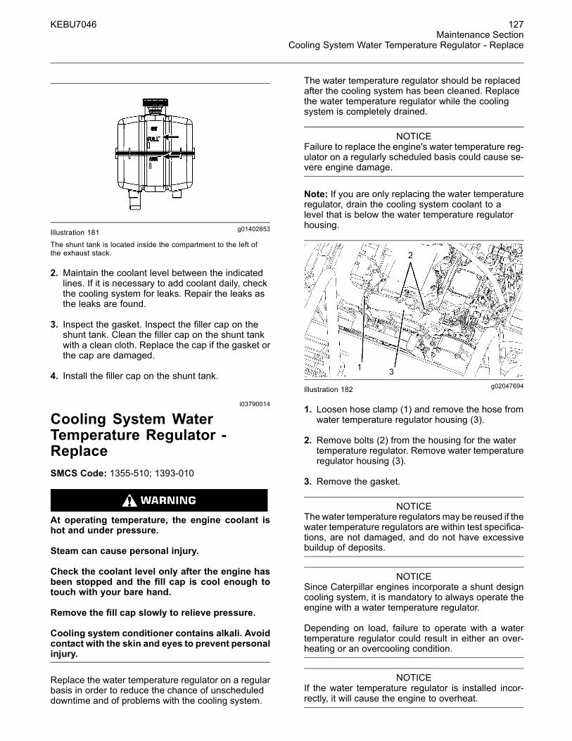
g02047694Illustration 182
1. Loosen hose clamp (1) and remove the hose fromwater temperature regulator housing (3).
2. Remove bolts (2) from the housing for the watertemperature regulator. Remove water temperatureregulator housing (3).
3. Remove the gasket.
NOTICEThewater temperature regulators may be reused if thewater temperature regulators are within test specifica-tions, are not damaged, and do not have excessivebuildup of deposits.
NOTICESince Caterpillar engines incorporate a shunt designcooling system, it is mandatory to always operate theengine with a water temperature regulator.
Depending on load, failure to operate with a watertemperature regulator could result in either an over-heating or an overcooling condition.
NOTICEIf the water temperature regulator is installed incor-rectly, it will cause the engine to overheat.

128 KEBU7046Maintenance SectionDrag Conveyors - Adjust
4. Install a new water temperature regulator and anew gasket.
5. Install the hose. Tighten the hose clamp (1).
6. Inspect pressure cap and the gasket for damage.Replace the pressure cap if the pressure cap orthe gasket are damaged.
7. Install the water temperature regulator housing(3). Install the two bolts (2).
8. Add the cooling system coolant. Maintain thecoolant level to the top of the filler tube.
9. Close all access doors and lock the access doors.
i03790052
Drag Conveyors - AdjustSMCS Code: 6630-025
g01358509Illustration 183(1) Drag conveyor(2) Supports(3) Roller(4) Side Plate(5) Conveyor's Support
In order to adjust the drag conveyor (1) to theproper tension, use the side plate (4) as a reference.The drag conveyor (1) should hang approximately1.27 cm (0.5 inch) above the edge of the side plate(4). There are two supports (5) along the length of thedrag conveyor. Perform the following steps in orderto tighten or loosen the drag conveyor.
g02047733Illustration 184(6) Adjusting rod(7) Cotter pin(8) Front takeup shaft
1. Remove cotter pin (7) from adjusting rod (6).
2. Remove adjusting rod from front takeup shaft (6).
3. Insert the adjusting rod (6) into the holes of fronttakeup shaft (8) in order to adjust the drag chain.Adjust the front takeup shaft in small increments.Turn the front takeup shaft counterclockwise inorder to tighten the drag chain. Turn the fronttakeup shaft clockwise in order to loosen the dragchain.
4. Check drag chain for the correct chain tensionafter each adjustment.
5. Place the adjusting rod in the front takeup shaft.Place cotter pin (7) in adjusting rod (6).
i03790114
Drag Conveyors - LubricateSMCS Code: 6630-086
NOTICEAll daily grease lubricant should be applied at the endof each machine operation while the machine is stillwarm and the asphalt is still soft or not set up. Failureto do so may allow asphalt to harden around the sealsand risk damaging a seal and lead to premature bear-ing failure.

KEBU7046 129Maintenance Section
Engine Air Cleaner Inlet - Clean
g02047799Illustration 185
Lubricate the four grease fittings on the front rightside of the machine. This will provide grease to therear bearings. When you use a standard grease gun,pump 15 pumps per fitting. The grease should purgethe bearings.
g02047800Illustration 186
The grease points are located behind the right access door.
Lubricate the four grease fittings on the rear rightside of the machine. This will provide grease to therear bearings. When you use a standard grease gun,pump 15 pumps per fitting. The grease should purgethe bearings.
i03790145
Engine Air Cleaner Inlet - CleanSMCS Code: 1051-070-IL
The engine air inlet is located in the left side enginecompartment. Check the engine air inlet for anydebris or obstructions.
g02047855Illustration 187
i00058639
Engine Air Filter PrimaryElement - Clean/ReplaceSMCS Code: 1054-070-PY; 1054-510-PY
NOTICEDo not clean the filter elements by bumping or tappingthem. Do not use filter elements with damaged pleats,gaskets or seals. Engine damage can result.
Make sure the cleaned filter elements are completelydry before installing into the filter housing. Water re-maining in the elements can cause false indicationsof contamination in Scheduled Oil Sampling test re-sults.
The filter elements can be cleaned by using thefollowing methods:
• pressure air
• pressure water
• detergent washing
When you use pressure air, the maximum airpressure is 205 kPa (30 psi). When you use pressurewater, the maximum water pressure is 280 kPa(40 psi).

130 KEBU7046Maintenance SectionEngine Air Filter Secondary Element - Replace
g00038608Illustration 188
1. When you clean the inside pleats and the outsidepleats, direct the air along the pleats or direct thewater along the pleats.
The element can be washed in a solution thatconsists of warm water and of nonsudsinghousehold detergent. Fully rinse the pleats. Allowthe filter to air dry completely.
2. Inspect the filter elements after you clean the filterelements. Do not use a filter if the pleats, thegaskets or the seals are damaged.
3. Cover the clean filter elements. Store the elementsin a clean, dry location.
Replace the primary element after the primaryelement has been cleaned six times. Also replacethe primary element if the primary element hasbeen in service for one year.
i03631053
Engine Air Filter SecondaryElement - ReplaceSMCS Code: 1054-510-SE
NOTICEAlways replace the secondary filter element. Never at-tempt to reuse the secondary filter element by clean-ing the element.
When the primary filter element is replaced, the sec-ondary filter element should be replaced.
The secondary filter element should also be replacedif the exhaust smoke is still black.
1. Open the engine compartment.
2. See Operation and Maintenance Manual, “EngineAir Filter Primary Element - Clean/Replace”.Remove the air cleaner cover from the air cleanerhousing. Remove the primary filter element fromthe air cleaner housing.
g00101451Illustration 189
3. Remove the secondary filter element.
4. Cover the air inlet opening. Clean the inside ofthe air cleaner housing.
5. Remove the cover from the air inlet opening.
6. Install the new secondary filter element.
7. Install the primary filter element.
8. Install the air cleaner cover and close the latchessecurely.
9. Close the engine compartment.
i03790189
Engine Air Filter ServiceIndicator - InspectSMCS Code: 7452-040
1. Start the engine.
2. Run the engine at high idle.

KEBU7046 131Maintenance Section
Engine Crankcase Breather - Clean
g02047893Illustration 190
3. If the yellow piston in the engine air filter serviceindicator enters the red zone, service the aircleaner.
4. Stop the engine.
Note: See the Operation and Maintenance Manual,“Engine Air Filter Primary Element - Clean/Replace”.See the Operation and Maintenance Manual, “EngineAir Filter Secondary Element - Replace”.
i03790243
Engine Crankcase Breather -CleanSMCS Code: 1317-070
g02047914Illustration 191
1. Remove the crankcase breather and the O-ringseal.
2. Wash the breather in clean, nonflammable solvent.Use pressure air in order to dry the element.
3. Check the O-ring seal for damage. Replace theO-ring seal if the O-ring seal is damaged. Installthe O-ring seal.
4. Install the crankcase breather.
i03790333
Engine Mounts - InspectSMCS Code: 1152-040
g02048014Illustration 192
There are four engine mounts. Be sure to inspecteach mount.
Inspect the engine mounts for deterioration.
Inspect the engine mounts for correct bolt torque.
Engine vibration can be caused by improper mountingof the engine. Engine vibration can be caused byloose engine mounts or deteriorated engine mounts.
Replace any engine mount that is deteriorated.
If the mounts are loose, torque the front enginemounts and the rear engine mounts to 460 ± 60 N·m(340 ± 40 lb ft).
i03792150
Engine Oil Level - CheckSMCS Code: 1000-535-FLV
1. To check the oil level, stop the engine.

132 KEBU7046Maintenance SectionEngine Oil Sample - Obtain
g02049453Illustration 193
2. Check the engine oil level with oil level gauge (2).
NOTICEDo not overfill crankcase. The oil level must not beabove the FULL RANGE on the dipstick.
3. Maintain the engine oil level on the oil level gaugebetween the “FULL” mark and the “ADD” mark .
4. Clean oil filler cap (1). Remove the oil filler cap. Ifnecessary, add oil.
5. Install the oil filler cap (1).
i03792193
Engine Oil Sample - ObtainSMCS Code: 1000-008; 7542-008
Hot oil and hot components can cause personalinjury. Do not allow hot oil or hot components tocontact the skin.
g02049513Illustration 194
Remove the rear access cover in order to gainaccess to oil sample port (1).
Refer to Special Publication, SEBU6250, “S·O·S OilAnalysis” for information that pertains to obtaining asample of the engine oil. Refer to Special Publication,PEHP6001, “How To Take A Good Oil Sample” formore information about obtaining a sample of theengine oil.
i03792283
Engine Oil and Filter - ChangeSMCS Code: 1318-510
g02049615Illustration 195
1. Remove drain hose (1) from the retainer.
2. Remove the cap from the end of drain hose (1).Drain the oil into a suitable container.
Note: Refer to Operation and Maintenance Manual,“General Hazard Information” for more information oncontaining fluid spillage.
g02049616Illustration 196
3. Remove the rear access cover in order to gainaccess to filter (2). Remove filter (2). Discard theused filter element.

KEBU7046 133Maintenance Section
Engine Valve Lash - Check
4. Clean the filter housing base. All of the old filterseal must be removed from the filter housing base.
5. Apply a thin coat of engine oil to the seal of thenew filter element.
6. Install the new filter by hand.
Instructions for the installation of the filter areprinted on the side of each Caterpillar spin-onfilter. For non-Caterpillar filters, refer to theinstallation instructions that are provided by thesupplier of the filter.
7. Install the access cover for the oil filter.
g02049619Illustration 197
8. Remove oil filler cap (3). Fill the crankcase withnew oil. See Operation and Maintenance Manual,“ Capacities (Refill)” for the correct refill capacity.Clean the oil filler cap and install the oil filler cap.
9. Check the engine oil level with oil level gauge (4).Maintain the oil level between the “FULL” markand the “ADD” mark on the oil level gauge.
10.Start the engine and run the engine for twominutes. Monitor the oil pressure gauge.
11. Inspect the machine for oil leaks.
12.Stop the engine.
13.Wait for ten minutes in order to allow the oil todrain back into the crankcase. Check the oil level.
i01633611
Engine Valve Lash - CheckSMCS Code: 1105-535
This maintenance is recommended by Caterpillaras part of a lubrication and preventive maintenanceschedule in order to help provide maximum enginelife.
NOTICEOnly qualified service personnel should perform thismaintenance. Refer to the Service Manual or yourCaterpillar dealer for the complete valve lash adjust-ment procedure.
Operation of Caterpillar engines with improper valveadjustments can reduce engine efficiency. This re-duced efficiency could result in excessive fuel usageand/or shortened engine component life.
i03792710
Final Drive Planetary Oil -ChangeSMCS Code: 4050-044-OC
The final drive planetary is located at the rear of thetrack assembly. There are two final drives. One finaldrive is on each side of the machine.
Perform this procedure for the final drive planetary onboth sides of the machine.
g02049973Illustration 198
Note: The final drive planetary has three plugs.Position the final drive with plug (1) at the top of thedrive.
1. Remove drain plug (3) and allow the oil to draininto a suitable container.
2. Clean plug (3) and install the plug.
3. Remove plug (1). Fill the final drive planetary.Allow the machine to sit for 45 minutes.
Reference: Refer to Operation and MaintenanceManual, “Capacities (Refill)” for the correct refillcapacity.

134 KEBU7046Maintenance SectionFinal Drive Planetary Oil Level - Check
Note: The machine needs to sit for 45 minutesin order to fill the rear bearings of the final driveplanetary. Failure to wait for 45 minutes may result inbearing failure.
4. Fill the planetary with oil up to plug (2).
5. Clean plug (1) and install the plug.
i03792775
Final Drive Planetary Oil Level- CheckSMCS Code: 4050-535-FLV
g02050075Illustration 199
The final drive planetary is located at the rear of eachtrack assembly. There is one final drive on each sideof the machine.
Check the oil level of each drive.
Note: The final drives have three plugs. Position thefinal drive with plug (1) at the top of the drive. Plug(2) is used to check the level of the oil in the drive.
Remove the oil level check plug (2). The oil levelshould be at the bottom of the opening for the oillevel check plug.
Remove plug (1) in order to fill the drive. Clean theplugs and install the plugs.
i03792779
Final Drive Planetary OilSample - ObtainSMCS Code: 4050-008; 7542-008
g02050079Illustration 200
Refer to Special Publication, SEBU6250, “S·O·S OilAnalysis” for information that pertains to obtaininga sample of oil. Refer to Special Publication,PEHP6001, “How To Take A Good Oil Sample” formore information about obtaining a sample of oil.
i03793550
Fuel System - PrimeSMCS Code: 1250-548
g02050776Illustration 201
1. Operate the fuel priming pump in order to fillthe new filter element with fuel. Push the switchdownward in order to activate the fuel primingpump. Hold the switch downward for a fewseconds.
Note: The fuel priming pump will only function withthe engine start switch in the OFF position.

KEBU7046 135Maintenance Section
Fuel System Filter (Washdown) - Clean
2. Start the engine. If the engine will not start, furtherpriming is necessary. If the engine starts but theengine continues to misfire, further priming isnecessary. If the engine starts but the enginecontinues to emit smoke, further priming isnecessary.
3. If the engine starts but the engine runs rough,continue to run the engine at low idle. Continueto run the engine at low idle until the engine runssmoothly.
i03797869
Fuel System Filter (Washdown)- CleanSMCS Code: 1261-070; 5642-070-FI
Fuel leaked or spilled onto hot surfaces or elec-trical components can cause a fire. To help pre-vent possible injury, turn the start switch off whenchanging fuel filters or water separator elements.Clean up fuel spills immediately.
NOTICEDo not allow dirt to enter the fuel system. Thoroughlyclean the area around a fuel system component thatwill be disconnected. Fit a suitable cover over discon-nected fuel system component.
g02054373Illustration 202
1. Place a container under the fuel filter (1) beforeyou remove the filter.
Note: Refer to Operation and Maintenance Manual,“General Hazard Information” for information oncontaining fluid spillage.
2. Remove the fuel filter (1).
3. Clean the filter of any debris.
4. Reinstall the filter.
i03793599
Fuel System Primary Filter -Clean/Inspect/ReplaceSMCS Code: 1260-510; 1260-571
Fuel leaked or spilled onto hot surfaces or elec-trical components can cause a fire. To help pre-vent possible injury, turn the start switch off whenchanging fuel filters or water separator elements.Clean up fuel spills immediately.
NOTICEDo not allow dirt to enter the fuel system. Thoroughlyclean the area around a fuel system component thatwill be disconnected. Fit a suitable cover over discon-nected fuel system component.
NOTICEDo not use a tool in order to remove the fuel filter.Attempting to remove the fuel filter with a filter wrenchor a filter strap could damage the locking ring.
g02050833Illustration 203
1. Place a tray under fuel filter (1) in order to catchany fuel that might spill. Clean up any spilled fuelimmediately.

136 KEBU7046Maintenance SectionFuel System Secondary Filter - Replace
NOTICECare must be taken to ensure that fluids are containedduring performance of inspection, maintenance, test-ing, adjusting and repair of the product. Be prepared tocollect the fluid with suitable containers before open-ing any compartment or disassembling any compo-nent containing fluids.
Refer to Special Publication, NENG2500, “CaterpillarDealer Service Tool Catalog” for tools and suppliessuitable to collect and contain fluids on Caterpillarproducts.
Dispose of all fluids according to local regulations andmandates.
2. Clean the outside of fuel filter assembly. Open thedrain (4) on the bottom of the fuel filter. Drain thefuel and the water from the element into a suitablecontainer.
3. Hold the element and rotate the locking ring (2)counterclockwise. Remove the locking ring (2).The used filter element should be removed anddiscarded.
4. Remove the sediment bowl (3) from the element.
5. Thoroughly clean the sediment bowl (3). Inspectthe O-ring seals. Install new O-ring seals, ifnecessary.
6. Install the sediment bowl to the new element.Hand tighten the sediment bowl.
Note: Hand tightening is the only method that shouldbe used.
NOTICEDo not fill fuel filters with fuel before installing them.Contaminated fuel will cause accelerated wear to fuelsystem parts.
7. Ensure that the filter head is clean. Push a newelement fully into the filter head.
8. Hold the element in place. Fit the locking ring (2)into position. Rotate the locking ring clockwise inorder to fasten the element to the filter head.
Note: If the nylon insert was removed, install thenylon insert and install the cap.
9. Prime the fuel system. Refer to the Operation andMaintenance Manual, “Fuel System - Prime” in theMaintenance Section for more information.
i03793612
Fuel System Secondary Filter -ReplaceSMCS Code: 1261-510-SE
Fuel leaked or spilled onto hot surfaces or elec-trical components can cause a fire. To help pre-vent possible injury, turn the start switch off whenchanging fuel filters or water separator elements.Clean up fuel spills immediately.
NOTICECare must be taken to ensure that fluids are containedduring performance of inspection, maintenance, test-ing, adjusting and repair of the product. Be prepared tocollect the fluid with suitable containers before open-ing any compartment or disassembling any compo-nent containing fluids.
Refer to Special Publication, NENG2500, “CaterpillarDealer Service Tool Catalog” for tools and suppliessuitable to collect and contain fluids on Caterpillarproducts.
Dispose of all fluids according to local regulations andmandates.
g02050876Illustration 204
1. Open the engine hood in order to access the fuelsystem's secondary fuel filter.
2. Remove the filter. Discard the filter properly.
3. Clean the mounting base of the fuel filter. Removeany part of the old seal that remains on themounting base of the fuel filter.
4. Install the new filter by hand. When the sealcontacts the base, tighten the fuel filter elementby an additional 3/4 turn.

KEBU7046 137Maintenance Section
Fuel System Third Filter - Replace
Note: Rotational index marks are positioned on thefilter at 90 degree intervals. Use these rotation indexmarks as a guide when you tighten the filter.
5. Clean up any spills immediately.
6. Start the engine and check for leaks.
i03799292
Fuel System Third Filter -ReplaceSMCS Code: 1261-510; 1261-510-SE
Personal injury or death may result from failure toadhere to the following procedures.
Fuel leaked or spilled onto hot surfaces or electri-cal components can cause a fire.
Clean up all leaked or spilled fuel. Do not smokewhile working on the fuel system.
Turn the disconnect switch OFF or disconnect thebattery when changing fuel filters.
NOTICEDo not fill the fuel filters with fuel before installing thefuel filters. The fuel will not be filtered and could becontaminated. Contaminated fuel will cause acceler-ated wear to fuel system parts.
1. Open the access panel on the right side of themachine.
Note: Refer to Operation and Maintenance Manual,“General Hazard Information” for information oncontaining fluid spillage.
g02055835Illustration 205
2. Remove the filter.
Note: Always discard used filters according to localregulations.
3. Clean the filter mounting base. Make sure that allof the used seal is removed.
4. Coat the seal of the new filter with clean dieselfuel.
5. Install the new fuel filter by hand.
Instructions for the installation of the filter areprinted on the side of each Caterpillar spin-onfilter. For non-Caterpillar filters, refer to theinstallation instructions that are provided by thesupplier of the filter.
6. Prime the fuel system. See Operation andMaintenance Manual, “Fuel System - Prime” forinstructions.
7. Close the engine hood.
i03793628
Fuel System Water Separator- DrainSMCS Code: 1263-543
NOTICECare must be taken to ensure that fluids are containedduring performance of inspection, maintenance, test-ing, adjusting and repair of the product. Be prepared tocollect the fluid with suitable containers before open-ing any compartment or disassembling any compo-nent containing fluids.
Refer to Special Publication, NENG2500, “CaterpillarDealer Service Tool Catalog” for tools and suppliessuitable to collect and contain fluids on Caterpillarproducts.
Dispose of all fluids according to local regulations andmandates.

138 KEBU7046Maintenance SectionFuel Tank Cap, Filter, and Strainer - Clean/Inspect/Replace
g02050914Illustration 206
1. Open drain (2) on water separator bowl (1).
2. Drain the water from water separator bowl (1) intoa suitable container. Close drain (2).
i03793681
Fuel Tank Cap,Filter, and Strainer -Clean/Inspect/ReplaceSMCS Code: 1273-070-STR; 1273-070-Z2
g02050935Illustration 207
1. Remove the cap and the strainer.
2. Wash the cap and the strainer in cleannonflammable solvent.
3. Allow the filter inside the cap to dry, or usepressure air in order to dry the filter.
4. Install the strainer and the tank cap.
i03793710
Fuel Tank Water and Sediment- DrainSMCS Code: 1273-543-M&S
g02050974Illustration 208
1. The drain hose for the fuel tank is located in theleft side access door.
2. Remove the plug from the drain hose.
3. Drain the water and sediment from the fuel tankinto a suitable container.
Note: Refer to Operation and Maintenance Manual,“General Hazard Information” for information oncontaining fluid spillage.
4. Replace the plug for the drain hose.
i03841549
Fuses - ReplaceSMCS Code: 1417-510
Fuse – The fuses protect the electricalsystem from damage that is caused byoverloaded circuits. Change the fuse if the
element separates. If the element of the new fuseseparates, check the circuit. Repair the problembefore you operate the machine.
NOTICEReplace the fuses with the same type and size only.Otherwise, electrical damage can result.
If it is necessary to replace fuses frequently, an elec-trical problem exists. Contact your Caterpillar dealer.

KEBU7046 139Maintenance Section
Fuses - Replace
Primary Fuse PanelThe primary fuse panel is located behind the accesspanel below the exhaust stack.
g02089556Illustration 209
Table 15
Primary Fuse Panel
1 2 3 4 5
A Brake Lights15A
Spare Switched15A
Machine ECM15A
Autolube15A
Brake LightsRelay
B Glow Plugs20A
Operator Control15A
Parking Lights20A
Spare Unswitched15A
Left Turn SignalRelay
C Screed25A
HID Lights25A
Work Lights20A
Right Turn SignalRelay
D Limp Home Mode10A
Travel Lights20A
12 V Power Supply15A
Parking LightsRelay
E Generator15A
Slave ECM15A
Spray Down15A
Travel LightsRelay
F Sensor10A
Display10A
Screed ECM15A
Spray DownRelay
G Grade Slope15A
Horn10A
Operator ECM15A
Work LightsRelay

140 KEBU7046Maintenance SectionGenerator - Clean
Secondary Fuse PanelThe secondary fuse panel is located behind the leftside access door.
g02089557Illustration 210
Table 16
Secondary Fuse Panel
A Starter Relay Fuse60A
B Starter Motor Fuse30A
C Main Power Relay Fuse30A
D Main Power Fuse40A
E Glow Plug Relay Fuse50A
F Glow Plug Fuse30A
Note: Spare relays are located behind the fuse panel.
i03857932
Generator - CleanSMCS Code: 4450-070
Personal injury or death can result from high volt-age.
When power generation equipment must be in op-eration to make tests and/or adjustments, highvoltage and current are present.
Improper test equipment can fail and present ahigh voltage shock hazard to its user.
Make sure the testing equipment is designed forand correctly operated for high voltage and cur-rent tests being made.
When servicing or repairing electric power gener-ation equipment:
• Make sure the unit is off-line (disconnectedfrom utility and/or other generators powerservice) , and either locked out or tagged DONOT OPERATE.
• Remove all fuses.
• Make sure the generator engine is stopped.
• Make sure all batteries are disconnected.
• Make sure all capacitors are discharged.
Failure to do so could result in personal injury ordeath. Make sure residual voltage in the rotor, sta-tor and the generator is discharged.
When the engine-generator is operating, voltagesup to 600V are present in these areas near or onthe regulator:
a. the regulator terminal strip
b. the excitation transformer terminal strip (self-excited generator only)
NOTICEElectronic components in the regulator can be dam-aged during generator operation if contact is made be-tween the part and ground.

KEBU7046 141Maintenance SectionGround Fault - Check
g02102139Illustration 211
Remove the top cover of the generator in order toclean the generator.
Periodically, generators should be inspected forcleanliness. The following contaminants should notbe allowed to accumulate on the windings:
• dirt
• dust
• grease
• salt
• oil film
If moisture is allowed to remain in contact withan electrical winding, some of the moisture willeventually be retained in voids or cracks of theinsulation. This will lower the resistance of thewinding insulation. The insulation that is used onthe windings of Caterpillar generators is moistureresistant. However, constant exposure to moisturewill gradually lower the insulation's resistance.
Dirt can make the problem worse. Dirt can holdmoisture in contact with the insulation. The salt thatis present in sea air can compound the problem.When salt and moisture combine, a good electricalconductor is created.
Clean the voltage regulator and clean the generator ofdirt and debris. Use a brush to loosen accumulationsof dirt. Vacuum clean the system in order to removeresidual dirt. The use of compressed air is notrecommended. Compressed air contains moisturethat is present in the form of condensation.
Carbon tracking on insulators can be caused bydirt or carbon tracking on insulators can be causedby loose connections. These carbon paths must becleaned or the insulators must be replaced. A failureto correct a carbon tracking problem will result in anelectrical short in the circuit.
Visually check for loose wires or broken wires.Also, visually check for loose connections or brokenconnections. Check the wires and connections onthe voltage regulator assembly. Check all wires andconnections in the generator. Clean heat sinks. Makeany necessary repairs to the wiring.
Refer to Special Instruction, SEHS9124, “Cleaningand Drying of the Generator” for more information.
i03846449
Ground Fault - Check(If Equipped)SMCS Code: 4450-535; 4461-535
Auxiliary Power Distribution
g02092914Illustration 212
g02092916Illustration 213
1. Press the test buttons (1) that are located on theoutlets. The reset button, which is located next tothe test button, should instantly pop out.
Note: If the reset button does not pop out, the outletneeds to be replaced.
2. Press the reset button in order to reset the outlet.

142 KEBU7046Maintenance SectionHopper Cylinder Bearings - Lubricate
3. Press test buttons (2) that are located on thecircuit breakers. The reset button, which is locatednext to the test button, should instantly pop out.
Note: If the reset button does not pop out, the circuitbreaker needs to be replaced.
4. Press the reset button in order to reset the circuitbreaker.
Work Tool Mode
g02092913Illustration 214
You should only operate work tools from themachine's auxiliary power source when switch (3)is in the ON position. Press switch (3) upward inorder to turn on the work tool mode. Press switch (3)downward in order to turn off the work tool mode.
Generator
g02092253Illustration 215
1. Press the test button (4) that is located on thecircuit breaker. The reset button, which is locatednext to the test button should instantly pop out.
Note: If the reset button does not pop out, the circuitbreaker needs to be replaced.
2. Press the reset button in order to reset the circuitbreaker.
3. Repeat the above steps for all four circuit breakersthat are located on the generator.
i03793781
Hopper Cylinder Bearings -LubricateSMCS Code: 5102-086-BD
g02051033Illustration 216
Left Hopper Cylinder
There are two grease fittings on each hopper cylinder.There is a fitting at the top of the cylinder. There is afitting at the bottom of the cylinder.
There are two cylinders on the machine. One cylinderis on each side of the machine.
The top grease fitting for each cylinder can beaccessed through the radiator access cover. Thelower grease fittings can be accessed through theside access doors.

KEBU7046 143Maintenance Section
Hopper Flashing - Inspect/Replace
i03356040
Hopper Flashing -Inspect/ReplaceSMCS Code: 6639-040-FK; 6639-510-FK
g01730235Illustration 217
Inspect the front hopper flashing for deterioration.Hot asphalt and trucks that are delivering the asphaltto the machine can damage the hopper flashing.If necessary, repair the hopper flashing. Hopperflashing that is not repaired or replaced can causeexcess spillage of asphalt in front of the machine.
i03793826
Hydraulic System Oil Level -CheckSMCS Code: 5056-535-FLV
g02051094Illustration 218
1. Check the hydraulic oil level with oil level gauge(1).
2. Maintain the oil level between the “FULL” markand the “ADD” mark.
3. Add additional oil if the oil level is below the “ADD”mark.
4. Check filler cap (2). Replace the filler cap if thefiller cap is damaged.
5. Install the filler cap (2).
i03793862
Hydraulic System Oil andFilters - ChangeSMCS Code: 5056-044; 5068-510
g02051154Illustration 219
(1) Charge Filter(2) Return Filter Indicator(3) Hydraulic Tank Cap(4) Hydraulic Oil Level Gauge(5) Return Filter
1. Remove hydraulic tank cap (3) in order to relievepressure from the hydraulic system.
g02051167Illustration 220
2. Remove drain plug (6) and install the 134-8474drain hose. Drain the hydraulic oil into a suitablecontainer.
Note: Refer to Operation and Maintenance Manual,“General Hazard Information” for information oncontaining fluid spillage.

144 KEBU7046Maintenance SectionHydraulic System Oil Sample - Obtain
3. Remove the cover for the charge filter (1). Removethe charge filter.
4. Remove the return filter cover (5). Remove thereturn filter.
5. Remove the drain hose and Install drain plug (6).
6. Install a new charge filter. Install the cover for thecharge filter (1).
7. Install a new return filter. Install the return filtercover (5).
8. Fill the hydraulic tank. Refer to the Operation andMaintenance Manual, “Capacities (Refill)” for thecorrect refill capacity.
9. Replace hydraulic tank cap (3).
10.Start the engine. Run the engine for a fewminutes. Check the hydraulic filters for leaks.
11.Stop the engine.
12.Repair the leaks that were found.
13.Maintain the oil between the “FULL” and “ADD”marks on oil level gauge (4).
i03793958
Hydraulic System Oil Sample- ObtainSMCS Code: 5050-008; 7542-008
g02051235Illustration 221
Refer to Special Publication, SEBU6250, “S·O·S OilAnalysis” for information that pertains to obtaininga sample of the hydraulic oil. Refer to SpecialPublication, PEHP6001, “How To Take A Good OilSample” for more information about obtaining asample of the hydraulic oil.
i02747547
Idler Bearings (Takeup) -LubricateSMCS Code: 4159-086-BD
g01376247Illustration 222
There are two idlers on each side of the track. Thereis a fitting in the middle of each of the four idlers.
Apply grease to the four idlers. Apply grease untilexcess grease is observed from the grease relieffitting on the inside part of the idler hub.
i02747558
Idler Wheel (Takeup) - InspectSMCS Code: 4159
g01376253Illustration 223
Check idler rims and track roller rims for damage.Notify your dealer if damaged rims are observed.Damaged rims may cause damage to the track.Damaged rims may cause improper track movement.

KEBU7046 145Maintenance SectionOil Filter - Inspect
i02106227
Oil Filter - InspectSMCS Code: 1308-507; 3004-507; 5068-507
Inspect a Used Filter for Debris
g00100013Illustration 224
The element is shown with debris.
Use a filter cutter to cut the filter element open.Spread apart the pleats and inspect the element formetal and for other debris. An excessive amount ofdebris in the filter element can indicate a possiblefailure.
If metals are found in the filter element, a magnet canbe used to differentiate between ferrous metals andnonferrous metals.
Ferrous metals can indicate wear on steel parts andon cast iron parts.
Nonferrous metals can indicate wear on thealuminum parts of the engine such as main bearings,rod bearings, or turbocharger bearings.
Small amounts of debris may be found in the filterelement. This could be caused by friction and bynormal wear. Consult your Caterpillar dealer in orderto arrange for further analysis if an excessive amountof debris is found.
Using an oil filter element that is not recommendedby Caterpillar can result in severe engine damageto engine bearings, to the crankshaft, and to otherparts. This can result in larger particles in unfilteredoil. The particles could enter the lubricating systemand the particles could cause damage.
i03798732
Pump Drive Breather - CleanSMCS Code: 3108-070-BRE
g02055053Illustration 225
1. Remove the breather from the gearbox.
2. Wash the breather in clean nonflammable solvent.
3. Allow the breather to dry, or use pressure air inorder to dry the breather.
4. Install the breather.
i03798751
Pump Drive Oil - ChangeSMCS Code: 3108-044-OC
g02055056Illustration 226
1. Remove the cap from the drain hose (1). Allow theoil to drain into a suitable container.
Note: Refer to Operation and Maintenance Manual,“General Hazard Information” for information oncontaining fluid spillage.
2. Clean the cap for the drain hose. Install the capon the drain hose.

146 KEBU7046Maintenance SectionPump Drive Oil Level - Check
3. Dispose of the oil in a proper manner.
g02055061Illustration 227
g02055059Illustration 228
4. Remove plug (3) in order to fill the pump drive withoil. Remove the breather (2). See the Operationand Maintenance Manual, “Pump Drive Breather -Clean” for cleaning instructions.
5. Fill the gearbox. See the Operation andMaintenance Manual, “Capacities (Refill) ” for theamount of oil that is needed in order to fill thegearbox.
g02055760Illustration 229
g02111616Illustration 230
6. Check the oil level with oil level gauge (4). The oillevel can also be viewed through sight gauge (5)on the pump drive which can be seen through theaccess doors in the hopper.
7. Maintain the pump drive oil level on oil level gauge(4) between the “FULL” mark and the “ADD” mark.
8. Clean the breather and install the breather (2).
9. Clean the plug and install the plug (3).
i03799255
Pump Drive Oil Level - CheckSMCS Code: 3108-535-FLV
NOTICECaterpillar recommends obtaining an oil sample andperforming a SOS Oil Analysis at regular intervals tohelp prevent damage to components. Use the infor-mation in "Sampling Interval and Location of the Sam-pling Valve" in this OMM to find the proper samplinginterval for your machine.
g02055773Illustration 231

KEBU7046 147Maintenance Section
Pump Drive Oil Sample - Obtain
g02111609Illustration 232
1. Check the oil level with oil level gauge (1). The oillevel can also be viewed through sight gauge (2)on the pump drive which can be seen through theaccess doors in the hopper.
Note:
2. Maintain the pump drive oil level on oil level gauge(1) between the “FULL” mark and the “ADD” mark .
g02055793Illustration 233
3. If oil needs to be added, remove the plug (3) forthe fill port. Add oil through the opening.
4. Clean the plug (3) and install the plug (3).
i03799270
Pump Drive Oil Sample -ObtainSMCS Code: 3108-008; 7542-008
g02055056Illustration 234
1. Clean the end of drain hose (1) and the cap.Remove the cap from the drain hose. Drain asmall amount of oil into a suitable container.
2. Obtain a sample of the oil in a suitable container.
3. Send the oil sample to your dealer for analysis.
4. Check the level of the oil in the gearbox. Ifnecessary, add oil.
i03625928
Radiator Core - CleanSMCS Code: 1353-070-KO
Make sure that the engine shutdown switch is in theOFF position. Do not clean the radiator core whenthe machine is running.
g00101939Illustration 235

148 KEBU7046Maintenance SectionSeat Belt - Inspect
Inspect the radiator core for debris. If necessary,clean the radiator.
Compressed air is preferred, but high pressure wateror steam can be used to remove dust and generaldebris from a radiator. Clean the radiator accordingto the condition of the radiator.
See Special Publication, SEBD0518, “Know YourCooling System” for more detailed information aboutcleaning radiator fins.
i02429589
Seat Belt - InspectSMCS Code: 7327-040; 7327; 7520
Always check the condition of the seat belt and thecondition of the seat belt mounting hardware beforeyou operate the machine. Replace any parts that aredamaged or worn before you operate the machine.
g00932801Illustration 236
Typical example
Check the seat belt mounting hardware (1) for wearor for damage. Replace any mounting hardware thatis worn or damaged. Make sure that the mountingbolts are tight.
Check buckle (2) for wear or for damage. If the buckleis worn or damaged, replace the seat belt.
Inspect the seat belt (3) for webbing that is worn orfrayed. Replace the seat belt if the seat belt is wornor frayed.
Consult your Caterpillar dealer for the replacement ofthe seat belt and the mounting hardware.
Note:Within three years of the date of installation orwithin five years of the date of manufacture, replacethe seat belt. Replace the seat belt at the date whichoccurs first. A date label for determining the age ofthe seat belt is attached to the seat belt, the seat beltbuckle, and the seat belt retractor.
If your machine is equipped with a seat beltextension, also perform this inspection procedure forthe seat belt extension.
i02429594
Seat Belt - ReplaceSMCS Code: 7327-510
Within three years of the date of installation or withinfive years of the date of manufacture, replace theseat belt . Replace the seat belt at the date whichoccurs first. A date label for determining the age ofthe seat belt is attached to the seat belt, the seat beltbuckle, and the seat belt retractor.
g01152685Illustration 237(1) Date of installation (retractor)(2) Date of installation (buckle)(3) Date of manufacture (tag) (fully extended web)(4) Date of manufacture (underside) (buckle)
Consult your Caterpillar dealer for the replacement ofthe seat belt and the mounting hardware.
If your machine is equipped with a seat beltextension, also perform this replacement procedurefor the seat belt extension.
i00684312
Starting Motor - InspectSMCS Code: 1453-040
A scheduled inspection of the starting motor isrecommended. If the starting motor fails, the enginemay not start.
Check the starting motor for proper operation. Checkthe electrical connections and clean the electricalconnections. Refer to the Service Manual for moreinformation on the checking procedure and forspecifications or consult your dealer for assistance.

KEBU7046 149Maintenance Section
Toggle Switch - Inspect
i02711091
Toggle Switch - InspectSMCS Code: 7332-040
g01360853Illustration 238(1) Switch in neutral position(2) Displaced switch(3) Seal
Perform the following steps in order to inspect theswitches on your machine.
1. Turn the engine start switch to the OFF position.Do not test the switches when the machine isrunning.
2. Visually inspect the area around the seal (3). Lookfor cracks or splits on the seal. If any cracks orsplits are noticed, replace the switch.
3. Lightly move the toggle switch (1) in order to testfor free play. If the switch moves more than 2 mm(0.01 inch) in either direction, replace the switch.
4. Press the switch upward. The toggle switch (1)should displace approximately 5 mm (0.2 inch). Ifthe switch has an incorrect displacement, replacethe switch. Repeat the measurement when youpress the switch downward.
i03794269
Tow Arm Joint Nuts - TightenSMCS Code: 7121-079-NT
There are four nuts on each tow arm.
g02051473Illustration 239
Torque the nuts to 373 ± 50 N·m (275 ± 37 lb ft). Thereare four nuts on each side of the machine. There area total of eight nuts that need to be tightened.
i03794333
Tracks - InspectSMCS Code: 4170-040
g02051535Illustration 240
Visually inspect the Mobil-Trac System for wear ordamage. If there are cuts or gouges on the track thatcould affect the performance of the machine, replacethe damaged component immediately.
In order to extend the life of the track, periodicallyrotate the belts. When you rotate the belts you betterdistribute the wear. Consult with your Caterpillardealer before you attempt this procedure.

150 KEBU7046Maintenance SectionTrack Roller Bearings - Inspect
i03794328
Track Roller Bearings - InspectSMCS Code: 4180-040-BD
g00863637Illustration 241
There are four rollers on each side of the track.There are a total of eight rollers on each side of themachine. There are a total of sixteen rollers that needto be checked.
Remove the plug on the roller. Inspect the hub for thepresence of oil. Install the plug on the roller.
i03794370
Track Roller Bearings -LubricateSMCS Code: 4180-086-BD
g01380392Illustration 242
There are four rollers on each side of the track.There are a total of eight rollers on each side of themachine. There are a total of sixteen rollers that needto be lubricated.
Remove the plug (1) on the roller. Fill each hub withSAE 30W oil until excess oil is observed. Install theplug on the roller.
Note: The five inboard rollers may be accessed byplacing the machine on supports.
i03797950
Track Roller Frame - LubricateSMCS Code: 4151-086
g02054414Illustration 243
There are three lubrication points on each side of themachine. There are a total of six lubrication points onthe machine. Pump grease into the fittings (1) untilresistance is felt.
i03797975
Track Takeup Linkage -LubricateSMCS Code: 4157-086-KL
g02054454Illustration 244
There are four grease fittings. There are two greasefittings on each set of linkage. There is one set oflinkages on each side of the machine.
Clean the fittings before you lubricate the linkage.
Add the lubricant until a small amount of lubricant isobserved at the linkage.

KEBU7046 151Maintenance SectionTrack Tension - Check
Note: You must remove the plugs and you mustinstall grease fittings in order to lubricate the linkage.
Note: Lubricate the fittings when the track has beenremoved from the machine for service.
i03798029
Track Tension - CheckSMCS Code: 4170-535-T7
g02054495Illustration 245
Note: The track tension system is a closed systemafter the tension has been set. The track has tensionfrom the closed system at all times.
Check the track in order to determine if the track isloose or if the track is tight. If the track is loose, referto the service manual for the correct procedure fortensioning the track.
i03799330
Truck Hitch - Lubricate(If Equipped)SMCS Code: 7122-086
NOTICEAll daily grease lubricant should be applied at the endof each machine operation while the asphalt is stillwarm and not set up. Failure to do so may allow theasphalt to harden around the seals and risk damaginga seal leading to premature bearing failure.
g02055895Illustration 246
There are two roller bearings (1) for the truck hitch.There is one bearing on each side of the truck hitch.Lubricate each bearing.
There are two fittings (2) on the truck hitch system.There is one fitting on each end of the assembly.Lubricate each fitting.
There are two slide assemblies (3) on the truck hitchsystem. There is one slide assembly on each end ofthe assembly. Lubricate each slide assembly.
i03798103
Turbocharger - InspectSMCS Code: 1052-040
g02054554Illustration 247
Periodic inspection and cleaning is recommendedfor the turbocharger compressor housing (inlet side).Since the fumes from the crankcase are filteredthrough the air inlet system, oil and combustionby-products may collect in the turbochargercompressor housing.
Over time, this buildup can contribute to loss ofengine power, increased black smoke and overallloss of engine efficiency. This buildup is only apossible contributor to these factors.

152 KEBU7046Maintenance SectionVentilation Blower Wheel - Inspect/Clean
If the turbocharger fails during engine operation,damage to the turbocharger compressor wheeland/or to the engine may occur. Damage to theturbocharger compressor wheel could allow partsfrom the compressor wheel to enter an enginecylinder. This can cause additional damage to thepistons, the valves, and the cylinder head.
NOTICETurbocharger bearing failures can cause large quan-tities of oil to enter the air inlet and exhaust systems.Loss of engine lubricant can result in serious enginedamage.
Minor leakage of a turbocharger housing under ex-tended low idle operation should not cause problemsas long as a turbocharger bearing failure has not oc-curred.
When a turbocharger bearing failure is accompaniedby a significant engine performance loss (exhaustsmoke or engine rpm up at no load), do not continueengine operation until the turbocharger is repaired orreplaced.
An inspection of the turbocharger can minimizeunscheduled downtime. An inspection of theturbocharger can also reduce the chance for potentialdamage to other engine parts.
Note: Turbocharger components require clearancesthat are very precise. The turbocharger cartridge mustbe balanced due to high rpm. Severe Applicationscan accelerate component wear. Severe Applicationsmay suggest the need to inspect the cartridge atmore frequent intervals.
Removal and InstallationFor options regarding the removal, installation, repairand replacement, consult your dealer. Refer to theService Manual for this engine or consult your dealerfor the procedure and specifications.
Cleaning and Inspecting1. Remove the exhaust outlet piping and removethe air inlet piping from the turbocharger. Visuallyinspect the piping for the presence of oil.
2. Turn the compressor wheel and the turbine wheelby hand. The assembly should turn freely. Inspectthe compressor wheel and the turbine wheel forcontact with the turbocharger housing. Thereshould not be any visible signs of contact betweenthe turbine wheel or compressor wheel and theturbocharger housing. If there is any indicationof contact between the rotating turbine wheelor the turbocharger wheel and the turbochargerhousing, the turbocharger should be reconditionedor replaced.
3. Check the compressor wheel for cleanliness.If only the blade side of the wheel is dirty, dirtand/or moisture is passing through the air filteringsystem. If oil is found only on the back side of thewheel, there is a possibility of a failed turbochargeroil seal.
The presence of oil may be the result of extendedengine operation at low idle. The presence of oilmay also be the result of a restriction of the line forthe inlet air (plugged air filters), which causes theturbocharger to slobber.
4. Clean the turbocharger housing with standardshop solvents and a soft bristle brush.
5. Fasten the air inlet piping and the exhaust outletpiping to the turbocharger housing.
i03862399
Ventilation Blower Wheel -Inspect/CleanSMCS Code: 6654-040-BW; 6654-070-BW
Perform the following steps in order to clean theblower wheel and inspect the blower wheel for theventilation system:
g02105861Illustration 248
1. Remove the four bolts (1) and washers.
2. Remove the exhaust stack.

KEBU7046 153Maintenance Section
Ventilation Blower Wheel - Inspect/Clean
g02105864Illustration 249
g02105866Illustration 250
3. Remove the five bolts (2) and the washers thatare visible in the bottom of the ventilation systemduct after the exhaust stack is removed.
g02105876Illustration 251
4. Open access cover (3).
g02105877Illustration 252
5. Remove the two bolts (4) and the washers.
6. Remove bracket (5).
g02105893Illustration 253
7. Remove the two bolts (6) and washers.
g02105913Illustration 254
8. Remove the hose for the pitot tube from the backof manometer (7).

154 KEBU7046Maintenance SectionVentilation Inlet Ducts - Inspect/Clean
g02105915Illustration 255
9. Open access door (8).
g02105935Illustration 256
10.Remove the two bolts (9) and washers.
11.Remove ventilation duct (10).
g02105953Illustration 257
12. Inspect blower wheel (11) for damage. Clean thewheel with nonflammable solvent. Dry the wheel.Replace the wheel if the wheel is damaged.Inspect the hydraulic motor. If necessary, repairthe motor.
13. Inspect the ducts for the inlet side of the blowerassembly. Clean the ducts with nonflammablesolvent.
14.Reverse steps 1 through 11 in order to reassemblethe ventilation system.
i03798138
Ventilation Inlet Ducts -Inspect/CleanSMCS Code: 6654-040-IL; 6654-070-IL
g02054597Illustration 258
The intake ducts for the ventilation system arelocated at the rear of the machine. The ducts areabove the drag conveyors. There is a duct over eachdrag conveyor. The duct is hinged.
Clean the ducts weekly. Use nonflammable solventin order to clean the ducts.
Dry the ducts before you operate the machine.
g02092093Illustration 259
The manometer on the stack monitors the amountof air that is being discharged. The manometer willshow a minimum of 15 mm (.6 inch) of pressure whenthe ducts are clean.

KEBU7046 155Maintenance Section
Wheel Nuts (Final Drive) - Tighten
Note: If the pressure drops below 15 mm (.6 inch) ofpressure, the ducts may need to be cleaned. If thepressure drops below 15 mm (.6 inch) of pressure,the blower may need to be cleaned.
i01671969
Wheel Nuts (Final Drive) -TightenSMCS Code: 4210-527
g00864096Illustration 260
Nuts (1) may become loose under normal operatingconditions.
Tighten nuts (1) to a torque of 560 ± 60 N·m(413 ± 44 lb ft).


