49
K160 Operators Manual Revision 1, Dated 17 December 2007 1 Keenan K160 Operators Manual This manual applies to machines 16 D 02 onwards
K160 Operators Manual Revision 1, Dated 17 December 2007
1
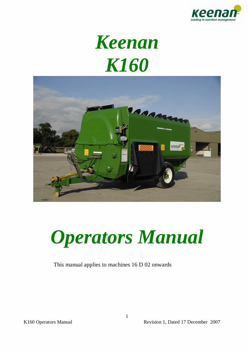
Keenan K160
Operators Manual
This manual applies to machines 16 D 02 onwards
K160 Operators Manual Revision 1, Dated 17 December 2007
2
WARNING NOTES Most sections of the manual apply to both the Keenan Klassik and the Keenan Bale Handler machines. Sections which do not apply to both machines will be clearly stated in the heading and the text. Note: There are 3 different types of notes.
Note: Texts with this heading give general information which improves the operation efficiency of your Keenan K 160.
The Keenan K 160 and the Keenan Bale Handler 16 cubic machines are subject to International patents including the following: European: E0,833,558 USA: 5,967,433 Japan: Pending Canada: Pending Australia: 691418 New Zealand: 305943 South Africa: 96/3148
WARNING: Read the safety section (section 3) before attempting to operate the machine.
WARNING: Texts with this symbol contain safety information. They warn you of serious dangers, possibly involving accident or injury.
CAUTION: Texts with this symbol draw your attention to a possible risk of damage to your Keenan K 160. Failure to observe the information contained in a caution may invalidate your warranty.
Usi
ng t
he m
anua
l
K160 Operators Manual Revision 1, Dated 17 December 2007
3
KEENAN K 160 AND KEENAN BALE HANDLER The Keenan K 160 is a TMR feeder with a difference. The original Keenan mixer wagon became a market leader due to its reliability and durability, founded on simplicity, fast efficient mixing and feed out and low horse power requirements. The Keenan K 160 built on these capabilities by adding the ability to chop and present in a consistent fashion, time and time again. This ability is the cornerstone of the Keenan System, delivering improved efficiency and profitability on the farm. More recently, the Bale Handler models have introduced the ability to handle bales of all sizes and types. The minimum moving parts ensure a robust machine with high mechanical efficiency. Simple routine maintenance and correct operation will deliver many years of service. However in the event of unforeseen problems, Keenan�s world class service means you can be assured of a prompt resolution. This manual has been designed to present the information you need to operate and maintain your machine. If you require further assistance or information, please contact your System Specialist. Telephone numbers are listed on the back cover of this manual. The Keenan K 160 is the cornerstone of the Keenan System delivering improved efficiency and profitability on the farm. SECTION CONTENTS PAGE 1 Warning signs 4 2 Operating principles 6 3 Safety 8 4 Weighing system 12 5 Operation 13 6 Maintenance 21 7 Maintenance checklist 29 8 Standard specifications 30 9 Parts list 31 10 Troubleshooting 42 11 Warranty 45 12 E.C. declaration of conformity / CE Certification 47
Intr
oduc
tion
K160 Operators Manual Revision 1, Dated 17 December 2007
4
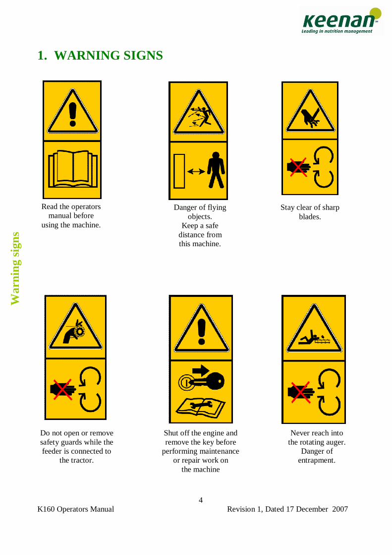
1. WARNING SIGNS
Read the operators manual before
using the machine.
Danger of flying objects.
Keep a safe distance from this machine.
Stay clear of sharp blades.
Do not open or remove safety guards while the feeder is connected to
the tractor.
Shut off the engine and remove the key before
performing maintenance or repair work on
the machine
Never reach into the rotating auger.
Danger of entrapment.
War
ning
sig
ns
K160 Operators Manual Revision 1, Dated 17 December 2007
5
1. WARNING SIGNS
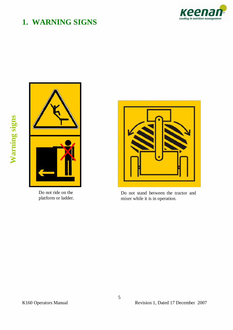
Do not ride on the platform or ladder.
Do not stand between the tractor and mixer while it is in operation.
War
ning
sig
ns
K160 Operators Manual Revision 1, Dated 17 December 2007
6
2. OPERATING PRINCIPLES The K 160�s main operating functions are weighing, chopping/mixing and feeding out. WEIGHING; The K 160 electronic weighing system allows the exact quantity of individual materials to be loaded into the mixing chamber for accurate rationing. Individual loads can be weighed or successive loads accumulated to give total weight of feed. See Section 4 (Weighing system) and the Readout Manual for more detailed information. CHOPPING / MIXING; Load ingredients in sequence recommended by your Keenan system specialist, or as suggested in Section 5 (Operation). For non bale handler models, ensure bales are broken up prior to loading. For bale handlers, wait until the bale has been taken in completely before adding further bales. As a general rule, material should be tumbling freely when mixing. If not then the machine is overloaded and will not achieve the desired mix quality. Mixing is carried out by a centrally-mounted rotor fitted with 6 angled paddles revolving at 6 - 8rpm. Each paddle imparts a shearing action, sweeping the feed ingredients onto the strategically placed knives to produce a consistent and thorough mix with all types of materials, including baled silage/hay, straw, roots and liquids.
CAUTION: For bale handler models, do not load more than one bale at a time.
The angled paddles help mixing by sweeping the material from end to end. The placement of the blades ensures the materials reach optimum size/length, without grinding it down and destroying the all important �scratch factor� of the forages. Mixing time will be determined by the required chop length. Follow procedures contained in this manual or consult your Keenan System specialist for further information.
CAUTION: Overloading will seriously affect machine performance and life, and will invalidate your warranty.
Wei
ghin
g
Cho
ppin
g/ m
ixin
g
K160 Operators Manual Revision 1, Dated 17 December 2007
7
FEEDING OUT; During mixing, the mixing chamber is separated from the feed out chamber by a Variable Feed Control (VFC) or guillotine door, thus ensuring complete mixing. The feed out chamber contains an auger which runs the entire length of the machine. When chopping/mixing is complete, the feed out door/tray should be set to the required position, and the VFC door dropped, allowing the material to be swept up by the paddles and pushed onto the auger � see figure 2. The VFC door should be opened partially at first. As soon as feed is seen discharging then 15-20 seconds should be allowed before opening the VFC door fully. Door position and ground speed should be set to allow an even feed out rate.
CAUTION: The VFC door should only be opened or closed when the PTO is engaged (paddles turning) when material is in the machine.
Fee
ding
out
K160 Operators Manual Revision 1, Dated 17 December 2007
8
2. OPERATING PRINCIPLES MAINTENANCE
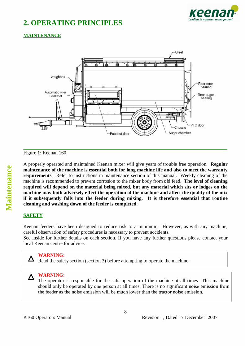
Figure 1: Keenan 160 A properly operated and maintained Keenan mixer will give years of trouble free operation. Regular maintenance of the machine is essential both for long machine life and also to meet the warranty requirements. Refer to instructions in maintenance section of this manual. Weekly cleaning of the machine is recommended to prevent corrosion to the mixer body from old feed. The level of cleaning required will depend on the material being mixed, but any material which sits or lodges on the machine may both adversely effect the operation of the machine and affect the quality of the mix if it subsequently falls into the feeder during mixing. It is therefore essential that routine cleaning and washing down of the feeder is completed. SAFETY Keenan feeders have been designed to reduce risk to a minimum. However, as with any machine, careful observation of safety procedures is necessary to prevent accidents. See inside for further details on each section. If you have any further questions please contact your local Keenan centre for advice.
WARNING: Read the safety section (section 3) before attempting to operate the machine.
WARNING: The operator is responsible for the safe operation of the machine at all times This machine should only be operated by one person at all times. There is no significant noise emission from the feeder as the noise emission will be much lower than the tractor noise emission.
Mai
nten
ance
K160 Operators Manual Revision 1, Dated 17 December 2007
9
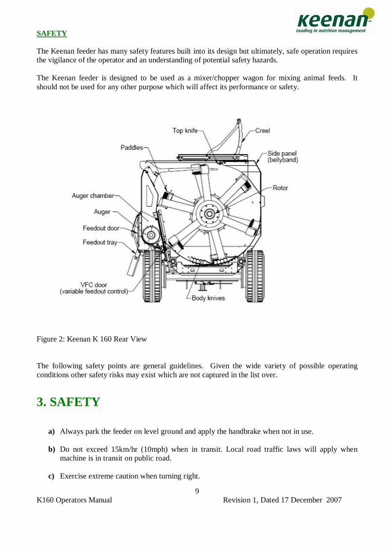
SAFETY The Keenan feeder has many safety features built into its design but ultimately, safe operation requires the vigilance of the operator and an understanding of potential safety hazards. The Keenan feeder is designed to be used as a mixer/chopper wagon for mixing animal feeds. It should not be used for any other purpose which will affect its performance or safety.
Figure 2: Keenan K 160 Rear View
The following safety points are general guidelines. Given the wide variety of possible operating conditions other safety risks may exist which are not captured in the list over.
3. SAFETY
a) Always park the feeder on level ground and apply the handbrake when not in use.
b) Do not exceed 15km/hr (10mph) when in transit. Local road traffic laws will apply when machine is in transit on public road.
c) Exercise extreme caution when turning right.
K160 Operators Manual Revision 1, Dated 17 December 2007
10
d) Do not stand on the ladder whilst the feeder is in transit. The feeder should never be used for
the transport of people, animals or objects.
e) Do not stand between the tractor and feeder while it is in use.
f) Use only a PTO shaft with a properly fitted safety guard and correct shear bolt.
g) Always connect the PTO shaft with the shear bolt end to the machine. The operating speed of the PTO is 540 rpm and the direction of rotation is marked on the front cover. Always use a well maintained PTO shaft and keep the safety covers in good condition.
h) Ensure all trailing leads; hoses etc. are well clear of the PTO.
i) Do not operate the PTO in �ground speed mode�.
j) Make sure all covers/guards are fitted and closed correctly. Never remove guards when the
feeder is connected to the tractor. Ensure that the engine of the tractor is stopped and PTO shaft disconnected before carrying out service or maintenance work and especially if removing trapped objects from the machine.
k) Ensure the feeder and the immediate area surrounding it is clear of people, especially children,
before commencing operation. Ensure that there is sufficient visibility for the operator to observe all danger zones and that the tractor is equipped with mirrors to enable the operator to see both sides of the machine while it is in operation.
l) When connecting the tractor to the feeder only connect using the ring hitch on the feeder to
ensure safe coupling. Ensure that the hitch is connected properly to the tractor and that all pins and clips are properly installed. Then connect the PTO shaft in the correct fashion. Connect the hydraulic hoses ensuring that the functions match the indicated valve on the tractor.
m) When disconnecting always ensure that a stand or jack is used to secure the machine in the park position and ensure that the handbrake is properly applied. Before driving the tractor away from the feeder ensure that all hoses and cables are disconnected.
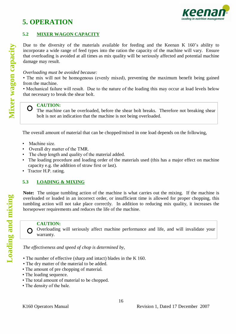
n) Load only from the side indicated � see figure 6 (auger chamber side) using suitable
equipment.
o) Standing level with or above the machine in order to load manually is not permitted. Loading should be carried out with suitable equipment.
p) Regularly inspect all chains (at least weekly), sprockets and moving parts for wear and check
all nuts and bolts for tightness. q) The ladder on the rear of the feeder is to be used as a viewing point for the mixing chamber. It
should not be used as a means of access to the mixing chamber nor onto the body of the feeder. It is strictly forbidden to climb on the upper brim of the machine body. The height of the machine presents a potential fall hazard during entry and exit.
r) Routine cleaning should be carried out using a power hose, with the drain bung open
eliminating any reason to climb into the mixing chamber.
Safe
ty
Safe
ty
K160 Operators Manual Revision 1, Dated 17 December 2007
11
s) The top knife should always be fitted with the supplied guard (figure 4) before routine cleaning or maintenance is carried out. Note: the machine is supplied with a top knife guard which should be removed before the machine is used.
t) It is recommended that only Keenan trained and qualified maintenance personnel enter
the mixing chamber. In the case of an untrained person entering the mixing chamber, at the very minimum, the following precautionary safety guidelines should be strictly adhered at all times. 1. Ensure the PTO is removed. 2. Apply the mixer wagon handbrake and disconnect the tractor on level ground. 3. Use a suitable ladder for access to and from the mixer wagon. Note: The viewing ladder is only used for viewing and not for access to the mixing chamber. 4. Personnel should make themselves familiar with the location of all potential hazards before entering the machine, in particular the location of the top knife and body blades. 5. Use suitable Personnel Protective Equipment and fit blade covers .
u) If the person intending to enter and work within the machine is not confident about doing so safely, then they should contact a Keenan Service Person to complete the work.
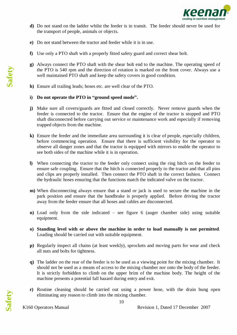
SODAGRAIN. Additional safety instructions and warnings are available and covered in a soda grain leaflet which should be read carefully before soda treating grain. When finished treating grain, clean out any remaining material in the mixing and/or auger chamber by loading in 200-300 Kg of silage or 50 Kg of straw and allow the machine to mix before unloading in the normal manner. Note that when mixing soda grain, the maximum gross load that can be mixed in the Keenan K 160 is 5,000Kg.
Figure 3. Body blade and blade cover
Safe
ty
K160 Operators Manual Revision 1, Dated 17 December 2007
12
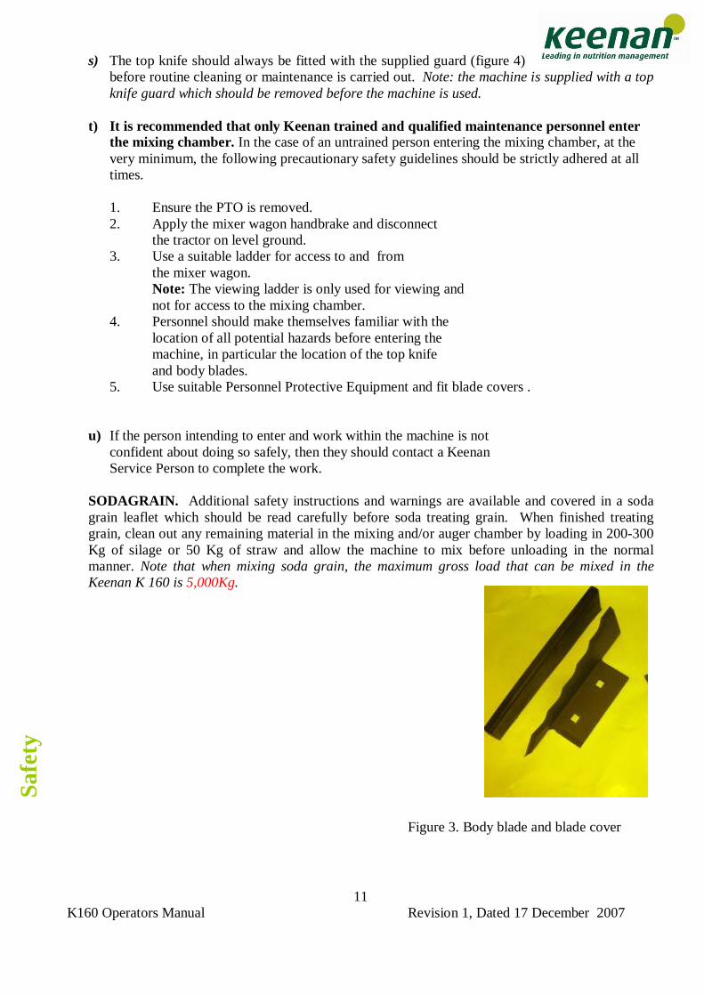
Blade
When entering the choppingmachine, always fit the safetybeading that is provided for the top knife.
Figure 4: Top Knife Protection
4. WEIGHING SYSTEM The weighing system is designed to be simple to operate, accurate and robust. It consists of four load cells connected to an weigh box unit (readout box) at the front of the machine. The system uses 12 volt DC power from the tractor, or battery if fitted. The weigh box unit can be rotated for visibility during loading and from the tractor cab, but should be folded out of the line of the tractor wheel for road work. Loads are displayed in kilograms or lbs with scale increments of 5kg/10lb. The unit is capable of measuring up to 18,140 Kg (39,999 lbs) with the appropriate weight bars. The system is maintenance free being fully electronic with no moving parts. All components are sealed against moisture and dust and are resistant to frost and corrosion. The unit should however not be directly exposed to a high pressure water jet. The weigh box unit may vary from model to model and region to region. A separate manual is supplied for your weigh box unit, which you should refer to for specific operating instructions.
WARNING: Failure to follow the safety guidelines above may lead to accident or injury.
INSTRUCTIONS FOR ELECTRONIC READOUT BOX ARE CONTAINED IN A SEPARATE MANUAL
The
wei
ghin
g sy
stem
K160 Operators Manual Revision 1, Dated 17 December 2007
13
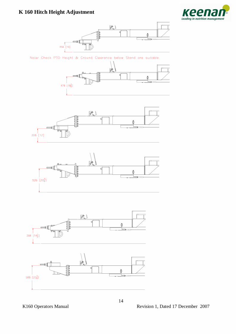
5. OPERATION The simplicity of the K 160 design is reflected in its low power requirement. The power required varies, depending on the mix used, the dry matter and the amount of chopping required. If a tractor is at its limit during mixing this will translate into extra strain on moving parts, as there will be surges in power as the engine recovers during certain periods of the mix. A tractor that has sufficient power will provide a much smoother drive to the mixer-wagon during all stages of operation. 5.1 SET-UP. I. Ensure the machine is level when hitched up. If the machine is unlevel, this can be corrected
by adjusting the hitch height. The hitch height on the K 160 is adjustable from approximately 350mm to 650mm, with 6 different settings; please refer to the drawing on the next page for exact details.
II. The PTO shaft should be attached with the shear bolt end coupled to the machine. Make sure
that the PTO guard is in good condition and well secured.
CAUTION: Do not operate the PTO in �ground speed� mode. Reversing the drive on your machine will cause serious damage.
III. Connect the following hydraulic hoses from the machine to double and single acting spool
valves on the tractor, as appropriate.
Hydraulic and brake hoses Operation Colour Guillotine door Red & yellow Feed out tray Blue Bale Handler creel Green Brakes White
Table 1: Hydraulic and brake hoses IV. Examine the mixing chamber to ensure that; � All blade covers have been removed
� All spare parts and foreign objects have been removed � No damage has occurred during transport. V. Check the weigh box and ensure the power lead from the weighing system is either connected
to the tractor battery via a direct fused line, 7 pin plug or to a 12v battery located in the side box of the feeder. To zero the weighbox press and hold the �zero� and �minus� keys together and hold until �end� appears on the screen then release the buttons . If the power is supplied through a 7 pin lights connection, the tractor lights will need to be switched on to provide power to the weigh box. If you stand on the ladder, at rear of the machine, you can check the reading on the weigh box against your known weight, this may require assistance.
Set-
up
Set-
up
K160 Operators Manual Revision 1, Dated 17 December 2007
14
K 160 Hitch Height Adjustment
K160 Operators Manual Revision 1, Dated 17 December 2007
15
5. OPERATION
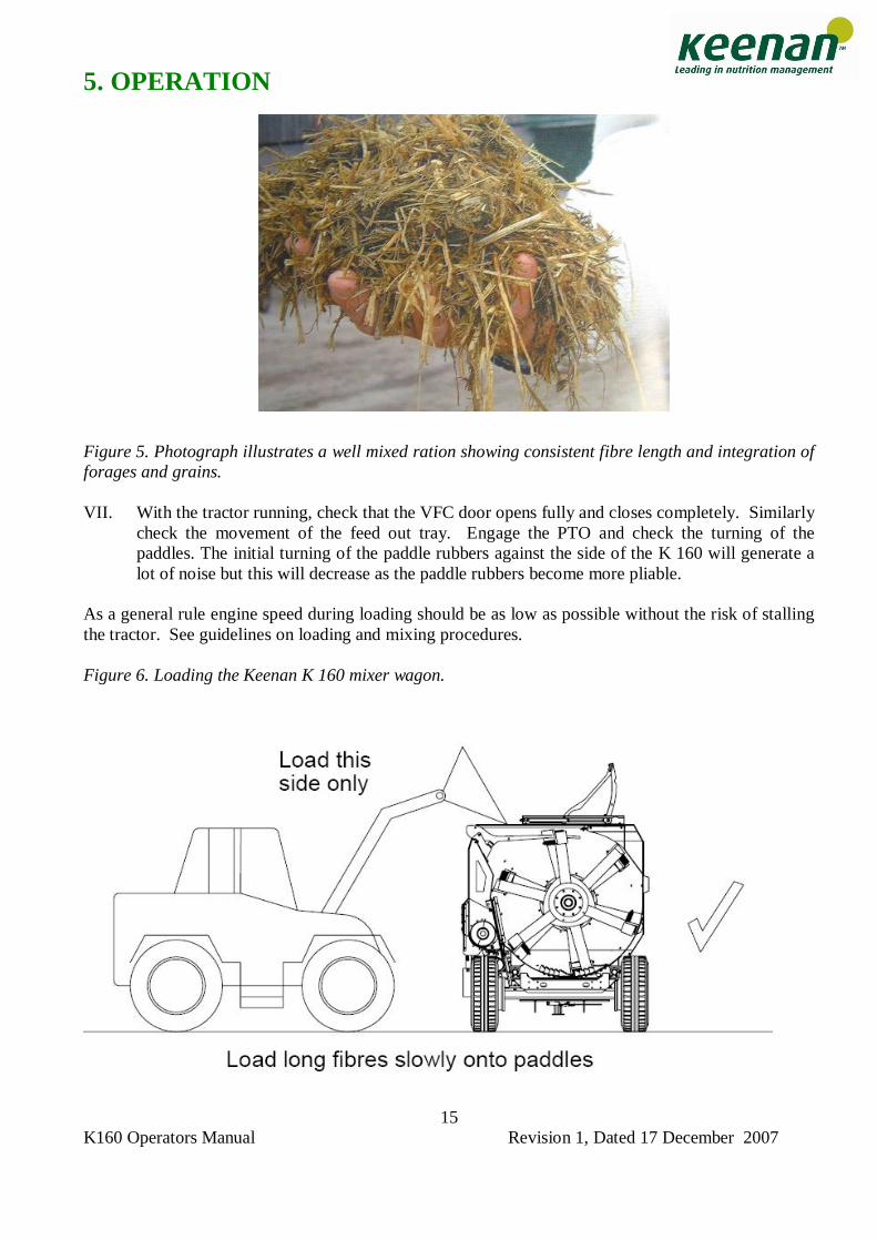
Figure 5. Photograph illustrates a well mixed ration showing consistent fibre length and integration of forages and grains. VII. With the tractor running, check that the VFC door opens fully and closes completely. Similarly
check the movement of the feed out tray. Engage the PTO and check the turning of the paddles. The initial turning of the paddle rubbers against the side of the K 160 will generate a lot of noise but this will decrease as the paddle rubbers become more pliable.
As a general rule engine speed during loading should be as low as possible without the risk of stalling the tractor. See guidelines on loading and mixing procedures. Figure 6. Loading the Keenan K 160 mixer wagon.
K160 Operators Manual Revision 1, Dated 17 December 2007
16
5. OPERATION 5.2 MIXER WAGON CAPACITY Due to the diversity of the materials available for feeding and the Keenan K 160�s ability to incorporate a wide range of feed types into the ration the capacity of the machine will vary. Ensure that overloading is avoided at all times as mix quality will be seriously affected and potential machine damage may result. Overloading must be avoided because: � The mix will not be homogenous (evenly mixed), preventing the maximum benefit being gained from the machine. � Mechanical failure will result. Due to the nature of the loading this may occur at load levels below that necessary to break the shear bolt.
The overall amount of material that can be chopped/mixed in one load depends on the following, � Machine size. � Overall dry matter of the TMR. � The chop length and quality of the material added. � The loading procedure and loading order of the materials used (this has a major effect on machine
capacity e.g. the addition of straw first or last). � Tractor H.P. rating. 5.3 LOADING & MIXING Note: The unique tumbling action of the machine is what carries out the mixing. If the machine is overloaded or loaded in an incorrect order, or insufficient time is allowed for proper chopping, this tumbling action will not take place correctly. In addition to reducing mix quality, it increases the horsepower requirements and reduces the life of the machine.
The effectiveness and speed of chop is determined by, � The number of effective (sharp and intact) blades in the K 160. � The dry matter of the material to be added. � The amount of pre chopping of material. � The loading sequence. � The total amount of material to be chopped. � The density of the bale.
CAUTION: The machine can be overloaded, before the shear bolt breaks. Therefore not breaking shear bolt is not an indication that the machine is not being overloaded.
CAUTION: Overloading will seriously affect machine performance and life, and will invalidate your warranty.
Loa
ding
and
mix
ing
M
ixer
wag
on c
apac
ity
K160 Operators Manual Revision 1, Dated 17 December 2007
17
5. OPERATING THE KEENAN K 160
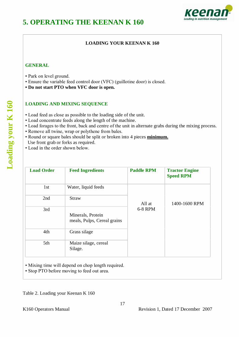
Table 2. Loading your Keenan K 160
LOADING YOUR KEENAN K 160
GENERAL � Park on level ground. � Ensure the variable feed control door (VFC) (guillotine door) is closed. � Do not start PTO when VFC door is open. LOADING AND MIXING SEQUENCE � Load feed as close as possible to the loading side of the unit. � Load concentrate feeds along the length of the machine. � Load forages to the front, back and centre of the unit in alternate grabs during the mixing process. � Remove all twine, wrap or polythene from bales. � Round or square bales should be split or broken into 4 pieces minimum. Use front grab or forks as required. � Load in the order shown below.
Load Order Feed Ingredients
Paddle RPM Tractor Engine Speed RPM
1st
Water, liquid feeds
2nd Straw
3rd Minerals, Protein meals, Pulps, Cereal grains
4th Grass silage
5th Maize silage, cereal
Silage.
All at
6-8 RPM
1400-1600 RPM
� Mixing time will depend on chop length required. � Stop PTO before moving to feed out area.
Loa
ding
you
r K
160
K160 Operators Manual Revision 1, Dated 17 December 2007
18
5. OPERATING THE KEENAN BALE HANDLER
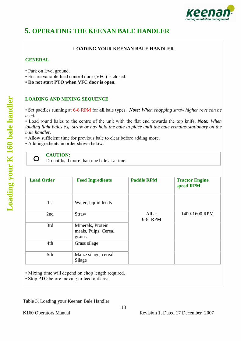
Table 3. Loading your Keenan Bale Handler
LOADING YOUR KEENAN BALE HANDLER
GENERAL � Park on level ground. � Ensure variable feed control door (VFC) is closed. � Do not start PTO when VFC door is open. LOADING AND MIXING SEQUENCE � Set paddles running at 6-8 RPM for all bale types. Note: When chopping straw higher revs can be used. � Load round bales to the centre of the unit with the flat end towards the top knife. Note: When loading light bales e.g. straw or hay hold the bale in place until the bale remains stationary on the bale handler. � Allow sufficient time for previous bale to clear before adding more. � Add ingredients in order shown below: CAUTION: Do not load more than one bale at a time.
Load Order Feed Ingredients
Paddle RPM Tractor Engine speed RPM
1st
Water, liquid feeds
2nd
Straw
3rd
Minerals, Protein meals, Pulps, Cereal grains
4th
Grass silage
5th
Maize silage, cereal Silage
All at 6-8 RPM
1400-1600 RPM
� Mixing time will depend on chop length required. � Stop PTO before moving to feed out area.
Loa
ding
you
r K
160
bal
e ha
ndle
r
K160 Operators Manual Revision 1, Dated 17 December 2007
19
Inst
ruct
ions
L
oadi
ng y
our
K 1
60
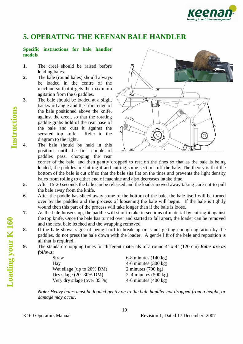
5. OPERATING THE KEENAN BALE HANDLER Specific instructions for bale handler models 1. The creel should be raised before
loading bales. 2. The bale (round bales) should always
be loaded in the centre of the machine so that it gets the maximum agitation from the 6 paddles.
3. The bale should be loaded at a slight backward angle and the front edge of the bale positioned above the knife, against the creel, so that the rotating paddle grabs hold of the rear base of the bale and cuts it against the serrated top knife. Refer to the diagram to the right.
4. The bale should be held in this position, until the first couple of paddles pass, chopping the rear corner of the bale, and then gently dropped to rest on the tines so that as the bale is being loaded, the paddles are hitting it and cutting some sections off the bale. The theory is that the bottom of the bale is cut off so that the bale sits flat on the tines and prevents the light density bales from rolling to either end of machine and also decreases intake time.
5. After 15-20 seconds the bale can be released and the loader moved away taking care not to pull the bale away from the knife.
6. After the paddle has sliced away some of the bottom of the bale, the bale itself will be turned over by the paddles and the process of loosening the bale will begin. If the bale is tightly wound then this part of the process will take longer than if the bale is loose.
7. As the bale loosens up, the paddle will start to take in sections of material by cutting it against the top knife. Once the bale has turned over and started to fall apart, the loader can be removed and the next bale fetched and the wrapping removed.
8. If the bale shows signs of being hard to break up or is not getting enough agitation by the paddles, do not press the bale down with the loader. A gentle lift of the bale and reposition is all that is required.
9. The standard chopping times for different materials of a round 4� x 4� (120 cm) Bales are as follows:
Straw 6-8 minutes (140 kg) Hay 4-6 minutes (300 kg) Wet silage (up to 20% DM) 2 minutes (700 kg) Dry silage (20- 30% DM) 2�4 minutes (500 kg) Very dry silage (over 35 %) 4-6 minutes (400 kg)
Note: Heavy bales must be loaded gently on to the bale handler not dropped from a height, or damage may occur.
K160 Operators Manual Revision 1, Dated 17 December 2007
20
10. These times are achievable if the bale is loaded in the correct position and the loading method as described above is followed. These times may vary slightly depending on the tightness of the bale and the behaviour of the bale when it is being chopped.
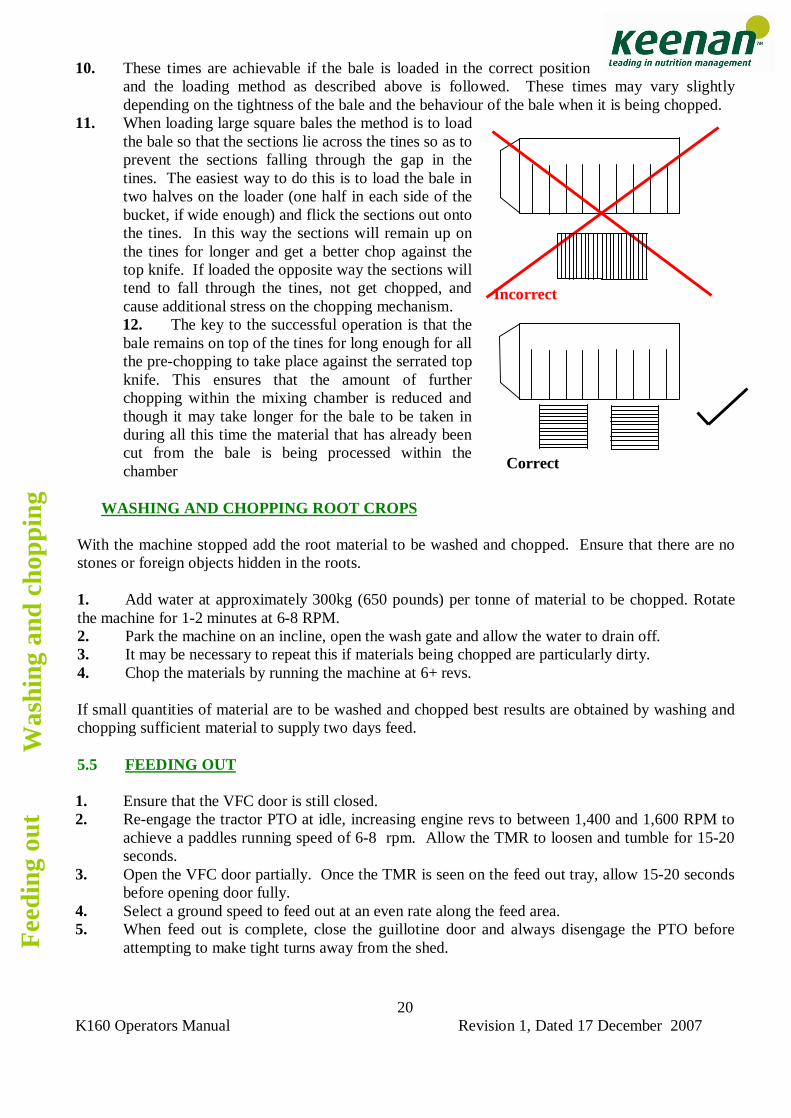
11. When loading large square bales the method is to load the bale so that the sections lie across the tines so as to prevent the sections falling through the gap in the tines. The easiest way to do this is to load the bale in two halves on the loader (one half in each side of the bucket, if wide enough) and flick the sections out onto the tines. In this way the sections will remain up on the tines for longer and get a better chop against the top knife. If loaded the opposite way the sections will tend to fall through the tines, not get chopped, and cause additional stress on the chopping mechanism. 12. The key to the successful operation is that the bale remains on top of the tines for long enough for all the pre-chopping to take place against the serrated top knife. This ensures that the amount of further chopping within the mixing chamber is reduced and though it may take longer for the bale to be taken in during all this time the material that has already been cut from the bale is being processed within the chamber
WASHING AND CHOPPING ROOT CROPS
With the machine stopped add the root material to be washed and chopped. Ensure that there are no stones or foreign objects hidden in the roots. 1. Add water at approximately 300kg (650 pounds) per tonne of material to be chopped. Rotate the machine for 1-2 minutes at 6-8 RPM. 2. Park the machine on an incline, open the wash gate and allow the water to drain off. 3. It may be necessary to repeat this if materials being chopped are particularly dirty. 4. Chop the materials by running the machine at 6+ revs. If small quantities of material are to be washed and chopped best results are obtained by washing and chopping sufficient material to supply two days feed. 5.5 FEEDING OUT 1. Ensure that the VFC door is still closed. 2. Re-engage the tractor PTO at idle, increasing engine revs to between 1,400 and 1,600 RPM to
achieve a paddles running speed of 6-8 rpm. Allow the TMR to loosen and tumble for 15-20 seconds.
3. Open the VFC door partially. Once the TMR is seen on the feed out tray, allow 15-20 seconds before opening door fully.
4. Select a ground speed to feed out at an even rate along the feed area. 5. When feed out is complete, close the guillotine door and always disengage the PTO before
attempting to make tight turns away from the shed.
Was
hing
and
cho
ppin
g
Fee
ding
out
Incorrect
Correct
K160 Operators Manual Revision 1, Dated 17 December 2007
21
6. MAINTENANCE The K 160 has been designed for optimum performance with a minimum of maintenance. Chains, bearings and grease points have been kept to a minimum without compromising function. All components are of high quality and provide excellent durability. Regular, routine maintenance will ensure your K 160 gives you the best results with a minimum of problems.
WARNING: Prior to carrying out any maintenance on the machine, always disconnect the P.T.O. and hydraulic hoses from the tractor and ensure tractor engine is stopped. Observe safety precautions at all times when working on machine, read Section 3 on safety before attempting to work on machine.
The maximum allowable pressure in the hydraulic circuit is 170 bar and flow rates of 40 liters/min are used. Replacement hoses should comply with DIN EN 853. When replacing hydraulic hoses wear suitable protective equipment. 6.1 CHAINS
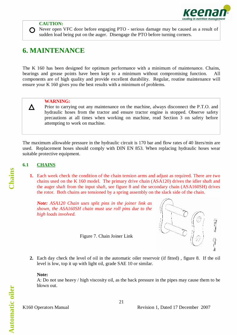
1. Each week check the condition of the chain tension arms and adjust as required. There are two chains used on the K 160 model. The primary drive chain (ASA120) drives the idler shaft and the auger shaft from the input shaft, see figure 8 and the secondary chain (ASA160SH) drives the rotor. Both chains are tensioned by a spring assembly on the slack side of the chain. Note: ASA120 Chain uses split pins in the joiner link as shown, the ASA160SH chain must use roll pins due to the high loads involved.
Figure 7. Chain Joiner Link
2. Each day check the level of oil in the automatic oiler reservoir (if fitted) , figure 8. If the oil level is low, top it up with light oil, grade SAE 10 or similar. Note: A: Do not use heavy / high viscosity oil, as the back pressure in the pipes may cause them to be blown out.
CAUTION: Never open VFC door before engaging PTO - serious damage may be caused as a result of sudden load being put on the auger. Disengage the PTO before turning corners.
Cha
ins
Aut
omat
ic o
iler
K160 Operators Manual Revision 1, Dated 17 December 2007
22
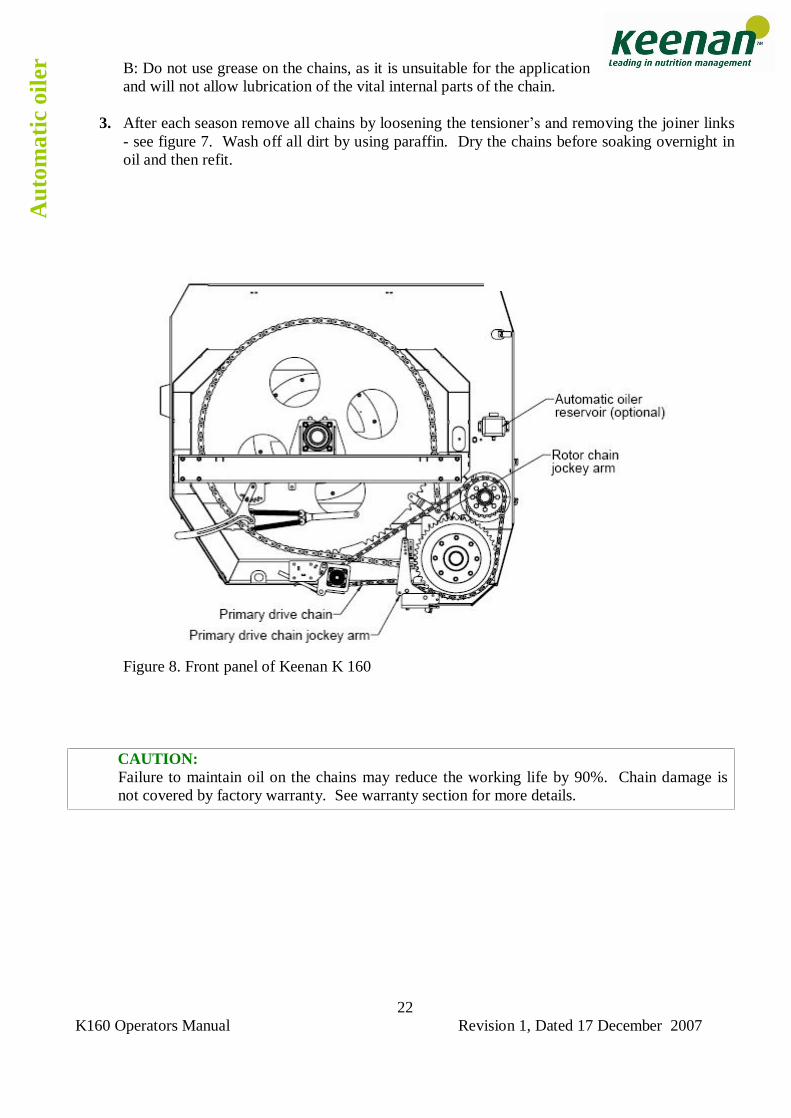
B: Do not use grease on the chains, as it is unsuitable for the application and will not allow lubrication of the vital internal parts of the chain.
3. After each season remove all chains by loosening the tensioner�s and removing the joiner links
- see figure 7. Wash off all dirt by using paraffin. Dry the chains before soaking overnight in oil and then refit.
Figure 8. Front panel of Keenan K 160
CAUTION: Failure to maintain oil on the chains may reduce the working life by 90%. Chain damage is not covered by factory warranty. See warranty section for more details.
Aut
omat
ic o
iler
K160 Operators Manual Revision 1, Dated 17 December 2007
23
6. MAINTENANCE
Model K 160 Primary Drive chain ASA 120 Links 90 (inc.joiner) Pitch (mm) 38.1 Pitch (inches) 1.5� Chain length (mm) 3,427.65 Chain length (inches) 135 Rotor drive chain ASA 160 Links 120 (inc.joiner) Pitch (mm) 50.8 Pitch (inches) 2� Chain length (mm) 6,093.6 Chain length (inches) 240
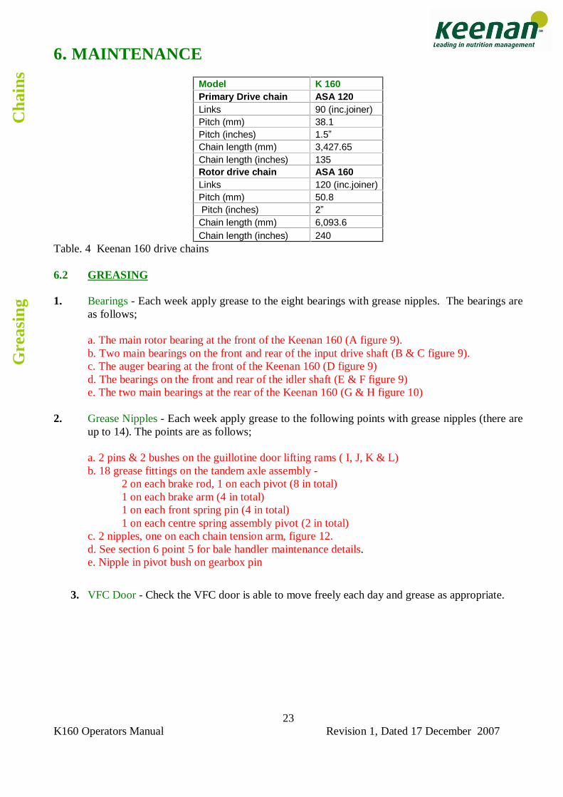
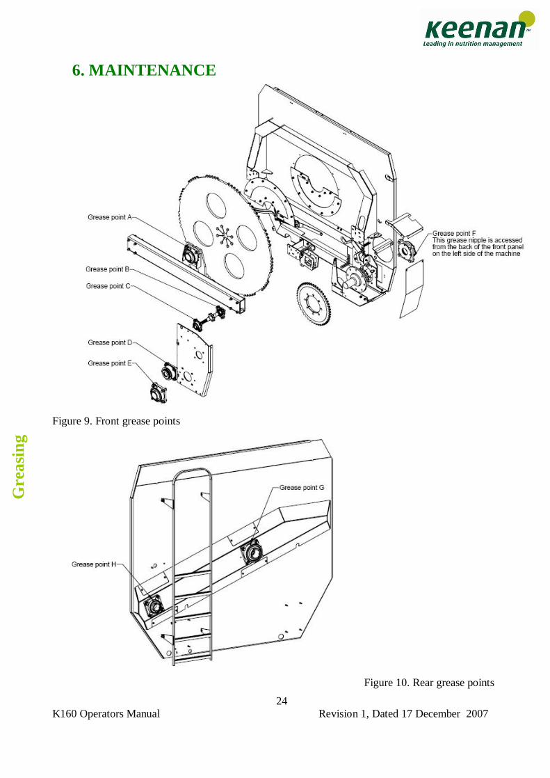
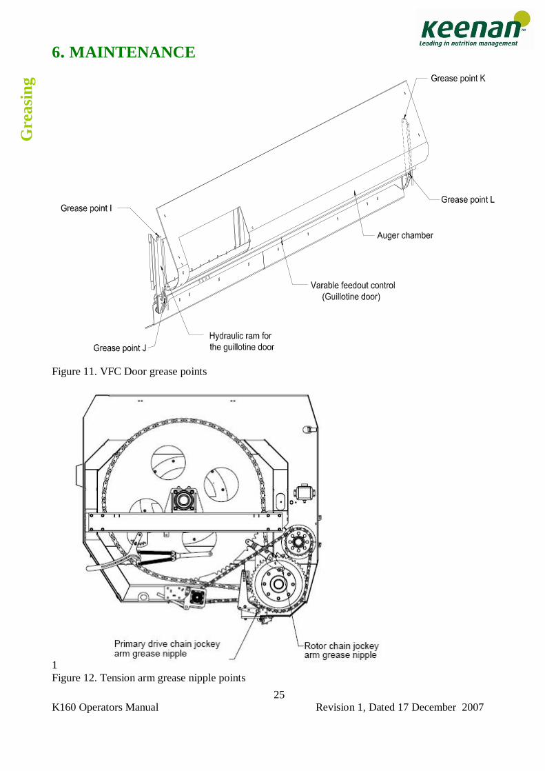
Table. 4 Keenan 160 drive chains 6.2 GREASING 1. Bearings - Each week apply grease to the eight bearings with grease nipples. The bearings are
as follows; a. The main rotor bearing at the front of the Keenan 160 (A figure 9). b. Two main bearings on the front and rear of the input drive shaft (B & C figure 9). c. The auger bearing at the front of the Keenan 160 (D figure 9) d. The bearings on the front and rear of the idler shaft (E & F figure 9) e. The two main bearings at the rear of the Keenan 160 (G & H figure 10) 2. Grease Nipples - Each week apply grease to the following points with grease nipples (there are
up to 14). The points are as follows; a. 2 pins & 2 bushes on the guillotine door lifting rams ( I, J, K & L) b. 18 grease fittings on the tandem axle assembly -
2 on each brake rod, 1 on each pivot (8 in total) 1 on each brake arm (4 in total) 1 on each front spring pin (4 in total) 1 on each centre spring assembly pivot (2 in total)
c. 2 nipples, one on each chain tension arm, figure 12. d. See section 6 point 5 for bale handler maintenance details. e. Nipple in pivot bush on gearbox pin
3. VFC Door - Check the VFC door is able to move freely each day and grease as appropriate.
Gre
asin
g
Cha
ins
K160 Operators Manual Revision 1, Dated 17 December 2007
24
6. MAINTENANCE
Figure 9. Front grease points
Figure 10. Rear grease points
Gre
asin
g
K160 Operators Manual Revision 1, Dated 17 December 2007
25
6. MAINTENANCE
Figure 11. VFC Door grease points
1 Figure 12. Tension arm grease nipple points
Gre
asin
g
K160 Operators Manual Revision 1, Dated 17 December 2007
26
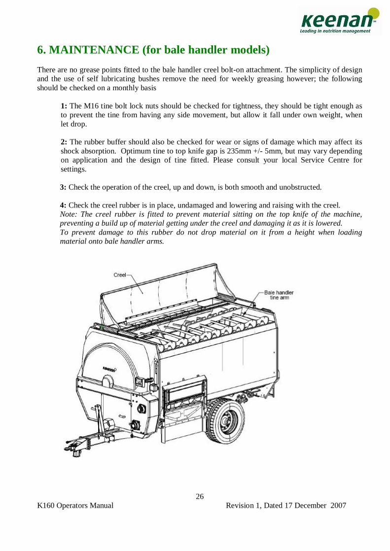
6. MAINTENANCE (for bale handler models) There are no grease points fitted to the bale handler creel bolt-on attachment. The simplicity of design and the use of self lubricating bushes remove the need for weekly greasing however; the following should be checked on a monthly basis
1: The M16 tine bolt lock nuts should be checked for tightness, they should be tight enough as to prevent the tine from having any side movement, but allow it fall under own weight, when let drop. 2: The rubber buffer should also be checked for wear or signs of damage which may affect its shock absorption. Optimum tine to top knife gap is 235mm +/- 5mm, but may vary depending on application and the design of tine fitted. Please consult your local Service Centre for settings. 3: Check the operation of the creel, up and down, is both smooth and unobstructed. 4: Check the creel rubber is in place, undamaged and lowering and raising with the creel. Note: The creel rubber is fitted to prevent material sitting on the top knife of the machine, preventing a build up of material getting under the creel and damaging it as it is lowered. To prevent damage to this rubber do not drop material on it from a height when loading material onto bale handler arms.
K160 Operators Manual Revision 1, Dated 17 December 2007
27
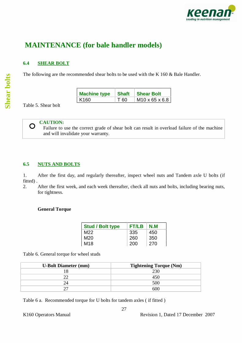
MAINTENANCE (for bale handler models) 6.4 SHEAR BOLT
The following are the recommended shear bolts to be used with the K 160 & Bale Handler.
Table 5. Shear bolt
CAUTION: Failure to use the correct grade of shear bolt can result in overload failure of the machine and will invalidate your warranty.
6.5 NUTS AND BOLTS 1. After the first day, and regularly thereafter, inspect wheel nuts and Tandem axle U bolts (if fitted) . 2. After the first week, and each week thereafter, check all nuts and bolts, including bearing nuts,
for tightness. General Torque Table 6. General torque for wheel studs
U-Bolt Diameter (mm) Tightening Torque (Nm) 18 230 22 450 24 500 27 600
Table 6 a. Recommended torque for U bolts for tandem axles ( if fitted )
Machine type Shaft Shear Bolt K160 T 60 M10 x 65 x 6.8
Stud / Bolt type FT/LB N.M M22 335 450 M20 260 350 M18 200 270
Shea
r bo
lts
K160 Operators Manual Revision 1, Dated 17 December 2007
28
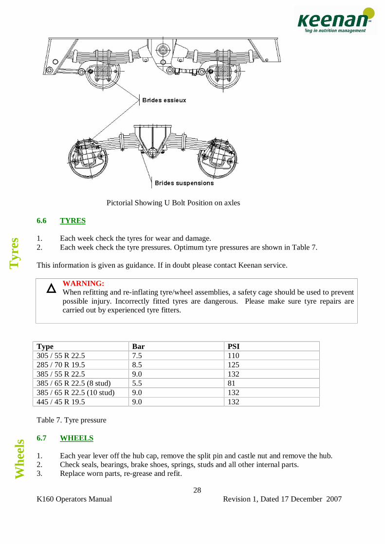
Pictorial Showing U Bolt Position on axles
6.6 TYRES 1. Each week check the tyres for wear and damage. 2. Each week check the tyre pressures. Optimum tyre pressures are shown in Table 7. This information is given as guidance. If in doubt please contact Keenan service.
WARNING: When refitting and re-inflating tyre/wheel assemblies, a safety cage should be used to prevent possible injury. Incorrectly fitted tyres are dangerous. Please make sure tyre repairs are carried out by experienced tyre fitters.
Type Bar PSI 305 / 55 R 22.5 7.5 110 285 / 70 R 19.5 8.5 125 385 / 55 R 22.5 9.0 132 385 / 65 R 22.5 (8 stud) 5.5 81 385 / 65 R 22.5 (10 stud) 9.0 132 445 / 45 R 19.5 9.0 132 Table 7. Tyre pressure 6.7 WHEELS 1. Each year lever off the hub cap, remove the split pin and castle nut and remove the hub. 2. Check seals, bearings, brake shoes, springs, studs and all other internal parts. 3. Replace worn parts, re-grease and refit.
Tyr
es
Whe
els
K160 Operators Manual Revision 1, Dated 17 December 2007
29
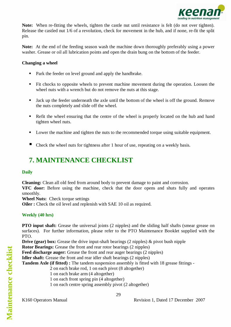
Note: When re-fitting the wheels, tighten the castle nut until resistance is felt (do not over tighten). Release the castled nut 1/6 of a revolution, check for movement in the hub, and if none, re-fit the split pin. Note: At the end of the feeding season wash the machine down thoroughly preferably using a power washer. Grease or oil all lubrication points and open the drain bung on the bottom of the feeder. Changing a wheel
Park the feeder on level ground and apply the handbrake.
Fit chocks to opposite wheels to prevent machine movement during the operation. Loosen the wheel nuts with a wrench but do not remove the nuts at this stage.
Jack up the feeder underneath the axle until the bottom of the wheel is off the ground. Remove
the nuts completely and slide off the wheel.
Refit the wheel ensuring that the centre of the wheel is properly located on the hub and hand tighten wheel nuts.
Lower the machine and tighten the nuts to the recommended torque using suitable equipment.
Check the wheel nuts for tightness after 1 hour of use, repeating on a weekly basis.
7. MAINTENANCE CHECKLIST Daily Cleaning: Clean all old feed from around body to prevent damage to paint and corrosion. VFC door: Before using the machine, check that the door opens and shuts fully and operates smoothly. Wheel Nuts: Check torque settings Oiler : Check the oil level and replenish with SAE 10 oil as required. Weekly (40 hrs) PTO input shaft: Grease the universal joints (2 nipples) and the sliding half shafts (smear grease on surfaces). For further information, please refer to the PTO Maintenance Booklet supplied with the PTO. Drive (gear) box: Grease the drive input-shaft bearings (2 nipples) & pivot bush nipple Rotor Bearings: Grease the front and rear rotor bearings (2 nipples) Feed discharge auger: Grease the front and rear auger bearings (2 nipples) Idler shaft: Grease the front and rear idler shaft bearings (2 nipples) Tandem Axle (if fitted) : The tandem suspension assembly is fitted with 18 grease fittings -
2 on each brake rod, 1 on each pivot (8 altogether) 1 on each brake arm (4 altogether) 1 on each front spring pin (4 altogether) 1 on each centre spring assembly pivot (2 altogether)
Mai
nten
ance
che
cklis
t
K160 Operators Manual Revision 1, Dated 17 December 2007
30
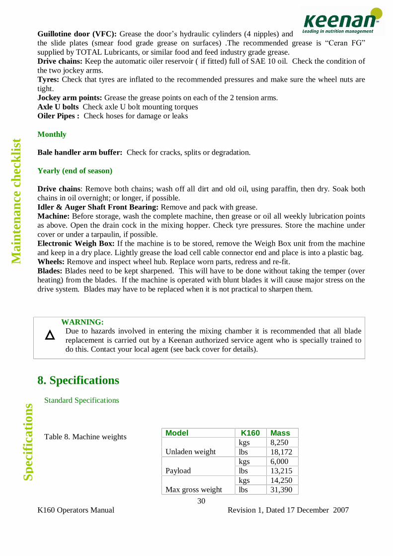
Guillotine door (VFC): Grease the door�s hydraulic cylinders (4 nipples) and the slide plates (smear food grade grease on surfaces) .The recommended grease is �Ceran FG� supplied by TOTAL Lubricants, or similar food and feed industry grade grease. Drive chains: Keep the automatic oiler reservoir ( if fitted) full of SAE 10 oil. Check the condition of the two jockey arms. Tyres: Check that tyres are inflated to the recommended pressures and make sure the wheel nuts are tight. Jockey arm points: Grease the grease points on each of the 2 tension arms. Axle U bolts Check axle U bolt mounting torques Oiler Pipes : Check hoses for damage or leaks Monthly Bale handler arm buffer: Check for cracks, splits or degradation. Yearly (end of season) Drive chains: Remove both chains; wash off all dirt and old oil, using paraffin, then dry. Soak both chains in oil overnight; or longer, if possible. Idler & Auger Shaft Front Bearing: Remove and pack with grease. Machine: Before storage, wash the complete machine, then grease or oil all weekly lubrication points as above. Open the drain cock in the mixing hopper. Check tyre pressures. Store the machine under cover or under a tarpaulin, if possible. Electronic Weigh Box: If the machine is to be stored, remove the Weigh Box unit from the machine and keep in a dry place. Lightly grease the load cell cable connector end and place is into a plastic bag. Wheels: Remove and inspect wheel hub. Replace worn parts, redress and re-fit. Blades: Blades need to be kept sharpened. This will have to be done without taking the temper (over heating) from the blades. If the machine is operated with blunt blades it will cause major stress on the drive system. Blades may have to be replaced when it is not practical to sharpen them.
8. Specifications
Standard Specifications
Table 8. Machine weights
WARNING: Due to hazards involved in entering the mixing chamber it is recommended that all blade replacement is carried out by a Keenan authorized service agent who is specially trained to do this. Contact your local agent (see back cover for details).
Model K160 Mass kgs 8,250
Unladen weight lbs 18,172 kgs 6,000
Payload lbs 13,215 kgs 14,250
Max gross weight lbs 31,390
Mai
nten
ance
che
cklis
t
Spec
ific
atio
ns
K160 Operators Manual Revision 1, Dated 17 December 2007
31
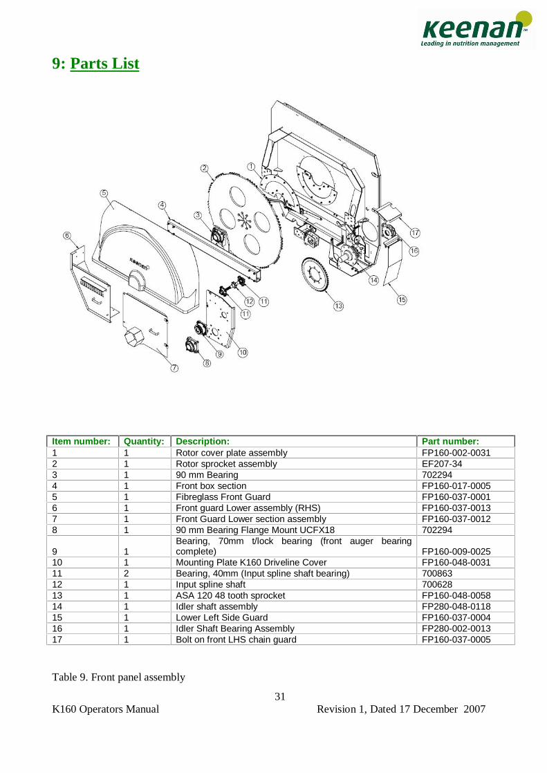
9: Parts List
Item number: Quantity: Description: Part number: 1 1 Rotor cover plate assembly FP160-002-0031 2 1 Rotor sprocket assembly EF207-34 3 1 90 mm Bearing 702294 4 1 Front box section FP160-017-0005 5 1 Fibreglass Front Guard FP160-037-0001 6 1 Front guard Lower assembly (RHS) FP160-037-0013 7 1 Front Guard Lower section assembly FP160-037-0012 8 1 90 mm Bearing Flange Mount UCFX18 702294
9 1 Bearing, 70mm t/lock bearing (front auger bearing complete) FP160-009-0025
10 1 Mounting Plate K160 Driveline Cover FP160-048-0031 11 2 Bearing, 40mm (Input spline shaft bearing) 700863 12 1 Input spline shaft 700628 13 1 ASA 120 48 tooth sprocket FP160-048-0058 14 1 Idler shaft assembly FP280-048-0118 15 1 Lower Left Side Guard FP160-037-0004 16 1 Idler Shaft Bearing Assembly FP280-002-0013 17 1 Bolt on front LHS chain guard FP160-037-0005 Table 9. Front panel assembly
K160 Operators Manual Revision 1, Dated 17 December 2007
32
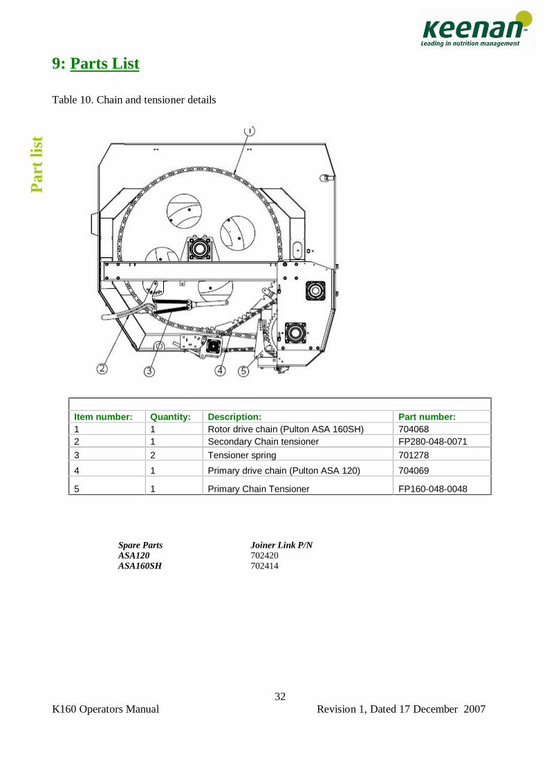
9: Parts List Table 10. Chain and tensioner details
Spare Parts Joiner Link P/N ASA120 702420 ASA160SH 702414
Item number: Quantity: Description: Part number: 1 1 Rotor drive chain (Pulton ASA 160SH) 704068 2 1 Secondary Chain tensioner FP280-048-0071
3 2 Tensioner spring 701278
4 1 Primary drive chain (Pulton ASA 120) 704069
5 1 Primary Chain Tensioner FP160-048-0048
P
art
list
K160 Operators Manual Revision 1, Dated 17 December 2007
33
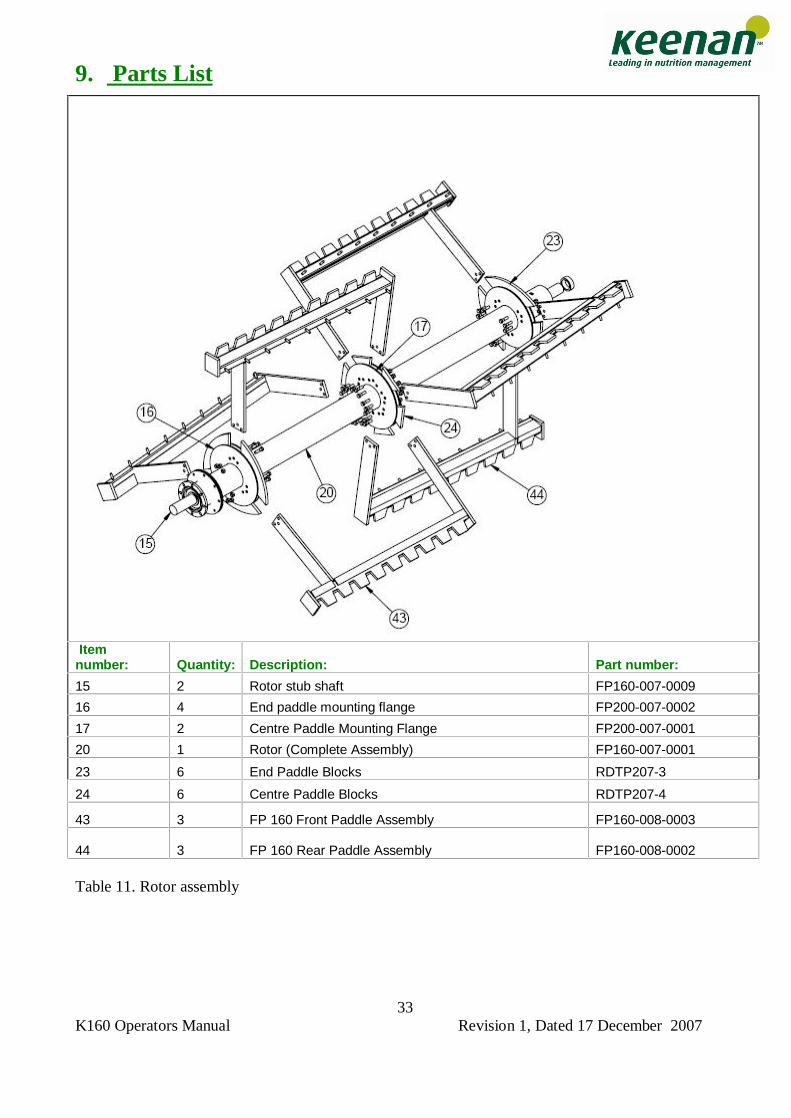
9. Parts List
Table 11. Rotor assembly
Item number: Quantity: Description: Part number:
15 2 Rotor stub shaft FP160-007-0009
16 4 End paddle mounting flange FP200-007-0002
17 2 Centre Paddle Mounting Flange FP200-007-0001
20 1 Rotor (Complete Assembly) FP160-007-0001
23 6 End Paddle Blocks RDTP207-3
24 6 Centre Paddle Blocks RDTP207-4
43 3 FP 160 Front Paddle Assembly FP160-008-0003
44 3 FP 160 Rear Paddle Assembly FP160-008-0002
K160 Operators Manual Revision 1, Dated 17 December 2007
34
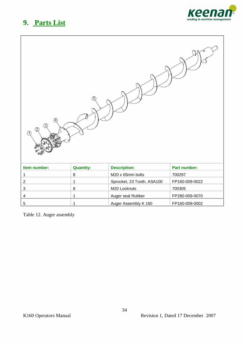
9. Parts List
Table 12. Auger assembly
Item number: Quantity: Description: Part number:
1 8 M20 x 65mm bolts 700297
2 1 Sprocket, 23 Tooth, ASA100 FP160-009-0022
3 8 M20 Locknuts 700305
4 1 Auger seal Rubber FP280-009-0070
5 1 Auger Assembly K 160 FP160-009-0002
K160 Operators Manual Revision 1, Dated 17 December 2007
35
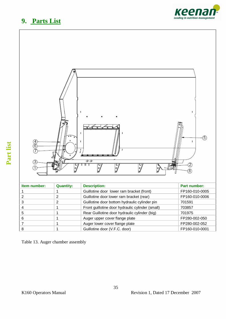
9. Parts List
Table 13. Auger chamber assembly
Item number: Quantity: Description: Part number: 1 1 Guillotine door lower ram bracket (front) FP160-010-0005 2 2 Guillotine door lower ram bracket (rear) FP160-010-0006 3 2 Guillotine door bottom hydraulic cylinder pin 701591 4 1 Front guillotine door hydraulic cylinder (small) 703857 5 1 Rear Guillotine door hydraulic cylinder (big) 701975 6 1 Auger upper cover flange plate FP280-002-050 7 1 Auger lower cover flange plate FP280-002-052 8 1 Guillotine door (V.F.C. door) FP160-010-0001
Par
t lis
t
K160 Operators Manual Revision 1, Dated 17 December 2007
36
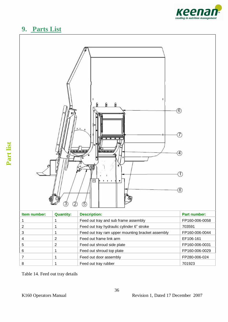
9. Parts List
Table 14. Feed out tray details
Item number: Quantity: Description: Part number:
1 1 Feed out tray and sub frame assembly FP160-006-0058
2 1 Feed out tray hydraulic cylinder 6� stroke 703591
3 1 Feed out tray ram upper mounting bracket assembly FP160-006-0044
4 2 Feed out frame link arm EF106-161
5 2 Feed out shroud side plate FP160-006-0031
6 1 Feed out shroud top plate FP160-006-0029
7 1 Feed out door assembly FP280-006-024
8 1 Feed out tray rubber 701923
Par
t lis
t
K160 Operators Manual Revision 1, Dated 17 December 2007
37
9. Parts List
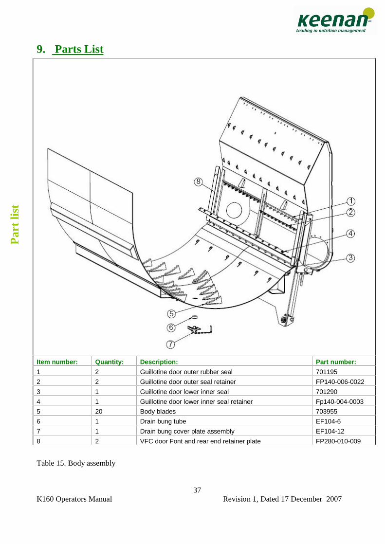
Table 15. Body assembly
Item number: Quantity: Description: Part number:
1 2 Guillotine door outer rubber seal 701195
2 2 Guillotine door outer seal retainer FP140-006-0022
3 1 Guillotine door lower inner seal 701290
4 1 Guillotine door lower inner seal retainer Fp140-004-0003
5 20 Body blades 703955
6 1 Drain bung tube EF104-6
7 1 Drain bung cover plate assembly EF104-12
8 2 VFC door Font and rear end retainer plate FP280-010-009
Par
t lis
t
K160 Operators Manual Revision 1, Dated 17 December 2007
38
9. Parts List
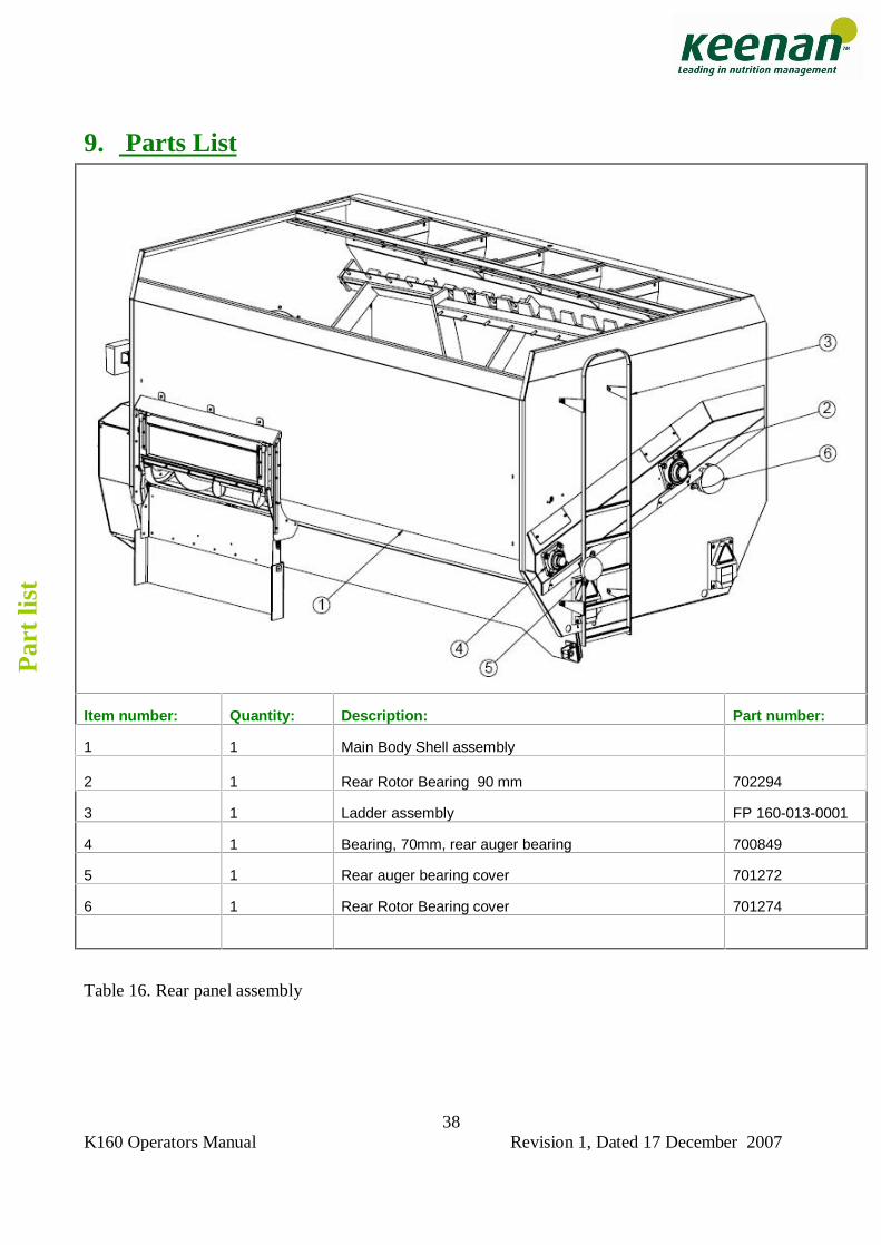
Table 16. Rear panel assembly
Item number: Quantity: Description: Part number:
1 1 Main Body Shell assembly 2
1
Rear Rotor Bearing 90 mm 702294
3 1 Ladder assembly FP 160-013-0001
4 1 Bearing, 70mm, rear auger bearing 700849
5 1 Rear auger bearing cover 701272
6 1 Rear Rotor Bearing cover 701274
Par
t lis
t
K160 Operators Manual Revision 1, Dated 17 December 2007
39
9. Parts List
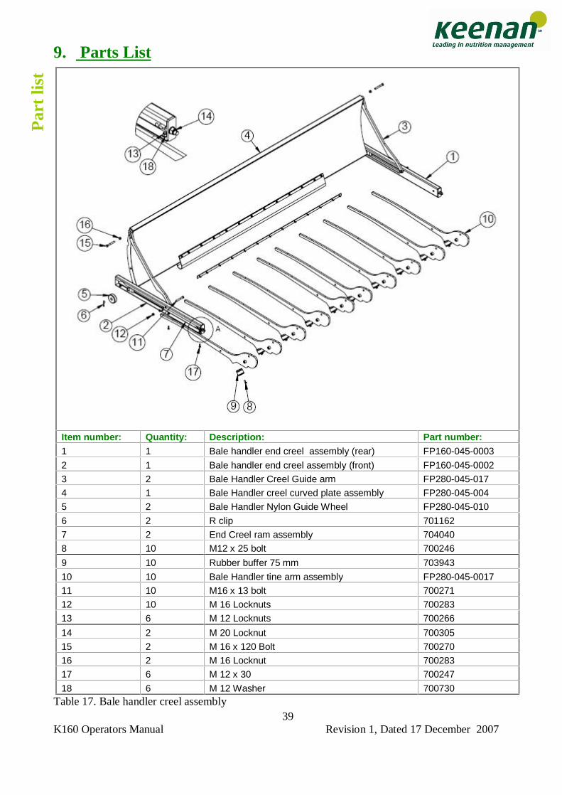
Table 17. Bale handler creel assembly
Item number: Quantity: Description: Part number: 1 1 Bale handler end creel assembly (rear) FP160-045-0003
2 1 Bale handler end creel assembly (front) FP160-045-0002
3 2 Bale Handler Creel Guide arm FP280-045-017
4 1 Bale Handler creel curved plate assembly FP280-045-004
5 2 Bale Handler Nylon Guide Wheel FP280-045-010
6 2 R clip 701162
7 2 End Creel ram assembly 704040
8 10 M12 x 25 bolt 700246
9 10 Rubber buffer 75 mm 703943
10 10 Bale Handler tine arm assembly FP280-045-0017
11 10 M16 x 13 bolt 700271
12 10 M 16 Locknuts 700283
13 6 M 12 Locknuts 700266
14 2 M 20 Locknut 700305
15 2 M 16 x 120 Bolt 700270
16 2 M 16 Locknut 700283
17 6 M 12 x 30 700247
18 6 M 12 Washer 700730
Par
t lis
t
K160 Operators Manual Revision 1, Dated 17 December 2007
40
9. Parts List
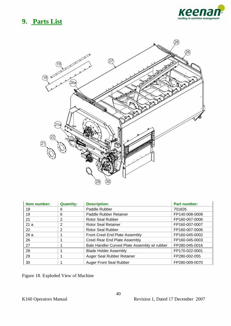
Figure 18. Exploded View of Machine
Item number: Quantity: Description: Part number: 18 6 Paddle Rubber 701826 19 6 Paddle Rubber Retainer FP140-008-0009 21 2 Rotor Seal Rubber FP160-007-0006 21 a 2 Rotor Seal Retainer FP160-007-0007 22 2 Rotor Seal Rubber FP160-007-0006 26 a 1 Front Creel End Plate Assembly FP160-045-0002 26 1 Creel Rear End Plate Assembly FP160-045-0003 27 1 Bale Handler Curved Plate Assembly w/ rubber FP280-045-0016 28 1 Blade Holder Assembly FP170-022-0001 29 1 Auger Seal Rubber Retainer FP280-002-055
30 1 Auger Front Seal Rubber FP280-009-0070
K160 Operators Manual Revision 1, Dated 17 December 2007
41
9. Parts List
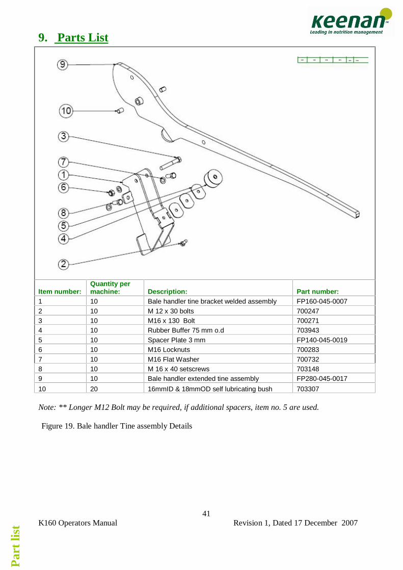
Note: ** Longer M12 Bolt may be required, if additional spacers, item no. 5 are used. Figure 19. Bale handler Tine assembly Details
Item number: Quantity per machine: Description: Part number:
1 10 Bale handler tine bracket welded assembly FP160-045-0007 2 10 M 12 x 30 bolts 700247 3 10 M16 x 130 Bolt 700271 4 10 Rubber Buffer 75 mm o.d 703943 5 10 Spacer Plate 3 mm FP140-045-0019 6 10 M16 Locknuts 700283 7 10 M16 Flat Washer 700732 8 10 M 16 x 40 setscrews 703148 9 10 Bale handler extended tine assembly FP280-045-0017
10 20 16mmID & 18mmOD self lubricating bush 703307
Par
t lis
t
K160 Operators Manual Revision 1, Dated 17 December 2007
42
10: TROUBLESHOOTING PROBLEM : SOLUTION: 1. Weighing display will not work properly Check section on weighing. 2. VFC door does not move Check hydraulic hoses and that valves are open.
Check tractor hydraulic oil level Check ram condition and pins are secure.
3. VFC door drops during mixing Insufficient hydraulic pressure � check spool
valve on tractor or fit non return valve in line. Check ram for signs of leakage.
4. Excessive shear bolt breakage Machine overloaded.
Driving chain too loose � check condition and adjust. Feed out too fast - open feed out door slowly at first then open fully. Turn paddle a few turns before opening the feed out door to avoid huge load on machine � especially after feed has settled in body of machine. Run machine slower. Never load bales directly down on paddle in one go - always chop up into at least 4 pieces.
5. Noisy operation Oil chains liberally - adjust tension on chains. Grease all nipples. Check chain alignment
6. Feed is not mixed properly. Insufficient mixing time.
Loading materials in wrong order Not enough time given for chopping. Overloading of machine.
7. Feed out is too slow. Check condition of paddle rubbers.
Slow down tractor ground speed. Reduce engine revs to give paddle more time to push material into auger.
8. Horsepower requirement is too high Check chopping blades and top knife for
sharpness. Machine overloaded.
K160 Operators Manual Revision 1, Dated 17 December 2007
43
9. Machine is not chopping Blades blunt. Not enough material in body - not heavy enough �Try adding more material or in case of hay/ straw add water or a fork of silage to weigh it down. Machine overloaded.
10: Machine breaks ASA160 Link Check chain alignment of large sprocket,
Tolerance +/- 2 mm. Check chamfer on edge. Check roll pins used in joiner link.
10. WEIGHING TROUBLESHOOTING Keenan troubleshooting tips on weighing If you experience problems in the operation of the Weighing System, read through this Troubleshooting section first before contacting KEENAN SERVICE. Reading Drifting If the reading on the Weigh Box is drifting or does not stay steady, the most likely cause of the problem is dampness/moisture in or around the weigh box or cables. Please follow these steps to locate and correct the problem.
Disconnect the cables on the weigh box. Ensure they are labelled correctly for reconnection. Check both the plug on the cable and the connector on the Weigh box for dampness and/or corrosion of the terminals. If any dampness is found dry it off thoroughly with a hair drier. If corrosion is found on the terminals then clean thoroughly. Reconnect cable and test.
Check for loose wiring or dampness. Some machines are fitted with a junction box. The
procedure as detailed above applies.
Check Weigh cell plugs for dampness and also check Weigh cell cables for any breaks and/or dampness.
If the above measures do not rectify the problem then contact KEENAN SERVICE for further assistance. System Weighing Inaccurately If you suspect that the system is weighing inaccurately, check all four weigh cells to make sure that they are mounted correctly. If the bolt through the weigh cell has come loose or broken, the weigh cell can turn upside-down resulting in that weigh cell giving an inaccurate reading. (As you face the back of the machine the cable should be to the Right Hand Side of each of the rear Weigh cells. As you face the front of the machine the cable should be to the Right Hand Side of each of the front Weigh cells.) If a Weigh cell is turned upside-down, remove the bolt (M20 on K 160) and turn the Weigh cell. To check that the system is weighing correctly, get some known weight (e.g. A bag of fertilizer) and place it on each corner of the machine in turn. You should get the same reading for each corner. If one corner returns a significantly different reading from the other three then this points to a faulty weigh cell on that corner.
Tro
uble
shoo
ting
K160 Operators Manual Revision 1, Dated 17 December 2007
44
Weigh box will not switch ON Check the power cable thoroughly and make certain that you are getting power from the tractor to the display. The fuse for the display is located inside the cabinet but do not disassemble display as to do so may cause serious damage. It is extremely rare for this fuse to be blown so if there is power feeding to the display and it is still not working contact your Keenan service agent. The fuse located at the bottom panel of the weigh box is for the external alarm and nothing to do with the display.
K160 Operators Manual Revision 1, Dated 17 December 2007
45
11. WARRANTY Richard Keenan & Co. Ltd. ("the Company") shall undertake to correct by repair or replacement only at the Company�s option, any defect of material or workmanship, which occurs in any of its products as listed herein within the following warranty period. This Warranty is for the benefit of the initial owner as notified to the Company. Standard Warranty period from date of commissioning is 12 months unless otherwise agreed in writing between the company and the owner. This Warranty shall cease to apply on any resale of the equipment by the initial owner. The Warranty shall not apply to: A Any machine used by a third party, who will not have had instruction in the correct use of the
machine by an official representative of the Company. B Any machine which has sustained damage through general wear and tear or neglect or use for
which the machines were not intended to be used by the Company. C Bearings, sprockets, chains and other wearing parts unless clear evidence of immediate
working failure which is directly attributable to such parts can be furnished. D Any consumable or perishable parts such as knives, blades, rubber seals, hydraulic components,
shear-bolts, brake liners, electric components and running gear, unless clear evidence of immediate working failure which is directly attributable to such parts can be furnished.
E Any machine on which the identification marks have been removed or altered. F Any machine that has not received effective routine maintenance using recommended Keenan
products as laid down in the operator�s manual. G Any machine that has received repairs or modifications by persons unauthorized by the
Company. H Any machine fitted with spurious or non-genuine spare parts and attachments, or spare parts or
attachments not approved by the Company. I Any machine damaged in transit whilst being loaded or unloaded on premises other than those
owned by the Company. J Parts which may be defective or which may have failed and which are not retained on site
pending further investigation by the Company. Such parts may need to be inspected in situ by a Company representative.
K Any machine damaged or any damage incurred prior to the machine being commissioned by an authorized representative of the Company.
The sole and exclusive claim against the Company made by the person specified above shall be for the repair or replacement of defective parts without prejudice to any rights pursuant to the Liability for Defective Products Act, 1991. No other claim, including, but not limited to, for incidental, direct or indirect or consequential damages or for lost profits, lost sales, lost business, lost savings, loss of goodwill or loss of reputation or any other loss of whatever nature however sustained shall be available. This Warranty constitutes the only warranty made by the Company and supersedes and overrides all oral and written statements or representations made by any Company representative or dealer or any other agreement, arrangement, practice, custom or understanding between the parties. Any claim under the Warranty must be promptly notified to the Company at the address on the invoice. In the event of the machine being loaned to or hired by a third party warranty cover is not transferable unless g iven in writing and signed by a Director of Richard Keenan & Co.
War
rant
y W
arra
nty
K160 Operators Manual Revision 1, Dated 17 December 2007
46
This Warranty shall be construed in accordance with Irish law and shall be subject to the exclusive jurisdiction of the Irish Courts. PRODUCT CHANGES AND IMPROVEMENTS Due to our policy of continuous improvement, Richard Keenan & Co. reserve the right to make changes in design, to add improvements or to otherwise modify any of its products without incurring any obligation on products previously supplied.
K160 Operators Manual Revision 1, Dated 17 December 2007
47
10. EC DECLARATION OF CONFORMITY EC Declaration of Conformity. In accordance with Directive 98/37/EC. Manufacturer: Richard Keenan & Co. Ltd., Borris, Co. Carlow, Ireland. Certifies that the Keenan K 160 complies with the essential safety requirements of the Directive 98/37/EC. To conform to these essential health and safety requirements, the provisions of the following harmonized standards were particularly considered. EN ISO 12100-1, EN ISO 12100-2, EN294, EN 1152, EN349, EN703, EN1553 (MRL app. IIA), ISO 11684, ISO 12140 Date: 29th August 2003 Signed: James Greene, Managing Director
K160 Operators Manual Revision 1, Dated 17 December 2007
48
Head Office Richard Keenan & Company Limited Borris, Co. Carlow, Ireland tel. +353 (0) 59 9771200 fax. +353 (0) 59 9771227 email: [email protected] website: www.keenansystem.com UK Office Richard Keenan (UK) Ltd 6th Street, National Agricultural Centre, Stoneleigh Park, Kenilworth, Warwickshire CV8 2RL, England. Tel. Administration: 024 766 98200 Fax: 024 766 98273 Nutrition Feedline: 024 76698270 24 hr Service: 024 766 90903 website: www.keenansystem.com Australia Office Keenan PTY 1/109 Breen Street Bendigo, Victoria, 3550, Australia. Tel: 0354 42 3333/1800 817207 Fax: 0354 41 3633 German Office Keenan GmbH, Postfach 1305, 48663 Ahaus, Germany. Tel: 02561 449380 Fax: 02561 4493858 Service Hotline: 0700 533 626 767 Service Office: 02561 449 380 email: [email protected] website: www.keenansystem.de French Office Keenan France SARL, Z.A. des Rolandières, Rue des Rolandières, 35120 Dol-de-Bretange, France. Tel. 0299 480254 Fax: 0299 480577 email: [email protected]
K160 Operators Manual Revision 1, Dated 17 December 2007
49
USA Office Keenan USA PO Box 7 PA 17309, USA. Toll Free: 1-800-710-5620 Service: Contact Keenan USA or call your local Keenan Dealer website: www.keenansystem.com


