KNX PL110/132 Energy Manager KNX powerline PL110/132 transceiver module www.keletron.com This document contains information on a new product. Specification and information herein are subject to change without notice. ■ Product summary Keletron KNX Powerline PL110/132 Energy Manager (KEM) - provides energy consumption measurements, load control, communication to a residential gateway over the powerline and a serial communication bridge to controlled devices. It can be engineered to be embedded inside OEM residential appliances. Our PL110/132 Energy Manager , is based on a KNX powerline transceiver module, controlled by Keletron Ltd – Tel. +30-2310-947979 Fax +30-2310-947386 Email:[email protected]Page 1
This document contains information on a new product. Specification and information herein are
subject to change without notice.
■ Product summary
Keletron KNX Powerline PL110/132 Energy Manager (KEM) - provides energy consumption measurements, load control, communication to a residential gateway over the powerline and a serial communication bridge to controlled devices. It can be engineered to be embedded inside OEM residential appliances.
Our PL110/132 Energy Manager , is based on a KNX powerline transceiver module, controlled by
a PIC 18F6722; implementing an OSI7 PL110/132 KNX stack protocol as defined by the KNX Association (www.knx.org). Supporting powerline modem used is ST7540. Our hardware modules avail a UART interface for serial communication, configuration and firmware update. They can be engineered to communicate with a wide variety of sensors and actuators; and have inbuilt energy metering modules.
KEM meets the KNX PL specification and can be configured to operate in the KNX S, A and E modes, while adhering to the 110 kHz or 132.5 kHz frequency band. The physical layer complies to the relevant parts of the CENELEC EN 50090. Also available is Linux based software, which controls this device, exposing an XML web based interface.
■ Application space
• Home and building control • HVAC • Electrical load control • Energy management
■ Basic Features of KEM
• KNX PL110 or PL132 compliant• Powerline Carrier Modem 50 Hz/220 V mains• Carrier Frequency 110 kHz/132.5 kHz• 1200 or 2400 bps over powerline• Half duplex• High sensitivity (0.25 mV RMS)• CRC and FEC error correction• PIC 18F6722 core, ST 7540 powerline modem• 128 kBytes internal flash memory• Auto boot-loading Program from serial flash• In-circuit serial flash programming• UART accessible firmware update• AD/DAC capability to interface with external devices• Buffered SPI to external energy metering IC• Power Supply 5.0 V• Electrical Load isolation• Ambient Temperature Range: -40 °C to +85 °C• Linux compatible residential gateway software• Bridge connectivity to ZigBee or other supported protocols via gateway
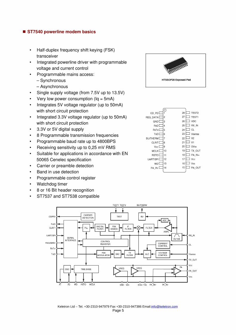
• Single supply voltage (from 7.5V up to 13.5V)• Very low power consumption (Iq = 5mA)• Integrates 5V voltage regulator (up to 50mA)
with short circuit protection• Integrated 3.3V voltage regulator (up to 50mA)
with short circuit protection• 3.3V or 5V digital supply• 8 Programmable transmission frequencies• Programmable baud rate up to 4800BPS• Receiving sensitivity up to 0,25 mV RMS• Suitable for applications in accordance with EN
50065 Cenelec specification• Carrier or preamble detection• Band in use detection• Programmable control register• Watchdog timer• 8 or 16 Bit header recognition• ST7537 and ST7538 compatible
KNX is an open European standardized protocol, used by manufacturers of electronic automation devices to communicate information among their devices either using twisted pair wires, RF trans-mission, or powerline communication. Keletron Energy Manager adheres to KNX powerline proto-cols PL110 and PL132.
KNX PL132 supports communications at rates of up-to 2400 bps between KNX devices sharing a common powerline, whereas PL110 reaches 1200 bps. PL110 and PL132 are low bandwidth pro-tocols; noise-resistant and excellent for communicating control signals over the powerlines -- on quite long distances, which can reach several hundred meters.
Digital signals modulation techniques over powerline signal
■ CDMA access to the KNX powerline bus
The network topology of KEM is based on a common access powerline bus. Only one KEM device on the net can use the bus at any given moment. All the other connected devices ‘listen’ to the bus traffic, and wait to find an ‘empty slot’ on the bus to transmit their information. The technology used is ‘Carrier Detect Multiple Access, Collision Avoidance’ (CDMA-CA). Since PL110 and PL132 are low bandwidth communication protocols, they were designed to support both a peer-to-peer and multi-cast communications to conserve precious bandwidth.
KEM implements a KNX PL110/PL132 network communication stack. The words ‘Network Stack’ indicate an ubiquitous OSI-7 stack. Indeed, KNX PL110/132 specifies 5 out of the 7 OSI network layers, namely Physical, Data link, Network, Transport and Application. Session and Presentation layers are not defined, and are thus considered transparent to their adjacent layers.
KNX defines 2 additional stack sub-categories, the router stack and the bridge stack. Standardized PL110/132 KNX routers and bridges are available from several vendors.
The reader should note that the KNX protocol, thus also KEM, is layer flexible. It allows the KNX developer to turn stack layers on or off (starting from the top and moving downwards) up-to the data link layer. A full PL110/PL132 device stack implementation can be expected to be hosted in 70 kbytes of flash space on a 16-bit micro-processor base, including support for network manage-ment procedures and KNX net topology administration. Our hardware is also equipped with 1Kbyte of EEPROM which is used to store persistent KNX data (e.g. KNX network address ID, network groups, KNX Object attributes etc).
■ KEM hardware base
Our KEM is a hardware design, based on the Microchip PIC18F6722 micro-controller and the ST7540 powerline modem chip. The PIC processor contains the necessary code to implement a full OSI7 KNX protocol stack; it performs real time operations to control the waveform powerline signal generation of the ST7540 modem, and handles all communication requests from external devices. There are two additional hardware components, which are integrated in a KEM: an Allegro Current metering chip and a TRIAC module for electrical load control, although we can deliver customized KEMs connected to any type of sensor or actuator our clients demand.
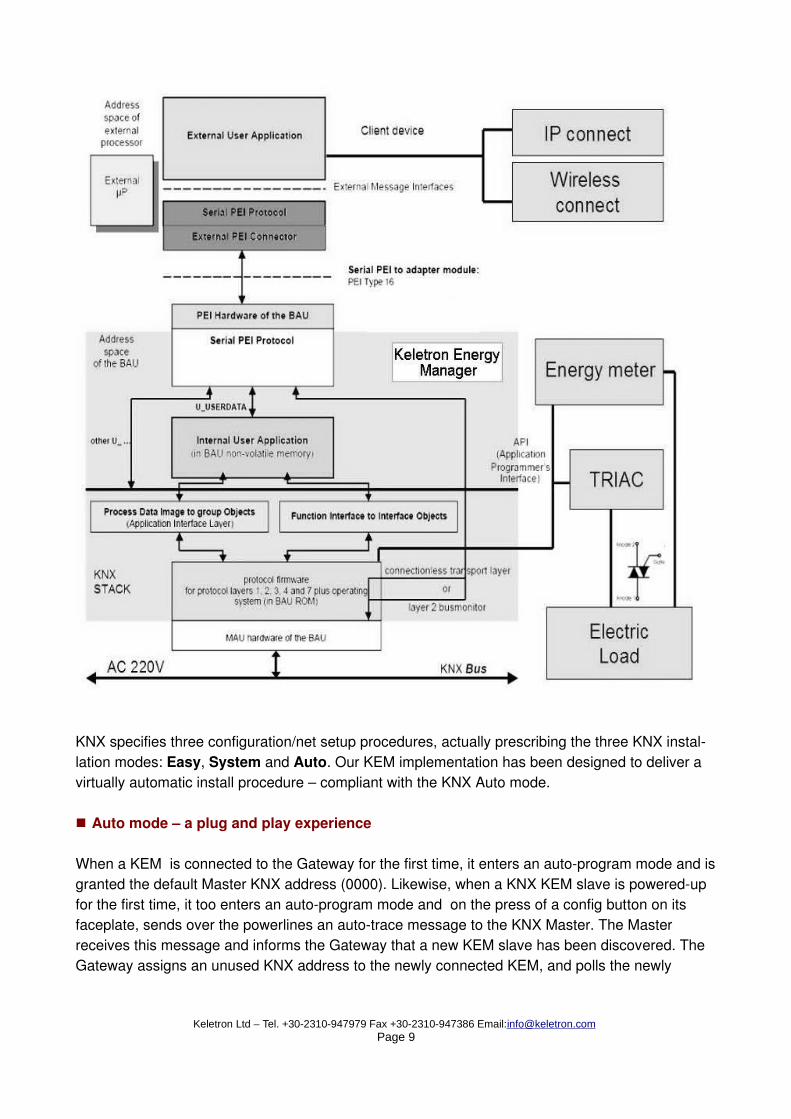
KNX specifies three configuration/net setup procedures, actually prescribing the three KNX instal-lation modes: Easy, System and Auto. Our KEM implementation has been designed to deliver a virtually automatic install procedure – compliant with the KNX Auto mode.
■ Auto mode – a plug and play experience
When a KEM is connected to the Gateway for the first time, it enters an auto-program mode and is granted the default Master KNX address (0000). Likewise, when a KNX KEM slave is powered-up for the first time, it too enters an auto-program mode and on the press of a config button on its faceplate, sends over the powerlines an auto-trace message to the KNX Master. The Master receives this message and informs the Gateway that a new KEM slave has been discovered. The Gateway assigns an unused KNX address to the newly connected KEM, and polls the newly
connected device for KNX identity and type attributes.
The KNX KEM is able to parse user data into KNX group object data (KNX standardized com-mands, aimed at multiple recipients on the KNX net or specific KNX Functional Blocks) – and KNX interface objects, working as conceptual information conduits/links between KNX devices and sen-sors. This virtual linking phase is automatically handled during the net setup phase.
■ Communication
KEM is a fully fledged KNX device, which can receive commands not only through the powerline, but also through a serial interface (RS232). This interface is called PEI (Peripheral External In-terface), and is the means through which a KEM can be connected to a PC or other type of device.
Our particular implementation uses PEI type 16, according to the KNX specification. KEMs sup-porting PEI10/FT1.2 can be delivered on request. The PEI is also the path through which we can submit bridge commands to KEM connected electrical devices that avail a serial port, like latest generation washing machines/ovens/fridges.
The KEM firmware■
The basic development steps that the KEM KNX firmware encompassed were the following:
Abstracted KNX stack design We designed our KNX firmware framework, in such a way, as to facilitate future porting to new processing platforms and microprocessors.
Generic finite state machine for KNX stack layers design Each KNX stack layer is a layered finite state machine/parser. We use 4 of these structures, for the Data link, Network, Transport and Application layer, respectively.
KNX internal message pump in conjunction with a finite state machine The Transport and Application layers use an event handler on-top of their finite state machines. Their defined behavior is quite complex and dependent on the device’s functionality state (idle, working, receiving information, etc).
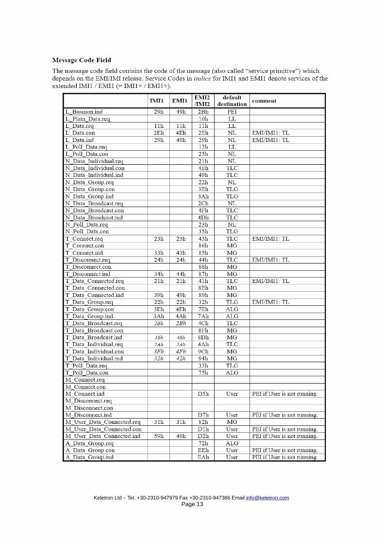
EMI/IMI parameter parser for each KNX layer There is a clearly defined interface for communicating information within the KNX stack. When commands reach the stack via the PEI16 , the commands are coded in EMI (KNX External Mes-sage Interface) format. These commands are internally translated into IMI (KNX Internal Message Interface), which actually control the information flow among the KNX stack layers.
PEI16 protocol implementation The PEI16 protocol is defined both physically (electrical signal-wise) as well as abstractly by the KNX specs. It is conceptually a set of control codes communicated over RS232 between an exter-
nal control terminal (eg Gateway) and the KEM. A KEM with PEI 10 FT1.2 can be delivered on request.
EEPROM and KNX Virtual RAM interface engineering Since KNX is an open standard, (thus hardware platform independent), no actual KNX hardware specs are provided. Instead, on all hardware related functions, the specs define abstracted functions. These are translated into concrete ones by the specific KNX PL implementation. Thus, we define virtual access points for the particular micro-processor base we are using. There is an area in the RAM which is used to store the KNX object RAM data – which means that a Virtual RAM interface has been incorporated in the stack, to access this area in a uniform and KNX compliant manner.
KNX API implementation The KNX API is a set of functions that the KNX micro-processor must implement in order to be able to process KNX messages. It is the standard function library of the KNX micro-processor world, irrespective of hardware base chosen.
KNX Object Attribute Translator In KNX topologies, the KNX net is used to communicate information between logical entities, called functional blocks, which are atomic operators in a KNX system (like an actuator, a push button or a sensor). All these come in predefined types, with standardized inputs and outputs. This format is parsed both at the broadcast (message formulation) and the reception end; which is what the KEM object attribute translator does.
Implementation of KNX net setup message parser This is a message conduit, aimed to ‘personalize’ the KNX device, by auto-registering its identity. The messages that are processed, interact with the KNX Bus Access Unit's EEPROM, by reading/ writing or altering its contents. Testing and Simulation in vitro The KNX firmware codebase was unit and simulation tested before being ported into a micro-pro-cessor. It is immune to buffer overruns, does not use dynamic memory allocation – de-allocation techniques for speed and stability – it is crash immune under any KNX traffic load, and it is tracked by a watch dog. Since the KNX stack is a real-time system it was critical to verify that all atomic op-erations were executing in proper time frames, compatible with the KNX stack communication speed requests.
Internal interfaces are used when the KEM system is integrated to a another device (e.g KNX hardware integrated inside a residential appliance, like a washing machine). In simple configura-tions, the KEM firmware can be hosted inside the residential device’s microprocessor, or may be hosted on a dual processor architecture, with one microprocessor controlling the residential device and the other implementing the KEM KNX functions. Either way, there are standard messages exchanged inside the compound KEM and residential device hardware, which adhere to the KNX specification IMI1.0 (Internal Message interface) protocol. Moreover, there are numerous service primitives that are communicated inside the KNX stack, when information flows from the physical to the application layer and vice versa.
■ Serial interface specification
A KEM operates in either Master or Slave configuration. The Master KEM is connected to the Keletron Residential Gateway using a RS232 (9600N81)serial connection. A KEM Slave communicates with the Master using KNX powerline communication.
Our implementation of RS232 communication between gateway and KEM master is fully com-patible to the KNX EMI1 protocol (KNX KNX 03_06_03 EMI_IMI v1.0 AS). Keletron Gateway and KEM Master communicate using an exchange of data packets in the following format:
KNX EMI1 offers a collection of around 30 KNX command primitives, which can deliver a wide range of KNX services.
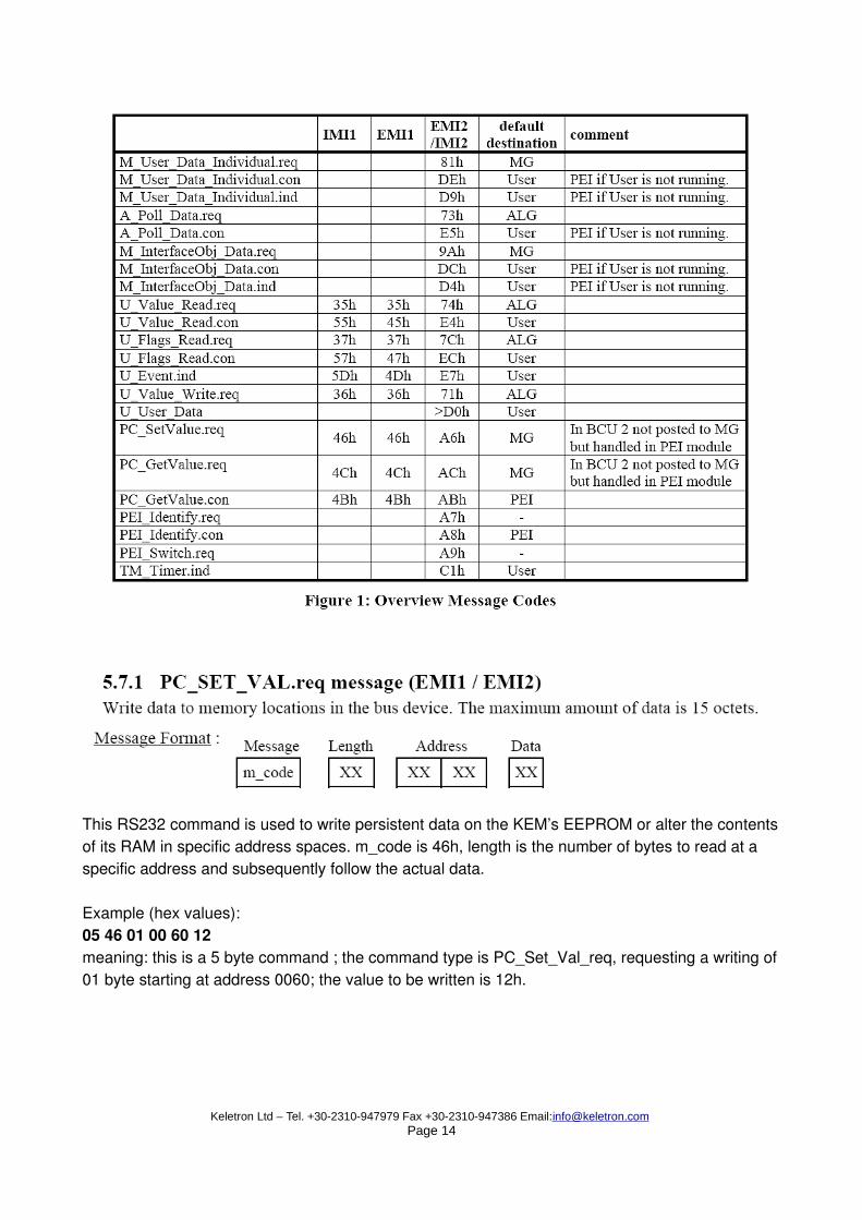
This RS232 command is used to write persistent data on the KEM’s EEPROM or alter the contents of its RAM in specific address spaces. m_code is 46h, length is the number of bytes to read at a specific address and subsequently follow the actual data.
Example (hex values): 05 46 01 00 60 12 meaning: this is a 5 byte command ; the command type is PC_Set_Val_req, requesting a writing of 01 byte starting at address 0060; the value to be written is 12h.
This RS232 command is used to read persistent data on the KEM’s EEPROM or contents on its RAM. m_code is 4Ch, length is the number of bytes to read at a specific address. Example (hex values): 04 4C 01 00 60 meaning: a 4 byte command length, command type is PC_Get_Val_req, requesting a reading of 01 byte starting at memory address 0060.
This RS232 command is sent by an KEM in response to PC_GET_VAL.req and contains the re-quested data red from the KEM’s RAM or EEPROM memory space.
This is the most important KNX command, used to send a data packages (or frames) from the Master KEM to one or more KEM slaves over the powerlines and vice versa.
The m_code is 11h. The control field dictates the broadcast priority and the recipient acknowledgement request, the frame’s destination address; the frame type (group or individual) and the hop count,(or number of KNX routers the frame can hop-over when travelling on the pow-erline net). NPDU contains the useful command data, like requesting a slave KEM’s TRIAC on /off, or an electrical current measurement. The KEM NPDU field likewise is listed as follows: 02 f7 00 : KEM electrical load switch off 02 f7 01 : KEM electrical load switch on 02 f7 02 : KEM request electrical current measurement (Irms in Amps). The NPDU format is fully compliant to the KNX application command tags, which are also hosted inside this field. Using a destination address of 0000 makes the frame global-cast to all Slave KEMs connected on the system topology.
Example A switch on load command aimed at Slave KEM hosted in address 0100: 0a 11 00 0000 0100 62 02 f7 01
Example B switch off load command aimed at Slave KEM hosted in address 0100: 0a 11 00 00 00 01 00 62 02 f7 00
Example C request electrical current command from Slave KEM hosted at address 0100: 0a 11 00 00 00 01 00 62 02 f7 02
A response reaching the Master from the powerline KNX bus contains a 16bit Irms (Electrical cur-rent) measurement, taken from the controlled device attached to the KEM Slave. This information is collected by the KEM Master, and is communicated to the Gateway, where it is processed to complete the energy management loop.
Residential Gateway■
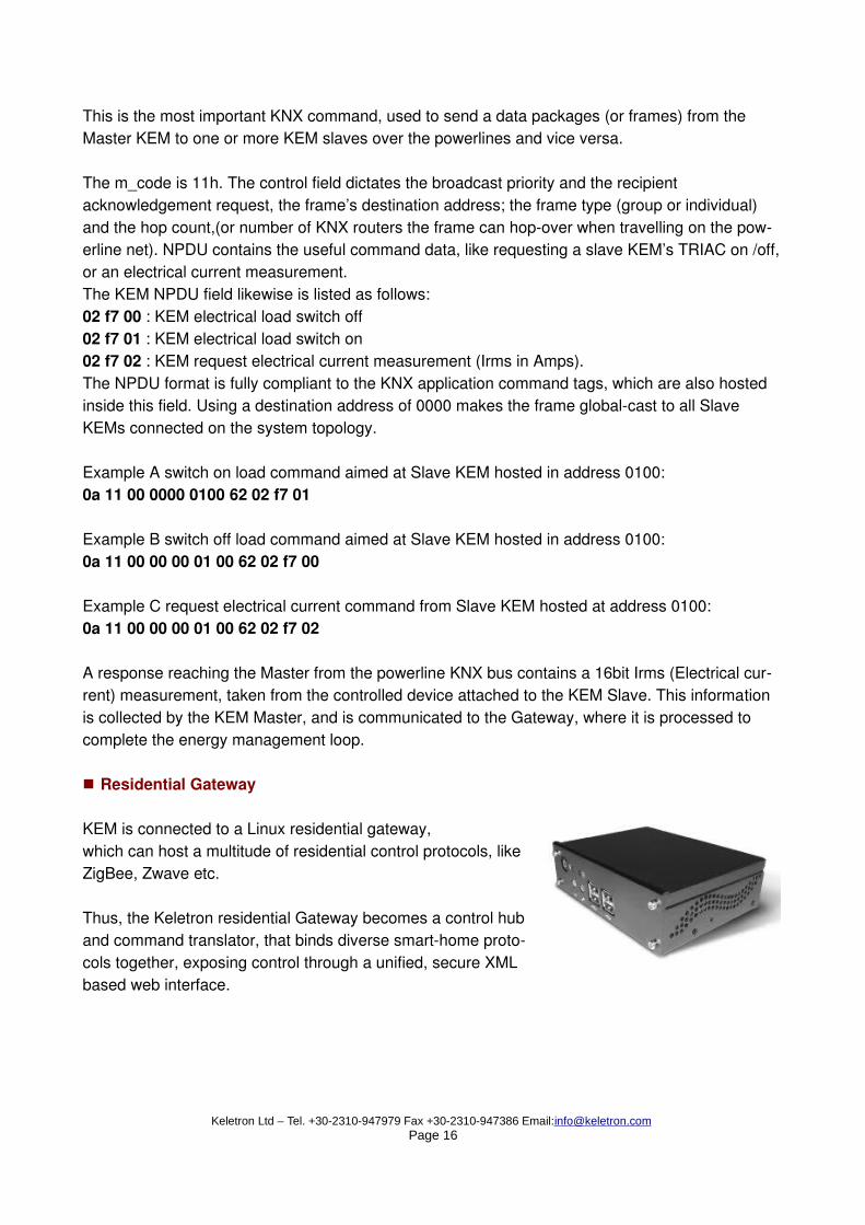
KEM is connected to a Linux residential gateway,which can host a multitude of residential control protocols, like ZigBee, Zwave etc.
Thus, the Keletron residential Gateway becomes a control hub and command translator, that binds diverse smart-home proto-cols together, exposing control through a unified, secure XML based web interface.


![KNX Association KNX Association [Official website]...KNX BBegeHMe CTaHOBRCb KNX-napTHep0M, Bbl, KaK BaHHblü KNX-HHcTaM9Top, noAHhMaeTe ce6q M CBC»O Ha KaqeCTBeHH0 ypogeHb - o Bac](https://static.documents.pub/doc/80x56/5f5ce7fd12687c638d19b258/knx-association-knx-association-official-website-knx-bbegehme-ctahobrcb-knx-napthep0m.jpg)


