14
1 UC Berkeley Ken Youssefi Electrical Drawings
| Date post: | 24-Dec-2015 |
| Category: |
Documents |
| Upload: | anastasia-green |
| View: | 222 times |
| Download: | 3 times |
1 UC Berkeley Ken Youssefi
Electrical Drawings
Ken Youssefi UC Berkeley 2
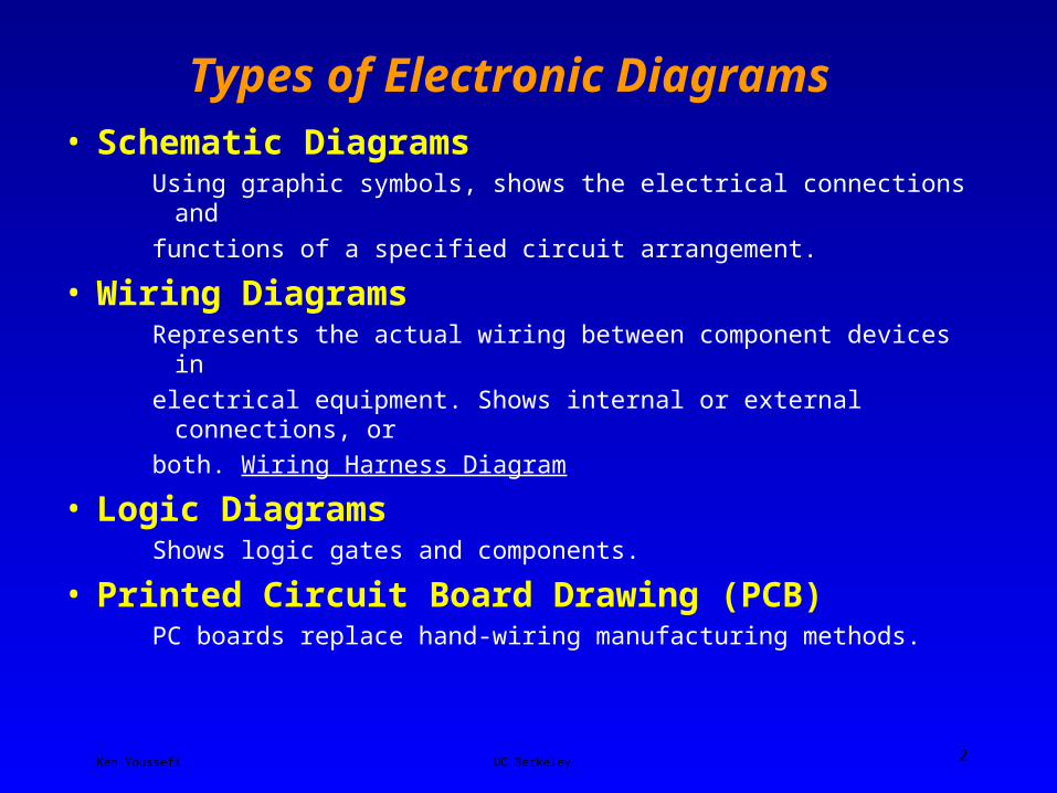
Types of Electronic Diagrams • Schematic Diagrams
Using graphic symbols, shows the electrical connections and
functions of a specified circuit arrangement.
• Wiring DiagramsRepresents the actual wiring between component devices in
electrical equipment. Shows internal or external connections, or
both. Wiring Harness Diagram
• Logic DiagramsShows logic gates and components.
• Printed Circuit Board Drawing (PCB)PC boards replace hand-wiring manufacturing methods.

Ken Youssefi UC Berkeley 3
Schematic Drawings
Ken Youssefi UC Berkeley 4
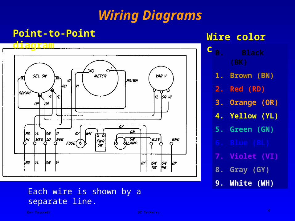
Wiring DiagramsPoint-to-Point diagram Wire color codes
0. Black (BK)
1. Brown (BN)
2. Red (RD)
3. Orange (OR)
4. Yellow (YL)
5. Green (GN)
6. Blue (BL)
7. Violet (VI)
8. Gray (GY)
9. White (WH)
Each wire is shown by a separate line.
Ken Youssefi UC Berkeley 5
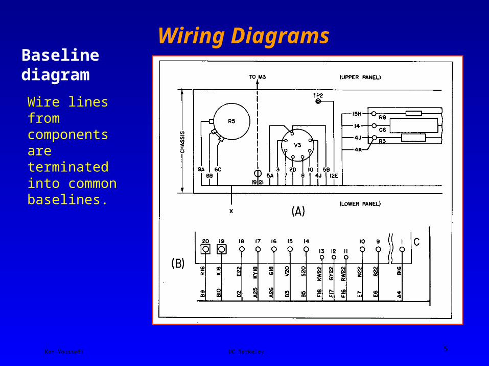
Wiring DiagramsBaseline diagram
Wire lines from components are terminated into common baselines.
Ken Youssefi UC Berkeley 6
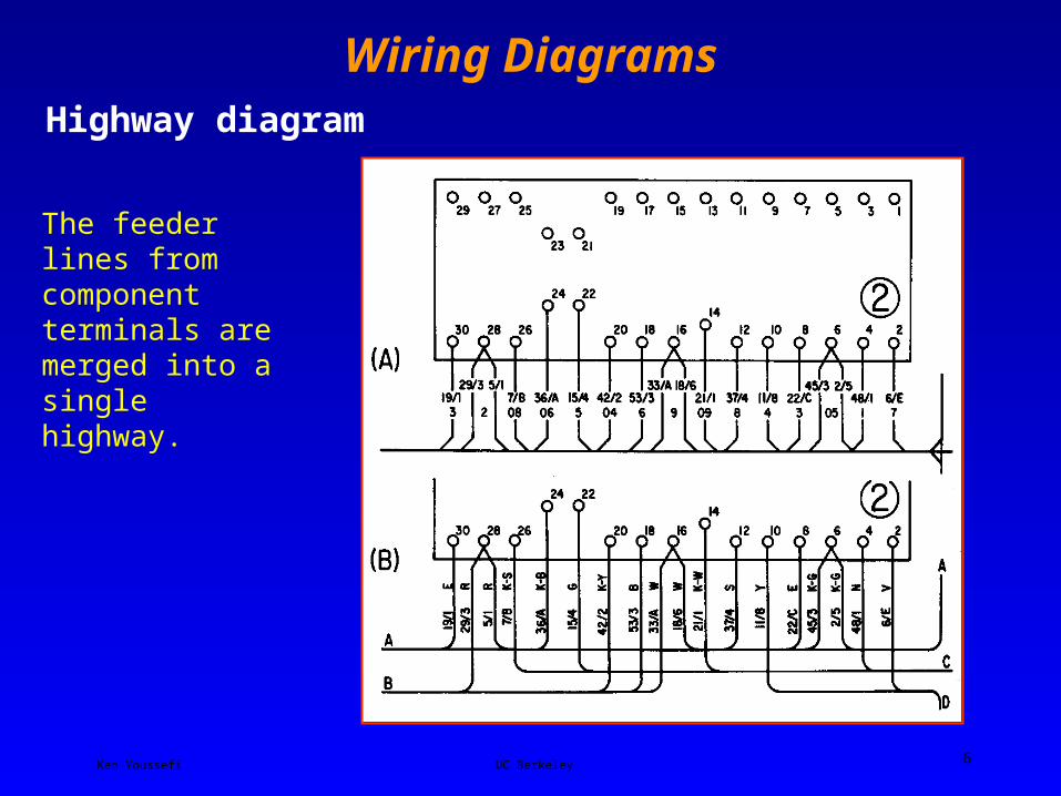
Wiring DiagramsHighway diagram
The feeder lines from component terminals are merged into a single highway.
Ken Youssefi UC Berkeley 7
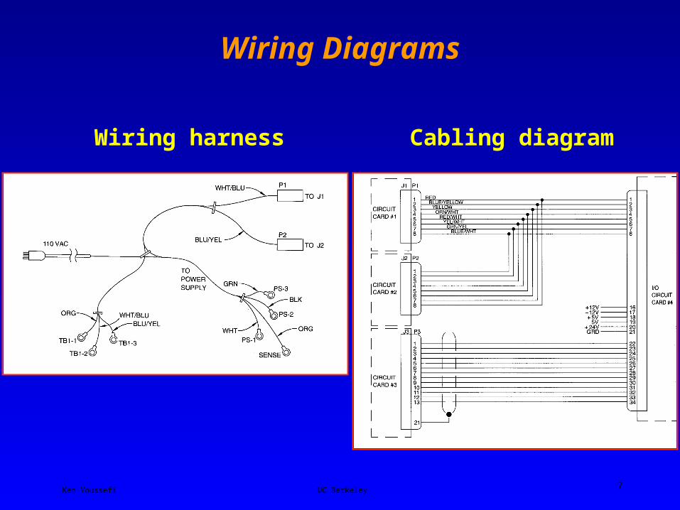
Wiring Diagrams
Wiring harness Cabling diagram
Ken Youssefi UC Berkeley 8
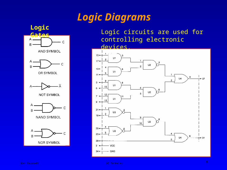
Logic DiagramsLogic Gates
Logic circuits are used for controlling electronic devices.

Ken Youssefi UC Berkeley 9
Printed Circuit Board Drawings (PCBs) Schematic Drawing Provides the basis of a circuit board. Logic diagram is used for
integrated circuits.
Artwork Drawing – Component side Artwork drawings are used to create the mask that will actually create the
etched circuit. The component side artwork shows the circuitry that will be
etched on the same side as the circuit components.
Ken Youssefi UC Berkeley 10
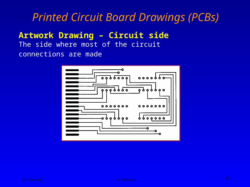
Printed Circuit Board Drawings (PCBs)
Artwork Drawing – Circuit side
The side where most of the circuit connections are made
Ken Youssefi UC Berkeley 11
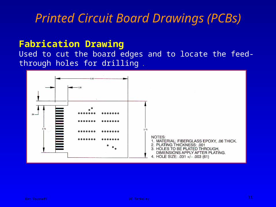
Printed Circuit Board Drawings (PCBs)
Fabrication DrawingUsed to cut the board edges and to locate the feed-through holes for drilling .

Ken Youssefi UC Berkeley 12
Printed Circuit Board Drawings (PCBs)
Silkscreen DrawingLettering and component outlines are
printed on the board.
Assembly DrawingShows how components are mounted before being soldered, and it is used by manufacturing to ensure proper assembly of the
components.

Ken Youssefi UC Berkeley 13
Printed Circuit Board Drawings (PCBs)
Ken Youssefi UC Berkeley 14
Sources of Standardized Codes and Symbols • ANSI - American National Standards Institute - Graphic Symbols for
Electrical and Electronic Diagrams - ANSI / IEEE• Government standard for military contractors
MIL - STD – 275 Printed Wiring for Electronic Equipment
MIL - STD – 429 Printed Wiring and Printed Circuits –Terms and Definitions
MIL - STD – 454 Standard General Requirements for Electronic EquipmentMIL - STD – 681 Identification Coding and Application of
Hook Up and Lead WireMIL - STD – 1495 Multi-layer Printed Wiring Boards for
Electronic Equipment
• Underwriters’ Laboratory (UL) - Safety codes & consideration


