TI Designs: Reference DesignsKeyboard Controller using MSP430
TI DesignsTI Designs provide the foundation that you needincluding methodology, testing and design files toquickly evaluate and customize and system. TIDesigns help you accelerate your time to market.
An IMPORTANT NOTICE at the end of this TI reference design addresses authorized use, intellectual property matters and otherimportant disclaimers and information.
1 System DescriptionThis reference design describes the implementation of a keyboard controller with the followingcharacteristics:• Supports standard matrix keyboards: this design shows an implementation using a 15x8 matrix but
different keyboard layouts can be used• Independent of the communication interface: examples for USB and I2C are included• HID compliant: can interface directly with PC using USB or HID Over I2C.• “Ghost” key handling in software: prevents incorrect key detection from multiple simultaneous key
presses• HID boot protocol support: allows keyboard to be used to interface with a PC’s BIOS• Supports multimedia keys: common multimedia and power keys are implemented• Low power consumption: device goes to low power mode when idle• Composite USB device: an HID-datapipe back-channel is implemented to send custom data to the PC• Can be implemented in practically any MSP430 platform: examples for MSP430F5529 and
MSP430G2744 are included
1.1 MSP430 Family of MicrocontrollersThe Texas Instruments MSP430 family of ultra-low-power microcontrollers consists of several devicesfeaturing different sets of peripherals targeted for various applications. The architecture, combined withextensive low-power modes, is optimized to achieve extended battery life in portable measurementapplications. The device features a powerful 16-bit RISC CPU, 16-bit registers, and constant generatorsthat contribute to maximum code efficiency.
The software included in the design can be migrated to practically any MSP430 with enough GPIOs, butthe available examples are implemented for MSP430F5529 and MSP430G2744.
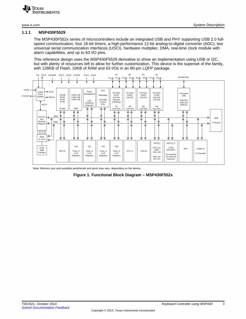
1.1.1 MSP430F5529The MSP430F552x series of microcontrollers include an integrated USB and PHY supporting USB 2.0 full-speed communication, four 16-bit timers, a high-performance 12-bit analog-to-digital converter (ADC), twouniversal serial communication interfaces (USCI), hardware multiplier, DMA, real-time clock module withalarm capabilities, and up to 63 I/O pins.
This reference design uses the MSP430F5529 derivative to show an implementation using USB or I2C,but with plenty of resources left to allow for further customization. This device is the superset of the family,with 128KB of Flash, 10KB of RAM and 63 I/Os in an 80-pin LQFP package.
1.1.2 MSP430G2744The MSP430G2x44 series is an ultra-low-power mixed signal microcontroller with two built-in 16-bit timers,a universal serial communication interface (USCI), 10-bit analog-to-digital converter (ADC) with integratedreference and data transfer controller (DTC), and up to 32 I/O pins. Typical application include sensorsystems that capture analog signals, convert them to digital values, and then process the data for displayor for transmission to a host system. Stand-alone radio-frequency (RF) sensor front ends are another areaof application.
This reference design also uses the MSP430G2744 to show an I2C implementation using a smallerdevice from the value-line family of MSP430 microcontrollers. This device is the superset of theMSP430G2x44 family with 32KB of Flash, 1KB of RAM and is available in 40-QFN, 38-TSSOP and theultra-small 49-DSBGA package for space constrained application.
Although this implementation is more limited in resources, some pins and enough memory is available forfurther customization.
1.2 TPS73533The TPS735xx family of low-dropout (LDO), low-power linear regulators offers excellent AC performancewith very low ground current. High power-supply rejection ratio (PSRR), low noise, fast start-up, andexcellent line and load transient response are provided while consuming a very low 46µA (typical) groundcurrent. The TPS735xx is stable with ceramic capacitors and uses an advanced BiCMOS fabricationprocess to yield a typical dropout voltage of 250mV at 500mA output. The TPS735xx uses a precisionvoltage reference and feedback loop to achieve overall accuracy of 2% (VOUT > 2.2V) over all load, line,process, and temperature variations. It is fully specified from TJ = –40°C to +125°C and is offered in low-profile, 2mm × 2mm SON and 3mm × 3mm SON packages that are ideal for wireless handsets, printers,and WLAN cards.
This reference design uses the TPS73533 regulator to convert 5V from USB to 3.3V used by the MSP430microcontrollers.
3.1 Key MatrixThe keyboard controller presented in this document implements a key matrix of rows and columns similarto smaller keypads like the one shown in the application report Implementing An Ultralow-Power KeypadInterface with MSP430 (SLAA139).
The implementation shown uses a 15 rows x 8 column matrix, which allows up to 120 keys, but it onlyuses 84 keys in total.
The key matrix used implemented in this example is shown in Figure 5.
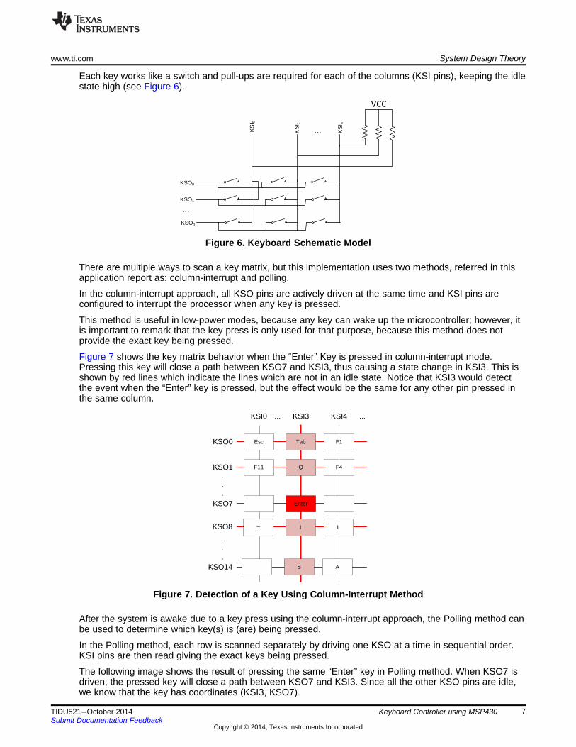
Each key works like a switch and pull-ups are required for each of the columns (KSI pins), keeping the idlestate high (see Figure 6).
Figure 6. Keyboard Schematic Model
There are multiple ways to scan a key matrix, but this implementation uses two methods, referred in thisapplication report as: column-interrupt and polling.
In the column-interrupt approach, all KSO pins are actively driven at the same time and KSI pins areconfigured to interrupt the processor when any key is pressed.
This method is useful in low-power modes, because any key can wake up the microcontroller; however, itis important to remark that the key press is only used for that purpose, because this method does notprovide the exact key being pressed.
Figure 7 shows the key matrix behavior when the “Enter” Key is pressed in column-interrupt mode.Pressing this key will close a path between KSO7 and KSI3, thus causing a state change in KSI3. This isshown by red lines which indicate the lines which are not in an idle state. Notice that KSI3 would detectthe event when the “Enter” key is pressed, but the effect would be the same for any other pin pressed inthe same column.
Figure 7. Detection of a Key Using Column-Interrupt Method
After the system is awake due to a key press using the column-interrupt approach, the Polling method canbe used to determine which key(s) is (are) being pressed.
In the Polling method, each row is scanned separately by driving one KSO at a time in sequential order.KSI pins are then read giving the exact keys being pressed.
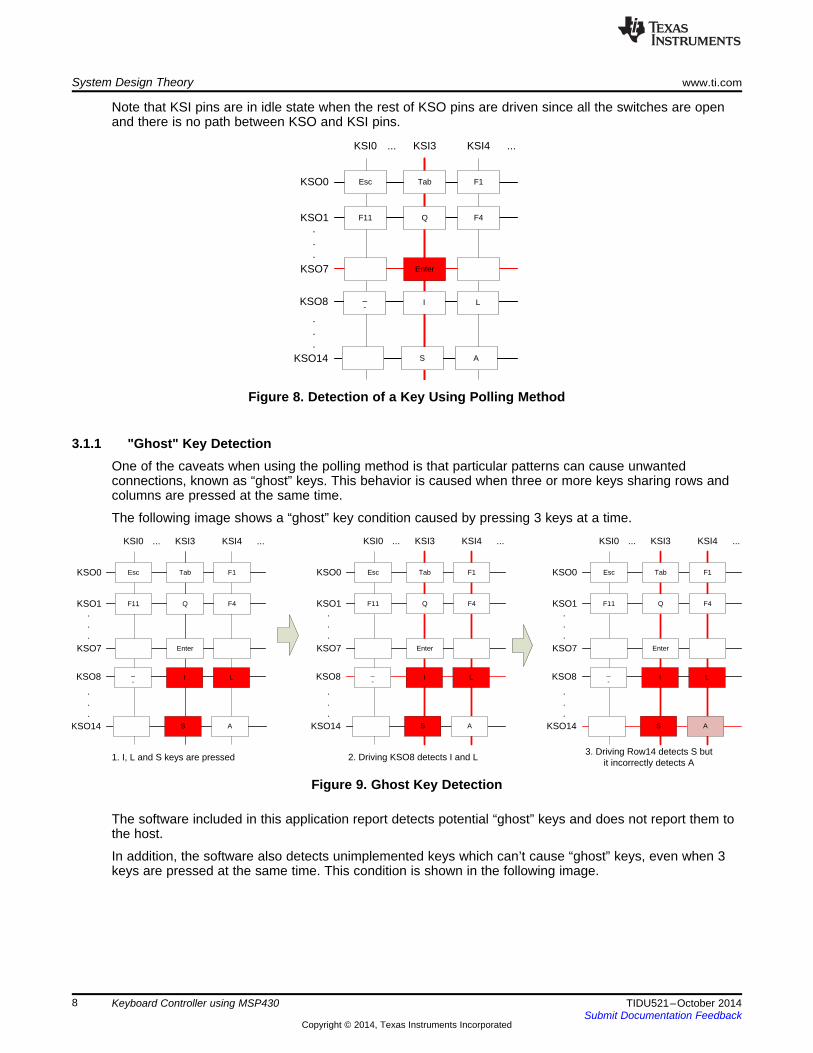
The following image shows the result of pressing the same “Enter” key in Polling method. When KSO7 isdriven, the pressed key will close a path between KSO7 and KSI3. Since all the other KSO pins are idle,we know that the key has coordinates (KSI3, KSO7).
Note that KSI pins are in idle state when the rest of KSO pins are driven since all the switches are openand there is no path between KSO and KSI pins.
Figure 8. Detection of a Key Using Polling Method
3.1.1 "Ghost" Key DetectionOne of the caveats when using the polling method is that particular patterns can cause unwantedconnections, known as “ghost” keys. This behavior is caused when three or more keys sharing rows andcolumns are pressed at the same time.
The following image shows a “ghost” key condition caused by pressing 3 keys at a time.
Figure 9. Ghost Key Detection
The software included in this application report detects potential “ghost” keys and does not report them tothe host.
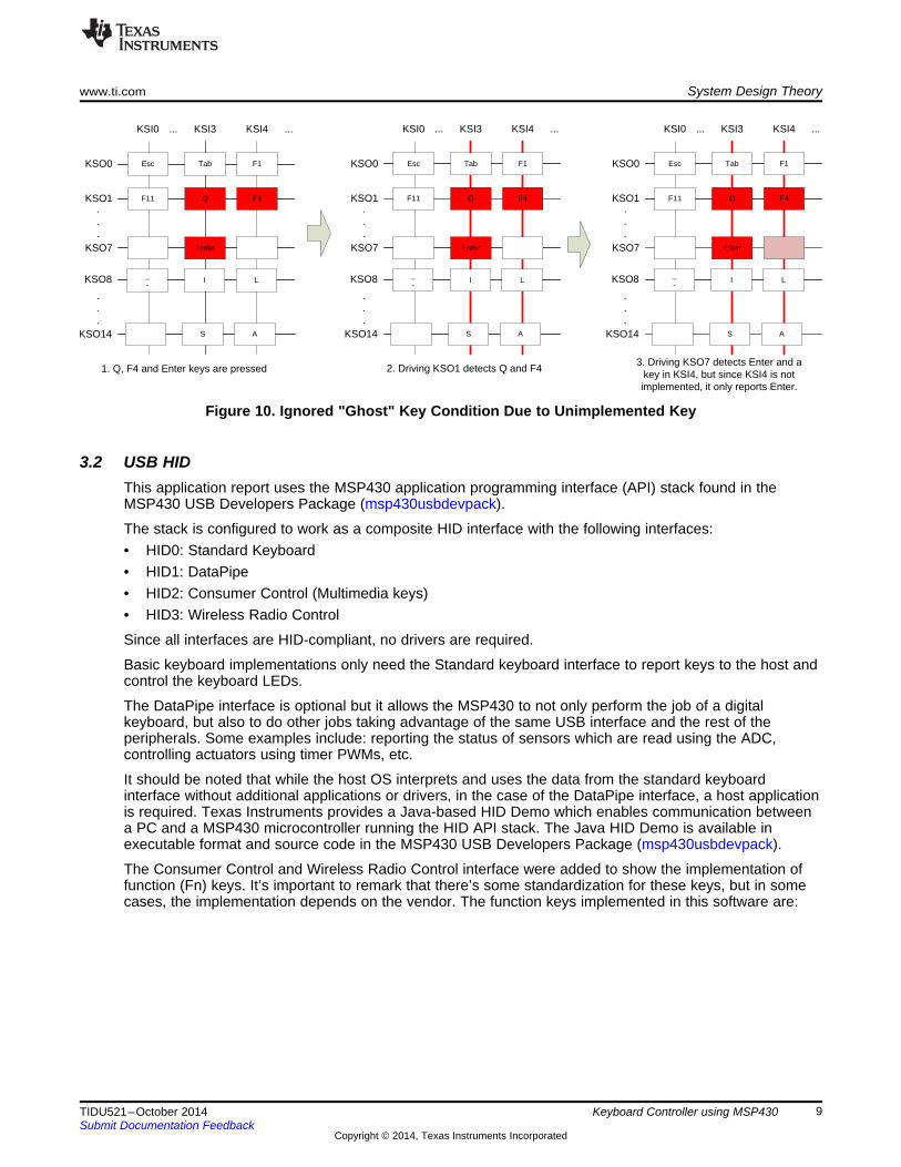
In addition, the software also detects unimplemented keys which can’t cause “ghost” keys, even when 3keys are pressed at the same time. This condition is shown in the following image.
Figure 10. Ignored "Ghost" Key Condition Due to Unimplemented Key
3.2 USB HIDThis application report uses the MSP430 application programming interface (API) stack found in theMSP430 USB Developers Package (msp430usbdevpack).
The stack is configured to work as a composite HID interface with the following interfaces:• HID0: Standard Keyboard• HID1: DataPipe• HID2: Consumer Control (Multimedia keys)• HID3: Wireless Radio Control
Since all interfaces are HID-compliant, no drivers are required.
Basic keyboard implementations only need the Standard keyboard interface to report keys to the host andcontrol the keyboard LEDs.
The DataPipe interface is optional but it allows the MSP430 to not only perform the job of a digitalkeyboard, but also to do other jobs taking advantage of the same USB interface and the rest of theperipherals. Some examples include: reporting the status of sensors which are read using the ADC,controlling actuators using timer PWMs, etc.
It should be noted that while the host OS interprets and uses the data from the standard keyboardinterface without additional applications or drivers, in the case of the DataPipe interface, a host applicationis required. Texas Instruments provides a Java-based HID Demo which enables communication betweena PC and a MSP430 microcontroller running the HID API stack. The Java HID Demo is available inexecutable format and source code in the MSP430 USB Developers Package (msp430usbdevpack).
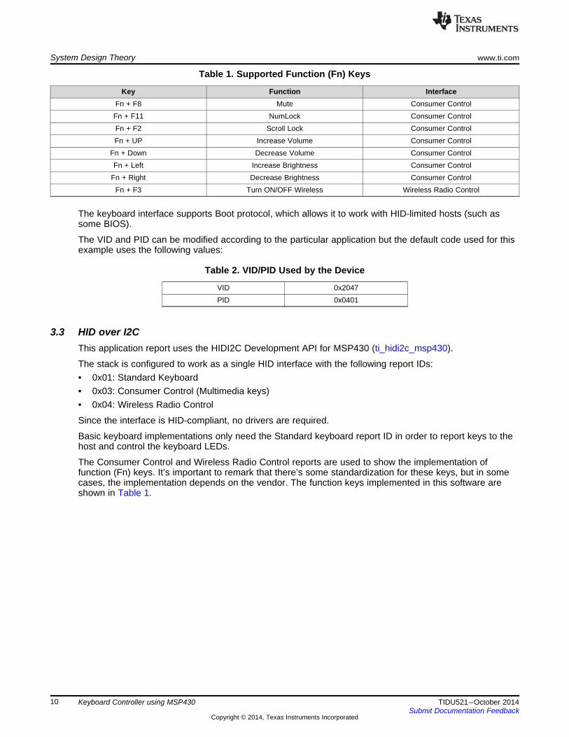
The Consumer Control and Wireless Radio Control interface were added to show the implementation offunction (Fn) keys. It’s important to remark that there’s some standardization for these keys, but in somecases, the implementation depends on the vendor. The function keys implemented in this software are:
Key Function InterfaceFn + F8 Mute Consumer ControlFn + F11 NumLock Consumer ControlFn + F2 Scroll Lock Consumer ControlFn + UP Increase Volume Consumer Control
Fn + Down Decrease Volume Consumer ControlFn + Left Increase Brightness Consumer Control
Fn + Right Decrease Brightness Consumer ControlFn + F3 Turn ON/OFF Wireless Wireless Radio Control
The keyboard interface supports Boot protocol, which allows it to work with HID-limited hosts (such assome BIOS).
The VID and PID can be modified according to the particular application but the default code used for thisexample uses the following values:
Table 2. VID/PID Used by the Device
VID 0x2047PID 0x0401
3.3 HID over I2CThis application report uses the HIDI2C Development API for MSP430 (ti_hidi2c_msp430).
The stack is configured to work as a single HID interface with the following report IDs:• 0x01: Standard Keyboard• 0x03: Consumer Control (Multimedia keys)• 0x04: Wireless Radio Control
Since the interface is HID-compliant, no drivers are required.
Basic keyboard implementations only need the Standard keyboard report ID in order to report keys to thehost and control the keyboard LEDs.
The Consumer Control and Wireless Radio Control reports are used to show the implementation offunction (Fn) keys. It’s important to remark that there’s some standardization for these keys, but in somecases, the implementation depends on the vendor. The function keys implemented in this software areshown in Table 1.
3.4 SoftwareThe following figure shows the software layers for the keyboard controller:
Figure 11. Software Architecture
Software is designed in a modular way, re-using existing TI libraries and adding new modules from low-level drivers to application level.
These modules include:• Application
DescriptionMain application initializing the microcontroller and peripherals, and executing a loop checking andservicing the rest of the modules.Files: .\Projects\*\Src\main.cFlow diagram:
• Report_AppDescriptionThis file provides an abstraction layer between application, DKS and the communication interface.When the DKS detects a new key, it will call the callback function KBD430_ReportSend. This functioncan then send the data to the corresponding communication interface (for example, USB or I2C).Files:.\Projects\*\Src\KBD430_report_App.c
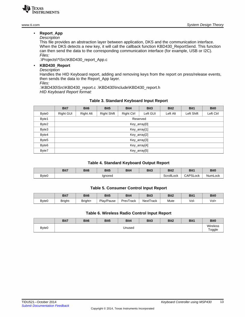
• KBD430_ReportDescriptionHandles the HID Keyboard report, adding and removing keys from the report on press/release events,then sends the data to the Report_App layer.Files:.\KBD430\Src\KBD430_report.c .\KBD430\Include\KBD430_report.hHID Keyboard Report format:
Table 3. Standard Keyboard Input Report
Bit7 Bit6 Bit5 Bit4 Bit3 Bit2 Bit1 Bit0Byte0 Right GUI Right Alt Right Shift Right Ctrl Left GUI Left Alt Left Shift Left CtrlByte1 ReservedByte2 Key_array[0]Byte3 Key_array[1]Byte4 Key_array[2]Byte5 Key_array[3]Byte6 Key_array[4]Byte7 Key_array[5]
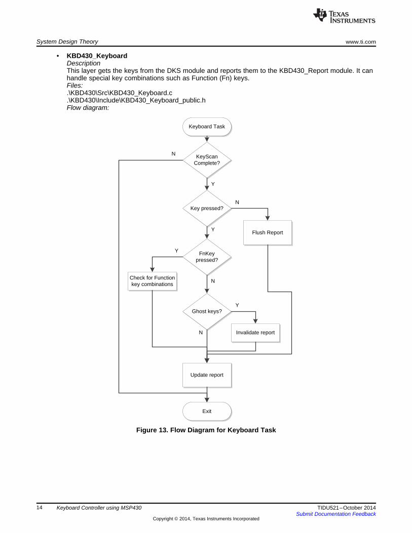
• KBD430_KeyboardDescriptionThis layer gets the keys from the DKS module and reports them to the KBD430_Report module. It canhandle special key combinations such as Function (Fn) keys.Files:.\KBD430\Src\KBD430_Keyboard.c.\KBD430\Include\KBD430_Keyboard_public.hFlow diagram:
• KBD430_DKS (Digital Keyscan)DescriptionThis layer handles the digital keyboard scanning, detecting key press/release events, and reportingthem to higher layers.Files:.\KBD430\Src\KBD430_DKS.c.\KBD430\Include\KBD430_DKS.hState Diagram:
Figure 14. State Diagram for Keyboard Scan
• KBD430_DelayTimerDescriptionThis module handles a general purpose interrupt timer used to implement a delay.This timer is implemented using TA0.0.Files:.\KBD430\Src\KBD430_delaytimer.c.\KBD430\Include\KBD430_delaytimer.h
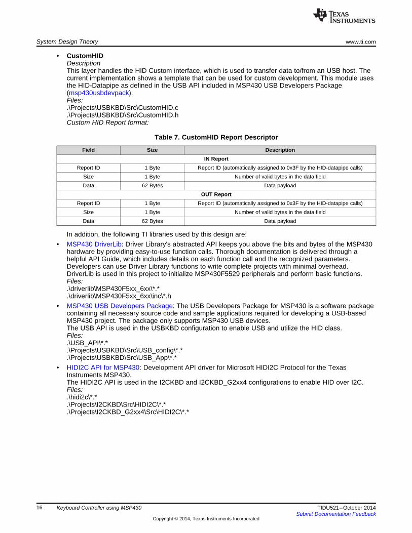
• CustomHIDDescriptionThis layer handles the HID Custom interface, which is used to transfer data to/from an USB host. Thecurrent implementation shows a template that can be used for custom development. This module usesthe HID-Datapipe as defined in the USB API included in MSP430 USB Developers Package(msp430usbdevpack).Files:.\Projects\USBKBD\Src\CustomHID.c.\Projects\USBKBD\Src\CustomHID.hCustom HID Report format:
Table 7. CustomHID Report Descriptor
Field Size DescriptionIN Report
Report ID 1 Byte Report ID (automatically assigned to 0x3F by the HID-datapipe calls)Size 1 Byte Number of valid bytes in the data fieldData 62 Bytes Data payload
OUT ReportReport ID 1 Byte Report ID (automatically assigned to 0x3F by the HID-datapipe calls)
Size 1 Byte Number of valid bytes in the data fieldData 62 Bytes Data payload
In addition, the following TI libraries used by this design are:• MSP430 DriverLib: Driver Library's abstracted API keeps you above the bits and bytes of the MSP430
hardware by providing easy-to-use function calls. Thorough documentation is delivered through ahelpful API Guide, which includes details on each function call and the recognized parameters.Developers can use Driver Library functions to write complete projects with minimal overhead.DriverLib is used in this project to initialize MSP430F5529 peripherals and perform basic functions.Files:.\driverlib\MSP430F5xx_6xx\*.*.\driverlib\MSP430F5xx_6xx\inc\*.h
• MSP430 USB Developers Package: The USB Developers Package for MSP430 is a software packagecontaining all necessary source code and sample applications required for developing a USB-basedMSP430 project. The package only supports MSP430 USB devices.The USB API is used in the USBKBD configuration to enable USB and utilize the HID class.Files:.\USB_API\*.*.\Projects\USBKBD\Src\USB_config\*.*.\Projects\USBKBD\Src\USB_App\*.*
• HIDI2C API for MSP430: Development API driver for Microsoft HIDI2C Protocol for the TexasInstruments MSP430.The HIDI2C API is used in the I2CKBD and I2CKBD_G2xx4 configurations to enable HID over I2C.Files:.\hidi2c\*.*.\Projects\I2CKBD\Src\HIDI2C\*.*.\Projects\I2CKBD_G2xx4\Src\HIDI2C\*.*
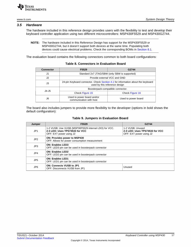
3.5 HardwareThe hardware included in this reference design provides users with the flexibility to test and develop theirkeyboard controller application using two different microcontrollers: MSP430F5529 and MSP430G2744.
NOTE: The hardware included in this Reference Design has support for the MSP430F5529 orMSP430G2744, but it doesn’t support both devices at the same time. Populating bothdevices could cause electrical problems. Check the corresponding BOMs in Section 8.1.
The evaluation board contains the following connectors common to both board configurations:
Table 8. Connectors in Evaluation Board
Connector F5529 G2744J1 Standard 2x7 JTAG/SBW (only SBW is supported)J2 Provide external VCC and GND
J3 24-pin Keyboard connector. Check Section 4.1 for information about the keyboardused by this reference design
J4-J5Boosterpack-compatible connector.
Check Figure 15 Check Figure 16
J6 Used to power board and/orcommunication with host Used to power board
The board also includes jumpers to provide more flexibility to the developer (options in bold shows thedefault configuration):
Table 9. Jumpers in Evaluation Board
Jumper F5529 G2744
JP11-2 VUSB: Use VUSB (MSP30F5529 internal LDO) for VCC.2-3 LDO: Uses TPS73533 for VCCOFF: EXT power using J2
1-2 VUSB: Unused2-3 LDO: Uses TPS73533 for VCCOFF: EXT power using J2
JP2 ON: Provides power to MSP430OFF: Allows for power consumption measurement
JP3 ON: Enables LED3OFF: LED3 pin can be used in boosterpack connector
JP4 ON: Enables LED2OFF: LED2 pin can be used in boosterpack connector
JP5 ON: Enables LED1OFF: LED1 pin can be used in boosterpack connector
JP6 ON: Connects VUSB to JP1OFF: Disconnects VUSB from JP1 Unused
3.5.1 Using MPS430F5529Using KBD430_BOM_F5529 from Table 19, which utilizes the MSP430F5529 microcontroller, provides alot of flexibility to developers thanks to the microcontroller’s rich set of peripherals, large memory size, andamount of available I/Os. The software included in this reference design supports the following interfaces:
Table 10. Communication Interfaces Supported forMSP430F5529
Target Configuration Communication InterfaceUSBKBD USBI2CKBD I2C
In addition, the evaluation board provides access to:• Additional communication peripherals (for example, UART and SPI): allowing developers to send the
keyboard information to the host using other methods, or simply to implement other communicationinterfaces
• Analog peripherals (ADC and analog comparator): providing flexibility to implement functions such as,reading sensors and transducers, using the same keyboard controller
Additional pins are available in J4-J5 connectors which are Boosterpack-compatible:
Figure 15. Pinout for Boosterpack Connector using MSP430F5529
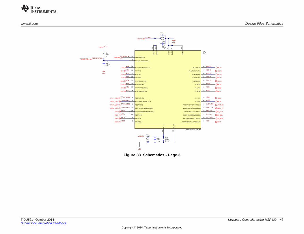
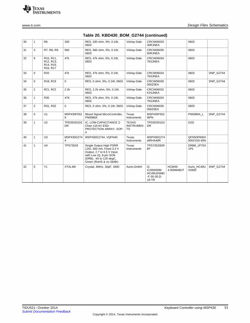
3.5.2 Using MSP430G2744KBD430_BOM_G2744 from Table 20, which utilizes the MSP430G2744 microcontroller, shows a smaller,lower-cost implementation using a value-line device, but it still provides enough flexibility to implementcustom functionality in the application.
The software included in this reference design supports the following interfaces:
Table 12. Communication Interfaces Supported for MSP430G2744
Target Configuration Communication InterfaceI2CKBD_G2xx4 I2C
In addition, the evaluation board allows developers to:• Implement a different communication interface (for example, UART or SPI) to send the keyboard
information to the host using other methods, or simply to implement other communication interfaces• The functionality of LEDs can be disabled allowing developers access to ADC pins to implement
functions such as, reading sensors and transducers, using the same keyboard controller; or to Timerinput/output pins allowing implementation of PWMs, pulse detection, custom communication interfaces,etc
• 3 GPIOs available by default, and up to 9 available if not using I2C and LEDs.
The application reserves the following peripherals and pins for keyboard functionality:
Table 13. Peripherals and Pinout Used for MSP430G2744
Pin/Peripheral Description USBKBDDelayTimer Low power timer delay TA0.0
I2C Communication with host SDA:P3.1/UCB0SDASCL:P3.2/UCB0SCL
P1.0KSI1 P1.1KSI2 P1.2KSI3 P1.3KSI4 P1.4KSI5 P1.5KSI6 P1.6KSI7 P1.7LED1 NumLock LED P2.1LED2 CapsLock LED P2.2LED3 ScrollLock LED P2.3
Additional pins are available in J4-J5 connectors which are Boosterpack-compatible. Note that many pinsare not available because they are reserved for keyboard functions and due to the smaller package of thisdevice.
Figure 16. Pinout for Boosterpack Connector using MSP430G2744
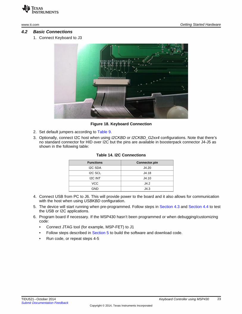
2. Set default jumpers according to Table 9.3. Optionally, connect I2C host when using I2CKBD or I2CKBD_G2xx4 configurations. Note that there’s
no standard connector for HID over I2C but the pins are available in boosterpack connector J4-J5 asshown in the following table:
Table 14. I2C Connections
Functions Connector.pinI2C SDA J4.20I2C SCL J4.18I2C INT J4.10
VCC J4.2GND J4.3
4. Connect USB from PC to J6. This will provide power to the board and it also allows for communicationwith the host when using USBKBD configuration.
5. The device will start running when pre-programmed. Follow steps in Section 4.3 and Section 4.4 to testthe USB or I2C applications.
6. Program board if necessary. If the MSP430 hasn’t been programmed or when debugging/customizingcode:• Connect JTAG tool (for example, MSP-FET) to J1• Follow steps described in Section 5 to build the software and download code.• Run code, or repeat steps 4-5
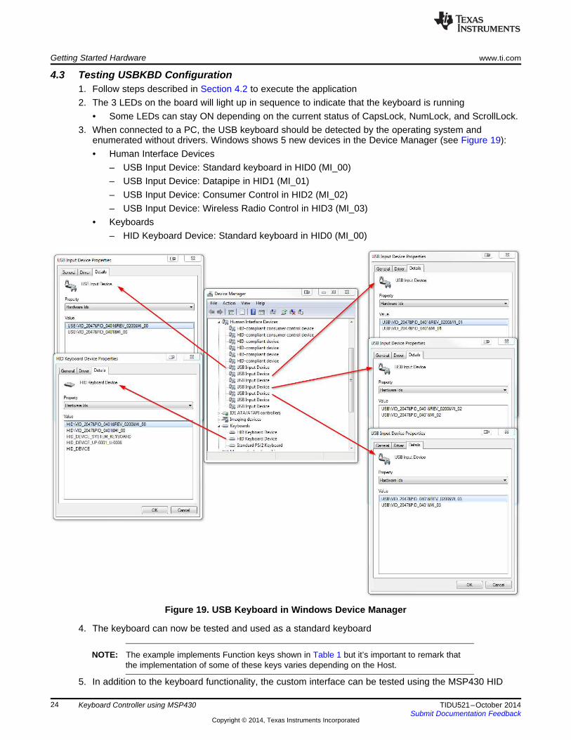
4.3 Testing USBKBD Configuration1. Follow steps described in Section 4.2 to execute the application2. The 3 LEDs on the board will light up in sequence to indicate that the keyboard is running
• Some LEDs can stay ON depending on the current status of CapsLock, NumLock, and ScrollLock.3. When connected to a PC, the USB keyboard should be detected by the operating system and
enumerated without drivers. Windows shows 5 new devices in the Device Manager (see Figure 19):• Human Interface Devices
– USB Input Device: Standard keyboard in HID0 (MI_00)– USB Input Device: Datapipe in HID1 (MI_01)– USB Input Device: Consumer Control in HID2 (MI_02)– USB Input Device: Wireless Radio Control in HID3 (MI_03)
• Keyboards– HID Keyboard Device: Standard keyboard in HID0 (MI_00)
Figure 19. USB Keyboard in Windows Device Manager
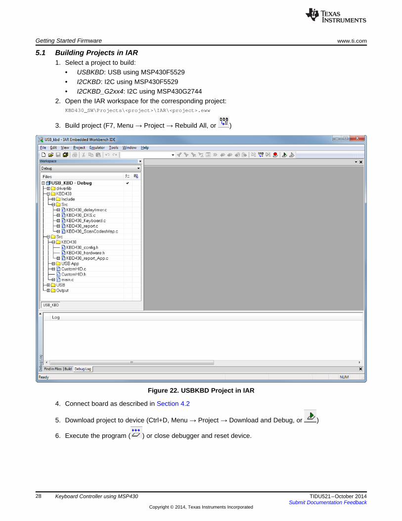
4. The keyboard can now be tested and used as a standard keyboard
NOTE: The example implements Function keys shown in Table 1 but it’s important to remark thatthe implementation of some of these keys varies depending on the Host.
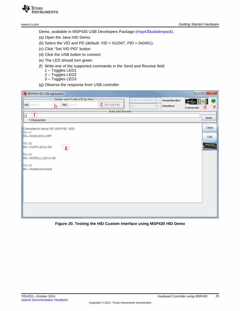
5. In addition to the keyboard functionality, the custom interface can be tested using the MSP430 HID
Demo, available in MSP430 USB Developers Package (msp430usbdevpack).(a) Open the Java HID Demo.(b) Select the VID and PD (default: VID = 0x2047, PID = 0x0401).(c) Click “Set VID PID” button(d) Click the USB button to connect(e) The LED should turn green(f) Write one of the supported commands in the Send and Receive field
1 – Toggles LED12 – Toggles LED23 – Toggles LED3
(g) Observe the response from USB controller
Figure 20. Testing the HID Custom Interface using MSP430 HID Demo
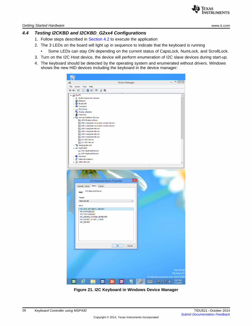
4.4 Testing I2CKBD and I2CKBD_G2xx4 Configurations1. Follow steps described in Section 4.2 to execute the application2. The 3 LEDs on the board will light up in sequence to indicate that the keyboard is running
• Some LEDs can stay ON depending on the current status of CapsLock, NumLock, and ScrollLock.3. Turn on the I2C Host device, the device will perform enumeration of I2C slave devices during start-up.4. The keyboard should be detected by the operating system and enumerated without drivers. Windows
shows the new HID devices including the keyboard in the device manager:
5. The keyboard can now be tested and used as a standard keyboard
NOTE: The example implements Function keys shown in Table 1 but it’s important to remark thatthe implementation of some of these keys varies depending on the Host.
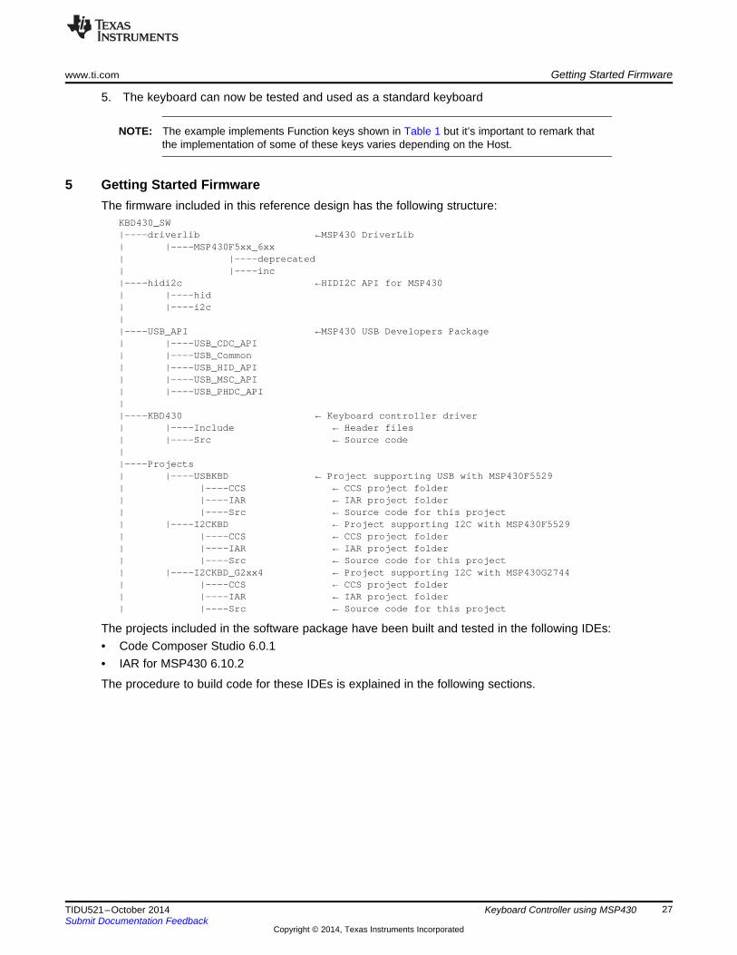
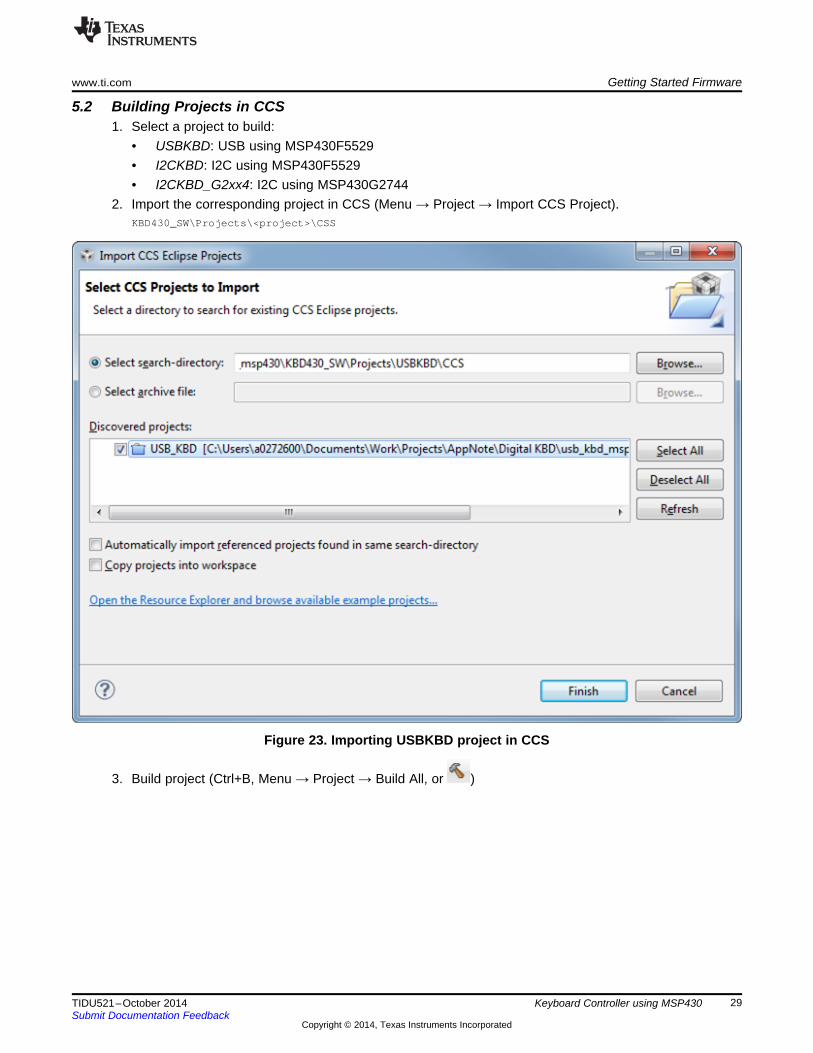
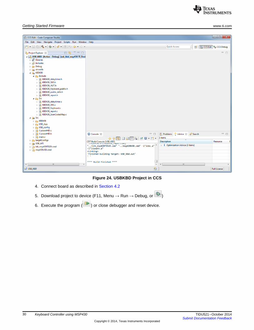
5 Getting Started FirmwareThe firmware included in this reference design has the following structure:
KBD430_SW|----driverlib ←MSP430 DriverLib| |----MSP430F5xx_6xx| |----deprecated| |----inc|----hidi2c ←HIDI2C API for MSP430| |----hid| |----i2c||----USB_API ←MSP430 USB Developers Package| |----USB_CDC_API| |----USB_Common| |----USB_HID_API| |----USB_MSC_API| |----USB_PHDC_API||----KBD430 ← Keyboard controller driver| |----Include ← Header files| |----Src ← Source code||----Projects| |----USBKBD ← Project supporting USB with MSP430F5529| |----CCS ← CCS project folder| |----IAR ← IAR project folder| |----Src ← Source code for this project| |----I2CKBD ← Project supporting I2C with MSP430F5529| |----CCS ← CCS project folder| |----IAR ← IAR project folder| |----Src ← Source code for this project| |----I2CKBD_G2xx4 ← Project supporting I2C with MSP430G2744| |----CCS ← CCS project folder| |----IAR ← IAR project folder| |----Src ← Source code for this project
The projects included in the software package have been built and tested in the following IDEs:• Code Composer Studio 6.0.1• IAR for MSP430 6.10.2
The procedure to build code for these IDEs is explained in the following sections.
6 Customizing the Keyboard ControllerThe software and hardware provided in this reference design provide an easy-to-use out-of-boxexperience for demos and testing, but it also provides a starting point for developers trying to implementtheir own keyboard controller in different applications.
The following sections describe some common customizations, but many more can be implemented bydevelopers.
6.1 USB Interface Customizations
6.1.1 USB VID/PIDDevelopers can modify the VID/PID of the application in order to use their own
Instructions:1. Modify Macros USB_VID and USB_PID in:
6.1.3 USB DescriptorsUSB interfaces can be modified to meet particular needs. This includes removing unwanted interfaces, oradding other interfaces such as CDC or MSC.
Instructions:1. Modify the USB descriptors in the following files:
2. The MSP430 USB Developers Package (msp430usbdevpack) includes a USB Descriptor tool whichcan help creating descriptors for the USB API
3. Add/remove application code as necessary to support descriptors. DefinitionsUSE_CONSUMER_REPORT, USE_WRC_REPORT, and USE_CUSTOM_HID can be used to disableapplication calls to these interfaces. These definitions are in:.\Projects\Projects\USBKBD\Src\KBD430\KBD430_config.h
6.1.4 Polling IntervalThe USB interface defines the interface polling rate in the interface descriptors. This polling rate can bemodified with a direct impact on the response time of the keyboard.
Instructions:1. Modify the bInterval parameter (in ms) in the corresponding interface descriptor found in:
USCIBx ← Constant definitionUSCIBx_ADDR ← Slave address used for this interfaceUSCIBx_GPIO_POUT ← Slave address used for this interfaceUSCIBx_GPIO_PDIR ← PxDIR register used for I2C_INTUSCIBx_GPIO_PIN ← PxIN register used for I2C_INTUSCIBx_PORT ← PxSEL register used to initialize I2C pins functionalityUSCIBx_PINS ← Pins used for I2C (SDA/SCL)
6.2.3 HIDI2C Report DescriptorsThe HID interface can be modified to meet particular needs of the developer. Reports can be modified,removed or added as needed.
Instructions:1. Modify the HID descriptors in the following file:
2. Add/remove application code as necessary to support descriptors. DefinitionsUSE_CONSUMER_REPORT and USE_WRC_REPORT can be used to disable application use ofthese reports. These definitions are in:.\Projects\Projects\<I2CKBDproject>\Src\KBD430\KBD430_config.h
Codes are defined by USB.org HID Usage tables and they are defined in the following file:.\KBD430\Include\KBD430_HUT.h
3. hidUsageReserved must be used for unavailable keys. During keyboard initialization, the driver willcheck for unimplemented keys in order to detect “ghost” keys properly.
4. Additional entries can be added to this table for matrix arrays different from 15x8. Note that this willalso require changes to the key scan driver which are described in Section 6.3.3.
6.3.2 Function KeysThe software included in this reference design has support for function keys defined in Table 1. Theimplementation of function keys can vary, but developers can customize these keys as needed and/or addnew function keys to their implementations.
Instructions:1. Make sure the Fn key is defined as hidUsageReservedFn in the USBKBD_scancodes_s table (check
Section 6.3.1). The function CheckforFnKey() will detect when the Fn key is pressed and it will set aflag in order to handle this special case.
2. If required, modify the report descriptors to add new functions or customize existing ones (checkSection 6.1.3 and Section 6.2.3for USB and I2C respectively). The report descriptors included in thesoftware example include support for some keys defined in the Consumer Control Usage table andone key defined in the Wireless Radio Control usage table. More details of HID report descriptors canbe found in HID Usage tables.
3. Customize the keyboard response for each Function key combination. GetFnKey() includes a switch-case statement with the implementation of all key combinations. This function is located in thefollowing file:.\KBD430\Src\KBD430_Keyboard.c
Note that in some cases, the keyboard combination can simply return a new standard key:case hidUsageF11:
return hidUsageKeypadNumlock; // Fn + F11 = Num Lock
But in order cases, it will have special functionality as follows:case hidUsageF8:
The macros CONSUMER_KEY and WRC_KEY are simply used to differentiate between normal keysand special ones.
4. If implementing a report different from Consumer Control and Wireless Radio Control, add thecorresponding handlers to add and remove keys in UpdateHIDReport() and to send the report inKBD430_Report_Update(). Use the existing implementation, conditionally built usingUSE_CONSUMER_REPORT and USE_WRC_REPORT macros, as a base.
The number of keys resulting from multiplying KSIxKSO must be the same as the number of entries inUSBKBD_scancodes_s table (check Section 6.3.1).
2. Define the KSI port (columns) in the following file:.\Projects\<project>\Src\KBD430\KBD430_hardware.h
Note that this implementation uses a single 8-bit port to implement al columns. This allows for aneasier and faster read of the whole column at the same time and easier handling of the ISR. Thefollowing definitions must be modified:
KSI_IN ← PxIN register for KSIKSI_OUT ← PxOUT register for KSIKSI_DIR ← PxDIR register for KSIKSI_IES ← PxIES register for KSIKSI_IFG ← PxIFG register for KSIKSI_IE ← PxIE register for KSIKSI_ALL ← Bits used for KSIKSI_READ() ← Macro to read KSI portKSI_VECTOR ← KSI interrupt vector
3. Define the KSO pins (rows) in the same file. KSO pins can be located anywhere in the microcontroller.The pins are defined as follows:
KSOx_POUT ← Address of PxOUT register for this KSO pinKSOx_BIT ← Bit used by this KSO pin
Note that the KSO pins are stored in the KSO_Pinmap array.4. Define KSO_Px_ALL for each port used by KSO pins. This definition is optional but it can be used by
macros which write to the whole ports in a faster way.5. Modify KSO_PDIR_OFFSET if needed. The driver uses KSOx_POUT as the base address for each
port. But it uses the KSO_PDIR_OFFSET to access the corresponding PxDIR register. For example, ifthe address of P1OUT is 0x0202 in MSP430F5529, and P1DIR is 0x0204, the value ofKSO_PDIR_OFFSET will be 0x02.
6. Modify keyboard macros SET_KSO_INTERRUPT, SET_KSO_POLL and SET_KSO_IDLE. Thesemacros set the state of the KSO pins in column-interrupt, polling or idle mode. The macros writedirectly to complete KSO ports in order to run faster. When possible, write to the 16-bit register (forexample, PAOUT/PADIR/PAREN) instead of 8-bit registers (for example, P1OUT/P1DIR/P1REN).
7. If the number of KSO pins is different, add/remove entries in KSO_Pinmap, found in:.\KBD430\Src\KBD430_DKS.c
6.3.4 Scan RateThe scan rate of the keyboard can be modified to reduce power consumption, or increase the responsetime.
Instructions:1. Adjust DELAY_SCAN_CYCLES as required in the following file:
6.4.1 MCU System InitializationThe software included in this reference design initializes basic MCU system peripherals as follows:• Watchdog disabled• MCLK=SMCLK = DCO = 8MHz• Unused GPIOs = Output Low• SVSL/SVML/SVMH = disabled, SVSH=full performance → MSP430F5529 only• VCore=2 (USBKBD) or VCore=0 (I2CKBD) → MSP430F5529 only
Developers can modify these settings as required or when using a different hardware or MSP430derivative.
Instructions:1. Modify Init_Clock() to initialize MSP430 clocks. This function is located in:
.\Projects\<project>\Src\main.c
2. In the same file, modify Init_Ports() to initialize MSP430 GPIOs.• KSI pins should be initialized as inputs.• KSO pins as output low.• LED pins as output low.• Unused pins should have an internal/external pull-up/down resistor or be configured as output.
3. Other basic initialization can be performed in main().
6.4.2 Keyboard LEDsThe application uses 3 LEDs for NumLock, CapsLock and ScrollLock. Developers can use different pinsfor these functions or simply remove the functionality.
Instructions:1. The LED pins are defined in:
.\Projects\<project>\Src\KBD430\KBD430_hardware.h
The following definitions are available:
LED_PORT_W ← PxOUT register for LEDsLEDNUM_1_1 ← Pin used for Num LockLEDCAPS_1_6 ← Pin used for Caps LockLEDSCROLL_1_7 ← Pin used for Scroll Lock
2. The LEDs are handled in the application layer after getting a report from the HID interface. Modify theimplementation in main() if needed.
6.4.3 USB Custom InterfaceThe USBKBD configuration includes an HID custom interface which can be used to exchange customdata with the USB host. The implementation shown in this reference design is very simplistic but it can beused as a base for further development.
Instructions:1. Modify CustomHID_Parse() to parse and interpret data from USB Host. This function is declared in:.\Projects\USBKBD\Src\CustomHID.c
The current implementation implements a simple switch-case statement handling the different commandsfrom USB Host.
6.5 Firmware UpdatesSection 5 explains the procedure required to program the device using the JTAG connector. While thisoption is useful during development, it can be inconvenient for field upgrades in many applications.
In addition to the JTAG interface, this reference design allows developers to implement BSLcommunication.
The MSP430 bootstrap loader (BSL) enables users to communicate with embedded memory in theMSP430 microcontroller during the prototyping phase, final production and in service. By using commoninterfaces such as USB, UART or I2C, BSL can be more convenient and easier to implement on the field.
Two BSL methods are implemented depending on the device, and they are explained in more detail in thefollowing sections.
6.5.1 USB BSL in MSP430F5529MSP430F5529 is shipped with a USB BSL which resides in Flash. This BSL can be forced in hardwareusing the PUR pin, however the development board included in this design doesn’t have easy access tothis pin, so a software method is used instead.
The procedure is explained in the following steps:1. The USB BSL method can be used in the following projects:
• USBKBD: USB using MSP430F5529• I2CKBD: I2C using MSP430F5529
2. The default configuration for these projects includes a definition ENABLE_SW_BSL which enablessoftware BSL calls.If this definition is not enabled, the device can’t force BSL mode.
3. Disconnect the device from the USB port4. Press 'm', 's', and 'p' keys at the same time5. With the keys pressed, connect to USB port.
This will force a BOR, the MSP430 will reset and check for the ‘m’,’s’,and ’p’ keys. If the keys arepressed, the device jumps to BSL; if not, the device will execute the application.
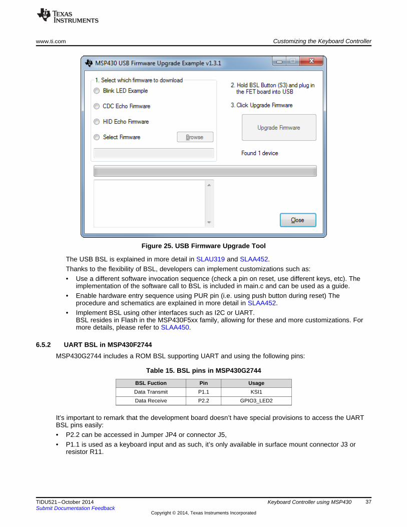
6. The 3 LEDs will blink at the same time to indicate entry to BSL mode7. The 3 keys can be released at this point8. A host application such as “MSP430 USB Firmware Upgrade Example”, available here, can be used to
update the firmware:
NOTE: The new firmware should enable ENABLE_SW_BSL in order to be able to update again.
The USB BSL is explained in more detail in SLAU319 and SLAA452.Thanks to the flexibility of BSL, developers can implement customizations such as:• Use a different software invocation sequence (check a pin on reset, use different keys, etc). The
implementation of the software call to BSL is included in main.c and can be used as a guide.• Enable hardware entry sequence using PUR pin (i.e. using push button during reset) The
procedure and schematics are explained in more detail in SLAA452.• Implement BSL using other interfaces such as I2C or UART.
BSL resides in Flash in the MSP430F5xx family, allowing for these and more customizations. Formore details, please refer to SLAA450.
6.5.2 UART BSL in MSP430F2744MSP430G2744 includes a ROM BSL supporting UART and using the following pins:
It’s important to remark that the development board doesn’t have special provisions to access the UARTBSL pins easily:• P2.2 can be accessed in Jumper JP4 or connector J5,• P1.1 is used as a keyboard input and as such, it’s only available in surface mount connector J3 or
This BSL is usually invoked in hardware using the TEST and RESET using the entry sequence describedin SLAU319; however this reference design includes a software invocation sequence described in thefollowing steps:1. The UART BSL method can be used in the followuing projects
• I2CKBD_G2xx4: I2C using MSP430G27442. The default configuration for these projects includes a definition ENABLE_SW_BSL which enables
software BSL calls. If this definition is not enabled, the device can’t force BSL mode.3. Disconnect the device from the USB port or power off device.4. Press ‘m’, ‘s’, and ‘p’ keys at the same time5. With the keys pressed, connect to USB port or power up the device.
This will force a BOR, the MSP430 will reset and check for the ‘m’,’s’,and ’p’ keys. If the keys arepressed, the device jumps to BSL; if not, the device will execute the application.
6. The 3 LEDs will blink at the same time to indicate entry to BSL mode7. The 3 keys can be released at this point8. A host application such as BSLDEMO -included in SLAU319- and hardware such as MSP430-BSL
Rocket can be used to update the firmware.
NOTE: The new firmware should enable ENABLE_SW_BSL in order to be able to update again.
Figure 26. BSLDEMO Tool
The UART BSL is explained in more detail in SLAU319.
Developers can implement customizations such as:• Use a different software invocation sequence (check a pin on reset, use different keys, etc).
The implementation of the software call to BSL is included in main.c and can be used as a guide.• Make the BSL pins easily available.
As mentioned previously, the development board doesn’t have special provisions to access BSL pins.Developers can make a special connector for BSL pins and reserve these pins for this purpose.Additionally, this connector can include the TEST and RESET pins used to force the hardware entrysequence.
• The ROM BSL is fixed to UART, but developers can implement a bootloader using other interfaces.MSPBoot included in SLAA600 shows the implementation of a bootloader which resides in main flashand supports UART, I2C and SPI.
7 Test Data
7.1 Test SetupThe board should be connected following the guidelines described in Section 4.
To measure power consumption:• Disconnect JP2 and connect an ammeter in series
7.2 Response TimeThe response time for keyboards is approximately 5ms to 50ms. While this depends on different factorssuch as the mechanical implementation of the keyboard, communication bus load, etc., by using thisreference design, developers have more flexibility to customize the application according to their needs.Whether response time, price or power consumption is the most important requirement, parameters suchas debounce time, USB polling interval, and microcontroller internal frequency can be adjusted to meetparticular requirements.
One important factor affecting the response time is the scan time, which defines the time required to scanall keys. While a key press is detected in a few cycles in column-interrupt mode, the algorithm torecognize the particular pressed key, debounce it, discard “ghost” keys, etc. can take more cycles.
The following measurements were observed on bench tests:
Time CyclesDKS Scan ~182us@8MHz ~1450 cyclesDKS Process (1st key) ~339us@8MHz ~2715 cyclesDKS Process (additional keys) ~108us@8MHz ~860 cycles
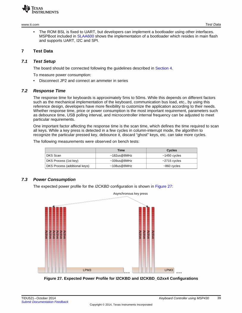
7.3 Power ConsumptionThe expected power profile for the I2CKBD configuration is shown in Figure 27:
Figure 27. Expected Power Profile for I2CKBD and I2CKBD_G2xx4 Configurations
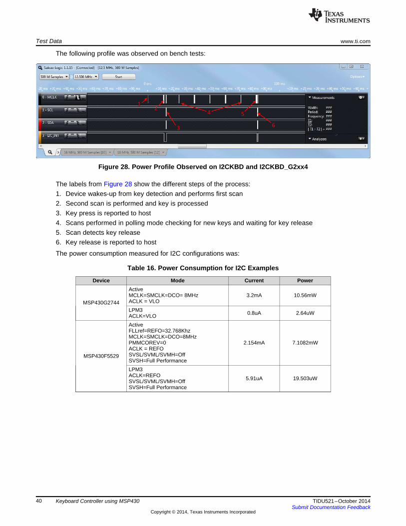
The following profile was observed on bench tests:
Figure 28. Power Profile Observed on I2CKBD and I2CKBD_G2xx4
The labels from Figure 28 show the different steps of the process:1. Device wakes-up from key detection and performs first scan2. Second scan is performed and key is processed3. Key press is reported to host4. Scans performed in polling mode checking for new keys and waiting for key release5. Scan detects key release6. Key release is reported to host
The power consumption measured for I2C configurations was:
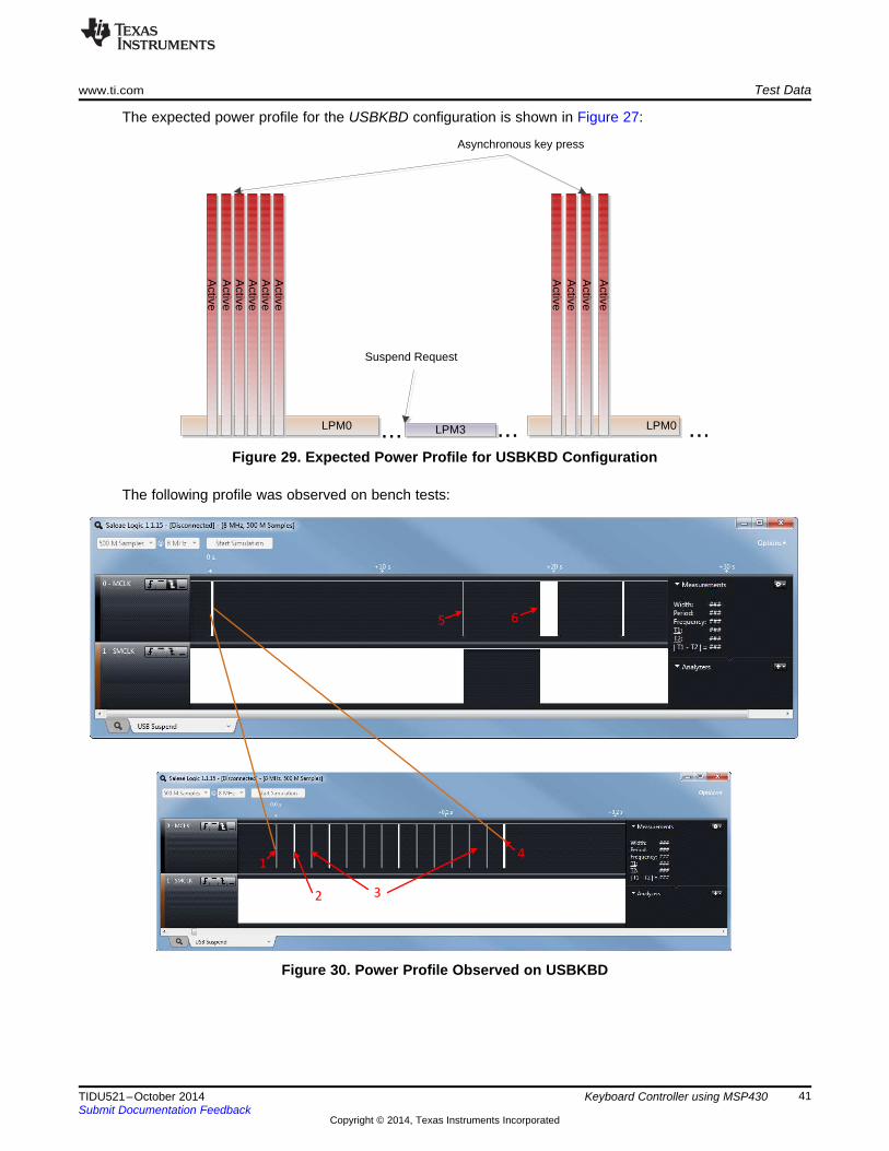
The labels from Figure 30 show the different steps of the process:1. Device wakes-up from key detection and performs first scan2. Second scan is performed, key is processed and sent to host3. Scans performed in polling mode checking for new keys and waiting for key release4. Scan detects key release and key is reported to host5. Device detects a request to go to Suspend mode and goes to LPM36. Keyboard controller detects a key event and requests a USB remote wake-up
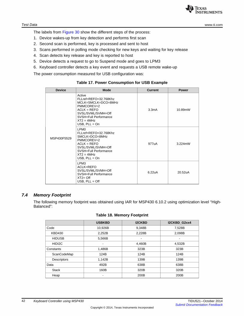
The power consumption measured for USB configuration was:
Table 17. Power Consumption for USB Example
Device Mode Current Power
MSP430F5529
ActiveFLLref=REFO=32.768KhzMCLK=SMCLK=DCO=8MHzPMMCOREV=2ACLK = REFOSVSL/SVML/SVMH=OffSVSH=Full PerformanceXT2 = 4MHzUSB, PLL = On
3.3mA 10.89mW
LPM0FLLref=REFO=32.768KhzSMCLK=DCO=8MHzPMMCOREV=2ACLK = REFOSVSL/SVML/SVMH=OffSVSH=Full PerformanceXT2 = 4MHzUSB, PLL = On
977uA 3.224mW
LPM3ACLK=REFOSVSL/SVML/SVMH=OffSVSH=Full PerformanceXT2= OffUSB, PLL = Off
6.22uA 20.52uA
7.4 Memory FootprintThe following memory footprint was obtained using IAR for MSP430 6.10.2 using optimization level “High-Balanced”:
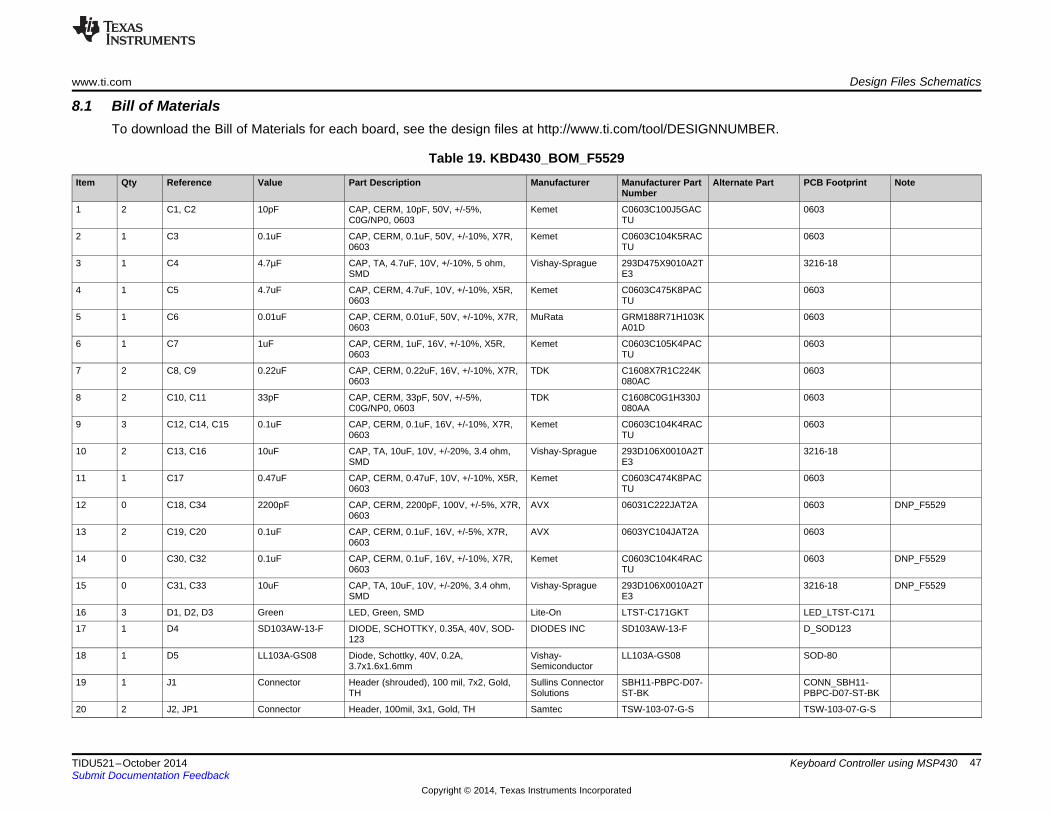
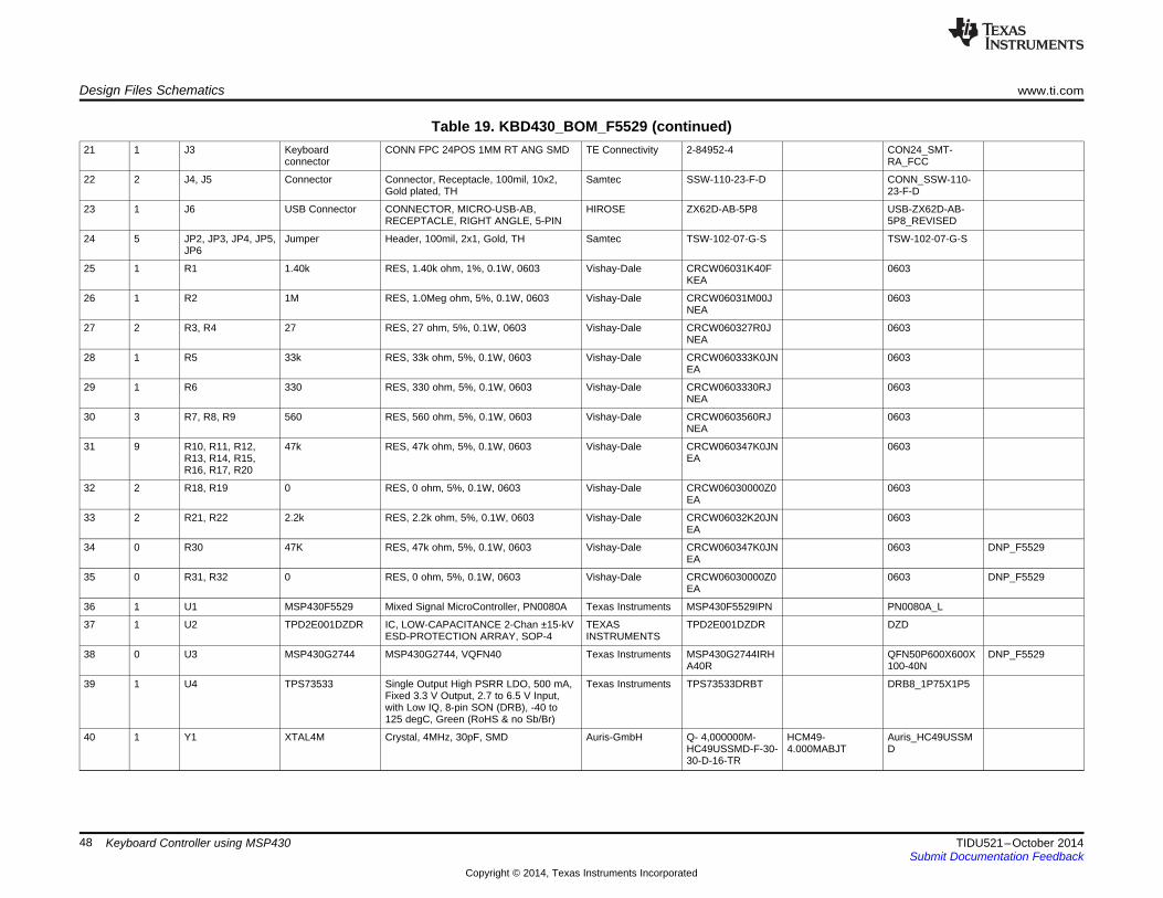
39 1 U4 TPS73533 Single Output High PSRR LDO, 500 mA,Fixed 3.3 V Output, 2.7 to 6.5 V Input,with Low IQ, 8-pin SON (DRB), -40 to125 degC, Green (RoHS & no Sb/Br)
41 1 U4 TPS73533 Single Output High PSRRLDO, 500 mA, Fixed 3.3 VOutput, 2.7 to 6.5 V Input,with Low IQ, 8-pin SON(DRB), -40 to 125 degC,Green (RoHS & no Sb/Br)
8.3 Altium ProjectTo download the Altium project files for each board, see the design files athttp://www.ti.com/tool/DESIGNNUMBER.
8.4 Gerber FIlesTo download the Gerber files for each board, see the design files athttp://www.ti.com/tool/DESIGNNUMBER.
9 Software FilesTo download the software files for this reference design, please see the link athttp://www.ti.com/tool/DESIGNNUMBER.
10 References1. 1. MSP430x5xx and MSP430x6xx Family User’s Guide (SLAU208)2. 2. MSP430x2xx Family User’s Guide (SLAU144)3. 3. Implementing an Ultralow-Power Keypad Interface with the MSP430, 2002 (SLAA149)4. 4. Enabling Low-Power Windows 8 HID Over I2C Applications using MSP430 Microcontrollers, 2012
(SLAA569)5. Programming With the Bootstrap Loader (BSL), 2014 (SLAU319)6. Creating a Custom Flash-Based Bootstrap Loader (BSL), 2013 (SLAA450)7. USB Field Firmware Update on MSP430™ MCUs, 2011 (SLAA452)8. MSPBoot - Main Memory Bootloader for MSP430™ Microcontrollers, 2014 (SLAA600)9. 5. USB HID Usage Tables. http://www.usb.org/developers/hidpage/
11 About the AuthorLuis Reynoso is an Applications Engineer at Texas Instruments. He has taken multiple customer-facingroles in the embedded industry, and during this time he has published several Applications Notes andpapers for microcontrollers. He joined the MSP430 Applications team in 2010.
Texas Instruments Incorporated (‘TI”) reference designs are solely intended to assist designers (“Designer(s)”) who are developing systemsthat incorporate TI products. TI has not conducted any testing other than that specifically described in the published documentation for aparticular reference design.TI’s provision of reference designs and any other technical, applications or design advice, quality characterization, reliability data or otherinformation or services does not expand or otherwise alter TI’s applicable published warranties or warranty disclaimers for TI products, andno additional obligations or liabilities arise from TI providing such reference designs or other items.TI reserves the right to make corrections, enhancements, improvements and other changes to its reference designs and other items.Designer understands and agrees that Designer remains responsible for using its independent analysis, evaluation and judgment indesigning Designer’s systems and products, and has full and exclusive responsibility to assure the safety of its products and compliance ofits products (and of all TI products used in or for such Designer’s products) with all applicable regulations, laws and other applicablerequirements. Designer represents that, with respect to its applications, it has all the necessary expertise to create and implementsafeguards that (1) anticipate dangerous consequences of failures, (2) monitor failures and their consequences, and (3) lessen thelikelihood of failures that might cause harm and take appropriate actions. Designer agrees that prior to using or distributing any systemsthat include TI products, Designer will thoroughly test such systems and the functionality of such TI products as used in such systems.Designer may not use any TI products in life-critical medical equipment unless authorized officers of the parties have executed a specialcontract specifically governing such use. Life-critical medical equipment is medical equipment where failure of such equipment would causeserious bodily injury or death (e.g., life support, pacemakers, defibrillators, heart pumps, neurostimulators, and implantables). Suchequipment includes, without limitation, all medical devices identified by the U.S. Food and Drug Administration as Class III devices andequivalent classifications outside the U.S.Designers are authorized to use, copy and modify any individual TI reference design only in connection with the development of endproducts that include the TI product(s) identified in that reference design. HOWEVER, NO OTHER LICENSE, EXPRESS OR IMPLIED, BYESTOPPEL OR OTHERWISE TO ANY OTHER TI INTELLECTUAL PROPERTY RIGHT, AND NO LICENSE TO ANY TECHNOLOGY ORINTELLECTUAL PROPERTY RIGHT OF TI OR ANY THIRD PARTY IS GRANTED HEREIN, including but not limited to any patent right,copyright, mask work right, or other intellectual property right relating to any combination, machine, or process in which TI products orservices are used. Information published by TI regarding third-party products or services does not constitute a license to use such productsor services, or a warranty or endorsement thereof. Use of the reference design or other items described above may require a license from athird party under the patents or other intellectual property of the third party, or a license from TI under the patents or other intellectualproperty of TI.TI REFERENCE DESIGNS AND OTHER ITEMS DESCRIBED ABOVE ARE PROVIDED “AS IS” AND WITH ALL FAULTS. TI DISCLAIMSALL OTHER WARRANTIES OR REPRESENTATIONS, EXPRESS OR IMPLIED, REGARDING THE REFERENCE DESIGNS OR USE OFTHE REFERENCE DESIGNS, INCLUDING BUT NOT LIMITED TO ACCURACY OR COMPLETENESS, TITLE, ANY EPIDEMIC FAILUREWARRANTY AND ANY IMPLIED WARRANTIES OF MERCHANTABILITY, FITNESS FOR A PARTICULAR PURPOSE, AND NON-INFRINGEMENT OF ANY THIRD PARTY INTELLECTUAL PROPERTY RIGHTS.TI SHALL NOT BE LIABLE FOR AND SHALL NOT DEFEND OR INDEMNIFY DESIGNERS AGAINST ANY CLAIM, INCLUDING BUT NOTLIMITED TO ANY INFRINGEMENT CLAIM THAT RELATES TO OR IS BASED ON ANY COMBINATION OF PRODUCTS ASDESCRIBED IN A TI REFERENCE DESIGN OR OTHERWISE. IN NO EVENT SHALL TI BE LIABLE FOR ANY ACTUAL, DIRECT,SPECIAL, COLLATERAL, INDIRECT, PUNITIVE, INCIDENTAL, CONSEQUENTIAL OR EXEMPLARY DAMAGES IN CONNECTION WITHOR ARISING OUT OF THE REFERENCE DESIGNS OR USE OF THE REFERENCE DESIGNS, AND REGARDLESS OF WHETHER TIHAS BEEN ADVISED OF THE POSSIBILITY OF SUCH DAMAGES.TI’s standard terms of sale for semiconductor products (http://www.ti.com/sc/docs/stdterms.htm) apply to the sale of packaged integratedcircuit products. Additional terms may apply to the use or sale of other types of TI products and services.Designer will fully indemnify TI and its representatives against any damages, costs, losses, and/or liabilities arising out of Designer’s non-compliance with the terms and provisions of this Notice.IMPORTANT NOTICE