Keyboard tap to configure an Amiga 500 jmA500 ¡[email protected]¿ August 13, 2014 1 Description This little piece of hardware is used to provide some means for configuring an Amiga 500 with the keyboard. This is to replace at least some of the small switches that are commonly used to configure the extensions in an Amiga. The circuit listens to the keys pressed on the Amiga keyboard and then adjusts some of its output pins. These pins connect to jumper headers on the extension boards and hence provide some means to configure these extensions without opening the case or drilling holes into it. ISP GND 5V RXD TXD Keyboard Pin 1 Pin 1 Pin 1 Top: JP5 Bottom: JP6 Note however, that this project is not for beginners. If you have other extensions than I have, you will likely have to adapt the firmware to your needs. Also, you have to figure out whether your extensions are configurable by means of an external MCU, that is if 1
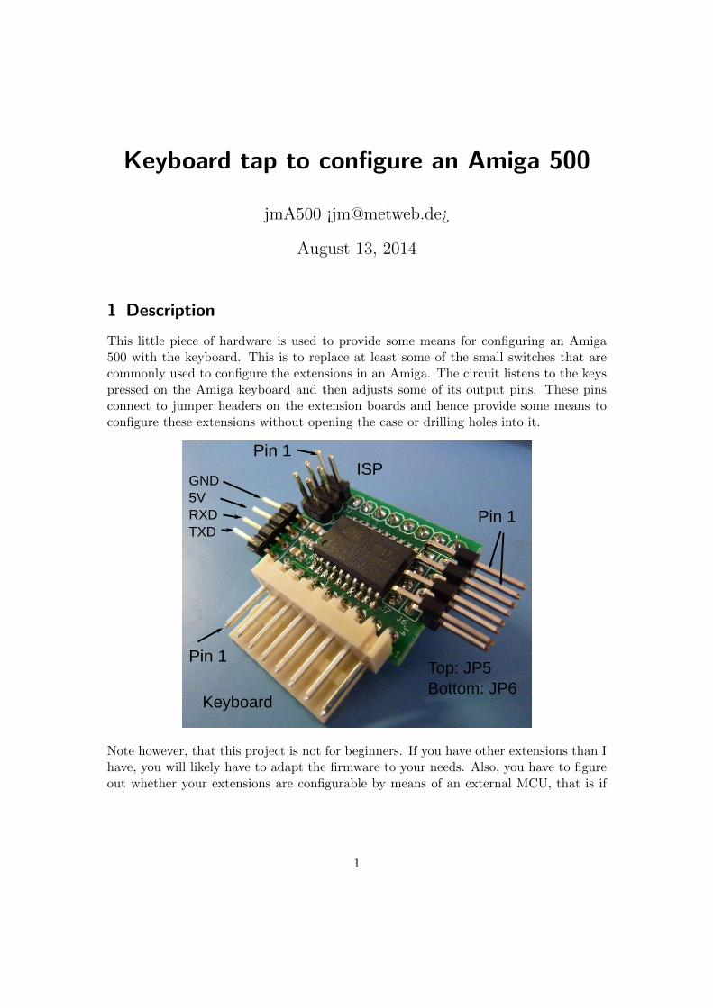
This little piece of hardware is used to provide some means for configuring an Amiga500 with the keyboard. This is to replace at least some of the small switches that arecommonly used to configure the extensions in an Amiga. The circuit listens to the keyspressed on the Amiga keyboard and then adjusts some of its output pins. These pinsconnect to jumper headers on the extension boards and hence provide some means toconfigure these extensions without opening the case or drilling holes into it.
ISPGND5VRXDTXD
Keyboard
Pin 1
Pin 1
Pin 1
Top: JP5Bottom: JP6
Note however, that this project is not for beginners. If you have other extensions than Ihave, you will likely have to adapt the firmware to your needs. Also, you have to figureout whether your extensions are configurable by means of an external MCU, that is if
1
is suffices to drive a signal statically high or low. Switching a dynamic signal is notpossible (without extra hardware)1
In any case you need a possibility to program the AtTiny2313 micro-controller withan in system programmer (ISP). These are cheaply available and connect to USB orparallel port. A lot of information regarding this micro-controller can be obtained onthe excellent websites http://www.avrfreaks.net/ or http://www.mikrocontroller.net/ (German).
In addition, if you are not running a Linux machine similar to mine there might besome extra difficulties adapting the code to your build environment. In particular Iam not using AVR studio and this distribution does not include any project file for it.However, pre-built firmware images are included, if you are happy with the firmware outof the box.
2 Disclaimer
I am not responsible for any damages done by this device, and I do not guarantee thatit will work at all. Only connect this to your precious Amiga, if you are sure about whatit does, how it works, and whether the firmware is what I claim it to be.
3 Acknowledgments
The idea to this project was born during a discussion in the a1k.org/forum and wassuggested by Paradroid. However, if I did not have all the great hardware extensionscreated by the community I would not have had any reason to start the project. Thanksalso to the members of the a1k.org forum encouraging me to continue this project.
4 License
All parts of this project are free to use in non-commercial projects. The firmware islicensed under terms of the GPL 2. Please quote this document in any derived work.See the file COPYRIGHT in src/attiny4313 for additional information, in particularthe reference to Peter Fleury who provided a neat UART library for the Atmel MCUs.
5 Hardware
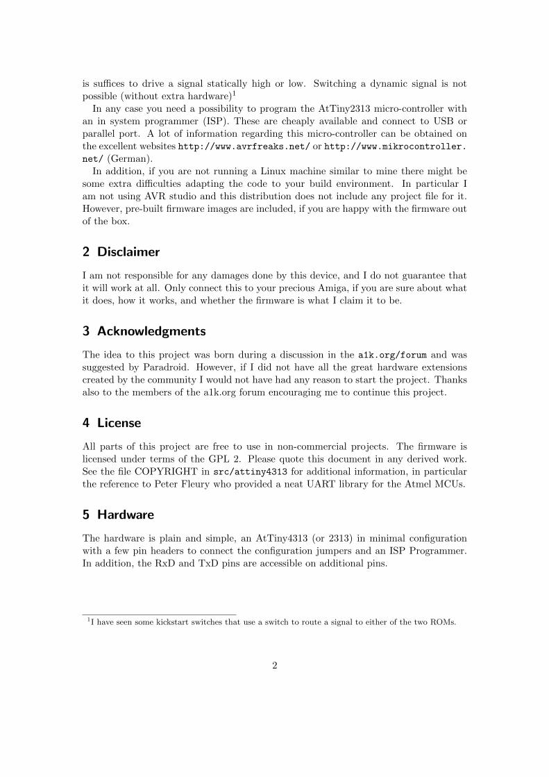
The hardware is plain and simple, an AtTiny4313 (or 2313) in minimal configurationwith a few pin headers to connect the configuration jumpers and an ISP Programmer.In addition, the RxD and TxD pins are accessible on additional pins.
1I have seen some kickstart switches that use a switch to route a signal to either of the two ROMs.
There is a board layout done in such a way that the little PCB can be directly fitted onthe keyboard connector on the mainboard of an Amiga 500(+).
However, the whole circuit is so simple that you might consider building it without aPCB, or you might use an Ardiuno or something similar.
5.1 Part list
IC1 AtTiny 2313 SO or AtTiny 4313 SO
C1,C2 100n SMD 0805
C3 10µ SMD 1206
R1 10k SMD 0805
J1 1x8 socket strip 180◦ 2.54
J2 2x3 pinheader 180◦ 2.54
J3 1x4 pinheader 180◦ 2.54
J4 1x8 pinheader 90◦ 2.54
J5,J6 2x4 pinheader 90◦ 2.54
For future extensions I suggest using a 4313 with 4k flash and 256 bytes of RAM if youcan get one. The current firmware barely fits the 2313 as it uses about 1984 bytes ofits 2k flash memory. On the other hand, approximately half of this is for the UARTinput/output functions that you may or may not find useful. Note that I did not testthe board with a 2313A although that might work without changing the code.
3
5.2 Pin Configuration
5.2.1 J1: Connects to A500 mainboard
1 KBCLK
2 KBDATA
3 KBRESET
4 VCC
5
6 GND
7 POWER LED
8 FLOPPY LED
5.2.2 J2: ISP
This is to connect an ISP programmer. The pin-out corresponds to Atmel 6-pin ISPconnector. Please make sure that the programmer does not power the MCUwhen connected to the A500 mainboard.
1 MISO
2 VCC
3 SCK
4 MOSI
5 RESET
6 GND
5.2.3 J3: Serial connector
This is a serial connection with 5V logic levels. Names are from the perspective of theMCU, so you have to connect the TxD of your computer to the RxD on the PCB.
1 GND
2 VCC
3 RxD
4 TxD
The firmware will output some status messages here, and listens to commands via asmall parser. Have a look at the software how to use it (or send the string help to seea small help message).
5.2.4 J4: Connect your keyboard here
Same as J1.
4
5.3 J5, J6: Connectors for configuration jumpers
These connectors provide 8 pins to configure the hardware. Everything that happenson these pins depends on the firmware. The software provided with this documentationemulates open collector outputs, ie. it will either pull pins low or let them float (configureas inputs) but never pull them high.
My Amiga 500 is equipped with a configurable 1.8/2MB Ranger memory extension[3], a Kickflash [2, 1] and the 68010@14MHz Turbo card by Matze [4]. The configuratoris used to configure all three extensions. The memory extension is connected to J5,Kickflash and Turbo card to J6 as follows:
J5 1 EXRAM
2 CHIPRAM
3 CONF0
4 CONF1
J6 1 Kickflash (DIP Switch 3)
2 Kickflash (DIP Switch 4)
3 Turbo Card
4
Note 1: If you do not own one of the memory expansion boards that I am talking about,you can connect JP5-1 to the on/off switch of a 512k memory expansion cardand use F1/F2/F3 to turn it on and F4/F5 to turn it off.
Note 2: The Kickflash has a MCU on it which must be disabled by removing it or cuttingits power.
Note 3: My version of Matze’s Turbo card needs one extra pull-up resistor on the con-figuration pin to be configurable with the emulated open collector outputs.
6 Firmware
The firmware for the Atmel is written in C and compiles with avr-gcc 4.8.2 but may ormay not compile with different versions although I tried to be as compatible as possible.The directory firmware contains precompiled flash and eeprom images in Hex-formatfor the AtTiny 2313 and 4313. For both MCUs the fuses setting is
LFUSE = 0xD4, HFUSE = 0xDB, EFUSE = 0xFF.
Make sure to program both the flash memory with the corresponding .hex file and theeeprom memory with the .eep file. Never attempt to flash the MCU while pluggedinto a running Amiga 500, since it will switch configuration when finished programming.This could damage your Amiga.
The Makefile provided in the src directory should do the job by simply running make.If compiling for an AtTiny2313 you must adjust the MCU variable in the Makefile to
5
read MCU = attiny2313. If you happen to have a USBasp ISP programmer [5] youcan program the MCU by simply running make fuses and make program. The Make-file supports programming with avrdude, the programmer is selected with the variableAVRDUDE_PROG.
The source code should be mostly self explanatory2, although small code has beenpreferred to readable code in some places. The crucial global variable is conf_data
an array of bytes. This contains the mapping of F-keys to actual configuration. SinceI use the software to configure three extensions, also the bytes in this array are splitinto three parts. The lower four bits correspond to the configurations of the memoryextension using 4 jumpers. The first entry in conf_data is selected via F1, the secondby F2, and so on, up to F10. The index of the current configuration is stored in theglobal variable conf.current[0], the next selection in conf.next[0]. The lower fourbits of conf_data the are then used to set the pins of J5. A one in these bits resultsin pulling the corresponding pin low.
The second extension to configure is the Kickflash. It uses two jumpers and is con-nected to J6-1 and J6-2. The index of the next configuration is in conf.next[1] andselectable by Shift-F1 to Shift-F4. The settings for these jumpers are stored in bits 4 and5 of conf_data[conf.next[0]]. See the function set_config() in main.c for details.
Bit 6 of the conf_data entries is used to enable or disable the turbo card. This bitcorresponds to Shift-F6 and Shift-F7. Selecting the configuration with Shift-F6 resultsin setting conf.next[2] to 0. Since bit 6 in conf_data[0] is set, J6-3 will be pulled lowon the next reset and hence the turbo card is disabled. Selecting the next configurationwith Shift-F7 results in conf.next[2] being 1, and since bit 6 in conf_data[1] is notset, J6-3 will be left floating on the next reset and hence the turbo card is enabled.
7 Usage
This is the selections available if the configurator is connected as described in section 5.3and with the default firmware. The keys F1-F10 are used to configure the memoryexpansion:
F1 Select + 512kB Chipram and + 1.5MB Slow RAM
F2 Select + 512kB Chipram and + 1 MB Slow RAM
F3 Select + 512kB Chipram and + 0.5MB Slow RAM
F4 Select + 512kB Chipram and + 0 MB Slow RAM
F5 Select + 0kB Chipram and + 0 MB Slow RAM
F6 Select + 0kB Chipram and + 1.8 MB Slow RAM
F7 Select + 0kB Chipram and + 1.5 MB Slow RAM
F8 Select + 0kB Chipram and + 1.0 MB Slow RAM
F9 Select + 0kB Chipram and + 0.5 MB Slow RAM
F10 Select + 0kB Chipram and + 0 MB Slow RAM
2An obviously biased judgment YMMV.
6
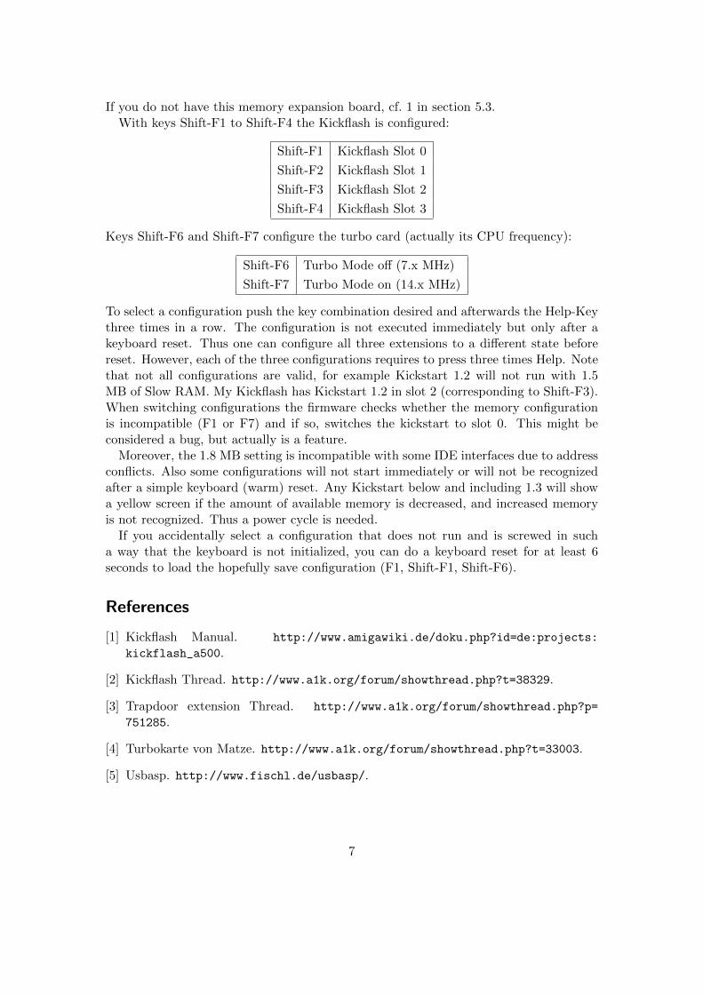
If you do not have this memory expansion board, cf. 1 in section 5.3.With keys Shift-F1 to Shift-F4 the Kickflash is configured:
Shift-F1 Kickflash Slot 0
Shift-F2 Kickflash Slot 1
Shift-F3 Kickflash Slot 2
Shift-F4 Kickflash Slot 3
Keys Shift-F6 and Shift-F7 configure the turbo card (actually its CPU frequency):
Shift-F6 Turbo Mode off (7.x MHz)
Shift-F7 Turbo Mode on (14.x MHz)
To select a configuration push the key combination desired and afterwards the Help-Keythree times in a row. The configuration is not executed immediately but only after akeyboard reset. Thus one can configure all three extensions to a different state beforereset. However, each of the three configurations requires to press three times Help. Notethat not all configurations are valid, for example Kickstart 1.2 will not run with 1.5MB of Slow RAM. My Kickflash has Kickstart 1.2 in slot 2 (corresponding to Shift-F3).When switching configurations the firmware checks whether the memory configurationis incompatible (F1 or F7) and if so, switches the kickstart to slot 0. This might beconsidered a bug, but actually is a feature.
Moreover, the 1.8 MB setting is incompatible with some IDE interfaces due to addressconflicts. Also some configurations will not start immediately or will not be recognizedafter a simple keyboard (warm) reset. Any Kickstart below and including 1.3 will showa yellow screen if the amount of available memory is decreased, and increased memoryis not recognized. Thus a power cycle is needed.
If you accidentally select a configuration that does not run and is screwed in sucha way that the keyboard is not initialized, you can do a keyboard reset for at least 6seconds to load the hopefully save configuration (F1, Shift-F1, Shift-F6).