13
Keysight Technologies Active Differential Probes U1818A 100 kHz to 7 GHz U1818B 100 kHz to 12 GHz Technical Overview

Keysight Technologies Active Differential ProbesU1818A 100 kHz to 7 GHzU1818B 100 kHz to 12 GHz
Technical Overview

Introduction
The Keysight Technologies, Inc. U1818A/B active differential probes provide high differential input impedance from 100 kHz to 7 or 12 GHz. Suitable for those in R&D and quality assurance who are performing RF/Microwave and high-speed digital design and validation work in wireline, wireless communications and aerospace and defense industries. Designed to be directly compatible with Keysight’s network, spectrum and signal source analyzers, these probes enable you to quickly find and fix defects while taking full advantage of the instruments capability.
The U1818A/B active differential probes are available with a variety of probe heads for different application needs. They can also be used with most of Keysight’s probe accessories including extreme temperature extension cable, in-line attenuator kit, minimum loss attenuator pad, DC blocking capacitors, probe positioners and others to achieve accurate measurements.
Key Features and Benefits:
– Broad bandwidth with flat fre-quency, +/- 1.5 dB, which ensures excellent measurement accuracy and helps users achieve the best product specifications.
– Low noise floor, less than -130 dBm/Hz at 10 MHz to 12 GHz, which allows measure-ments to be made at a low signal amplitude.
– Convenience biasing from Keysight’s RF and microwave instruments probe power port or bench top power supply for user flexibility.

03 | Keysight | Active Differential Probes, U1818A 100 kHz to 7 GHz, U1818B 100 kHz to 12 GHz - Technical Overview
Using a Network Analyzer with Active Differential Probes
Below is an application showing the U1818A/B with a network analyzer measuring step response in a high-speed digital design. In this application, the network analyzer provides the signal at one end while the active differential probe is used to measure the insertion loss between the DUT at the other end. The network analyzer will automatically transform the output signal from frequency domain to time domain for the frequency sweep selected. After the conversion of the signal, you will be able to identify the rise time, fall time or overshoot values which is essential in verifying the PCB design. The in-circuit measurement method of using the active differential probe with a network analyzer will provide accurate measurements with bigger dynamic range.
Using a Signal/Spectrum Analyzer with Active Differential Probes
In this application, the active differential probe is used with a Keysight signal/spectrum analyzer for RF troubleshooting. As shown in the diagram below, the active probe is con-nected to the spectrum analyzer and the signal source is provided by the DUT itself. The method begins by probing the component at each stage one at a time and the values are measured in terms of power or harmonics. Users will be able to identify the problem area through the measurement reading on the spectrum analyzer.
Figure 1. Test setup for step response measurement with Keysight network analyzer
LOADor
50 Ohms
Probe
Port-1 Port-2(D.U.T.)
A B
Figure 2. Test setup for general RF troubleshooting with spectrum analyzer
Probe (each stage one at a time)
DUT

04 | Keysight | Active Differential Probes, U1818A 100 kHz to 7 GHz, U1818B 100 kHz to 12 GHz - Technical Overview
Using signal source analyzers with active differential probes
Other important parameters are phase noise and/or jitter when designing a high-speed digital PCB. The phase noise and jitter value can be accurately measured with the active differential probe and a signal source analyzer. Similar with the application shown in the diagram above, the signal source is provided by the DUT itself and the probe is used to measure the value at each stage at one time. The spectrum analyzer will show the value of the phase noise and jitter stage by stage. The difference between the parameters will easily enable you to identify the problem area during the design of the PCB. This appli-cation provides an accurate measurement with a broad dynamic range where jitter and phase noise can be measured down to a few femto-seconds.
Figure 3. Test setup for phase noise and jitter measurement with signal source analyzers
LOADor
50 Ohms
Probe
(D.U.T.)
A B

05 | Keysight | Active Differential Probes, U1818A 100 kHz to 7 GHz, U1818B 100 kHz to 12 GHz - Technical Overview
SpecificationsSpecifications refer to the performance standards or limits against which the active differential probes are tested. Typical characteristics are included for additional information only and they are not specifications. These are denoted as “typical”, “nominal” or “approximate” and are printed in italic. (Specifications subject to change.)
Supplementary/Typical performancesU1818A/B with N5381A
U1818A/B with N5382A
U1818A/B with N5425A or N5426AA
U1818A/B with N5380A
Maximum CW input power 16 dBm 16 dBm 16 dBm 14 dBm
Output Impedance 50 ohm nominal
DC biasing charateristic + 15V at 142 mA and -12.6 V at 12 mA
Maximum DC input voltage +/- 10 V +/- 10 V +/- 10 V +/- 10 V
Single ended mode input impedance at 1 MHz 25 kohm 25 kohm 25 kohm N/A
Differential mode input impedance at 1 MHz 50 kohm 50 kohm 50 kohm N/A
Model capacitance between tips Cm 0.09 pF 0.09 pF 0.13 pF N/A
Model capacitance between tip and ground Cg 0.26 pF 0.26 pF 0.4 pF N/A
Differential mode capacitance Cdiff ( Cm + Cg/2)
0.21 pF 0.33 pF 0.33 pF N/A
Single ended mode capacitance Cse ( Cm+Cg)
0.35 pF 0.53 pF 0.53 pF N/A
Norminal probe attenuation -10 dB -10 dB -10 dB -6.9 dB
Output return loss 100 kHz to 7 GHz : =< -13 dB, 7 GHz to 12 GHz : =< - 8 dB
Common mode rejection < 2 GHz : 35 dB, 2 to 12 GHz : < 30 dB< 2 GHz : 25 dB,2 to 12 GHz : < 15 dB
Noise spectral density2 100 kHz to 10 MHz : <120 dBm/Hz, 10 MHz to 1 GHz : < -130 dBm/Hz 1 GHz to 12 GHz: < -145 dBm/Hz
Noise figure3 100 kHz to 10 MHz : <54 dB, 10 MHz to 1 GHz : < 44 dB, 1 GHz to 12 GHz: <29 dB
Spurious4 <2 MHz : -80 dBm
Harmonic distortion (dBc)5 < -40 dBc at +10 dBm input power for frequency < 5 GHz
< -35 dBc at +10 dBm input power for frequency at 2 GHz , < -35 dBc at + 4 dBm input power for frequency at 4 GHz, < -35 dBc at +2 dBm input power for frequency at 5 GHz
P1dB compression Input power >10 dBm at frequency < 7 GHzInput power >10 dBm at <=2 GHz
Phase noise at +5 dBm input power5 Fc= 2 GHz at 1 MHz offset < -140 dBc/Hz
SpecificationsU1818A/B with N5381A
U1818A/B with N5382A
U1818A/B with N5425A or N5426AA
U1818A/B with N5380A
Bandwidth1 100 kHz to 7 or 12 GHz 100 kHz to 7 or 12 GHz 100 kHz to 7 or 12 GHz 100 kHz to 7 or 12 GHz
1. Normalized 3 dB BW to 100 kHz.2. Measured using “Noise Marker Function” of PSA E4440A Option 110 with pre-amp ON.3. Noise figure reading is derived from noise spectrum density.4. No spurious signal detected >2 MHz.5. The signal source used is PSG.

06 | Keysight | Active Differential Probes, U1818A 100 kHz to 7 GHz, U1818B 100 kHz to 12 GHz - Technical Overview
Supplementary/Typical performancesU1818A/B with N5381A
U1818A/B with N5382A
U1818A/B with N5425A or N5426AA
U1818A/B with N5380A
Phase noise at +10 dBm input power1 Fc= 100 MHz at 1 MHz offset < -135 dBc/HzFc=100 MHz at 1 MHz offset < -140 dBc/Hz
Calculated jitter: Fc=2 GHz at +5 dBm input power2
5 kHz to 20 MHz : 31 fs 5 kHz to 20 MHz : 25 fs
Calculated jitter: Fc=100 MHz at +10 dBm input power2
5 kHz to 20 MHz : 1100 fs 5 kHz to 20 MHz : 601 fs
ESD > 8 kV
Specifications (continued)
1. The signal source used is PSG.2. The jitter value depends on the PSG and the U1818A/B probe. At close-in offset frequency, the residual noise of the probe is better.
The PSG calculated jitter is 23 fs.

07 | Keysight | Active Differential Probes, U1818A 100 kHz to 7 GHz, U1818B 100 kHz to 12 GHz - Technical Overview
Frequency 100 MHz 1 GHz 2 GHz 5 GHz
RF input -5 dBm 0 dBm 5 dBm -5 dBm 0 dBm 5 dBm -5 dBm 0 dBm 5 dBm -5 dBm 0 dBm 5 dBm
Measure carrier -15.3 dBm
-10.3 dBm
-5.3 dBm
-16 dBm -11 dBm -6.2 dBm
-17 dBm -12 dBm -7.2 dBm
-17.3 dBm
12.3 dBm
-6.9 dBm
RMS jitter bandwidth RMS jitter (fsec) RMS jitter (fsec) RMS jitter (fsec) RMS jitter (fsec)
100 Hz to 100 MHz 8500 4800 2800 331 0 dBm 118 131 86 63 44 33 29
20 kHz to 80 MHz 8500 4800 2800 308 171 55 125 77 55 38 28 24
5 kHz to 20 MHz 5900 3300 1900 141 82 56 66 42 31 27 24 22
100 Hz to 10 KHz 150 100 81 16.7 15.5 15 13 15 14 16 15 14
JitterTable 1. Jitter performance of the U1818A/B measured with N5381A probe head (typical)
Frequency 100 MHz 1 GHz 2 GHz 5 GHz
RF input -5 dBm 0 dBm 5 dBm -5 dBm 0 dBm 5 dBm -5 dBm 0 dBm 5 dBm -5 dBm 0 dBm 2 dBm
Measure carrier -11.2 dBm
-6.25 dBm
-1.2 dBm
-11.2 dBm
-6.3 dBm
-1.3 dBm
-10.8 dBm
-5.9 dBm
-0.9 dBm
-11.3 dBm
-6.3 dBm
-3.2 dBm
RMS jitter bandwidth RMS jitter (fsec) RMS jitter (fsec) RMS jitter (fsec) RMS jitter (fsec)
100 Hz to 100 MHz 3860 2200 1340 245 137 96 75 52 47 29 26 24
20 kHz to 80 MHz 3850 2190 1337 208 122 86 67 46 41 25 22 20
5 kHz to 20 MHz 2600 1.5 940 106 64 47 37 27 25 22 21 21
100 Hz to 10 KHz 93 75 70 13 12 11 11 11 10 12 11.8 13
Table 2. Jitter performance of the U1818A/B measured with N5380A probe head (typical)
HarmonicsTable 3. Harmonics of the U1818A/B measured with N5381A, N5382A and N5425A probe heads (typical)
Input Power Fundatmental Frequency 2nd Harmoinc 3rd Harmonic
+10dBm
100 MHz -52 dBc -49 dBc
1 GHz -45 dBc -50 dBc
2 GHz -58 dBc -51 dBc
4 GHz -62 dBc -47 dBc
5 GHz -45 dBc -61 dBc
Table 4. Harmonics of the U1818A/B measured with N5380A probe head (typical)
Input Power Fundatmental Frequency 2nd Harmoinc 3rd Harmonic
+10dBm
100 MHz - 36 dBc - 36 dBc
1 GHz - 47 dBc - 39 dBc
2 GHz - 43 dBc - 40 dBc
+4 dBm 4 GHz - 39 dBc - 35 dBc
+2 dBm 5 GHz - 35 dBc - 36 dBc

08 | Keysight | Active Differential Probes, U1818A 100 kHz to 7 GHz, U1818B 100 kHz to 12 GHz - Technical Overview
Environmental Specifications
Temperature
Operating 0 to +55 °C
Storage -40 °C to 70 °C
Error corrected range 23 °C to ±3 °C
Cycling -65 °C to + 85 °C, 10 cycles at 20 °C per minute, 20 minutes dwell time per MIL-STD-883F, Method 1010.8, Condition C (modified)
Relative humidity
Operation 50 to 90% RH at 40 °C, 24 hours cycling, repeated 5 times
Storage 90% RH at 65 °C, one 24 hour cycle
Shock
End-use handling shock Half-sine wave form, 2-3 ms duration, 60 in/s (1.6 ms) delta-V
Transportation shock Trapezoidal wave form, 18-22 ms duration, 337 in/s (8.56 ms) delta-V
Vibration
Operating Random: 5-500 Hz, 0.21 grms, 10 min/axis
Survival Random: 5-500 Hz, 2.09 grms, 10 min/axisSwept Sine: 5-500 Hz, 0.5 grms, 10 min/axis, 4 resonance search, 10 min dwell
Altitude
Operating < 4.572 meters (15,000 feet)
Storage < 15,000 meters (50,000 feet)
ESD immunity
Direct discharge* 8.0 kV per IEC 61000-4-2
Air discharge 15 kV per IEC 61000-4-2
* To outer conductor
-65
-60
-55
-50
-45
-40
-35
-30
-25
-20
-15
-10
-5
0
0 2 4 6 8 10 12
Com
mon
Mod
e Re
ject
ion
(dB
)
Frequency (GHz)
12 GHz Differential Solder - In (N5381A)
12 GHz Differential Browser (N5382A)
12 GHz Differential ZIF (N5425A)
12 GHz differential SMA adapter (N5380A)
Figure 4. Keysight U1818A/B common mode rejection versus frequency (typical)
09 | Keysight | Active Differential Probes, U1818A 100 kHz to 7 GHz, U1818B 100 kHz to 12 GHz - Technical Overview
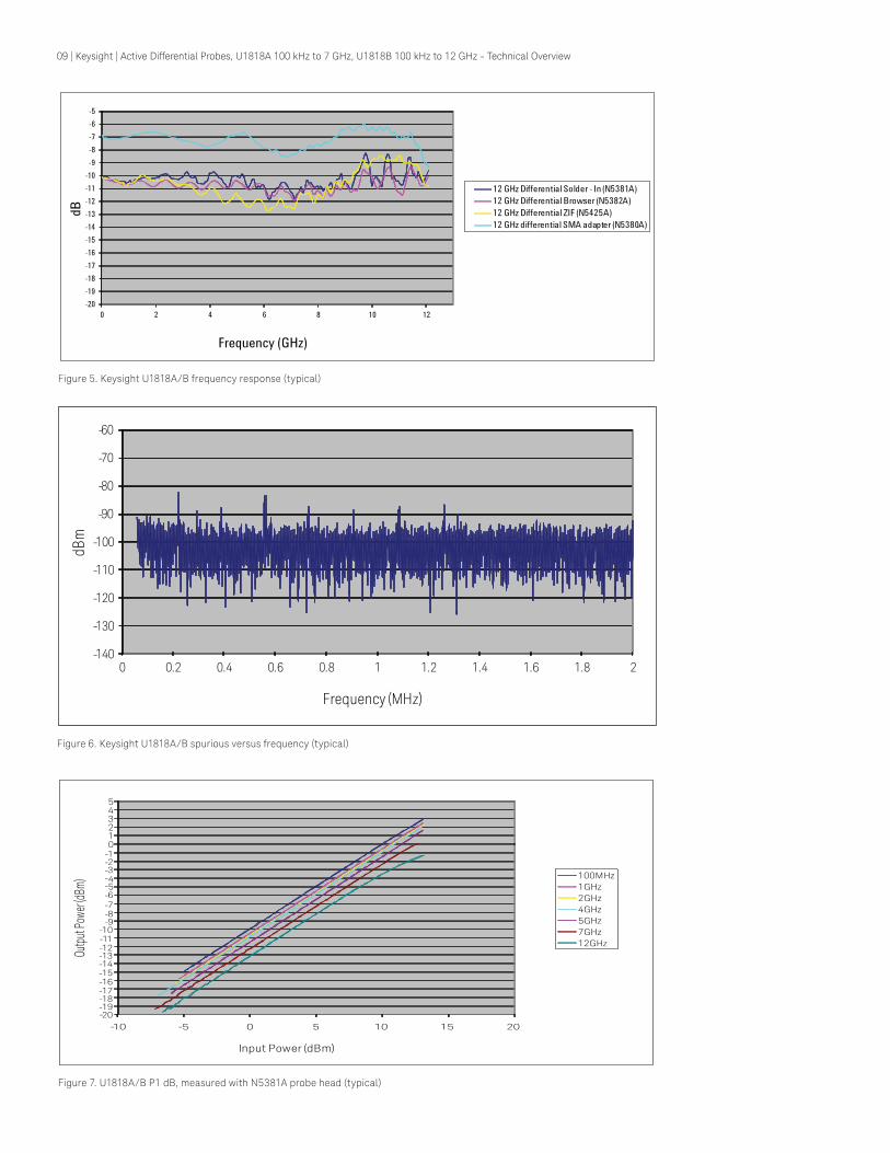
-20-19-18-17-16-15-14-13-12-11-10-9-8-7-6-5
0 2 4 6 8 10 12
dB
Frequency (GHz)
12 GHz Differential Solder - In (N5381A)12 GHz Differential Browser (N5382A)12 GHz Differential ZIF (N5425A)12 GHz differential SMA adapter (N5380A)
Figure 5. Keysight U1818A/B frequency response (typical)
-140
-130
-120
-110
-100
-90
-80
-70
-60
0 0.2 0.4 0.6 0.8 1 1.2 1.4 1.6 1.8 2
dBm
Frequency (MHz)
Figure 6. Keysight U1818A/B spurious versus frequency (typical)
-20-19-18-17-16-15-14-13-12-11-10
-9-8-7-6-5-4-3-2-1012345
- -10 5 0 5 10 15 20
Outpu
t Pow
er (dB
m)
Input Power (dBm)
100MHz1GHz2GHz4GHz5GHz7GHz12GHz
Figure 7. U1818A/B P1 dB, measured with N5381A probe head (typical)

10 | Keysight | Active Differential Probes, U1818A 100 kHz to 7 GHz, U1818B 100 kHz to 12 GHz - Technical Overview
-12-11-10-9-8-76
-5-4-3-2-1012345678
-5 -4 -3 2 1 0 1 2 3 4 5 6 7 8 9 10 11 12 13 14 15
Pin
(dBm
)
Pout (dBm)
100 MHz
1 GHz
2 GHz
4 GHz
5 GHz
7 GHz
12 GHz
-
- -
Figure 8. U1818A/B P1 dB, measured with N5380A probe head (typical)
-165
-160
-155
-150
-145
-140
-135
-130
-3 2 7 12
dBm
/Hz
Frequency (GHz)
Noise spectral density
12 GHz Differential solder -In (N5381A)12 GHz Differential Browser (N5382A)12 GHz Differential SMA Adapter (N5380A)PSA NoiseFloor with 0dB attenuation
Figure 9. U1818A/B noise spectral density versus frequency (typical)

11 | Keysight | Active Differential Probes, U1818A 100 kHz to 7 GHz, U1818B 100 kHz to 12 GHz - Technical Overview
Figure 10. N5381A and N5382A probe heads input impedance versus frequency (typical)
Figure 11. N5425A probe heads input impedance versus frequency (typical)

12 | Keysight | Active Differential Probes, U1818A 100 kHz to 7 GHz, U1818B 100 kHz to 12 GHz - Technical Overview
Mechanical Dimension*
U1818A/B
Mechanical Dimension Figure 12
Connector Type N-Type (m)
Weight 0.170 kg ( 0.236 lb)
Shipping Weight 1.135 kg ( 2.502 lb)
*Dimensions are in mm [inches] nominal, unless otherwise specified
Figure 12. U1818A/B mechanical dimensions
Ordering Information1
U1818A 100 kHz to 7 GHz active differential probeU1818B 100 kHz to 12 GHz active differential probe
– Option 001 Cable assembly – power probe cable – Option 002 Cable assembly – banana plug
Probe HeadE2695A Differential SMA probe head for InfiniiMax probeN5380A InfiniiMax II 12 GHz differential SMA adapterN5381A 12 GHz InfiniiMax differential solder-in probe head N5382A InfiniiMax II 12 GHz differential browserN5425A 12 GHz InfiniiMax ZIF-solder-in probe headN5426A 12 GHz InfiniiMax ZIF Tip –kit of 10
Related Accessories11852B Minimum loss attenuator padE2676A 6 GHz InfiniiMax single-end browser probe headN2784A 1-arm probe positionerN2785A 2-arm probe positionerN2787A 3D probe positionerN2880A In-line attenuator kitN2881A DC blocking capacitorN5450A InfiniiMax extreme temperature cable extension
Recommended Power SuppliesE3620A 50 W Dual Output Power Supply For a complete list of power supplies go towww.keysight.com/find/DCPowerSupplies
Related Literature
High Frequency Probing Solutions for Time and Frequency Domain Applications, 5990-4387EN
1. The U1818A/B are shipped with a protective casing

13 | Keysight | Active Differential Probes, U1818A 100 kHz to 7 GHz, U1818B 100 kHz to 12 GHz - Technical Overview
This information is subject to change without notice.© Keysight Technologies, 2017Published in USA, December 1, 20175990-4148ENwww.keysight.com
www.keysight.com/find/mtawww.keysight.com/find/RFprobes
myKeysightwww.keysight.com/find/mykeysightA personalized view into the information most relevant to you.
http://www.keysight.com/find/emt_product_registrationRegister your products to get up-to-date product information and find warranty information.
Keysight Serviceswww.keysight.com/find/serviceKeysight Services can help from acquisition to renewal across your instrument’s lifecycle. Our comprehensive service offerings—one-stop calibration, repair, asset management, technology refresh, consulting, training and more—helps you improve product quality and lower costs.
Keysight Assurance Planswww.keysight.com/find/AssurancePlansUp to ten years of protection and no budgetary surprises to ensure your instruments are operating to specification, so you can rely on accurate measurements.
Keysight Channel Partnerswww.keysight.com/find/channelpartnersGet the best of both worlds: Keysight’s measurement expertise and product breadth, combined with channel partner convenience.
Evolving Since 1939Our unique combination of hardware, software, services, and people can help you reach your next breakthrough. We are unlocking the future of technology. From Hewlett-Packard to Agilent to Keysight.
For more information on Keysight Technologies’ products, applications or services, please contact your local Keysight office. The complete list is available at:www.keysight.com/find/contactus
Americas Canada (877) 894 4414Brazil 55 11 3351 7010Mexico 001 800 254 2440United States (800) 829 4444
Asia PacificAustralia 1 800 629 485China 800 810 0189Hong Kong 800 938 693India 1 800 11 2626Japan 0120 (421) 345Korea 080 769 0800Malaysia 1 800 888 848Singapore 1 800 375 8100Taiwan 0800 047 866Other AP Countries (65) 6375 8100
Europe & Middle EastAustria 0800 001122Belgium 0800 58580Finland 0800 523252France 0805 980333Germany 0800 6270999Ireland 1800 832700Israel 1 809 343051Italy 800 599100Luxembourg +32 800 58580Netherlands 0800 0233200Russia 8800 5009286Spain 800 000154Sweden 0200 882255Switzerland 0800 805353
Opt. 1 (DE)Opt. 2 (FR)Opt. 3 (IT)
United Kingdom 0800 0260637
For other unlisted countries:www.keysight.com/find/contactus(BP-9-7-17)
DEKRA CertifiedISO9001 Quality Management System
www.keysight.com/go/qualityKeysight Technologies, Inc.DEKRA Certified ISO 9001:2015Quality Management System


