20
Keysight Technologies Innovative Passive Intermodulation (PIM) and S-parameter Measurement Solution with the ENA Application Note
| Date post: | 17-Nov-2018 |
| Category: |
Documents |
| Upload: | nguyendieu |
| View: | 235 times |
| Download: | 1 times |
Keysight TechnologiesInnovative Passive Intermodulation (PIM) and S-parameter Measurement Solution with the ENA
Application Note

Introduction
Passive intermodulation (PIM) is a form of intermodulation distortion that occurs in passive compo-
nents such as antennas, cables, connectors, or duplexers with two or more high-power input signals.
PIM becomes a big issue for modern communication industry. PIM from these passive components
in the transmitter path falls in to the receiver path; thus the unwanted signals can increase the noise
level of the receiver path that degrades quality of the wireless communication system. In order to
comply with the regulations, PIM of passive components test becomes more important nowadays.
This application note introduces the test system that combines PIM and S-parameter measurements
of passive components by using the vector network analyzer (VNA). The innovative solution with Key-
sight E5072A ENA Series Network Analyzer1 is introduced in the document that provides Fast, Flexible
and Accurate measurement capabilities. It is a higher-performance and cost-effective solution that
can replace the conventional PIM test solutions.
1 See the E5072A technical overview, product number 5990-8004EN for more detail about the
E5072A.
3
Table of Contents
Introduction .........................................................................2
Passive Intermodulation (PIM) ........................................3
Measuring PIM ...................................................................4
Challenges with current solutions ..................................5
Solution with the VNA ......................................................6
Benefits and key features ................................................6
- Flexible configurations ................................................7
- Fast measurements .....................................................8
- Accurate measurements .............................................8
Measurement Example .....................................................9
– System configuration ..................................................9
– PIM measurement software ...................................10
– Step-by-step guide for measuring PIM .................10
– Step 1 Setup of test configuration ....................11
– Step 2 Setup of measurement parameters ......11
– Step 3 User calibration ........................................12
– Step 4 Measurement ...........................................17
– Measurement result .................................................18
Summary ............................................................................18
Appendix A. Block diagram of the E5072A .................19
Passive Intermodulation (PIM)
PIM is an unwanted signal created by the mixing of two
or more RF signals, caused by nonlinearity of the passive
components in the RF path such as antennas, cables or
connectors. PIM product is the result of high power tones
mixing induced by ferromagnetic materials, junctions of
dissimilar metals, metal-oxide junctions, contaminated
junctions and loose RF connectors.
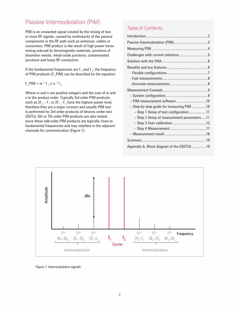
If the fundamental frequencies are f 1 and f 2, the frequency
of PIM products (F_PIM) can be described by the equation:
F_PIM = m * f 1 ± n * f 2
Where m and n are positive integers and the sum of m and
n is the product order. Typically 3rd order PIM products
such as 2f 2 – f 1 or 2f 1 - f 2 have the highest power level,
therefore they are a major concern and usually PIM test
is performed for 3rd order products of devices under test
(DUTs). 5th or 7th order PIM products are also tested,
since these odd-order PIM products are typically close to
fundamental frequencies and may interfere in the adjacent
channels for communication (Figure 1).
Figure 1. Intermodulation signals
Frequencyf1 f23f1-2f24f1-3f2
Am
plit
ude
3 rd5 th7 th 3 rd 5 th 7 th
2f1-f2 2f2-f1 3f2-2f1 4f2-3f1
dBc
Carrier
IntermodulationIntermodulation
4
PIM is normally specified in terms of dBm and dBc, where dBm
is a measure of the absolute value of PIM products and dBc is a
measure of dB relative to a specified fundamental power level.
For example, typical 20 watts or +43 dBm is input power level
of two main signals and the PIM product created in DUT is -110
dBm, the PIM product is –153 dBc. Acceptable levels of PIM
products are extremely low, in the range of –100 to –120 dBm
with two fundamental tones at +43 dBm.
Figure 2 shows a typical block diagram of the front-end of
wireless communication systems. Although filtering can reduce
unwanted signals generated by power amplifiers in the trans-
mitter path, PIM products from passive components such as
antennas, cables or connectors in the RF signal path can not be
filtered. The unwanted PIM products in the transmitter (Tx) path
falls into the receiver (Rx) path, increases the noise level and
degrades the quality of wireless communication. It is important
to design and install low PIM passive components to guarantee
the requirements or specifications of the systems.
Measuring PIM
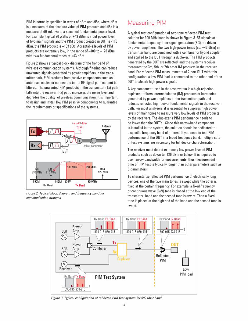
A typical test configuration of two-tone reflected PIM test
solution for 900 MHz band is shown in Figure 3. RF signals at
fundamental frequency from signal generators (SG) are driven
by power amplifiers. The two high-power tones (i.e. +43 dBm) in
transmitter band are combined with a combiner or hybrid coupler
and applied to the DUT through a duplexer. The PIM products
generated by the DUT are reflected, and the systems receiver
measures the 3rd, 5th, or 7th order IM products in the receiver
band. For reflected PIM measurements of 2-port DUT with this
configuration, a low PIM load is connected to the other end of the
DUT to absorb high-power signals.
A key component used in the test system is a high-rejection
duplexer. It filters intermodulation (IM) products or harmonics
generated by power amplifiers in the transmitter path and
reduces reflected high-power fundamental signals in the receiver
path. For most analyzers, it is essential to suppress high power
levels of main tones to measure very low levels of PIM products
by the receivers. The duplexer’s PIM performance needs to
be lower than the DUT’s . Since this narrowband component
is installed in the system, the solution should be dedicated to
a specific frequency band of interest. If you need to test PIM
performance of the DUT in a broad frequency band, multiple sets
of test systems are necessary for full device characterization.
The receiver must detect extremely low power level of PIM
products such as down to -120 dBm or below. It is required to
use narrow bandwidth for measurements, thus measurement
time of PIM test is typically longer than other parameters such as
S-parameters.
To characterize reflected PIM performance of electrically long
devices, one of the two main tones is swept while the other is
fixed at the certain frequency. For example, a fixed frequency
or continuous wave (CW) tone is placed at the low end of the
transmitter band and the second tone is swept. Then a fixed
tone is placed at the high end of the band and the second tone is
swept.
Figure 2. Typical block diagram and frequency band for
communication systems
Figure 3. Typical configuration of reflected PIM test system for 900 MHz band
Tx
Rx
Duplexer
Antennai.e. +43 dBm
(20 W)
890M 915M 930M 960MHz
Tx Band
930 MHz 950 MHz
910 MHz
Rx Band
cable, connector
890 MHzIM5 IM3 IM3
970 MHz
Duplexer
Power Amp
Power AmpSG1
SG2
Receiver
V
Tx
RxReflected
PIM
PIM Test System
DUT
Low
PIM load
Combiner
f890-915
Tx BandRx Band
930-915f
890-915
Tx BandRx Band
930-915f
890-915
Tx BandRx Band
930-915f
890-915
Tx BandRx Band
930-915f

5
Challenges with current solutions
Today PIM testing is performed with either dedicated
standalone PIM analyzers or rack and stack system
solutions with the combination of generators, receivers
and additional components. There are measurement
challenges with current PIM test solutions to improve
productivity of PIM measurements.
1. Total throughput With the growing demand of the PIM testing, it
is always required to reduce measurement time.
However, when using multiple instruments for PIM
measurements, all the measurement instruments in
the test system are controlled by a system controller
and measurements have to be synchronized for each
data point. Therefore total measurement process
takes long time to complete especially for swept-
frequency PIM measurements with a lot of data
points.
S-parameters such as return loss or insertion loss are
important parameters for passive components, and
both PIM and S-parameters measurements need to be
tested in the final stage of productions. Conventional
test systems require the set of a VNA and several
PIM measurement solutions dedicated for individual
frequency bands. When different test stations are
used for total device characterization, the time
required to connect and disconnect the components
can be greater than the actual testing time.
2. Multiband test Many of PIM analyzers are designed for a specific
frequency band due to included narrowband
components such as a duplexer. In order to test
the DUT that supports multiband operation, it is
necessary to purchase additional analyzers for other
frequency bands of interest. Overall cost of test
systems with multiple instruments becomes very
expensive needed for maintenance, calibration and
repair.
3. Calibration of power levels Power levels of PIM products are really sensitive to
input power level of fundamental tones, therefore it
is highly recommended to calibrate the power levels
of main tones for accurate PIM measurements.
However, most of PIM test analyzers available in the
market do not offer any power calibration method
that can be performed by operators, so you have
to rely on the periodic calibration and performance
verification provided by equipment vendors that are
usually performed once a year. Users need extra
margin/guard band on their measurement limits of
DUTs when considering measurement errors in the
analyzers such as temperature drift which power
amplifiers. User calibration methods must be offered
for designers and manufacturers who want to have a
good production yield of their components.
6
Solution with the VNA
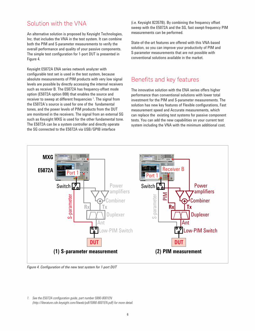
An alternative solution is proposed by Keysight Technologies,
Inc. that includes the VNA in the test system. It can combine
both the PIM and S-parameter measurements to verify the
overall performance and quality of your passive components.
The simple test configuration for 1-port DUT is presented in
Figure 4.
Keysight E5072A ENA series network analyzer with
configurable test set is used in the test system, because
absolute measurements of PIM products with very low signal
levels are possible by directly accessing the internal receivers
such as receiver B. The E5072A has frequency-offset mode
option (E5072A option 008) that enables the source and
receiver to sweep at different frequencies 1. The signal from
the E5072A’s source is used for one of the fundamental
tones, and the power levels of PIM products from the DUT
are monitored in the receivers. The signal from an external SG
such as Keysight MXG is used for the other fundamental tone.
The E5072A can be a system controller and directly operate
the SG connected to the E5072A via USB/GPIB interface
(i.e. Keysight 82357B). By combining the frequency offset
sweep with the E5072A and the SG, fast swept-frequency PIM
measurements can be performed.
State-of-the-art features are offered with this VNA-based
solution, so you can improve your productivity of PIM and
S-parameter measurements that are not possible with
conventional solutions available in the market.
Beneits and key features
The innovative solution with the ENA series offers higher
performance than conventional solutions with lower total
investment for the PIM and S-parameter measurements. The
solution has new key features of Flexible configurations, Fast
measurement speed and Accurate measurements, which
can replace the existing test systems for passive component
tests. You can add the new capabilities on your current test
system including the VNA with the minimum additional cost.
Figure 4. Configuration of the new test system for 1-port DUT
1. See the E5072A configuration guide, part number 5990-8001EN
(http://literature.cdn.keysight.com/litweb/pdf/5990-8001EN.pdf) for more detail.
(1) S-parameter measurement (2) PIM measurement
DUT
Rx Tx
Ant
Duplexer
PIM
Low-PIM Switch
Poweramplifiers
Combiner
Switch
Port 1
S-p
aram
eter
Receiver B
DUT
Rx Tx
Ant
Duplexer
Low-PIM Switch
Poweramplifiers
Combiner
Switch
E5072A
MXG
Port 1
S-p
aram
eter

7
1. Flexible conigurationsEspecially for PIM measurements of passive
components, the time required to connect and
disconnect the components can become greater. With
the VNA-based solution, both PIM and S-parameter
measurements can be performed without changing
physical connections of the DUT (Figure 4). It reduces
the time you spend in connecting and disconnecting
a DUT and significantly improves your overall test
throughput.
With the demanding needs of PIM measurements
for wireless communication industries, every passive
component in the RF signal path needs to be tested,
which include 1-port antennas, 2-port cables and
connectors, or 3-port duplexers. Some standalone PIM
analyzers are specifically designed for reflected PIM
measurements of 1-port DUT, therefore the analyzers
with the internal duplexer are not best suited for PIM
tests of 3-port duplexers.
Since the new solution consists of the analyzers and
individual components, you can expand your test
capabilities easily with alternative configurations for
any types of components. You can measure 3-port DUT
such as a duplexer with the minimum change in the
test configuration (Figure 5).
Because of the narrowband duplexer included in the
standalone PIM analyzers, PIM measurements of
passive components with multiband operation such
as BTS antennas can be headache for test engineers.
Multiple analyzers and sequential measurements are
required for total characterization of a single DUT.
Since the E5072A and SG operate in a broad frequency
range depending on selected options, the broadband
PIM test solutions can be configured by using the
filter/duplexer module and switch matrix to select the
frequency band. (Figure 6)
The test configuration ca be optimized with flexible
setup to meet your future demands of component tests.
Figure 5. Flexible PIM test configurations for 1-port and 3-port DUT
Figure 6. Expansion of the test capabilities for multiband DUT
S-parameter test PIM test(s)PIM & S-parameter test
ENA-based solution
PIM Analyzer #1(Band 1)
PIM Analyzer #2(Band 2)
PIM Analyzer #3(Band 3)
VNA
:
DUTPA DET PIM OUT
RF OUT
J1
J3
J2 J1 J2
J3
SW1 PIM SW1
J1
J3
J2
SW2
E5072A
MXG
PA module
Switch matrix
Filter modules(Band 1, 2,)
DUT
(1) 1-port DUT (i.e. Antenna)
DUT
Rx Tx
Ant
Duplexer
Poweramplifiers
Combiner
E5072A
MXG
Port 1Receiver B
(2) 3-port DUT (i.e. Duplexer)
Low PIMload
Rx Tx
Ant
DuplexerUnder test
Poweramplifiers
Combiner
Port 1Receiver B
8
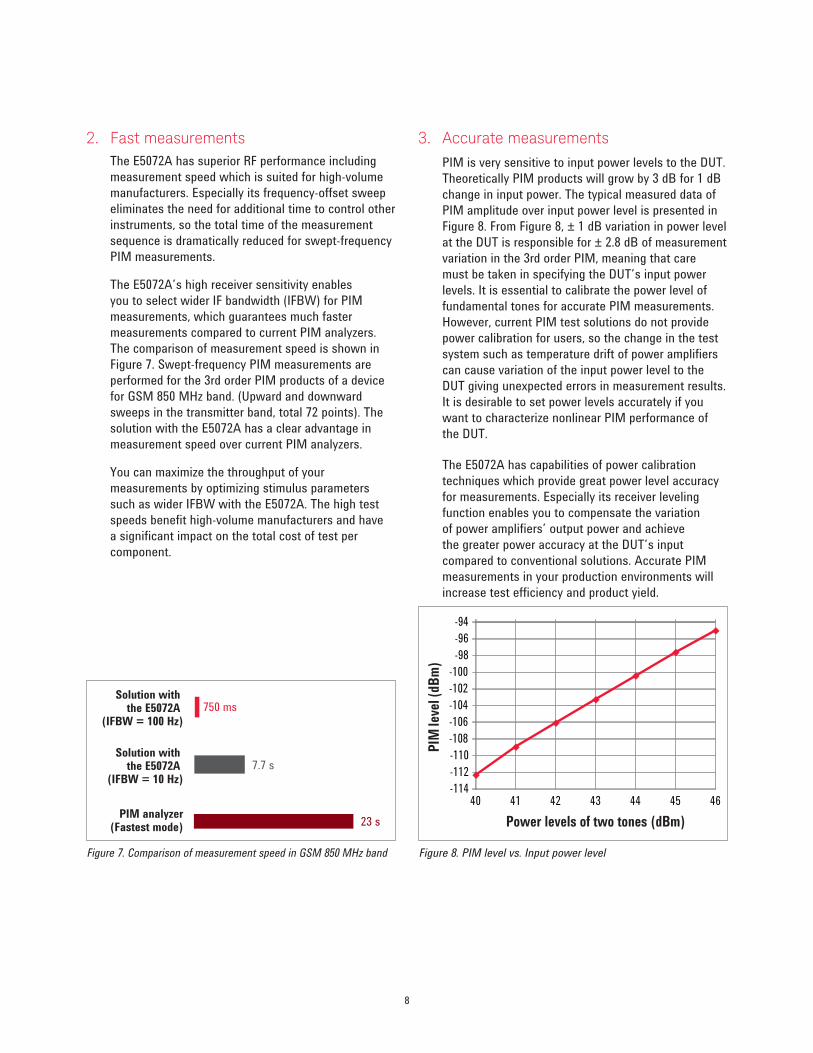
2. Fast measurements
The E5072A has superior RF performance including
measurement speed which is suited for high-volume
manufacturers. Especially its frequency-offset sweep
eliminates the need for additional time to control other
instruments, so the total time of the measurement
sequence is dramatically reduced for swept-frequency
PIM measurements.
The E5072A’s high receiver sensitivity enables
you to select wider IF bandwidth (IFBW) for PIM
measurements, which guarantees much faster
measurements compared to current PIM analyzers.
The comparison of measurement speed is shown in
Figure 7. Swept-frequency PIM measurements are
performed for the 3rd order PIM products of a device
for GSM 850 MHz band. (Upward and downward
sweeps in the transmitter band, total 72 points). The
solution with the E5072A has a clear advantage in
measurement speed over current PIM analyzers.
You can maximize the throughput of your
measurements by optimizing stimulus parameters
such as wider IFBW with the E5072A. The high test
speeds benefit high-volume manufacturers and have
a significant impact on the total cost of test per
component.
3. Accurate measurements
PIM is very sensitive to input power levels to the DUT.
Theoretically PIM products will grow by 3 dB for 1 dB
change in input power. The typical measured data of
PIM amplitude over input power level is presented in
Figure 8. From Figure 8, ± 1 dB variation in power level
at the DUT is responsible for ± 2.8 dB of measurement
variation in the 3rd order PIM, meaning that care
must be taken in specifying the DUT’s input power
levels. It is essential to calibrate the power level of
fundamental tones for accurate PIM measurements.
However, current PIM test solutions do not provide
power calibration for users, so the change in the test
system such as temperature drift of power amplifiers
can cause variation of the input power level to the
DUT giving unexpected errors in measurement results.
It is desirable to set power levels accurately if you
want to characterize nonlinear PIM performance of
the DUT.
The E5072A has capabilities of power calibration
techniques which provide great power level accuracy
for measurements. Especially its receiver leveling
function enables you to compensate the variation
of power amplifiers’ output power and achieve
the greater power accuracy at the DUT’s input
compared to conventional solutions. Accurate PIM
measurements in your production environments will
increase test efficiency and product yield.
Figure 7. Comparison of measurement speed in GSM 850 MHz band Figure 8. PIM level vs. Input power level
PIM analyzer(Fastest mode)
Solution with the E5072A
(IFBW = 10 Hz)
23 s
750 msSolution with
the E5072A (IFBW = 100 Hz)
7.7 s
Power levels of two tones (dBm)
PIM
leve
l (d
Bm
)
-114
-112
-110
-108
-106
-104
-102
-100
-98
-96
-94
40 41 42 43 44 45 46
9
Measurement Example
A measurement example with the ENA-based solution will
be introduced for 1-port DUT that requires swept-frequency
PIM measurement as well as S-parameter (i.e. return
loss) measurements. The following instructions will focus
on measurement setup of PIM measurements. For basic
S-parameter measurements using the E5072A, details can be
found in the E5072A help at:
http://ena.tm.keysight.com/e5072a/manuals/webhelp/eng/
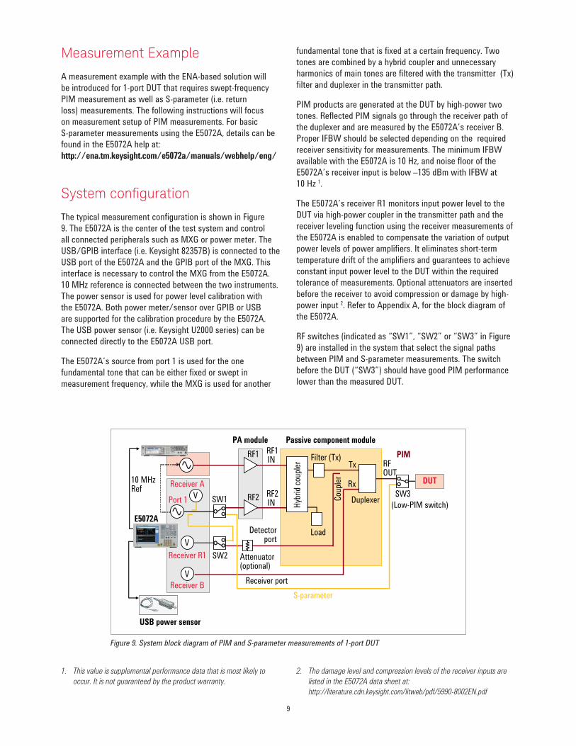
System coniguration
The typical measurement configuration is shown in Figure
9. The E5072A is the center of the test system and control
all connected peripherals such as MXG or power meter. The
USB/GPIB interface (i.e. Keysight 82357B) is connected to the
USB port of the E5072A and the GPIB port of the MXG. This
interface is necessary to control the MXG from the E5072A.
10 MHz reference is connected between the two instruments.
The power sensor is used for power level calibration with
the E5072A. Both power meter/sensor over GPIB or USB
are supported for the calibration procedure by the E5072A.
The USB power sensor (i.e. Keysight U2000 series) can be
connected directly to the E5072A USB port.
The E5072A’s source from port 1 is used for the one
fundamental tone that can be either fixed or swept in
measurement frequency, while the MXG is used for another
fundamental tone that is fixed at a certain frequency. Two
tones are combined by a hybrid coupler and unnecessary
harmonics of main tones are filtered with the transmitter (Tx)
filter and duplexer in the transmitter path.
PIM products are generated at the DUT by high-power two
tones. Reflected PIM signals go through the receiver path of
the duplexer and are measured by the E5072A’s receiver B.
Proper IFBW should be selected depending on the required
receiver sensitivity for measurements. The minimum IFBW
available with the E5072A is 10 Hz, and noise floor of the
E5072A’s receiver input is below –135 dBm with IFBW at
10 Hz 1.
The E5072A’s receiver R1 monitors input power level to the
DUT via high-power coupler in the transmitter path and the
receiver leveling function using the receiver measurements of
the E5072A is enabled to compensate the variation of output
power levels of power amplifiers. It eliminates short-term
temperature drift of the amplifiers and guarantees to achieve
constant input power level to the DUT within the required
tolerance of measurements. Optional attenuators are inserted
before the receiver to avoid compression or damage by high-
power input 2. Refer to Appendix A, for the block diagram of
the E5072A.
RF switches (indicated as “SW1”, “SW2” or “SW3” in Figure
9) are installed in the system that select the signal paths
between PIM and S-parameter measurements. The switch
before the DUT (“SW3”) should have good PIM performance
lower than the measured DUT.
Figure 9. System block diagram of PIM and S-parameter measurements of 1-port DUT
1. This value is supplemental performance data that is most likely to
occur. It is not guaranteed by the product warranty.
2. The damage level and compression levels of the receiver inputs are
listed in the E5072A data sheet at:
http://literature.cdn.keysight.com/litweb/pdf/5990-8002EN.pdf
DuplexerPort 1
V
Tx
Rx
Cou
pler
Detectorport
Receiver port
10 MHzRef
RF1
RF2
Receiver B
Receiver R1
USB power sensor
Passive component modulePA module
Filter (Tx)
Hyb
rid
coup
ler
Load
Attenuator(optional)
E5072A
V
Receiver A
V SW1
SW2
SW3
(Low-PIM switch)
DUT
S-parameter
PIMRFOUT
RF1IN
RF2IN
10
PIM measurement software
In most cases, measurement speed is not the only factor
in increasing throughput in testing. The time spent
connecting the devices to measurement instruments,
calibrating the instrument and setting up of the
measurement parameters is much longer than actual
measurement time. To accelerate time-to-market, you
need easy-to-use measurement software that guides you
through measurement procedures to minimize the setup
time.
A sample program of PIM measurement software for the
E5072A is available on Keysight website (www.keysight.
com/find/pim). The utility software sets up necessary
parameters on the E5072A. It also features a calibration
wizard that provides step-by-step instructions of power
calibration procedures for PIM measurements. The PIM
measurement software for the E5072A saves you a lot
of setup and calibration time and eliminates many of the
operator errors in measurement procedures.
The software runs in the E5072A’s Microsoft VBA Macro
Programming capability, and it controls all peripherals
connected to the E5072A without the use of additional
system software running on an external PC. As the
source code of this software is not password protected,
you can customize the software easily for your own PIM
measurements.
For more detail about the operation of the PIM
measurement software, refer to the operation guide
available at the website above.
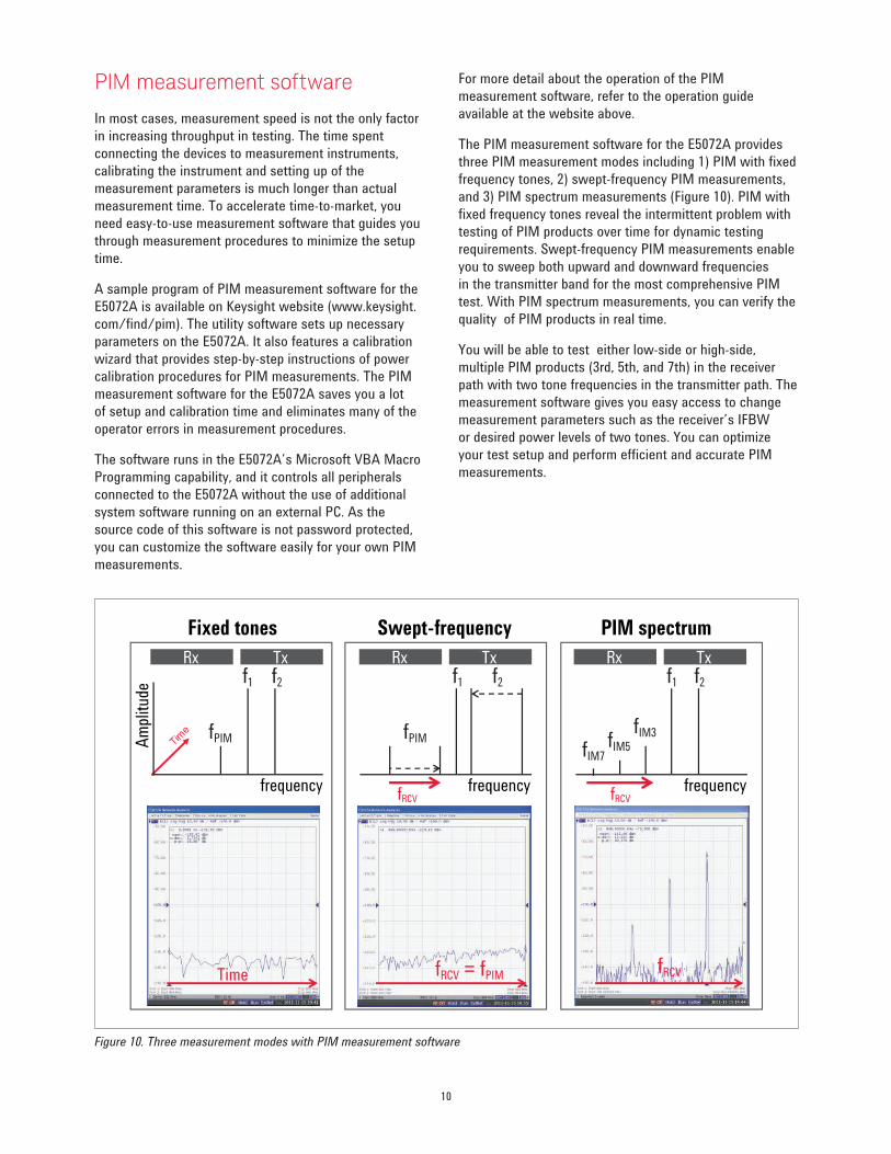
The PIM measurement software for the E5072A provides
three PIM measurement modes including 1) PIM with fixed
frequency tones, 2) swept-frequency PIM measurements,
and 3) PIM spectrum measurements (Figure 10). PIM with
fixed frequency tones reveal the intermittent problem with
testing of PIM products over time for dynamic testing
requirements. Swept-frequency PIM measurements enable
you to sweep both upward and downward frequencies
in the transmitter band for the most comprehensive PIM
test. With PIM spectrum measurements, you can verify the
quality of PIM products in real time.
You will be able to test either low-side or high-side,
multiple PIM products (3rd, 5th, and 7th) in the receiver
path with two tone frequencies in the transmitter path. The
measurement software gives you easy access to change
measurement parameters such as the receiver’s IFBW
or desired power levels of two tones. You can optimize
your test setup and perform efficient and accurate PIM
measurements.
Figure 10. Three measurement modes with PIM measurement software
TxRx TxRx TxRx
Fixed tones Swept-frequency PIM spectrum
Time
Am
plit
ude
frequencyfRCV
fRCV = fPIM
fPIM fPIM
fIM7fIM5
fIM3
f1 f2 f1 f2f1 f2
fRCV
fRCV
frequency frequency
11
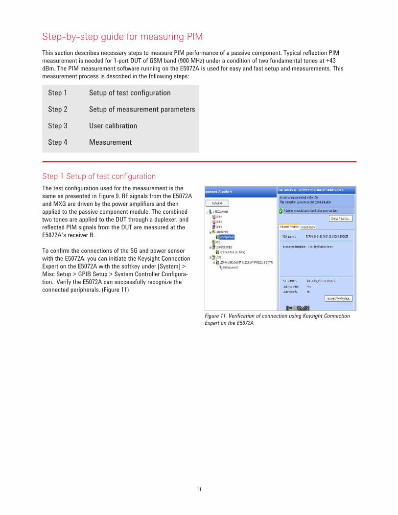
Step 1 Setup of test conigurationThe test configuration used for the measurement is the
same as presented in Figure 9. RF signals from the E5072A
and MXG are driven by the power amplifiers and then
applied to the passive component module. The combined
two tones are applied to the DUT through a duplexer, and
reflected PIM signals from the DUT are measured at the
E5072A’s receiver B.
To confirm the connections of the SG and power sensor
with the E5072A, you can initiate the Keysight Connection
Expert on the E5072A with the softkey under [System] >
Misc Setup > GPIB Setup > System Controller Configura-
tion.. Verify the E5072A can successfully recognize the
connected peripherals. (Figure 11)
Figure 11. Verification of connection using Keysight Connection
Expert on the E5072A
Step-by-step guide for measuring PIM
This section describes necessary steps to measure PIM performance of a passive component. Typical reflection PIM
measurement is needed for 1-port DUT of GSM band (900 MHz) under a condition of two fundamental tones at +43
dBm. The PIM measurement software running on the E5072A is used for easy and fast setup and measurements. This
measurement process is described in the following steps:
Step 1 Setup of test configuration
Step 2 Setup of measurement parameters
Step 3 User calibration
Step 4 Measurement
12
Step 3 User calibration
The calibration procedure is the important part of
measurements with the VNA and it is necessary to perform
power level calibrations before PIM measurements. If the
calibration is inaccurate, you will not measure the true PIM
performance of your DUT. The E5072A offers various power
calibration techniques for users to achieve more accurate
results. Unlike conventional solutions, you can perform
power level calibrations by the E5072A anytime you want,
when test environments such as system configurations are
changed.
Power calibrationPower calibration using a power meter / sensor connected
to the E5072A adjusts the E5072A’s output power to
achieve the desired power level at the calibration plane.
Power calibration transfers the accuracy of the power
sensor used and sets the power level at the calibration
plane within a specified tolerance.
Receiver calibrationReceiver calibration is necessary for absolute
measurements in dBm using the E5072A’s receivers. The
calibration mathematically removes frequency response
in the receiver path and adjusts the E5072A’s readings to
the same as the targeted power level calibrated by power
calibration. With the receiver calibration, it is possible to
achieve accurate absolute power measurements (in dBm)
with the E5072A.
Receiver levelingThe E5072A has receiver leveling function that uses the
receiver measurements to adjust the source power level
across a frequency band. Before each measurement
sweep, a variable number of background sweeps are
performed to repeatedly measure power at the receiver.
Those power measurements are then used to adjust
the E5072A’s source power level for providing targeted
leveled power at the DUT’s interface. The receiver
leveling function compensates temperature drift of power
amplifiers in real time, providing accurately leveled power
at the DUT during PIM measurements.
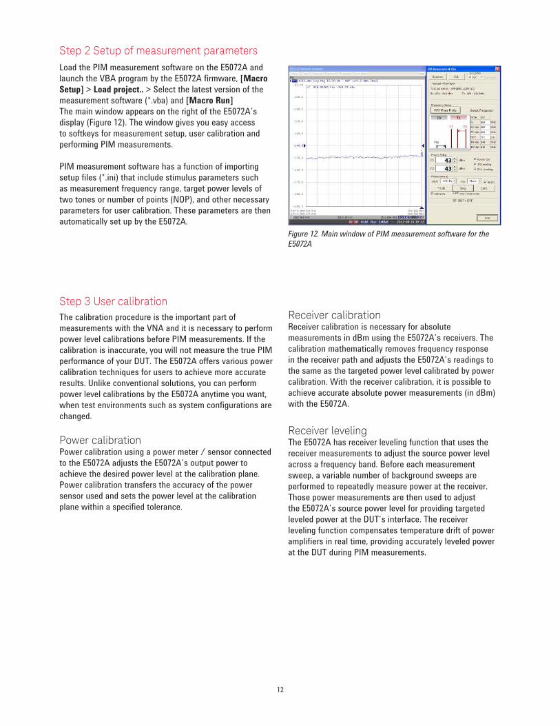
Step 2 Setup of measurement parameters
Load the PIM measurement software on the E5072A and
launch the VBA program by the E5072A firmware, [Macro
Setup] > Load project.. > Select the latest version of the
measurement software (*.vba) and [Macro Run]
The main window appears on the right of the E5072A’s
display (Figure 12). The window gives you easy access
to softkeys for measurement setup, user calibration and
performing PIM measurements.
PIM measurement software has a function of importing
setup files (*.ini) that include stimulus parameters such
as measurement frequency range, target power levels of
two tones or number of points (NOP), and other necessary
parameters for user calibration. These parameters are then
automatically set up by the E5072A.
Figure 12. Main window of PIM measurement software for the
E5072A
13
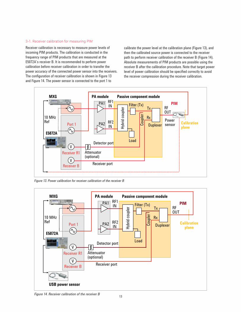
Figure 13. Power calibration for receiver calibration of the receiver B
Figure 14. Receiver calibration of the receiver B
3-1. Receiver calibration for measuring PIM
Receiver calibration is necessary to measure power levels of
incoming PIM products. The calibration is conducted in the
frequency range of PIM products that are measured at the
E5072A’s receiver B. It is recommended to perform power
calibration before receiver calibration in order to transfer the
power accuracy of the connected power sensor into the receivers.
The configuration of receiver calibration is shown in Figure 13
and Figure 14. The power sensor is connected to the port 1 to
calibrate the power level at the calibration plane (Figure 13), and
then the calibrated source power is connected to the receiver
path to perform receiver calibration of the receiver B (Figure 14).
Absolute measurements of PIM products are possible using the
receiver B after the calibration procedure. Note that target power
level of power calibration should be specified correctly to avoid
the receiver compression during the receiver calibration.
DuplexerPort 1
V
Tx
Rx
Cou
pler
Detector port
Receiver port
PA1
PA2
Receiver B
Receiver R1
Passive component modulePA moduleMXG
E5072A
Filter (Tx)
Hyb
rid
coup
ler
Load
Attenuator(optional)
V
PIMRFOUT
Calibrationplane
RF1IN
RF2IN
10 MHzRef Power
sensor
DuplexerPort 1
V
Tx
Rx
Cou
pler
Detector port
Receiver port
PA1
PA2
Receiver B
Receiver R1
Passive component modulePA moduleMXG
E5072A
Filter (Tx)
Hyb
rid c
oupl
er
Load
Attenuator(optional)
V
PIMRFOUT
Calibrationplane
RF1IN
RF2IN
10 MHzRef
USB power sensor
14
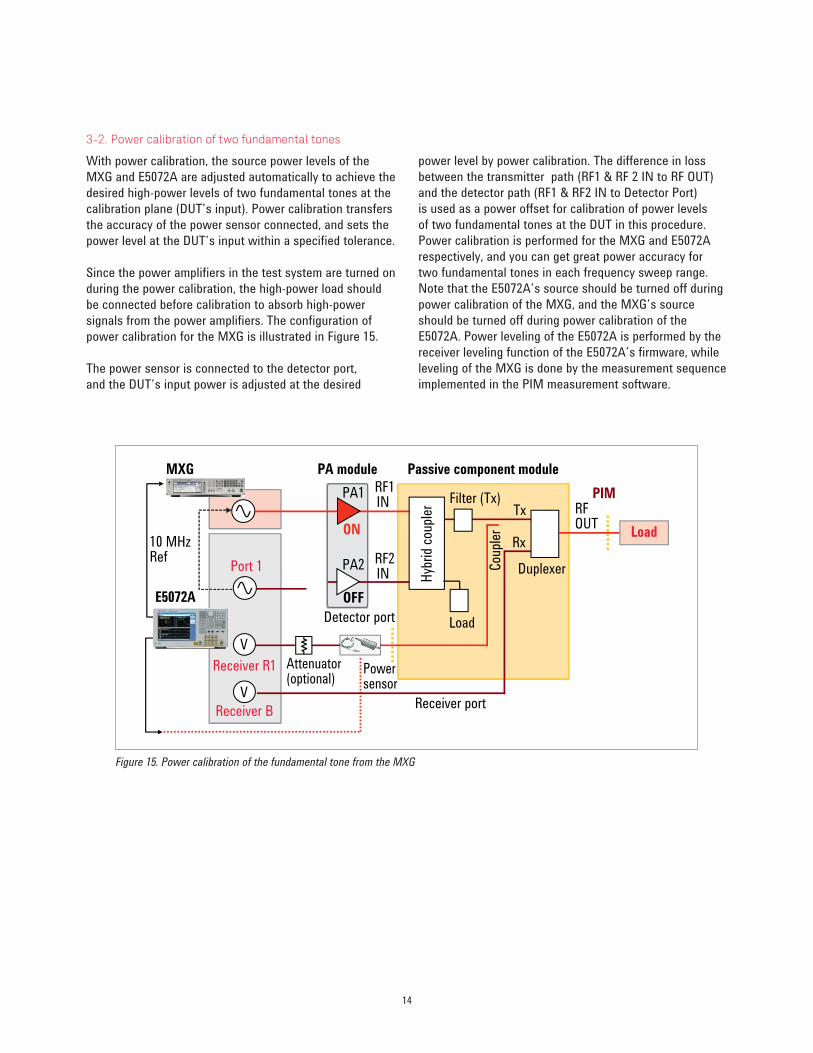
Figure 15. Power calibration of the fundamental tone from the MXG
3-2. Power calibration of two fundamental tones
With power calibration, the source power levels of the
MXG and E5072A are adjusted automatically to achieve the
desired high-power levels of two fundamental tones at the
calibration plane (DUT’s input). Power calibration transfers
the accuracy of the power sensor connected, and sets the
power level at the DUT’s input within a specified tolerance.
Since the power amplifiers in the test system are turned on
during the power calibration, the high-power load should
be connected before calibration to absorb high-power
signals from the power amplifiers. The configuration of
power calibration for the MXG is illustrated in Figure 15.
The power sensor is connected to the detector port,
and the DUT’s input power is adjusted at the desired
power level by power calibration. The difference in loss
between the transmitter path (RF1 & RF 2 IN to RF OUT)
and the detector path (RF1 & RF2 IN to Detector Port)
is used as a power offset for calibration of power levels
of two fundamental tones at the DUT in this procedure.
Power calibration is performed for the MXG and E5072A
respectively, and you can get great power accuracy for
two fundamental tones in each frequency sweep range.
Note that the E5072A’s source should be turned off during
power calibration of the MXG, and the MXG’s source
should be turned off during power calibration of the
E5072A. Power leveling of the E5072A is performed by the
receiver leveling function of the E5072A’s firmware, while
leveling of the MXG is done by the measurement sequence
implemented in the PIM measurement software.
DuplexerPort 1
V
Tx
Rx
Cou
pler
Detector port
Receiver port
PA1
PA2
Receiver B
Receiver R1
Passive component modulePA module
ON
OFF
MXG
E5072A
Filter (Tx)
Hyb
rid
coup
ler
Load
Attenuator(optional)
V
PIMRFOUT
RF1IN
RF2IN
10 MHzRef
Power sensor
Load

15
Figure 16. Receiver leveling - Power calibration in frequency range of MXG (RF1)
Figure 17. Receiver leveling - Receiver calibration in frequency range of MXG (RF1)
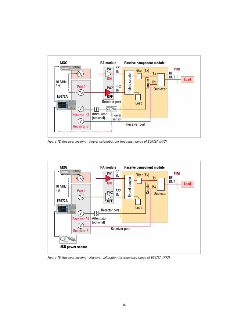
3-3. Leveling of two fundamental tones
The E5072A’s receiver leveling function is enabled to achieve
accurate power levels of two tones to the DUT’s input.
Background receiver measurements using the receiver R1 are
performed before each PIM measurement, and the source
power levels of the E5072A and MXG is adjusted automatically.
You can eliminate temperature drift and gain variation of the
power amplifiers. Also power linearity of high-power tones can
be improved by great receiver linearity provided by the E5072A.
Unexpected measurement errors of PIM results can be avoided
with the leveling feature.
Since the level accuracy of the receiver leveling depends on
the receiver’s absolute power measurement accuracy, power
calibration and receiver calibration for the receiver R1 should be
performed before enabling receiver leveling. These calibrations
are necessary for each frequency range of two fundamental tones
from the MXG and the E5072A. Power calibration and receiver
calibration require the E5072A’s source and receiver, so the
E5072A’s source from port 1 is connected to the power amplifier
(PA1) for the frequency range of the MXG during the calibration
procedure (Figure 16 & 17). And then the E5072A’s source is
connected to the power amplifier (PA2) for the frequency range of
the E5072A (Figure 18 & 19).
Power leveling of the two tones at the DUT’s input is achieved
by enabling receiver leveling with the E5072A. Power level
dependency of PIM products can be monitored, if you change the
input power level. Note that the fundamental power levels are
instantly adjusted by receiver leveling during measurements.
DuplexerPort 1
V
Tx
RxC
oupl
er
Detector port
Receiver port
PA1
PA2
Receiver B
Receiver R1
Passive component modulePA module
ON
OFF
MXG
E5072A
Filter (Tx)H
ybri
d co
uple
r
Load
Attenuator(optional)
V
PIMRFOUT
RF1IN
RF2IN
10 MHzRef
Power sensor
Load
USB power sensor
DuplexerPort 1
V
Tx
Rx
Cou
pler
Detector port
Receiver port
PA1
PA2
Receiver B
Receiver R1
Passive component modulePA module
ON
OFF
MXG
E5072A
Filter (Tx)
Hyb
rid
coup
ler
Load
Attenuator(optional)
V
PIMRFOUT
RF1IN
RF2IN
10 MHzRef
Load
16
Figure 18. Receiver leveling - Power calibration for frequency range of E5072A (RF2)
Figure 19. Receiver leveling - Receiver calibration for frequency range of E5072A (RF2)
DuplexerPort 1
V
Tx
Rx
Cou
pler
Detector port
Receiver port
PA1
PA2
Receiver B
Receiver R1
Passive component modulePA module
ON
OFF
MXG
E5072A
Filter (Tx)
Hyb
rid
coup
ler
Load
Attenuator(optional)
V
PIMRFOUT
RF1IN
RF2IN
10 MHzRef
Power sensor
Load
USB power sensor
DuplexerPort 1
V
Tx
Rx
Cou
pler
Detector port
Receiver port
PA1
PA2
Receiver B
Receiver R1
Passive component modulePA module
ON
OFF
MXG
E5072A
Filter (Tx)
Hyb
rid
coup
ler
Load
Attenuator(optional)
V
PIMRFOUT
RF1IN
RF2IN
10 MHzRef
Load
17
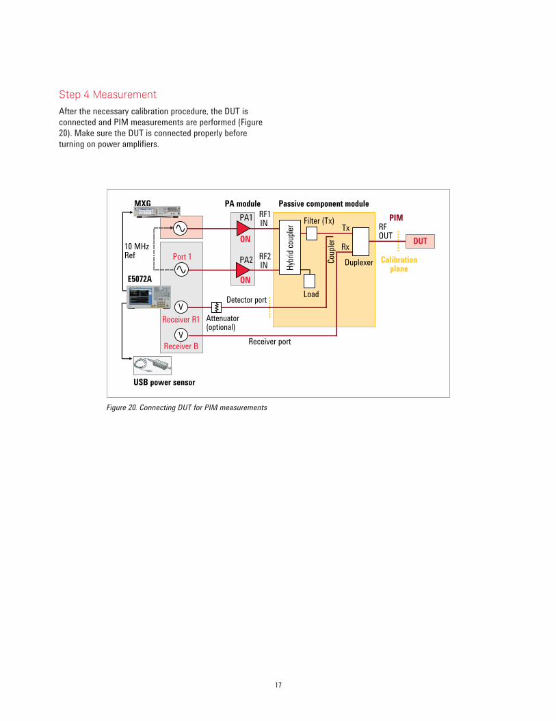
Figure 20. Connecting DUT for PIM measurements
Step 4 Measurement
After the necessary calibration procedure, the DUT is
connected and PIM measurements are performed (Figure
20). Make sure the DUT is connected properly before
turning on power amplifiers.
USB power sensor
DuplexerPort 1
V
Tx
Rx
Cou
pler
Detector port
Receiver port
PA1
PA2
Receiver B
Receiver R1
Passive component modulePA module
ON
ON
MXG
E5072A
Filter (Tx)
Hyb
rid
coup
ler
Load
Attenuator(optional)
V
PIMRFOUT
RF1IN
RF2IN
10 MHzRef
DUT
Calibrationplane
18
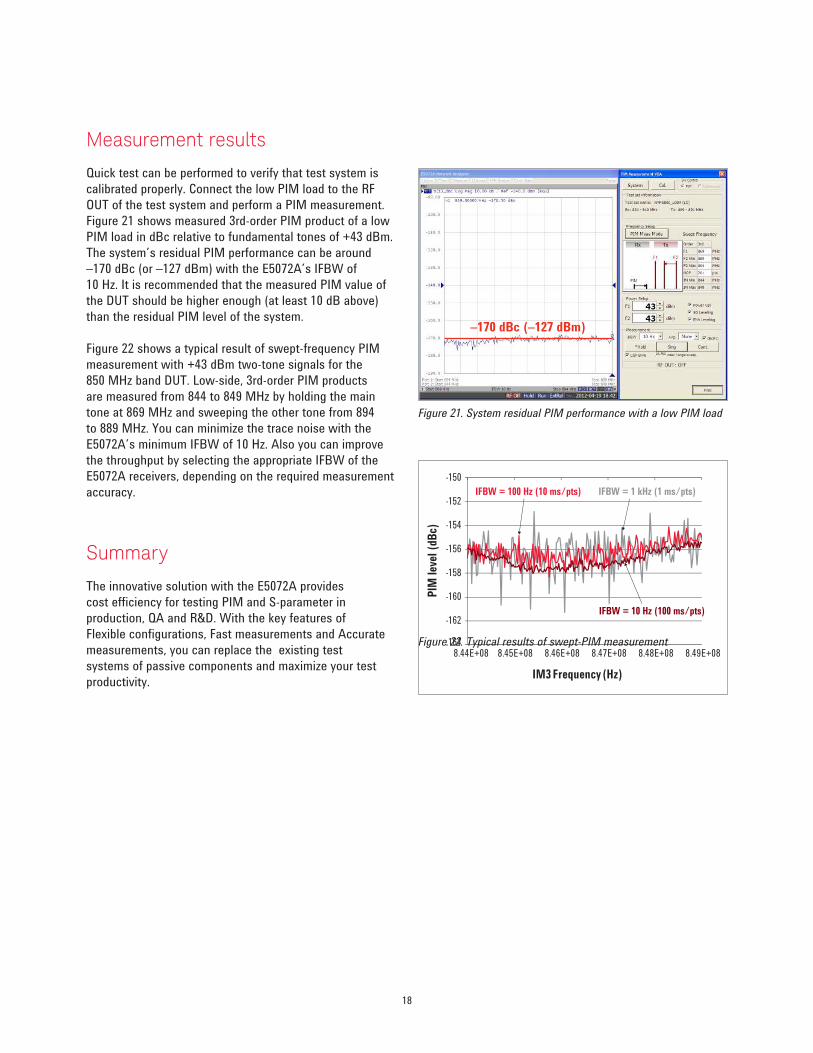
Measurement results
Quick test can be performed to verify that test system is
calibrated properly. Connect the low PIM load to the RF
OUT of the test system and perform a PIM measurement.
Figure 21 shows measured 3rd-order PIM product of a low
PIM load in dBc relative to fundamental tones of +43 dBm.
The system’s residual PIM performance can be around
–170 dBc (or –127 dBm) with the E5072A’s IFBW of
10 Hz. It is recommended that the measured PIM value of
the DUT should be higher enough (at least 10 dB above)
than the residual PIM level of the system.
Figure 22 shows a typical result of swept-frequency PIM
measurement with +43 dBm two-tone signals for the
850 MHz band DUT. Low-side, 3rd-order PIM products
are measured from 844 to 849 MHz by holding the main
tone at 869 MHz and sweeping the other tone from 894
to 889 MHz. You can minimize the trace noise with the
E5072A’s minimum IFBW of 10 Hz. Also you can improve
the throughput by selecting the appropriate IFBW of the
E5072A receivers, depending on the required measurement
accuracy.
Summary
The innovative solution with the E5072A provides
cost efficiency for testing PIM and S-parameter in
production, QA and R&D. With the key features of
Flexible configurations, Fast measurements and Accurate
measurements, you can replace the existing test
systems of passive components and maximize your test
productivity.
Figure 21. System residual PIM performance with a low PIM load
Figure 22. Typical results of swept-PIM measurement-164
-162
-160
-158
-156
-154
-152
-150
8.44E+08 8.45E+08 8.46E+08 8.47E+08 8.48E+08 8.49E+08
IFBW = 1 kHz (1 ms/pts)IFBW = 100 Hz (10 ms/pts)
IFBW = 10 Hz (100 ms/pts)
IM3 Frequency (Hz)
PIM
lev
el (
dBc)
–170 dBc (–127 dBm)
19
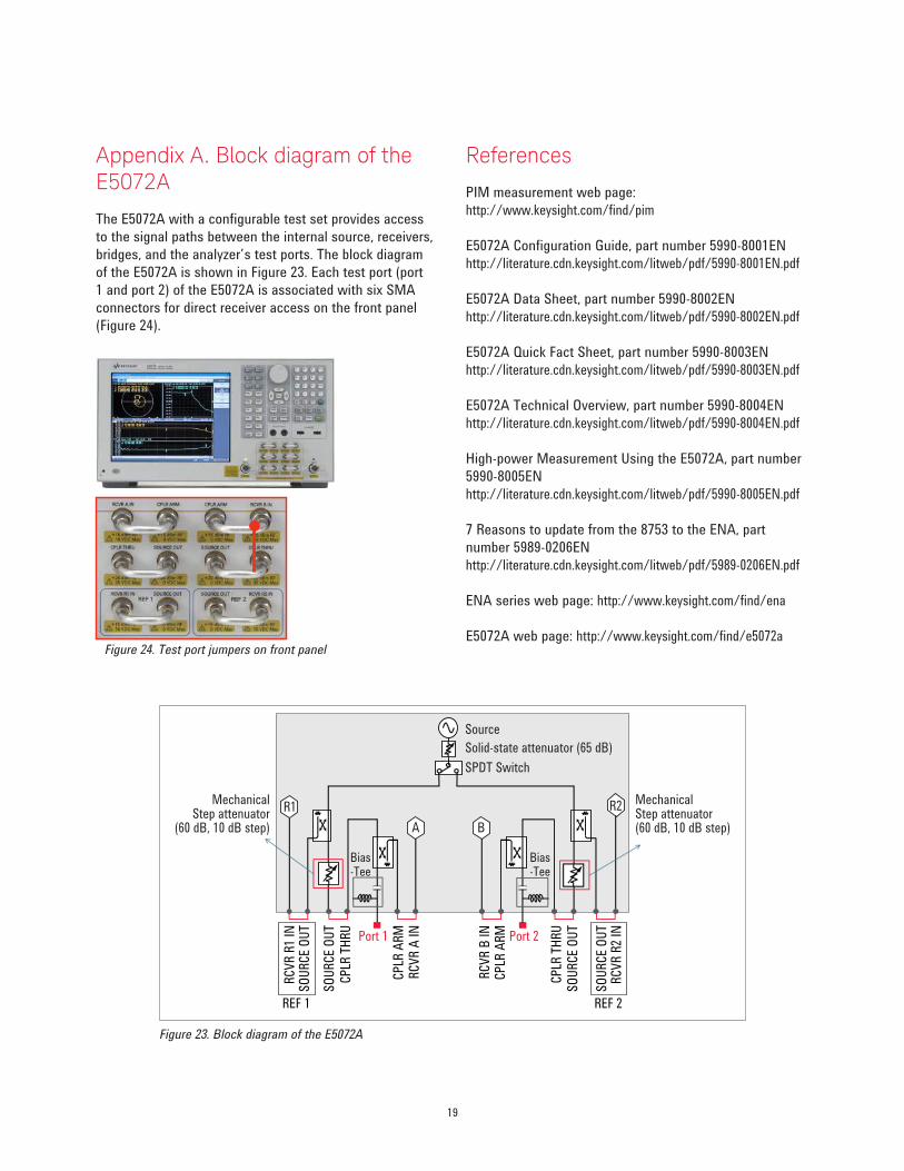
Figure 23. Block diagram of the E5072A
Appendix A. Block diagram of the E5072A
The E5072A with a configurable test set provides access
to the signal paths between the internal source, receivers,
bridges, and the analyzer’s test ports. The block diagram
of the E5072A is shown in Figure 23. Each test port (port
1 and port 2) of the E5072A is associated with six SMA
connectors for direct receiver access on the front panel
(Figure 24).
References
PIM measurement web page:
http://www.keysight.com/find/pim
E5072A Configuration Guide, part number 5990-8001EN
http://literature.cdn.keysight.com/litweb/pdf/5990-8001EN.pdf
E5072A Data Sheet, part number 5990-8002EN
http://literature.cdn.keysight.com/litweb/pdf/5990-8002EN.pdf
E5072A Quick Fact Sheet, part number 5990-8003EN
http://literature.cdn.keysight.com/litweb/pdf/5990-8003EN.pdf
E5072A Technical Overview, part number 5990-8004EN
http://literature.cdn.keysight.com/litweb/pdf/5990-8004EN.pdf
High-power Measurement Using the E5072A, part number
5990-8005EN
http://literature.cdn.keysight.com/litweb/pdf/5990-8005EN.pdf
7 Reasons to update from the 8753 to the ENA, part
number 5989-0206EN
http://literature.cdn.keysight.com/litweb/pdf/5989-0206EN.pdf
ENA series web page: http://www.keysight.com/find/ena
E5072A web page: http://www.keysight.com/find/e5072aFigure 24. Test port jumpers on front panel
R1
A
R2
B
Port 1 Port 2
RC
VR
R1
INS
OU
RC
E O
UT
CP
LR T
HR
U
CP
LR T
HR
U
SO
UR
CE
OU
T
SO
UR
CE
OU
T
RC
VR
A I
N
RC
VR
B I
N
CP
LR A
RM
CP
LR A
RM
Source
SPDT Switch
Solid-state attenuator (65 dB)
MechanicalStep attenuator
(60 dB, 10 dB step)
Bias-Tee
Bias-Tee
MechanicalStep attenuator(60 dB, 10 dB step)
REF 1
RC
VR
R2
INS
OU
RC
E O
UT
REF 2

myKeysight
www.keysight.com/find/mykeysight
A personalized view into the information most relevant to you.
www.lxistandard.org
LAN eXtensions for Instruments puts the power of Ethernet and the
Web inside your test systems. Keysight is a founding member of the LXI
consortium.
Keysight Assurance Plans
www.keysight.com/find/AssurancePlans
Up to five years of protection and no budgetary surprises to ensure your
instruments are operating to specification so you can rely on accurate
measurements.
www.keysight.com/go/quality
Keysight Technologies, Inc.
DEKRA Certified ISO 9001:2008
Quality Management System
Keysight Channel Partners
www.keysight.com/find/channelpartners
Get the best of both worlds: Keysight’s measurement expertise and product
breadth, combined with channel partner convenience.
www.keysight.com/find/psi
This information is subject to change without notice.© Keysight Technologies, 2012 - 2014Published in USA, December 5, 20145991-0332ENwww.keysight.com
For more information on Keysight
Technologies’ products, applications or
services, please contact your local Keysight
office. The complete list is available at:
www.keysight.com/find/contactus
Americas
Canada (877) 894 4414Brazil 55 11 3351 7010Mexico 001 800 254 2440United States (800) 829 4444
Asia PaciicAustralia 1 800 629 485China 800 810 0189Hong Kong 800 938 693India 1 800 112 929Japan 0120 (421) 345Korea 080 769 0800Malaysia 1 800 888 848Singapore 1 800 375 8100Taiwan 0800 047 866Other AP Countries (65) 6375 8100
Europe & Middle East
Austria 0800 001122Belgium 0800 58580Finland 0800 523252France 0805 980333Germany 0800 6270999Ireland 1800 832700Israel 1 809 343051Italy 800 599100Luxembourg +32 800 58580Netherlands 0800 0233200Russia 8800 5009286Spain 800 000154Sweden 0200 882255Switzerland 0800 805353
Opt. 1 (DE)Opt. 2 (FR)Opt. 3 (IT)
United Kingdom 0800 0260637
For other unlisted countries:
www.keysight.com/find/contactus
(BP-09-23-14)
20 | Keysight | Innovative Passive Intermodulation (PIM) and S-parameter Measurement Solution with the ENA - Application Note


