21
CI Training KeyStone Training Multicore Navigator Overview
| Date post: | 18-Dec-2015 |
| Category: |
Documents |
| Upload: | barnaby-griffin |
| View: | 231 times |
| Download: | 1 times |

CI Training
KeyStone Training
Multicore NavigatorOverview

CI Training
Overview Agenda• What is Navigator?
– Definition– Architecture– Queue Manager Sub-System (QMSS)– Packet DMA (PKTDMA)– Descriptors and Queuing
• What can Navigator do?– Data movement– InterProcessor Communication– Job management

CI Training
What is Navigator?• What is Navigator?
– Definition– Architecture– Queue Manager Sub-System (QMSS)– Packet DMA (PKTDMA)– Descriptors and Queuing
• What can Navigator do?– Data movement– InterProcessor Communication– Job management
CI Training
Definition
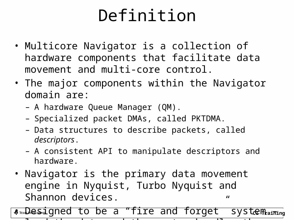
• Multicore Navigator is a collection of hardware components that facilitate data movement and multi-core control.
• The major components within the Navigator domain are:– A hardware Queue Manager (QM).– Specialized packet DMAs, called PKTDMA.– Data structures to describe packets, called descriptors.– A consistent API to manipulate descriptors and hardware.
• Navigator is the primary data movement engine in Nyquist, Turbo Nyquist and Shannon devices.
• Designed to be a “fire and forget” system – load the data and the system handles the rest, without CPU intervention.

CI Training
Navigator Architecture
L2 or DDR
QueueManager
Hardware Block
que pend
PKTDMA
Tx Streaming I/FRx Streaming I/F
Tx Scheduling I/F(AIF2 only)
Tx Scheduling Control
Tx Channel Ctrl / Fifos
Rx Channel Ctrl / Fifos
Tx CoreRx Core
QMSS
Config RAM
Link RAM
Descriptor RAMs
Register I/F
Config RAM
Register I/F
PKTDMA Control
Buffer Memory
Que Man register I/F
Input(ingress)
Output(egress)
VBUS
Host(App SW)
Rx Coh Unit
PKTDMA(internal)
Timer
PKTDMA register I/F
Que Interrupts
APDSP(Accum)
APDSP(Monitor)
que pend
Accumulator command I/F
Que Interrupts
Timer
Accumulation Memory
Tx DMA Scheduler
Link RAM(internal)
Interrupt Distributor

CI Training
Navigator Architecture: PKTDMA
L2 or DDR
QueueManager
Hardware Block
que pend
PKTDMA
Tx Streaming I/FRx Streaming I/F
Tx Scheduling I/F(AIF2 only)
Tx Scheduling Control
Tx Channel Ctrl / Fifos
Rx Channel Ctrl / Fifos
Tx CoreRx Core
QMSS
Config RAM
Link RAM
Descriptor RAMs
Register I/F
Config RAM
Register I/F
PKTDMA Control
Buffer Memory
Que Man register I/F
Input(ingress)
Output(egress)
VBUS
Host(App SW)
Rx Coh Unit
PKTDMA(internal)
Timer
PKTDMA register I/F
Que Interrupts
APDSP(Accum)
APDSP(Monitor)
que pend
Accumulator command I/F
Que Interrupts
Timer
Accumulation Memory
Tx DMA Scheduler
Link RAM(internal)
Interrupt Distributor

CI Training
Navigator Architecture: QMSS
L2 or DDR
QueueManager
Hardware Block
que pend
PKTDMA
Tx Streaming I/FRx Streaming I/F
Tx Scheduling I/F(AIF2 only)
Tx Scheduling Control
Tx Channel Ctrl / Fifos
Rx Channel Ctrl / Fifos
Tx CoreRx Core
QMSS
Config RAM
Link RAM
Descriptor RAMs
Register I/F
Config RAM
Register I/F
PKTDMA Control
Buffer Memory
Que Man register I/F
Input(ingress)
Output(egress)
VBUS
Host(App SW)
Rx Coh Unit
PKTDMA(internal)
Timer
PKTDMA register I/F
Que Interrupts
APDSP(Accum)
APDSP(Monitor)
que pend
Accumulator command I/F
Que Interrupts
Timer
Accumulation Memory
Tx DMA Scheduler
Link RAM(internal)
Interrupt Distributor

CI Training
Navigator Architecture: Host
L2 or DDR
QueueManager
Hardware Block
que pend
PKTDMA
Tx Streaming I/FRx Streaming I/F
Tx Scheduling I/F(AIF2 only)
Tx Scheduling Control
Tx Channel Ctrl / Fifos
Rx Channel Ctrl / Fifos
Tx CoreRx Core
QMSS
Config RAM
Link RAM
Descriptor RAMs
Register I/F
Config RAM
Register I/F
PKTDMA Control
Buffer Memory
Que Man register I/F
Input(ingress)
Output(egress)
VBUS
Host(App SW)
Rx Coh Unit
PKTDMA(internal)
Timer
PKTDMA register I/F
Que Interrupts
APDSP(Accum)
APDSP(Monitor)
que pend
Accumulator command I/F
Que Interrupts
Timer
Accumulation Memory
Tx DMA Scheduler
Link RAM(internal)
Interrupt Distributor

CI Training
Queue Manager Subsystem (QMSS)• Features:
– 8192 total hardware queues, some dedicated to qpend signals.• HW signals route to Tx DMA channels and chip level CPINTC.
– 20 Memory regions for descriptor storage (LL2, MSMC, DDR)– 2 Linking RAMs for queue linking/management
• Up to 16K descriptors can be handled by internal Link RAM.• Second Link RAM can be placed in L2 or DDR.
– Up to 512K descriptors supported in total.• Major hardware components:
– Queue Manager– PKTDMA (Infrastructure DMA)– 2 PDSPs (Packed Data Structure Processors) for:
• Descriptor Accumulation / Queue Monitoring• Load Balancing and Traffic Shaping
– Interrupt Distributor (INTD) module

CI Training
Queue Mapping• This table shows the mapping of queue number to functionality.• Queues associated with queue pend signals should not be used for general use, such as free
descriptor queues (FDQs). Others can be used for any purpose.
Queue Range Count Hardware Type
Purpose
0 to 511 512 pdsp/firmware Low Priority Accumulation queues
512 to 639 128 queue pend AIF2 Tx queues
640 to 651 12 queue pend PA Tx queues (PA PKTDMA uses the first 9 only)
652 to 671 20 queue pend CPintC0/intC1 auto-notification queues
672 to 687 16 queue pend SRIO Tx queues
688 to 695 8 queue pend FFTC_A and FFTC_B Tx queues (688..691 for FFTC_A)
696 to 703 8 General purpose
704 to 735 32 pdsp/firmware High Priority Accumulation queues
736 to 799 64 Starvation counter queues
800 to 831 32 queue pend QMSS Tx queues
832 to 863 32 Queues for traffic shaping (supported by specific firmware)
864 to 895 32 queue pend vUSR queues for external chip connections
896 to 8191 7296 General Purpose
CI Training
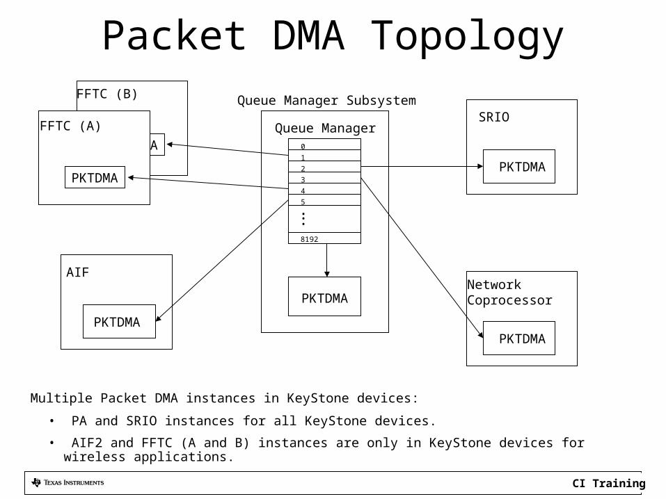
Packet DMA Topology
Multiple Packet DMA instances in KeyStone devices:
• PA and SRIO instances for all KeyStone devices.
• AIF2 and FFTC (A and B) instances are only in KeyStone devices for wireless applications.
PKTDMA
PKTDMA
PKTDMA
PKTDMA
PKTDMA
PKTDMA
Queue ManagerSRIO
Network Coprocessor
FFTC (A)
AIF
8192
5
4
3
2
1
0
.
..
Queue Manager SubsystemFFTC (B)

CI Training
Packet DMA (PKTDMA) Features• Independent Rx and Tx cores:
– Tx Core:• Tx channel triggering via hardware qpend signals from QM.• Tx core control is programmed via descriptors.• 4 level priority (round robin) Tx Scheduler
– Additional Tx Scheduler Interface for AIF2 (wireless applications only)– Rx Core:
• Rx channel triggering via Rx Streaming I/F.• Rx core control is programmed via an “Rx Flow” (more later)
• 2x128 bit symmetrical Streaming I/F for Tx output and Rx input– These are wired together for loopback in QMSS’ PKTDMA.– Connects to peripheral’s matching streaming I/F (Tx->Rx, Rx->Tx)
• Packet based, so neither Rx or Tx cores care about payload format.
CI Training
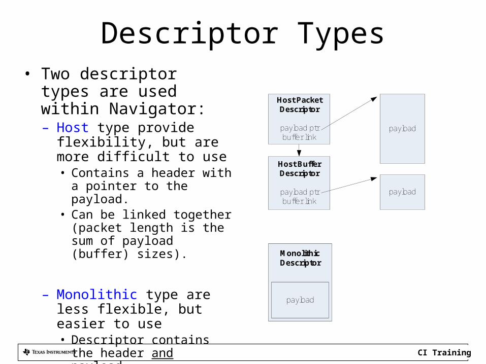
Descriptor Types• Two descriptor types are
used within Navigator:– Host type provide flexibility, but
are more difficult to use• Contains a header with a pointer
to the payload.• Can be linked together (packet
length is the sum of payload (buffer) sizes).
– Monolithic type are less flexible, but easier to use• Descriptor contains the header
and payload.• Cannot be linked together.• All payload buffers are equally
sized (per region).
Host Packet Descriptor
payload ptrbuffer link
payload
Host Buffer Descriptor
payload ptrbuffer link
payload
Monolithic Descriptor
payload
CI Training
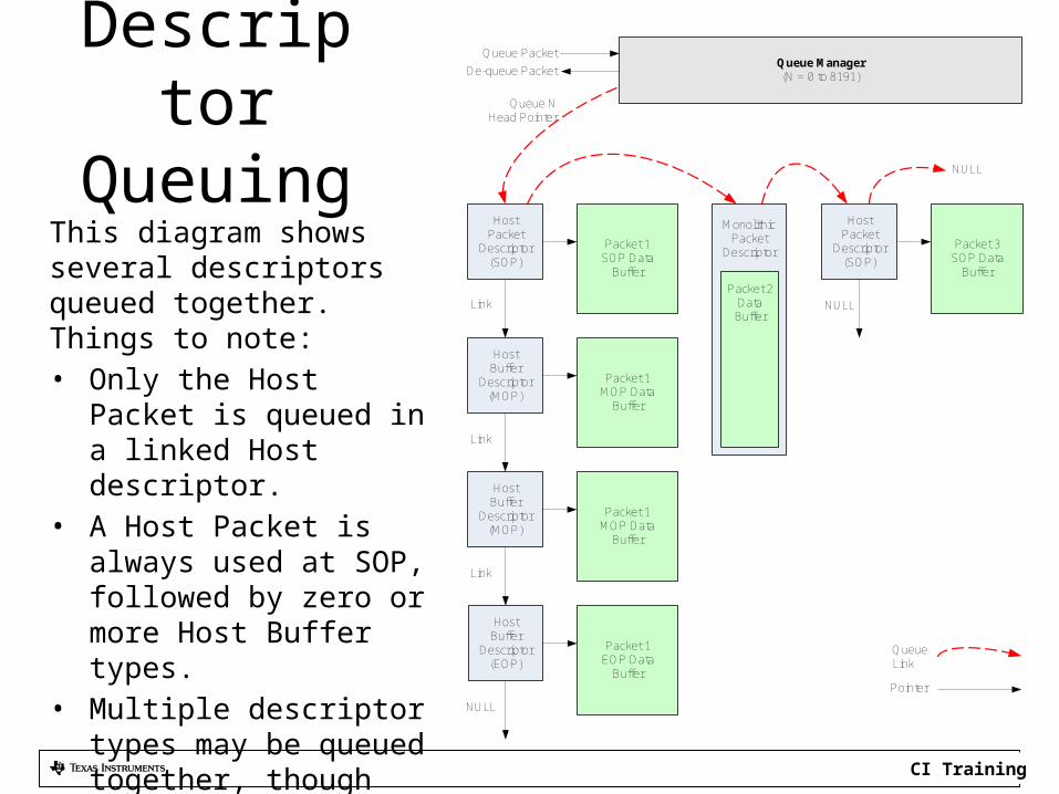
DescriptorQueuing
This diagram shows several descriptors queued together. Things to note:• Only the Host Packet is
queued in a linked Host descriptor.
• A Host Packet is always used at SOP, followed by zero or more Host Buffer types.
• Multiple descriptor types may be queued together, though not commonly done in practice.
Queue Manager(N = 0 to 8191)
Queue Packet
De-queue Packet
HostPacket
Descriptor(SOP)
HostBuffer
Descriptor(MOP)
HostBuffer
Descriptor(MOP)
Queue NHead Pointer
Link
Link
Link
Packet 1SOP Data
Buffer
Packet 1MOP Data
Buffer
Packet 1MOP Data
Buffer
HostPacket
Descriptor(SOP)
Packet 3SOP Data
Buffer
NULL
MonolithicPacket
Descriptor
Packet 2 DataBuffer
Pointer
Queue Link
HostBuffer
Descriptor(EOP)
NULL
Packet 1EOP Data
Buffer
NULL

CI Training
• What is Navigator?– Definition– Architecture– Queue Manager Sub-System (QMSS)– Packet DMA (PKTDMA)– Descriptors and Queuing
• What Can Navigator Do?– Data Movement– InterProcessor Communication– Job Management
What Can Navigator Do?

CI Training
Navigator Functionality• Three major areas:
– Data Movement• Peripheral input and output• Infrastructure, or core-to-core transfers• Chaining of transfers (output of PKTDMA A triggers
PKTDMA B)– Inter-Processor Communication (IPC)
• Task/Core synchronization• Task/Core notification
– Job Management• Resource Sharing• Load Balancing
CI Training
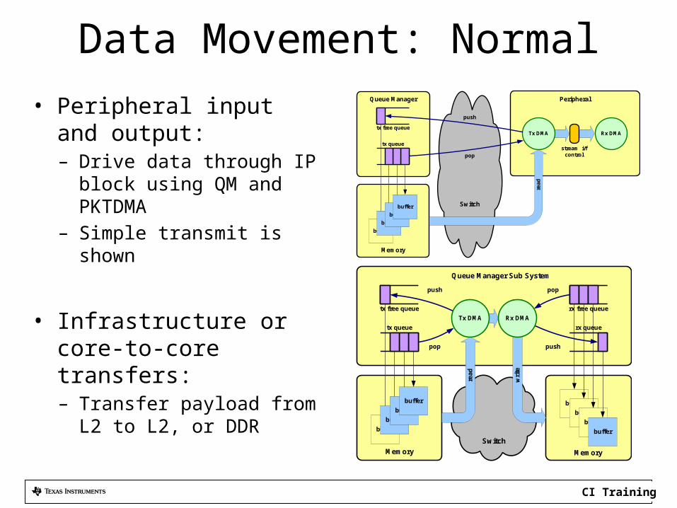
Data Movement: Normal• Peripheral input and output:
– Drive data through IP block using QM and PKTDMA
– Simple transmit is shown
• Infrastructure or core-to-core transfers:– Transfer payload from L2 to L2,
or DDRtx queue
buffer
buffer
buffer
buffer
Tx DMA
tx free queue
Queue Manager Sub System
Memory
Switch
buffer
buffer
buffer
buffer
rx free queue
rx queue
Rx DMA
rea
d
poppush
pop push
wri
te
Memory
tx queue
buffer
buffer
buffer
buffer
tx free queue
Queue Manager
Memory
Switch
push
pop
Peripheral
stream i/fcontrol
Rx DMA
read
Tx DMA

CI Training
Data Movement: Chaining• Chaining of IP transfers (output of PKTDMA 1 triggers PKTDMA 2).
Queue Manager
Switch
read
pop
push
consumer
producer
wri
te
Switch
pop
push
tx queue 1
buffer
buffer
buffer
buffer
tx free queue 1
Queue Manager
Memory
Switch
buffer
buffer
buffer
buffer
rx free queue 2
rx queue
push
pop
Memory
Peripheral 1
Peripheral 2
stream i/fcontrol
stream i/fcontrol
wri
te
Switch
Peripheral 1
stream i/fcontrol
read
Tx DMA
push
pop
Queue Manager
buffer
buffer
buffer
buffer
rx free queue 1
tx queue 2
Memory
pop
push
Rx DMA
pop
Switch
wri
te
tx free queue 2
pushread
Tx DMA Rx DMA• Chaining is accomplished by peripheral 1 pushing to a queue that is a Tx queue for peripheral 2.
CI Training
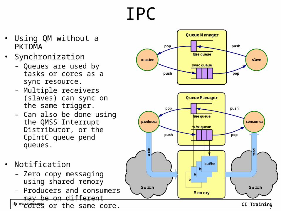
IPC• Using QM without a PKTDMA• Synchronization
– Queues are used by tasks or cores as a sync resource.
– Multiple receivers (slaves) can sync on the same trigger.
– Can also be done using the QMSS Interrupt Distributor, or the CpIntC queue pend queues.
• Notification– Zero copy messaging using shared
memory– Producers and consumers may be
on different cores or the same core.
– Notification can be interrupt or polling.
sync queue
Queue Manager
poppush
slavemaster
free queue
pop push
tx/rx queue
buffer
buffer
buffer
buffer
Queue Manager
MemorySwitch
read
poppush
consumerproducer
wri
te
Switch
free queue
pop push

CI Training
Job Management• Two main variations:
– Resource Sharing• Multiple job queues are scheduled for
a single shared resource.• A resource can be a peripheral
(e.g. FFTC) or a DSP task/core.
– Load Balancing• Single job queue is fanned out to
several resources.• The goal is to send a job to the least
busy core.
– Distributed (multi) schedulers are another variation.
CentralizedScheduler
CentralizedScheduler
CI Training
For More Information• For more information, refer to the to
Multicore Navigator User Guidehttp://www.ti.com/lit/SPRUGR9
• For questions regarding topics covered in this training, visit the support forums at the TI E2E Community website.


