K . .. i, . .,... . . a. . . .. . . .. . . . .., '. " ",,'-. ,." , .'.--,' ,'. W.._'._, ENGINEERING I INC. Structural Designers Consulting Engineers FULL SCALE TIEDOWN TEST Qualification Tests for VECTOR SYSTEMS SETS ON ASPHALT SURFACES PREPARED FOR Tiedown Engineering, Inc. 5901 Wheaton Drive Atlanta, GA 30336 (404) 344 - 0000 Phone (404) 349 - 0401 Fax October 11, 2000 BY John C. Doeden, P.E. K2 Engineering,rnc Lic.No 18546 , Georgia CONFIDENTIAL This report contains confidential and proprietary information that is intended for the sole use of the Clie'nt named above. This report may not be reproduced or further distributed without including cover and Table of Contents. / I. INTRODUCTION PAGE 1 II. PROCEDURE PAGE 1 III. RESULTS PAGE 4 IV. CONCLUSiONS PAGE 4 V. DATA - TEST #1, 2, & 3 PAGE 5 VI. PART DRAWINGS & SPECIFICATIONS: FIGURE1:59268 -VECTORASPHALT ADAPTER BRACKET PAGE6 FIGURE 2: 59116 - V-DRIVEROD PAGE7 FIGURE3:59277 - CONCRETEVECTORPAD PAGE 8 FIGURE4: 59276 -VECTORDIAGONAL CONNECTOR PAGE9 FIGURE5: 59282 -VECTORTENSION LINK PAGE 10 VII. PICTURES: FIGURE6:VECTORSTRAPENDCONNECTIONAT TENSIONLlNK PAGE 11 FIGURE7:DIGITALREAD-OUTFORTENSIONDIAGONAL PAGE 11 FIGURE8:DIAGONALSTRAPCONNECTION PAGE 12 VIII. INSTALLATION INSTRUCTIONS PAGE 13 & 14 TABLES: TABLE1-UNITTIEDOWNS&APPLIEDLOADS PAGE 3 TABLE2- BILLOFMATERIALS - VECTORSySTEM PAGE 3 'TABLE3-MAXIMUMUNITPIERHEIGHTS(TYPiCAL) PAGE 4 111 West Washington Street · Goshen,IN46526· Phone:219-534-5234. Fax:219-534-7196
Transcript
K.
..
i,.
.,....
.
a...
..
.
.
..
.
.. ..,'. " ",,'-. ,.",
.'.--,' ,'. W.._'._, ENGINEERING I INC.Structural Designers Consulting Engineers
FULL SCALE TIEDOWN TESTQualification Tests for
VECTOR SYSTEMSSETS ON ASPHALT SURFACES
PREPARED FOR
Tiedown Engineering, Inc.5901 Wheaton Drive
Atlanta, GA 30336(404) 344-0000 Phone(404) 349 - 0401 Fax
October 11, 2000
BYJohn C. Doeden, P.E.K2 Engineering,rncLic.No 18546 , Georgia
CONFIDENTIALThis report contains confidential and proprietary informationthat is intended for the sole use of the Clie'nt named above.This report may not be reproduced or further distributed withoutincluding cover and Table of Contents. /
I. INTRODUCTION PAGE 1II. PROCEDURE PAGE 1III. RESULTS PAGE 4
IV. CONCLUSiONS PAGE 4
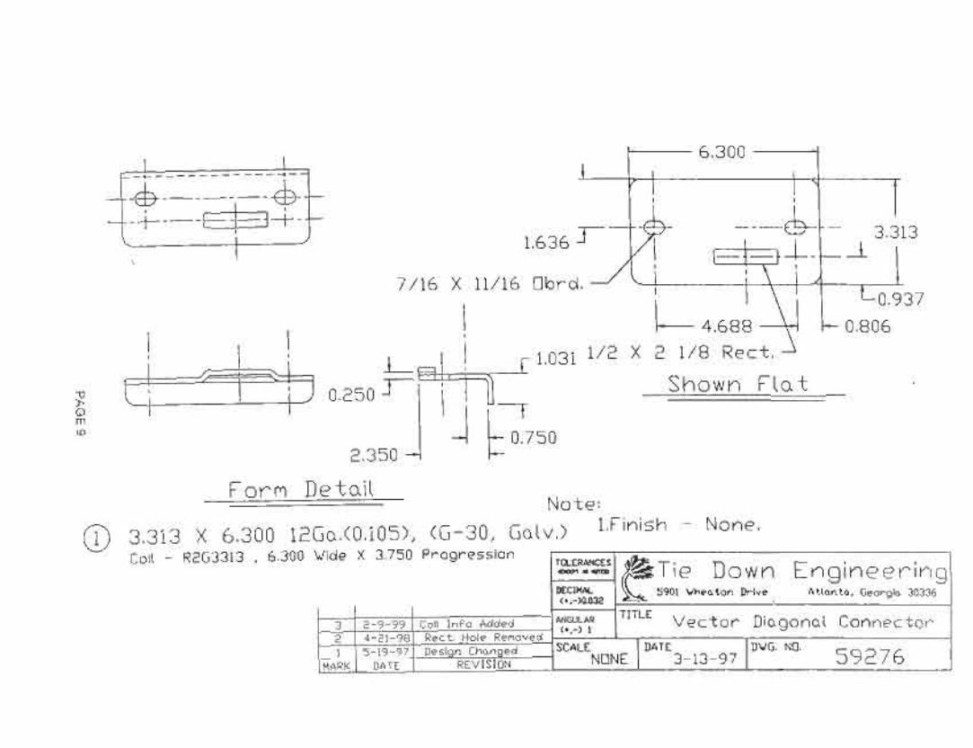
V. DATA - TEST #1, 2, & 3 PAGE 5VI. PART DRAWINGS & SPECIFICATIONS:FIGURE1:59268-VECTORASPHALTADAPTERBRACKET PAGE6FIGURE 2: 59116 - V-DRIVEROD PAGE7FIGURE3:59277-CONCRETEVECTORPAD PAGE 8FIGURE4: 59276-VECTORDIAGONALCONNECTOR PAGE9FIGURE5: 59282-VECTORTENSIONLINK PAGE 10
111 West Washington Street · Goshen,IN46526· Phone:219-534-5234. Fax:219-534-7196
K. .S'
'. -,,' .'"
.','~..
PAGE 1
ENGINEERING. INC.00-MH22-TDE
S t rUe t~,T .s' IDe s j 9 n e r s · C I) n J: u J tin g E n g'l n 9' Ii! I' 5
10/11/00
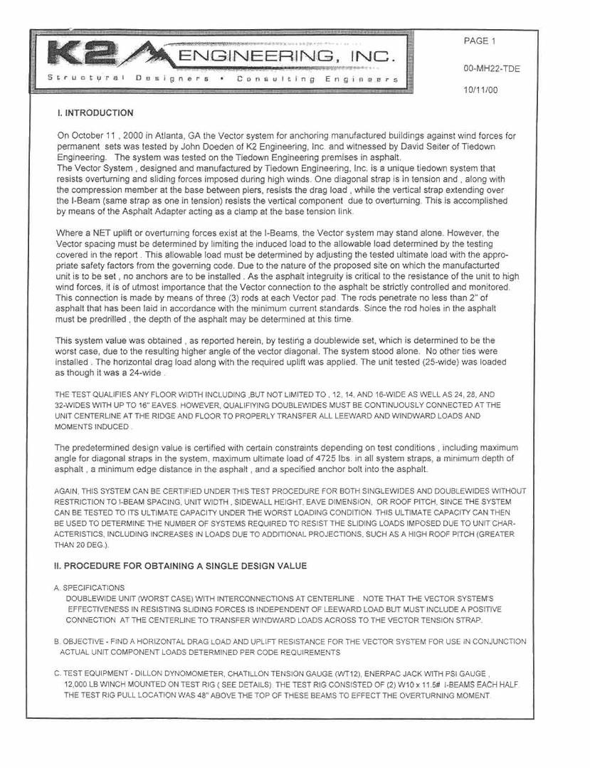
I. INTRODUCTION
On October 11 , 2000 in Atlanta, GA the Vector system for anchoring manufactured buildings against wind forces forpermanent sets was tested by John Doeden of K2 Engineering, Inc. and witnessed by David Seiter of TiedownEngineering. The system was tested on the Tiedown Engineering premises in asphalt.The Vector System, designed and manufactured by Tiedown Engineering, Inc. is a unique tiedown system thatresists overturning and sliding forces imposed during high winds. One diagonal strap is in tension and , along withthe compression member at the base between piers, resists the drag load, while the vertical strap extending overthe I-Beam (same strap as one in tension) resists the vertical component due to overturning. This is accomplishedby means of the Asphalt Adapter acting as a clamp at the base tension link.
Where a NET upliftor overturning forces exist at the I-Beams, the Vector system may stand alone. However, theVector spacing must be determined by limitingthe induced load to the allowable load determined by the testingcovered in the report. This allowable load must be determined by adjusting the tested ultimate load with the appro-priate safety factors from the governing code. Due to the nature of the proposed site on which the manufacturtedunit is to be set, no anchors are to be installed . As the asphalt integruity is critical to the resistance of the unit to highwind forces, it is of utmost importance that the Vector connection to the asphalt be strictly controlled and monitored.This connection is made by means of three (3) rods at each Vector pad. The rods penetrate no less than 2" ofasphalt that has been laid in accordance with the minimum current standards. Since the rod holes in the asphaltmustbe predrilled, the depthof the asphaltmaybedeterminedat this time.
This system value was obtained , as reported herein, by testing a doublewide set, which is determined to be theworst case, due to the resulting higher angle of the vector diagonal. The system stood alone. No other ties wereinstalled. The horizontal drag load along with the required uplift was applied. The unit tested (25-wide) was loadedas though it was a 24-wide .
THE TEST QUALIFIESANY FLOOR WIDTH INCLUDING ,BUTNOT LIMITEDTO, 12, 14,AND 16-WIDE AS WELL AS 24,28, AND32-WIDES WITH UP TO 16" EAVES. HOWEVER, QUALlFIYING DOUBLEWIDES MUST BE CONTINUOUSLY CONNECTEDAT THEUNIT CENTERLINE AT THE RIDGEAND FLOOR TO PROPERLYTRANSFERALL LEEWARD AND WINDWARD LOADS ANDMOMENTS INDUCED.
The predetermined design value is certified with certain constraints depending on test conditions, including maximumangle for diagonal straps in the system, maximum ultimate load of 4725 Ibs. in all system straps, a minimum depth ofasphalt, a minimum edge distance in the asphalt, and a specified anchor bolt into the asphalt.
AGAIN, THIS SYSTEMCAN BE CERTIFIEDUNDER THIS TEST PROCEDURE FOR BOTH SINGLEWIDES AND DOUBLEWIDESWITHOUTRESTRICTIONTO I-BEAM SPACING, UNIT WIDTH, SIDEWALL HEIGHT, EAVE DIMENSION, OR ROOF PITCH, SINCETHE SYSTEMCAN BE TESTED TO ITS ULTIMATE CAPACITY UNDER THE WORST LOADINGCONDITION. THIS ULTIMATE CAPACITY CAN THENBE USED TO DETERMINETHE NUMBEROF SYSTEMS REQUIREDTO RESIST THE SLIDING LOADS IMPOSED DUE TO UNIT CHAR-
ACTERISTICS, INCLUDING INCREASES IN LOADS DUE TO ADDITIONAL PROJECTIONS, SUCH AS A HIGH ROOF PITCH (GREATERTHAN 20 DEG.).
II. PROCEDURE FOR OBTAINING A SINGLE DESIGN VALUE
A. SPECIFICATIONS
DOUBLEWIDE UNIT (WORST CASE)WITH INTERCONNECTIONSAT CENTERLINE. NOTE THAT THE VECTOR SYSTEM'SEFFECTIVENESSIN RESISTING SLIDING FORCES IS INDEPENDENTOF LEEWARD LOAD BUT MUST INCLUDEA POSITIVE
CONNECTION AT THE CENTERLINE TO TRANSFERWINDWARD LOADS ACROSS TO THE VECTOR TENSION STRAP.
B. OBJECTIVE - FIND A HORIZONTAL DRAG LOAD AND UPLIFT RESISTANCE FOR THE VECTOR SYSTEM FOR USE IN CONJUNCTIONACTUAL UNITCOMPONENT LOADS DETERMINED PER CODE REQUIREMENTS,
C. TEST EQUIPMENT- DILLON DYNOMOMETER,CHATILLONTENSION GAUGE (WT12), ENERPAC JACK WITH PSI GAUGE,12,000 LB WINCH MOUNTED ON TEST RIG (SEE DETAILS).THE TEST RIG CONSISTED OF (2) W10 x 11.5# I-BEAMS EACHHALF.THE TEST RIG PULL LOCATION WAS 48" ABOVE THE TOP OF THESE BEAMS TO EFFECT THE OVERTURNING MOMENT.
Ie "...
'
.
,,'ij >, .", '"
.
. . 0>. '. ,
. ... .' "", ~'..' . '--' .~, - . 'i;A'"
PAGE 2
ENGINEERING. INC. 00-MH22- TOE
Struct\lrtlf Doslgners10/11/00
D. TESTING
The protocol for the Vector System, manufactured by Tiedown Engineering, Inc. , for ALLwind zones was performedin accordance with the Standard Building Code and the CABO 1 &2 Family Dwelling Code as required for anchoragetesting.As this is a uniquesystem that depends on the geometryof the manufacturedunitfor itseffectiveness, it wastested on an steel frame simulating an actual doublewide unit. Loads obtained and specified below for upliftanddrag are consistent with the proportion of each in relation to each other after accounting for the dead load contribution.Actual unit dead load is assumed to be 18 PSF minumum.
There was one Vector System anchored into 1-1/2" to 2" deep asphalt according to the installation instructionsprovided by Tiedown Engineering. The tension side strap had a strain gauge installed (in-line)to monitor strapload (pounds) in each Vector System. The horizontal movement of each system was read from the system padfarthest away from the pull with a tape measure and a stationary block. The maximum horizontal movement allowedat the system pad is 3". The instructions are to include the requirement to predrill holes in the asphalt no more than 1/8"less than the rod diameter after the Vector system is "in-place". Then the rods may be driven through the asphalt.
The drag load was induced by means of pulleys and steel cables attached to a winch on the test rig, which wasanchored to a tree. A dynamometer was installed (in-line) at the winch hook to monitor incremental loadings.The drag load was determined for a 102" vertical projection, including the floor (see Table 1).
The protocol states that the ultimate load is at the point where the system moves 3" or the load in the system tensionstrap is 4725 Ibs (whichever occurs first). However, if this point is reached before the fulluplift is obtained or the pullstops prematurely due to safety reasons, the uplift must conti~ue to be applied until fullultimate loads are achieved( per Table 1).
The uplift loads were applied at the outside I-Beams by means of heavy duty hydraulic jacks, two each beam.The location of each jack was approximately equidistant from the vertical tie each side to obtain load symmetry.The jacks were allowed to move freely in a lateral direction by means of base supports containing rollers.
The load resulting from the overturning moment was induced by additional uplift at the windward I-Beam (farthestfrom the tree). See the Table for loads at each beam. The vertical tiedown anchors under the highest tension load(windward wall side) were monitored for horizontal movement by means of a stake driven into the ground and atape measure. This movement is not required, but was requested by Tiedown Engineering for comparison purposes.
In addition, once the vertical ties begin seeing a load due to the applied force, the safety factor of 1.5 must be appliedto achieve the ultimate load. In an ideal set-up with the vertical ties taut (Le. tensioned properly), this will occurimmediatly after zero load is applied at the jacks. This implies that the reactions determined for the geometry arebe multiplied by 1.5 (see Table 1).
THE TEST RIG WAS JACKED AT FOUR POINTSTO DETERMINE ITS DEAD LOAD.TO OBTAIN THE TRUE NET UPLIFT LOAD THISLOAD MUST BE ADDED TO THE NET UPLIFT LOAD DETERMINED FOR THE APPLICABLE WIND ZONE.
DOUBLEWIDES: THE WORST CASE WIDTH (36-WIDE WITH A 12" EAVE- 35 FT. TOTAL WIDTH) WAS SIMULATEDFOR ACTUALLOADING, EVEN THOUGH A 24-WIDE WAS AVAILABLE FOR TESTING. THE TWO HALVES WERE CONNECTEDTOGETHER AS
REQUIRED BY UNIT DESIGN. THE UNITWAS JACKED OFF ITS PIERS (BEFOREANY ANCHORS WERE INSTALLED)ALONG THEOUTSIDE BEAMS ONLY FOR 2 PRELIMINARYOBJECTIVES:1. TO DETERMINETHE DEAD LOAD OF THE UNIT AND
2. TO VERIFY THAT THE TWO HALVESWOULD ACT (AS ASSUMED)AS A SINGLEWIDE AFTER INTERCONNECTIONSWERE MADE.SINGLEWIDES: THE WORST CASE WIDTH ( 12-WIDE WITH NO EAVE) WAS TO BE SIMULATED FOR ACTUAL LOADING, EVENTHOUGH A 14-WIDE IS AVAILABLE FOR TESTING. HOWEVER,THE I-BEAM SPACING ON THE ACTUAL UNITWAS NARROWER THAN75.5" AND HENCE RESULTED IN A MORE CONSERVATIVE TEST. TWO CHARACTERISTICS VALIDATING THIS STATEMENTARE THETESTED UNITS INABLILITYTO "DIG IN" AND THE MORE SEVERE ANGLE OF THE STRAP.ALSO, THE COLUMN ENGINEERINGANALYSIS OF A LONGER 94.5" 4x4 REQUIRED FOR A 99-/12" I-BEAM IS ACCEPTABLE IN THISRANGE OF COMPRESSION FORCES.
PAGE 3
, . ,.'ENGINEERING. INC~
00-MH22- TOES I.. f' 1.1 c t I,J r,al D es. j 9 n e r 5 . C I) n ti u I t I ng E n gin If e r ~
TABLE 1 -UNIT TIEDOWNS AND APPLIED LOADSDOUBLEWIDES
TEST No. - REFER TO DATA SHEETSUNIT WIDTH = 25'- 0"
I-BEAM SPACING =96" Tested (57" APART @ VECTOR)NUMBER OF VECTOR SYSTEMSNUMBEROF VERTICALTIESDEAD LOADOFTEST RIGHORIZONTALDRAGLOAD( TARGETULTIMATE)NET UPLIFT-TOTALWINDWARD( TARGETULTIMATE)NET UPLIFT-TOTAL LEEWARD ( ULTIMATE)ANGLE OF VECTOR DIAGONAL (FROM VERT.)LENGTH OF 4 x 4 COMPRESSION MEMBER
10/11/00
#111'- 10" Simulated75.5" c-c Simulated
1NIA
2,590 Ibs.6,310Ibs.2,250 Ibs.
o Ibs.60.64 Degrees
41 "
UPLIFT LOADS LISTED ARE AFTER DEAD LOAD IS REMOVED AS DETERMINED FROM WEIGHING THE ACTUAL TEST
UNIT. THEREFORE, ACTUAL LOAD APPLIED WAS GREATER BY THE WEIGHT OF THE RIG AT THE POINT OF LOAD.
Part and Descriptionl Name
Each Vector System consists of the following parts:TABLE 2 - BILL OF MATERIALS-
Quantity I Locationand Use
- Part No. 59277 - Concrete Vector Pad- Part No. 59282 - Vector Tension Link- Part No. 59276 - Vector Diagonal Connector
- Part No. 59268 -Vector Asphalt Adapter Bracket-3-1/2" U-bolt
- Stotted 5/8" tensioning bolts- 1-1/4" Standard Hurricane straps wI Radius Clip- Part No. 59116 - 18" V-Drive Rod
2
I
Pads form tied own connection & base for pier2 At base for Vertical strap attachment2 At base to combine Diagonal Strap and
compression member2
I
Resists loads when rods driven through into asphalt2 At base to secure Compression member to
Vector Diagonal Connector (Part No. 59276)2
I
At Tensioning Link (Part No. 59282)2 Each serves as a diagonal and vertical6 Secures Pad (59277) & Tension link (59282)
All tests were performed in fully cured asphalt only 2" thick, representing the worst case for anchor resistance.No torque probe readings were taken in the sub-base.Three (3) tests were performed with the drag load applied at 500 lb. increments for each dynamometer. The uplift incre-mental load required was determined by adding the unit dead load along each outside beam (total rig weight dividedby 2) to the design net uplift load and dividing this result by the design drag load. This fractional value was then multi-plied by 500 Ibs. for the increcremental uplift. Each jack would then receive this value divided by 2 at each load stage:
The worst condition is the narrowest singlewide and narrowest I-Beam spacing. For a 12-Wide this uplift due tooverturning is { [ 140/12 ( 13.5 - 18)- 2x35 ] x 75.5/2 + 1021\2/24( 22.5) } I 75.5 = 68 #/ft NET.
As an example; for Wind Zone the total uplift (load at jacks) should read 68#/ft x 22 ft.+ 2590/2 = 2790# , while thehorizontal load is 8.5 ft. x 22.5 PSF x 22 ft= 4210 #. This translates into an incremental uplift loading of 2790/4210 times500/2 Jacks = 165 Ibs. at each jack. This same load was not applied to the leeward side, since the net uplift load atthat location is less than zero (Le.[ (18-13.5) x 140/24 + 35] x 22> 2590/2).Note that the load of 22.5 and 13.5 PSF are derivatives of the HUD code and represent the adjusted loads includingthe 2/3 dead load resisting factor.
ALL SINGLEWIDES23'- 4" MIN.26'- 0" MIN.27'- 4" MIN.30'- 0" MIN.
4) Note that the Ultimate and Design limits are based on use of Tiedown Engineering's hurricane strap. With use ofany unknown strap (limit of 4725 # Ultimate load) , the Ultimate load for the system is 3150 Ibs.
5) The asphalt surfacing acts as the resistive medium and, as such, must be a Type 1/1course a minimum of 2" thickand must have been applied in accordance with the The Asphalt Institute's "Manual on Hot-Mix Asphaltic ConcretePavement". The asphalt must be free of cracks and edges within the footprint of the unit and must be predrilled withthe brackets in-place with a proper drill bit that is 1/16" to 1/8" less in diameter than that of the rod.
6) The number of systems required per unit length is based on the windward and leeward projection of the unit to dragforces in the appropriate Exposure in accordance with the requirements of the applicable code and spaced asevenly as practicable.
7) DOUBLEWIDES WITH THE VECTOR SYSTEM INSTALLED AND DESIGNED IN ACCORDANCE WITH THEPROVISIONS OF THIS REPORT MUST HAVE THE CENTERLINE JOINT CONNECTED (ONE HALF TO
THE OTHER) SO THAT THE ENTIRE UNIT PERFORMS AS A SINGLE STRUCTURE.
.~John C. Doeden, P.E.K2 Engineering, Inc.Test Engineer
Vector Dynamics Lateral FoundationSystem for Asphalt Applications
These instructions are an addendum to the standard Vector Dynamics instructions. Read and follow all
applicable instructions and guidelines in the Vector instructions and the instructions for the home, office,classroom or portable building being installed. Minimum depth of asphalt is 2 inches with a suitable base
material compacted under the asphalt. This system is designed for portable classrooms, offices or other
structures using I-beam frames.
1. The asphalt kit is used in combination with the Vector concrete kits 59006 and 59008. The expansion
bolts provided in these kits are not used. Assemble the asphalt bracket as shown in figure 1, using thecarriage bolts and hex nuts provided. The bolt heads will be on the underside (flat) of the Vector pad. The
Asphalt bracket will be positioned between the Vector pad and the tension bracket. Repeat for the second
pad.
2. Determine the location of the pier setswhere the Vector systemswill be located
3. place one of the assembled Vector pads on the asphalt where the pier will be located, centered under
the frame. The turned up end of the pad will face the inside of the building. place the second assembled
Vector pad under the opposite frame, parallel with the first pad.
4. Stack the concrete pier blocks on the Vector pads and wedge at this time. The upturned edge of the
Vector plates should be up against the side of the blocks.
5. Drill three 5/8" holes in the asphalt using the asphalt bracket as a guide. Holes will be at a 45 degree
angle under the pier. Using a sledge hammer or electric power demolition hammer, drive rods supplied
through the asphalt bracket and into the asphalt, leaving one inch of rod above the bracket. Repeat for thesecond pad (see figure 3).
6. Measure the distance between the two Vector system pads at the base where the Vector pad meets the
asphalt. Cut two ground treated 2x4's or a 4x4 this length and place between the piers as shown. place along u-bolt under the 2x4's and through the holes in the upturned edge of the Vector pad. Before securingwith the 3/8" nuts provided, place a 1/2"x 1" carriage bolt provided in the square hole in the upturned
edge of the Vector pad. The carriage bolt will be installed with the head of the bolt under the edge and thethreads showing above. This bolt will be used to attach the cross straps to the Vector base pads.
.. .. ..
. TIE DOWN ENGINEERING · 5901 Wheaton Drive · Atlanta GA, 30336 i,. rJ
7. Attacha strap with swivelstrap connectorto the 1/2" carriage bolt. Securewith 1/2" nut. Strap shouldbe of sufficientlengthto go over the opposite I-beamand down to the tension bracket with 12 to 15 inchesextra to wrap around the slottedbolt. (See figure2).
8. Insert a slotted bolt in the tension bracket. Cut strap so that there is 12 to 15 inches of strap available to
wrap around the slotted bolt. Insert the strap in the slotted bolt so that it is flush with the opposite side of thebolt. Tighten the bolt four to five turns until the strap is tight. Secure bolt with nut. Repeat for the secondpier/pad combination.
Figure :3
Figure 1
Figure 2 Figure4
TIE DOWN ENGINEERING · 5901 Wheaton Drive · Atlanta GA, 30336www.tiedown.com · (404) 344-0000. FAX (404) 349-0401
These instructions are an addendum to the standard VectorDynamics instructions. Readand followall applicable instructions and guidelines in the Vectorinstructions and homeinstallation manual. The Vector system for concrete pads applies to concrete footers,runners and slabs. Minimumsize of concrete per Vectorpier is 24"x24"x 4" or 18" round(min)x 10" deep. The bottom of footers must be below the frost line or a minimumof 4"below finished grade whichever is greater. Concrete must be sufficiently cured and setto accommodate an anchor bolt to its' full load resistance.
1. Determine locationof pier sets where the Vector systems willbe located.2. Place one Vectorconcrete pad (galv.metal) on the concrete where the pier willbe
located, centered under the I-beam of the home. Place the upturned edge towards thecenter of the home and directed to the opposite Vector pier. Do the same for the opposite
Vector pier.3. Measure the distance between the two Vector system pads at the base where the Vector
pad meets the concrete. Cut two ground treated 2x4's or Schedule 40 PVC pipe, or 1adjustable steel commpression member, part #59043 this length and place between thepiers as shown.
4. Place a long u-boltunder the 2x4's and through the holes of the Vector pad as shown.5. Place the concrete pier blocks on the Vector pad. Center the blocks under the frame. The
upturned edge end of the Vectorpads should be up against the inside of the pier blocks.6. Buildvectorpiersbutdo notwedgeat this time.7. Usinga concretedrill bit, drill two holeson eachside intothe concreteusingthe holesin
the Vectorpad as a guide.Drillthe 3/8"diameterholes3 inchesdeep.
8. Place an outside tension bracket on the Vector pad as shown in Illustration one. Line upthe holes in the bracket, Vector pad and concrete pad.
9. Put a washer and nut on one of the 3/8" x 3-3/4" wedge anchors. The nut should bescrewed on enough to have 1 or 2 threads showing on the top of the bolt. Place the wedgeend of the bolt into one of the holes, going through the outside tension bracket, metalVector pad and into the concrete.
10. Using a hammer, tap the wedge bolt into the hole. Maximum height for expansion boltabove concrete is 2".
11. Repeat for the other hole in the outside tension bracket and the two holes on the otherVector system pier set.
12. Place an inside tie bracket over the u-bolt so that the lip of the bracket is between theVector plate and concrete blocks. Place washers and nuts on each U-bolt. Do nottighten yet.
13. Attach a strap with hook or crimp seal to the inside tie bracket, with sufficient length to goover the opposite pier and down to the outside tension bracket, plus 12 inches forwrapping the slotted bolt. Repeat for the opposite side.
14. Tighten inside u-bolts at this time.15. Use the outside tension brackets to remove any space between the outside tension
brackets, concrete blocks and the inside edge of the Vector pad, by tapping the brackets
with a hammer. Wedge the pier set at this time.16. Using a 9/16" socket wrench, tighten all of the wedge/anchor bolts, securing the outside
tension bracket and Vector pad to the concrete.17. Using a slotted bolt in the outside tension brackets, insert strap through slotted bolt with
end of strap aligned with outside edge of bolt. Turn slotted bolt until straps are tight using
D\./G. NO.5 0 282MARK DATE REVISION" ACAD 6-10-96 7
K2f'
ENGINEERING, !NC.o .. ,- F
VII. PICTURES
./''I>
..
FIGURE 6: VECTOR STRAP END CONNECTION AT TENSION LINK
FIGURE 7: DIGITALREADOUT FOR TENSION DIAGONAL
PAGE 11
PAGE 11
00-MH22-TDE
10/11/00
KS ENGINEERING, INC...;;L ~ I.J C t 1.1 I"" a I 0 l son Frs
VII. PICTURES
FIGURE 8: DIAGONAL STRAP CONNECTION
PAGE12
PAGE 12
00-MH22- TOE
10/11/00
. -.----
Vector Dynamics Lateral FoundationSystem for Asphalt Applications
These instructions are an addendum to the standard Vector Dynamics instructions. Read and follow all
applicable instructions and guidelines in the Vector instructions and the instructions for the home, office,
classroom or portable building being installed. Minimum depth of asphalt is 2 inches with a suitable base
material compacted under the asphalt. This system is designed for portable classrooms, offices or otherstructures using I-beam frames.
1. The asphalt kit is used in combination with the Vector concrete kits 59006 and 59008. The expansion
bolts provided in these kits are not used. Assemble the asphalt bracket as shown in figure 1, using thecarriage bolts and hex nuts provided. The bolt heads will be on the underside (flat) of the Vector pad. The
Asphalt bracket will be positioned between the Vector pad and the tension bracket. Repeat for the secondpad.
2. Determine the location of the pier setswhere the Vector systemswill be located
3. place one of the assembled Vector pads on the asphalt where the pier will be located, centered under
the frame. The turned up end of the pad will face the inside of the building. place the second assembled
Vector pad under the opposite frame, parallel with the first pad.
4. Stack the concrete pier blocks on the Vector pads and wedge at this time. The upturned edge of the
Vector plates should be up against the side of the blocks.
5. Drill three 5/8" holes in the asphalt using the asphalt bracket as a guide. Holes will be at a 45 degree
angle under the pier. Using a sledge hammer or electric power demolition hammer, drive rods suppliedthrough the asphalt bracket and into the asphalt, leaving one inch of rod above the bracket. Repeat for the
second pad (see figure 3).
6. Measure the distance between the two Vector system pads at the base where the Vector pad meets theasphalt. Cut two ground treated 2x4's or a 4x4 this length and place between the piers as shown. place a
long u-bolt under the 2x4's and through the holes in the upturned edge of the Vector pad. Before securing
with the 3/8" nuts provided, place a 1/2"x1 " carriage bolt provided in the square hole in the upturnededge of the Vector pad. The carriage bolt will be installed with the head of the bolt under the edge and the
threads showing above. This bolt will be used to attach the cross straps to the Vector base pads.
7. Attach a strap with swivel strap connector to the 1/2" carriage bolt. Secure with 1/2" nut. Strap should
be of sufficient length to go over the opposite I-beam and down to the tension bracket with 12 to 15 inchesextra to wrap around the slotted bolt. (See figure 2).
8. Insert a slotted bolt in the tension bracket. Cut strap so that there is 12 to 15 inches of strap available towrap around the slotted bolt. Insert the strap in the slotted bolt so that it is flush with the opposite side of thebolt. Tighten the bolt four to five turns until the strap is tight. Secure bolt with nut. Repeat for the secondpier/pad combination.
Figure3
Figure1
Figure2 Figure4
TIE DOWN ENGINEERING · 5901 Wheaton Drive ·Atlanta GA, 30336www.tiedown.com · (404) 344-0000 · FAX (404) 349-0401