PEGAsys ™ Intelligent Suppression Control and Fire Alarm System Installation, Operation and Maintenance Manual July 2003 P/N 76-100016-001 R LISTED FM APPROVED UL Listing File No. S2422 Factory Mutual Approval J.I. No. OB2A6.AY
Transcript
PEGAsys™
Intelligent Suppression Controland Fire Alarm System
Intelligent Suppression Controland Fire Alarm System
Installation,Operation and
Maintenance Manual
July 2003P/N 76-100016-001
THIS PAGE INTENTIONALLY LEFT BLANK.
i
FOREWORD
TERMS AND ABBREVIATIONS
AC Alternating Current
ADA Americans with Disabilities Act
AH Ampre Hour
AI Addressable Contact Input Device
AO Addressable Relay Output Device
AST Alarm Simulation Test
ATM Annunciator Terminal Module
BIP Broadcast Indexed Protocol
BPM Beats Per Minute
CCM Central Control Module
CCP Central Control Panel
DC Direct Current
EDP Electronic Data Processing
EOC Event Output Control
ESD Electrostatic Discharge
FCP Fire Control Panel
GUI Graphical User Interface
HSSD High-Sensitivity Smoke Detector
HVAC Heating, Ventilating and Air Conditioning
I/O Input/Output
ID Identification
IRI Industrial Risk Insurers
LCD Liquid Crystal Display
LED Light Emitting Diode
ML Multi-Loop
NC Normally Closed
Note: This Manual Is To Be Used By Trained Distributors Only
This manual is intended to clearly and accurately reflect the PEGAsys Fire Alarm/Suppression Control System.This publication describes the operation, installation and maintenance of the PEGAsys Fire Alarm/SuppressionControl System, P/Ns 76-100000-501 for Single-Loop System and 76-100000-600 for Multi-Loop System.
NCCM Networkable Central Control Module
NIC Network Interface Card
NFPA National Fire Protection Agency
NO Normally Open
NR Not Registered
NYC New York City
P/N Part Number
PALM PEGAsys Addressable Loop Module
PAS Positive Alarm Sequence
PC Personal Computer
PCB Printed Circuit Board
PCS PEGAsys Configuration Software
PC Line Power/Communication Line (RX/TX Loop)
PS Power Supply
RCU Remote Control Unit
RDCM Remote Display Control Module
RDM Remote Display Module
RTC Real-Time Clock
RX/TX Receive Transmit
SL Single-Loop
SLC Signaling Line Circuit
SPDT Single Pole, Double Throw
UL Underwriter Laboratories
V Volts
Vac Voltage Alternating Current
Vdc Voltage Direct Current
ii
ACCEPTANCES, APPROVALS AND CERTIFICATIONS
PEGAsys Single-Loop System (P/N 76-100000-501)
• UL: Underwriters Laboratories Listing File Number S2422.
• CSFM: California State Fire Marshal Listing Number 7165-1076:146.
• NYC: City of New York Listing Number MEA 454-91-E Vol.III.
iii
Foreword ................................................................................................................................... iTerms and Abbreviations ........................................................................................................... iAppendices ................................................................................................................................ viiList of Illustrations ...................................................................................................................... viiiList of Tables ............................................................................................................................. xSafety Summary ........................................................................................................................ xi
4 Maintenance Procedure .......................................................................................................... 4-14-1 Introduction ................................................................................................................................ 4-14-2 Scheduled Maintenance ............................................................................................................ 4-14-3 Maintenance Procedures ........................................................................................................... 4-14-3.1 Lamp Test .................................................................................................................................. 4-14-3.2 Loop Device Test ....................................................................................................................... 4-14-3.3 Battery Test ................................................................................................................................ 4-24-3.4 Walk Test ................................................................................................................................... 4-24-3.4.1 Walk Testing Detectors .............................................................................................................. 4-24-3.4.2 Walk Test Procedure ................................................................................................................. 4-24-3.5 Alarm Simulation Test (AST) ..................................................................................................... 4-34-3.5.1 AST Procedure .......................................................................................................................... 4-34-4 Disarming and Rearming Release Circuits ................................................................................ 4-34-4.1 Disarming Release Circuits ....................................................................................................... 4-44-4.2 Arming Release Circuits ............................................................................................................ 4-44-5 Powering Down the System....................................................................................................... 4-44-5.1 Power-Down Procedure ............................................................................................................ 4-44-6 Powering Up the System ........................................................................................................... 4-44-6.1 Power-Up Procedure ................................................................................................................. 4-4
5 Troubleshooting and Corrective Maintenance ..................................................................... 5-15-1 Introduction ................................................................................................................................ 5-15-2 Standard Fault-Isolation Techniques .......................................................................................... 5-15-2.1 Visual Inspection ....................................................................................................................... 5-15-2.2 Power Checks ........................................................................................................................... 5-15-3 Troubleshooting ......................................................................................................................... 5-15-4 Removal and Replacement ....................................................................................................... 5-25-4.1 Required Tools ........................................................................................................................... 5-25-4.2 Central Control Module .............................................................................................................. 5-25-4.3 RX/TX Module ........................................................................................................................... 5-25-4.4 Field Devices ............................................................................................................................. 5-3
6 Parts List .................................................................................................................................. 6-16-1 Introduction ................................................................................................................................ 6-1
2-1 System Front Panel ................................................................................................................... 2-12-2 Menu Structure .......................................................................................................................... 2-52-3 Active Alarms Example .............................................................................................................. 2-72-4 Supervisory Example for Supervisory Mode Indication ............................................................. 2-112-5 Active Troubles and Pre-Alarms Example ................................................................................. 2-112-6 Output Module Address Scheme ............................................................................................... 2-132-7 RCU Registration Screen .......................................................................................................... 2-15
3-17 DH-2000 Air Duct Housing ........................................................................................................ 3-103-18 Loop Isolator, RX/TX Mount ...................................................................................................... 3-113-19 Loop Isolator, Stand-Alone......................................................................................................... 3-113-20 Loop Isolator, 6-inch Detector Base Mount ................................................................................ 3-113-21 PALM Interface Module for ORION XT HSSD ........................................................................... 3-113-22 Addressable AlarmLine Module ................................................................................................. 3-113-23 Addressable Signal/Sounder Module ........................................................................................ 3-12
5-1 Single Loop Installation .............................................................................................................. 5-25-2 Multi-Loop Installation ................................................................................................................ 5-2
7-1 CCP Installation Drawing ........................................................................................................... 7-17-2 Back Plate, Output Motherboard and Four Power Supplies ...................................................... 7-27-3 Back Plate, Eight Power Supplies ............................................................................................. 7-27-4 Back Plate, Two Output Motherboards ...................................................................................... 7-27-5 Installation for Multi-Loop .......................................................................................................... 7-37-6 Power Supply/Charger Wiring Diagram ..................................................................................... 7-47-7 Power Supply/Charger Wiring Diagram for Expansion Enclosure ............................................ 7-57-8 RS-485 Connection ................................................................................................................... 7-57-9 Battery Enclosure ...................................................................................................................... 7-67-10 Conduit to CCP.......................................................................................................................... 7-67-11 Shielded Wire to CCP ............................................................................................................... 7-77-12 Style 4, RX/TX PC Line Connections......................................................................................... 7-77-13 Style 6, RX/TX PC Line Connections......................................................................................... 7-77-14 Style 6, RX/TX PC Line Connections with Loop Isolators .......................................................... 7-87-15 Style 7, RX/TX PC Line Connection .......................................................................................... 7-87-16 CCM Printer Port ....................................................................................................................... 7-10
x
LIST OF TABLES
TABLE TITLE PAGE
1-1 System Specifications................................................................................................................ 1-8
2-1 Controls and Indicators .............................................................................................................. 2-2 2-2 Isolate Menu Function ............................................................................................................... 2-8 2-3 List Menu Function .................................................................................................................... 2-8 2-4 Set Menu Function .................................................................................................................... 2-9 2-5 Test Menu Functions ................................................................................................................. 2-10
6-1 PEGAsys System Parts List ...................................................................................................... 6-1
7-1 RX/TX Configuration Selection .................................................................................................. 7-3 7-2 Aux. Power Supply Module Connections to Main Power Supply/Charger Assembly ................. 7-5
xi
SAFETY SUMMARY
Note: Installation Precautions– Adherence to the following will aid in problem-free installation with long-term reliability.
WARNING!
Several different sources of power can be connected to this fire alarm control panel. Disconnect allsources of power before servicing. Control unit and associated equipment may be damaged by removingand/or inserting cards, modules, or interconnecting cables while the unit is energized. Do not attempt toinstall, service, or operate this unit until this manual is read and understood.
CAUTION!
System Reacceptance Test after Software Changes: To ensure proper system operation, this productmust be tested in accordance with NFPA-72 (2002) Chapter 10 after any programming operation or changein site-specific software. Reacceptance testing is required after any change, addition or deletion of systemcomponents, or after any modification, repair or adjustment to system hardware or wiring.
All components, circuits, system operations, or software functions known to be affected by a changemust be 100% tested. In addition, to ensure that other operations are not inadvertently affected, at least10% of initiating devices that are not directly affected by the change, up to a maximum of 50 devices,must also be tested and proper system operation verified.
This system meets NFPA requirements for operation at 0° to 49° C and at a relative humidity of 85% (non-condensing) @ 30°C. However, the useful life of the system’s standby batteries and the electroniccomponents may be adversely affected by extreme temperature and humidity variations. Therefore, it isrecommended that this system and its peripherals be installed in an environment with a nominal roomtemperature of 60° to 80°F.
Like all solid state electronic devices, this system may operate erratically or can be damaged whensubjected to lightning induced transients. Although no system is completely immune from lightningtransients and interference, proper grounding will reduce susceptibility. The use of overhead or outsideaerial wiring is not recommended due to the increased susceptibility to nearby lightning strikes. Consultwith the Applications Engineering Department if any problems are anticipated or encountered.
Disconnect AC power and batteries prior to removing or inserting circuit boards. Failure to do so candamage circuits.
Remove all electronic assemblies prior to any drilling, filing, reaming, or punching of the enclosure.When possible, make all cable entries from the sides. Before making modifications, verify that they willnot interfere with battery and printed circuit board location.
Do not over tighten screw terminals. Over tightening may damage threads, resulting in reduced terminalcontact pressure and difficulty with screw terminal removal.
This system contains static-sensitive components. Always ground yourself with a proper wrist strapbefore handling any circuits so that static charges are removed from the body. Use static suppressivepackaging to protect electronic assemblies removed from the control unit.
Follow the instructions in the installation, operating, and programming manuals. These instructions mustbe followed to avoid damage to the control panel and associated equipment. System operation andreliability depend upon proper installation.
FIRE ALARM SYSTEM LIMITATIONS
Note: While installing a fire alarm system may make lower insurance rates possible, it is not a substitute for fire insur-ance!
An automatic fire alarm system—typically made up of smoke detectors, heat detectors, manual pull stations, audiblewarning devices, and a fire alarm control unit with remote notification capability—can provide early warning of a develop-ing fire. Such a system, however, does not assure protection against property damage or loss of life resulting from a fire.
xii
Any fire alarm system may fail for a variety of reasons:
Smoke detectors may not sense fire where smoke cannot reach the detectors such as in chimneys, in walls, or roofs, oron the other side of closed doors. Smoke detectors also may not sense a fire on another level or floor of a building. Asecond floor detector, for example, may not sense a first floor or basement fire. Furthermore, all types of smoke detec-tors—both ionization and photoelectric types—have sensing limitations. No type of smoke detector can sense every kindof fire caused by carelessness and safety hazards like smoking in bed, violent explosions, escaping gas, improper stor-age of flammable materials, overloaded electrical circuits, children playing with matches or arson.
Audible warning devices such as bells may not alert people if these devices are located on the other side of closed orpartly open doors or are located on another floor of a building.
A fire alarm system will not operate without electrical power. If AC power fails, the system will operate from standbybatteries only for a specified time.
Rate-of-rise heat detectors may be subject to reduced sensitivity over time. For this reason, the rate-of-rise feature ofeach detector should be tested at least once per year by a qualified fire protection specialist.
Auxiliary equipment used in the system may not be technically compatible with the control panel. It is essential to use onlyequipment listed for service with your control panel.
Telephone lines needed to transmit alarm signals from a premise to a central monitoring station may be out of service ortemporarily disabled.
The most common cause of fire alarm malfunctions, however, is inadequate maintenance. All devices and system wiringshould be tested and maintained by professional fire alarm installers following written procedures supplied with eachdevice. System inspection and testing should be scheduled monthly or as required by national and/or local fire codes.Adequate written records of all inspections should be kept.
GENERAL SAFETY NOTICES
Note: The following must be observed to maintain personnel safety.
The following general safety notices supplement specific warnings and cautions appearing in the manual. The safetyprecautions in this section must be understood and applied during operation and maintenance. This manual is to be usedby trained distributors/technicians. The entire manual should be read and fully understood prior to installation.
TEST EQUIPMENT
Make certain test equipment is in good operating condition. Do not touch live equipment or personnel working on liveequipment while holding a test meter. Some types of measuring devices should not be grounded; these devices shouldnot be held when taking measurements.
FIRST AID
Any injury, no matter how slight, should never go unattended. Always obtain first aid or medical attention immediately.
GENERAL PRECAUTIONS
The following general safety precautions are to be observed at all times:
1. All electrical components associated with equipment shall be installed and grounded in accordance with NEC, NFPAand local regulatory requirements.
2. Special precautionary measures are essential to prevent applying power to equipment at any time maintenance workis in progress.
3. Before working on electrical equipment, use a voltmeter to ensure that the system is not energized.
4. When working near electricity, do not use metal rulers, flashlights, metallic pencils or any other objects having ex-posed conductive material.
5. When connecting a meter to terminals for measurement, use voltage range higher than the expected voltage.
THIS PAGE INTENTIONALLY LEFT BLANK.
January 2002
PEGAsys™
1-0 76-100016-001
Fig
ure
1-1.
PE
GA
sys
Sys
tem
, Ove
rall
Dia
gram
Addre
ssable
Suppre
ssio
nS
yste
mA
bort
Devic
e
PU
SH
/H
OL
D
SU
PP
RE
SS
ION
SY
ST
EM
AB
OR
T
PU
SH
PU
LL
R
FIR
EA
LA
RM
FIR
EA
LA
RM
RS
-48
5
Ala
rmN
otifica
tio
nA
pp
lian
ce
s
1-1 July 2003
PEGAsys™
76-100016-001
CHAPTER 1GENERAL INFORMATION
1-1 INTRODUCTION
This manual contains the operation, maintenance, trouble-shooting, parts listing and installation information neces-sary to support the PEGAsys™ Intelligent SuppressionControl and Fire Alarm System.
Note: This manual is to be used by trained distributorsonly. The entire manual should be read and fullyunderstood prior to installation. Refer to Figure 1-1 for the PEGAsys System overall diagram.
1-1.1 System Description
PEGAsys is a fire alarm/suppression control system whichcan be used for local, auxiliary, remote protective signal-ing and releasing device service. The system is a micro-processor based design for use with intelligent detectorsand loop devices.
The system utilizes distributed intelligent field devices.These devices are typically smoke detectors, contact in-put devices, relay outputs and signal output modules whichrepresent a single fire alarm initiation/indicating zone. Eachdevice contains its own data transceiver, micro controller,4K of memory and applicable algorithms which allows eachdevice to operate independently of the control system.These unique devices have the ability to analyze informa-tion, make decisions and store information within them-selves. They communicate with the PEGAsys system usingthe BIP protocol which utilizes a two-wire (Style 4), fourwire (Style 6) or isolated (Style 7) multiplex trunk. ThePEGAsys can support up to 255 device addresses per loop,with a maximum of eight (8) loops, for a total of 2,040 in-telligent device points per system.
The PEGAsys is capable of controlling a wide variety ofauxiliary devices, such as relays, audible/visual indicatingsignal devices and agent/sprinkler release systems. Thesystem also supports the use of serial printers which pro-vide hard copy of system status information.
There are three versions of the PEGAsys currently in ser-vice. These three versions are identified as:
• Pre-Network,
• Networkable, and
• Networkable and directly-integrable with ORION™XT High-Sensitivity Smoke Detectors (HSSDs).
Pre-networked systems have operating firmware in theCentral Control Module (CCM) that ranged from Version48.0 to Version 6X.X. All pre-networked systems must now
have Version 60.0, or higher, operating firmware. Pre-net-worked systems are not covered in this manual.
Networkable systems have a modified CCM that can ac-cept a Network Interface Card (NIC) for peer-to-peer con-trol unit operations, and can accommodate Remote DisplayModules (RDMs), Remote Display Control Modules(RDCMs) and ATM Series Driver Modules (ATM-L/R).Networkable systems have CCM Version 7X.X firmware.
Networkable systems that are directly-integrable withORION XT HSSDs have Version 8X.X CCM firmware.
1-1.2 System Components
The system is comprised of three major components, asshown in Figure 1-1: the Central Control Panel (CCP) whichcommunicates with the field devices and drives outputdevices such as alarm signals that communicate with cen-tral stations and various types of control equipment; a dis-play panel located on the CCP that provides system statusLEDs and Control Switches; and an 80-character LCD thatprovides alphanumeric display of system status informa-tion.
The single-loop PEGAsys Central Control Panel (P/N76-100000-501) consists of the Central Control Module(CCM) assembly, one receiver/transmitter (RX/TX) mod-ule and one power supply assembly. Optionally the sys-tem can add a motherboard assembly which allows for theinstallation of optional output modules. An auxiliary powersupply module can be added which increases the basesystem power supply capacity to 8.0 Amps at 24 Vdc.
In multi-loop form, the PEGAsys ML panel (P/N 76-100000-600) consists of a CCM, one (1) power-supply assembly,one (1) RX/TX module and one (1) multi-loop motherboardmounted in the enclosure. The unique multi-loopmotherboard provides the ability to connect up to eight (8)RX/TX modules to the system which allows for a full 2,040addressable points to be connected to the PEGAsys MLsystem.
Auxiliary enclosures are available to allow the system tobe expanded. The auxiliary enclosure has the same di-mensions as that of the main enclosure, with the absenceof the window in the door. There are optional backplanesthat install in the expansion enclosure. This allows the num-ber of output modules and system power supplies to beexpanded. To allow for maximum system flexibility and ex-pansion, enclosure(s) and backplane(s) can be added tothe system. See Appendix B for further system expansiondetails.
1-2July 2003 76-100016-001
PEGAsys™
1-2 COMPONENT DESCRIPTION
The following paragraphs give a brief description of eachcomponent used in the PEGAsys system. For functionaldescriptions of each component, see Chapter 3 of thismanual.
1-2.1 Central Control Module (CCM)
The CCM assembly is the heart of the system and is com-prised of two (2) printed circuit board (PCB) assemblies,the display module and the main processor module. TheCCM controls the operation and supervision of all the sys-tem modules and software within the PEGAsys system. Itreceives loop device data from the RX/TX module, pro-cesses the data based on pre-programmed instructionsand transmits output commands to the output modules,field devices and display module(s).
1-2.2 Display Module
The display module assembly, attached to the main pro-cessor PCB, provides the system with the operator inter-face for control switches, system status LEDs, systemtrouble/alarm buzzer, an 80-character (2 x 40) LCD dis-play and an integral numeric keypad. The keypad is usedfor entering the security password and navigating throughthe user menus. The system buzzer provides two (2) dis-tinctly different signaling patterns for audible warning ofsystem alarms and troubles.
PRE-ALARM
ALARM
AC POWER SYSTEM TROUBLE
SUPERVISORY
SILENCE
SYSTEMACKNOWLEDGE
SYSTEMRESET
SILENCE
SCROLL
SYSTEM STATUS DISPLAY
R
Display ResetSwitch
PLG2
JK1
JK2
PLG3
SW1
PLG2
JK3
PLG1
PRINT PORTDS1
0V
24
VDC
EARTH
FAULT
SUPPLY
FAULT
TB6
BUZZER
ProcessorPort
DisplayPort
PC Port
Display TroubleLED
24 Vdc fromPower Supply
Figure 1-2. Central Control Module (CCM)
PRE-ALARM
ALARM
AC POWER SYSTEM TROUBLE
SUPERVISORY
SILENCE
SYSTEMACKNOWLEDGE
SYSTEMRESET
SILENCE
SCROLL
SYSTEM STATUS DISPLAY
R
Figure 1-3. Display Module Assembly
1-2.3 Receiver/Transmitter Module (RX/TX)
The RX/TX functions as the hardware and software inter-face between the field devices and the CCM. The RX/TXreceives control requests from the CCM, and establishescommunications with the field devices. The RX/TX receivesstatus changes from the field devices and reports thesechanges to the CCM. The RX/TX, shown in Figure 1-4, iscapable of communicating with up to 255 intelligent de-vices and complies with the wiring requirements of NFPAStyle 4, 6 and 7 (with the use of the loop isolator devices).Style 4 initiation circuit wiring will permit “T” tapping orbranch circuitry.
1-2.4 Power Supply/Charger Assembly
The power supply/charger assembly (P/N 76-100009-010)is comprised of a PCB assembly and an AC/DC switchingpower supply unit. The switching power supply unit pro-vides 4 Amps of 24 Vdc from the 120/240 Vac input power.The PCB assembly is a microprocessor based unit whichprovides the system with:
• Battery charging and supervision
• AC power supervision
• 24 Vdc supervision
• Battery load test
• 24 Vdc ground fault detection (+/-)
• Auxiliary 24 Vdc outputs
Loop Isolatorfor Style 7
Figure 1-4. Receiver/Transmitter Module (RX/TX)
1-3 July 2003
PEGAsys™
76-100016-001
Figure 1-5. Power Supply/Charger Assembly
1-2.5 Basic Motherboard
The basic motherboard assembly (P/N 76-100007-001) isan assembly which can accept up to eight (8) output mod-ule circuit board assemblies. The motherboard is mountedto the back of the system enclosure and/or the auxiliaryenclosures. It distributes 24 Vdc power and bus communi-cations to the output modules. The bus communicationsare provided by an RJ-12 (flat phone cable) style connec-tion. The 24 Vdc is provided by the system power supplyvia a two-conductor wiring harness. The motherboardmounts to standoffs on the back of the main and expan-sion enclosures with screws which are provided.
R1 W1
J1 J2 J3 J4 J5 J6 J7 J8 TB1+24V
RET
TB2
485B
485A
SIG GND
COM ALM
COM TBL
J9
RS-485
Figure 1-6. Basic Motherboard
1-2.6 Multi-Loop Motherboard
The multi-loop motherboard assembly (P/N 76-100017-001) is an assembly which can accept up to eight (8)RX/TX modules and provide connections for up to seven(7) output module circuit board assemblies. The MLmotherboard is mounted to standoffs on the back of themain system enclosure. It distributes 24 Vdc power, CCM-RX/TX communications for up to eight (8) RX/TX mod-ules and bus communications to the output modules. Thebus communications are provided by an RJ-12 (flat phonecable) style connection. A single RJ-12 connection con-nects the ML motherboard to the CCM for RX/TX commu-nications. The 24 Vdc is provided by the system powersupply via a two-conductor wiring harness. The allowable
combinations of RX/TX and output modules that can beused with a Multi-Loop Motherboard are as follows:
)s(XT/XRfo.oN seludoMtuptuOfo.oN
2ro1 7–1
3 6–1
4 5–1
5 4–1
6 3–1
7 2–1
8 1
W1
J1 J3 J4 J5 J6 J7J2 TB9+24V
RET
TB10
485A
SIG GND
COM ALM
COM TBL
485B
JP1JP2JP3JP4JP5JP6JP7JP8
TB8 TB7 TB6 TB5 TB4 TB3 TB2 TB1
TB11
+24V
RET
JP10
RS-232
JP9RS-485
Figure 1-7. Multi-Loop Motherboard
1-2.7 Output Modules
The optional output modules allow the PEGAsys systemto interface with external auxiliary devices. These auxil-iary devices can be audible/visual signal devices, HVACsystems, elevator recall, power shut down, remote annun-ciators, agent/sprinkler release system and any other con-trol type output which may need to be interfaced to thesystem.
The output modules plug into the motherboard assemblylocated on the backplate of the system enclosure. Eachmodule occupies one slot in a motherboard assembly. Themodules and the CCM communicate over the RS-485based bus, which uses a six-conductor, phone-type cableto connect the CCM to the motherboard.
The PEGAsys single-loop panel has the ability to supporta maximum of sixteen (16) output modules, in any combi-nation. However, no more than eight (8) of any one type ofmodule can be used. The system is limited to one City-TieModule.
The PEGAsys multi-loop panel has the ability to support amaximum of twenty-three (23) output modules, in any com-bination in the system. However, no more than eight (8) ofany one type of module can be used, and the system islimited to one City-Tie Module.
The following paragraphs describe each available outputmodule in greater detail.
1-4July 2003 76-100016-001
PEGAsys™
1-2.7.1 SIGNAL OUTPUT MODULE
The PEGAsys panel has the capacity for a maximum ofeight (8) Alarm Sounder/Signal Output cards, thus provid-ing thirty-two (32) possible Class B, Style "Y" signal cir-cuits. Each Alarm Sounder/Signal Output card is equippedwith supervised 24 Vdc outputs which can operate as ClassB, Style “Y” or Class A, Style “Z” indicating circuits (seeFigure 1-8).
76-1
00003-0
01
Figure 1-8. Signal Output Module
1-2.7.2 RELAY OUTPUT MODULE
The PEGAsys panel has the capacity for a maximum ofeight (8) Auxiliary Relay Output cards, allowing up to thirty-two (32) relays. Each Auxiliary Relay Output card isequipped with four (4) Form C, dry-contact relay outputs.The ability to isolate an individual relay output is providedthrough the system operator menu.
Figure 1-9. Relay Output Module
1-2.7.3 AGENT RELEASE OUTPUT MODULE
The PEGAsys panel has the capacity for a maximum ofeight (8) agent release output modules, providing up toeight (8) release circuits and twenty-four (24) signal out-puts on those modules.
Figure 1-10. Agent Release Output Module
1-2.7.4 CITY-TIE MODULE
The City-Tie (Notification) Module will provide connectionand operation for local energy or shunt type master boxesand reverse polarity styles of off-premises reporting.
76
-10
00
02
-00
1
Figure 1-11. City Tie Module
1-5 July 2003
PEGAsys™
76-100016-001
1-2.8 Remote Display/Control Modules
The remote display control modules permit system eventsto be displayed, and operator intervention to be accom-plished, from more than one location in a facility. Two stylesof remote display modules are available; Model RDCM isa duplicate of the PEGAsys Display/Control Module andallows full operator intervention and system control, whileModel RDM is a display-only module that only permits theviewing of the current system events.
SYSTEMRESET
ACKNOWLEDGESYSTEM
3
8
AC POWER
ALARM
PRE-ALARM
6
1
7
2
SUPERVISORY
SYSTEM TROUBLE
System Status Display
SILENCE
9
4
0
5
SILENCE
SCROLL
R
Figure 1-12. RDCM Keypad
1-2.9 ATM Series Driver Modules
The ATM Series Driver Modules permit third-party graphi-cal annunciators and large numbers of auxiliary relays tobe used with the PEGAsys Control Unit. Two types of drivermodules can be used, Models ATM-L and ATM-R.
The Model ATM-L Annunciator Driver Module provides thePEGAsys Control Unit with up to 32 programmable, su-pervised LED outputs for graphical or tabular annuncia-tors, along with 6 system-level LED outputs and 5system-level input circuits for functional switches.
The system-level LEDs correspond to the following gen-eral conditions: Module Power, Alarm, Pre-Alarm, AlarmSilence, Supervisory, and Trouble.
The input circuits for functional switches provide for thefollowing operator intervention: System Reset, Event Ac-knowledgment, Alarm Silence, Fire Drill, and Lamp Test.
The Model ATM-R Relay Driver Module can activate up to32 programmable, supervised relays.
The PEGAsys supports up to 16 ATM-L or ATM-R DriverModules, or any combination of these two modules, alongwith RDCMs and RDMs, that does not exceed 31 totaladdresses.
161514131211109
87654321
Lamp TestComAck
ResetSilence
Drill
3231302928272625
2423222120191817
LK19
LK21
LK18
LK20
LK23 LK22
LK25 LK24
LK27 LK26
LK29 LK28
LK31 LK30
LK32
LK17
LK15LK16
LK13LK14
LK11LK12
LK10
LK8
LK6
LK4
LK2
LK9
LK7
LK5
LK3
LK1
TroubleSup.Sil. OutPre AlmAlarmPwr On
AB
+24 V
ComPS Flt
W1
Out B
Out AIn B
In A
S2 S1
ATM-L/R
Earth Gnd
1.375 5.175
0.188
4.625
8.000
5.000
Note:
Maintain a minumum one-half (1/2) inch clearance around ATM-L
and ATM-R Modules when installed in mounting enclosure.
Figure 1-13. Module Mounting Dimensions
1-2.10 Network Interface Card
The Network Interface Card allows multiple PEGAsysControl Units to be combined into an integrated, peer-to-peer network for annunciation, event output control, andoperator intervention.
KIDDE-FENWAL, INC. ASHLAND, MA 01721
D
NETWORK INTERFACE CARDCAT. NO. 74-200036-001
TB3
B2IA2
TB4
B2NA2
TB2
B1NA1
TB1
B1IA1
U11
C26
U16
1
U17
1
RV2
RV1
RV3
R26
K1
U181
U201
R2
1
U21
1
R41
Q2
R40
Q3
C1
0
R4
3R
42
R18U61
U14
1
C8
R7
Q4
C9
U19 1
U151
Q1
C7
R1
R44
R17
RV
11
R2
4
RV
12
E8
RV
10 RV8RV6
E4
E7
R2
5
R5
R6
R20
R22
RV5
RV4
E3
E2
E5
E6
R4
R3
R36
RV9
RV7
K2
K4
R2
3
CR2
K3
CR1
U5
1
C1
8
R1
3
R2
U4
1
U8
1
R29
R38
C24
R19
C17
+
R27
U9
1
R32
R12
U10
1
R28
C22
C16
C15
R31
C25 C1
R1
5
R3
3
R34
C14
R1
4
U2
1
C2
3
U7
1
C20
+C
2
E1
C11
C5
C3 + C4
+
R45
U13
1
R46
C27
U12
1
C12
CR
3
Y1
TP2
+5
TP6
I2
TP4
N1
TP5
N2
TP3
I1
U3
1
C13
R10
TP1
GND
J1 DS2
N1
DS4
N2
DS3
I2
DS1
I1
Figure 1-14. Network Interface Card
1-6July 2003 76-100016-001
PEGAsys™
1-2.11 Standby Batteries
Space is provided within the central control panel enclo-sure for up to two (2) 12 V, 33 AH, sealed lead-acid batter-ies used for 24-, 60- or 90-hour standby operation. Ifadditional batteries are required, an optional battery en-closure is available. The enclosure (Figure 1-15) is a heavyduty steel cabinet that can house up to two (2) 40 AH bat-teries. For installation information, see Paragraph 7-9.1.
STANDBY BATTERIES
FIRE ALARM SYSTEM
KIDDE
Figure 1-15. Battery Enclosure
1-2.12 Intelligent Loop Devices
The SmartOne® Series of Intelligent Fire Alarm Devicesprovides the PEGAsys control system with smoke and heatdetection, and necessary monitoring and control functionsrequired by advanced fire alarm systems. The followingparagraphs describe each available intelligent detectiondevice.
Figure 1-16. SmartOne Detection Device
1-2.12.1 SMARTONE IONIZATION DETECTOR
The SmartOne Ionization smoke detector provides true dis-tributed-intelligence, addressable microprocessor-basedsmoke detection to the PEGAsys system.
1-2.12.2 SMARTONE PHOTOELECTRICDETECTOR
The SmartOne Photoelectric smoke detector provides truedistributed-intelligence, addressable microprocessor-based smoke detection to the PEGAsys system.
1-2.12.3 SMARTONE HEAT DETECTOR
The SmartOne Thermistor heat detector provides true dis-tributed-intelligence, addressable, microprocessor-basedheat detection to the PEGAsys system.
1-2.13 SmartOne Detector Bases
The SmartOne series of detection devices use universalmounting bases which are available in three styles:
1. The 4SB is a sub-floor style 4-inch base with an out-side diameter that matches that of the low profileSmartOne detectors. The 4SB, shown in Figure 1-17,mounts to standard 3 inch/3.5-inch, or 100mm electri-cal boxes.
Figure 1-17. 4-inch Detector Base
2. The 6SB model, shown in Figure 1-18, is a tradition-ally styled detector base with an integral trim ring whichprovides coverage for any inconsistencies between theelectrical box and ceiling material. The 6SB mounts tostandard 3 inch/3.5 inch/4-inch electrical boxes.
Figure 1-18. 6-inch Detector Base
1-2.14 Addressable Contact Input Device
The SmartOne Contact Monitor (P/N 70-407008-00X) al-lows an installer the ability to interface typical NO/NC firealarm devices (i.e., water flow and tamper switches) to thePEGAsys system. The contact monitor is also used to in-terface to manual alarm, manual release and abort sta-tions.
MO
DE
LA
I,N
/O
INS
TR
UC
TIO
NS
SE
EIN
STA
LL
AT
ION
CA
T.
NO
.7
0-4
07
00
8-0
01
Sm
art
On
eT
M
FO
RS
ER
VIC
ES
EN
DT
O:
KID
DE
-FE
NW
AL
,IN
C.
40
0M
AIN
ST.
AS
HL
AN
D,
MA
01
72
1
DA
TE
OF
MA
NU
FA
CT
UR
E:
MA
X.
INS
TA
LL
.T
EM
P.
12
0°F
7 6 5 4 3 2 1
06
-23
55
78
-00
1
PCPCPCPC(+)(-)(+)(-)
8
A
SW
B
SW(+)LED
(-)LED
ALL
TE
RM
INA
LS
AR
EP
OW
ER
LIM
ITE
D
Figure 1-19. Addressable Contact Input Device
1-7 July 2003
PEGAsys™
76-100016-001
1-2.15 Addressable Relay Output Device
The addressable relay output device (P/N 70-408004-001)provides the PEGAsys system with a Form C dry-contactinterface for remote control applications.
MO
DE
LA
O
INS
TR
UC
TIO
NS
SE
EIN
STA
LL
AT
ION
CA
T.
NO
.7
0-4
08
00
4-0
01
Sm
art
On
eT
M
FO
RS
ER
VIC
ES
EN
DT
O:
KID
DE
-FE
NW
AL
,IN
C.
40
0M
AIN
ST.
AS
HL
AN
D,
MA
01
72
1
DA
TE
OF
MA
NU
FA
CT
UR
E:
MA
X.
INS
TA
LL
.T
EM
P.
12
0°F
7 6 5 4 3 2 1
06
-23
55
77
-00
1
PCPCPCPC(+)(-)(+)(-)N/CCOMN/O
TE
RM
INA
LS
5-7
AR
EP
OW
ER
LIM
ITE
D
TE
RM
INA
LS
1-4
AR
EP
OW
ER
LIM
ITE
D
LED
Figure 1-20. Addressable Relay Output Device
1-2.16 Model DH-2000 Air Duct Housing
The DH-2000 air duct housing is designed for detectingparticles of combustion products in air-handling systems.
DUCT
DETECTOR
MODEL
DH-2000
R
Figure 1-21. Air Duct Housing
1-2.17 Loop Isolator Devices
The SmartOne series of loop isolation devices, shown inFigures 1-22 through 1-24, offer optional loop isolationwhich protects the loop from wire-to-wire short conditions(NFPA Style 7.0).
Figure 1-22. Loop Isolator, Stand-Alone
LO
OP
ISO
LA
TO
R
RX
/TX
KIDDE-FENWAL, INC.
ASHLAND, MA 01721
SHORT-1SHORT-2
DS2 DS1
J1
FOR MODULE INSTALL.
P/N 76-100016-001
INSTALLATION MANUAL
REFER TO
PROCEDURES
Laboratories Inc.Underwriters
R
LISTED
R
Figure 1-23. Loop Isolator, RX/TX Mount
LaboratoriesUnderwriters
R
LISTED
Figure 1-24. Loop Isolator, 6-inch Detector Base Mount
1-2.18 ORION XT Interface Module
The PEGAsys Addressable Loop Module (PALM) permitsdirect connection of an ORION XT High-Sensitivity SmokeDetector (HSSD) to a signaling line circuit of the PEGAsysControl Unit. The ORION XT reports pre-alarm, alarm andtrouble status by individual location (i.e., address) to thePEGAsys Control Unit via the PALM.
The PALM is housed within the ORION XT HSSD enclo-sure and plugs into a receptacle on the Detector's printedcircuit board.
The Addressable AlarmLine Module (AAM) permits anAlarmLine sensor cable to be directly interfaced to thePEGAsys Control Unit. The AAM transmits pre-alarm,alarm, and trouble signals to the Central Control Modulevia the RX/TX’s signaling line circuit. Alternatively, the AAMcan be configured to transmit an overheat signal to theControl Unit for those applications that require excessively-high temperature indications.
TM
Figure 1-26. Addressable AlarmLine Module
1-2.20 Addressable Signal/Sounder Module
The Addressable Signal/Sounder Module (ASM) permitsnotification appliances to be controlled via commands is-sued from the PEGAsys Control Unit’s signaling line cir-cuit. The ASM is designed to mount in a standard electricalbox.
A B BA
-+-+ + - - +
KIDDE-FENWAL, INC.
ASHLAND, MA 01721 U.S.A.
CAT. NO. 70-200200-001
INSTRUCTIONS P/N 06-235717-001
ALL OTHERS - POWER LIMITED
DEVICE
ADDRESS # _ _ _ _AUX./AUDIO MODE
SETTINGS
PC LINE TERMINALS - POWER LIMITED
ADDRESSABLE SIGNAL/SOUNDER MODULE (ASM)
_ _ _ _
INSTRUCTIONS P/N 06-235717-001
ADDRESS #SETTINGS
AUDIO
P1=1&2
MODE
S1=3 ON
AUX. INAUX. IN
+ - + -TROUBLE
CKT. -OUTPUT CKT.
-+ +
AUX./AUDIO MODE
AUXILIARY
MODE
P1=2&3
S1=1&2 ON
PC LINEPC LINE
A B A B
DEVICE
ALL OTHERS - POWER LIMITED
CAT. NO. 70-200200-001
ASHLAND, MA 01721 U.S.A.
KIDDE-FENWAL, INC.
FM
APPROVED
R LU
TM
Figure 1-27. Addressable Signal/Sounder Module
1-3 SYSTEM SPECIFICATION
System power specifications are outlined in Table 1-1.
PEGAsys™
July 200376-100016-001 2-1
CHAPTER 2OPERATION
2-1 INTRODUCTION
This chapter describes the PEGAsys™ system controlsand indicators located on the display panel. It also describesthe operating procedures and menu system.
2-1.1 Modes of Operation
There are two modes of PEGAsys system operation:
1. In the default operation, the panel will be set to latchall alarm inputs in the system. The latching operationwill not allow the loop input devices to generate an"alarm off" signal that would possibly interrupt a dis-charge time delay sequence. To return the panel tonormal, the "RESET" button will need to be pushed.
2. The second mode of operation is non-latching. Thisoption can be enabled using the PEGAsys Configura-tion Software (PCS) to define if a loop device input isto be non-latching. The non-latching operation will al-low the loop input devices to generate an "alarm off"signal to the panel. When this signal is received, thepanel would interrupt the discharge time delay se-quence of operation. However, all outputs that hadbeen activated previous to the "alarm off" signal willremain on and latched until the panel is reset.
The advantage of offering latching or non-latching op-eration per loop input device is that it allows the in-staller/designer to customize the system. This allowsthe intermixing of latching and non-latching devices toprotect critical areas where both types may be speci-fied.
Figure 2-1. System Front Panel
When an alarm returns to a normal state (alarm off), thebuzzer will sound in a pulsed fashion. The "alarm off" con-dition must be acknowledged to silence the buzzer. Dur-ing the "alarm off" condition, the audible device providesno sound. The following summarizes the buzzer opera-tion:
• Alarm condition is indicated by a continuous ONsignal,
• Alarm OFF is indicated by a ½-second ON ½-secondOFF signal, and
• Trouble condition is indicated by a 1 second ON, and1 second OFF continuous beeping.
Every individual change of status must be individually ac-knowledged by pressing the <ACKLDGE> (acknowledge)button to silence the Audible device.
2-2 CONTROLS AND INDICATORS
The control and indicators of the PEGAsys system are lo-cated on the display panel, shown in Figure 2-1. The dis-play panel is mounted on top of the CCM. To gain accessto the CCM, the panel door must be open. Table 2-1 listscontrols and indicators for the display unit, listing nameand functional description.
2-2.1 LCD Display
The display panel contains an 80-character (2 x 40) alpha-numeric display. This LCD display is used to present sys-tem status. In the procedure section of this chapter thereare several simulated LCD display readouts. The LCD dis-play readouts will be used to aid users in the operation ofthe system.
The Display Panel also contains an audible device whichgenerates two separate audible tones: one for alarms andone for all other events. This device sounds continuouslywhen a new alarm condition is received until the conditionis acknowledged. It also sounds intermittently when atrouble, supervisory or pre-alarm condition is received un-til the condition is acknowledged.
2-3 SYSTEM SECURITY
The PEGAsys system provides three distinct levels of pro-gram protection, as required by UL Standard 864. The usercan only access the system by entering a valid password.Typical valid passwords consist of three or four charac-ters, but may be up to eight characters in length.
2-3.1 Levels of Security
The three security levels are: Level One (system owner),Level Two (system installer) and System Manufacturer (thehighest security level—reserved for the system manufac-turer). Passwords consist of numeric characters (0-9) andallow access to the system from the integral keypad of theCCM. Passwords help to lock out any possible entry to themenus through the CCM keypad. Alphanumeric charac-ters can only be used with the PCS program. However,they will lock out any possible entry to the menus from thekeypad if used.
If alphanumeric passwords are necessary for a particularapplication, it is recommended that the Level One pass-word be numeric and the Level Two password be alpha-numeric so as to allow the user to retrieve systeminformation (system information lists) and also prevent auser from changing any programmed system parameters.
2-3.2 Default Passwords
The PEGAsys system provides protection from unautho-rized entry to the system menus by utilizing two levels ofdefault passwords: Level One and Level Two. This featureprovides two separate passwords, which increase the se-curity of the system. Default passwords are set when thesystem is shipped from Kidde. These default passwordsare:
• Level One = 987
• Level Two = 1865
These default passwords are valid until other passwordsare programmed into the system.
2-3.3 Entering Passwords
The password entry procedure is listed below:
1. Verify that the system status is displayed.
2. Press zero (0) key. Verify that the display reads:
PLEASE ENTER PASSWORD
3. Type in three or four digit password into keypad. En-sure a pound sign (#) appears for each key pressed.
Note: Use the default password if a new password hasnot been set.
4. Press the return (↵↵↵↵↵) key. Verify that the display reads:
1:ISOLATE 2:LIST3:SET 4:TEST
2-4 SYSTEM POWER-UP
The following step-by-step procedure is for initial power-up of the CCP.
1. Perform the installation checkout procedure in Chap-ter 7 of this manual.
2. Set the circuit breaker for the CCP power to ON. Verifythat the display reads "Main Processor Power On".Ensure that the audible device is buzzing continuously.
3. Press the display module reset switch. Verify that theaudible device is silenced.
4. Verify that the display reads as follows:
MAIN PROCESSORPOWER ON
5. After ten seconds, verify that the display reads as fol-lows:
RXTX NON-MONITORING TROUBLE ONRXTX1
Note: For multi-loop systems only. The above and be-low RX/TX messages will repeat themselves foreach RX/TX module installed in the system. Theabove message will be displayed while the sys-tem is initializing itself. This initialization can takeup to 90 seconds.
To clear the below RX/TX message, use theAutoLearn function from the menu function or up-load the configuration from the PCS program. Ifusing PCS software, verify that the correct num-ber of RX/TX loops is enabled in the Loops Topicof the configuration file prior to uploading.
RX/TX 1 NOT REGISTERED ONRX/TX LOOP 1
6. Verify that the POWER ON and TROUBLE indicatorsare lit.
7. Connect the backup batteries to the power supply inaccordance with the procedure in Chapter 7.
8. Press the <ACKLDGE> button. After approximatelyone minute the display will momentarily read:
RXTX NON-MONITORING TROUBLE OFF
9. Verify the display reads the incorrect time and date.
10. Set time and date as follows:
a. Press zero (0) key. Verify that the display reads:
PLEASE ENTER PASSWORD
PEGAsys™
July 2003 76-100016-0012-4
b. Type in the default Level One password (987).
c. Press the return (↵↵↵↵↵) key. Verify that the displayreads:
1:ISOLATE 2:LIST3:SET 4:TEST
d. Type in 3111 on the keypad. Verify that the displayreads:
SYSTEM TIME (AM/PM)ENTER THE TIME _ _ : _ _ (HH:MM)
e. Type in the time (HH=hours 0-12 and thenMM=minutes 0-59). Press the return (↵↵↵↵↵) key. Verifythat the display reads:
SYSTEM TIME (AM/PM)1:AM 2:PM
f. Type in appropriate selection (1 for AM or 2 forPM).
g. When the date menu appears, set the date usingthe same procedure as for time setting, describedin steps d and e above.
Note: If there has been a mistake in the entered data,press the backspace key as many times as re-quired to return to the incorrect data, then re-en-ter data from that point.
11. The power-up procedure is complete at this point. Thesystem is now ready for loop device registration andprogramming which is covered in this chapter.
2-5 SYSTEM MENUS
PEGAsys has a built-in menu structure. This menu struc-ture has been implemented to aid users with system oper-ating functions. The following paragraphs describe themenu structure, accessing the menu, exiting the menu andmenu functions. Figure 2-1 shows the system menu struc-ture.
2-5.1 Menu Structure
The PEGAsys menu structure consists of a main menuand multiple sub-level menus. The sub-level menus mayalso contain multiple sub-level menus. The main menu dis-plays after a valid password is entered. The top level menucan be accessed from any sub-level menu almost any-time by pressing the backspace key located on the key-pad.
Note: The top level menu may not be available by usingthe backspace key while certain types of program-ming are being performed.
It is possible to access a previous, higher level menu froma lower level menu by pressing the backspace key.
The choices of available sub menus after a valid pass-word has been entered correspond to the security levelpassword that has been entered.
The main menu for the Level One, Level Two and Manu-facturer security level is:
1:ISOLATE 2:LIST3:SET 4:TEST
Any one of the basic functions listed in a main menu canbe selected by pressing the numeric key of the system’skeypad, which corresponds to the desired function (e.g.,to select the LIST function from the main menu, press thenumber two (2) key on the system keypad). Lower levelfunctions may also be selected from sub-level menus us-ing the numeric keys.
2-5.2 Accessing the System Menus
Perform the steps in Paragraph 2-3.3.
2-5.3 Exiting the System Menus
To exit the system's menus, perform the following steps:
1. Press the backspace key as many times necessary toreach the top level menu, shown below:
1:ISOLATE 2:LIST3:SET 4:TEST
2. Press the backspace key. Verify that the system re-turns to standby. The display should read:
SYSTEM STATUS NORMAL HH:MM MM-DD-YR40 CHARACTER CUSTOM MESSAGE
Note: When exiting the system menus, if the system isnormal the display panel should show the time anddate as shown in the above step.
2-5.4 Menu Functions
Tables 2-2 through 2-5 list and provide a brief descriptionof typical functions that can be performed using thePEGAsys system’s menus. In addition, the tables providethe security access levels and a keystroke formula for eachfunction. The keystroke formula is a sequence of num-bers that is entered via the system keypad to access aparticular function. These formulas provide the path fromthe main menu to the desired function. Formulas are pro-vided for each access level. After the formula is entered,some of the functions require the return key to be pressedto start implementing the function.
Most functions will require additional data to be entered toimplement the function, such as a device address or de-sired alarm threshold.
2-5.4.1 ISOLATE MENU FUNCTION
The isolate menu function (Table 2-2) permits the opera-tor to isolate field devices and output modules. Isolatingany device immediately places the system in a trouble con-dition and initiates an audible trouble alarm and a printoutwith the time, date and device isolated. The feature is typi-cally used to temporarily isolate auxiliary devices during asystem test.
PEGAsys™
July 200376-100016-001 2-5
Figure 2-2. Menu Structure
PLACE FOLDOUTSHEET HERE
PEGAsys™
July 2003 76-100016-0012-6
BLANK FORFOLDOUT SHEET
PEGAsys™
July 200376-100016-001 2-7
2-5.4.2 LIST MENU FUNCTION
The list menu function (Table 2-3) permits the operator tolist various system parameters. All lists are real-time ac-tual system conditions which are displayed and printed withthe time and date.
2-5.4.3 SET MENU FUNCTION
The set menu function permits the operator to programvarious system parameters within the system. A few ex-amples are shown in Table 2-4.
2-5.4.4 TEST MENU FUNCTION
The test menu function, shown in Table 2-5, allows theoperator to test an individual or a group of field devices.On command, a detector or contact input device can betested, and results will be printed and displayed at theCentral Control Panel. The test procedure in the device isactivated by imposing a signal within the device that willcause an alarm output. The Control Panel verifies that analarm output is generated, and reports “Test Result OK”for each device.
2-6 MODES OF OPERATION
The PEGAsys system has four modes of operation. Eachmode has different indications and actions required. Thefollowing paragraphs describe each mode, indications andactions to be taken, if required.
2-6.1 Normal Standby Mode
This is the typical mode of the system. In this mode, noalarm, trouble or supervisory conditions exist in the sys-tem. The system display will show the time and date. Inthis mode, the LCD could read:
SYSTEM STATUS NORMAL 11:06 AM_05-04-9040_CHARACTER_CUSTOM_MESSAGE
The system provides an option which allows the SystemStatus Normal message to be replaced with a display ofbattery charging voltage and current for the system standbybatteries. For example:
The green AC POWER LED will be illuminated to indicatethat the system’s main power source is normal.
Note: In the Normal Standby Operation state, it is pos-sible for the 80-character display to show dataother than the time and date. This occurs whenthe system menus are being accessed either lo-cally or remotely through one of its serial ports.This condition will be indicated by the menu se-lections being displayed on the display panel.
In the Normal Standby Mode, no indicating LEDs will beilluminated other than the “AC POWER.”
2-6.2 Active Alarm Mode
The system enters an alarm mode if a device (or devices)has detected an alarm condition, such as smoke/heatabove the alarm threshold level. There are two types ofalarms which can occur:
1. Device Alarm–An alarm in which a device has com-municated the alarm status properly to the Central Con-trol Panel, by providing the alarmed device addressfor indication to the operator.
2. Zone Alarm–An alarm condition detected by one orseveral devices, but which cannot be reported by aspecific device due to a malfunction in communica-tions between the system and the alarmed device(s).This is a redundant feature to increase system reli-ability and is called FailSoft Mode.
Note: A device can signal a zone alarm to the systemduring some communication failures.
2-6.2.1 ALARM MODE INDICATIONS
The following indicates the system is in its alarm mode ofoperation:
• The red “ALARM” LED will be illuminated and therewill be a continuous audible signal by the system buzzerat the panel, and
• The 80-character display will cycle between all cur-rently active alarms. See Figure 2-3 for example.
Figure 2-3. Active Alarms Example
Note: If the alarm is a zone alarm, the Device Address“1000-8000” will be displayed depending on whichRX/TX module detects the zone alarm.
The outputs which have been previously programmed foractivation upon alarm by the specific devices will be turnedon (e.g., signal audible signaling devices, control relaysfor HVAC shutdown or elevator recall).
2-6.2.2 ALARM MODE USER ACTION
The following steps should be performed when the sys-tem is set into alarm:
1. Press the display panel’s <ACKLDGE> button to ac-knowledge the displayed alarm condition. The 80-char-acter display will continue to cycle between anyremaining alarms which have not been acknowledged.
Note: 1. For installation in the state of California, Alarm Verification Time must not exceed 30 seconds.2. 1 = Level One, 2 = Level Two, M = Manufacturer Level
PEGAsys™
July 2003 76-100016-0012-10
Table 2-5. Test Menu Functions
Note: WARNING: The Alarm Simulation Test must be used with care. When activated, the Alarm SimulationTest (AST) processes pre-programmed outputs which are related to the activated (simulated) input device.Before using the AST, ensure that any associated outputs are disconnected or isolated to preventunexpected outputs (releases, signals or shutdowns).
The <ACKLDGE> button must be pressed once foreach alarm received at the panel.
2. Once all current alarms have been acknowledged, thealarm indicating circuits (audible devices) can be si-lenced by operating the “SILENCE” switch.
3. After all of the current alarms have been acknowledged,verify that the display reads: XXX ALARMS REMAIN.The “XXX” represents the total of all active alarms. Allactive alarms can be viewed on the display by press-ing the <SCROLL> button.
Note: Only the first 64 alarms will be displayed. Subse-quent alarms over the initial 64 will not be displayed,even when any or all of the first 64 alarms clear.However, all alarms—regardless of the total—willbe processed in the EOC. For a complete list ofactive alarms, access the event buffer menu us-ing the CCM keypad.
4. Any subsequent alarms will cause any silenced alarmcircuits to reactivate. Each additional alarm must beacknowledged before the alarm indicating circuits canbe silenced.
5. When a non-latching device goes out of alarm, the dis-play will indicate the device address and produce analarm off (AOF) message. For example:
Note: If the alarm is a zone alarm, the address “1000-8000” will be displayed, indicating that activedevice(s) in Failsoft mode on the indicated SLChave gone out of alarm.
6. Each device which goes out of alarm must be acknowl-edged with the <ACKLDGE> button (non-latching).
For latching mode: To return the system to normal,press the <RESET> button once. If powering a 4-wiredetector from the PEGAsys, the <RESET> button willneed to be pushed once to reset the detector and onceto reset the panel to a normal condition.
7. Once all alarms have been cleared in non-latching op-eration, the display will read: NO ACTIVE ALARMREMAINS. At this time, the system may be reset byoperating the <RESET> button.
8. When the system is properly reset, the display willshow the System Status Normal message, time anddate. The preceding will happen if no active troublesor supervisories are present, in which case the “Ac-tive Troubles” or “Active Supervisories” message willbe displayed.
2-6.3 Active Supervisory Mode
The system enters supervisory mode when it detects anabnormal condition in the system that has been defined tobe a higher priority than a common trouble. This type oftrouble is usually assigned by the installer/designer tomonitor critical parts of the system.
2-6.3.1 SUPERVISORY MODE INDICATION
The following indicates the system is in the supervisorymode of operation.
• The yellow SUPERVISORY LED will be flashing at aone (1) second rate, and there will be a pulsing buzzerat the CCM. This audible is distinctively different fromthe alarm signal pattern at the CCM.
• The 80-character display will cycle between all cur-rently active supervisory events. See Figure 2-4 foran example.
PEGAsys™
July 200376-100016-001 2-11
Figure 2-4. Supervisory Example forSupervisory Mode Indication
2-6.3.2 SUPERVISORY MODE USER ACTION
The following steps should be performed when the sys-tem enters the supervisory mode of operation:
1. To silence the supervisory audible signal, all currentsupervisories must be acknowledged by pressing the<ACKLDGE> button. This will silence the systembuzzer.
2. When all supervisory conditions have been acknowl-edged, the 80-character display will read: XXX AC-TIVE SUPERVISORIES REMAIN, with XXXrepresenting the total number of active supervisoryevents. All current supervisory conditions can beviewed on the display by pressing the <SCROLL> but-ton.
3. As each supervisory condition is cleared, the displaywill read one (1) less active supervisory event until allsupervisories are clear. When all active supervisoryevents have been cleared, the SUPERVISORY LEDwill be extinguished, and the 80-character display willshow the Standby Message (e.g., "System Status Nor-mal").
Note: The system has the option to acknowledge bothsupervisory and common troubles on a global ba-sis. The panel, by default, will require that eachtrouble and supervisory event be acknowledgedindividually. However, if the installer wishes to en-able this function, it can be done by accessing the"set" menu option using the CCM keypad. Referto Table 2-4 for more information on steppingthrough the menus to enable and disable the Glo-bal Acknowledge function. With global acknowl-edge, a total of thirty (30) troubles and supervisoryevents can be acknowledged at one time.
2-6.4 Active Trouble Mode
The system enters trouble mode when it detects an ab-normal condition that may prevent proper operation (e.g.,loss of communications with a smoke detector) or when apre-alarm condition occurs. Refer to Appendix G for a com-plete list of trouble conditions.
2-6.4.1 TROUBLE MODE INDICATIONS
The following indicates that the system is in its trouble modeof operation.
• The yellow TROUBLE LED will be flashing at a one(1) second rate, and there will be a pulsing panel buzzerat the CCP. This audible signal is distinctively differentfrom the alarm audible signal.
• The 80-character display will cycle between all cur-rently active troubles and pre-alarms. For example:
Figure 2-5. Active Troubles and Pre-Alarms Example
2-6.4.2 TROUBLE MODE USER ACTION
The following steps should be performed when the sys-tem is in the trouble mode of operation:
1. To silence the trouble audible signal, all current troubleconditions must be acknowledged by pressing the<ACKLDGE> button. This will silence the systembuzzer.
2. When all trouble conditions have been acknowledged,the 80-character display will read: XXX ACTIVETROUBLES REMAIN, with XXX representing the to-tal number of active troubles. All current trouble condi-tions can be viewed on the display by pressing the<SCROLL> button.
Note: Only the first 300 troubles (supervisory or com-mon) on a Single-Loop will be displayed. Subse-quent troubles or supervisories will not bedisplayed, even if any, or all 300 troubles clear.However, all of the active troubles or supervisorieswill be processed and entered into the event buffer.For a complete listing of all troubles andsupervisories over the initial 300, access the eventbuffer by using the CCM keypad.
For the multi-loop system, only the first 2100troubles or supervisories will be displayed. Sub-sequent troubles or supervisories over the first2100 will not be displayed, even if any, or all 2100troubles or supervisories clear. However, alltroubles or supervisories—regardless of the total—will be processed and entered into the event buffer.For a complete listing of all active troubles andsupervisories, access the event buffer by usingthe CCM keypad.
3. As each trouble condition is cleared, the display willread one (1) less active trouble until all troubles arecleared. When all active troubles have been cleared,the “TROUBLE” LED will be extinguished, and the 80-character display will show the standby message (e.g.,"System Status Normal").
PEGAsys™
July 2003 76-100016-0012-12
Note: The system has the option to acknowledge bothsupervisory and common troubles on a global ba-sis. The panel, by default, will require that eachtrouble be acknowledged individually. However, ifthe installer wishes to enable this function, it canbe done by accessing the "set" menu option usingthe CCM keypad. Refer to Table 2-4 for more in-formation on stepping through the menus to en-able and disable the Global Acknowledge function.With global acknowledge, a total of thirty (30)troubles can be acknowledged at one time.
2-7 PRINTING OPERATION
In addition to the LCD display, the PEGAsys system infor-mation can be viewed using the printer port of the CCM.For detailed information pertaining to connecting an RS-232 peripheral device, see Paragraph 7-18.
When the printer port is enabled and a serial printer isattached, the system will print out all status change infor-mation and any system information lists that the user wouldrequest from the system using the integral keypad.
2-8 SYSTEM PROGRAMMING
The PEGAsys fire alarm system incorporates two uniqueprogramming languages that are easy to understand anduse. These two versatile programming languages, EventOutput Control (EOC) and Real-Time Control (RTC), canaccommodate most any fire alarm control logic applica-tions. The system is programmed using a personal com-puter connected to the system via an interface cable.
The two programs are constructed by the system engi-neer/installer using the PEGAsys Configuration Software(PCS) program which is Windows® based. The PCS pro-gram allows the user to configure, verify, upload, down-load, edit, retrieve, store and print the entire systemconfiguration program. Refer to the PCS manuals (P/Ns76-014 and 76-015) for further details.
2-8.1 EOC Programming
The Event Output Control (EOC) program logically com-bines the system’s input devices with the system's outputdevices. The program consists of sequentially numberedlines of equations containing input addresses, output ad-dresses and logic operators. When an input becomes true(active), the system processes the EOC program and ac-tivates any associated outputs as programmed.
Example:
The simplest event output control (EOC) equation wouldbe: Input = Output
A basic equation with one or more inputs would be:Input Operator Input = Output
The system normally processes the EOC from left to right.However, in equations with parentheses, the contents of theparentheses are executed first. Refer to the PCS manuals(P/Ns 76-014 and 76-015) for further details.
2-8.1.1 LISTING EOC PROGRAMMING
The system's Event Output Control (EOC) program can belisted using either the owner's or installer's menu functions.To list the system's EOC programming:
1. Access the PEGAsys system menus as follows:
a. Press the zero (0) key. Verify that the display reads:
PLEASE ENTER PASSWORD
b. Type in the Level 1 or Level 2 password.
c. Press the return (↵↵↵↵↵) key. Verify that the displayreads:
1:ISOLATE 2:LIST3:SET 4:TEST
2. Select the EOC program list by typing the formula2-5-1. The system will then list all lines of the Event Out-put Control program on the LCD and send a printout toany attached printer.
2-8.2 RTC Programming
The RTC program permits outputs to be controlled by thesystem’s real-time clock. Outputs may be programmed tooccur on an hour, day, week and month time control basis.Alarm and pre-alarm threshold levels of all or individual de-tectors can be increased or decreased in sensitivity (withinUL limits) under RTC control. The RTC programming alsoprovides the ability to control RCU relays, output module re-lays and smoke detector pre-alarm and alarm set points.
The program consists of sequentially numbered lines, eachcontaining control object, control content, time, date and dayof week. For further details, refer to the PCS manual.
2-8.2.1 LISTING RTC PROGRAMMING
The RTC program can be listed using either the owner's orinstaller's menu functions. To list the RTC programming:
1. Access the PEGAsys system menus as follows:
a. Press the zero (0) key. Verify that the display reads:
PLEASE ENTER PASSWORD
b. Type in the Level 1 or Level 2 password.
c. Press the return (↵↵↵↵↵) key. Verify that the displayreads:
1:ISOLATE 2:LIST3:SET 4:TEST
2. Select the RTC program by typing the formula2-5-2. The system will then list all lines of the Real-Time Control program on the LCD and send a printoutto any attached printer.
PEGAsys™
July 200376-100016-001 2-13
2-8.2.2 ENABLE/DISABLE RTC PROGRAM LINENUMBERS
Each line number of the RTC Program is automatically en-abled when entered into the system. Once a line number inthe RTC Program has been disabled using the procedurebelow, the line will be ignored by the RTC Program until en-abled. To enable a line number which has been previouslydisabled, follow the procedure below; select "ENABLE" in step2.
1. Access the PEGAsys system menus as follows:
a. Press the zero (0) key. Verify that the display reads:
PLEASE ENTER PASSWORD
b. Type in the Level 1 or Level 2 password.
2. Select the set RTC program by typing the formula3-4-3. Verify the display reads:
1:ENABLE 2:DISABLE
3. Select the desired choice and press return. Verify thedisplay reads:
RTC LINE NUMBER _ _ _
4. Type the three digit line number and press the returnkey.
5. Continue with another RTC line or press backspacekey to cancel this function.
2-8.3 Types of Inputs and Outputs
The PEGAsys has various input and output devices/mod-ules, which are discussed in the following paragraphs:
2-8.3.1 SYSTEM INPUTS
Devices which are classified as system inputs are smokedetectors, heat detectors, addressable contact monitors(alarm, trouble, abort, waterflow, manual alarm, manual re-lease, supervisory and normal) and HSSD detectors report-ing via PALM modules. Refer to the PCS manuals (P/Ns76-014 and 76-015) for further details.
2-8.3.2 REMOTE CONTROL UNIT (RCU)
The RCU input and output devices, which are connected tothe RX/TX loop(s), are specified in the EOC program by theirfour-digit addresses.
2-8.3.3 RX/TX LOOPS
The system specifies the RX/TX loop controller using its loopnumber followed by three zeros (1000 for RX/TX 1) in singleloop systems and (1000-8000) in multi-loop systems. Thespecifier (1000-8000) will appear in cases when trouble con-ditions are present on a particular RX/TX loop controller (i.e.,a PC Line Short on RX/TX 1 would be displayed as "RX/TXPC Line Short Loop 1").
RX/TX loop (zone) alarms occur if a loop device alarm ini-tiates under one of the following conditions:
• Failed communications between the CCM andRX/TX module (Trouble Condition),
• Failed RX/TX or CCM processor. (Trouble Condi-tion), or
• Failed input circuit of RCU device.
An alarmed input device on the RX/TX (in FailSoft mode)can only activate EOC programming if the RX/TX zone isused as a programmed input (ZA1=1000, ZA2=2000, ZA8 =8000, etc.).
2-8.3.4 SYSTEM OUTPUTS
Devices which are classified as system outputs are CCMsignals and relays (programmable/non programmable);output modules (signal outputs, relay outputs, agent re-lease outputs, release signal outputs, city tie outputs) andloop devices (addressable relay output module or signal/sounder module).
2-8.3.5 SYSTEM OUTPUT MODULES
The output modules which the system supports are SignalOutputs, Relay Outputs, Agent Release (agent and signal)outputs and the City Tie output.
2-8.4 Addressing Output Modules
The output modules include: Signal Audible, Relay Out-put, Agent Release Output, City Tie output and the powersupply module. Output modules refer to any module whichinstalls into the optional output motherboard or multi-loopmotherboard with the exception of the power supplymodule(s). The output modules communicate with the CCMover the RS-485 communications bus.
Each module has outputs which can be individually ad-dressed. The address consists of two (2) alphabetic andtwo (2) numeric characters which define the module type,address and output circuit number. The output module ad-dress scheme is shown below.
SG 1 : 3
Module Address (1-8),See note 2.
I/O Circuit Number (1-4),See note 1.
Module Type,See note 3.
SG – Signal/Audible OutputRY – Relay OutputCT – City Tie OutputAR – Agent Release OutputRS – Release Signal OutputPS – Power Supply Monitor Module
Figure 2-6. Output Module Address Scheme
PEGAsys™
July 2003 76-100016-0012-14
Note:
1. The output modules vary in number of outputs. Referto section one “component description” for thoroughdescriptions of options.
2. The PEGAsys system can support a total of sixteen(16) output modules for single-loop and twenty-three(23) output modules for multi-loop, eight (8) maximumof any one output module type.
3. Power supply monitors only need an address; theyhave no need for an output number.
The output module address is set using the three (3) dipswitches contained on each PCB assembly. Each moduleuses different numbered switches for module address as-signment. The address is set during the installation proce-dure by placing the switches into the correct position. Referto the appropriate figure in Appendix I for the correct mod-ule and the addressing matrix. For a functional descriptionof each module, refer to Chapter 3.
The switches would be set for each type of module in or-der. For example, signal modules would be addressed 1-8if there were eight (8) in the system; relay modules wouldbe addressed 1-8 if there were eight (8) in the system andthe same holds true for the remaining modules. The onlyexception being the City Tie module—there can only beone City Tie module in a system at any time.
2-8.5 Registering Output Module Assignments
Output modules are registered into the system configura-tion through the use of the PCS program. The installerwould configure all modules in the PCS program file andthen upload this file to the system which would then inter-nally verify the existence of the specified modules. For fur-ther details on output module registration, refer to the PCSmanuals (P/Ns 76-014 and 76-015).
Added RX/TX Modules in the multi-loop systems are au-tomatically registered by the CCM upon system power-up.
2-8.5.1 LISTING OUTPUT MODULE ASSIGNMENT
All output modules which are programmed into the sys-tem may be listed with the use of either the owner's orinstaller's menu functions.
1. Access the PEGAsys system menus as follows:
a. Press the zero (0) key. Verify that the display reads:
PLEASE ENTER PASSWORD
b. Type in the Level 1 or Level 2 password.
c. Press the return (↵↵↵↵↵) key. Verify that the displayreads:
1:ISOLATE 2:LIST3:SET 4:TEST
2. Select the list of module address assignments by typ-ing the formula 2-6-2. The system will then list all ofthe registered output module addresses on the LCDand send a printout to any attached printer.
2-8.6 Addressing RCUs
RCUs refer to all devices which connect and operate fromthe RX/TX PC (Power/Communications) Line. These de-vices include SmartOne smoke detectors, SmartOne heatdetectors, addressable contact input monitors, address-able output modules (AOs or ASMs) and PALM Orion XTmonitor modules.
Each device has a three-digit numeric address. This ad-dress is stored in the nonvolatile EEPROM memory of thedevice. The device is identified by the CCM by these threedigits, and by a fourth digit which represents the RX/TXnumber.
There are two ways to address the RCU (Loop) devices.
1. The RCUs (except PALMs) can be addressed usingthe Hand Held Programmer (P/N 74-200013-001). Thisoptional unit provides a convenient means of address-ing RCUs without using the CCM. (See Paragraph3-3.2.1 for instructions on addressing PALMs.)
2. The user may address the devices individually on thesystem by performing the procedure listed below.
To address RCUs using the “SET RCU Address” menufunction, each unaddressed RCU must be connected tothe RX/TX PC line one at a time. Perform the followingsteps for each RCU:
1. Access the PEGAsys system menus as follows:
a. Press the zero (0) key. Verify that the display reads:
PLEASE ENTER PASSWORD
b. Type in the Level 2 password.
c. Press the return (↵↵↵↵↵) key. Verify that the displayreads:
1:ISOLATE 2:LIST3:SET 4:TEST
2. Select the set RCU address function by typing the for-mula 3-3-1. Verify that the display reads:
PRESENT LOOP DEVICE ADDRESS _ _ _ _
Note: All new addressable devices have an address ofzero (000).
3. Enter the present RCU address and press the<RETURN> button. The system will display the fol-lowing:
TARGET LOOP DEVICE ADDRESS _ _ _ _
4. Enter the desired address for the RCU and press<RETURN>. The system will now change the RCUaddress if it is different from the previous address.
The 40-character owner location message cannot be en-tered using the system keypad. The owner's location mes-sage can only be entered and uploaded into the system byuse of the PCS program .
PEGAsys™
July 200376-100016-001 2-15
2-8.7 Registering RCUs
Registration is where the device address is joined with thedevice information in the system's memory. Device infor-mation is comprised of: device type, device messages anddevice settings.
There are four ways to register the RCU (loop) devicesinto the system:
1. The user may register the devices individually in thesystem.
2. The user may register all pre-addressed RCUs at onceusing the RCU (loop devices) registration function.
3. The user may register all pre-addressed RCUs usingthe AutoLearn function, which sets all devices at de-fault values, and, in turn, any system alarm input acti-vates all system outputs. If pre-addressed devices areused, multiple devices can be attached and registeredinto the system at one time using either the AutoLearnor RCU Registration function.
4. The RCUs can also be registered into the system byusing the PCS program. The installer would specifyeach RCU to be connected to the system, and thenupload the system configuration file to the system. Thesystem would then supervise each device specified.Refer to the PCS manuals (P/Ns 76-014 and 76-015)for further details on RCU registration.
RXTX loop number1 for single-loop systems,1-8 for multi-loop systems
Figure 2-7. RCU Registration Screen
Example: RCU 1032 represents device 32 on RX/TXloop 1.
Connecting an unregistered RCU address to the RX/TXwill result in a "not registered" trouble (TBL NR), indicatingthat the control panel has communicated with the deviceand identified the device as being unregistered.
To register RCU devices using the register RCU function,attach all pre-addressed loop devices to the PC line of theRX/TX module. Power-up the system (if it is not alreadyrunning). As the loop devices power up, they will begin tocommunicate with the RX/TX module. The CCM will rec-ognize the loop devices as not registered, and will issue atrouble message for each non-registered (TBL NR) de-vice attached. When the register RCU function is enabled,the CCM will prompt the user to enter a range of loop de-vice addresses to register as valid system devices. At theconclusion of the register function, the CCM will displaythe total amount of devices registered.
The AutoLearn function works much the same as the reg-istration function, as it automatically enters the deviceswhich it can identify into the system's configuration memory.
During both the AutoLearn and RCU Registration proce-dures, the CCM will automatically register the loop devicesinto memory and also set each device to default settings(e.g., sensitivity levels and input reporting) for the particu-lar device. The CCM will also set the default operation ofthe CCM outputs (MP01, MP02, MP03 and MP04). Anysystem alarm received after this time will cause all the CCMoutputs (MP01-MP04) to activate.
Optionally, if the output motherboard and output moduleshave been installed, the PCS program will need to be usedto configure the system for use with the output modules.Procedures for registering output modules are provided inthe PCS manuals (P/Ns 76-014 and 76-015, see Para-graph 2-8.4 “Addressing Output Modules”).
2-8.7.1 DETECTOR REGISTRATION
SmartOne smoke and heat detectors would be registered inthe system in the same fashion as the RCUs explained in theprevious section. However, detection device application, thealarm and pre-alarm levels, and latching or non-latching op-tions will have to be selected. There are three specific appli-cations for smoke detector use: Open Area, Open Area (HighAir Flow) and Duct. The smoke and heat detector's pre-alarmand alarm set points are adjusted only when necessary if theuser desires the set points to be different from the defaultvalues for each detector type.
The detectors will use the default values, unless otherwiseprogrammed. To adjust the set points for the detectors, referto Chapter 5, Setting and Adjusting Smoke and Heat Detec-tor Sensitivities.
The 40-character owner location message cannot be enteredusing the system keypad. The owner's location message canonly be entered through the PCS program, and then uploadedinto system memory.
2-8.7.2 ADDRESSABLE MONITOR MODULEREGISTRATION
The addressable contact monitors are registered in thesystem in the same fashion as the RCUs explained in theprevious section. The system will, by default, set the re-sponse of the device activation to alarm. During systemconfiguration (using the PCS program), the followingchoices are allowed: Alarm, Trouble, Abort, Supervisory,Manual Alarm, Manual Release, WaterFlow or Normal. Seebelow for the specific contact monitor selections.
Contact monitor RCUs are also registered into the systemthrough the PCS program. The installer would specify eachcontact monitor RCU to be connected to the system andthen upload the system configuration file to the system.The system would then supervise each device specified.Refer to the PCS manuals (P/Ns 76-014 and 76-015) forfurther details on RCU registration.
PEGAsys™
July 2003 76-100016-0012-16
1: Alarm–Active input initiates an alarm at the centralcontrol panel and is latched in the EOC until the sys-tem is reset after alarm has cleared.
2: Trouble–Active input initiates a trouble at the centralcontrol panel, but does not latch EOC programmingand will self restore upon deactivation.
3: Abort–Active input initiates an abort condition at thecentral control panel. This will delay agent release ifcountdown has begun. It does not latch EOC programand will self-restore upon deactivation. There are four(4) styles of abort available for the device.
4: Waterflow–Active input initiates a waterflow alarm con-dition at the central control panel and is latched in EOCprogram until reset. Signal outputs will be inhibited frombeing silenced.
5: Manual Alarm–Active input initiates a manual alarmcondition at the central control panel, latches in EOCprogram until reset.
6: Manual Release–Active input initiates a manual re-lease condition at the central control panel, causesinstant release of programmed output, latches in EOCprogram until reset
7: Normal–Active input initiates a momentary display butdoes not latch in EOC program, self-restores.
8: Supervisory–Active input initiates a supervisory eventat the central control panel, but does not latch the EOC,and will self-restore upon deactivation.
The 40-character owner location message cannot be en-tered using the system keypad. The owner's location mes-sage can only be entered by use of the PCS program anduploaded into system memory.
2-8.7.3 REMOTE CONTROL MODULEREGISTRATION
The addressable output device (AO or ASM) is registeredin the same fashion as the previous RCUs.
Control modules can also be registered into the system byusing the PCS program. The installer would specify eachoutput RCU to be connected to the system, upload thesystem configuration file to the system and then the sys-tem would supervise each device specified. Refer to thePCS manuals (P/Ns 76-014 and 76-015) for further de-tails on RCU registration.
The 40-character owner location message cannot be en-tered using the system keypad. The owner's location mes-sage can only be entered by use of the PCS program anduploaded into system memory.
2-8.7.4 LISTING ALL REGISTERED RCUs
All RCUs registered in the system can be listed using ei-ther the owner's or installer's menu function. To list all reg-istered RCUs:
1. Access the PEGAsys system menus as follows:
a. Press the zero (0) key. Verify that the display reads:
PLEASE ENTER PASSWORD
b. Type in the Level 1 or Level 2 password.
c. Press the return (↵↵↵↵↵) key. Verify that the displayreads:
1:ISOLATE 2:LIST3:SET 4:TEST
2. Select the List RCU address function by typing the for-mula 2-6-1. Verify that the display and any attachedprinters list all registered RCU addresses.
2-8.7.5 DE-REGISTERING RCUs
The system provides the capability to remove a single de-vice or group of devices from the system configuration.This function removes the device address from the sys-tem memory but leaves the address in the device intact.Performing this operation will cause the system to gener-ate a trouble NR (Not Registered) for any devices whichremain connected to the RX/TX PC line. Removal or dis-connection of the device(s) from the PC line will clear thetrouble condition(s) in the system.
This function would be used during a system retrofit wheresome devices are to be removed from the system tempo-rarily during a building renovation and then reattached af-ter renovations are complete. This feature is very efficientbecause the device maintains its address information whichspeeds device reregistering after the renovations.
To perform the device de-registering operation:
1. Access the PEGAsys system menus as follows:
a. Press the zero (0) key. Verify that the display reads:
PLEASE ENTER PASSWORD
b. Type in the Level 1 or Level 2 password.
c. Press the return (↵↵↵↵↵) key. Verify that the displayreads:
1:ISOLATE 2:LIST3:SET 4:TEST
2. Select the set RCU De-Registration function by typingthe formula 3-3-4. Verify that the display reads:
DEVICE DE-REGISTRATIONDEVICE FROM_ _ _ _TO_ _ _ _
3. Enter the desired RCU address(es) and press return.The display will show the following to verify the devicede-registration:
DEVICE DE-REGISTRATIONXX DEVICES DE-REGISTERED
4. Verify that the display changes to the device menu af-ter five seconds. The backspace key can be pressedto return to the main menu.
5. To reregister RCU devices, perform the procedurewhich is outlined Paragraph 2-8.7, Registering RCUs.
July 200376-100016-001
PEGAsys™
3-1
CHAPTER 3FUNCTIONAL DESCRIPTION
3-1 INTRODUCTION
This chapter provides a functional description of the de-vices/modules used in the PEGAsys system configuration.Each functional description covers one of the blocks shownin Figures 3-1 and 3-2.
3-2 BLOCK DIAGRAM
The PEGAsys system is divided into ten functional blocksas follows:
• Central Control Module
• Display Module
Figure 3-1. Overall Block Diagram, Single-Loop System
Figure 3-2. Overall Block Diagram, Multi-Loop System
Display
Module
Power
Supply No. 1
Central
Control
ModuleReceiver/
Transmitter
Module
(RX/TX)
Remote
Display
Module(s)
ATM
Driver
Module(s)
Network
Interface
Card
AC
Input
Battery
Backup
24 Vdc
RS 485
24
Vdc
RS 485
24 Vdc
24 Vdc
24 Vdc
SLC to
RCUs
(Field Devices)RX/TX - CCM
Communications
RS 485
RS 485 5 Vdc RS 485
RS 485To Networked Control Unit(s)
RS 485
Channel 1
Channel 2
Output
Motherboard 1RS 485
24 Vdc
Output Module(s)
RS 485 24 Vdc
Power
Supply No. 2
AC
Input
Battery
Backup
Output
Motherboard 2RS 485
24 Vdc
Output Module(s)
RS 485 24 Vdc
RS 485
Display
Module
Power
Supply No. 1
Central
Control
Module
Network
Interface
Card
AC
Input
Battery
Backup
24 Vdc
RS 485
24
Vdc
RS 485
24 Vdc
SLC 1 to RCUs
RX/TX - CCM
Communications
5 Vdc RS 485
RS 485To Networked Control Unit(s)
RS 485
Channel 1
Channel 2
Multi-Loop
Motherboard
Output Module(s)
Power
Supply No. 2
AC
Input
Battery
Backup
Output
Motherboard
RS 485
24 Vdc
Output Module(s)
RS 485 24 Vdc
RS 485
RX/TX Module 1
RX/TX 1 - CCM
Communications
24 Vdc
RX/TX Module N
RX/TX N - CCM
Communications
24 Vdc
SLC N to RCUs
RS-485
24 Vdc
RS 485
Remote
Display
Module(s)
ATM
Driver
Module(s)24 Vdc
24 Vdc
RS 485
RS 485
July 2003 76-100016-001
PEGAsys™
3-2
• RX/TX Module
• Output Modules
• RCUs (Field Devices)
• Power Supply Module
• Motherboard
• Remote Display/Control Modules (Optional)
• ATM Driver Modules (Optional)
• Network Interface Card (Optional)
As described in Paragraph 1-1.2, the system is availablein two configurations: single-loop and multi-loop. The abovedevices/modules for both configurations are shown in theOverall Functional Block Diagrams, Figures 3-1 and 3-2.Each device/module is described in detail in Paragraph3-3.
3-3 FUNCTIONAL DESCRIPTIONS
The functional descriptions will describe each device ormodule depicted in Figures 3-1 and 3-2.
3-3.1 Central Control Module
The Central Control Module (CCM) is available in two ver-sions: single-loop (P/N 76-100008-501, networkable, Ver-
sion 7X.X firmware and P/N 76-100008-701, networkable,ORION XT compatible, Version 8X.X firmware) and multi-loop (P/N 76-100008-600, networkable, Version 7X.X firm-ware and P/N 76-100008-800, networkable, ORION XTcompatible, Version 8X.X firmware). Figure 3-3 containsthe main central processing unit, real-time clock, watchdog timer and RS-232 serial communication input/outputports. The CCM controls the operation and supervision ofall the system modules and software within the PEGAsyssystem. It receives loop device data from the RX/TX mod-ules, processes the data based on pre-programmed in-structions and transmits output commands to the outputmodules, field devices and display module(s).
The CCM provides two RS-232C serial ports for program-ming and monitoring of the PEGAsys system. These portsaccept six-wire RJ-12 modular connectors. The PCS pro-gram is used to interface to the system for programmingpurposes. A multi-level password scheme protects the sys-tem from unauthorized access.
The real-time clock provides the CCM with the ability todisplay the current time and date on the system LCD andcontrol the system with time-based programming.
Internal diagnostics enhance the troubleshooting ability ofthe system. For example, microprocessor failure, memoryfailure, RS-232 port troubles, etcetera.
Figure 3-3. Central Control Module, Details
0V
PORT
DISP PRINT
PORT PORT
JK1JK2
0V24V 5V
PLG1P.C.
DISPLAY5V
JK3
1
BT1
JP2
PLG2
SOUNDER 2
JP4
SW1
JP3
TB4 TB5
SOUNDER 1
-RE
P1
+
A
- RE
P2
B
+ +
A
-
JP1
VOLT FREE RELAYS
C
TB1 TB2
+
B
- NO NO
1
NC C
2
NC
TB3
NC
V/F RELAY
FAULT
NO C
FLT
SU
PP
LY
FLT
EA
RT
H
24V
0V
TB6
JK4
RX
/TX
PO
RT
JK5
PO
RT
I/O
To ExternalPrinter
CCM ResetButton
To Remote P.C. ForPrograming
24 Vdc FromPower Supply
To RX/TXLoop Controller
To Output Modules andPower Supplies
See Note 2See Note 2See Note 2
See Note 1
Note 1: The trouble relaycontacts are shown in theunpowered state.
Note 2: Jumpers JP1-JP4 areused to configure MP01 to besignaling (default) or releasingoutputs. See Appendix I forfurther details.
SKT1
Display ResetSwitch
PLG2
JK1
JK2
PLG3
SW1
PLG2
JK3
PLG1
PRINT PORTDS1
0V
24
VDC
EARTH
FAULT
SUPPLY
FAULT
TB6
BUZZER
ProcessorPort
DisplayPort
PC Port
Display TroubleLED
24 Vdc fromPower Supply
July 200376-100016-001
PEGAsys™
3-3
Figure 3-4. Receiver/Transmitter Module, Details
1
2
3
4
4
2
3
1
STYLE 6 Signal Line Circuit
STYLE 4 Signal Line Circuit
74-200012-001
Mounted to RX/TX
LOOP ISOLATOR
4 3 2 1
24
V
24
V
RE
T
RE
T
RX/TX
Note: Adjacent loop isolators must be within 20 ft. of a device with wiring in conduitto be in accordance with NFPA Style 7 requirements.
CPU Reset
PC Line Normal
CPU Reset
PC Line Reset
Loop Isolatorfor Style 7(74-200012-001)
See Note
See Note
LoopIsolator
Zone 1
Zone 2
Zone 3
LoopIsolator
LoopIsolator
LoopIsolator
Note: Each zone can consist of 30 loop devicesbetween loop isolators
74-200012-001
Mounted to RX/TX
LOOP ISOLATOR
4 3 2 1
24
V
24
V
RE
T
RE
T
RX/TX
LoopIsolator
Zone 1
Zone 2
Zone 3
LoopIsolator
LoopIsolator
LoopIsolator
See Note
Loop
Isolator
Loop
Isolator
Note: Refer to jumper table in Appendix I
STYLE 6 Signal Line Circuit, with Loop Isolator
STYLE 7 Signal Line Circuit
RX
/TX
76-1
00005-0
01
24 Vdc fromPower Supply
RS-232 Port forCommunicationwith CCM
24 Vdc(Red)
Two individually programmable signal output circuits (MP1and MP2) can be used for signaling devices (horns,strobes, bells) and allow up to 2.0 Amps of 24 Vdc power.One of the two outputs is programmed for releasing sole-noid type suppression equipment (Agent and Sprinkler typesystems).
Two individually programmable relay outputs (MP3 andMP4) are on the CCM for controlling building functionsduring alarm occurrences. These relay outputs are acti-vated through the EOC programming which allows sys-tem inputs to be related to system outputs. Each of theserelays have Form C contacts, rated at 1 A, 30 Vdc.
One non-programmable trouble relay is supplied, which isnormally powered and will transfer on any system trouble,pre-alarm or complete power-off condition. Form C con-tact rating is 1 A @ 30 Vdc. See Appendix I for furtherinstallation details.
An event history buffer is provided in the CCM which willstore 1024 entries for single-loop and 6100 entries for multi-loop of system event information and allow the operator toretrieve this information for review of system operation.The PCS program provides the ability to download, storeand print all or a portion of the Event History Buffer.
3-3.2 Receiver/Transmitter Module (RX/TX)
The RX/TX functions as the hardware and software inter-face between the loop devices and the CCM. Each installedRX/TX module continually monitors all addressable de-vices for alarm and trouble conditions. Each device is ca-pable of initiating and sending alarm and trouble messagesto the RX/TX module to which it is connected.
The RX/TX receives control requests from the CCM andestablishes communications with the loop devices. TheRX/TX receives status changes from the loop devices and
July 2003 76-100016-001
PEGAsys™
3-4
POWER LIMITED TO 1.5 A DC
POWER LIMITED TO 1.5 A DC
CAUTION: THE VOLTAGE FOR THE TWO BATTERIES IN SERIES MUSTBE GREATER THAN 22 VDC BEFORE CONNECTION TO THE PANEL.
TWO (2) SEALEDLEAD-ACIDBATTERIES
NOTE: SOLDER A 0 OHM, 1/4 WRESISTOR ACROSS W5 WHENUSING 220 VAC POWER.
Figure 3-5. Power Supply/Charger Assembly Details
reports these changes to the CCM. The RX/TX (see Fig-ure 3-4) is capable of communicating with up to 255 intel-ligent devices and complies with the Signaling Line Circuit(SLC) requirements of NFPA-72 Style 4, 6 and 7. Style 4initiation circuit wiring will permit “T” tapping or branch cir-cuitry. Style 7 requires the use of isolator devices.
3-3.3 Power Supply/Charger Assembly
The power supply/charger assembly (see Figure 3-5)(P/N 76-100009-010), is comprised of a PCB mounted onan AC/DC switching power module. The switching powersupply provides 4 Amps of 24 Vdc power from the 120/240 Vac input power. The PCB assembly is a micropro-cessor-based unit which provides the system with:
• Battery charging (up to 99 AH) and supervision(low voltage battery cutoff is at 19 Vdc)
• AC power supervision
• 24 Vdc supervision
• Battery load test
• 24 Vdc ground fault detection (+/-)
• Trouble relay that transfers upon any power sup-ply trouble or power off condition (relay shown inthe non-powered state)
• Two auxiliary 24 Vdc outputs (programmable forswitched or non-switched configurations)
The auxiliary 24 Vdc outputs are rated at 1.5 Amp eachand can be used to power four-wire type detection devicessuch as smoke, flame and gas detectors.
Note: Outputs must be sized properly to stay within out-put current limits.
The power supply/charger assembly is addressable andcommunicates with the CCM over the RS-485 communi-cations bus.
The power supply/charger assembly provides terminal con-nections for an auxiliary power module. This module comeswith two different wiring harnesses, as follows:
• P/N 76-100009-002. Supplied with a 36-inch har-ness that is meant to connect a main power sup-ply/charger assembly to the auxiliary power mod-ule in the main cabinet.
July 200376-100016-001
PEGAsys™
3-5
• P/N 76-100009-003. Supplied with an 8-inch har-ness to mount a main power supply/charger as-sembly to an auxiliary power module in a expan-sion enclosure.
The addition of an auxiliary power module to the mainpower supply/charger assembly will provide an additional4 Amps of current and make the total available current 8Amps for this assembly. The system can support up toeight (8) main power supply/charger assemblies with thecapability of adding an auxiliary power module to each oneto provide a maximum available current of 64 Amps. Eachadditional power supply/charger assembly (P/N 76-100009-010) will need to have a separate address to operate inthe system. The auxiliary power module shares the sameaddress as the main power supply/charger assembly thatit is connected to. See Appendix I for further installationdetails.
3-3.4 Multi-Loop Motherboard
The multi-loop motherboard assembly, P/N 76-100017-001,is an assembly which can accept any combination of nine(9) modules consisting of up to eight (8) RX/TX modulesand provide connections for up to seven (7) output mod-ule circuit board assemblies (see Figure 3-6). The MLmotherboard is mounted to standoffs on the back of themain system enclosure. It distributes the system 24 Vdcpower, CCM-RX/TX communications and output bus com-munications to the output modules. The output bus com-munications are provided by an RJ-12 (flat phone cable)style connection. A single RJ-12 connection connects theML motherboard to the CCM for RX/TX communications.The 24 Vdc is provided by the system power supply via atwo-conductor wiring harness connected to a terminal block(TB11) and is distributed through terminal blocks(TB1-TB8) for connection to RX/TXs. The 24 Vdc, pro-vided by the system power supply via two-conductor wir-ing connected to terminal block TB-9, is distributed throughreceptacles for powering output modules.
The RX/TX modules communicate to the CCM via the multi-plexer, located on the motherboard. The CCM identifies eachof the installed RX/TX modules by the RS-232 connection onthe motherboard. Table 3-1 lists each RX/TX communicationconnection located on the motherboard and the loop numberand addresses assigned to the connected module. See Ap-pendix I for installation details.
Table 3-1. Multi-Loop Motherboard Connectors
3-3.5 Signal Output Module
The PEGAsys panel has the capacity for a maximum ofeight (8) Signal Output modules, shown in Figure 3-7, thusproviding thirty-two (32) possible signal circuits. Each Sig-nal Output module is equipped with supervised 24 Vdcoutputs, which can operate as Class B, Style “Y” or ClassA, Style “Z” indicating circuits. The module will allow forfour (4) Class B or two (2) Class A or a mix of two (2) ClassB and one (1) Class A. Each circuit is supervised for open,short and ground fault. Individual outputs can be isolatedvia the system operator menu.
W1
J1 J3 J4 J5 J6 J7J2 TB9+24V
RET
TB10
485A
SIG GND
COM ALM
COM TBL
485B
JP1JP2JP3JP4JP5JP6JP7JP8
TB8 TB7 TB6 TB5 TB4 TB3 TB2 TB1
TB11
+24V
RET
JP10
RS-232
JP9RS-485
Note: If the motherboard is the last device on the RS-485 bus, the W1 jumper remains in place.If the motherboard is not the last device on the RS-485 bus, then it must be removed.
Figure 3-6. Multi-Loop Motherboard, Details
July 2003 76-100016-001
PEGAsys™
3-6
Figure 3-7. Signal Output Module, Details
12+
9-
10-
11+
8+
7+
6-
5-
NotUsed
Auxiliary Power
Sounder Circuits 1-4
Reset SwitchTrouble LED
TB1
Module AddressAssignment
See Note 2
12+
9-
10-
11+
8+
7+
6-
5-
12+
9-
10-
11+
8+
7+
6-
5-
12+
9-
10-
11+
8+
7+
6-
5-
10K EOR
CIRCUIT 1
CIRCUIT 3
10K EOR10K EOR
CIRCUIT 1
CIRCUIT 3
CIRCUIT 4
CIRCUIT 1
CIRCUIT 2
CIRCUIT 3
CIRCUIT 1
CIRCUIT 2
CIRCUIT 3
CIRCUIT 4
2 CLASS A, STYLE "Z”
1 CLASS A, STYLE "Z" AND2 CLASS B, STYLE "Y"
2 CLASS B, STYLE "Y" AND1 CLASS A STYLE "Z”
4 CLASS B, STYLE "Y"
Note 1: See Appendix I for JumperConfiguration (W1-W8).
2: Cut Jumpers W9 & W10 whenAuxiliary Power Input is used toremove module from motherboardpower bus.
3: Only 8 of this Type Module canbe used on the system. Referto Section 1-2.7, in Chapter 1,for other limitations.
10K EOR
10K EOR
10K EOR
10K EOR10K EOR
10K EOR
10K EOR10K EOR
10K EOR
SIG
NA
LA
UD
76
-10
00
03
-00
1
The alarm output circuits are polarity reversing type, ratedfor 24 Vdc signaling devices up to 2.0 Amp maximum percircuit. Careful consideration of alarm strobe in-rush cur-rents has been made to help avoid any potential problemswith the increased power requirements in support of thewide range of the ADA/UL 1971 signaling appliances inthe marketplace. See Appendix I for installation details.
Power for normal standby and alarm operation derives fromeither of two sources:
• Primary supply up to its capacity, or
• Auxiliary power supply input
Provision for hardwire input of auxiliary power has beenmade through the use of hardwire connections betweenthe auxiliary power supply and terminals 1 and 2 of theterminal block of the signal module. Output circuits arelisted for use in power limited applications.
Each circuit can be individually programmed via the PCSprogram for Continuous, Pulsed 60 or 120 BPM (March-
Time) or Coded (Temporal Pattern) operation. Relationbetween each signal output and its input source is definedby the panel EOC logic program. In Walk Test mode, thesignal output circuit(s) sounds the test signal (if pro-grammed properly). The walk test signal is a 1.0 secondpulse, sounded once as each device is activated.
3-3.6 Relay Output Module
The PEGAsys panel has the capacity for a maximum ofeight (8) Auxiliary Relay Output cards for up to thirty-two(32) relays . Each Auxiliary Relay Output card (shown inFigure 3-8) is equipped with four (4) Form C, dry contactrelay outputs. The ability to isolate an individual relay out-put is accomplished through the system operator menu.
The auxiliary relays are rated for 2.0 Amp @ 30 Vdc and1.0 Amp @ 120 Vac. See Appendix I for further installationdetails.
Each relay output can be individually programmed via thePCS program for operation. Relation between each relayoutput and its input source is defined by the panel EOC
July 200376-100016-001
PEGAsys™
3-7
logic program. In Walk Test mode, the relay output circuit(s)will not operate when the input device(s) under test is ac-tivated.
Note: A maximum of 8 Relay Output Modules can be used on the system.Refer to paragraph 1-2.7, in Chapter 1, for other limitations.
RE
LA
Y76-1
00004-0
01
Figure 3-8. Relay Output Module, Details
3-3.7 Agent Release Output Module
The PEGAsys panel has the capacity for a maximum of eight(8) agent release output modules, which provide up to eight(8) possible release circuits and twenty-four (24) signal out-puts on these modules. (See Figure 3-9.)
Module AddressAssignment
Reset Switch
Trouble LED
12
TB1
1Auxiliary Power
Release Circuits
Signal Circuits
See Note 2
Note 1: A maximum of 8 of this type module can be used in the system.Refer to paragraph 1-2.7, in Chapter 1, for other limitations.
2: W1 and W2 must be cut when the auxiliary power input is used.
RE
LE
AS
E76-1
00001-0
01
Figure 3-9. Agent Release Output Module, Details
Each Agent Release Output Module is equipped with a24 V, supervised output which is programmable for sole-noid-type discharge controls. The installer must select dis-charge control type required during hardware and softwareconfiguration programming. The circuit is supervised foropen or ground fault conditions. The ability for individualrelease output isolate is provided through the system menu.
Each card is equipped with supervised signaling outputsfor three (3) Class B, Style “Y” 24 Vdc polarity reversingtype indicating circuits. Each signal circuit is supervisedfor open, short and ground fault conditions. The ability forindividual output isolation is provided through the systemmenus. Careful consideration of alarm strobe in-rush cur-rents has been made.
The agent release output circuit is rated for 24 Vdc controldevices. Each release output can supervise and activateup to two (2) solenoid control heads.
Table 3-2 details all devices approved for operation withthe agent release module.
Table 3-2. Approved Release Output Devices
rerutcafunaM sdioneloS
lawneF-eddiKdna005684
10005684
lawneF-eddiK 181098
lawneF-eddiK 494798
lawneF-eddiK 571998
lawneF-eddiK 036598
lawneF-eddiK 100-000001-18
srerutcafunaMsuoiraVGdnaE,D,B,AspuorGMF
sdioneloSrelknirpS
Power for standby and alarm operation of release and sig-naling outputs shall derive from one of two sources:
• Primary supply up to its capacity, or
• Auxiliary power supply input.
Input of auxiliary power is hard-wired through terminals 1 and2 on the module's terminal block. Output circuits are Listedfor use in Power Limited applications. All signaling power isfully regulated.
3-3.8 City Tie Module
The City Tie Module (Figure 3-10) provides connection andoperation for Local Energy or Shunt-type Master Boxes andReverse Polarity styles of output. The output type is selectedby choosing which terminals terminate the field wiring. Themodule has an amber LED to signify disconnect status. Theability for individual output isolate is provided through the sys-tem menus.
July 2003 76-100016-001
PEGAsys™
3-8
Note: Only 1 City Tie Module can be connected to the system.
CIT
YT
IE7
6-1
00
00
2-0
01
Figure 3-10. City Tie Module, Details
Local Energy-Type Output: Monitored output for trip cir-cuit wiring and Master Box coil status (Set/Unset), currentlimited at 550 mA, 24 Vdc. Monitored for open, short andground fault.
Shunt-Type Output: Unsupervised contact rated at 5.0Amp, 24 Vdc resistive.
Reverse Polarity-Type Output: Unsupervised output fortrip circuit wiring only, current limited at 100 mA, 24 Vdc.
Reverse Polarity output circuits are listed for use in PowerLimited applications. See Appendix I for further installa-tion details.
The City Tie Module will operate during the PEGAsys"FailSoft” mode. Any system alarm will cause the output totransfer.
In Walk Test mode, the city notification outputs shall bedisabled. In addition, the output has provisions for manualdisable or isolate through the system menu. The initiationof a walk test will create a system trouble, causing the citytie output to transfer to the trouble state.
3-3.9 Remote Display Control Modules
The remote display control modules permit system eventsto be displayed, and operator intervention to be accom-plished, from more than one location in a facility.
Refer to Appendix L for a complete discussion of thePEGAsys Remote Display Control Module and the RemoteDisplay Module. (See Figure 3-11.)
SYSTEMRESET
ACKNOWLEDGESYSTEM
3
8
AC POWER
ALARM
PRE-ALARM
6
1
7
2
SUPERVISORY
SYSTEM TROUBLE
System Status Display
SILENCE
9
4
0
5
SILENCE
SCROLL
R
Figure 3-11. RDCM Keypad
3-3.10 ATM Series Driver Modules
The ATM Series Driver Modules permit third-party graphi-cal annunciators and large numbers of auxiliary relays tobe used with the PEGAsys Control Unit.
Refer to the ATM Series Installation and Operation Manual,Part Number 06-236179-002, for a complete descriptionof the ATM Series Driver Modules.
161514131211109
87654321
Lamp TestComAck
ResetSilence
Drill
3231302928272625
2423222120191817
LK19
LK21
LK18
LK20
LK23 LK22
LK25 LK24
LK27 LK26
LK29 LK28
LK31 LK30
LK32
LK17
LK15LK16
LK13LK14
LK11LK12
LK10
LK8
LK6
LK4
LK2
LK9
LK7
LK5
LK3
LK1
TroubleSup.Sil. OutPre AlmAlarmPwr On
AB
+24 V
ComPS Flt
W1
Out B
Out AIn B
In A
S2 S1
ATM-L/R
Earth Gnd
Figure 3-12. ATM Module
3-3.11 Network Interface Card
The Network Interface Card allows multiple PEGAsysControl Units to be combined into an integrated, peer-to-peer network for annunciation, event output control, andoperator intervention.
Refer to Appendix J for a complete discussion of thePEGAsys Network Interface Card and system networkingcapabilities.
KIDDE-FENWAL, INC. ASHLAND, MA 01721
D
NETWORK INTERFACE CARDCAT. NO. 74-200036-001
TB3
B2IA2
TB4
B2NA2
TB2
B1NA1
TB1
B1IA1
U11
C26
U16
1
U17
1
RV2
RV1
RV3
R26
K1
U181
U201
R2
1
U21
1
R41
Q2
R40
Q3
C1
0
R4
3R
42
R18U61
U14
1
C8
R7
Q4
C9
U19 1
U151
Q1
C7
R1
R44
R17
RV
11
R2
4
RV
12
E8
RV
10 RV8RV6
E4
E7
R2
5
R5
R6
R20
R22
RV5
RV4
E3
E2
E5
E6
R4
R3
R36
RV9
RV7
K2
K4
R2
3
CR2
K3
CR1
U5
1
C1
8
R1
3
R2
U4
1
U8
1
R29
R38
C24
R19
C17
+
R27
U9
1
R32
R12
U10
1
R28
C22
C16
C15
R31
C25 C1
R1
5
R3
3
R34
C14
R1
4
U2
1
C2
3
U7
1
C20
+
C2
E1
C11
C5
C3 + C4
+
R45
U13
1
R46
C27
U12
1
C12
CR
3
Y1
TP2
+5
TP6
I2
TP4
N1
TP5
N2
TP3
I1
U3
1
C13
R10
TP1
GND
J1 DS2
N1
DS4
N2
DS3
I2
DS1
I1
Figure 3-13. Network Interface Card
July 200376-100016-001
PEGAsys™
3-9
3-3.12 Field Devices
The SmartOne Series of Intelligent Fire Alarm Devices pro-vides the PEGAsys control system with smoke and heatdetection as well as the necessary monitoring and controlfunctions required by advanced fire alarm systems. Eachof the SmartOne devices features an intrinsic micropro-cessor with 4K of nonvolatile memory. Each device con-stantly monitors its surrounding environment and makesdecisions in response to that information. The devices thenreport status as required to the control panel. Each loopdevice communicates with the RX/TX module over the PC(power/communications) line.
This “Distributed Intelligence” architecture allows each loopdevice to make decisions within the monitored area. Thisunique utilization of processing power makes possible asystem of loop devices with greater capacity and flexibilitythan any typical addressable device system with central-ized processing.
Each SmartOne device contains a status LED which blinksin various patterns to indicate device status. The blink ratesand associated status levels are as follows:
Blink Rate Operation Status
9 Second Rate Normal mode
2 Second Rate Alarm (activated)
Off (not blinking) Trouble condition
The following three paragraphs describe each type of avail-able detector. A typical detector is shown in Figure 3-14.
Figure 3-14. Typical Detector
3-3.13 SmartOne Ionization Detector
The SmartOne Ionization smoke detector provides true dis-tributed intelligence, addressable, microprocessor-basedsmoke detection to the PEGAsys system. Model CPD-7052is a dual chamber, analog, ionization type detector, whichsenses both visible and invisible smoke. A unique sensingchamber permits 360° of smoke entry and response. Eachdetector is electronically addressable and can be fully fieldprogrammed. Calibration, device address, pre-alarm andalarm sensitivity set points and drift compensation algo-rithm are stored in each detector's nonvolatile memory.
SmartOne Ionization detectors have an unobtrusive lowprofile look, and are available using the following:
• Model CPD 7052 SmartOne Ionization Detector:P/N 70-402001-100
3-3.14 SmartOne Photoelectric Detector
The SmartOne Photoelectric smoke detectors provide truedistributed intelligence, addressable, microprocessor-based smoke detection to the PEGAsys system. ModelPSD-7152 is an analog, photoelectric type detector, whichresponds to a broad range of smoldering and flaming typefires. A unique sensing chamber permits 360° of smokeentry and response. Each detector is electronically addres-sable and can be fully field programmed. Calibration, de-vice address and pre-alarm and alarm sensitivity set pointsare stored in each detector's nonvolatile memory.
SmartOne photoelectric detectors have an unobtrusive lowprofile look, and are available using the following:
• Model PSD 7152 SmartOne Photoelectric Detec-tor: P/N 71-402001-100
3-3.15 SmartOne Heat Detector
The SmartOne heat detectors provide true distributed in-telligence, addressable, microprocessor-based heat de-tection to the PEGAsys system. Model THD-7252 is ananalog fixed temperature, thermistor-type detector, whichdoes not respond to rate of rise conditions until its pro-grammed set point is met. Unique algorithms are used tocompensate for heat rise without problems associated withfalse alarms due to elevated rates of rise in ambient tem-perature.
A unique sensing chamber permits 360° of heat entry andresponse. Each detector is electronically addressable andcan be fully field programmed. Calibration, device address,pre-alarm and alarm sensitivity set point are stored in eachdetector's nonvolatile memory.
SmartOne Heat detectors have an unobtrusive low-profilelook, and are available using the following:
• Model THD 7252 SmartOne Heat Detector:P/N 70-404001-100
3-3.16 Addressable Contact Input Device
The PEGAsys Contact Monitor (P/N 70-407008-00X) al-lows an installer the ability to interface typical NO/NC firealarm devices, such as water flow and tamper switches,to the PEGAsys system. The contact monitor is also usedto interface to the Manual Alarm, Manual Release and AbortStations. The addressable contact monitor device is pro-grammable to report the following events: Alarm (default),Trouble, Manual Alarm, Waterflow Alarm, Manual Release,Abort, Supervisory and Normal (Silent input). Its defaultsetting is Alarm when programmed using the AutoLearnfunction. (See Figure 3-15.)
The unit includes a connection for an optional status LED,which allows the device to indicate its current operatingstatus. In normal standby mode, the LED will flash everynine (9) seconds; in trouble condition, the LED will be ex-tinguished; and when activated, the LED will flash everytwo (2) seconds.
The addressable relay output device (P/N 70-408004-001)provides the PEGAsys system with a Form C, dry contactinterface for remote control applications. The device con-nects directly to the RX/TX multiplex loop and contains anSPDT relay for control of auxiliary equipment. The devicecan be activated through the system EOC or RTC pro-gramming. Its default operation programming is done dur-ing the AutoLearn function.
The unit includes an intrinsic status LED, which allows thedevice to indicate its current operating status. In normalstandby mode, the LED will flash every nine (9) seconds;in trouble condition, the LED will be extinguished; and inactivated condition, the LED will flash every two (2) sec-onds. ( See Figure 3-16.)
Form C contact rated at:0.6 A @ 120 Vac2.0 A @ 30 Vdc (resistive)1.0 A @ 30 Vdc (inductive)
Figure 3-16. Addressable Relay Output Device
3-3.18 Model DH-2000 Air Duct Housing
The DH-2000 air duct housing is designed for detectingparticles of combustion in air handling systems. Uponsmoke detection, the system can be programmed to con-trol a variety of devices such as HVAC fans and powershutdown which can prevent unnecessary damage to afacility.
The duct housing accepts either the PSD-7152 or CPD-7052 smoke detectors. A transparent Lexan® cover overthe detection chamber allows visual inspection of the ductdetector chamber and the internal smoke detector status.Sampling of the air in the duct is accomplished throughthe use of sampling tubes, which extend into the HVACduct. (See Figure 3-17.)
• Model DH-2000 Air Duct Housing:P/N 70-403001-100
• Model DH-2000 CPDI Air Duct Housing with Ion De-tector: P/N 70-403001-052
• Model DH-2000 PSDI Air Duct Housing with PhotoDetector: P/N 70-403001-152
Refer to DH-2000 Installation Manual (P/N 06-235398-001)for further details.
MTG. SCREW
DETECTOR HEAD
ION OR PHOTO
AND O-RING
EXHAUST TUBE
(MOLDED INTO
ENCLOSURE)
COVER
DETECTOR
VIEW PORT
END PLUG
INLET TUBE
(SUPPLY)
DUCT
DETECTOR
MODEL
DH-2000
ENCLOSURE
Figure 3-17. DH-2000 Air Duct Housing
3-3.19 Loop Isolator Devices
The SmartOne series of loop devices offer optional loopisolation, which protects the loop from wire-to-wire shortconditions (NFPA 72, Style 7). The isolators will open theloop between two isolators in the presence of a short cir-cuit condition, thus allowing the remainder of the loop tooperate normally. However, a trouble indication for the de-vices affected by the isolation will be created on the panel.The isolators will return to normal operation when the shortcondition has been removed from the affected wires. (SeeFigures 3-18, 3-19 and 3-20.)
July 200376-100016-001
PEGAsys™
3-11
The loop isolators are offered in three package styles:
• Stand-alone style. Housed in a single gang elec-trical box arrangement.
• 6-inch Detector Base Mount. Allows the unit to bemounted behind a smoke detector in the 6-inchdetector base.
• Direct mount. Mounts directly onto the RX/TX mod-ule.
The single gang mount unit includes intrinsic status LEDswhich allow the device to indicate in which direction theshort condition is being detected. In normal standby mode,the LED will be extinguished and in activated condition,the LED will be on continuously.
• Loop Isolator 6-inch detector base mount:P/N 74-200012-004
LO
OP
ISO
LA
TO
R
RX
/TX
KIDDE-FENWAL, INC.
ASHLAND, MA 01721
SHORT-1SHORT-2
DS2 DS1
J1
FOR MODULE INSTALL.
P/N 74-200016-001
INSTALLATION MANUAL
REFER TO
PROCEDURES
Laboratories Inc.Underwriters
R
LISTED
R
Figure 3-18. Loop Isolator, RX/TX Mount
Figure 3-19. Loop Isolator, Stand-Alone
LaboratoriesUnderwriters
R
LISTED
Figure 3-20. Loop Isolator, 6-inch Detector Base Mount
3-3.20 PEGAsys Addressable Loop Module (PALM)
Used in conjunction with an ORION™ XT, the PEGAsysAddressable Loop Module permits direct connection of aHigh-Sensitivity Smoke Detector (HSSD) to the signalingline circuit of the PEGAsys Control Unit. Detailed informa-tion about the PALM can be found in the ORION XT instal-lation, operation and maintenance manual, P/N06-236005-401. (See Figure 3-21.)
The PALM allows an HSSD to be monitored like aSmartOne initiating device. Both pre-alarm and alarm sig-nals are reported.
The ORION XT HSSD is configured via a computer run-ning ORION Configuration Software (OCS), Version 2.0.All configuration data and smoke history is stored in theORION XT.
OCS may also be used to set the PALM RX/TX loop ad-dress. However, if the address is set in this fashion, it mustthen be 'Registered' at the PEGAsys CCM. PALM loopaddresses may also be set from the CCM (default settingis 1000) in the same fashion as other loop modules.
Note: PALM addresses cannot be set via the hand-heldprogrammer (P/N 74-200013-001).
3-3.21 Addressable AlarmLine Module
The Addressable AlarmLine Module (AAM) permits anAlarmLine sensor cable to be directly interfaced to thePEGAsys Control Unit. Refer to Appendix M for a full de-scription of this Module. (See Figure 3-22.)
TM
Figure 3-22. Addressable AlarmLine Module
July 2003 76-100016-001
PEGAsys™
3-12
3-3.22 Addressable Signal/Sounder Module
The Addressable Signal/Sounder Module (ASM) permitsnotification appliances to be controlled via commands is-sued from the PEGAsys Control Unit’s signaling line cir-cuit. The ASM is designed to mount in a standard electricalbox.
Refer to Appendix K for additional details on the Address-able Signal/Sounder Module. (See Figure 3-23.)
A B BA
-+-+ + - - +
KIDDE-FENWAL, INC.
ASHLAND, MA 01721 U.S.A.
CAT. NO. 70-200200-001
INSTRUCTIONS P/N 06-235717-001
ALL OTHERS - POWER LIMITED
DEVICE
ADDRESS # _ _ _ _AUX./AUDIO MODE
SETTINGS
PC LINE TERMINALS - POWER LIMITED
ADDRESSABLE SIGNAL/SOUNDER MODULE (ASM)
_ _ _ _
INSTRUCTIONS P/N 06-235717-001
ADDRESS #SETTINGS
AUDIO
P1=1&2
MODE
S1=3 ON
AUX. IN
+ - + -TROUBLE
CKT. -OUTPUT CKT.
-+ +
AUX./AUDIO MODE
AUXILIARY
MODE
P1=2&3
S1=1&2 ON
PC LINE
A B A B
DEVICE
ALL OTHERS - POWER LIMITED
CAT. NO. 70-200200-001
ASHLAND, MA 01721 U.S.A.
KIDDE-FENWAL, INC.
FM
APPROVED
R LU
TM
Figure 3-23. Addressable Signal/Sounder Module
July 200376-100016-001
PEGAsys™
4-1
CHAPTER 4MAINTENANCE PROCEDURE
4-1 INTRODUCTION
This chapter contains maintenance instructions for thePEGAsys™. These procedures should be accomplishedon a scheduled basis. In the event that system problemsare found during the performance of a procedure, refer toChapter 5 for corrective action.
4-2 SCHEDULED MAINTENANCE
The scheduled maintenance of the system should be per-formed at an established interval. The interval that the main-tenance procedures are performed should not exceed anyimposed regulations (NFPA 72 or local codes).
4-3 MAINTENANCE PROCEDURES
The following paragraphs outline general scheduled main-tenance procedures to be performed on an as-necessarybasis.
4-3.1 Lamp Test
This test allows the user to check the system display LEDs.The step-by-step procedure to perform the lamp test fol-lows:
1. Access the PEGAsys system menus as follows:
a. Press the zero (0) key. Verify that the display reads:
PLEASE ENTER PASSWORD
b. Type in the Level 1 or Level 2 password.
c. Press the return (↵↵↵↵↵) key. Verify that the displayreads:
1:ISOLATE 2:LIST3:SET 4:TEST
2. Press the number four (4) key. Verify that the displayreads:
1:LAMP TEST 2:LOOP DEVICES3:BATTERY TEST SCROLL for more
3. Press the number one (1) key. Verify that the displayreads:
***LAMP TEST***
***VERSION XX.X***
Where XX.X corresponds to the CCM FirmwareVersion.
4. Ensure the following LEDs are momentarily lit:
AC POWER ALARMPRE-ALARM SYSTEM TROUBLESUPERVISORY SILENCE
4-3.2 Loop Device Test
Note: This test has a pass or fail result. It will not acti-vate alarm outputs on the system. All system out-puts must be isolated prior to running this testprocedure.
The PEGAsys system provides a unique detector test func-tion, which allows a user to initiate a test of the detectiondevices through the use of the system menus and verifythat the detection device(s) is operating as intended. Thetest actually stimulates the detection chamber of the de-vice and verifies the response from the device. The CCMwill report a result of the test for each device tested.
The step-by-step procedure to perform the loop device testfollows:
Note: Addressable output modules and PALM modulescannot be tested with this procedure.
1. Access the PEGAsys system menus as follows:
a. Press the zero (0) key. Verify that the display reads:
PLEASE ENTER PASSWORD
b. Type in the Level 1 or Level 2 password.
c. Press the return (↵↵↵↵↵) key. Verify that the displayreads:
1:ISOLATE 2:LIST3:SET 4:TEST
2. Press the number four (4) key. Verify that the displayreads:
1:LAMP TEST 2:LOOP DEVICES3:BATTERY TEST SCROLL for more
3. Press the number two (2) key. Verify that the displayreads:
4. Enter the device address or range of device addressesto be tested, and then press the return button.
5. Verify the display scrolls through each selected ad-dress and reads as below:
START DEVICE TESTTESTING (Device Address #)
July 2003 76-100016-001
PEGAsys™
4-2
6. When the device testing is completed the display willread:
TEST COMPLETED(Address #) TEST (PASSED or FAILED)
7. Press the <SCROLL> button to read the status of eachdevice tested.
4-3.3 Battery Test
This test allows the user to activate a battery test to verifybattery capacity. The step-by-step procedure to performthe battery test follows:
1. Access the PEGAsys system menus as follows:
a. Press the zero (0) key. Verify that the display reads:
PLEASE ENTER PASSWORD
b. Type in the Level 1 or Level 2 password.
c. Press the return (↵↵↵↵↵) key. Verify that the displayreads:
1:ISOLATE 2:LIST3:SET 4:TEST
2. Press the number four (4) key. Verify that the displayreads:
1:LAMP TEST 2:LOOP DEVICES3:BATTERY TEST SCROLL for more
3. Press the number three (3) key. Verify that the displayreads:
BATTERY TESTBATTERY TEST ON PS*_ _
4. Enter the power supply address which the batteriesare connected to. Verify the display reads:
BATTERY TESTTEST ACTIVATED ON PS(_ _)
5. Upon the completion of the test the display will read:
TEST ON PS(_ _) COMPLETED>_>_ _._V
6. Verify that the voltage is within allowable tolerances.
4-3.4 Walk Test
The PEGAsys system provides a one person walk testfunction. This allows the service person to enable a groupof devices for walk test, then proceed through the installa-tion activating the specified devices. The system will re-spond to each activation with a short burst of theprogrammed signal circuits. The related signal circuit willonly be pulsed if it has been configured for the Walk Testfeature when defining it in the PCS software.
During the system installation/configuration via PCS, theinstaller needs to enable each signal circuit installed in thesystem for “Walk Test”, if desired. The system's signal out-puts default to walk test disabled. When walk test is acti-vated and carried out, the system enters each activation
with a time and date stamp. The operator can then printout all walk test results for review.
The walk test feature can be deactivated two ways: theservice person can deactivate it through the user menus,or the walk test function will time out after ten (10) minutesof non-activation (this ensures system response if the ser-vice person is called away for an extended period of time).
Note: When the walk test is active, the panel will annun-ciate a trouble condition.
4-3.4.1 WALK TESTING DETECTORS
Place the system in walk test, as described in Paragraph4-3.4.2. To place a detector into alarm, perform the appli-cable procedure below:
• Smoke Detectors–When testing SmartOne® smokedetectors, use a "punk-stick" or "cotton wick" to gen-erate smoke. Apply smoke to the detector for a mini-mum of ten (10) seconds. When a sufficient amountof smoke has entered the device, the control panelwill respond with an alarm. The status LED of the de-tector will flash at a two (2) second rate during thealarm period. Aerosol smoke simulation may be usedif acceptable to the Authority Having Jurisdiction, andif the product is used as directed in the instructions.
• Heat Detectors–When testing SmartOne heat detec-tors, use of a low powered heat gun is acceptable.Heat the detector for a minimum of ten (10) seconds.When a sufficient amount of heat has been detectedby the detector, the control panel will respond with analarm indication. The status LED of the detector willflash at a two (2) second rate during the alarm period.Take care during the heating of the detector to avoidoverheating the plastic housing. Maintain a minimumof one (1) foot between the detector and the heat gunnozzle. Use of open flame devices is not recommendedas discoloration of the plastic housing is likely, whichin turn, creates a potentially hazardous practice.
4-3.4.2 WALK TEST PROCEDURE
The step-by-step procedure to perform the walk test is asfollows:
1. Access the PEGAsys system menus as follows:
a. Press the zero (0) key. Verify that the display reads:
PLEASE ENTER PASSWORD
b. Type in the Level 2 password.
c. Press the return (↵↵↵↵↵) key. Verify that the displayreads:
1:ISOLATE 2:LIST3:SET 4:TEST
2. Press the number four (4) key. Verify that the displayreads:
1:LAMP TEST 2:LOOP DEVICES3:BATTERY TEST SCROLL for more
July 200376-100016-001
PEGAsys™
4-3
3. Press the <SCROLL> button. Verify that the displayreads:
4:WALK TEST 5:ALARM SIM TEST
4. Press the number four (4) key. Verify that the displayreads:
1:START WALK TEST 2:STOP WALK TEST
5. Press the number one (1) key. Verify that the displayreads:
START DEVICE WALK TESTWALK TEST STARTED ON LOOP( _ _)
6. After completion of the walk test, press the numbertwo (2) key to disable the walk test mode.
4-3.5 Alarm Simulation Test (AST)
The PEGAsys system provides a feature that allows thesystem installer/inspector to verify the actual output op-eration in relation to the input(s) that are programmed toactivate the output of interest. The service person wouldenable the AST function for a particular input and the sys-tem would operate the output(s) as it is programmed inthe Event Output Control program. The system will respondwith an alarm condition when the AST feature is enabled.The user would have to disable the AST when output op-eration has been verified.
WARNING!
Any outputs that are controlling criticalprocesses or agent releasing should bephysically disconnected from the process oragent container to avoid unwanted shutdownsand/or agent releases. When the AST functionis enabled, the pre-programmed outputs for theactivated input(s) will activate.
4-3.5.1 AST PROCEDURE
The step-by-step procedure to perform the AST follows:
1. Be sure to observe the above warning.
2. Access the PEGAsys system menus as follows:
a. Press the zero (0) key. Verify that the display reads:
PLEASE ENTER PASSWORD
b. Type in the Level 2 password.
c. Press the return (↵↵↵↵↵) key. Verify that the displayreads:
1:ISOLATE 2:LIST3:SET 4:TEST
3. Press the number four (4) key. Verify that the displayreads:
1:LAMP TEST 2:LOOP DEVICES3:BATTERY TEST SCROLL for more
4. Press the <SCROLL> button. Verify that the displayreads:
4:WALK TEST 5:ALARM SIM TEST
5. Press the number five (5) key. Verify that the displayreads:
ALARM SIMULATION TESTDETECTOR ADDRESS _ _ _ _
6. Type in the selected device address and then pressthe return key. Verify that the display reads:
ALARM SIMULATION TEST1:ACTIVATE 2:DE-ACTIVATE
7. Press the number one (1) key and then the return key.Verify that the system responds as programmed.
8. Press the <ACKLDGE> button to acknowledge thealarm.
9. Deactivate the AST programming as follows:
a. Repeat steps 2 through 8.
b. Press number two (2) key and then return (↵↵↵↵↵).
4-4 DISARMING AND REARMING RELEASECIRCUITS
The disarming and rearming procedures which follow mustbe performed when testing the PEGAsys system. Prior toproceeding, be sure the notes below from NFPA 72, Chap-ter 10, are understood.
Note: IMPORTANT-
1. "Testing personnel shall be familiar with the spe-cific arrangement and operation of the suppres-sion system(s) and releasing function(s) and becognizant of the hazards associated with inadvert-ent system discharge."
2. "Occupant notification shall be required whenevera fire alarm system configured for releasing ser-vice is being serviced or tested."
3. "Discharge testing of suppression systems shallnot be required by this code. Suppression systemsshall be secured from inadvertent actuation, in-cluding disconnection of releasing solenoids/elec-tric actuators, closing of valves, other actions, orcombinations thereof, as appropriate for the spe-cific system, for the duration of the fire system test-ing."
4. "Testing shall include verification that the releas-ing circuits and components energized or actuatedby the fire alarm system are electrically supervisedand operate as intended on alarm."
5. "Suppression systems and releasing componentsshall be returned to their normal condition uponcompletion of system testing."
July 2003 76-100016-001
PEGAsys™
4-4
4-4.1 Disarming Release Circuits
Perform the following step-by-step procedure prior to sys-tem testing.
1. Isolate all agent release circuits using the system menu(refer to Paragraph 2-5.4.1).
WARNING!
Use safety precautions when removingsolenoids to prevent unwanted discharge oractivation.
2. Physically remove the control heads or solenoids atthe storage containers.
WARNING!
The suppression system is now fully disarmedfrom all automatic activation and, in somecases, all manual activation.
3. The system can now be tested without the risk of aninadvertent release of agent.
4-4.2 Arming Release Circuits
Perform the following step-by-step procedure upon comple-tion of system testing.
1. Verify that all control heads or solenoids are discon-nected from storage containers.
2. Isolate all agent release circuits using the system menu(refer to Paragraph 2-5.4.1).
3. Ensure the system is free of any alarms to preventunwanted discharge or activation.
4. Reconnect the control heads or solenoids at thestorage containers.
5. De-isolate agent release circuit(s).
6. The system is now in full operation in accordance withsystem programming.
4-5 POWERING DOWN THE SYSTEM
4-5.1 Power-Down Procedure
The procedure to power-down the system is as follows:
1. Ensure that the panel does not have any active alarmsto prevent unwanted discharge or activation. Also en-sure that any supervisory or trouble events have beenacknowledged.
CAUTION!
If alarms do exist during power-down, power-up of the panel will cause a reactivation of thealarm sequence and possible activation of thesuppression system.
2. Disarm release circuits as per Paragraph 4-4.1.
3. Remove DC power first by disconnecting the batter-ies.
4. Remove AC power second by shutting off the circuitbreaker to the panel.
4-6 POWERING UP THE SYSTEM
4-6.1 Power-Up Procedure
1. Ensure that all control heads or solenoids are discon-nected from the storage containers to prevent un-wanted discharge or activation.
2. If the system has been powered down, energize thesystem by performing the following steps:
a. Set the circuit breaker for the CCP power to ON.Verify that the display reads "Main ProcessorPower On". Ensure that the audible device is buzz-ing continuously.
b. Press the display module reset switch. Verify thatthe audible device is silenced.
c. Verify that the display reads as follows:
MAIN PROCESSORPOWER ON
d. After ten (10) seconds, verify that the display readsas follows:
RXTX NON-MONITORING TROUBLE ONRXTX1
Note: The RX/TX message will repeat itself for each RX/TX module in the system while the system initial-izes itself. This initialization can take up to 90 sec-onds.
e. Verify that the POWER ON and TROUBLE indi-cators are lit.
f. Connect the backup batteries to the power supplyin accordance to the procedure in Chapter 7.
g. Press the <ACKLDGE> button. After approxi-mately one minute the display for each RX/TX willmomentarily read:
RXTX "N" NON-MONITORING TROUBLEOFF
Note: "N" will sequentially correspond to each RX/TX inthe system.
h. Verify the display reads the correct time and date.If the incorrect time is displayed, perform step 2.i.
i. Set time and date as follows:
aa. Press the zero (0) key. Verify that the displayreads:
PLEASE ENTER PASSWORD
bb. Type in the default first level password (987).
cc. Press the return (↵↵↵↵↵) key. Verify that the dis-play reads:
1:ISOLATE 2:LIST3:SET 4:TEST
July 200376-100016-001
PEGAsys™
4-5
dd. Type in 3111 on the keypad. Verify that thedisplay reads:
SYSTEM TIME (AM/PM)ENTER THE TIME _ _ : _ _ (HH:MM)
ee. Type in the time (HH=hours 0-12 and thenMM=minutes 0-59). Press the return key.Verify that the display reads:
SYSTEM TIME (AM/PM)1:AM 2:PM
ff. Type in appropriate selection (1 for AM or 2for PM).
gg. Set the date in an analogous procedure, as insteps dd and ee above.
3. Rearm release circuit per Paragraph 4-4.2.
July 2003 76-100016-001
PEGAsys™
4-6
THIS PAGE INTENTIONALLY LEFT BLANK.
July 200376-100016-001
PEGAsys™
5-1
CHAPTER 5TROUBLESHOOTING AND CORRECTIVE MAINTENANCE
5-1 INTRODUCTION
The effectiveness of this chapter is greatly increased byfirst reading the entire manual. The service technician musthave a sure understanding of the purpose and correct func-tion of the module/device before attempting correctivemaintenance. This chapter contains instructions to aid atechnician in locating faulty modules/devices.
This chapter also provides instructions for the removal andreplacement of the replaceable modules/devices of thePEGAsys system.
WARNING!
All service to panel must be done with panelpowered down to prevent damage to panelcomponents, personnel injury, or both.
5-2 STANDARD FAULT-ISOLATIONTECHNIQUES
Failure of the PEGAsys system to function properly willusually be caused by one or more of the following faults:
• Failure of the power supply
• Damaged or faulty wiring
• Component failure
When a failure occurs and the cause is not known, checkas many of these items as is practical before starting adetailed check. If possible, obtain information about anychanges taking place that may affect the system.
5-2.1 Visual Inspection
When troubleshooting, the fault may often be discoveredthrough visual inspection alone. Some faults, such asshorted transformers or wiring, can be located by sight orsmell. Check for smoke or the odor of burned or over-heated parts. Look for loose connections. Visual inspec-tion is also useful in avoiding damage to the system whichcould occur through improper servicing methods. See Table5-1, Troubleshooting Index, and the paragraphs of thischapter for troubleshooting beyond visual inspection.
5-2.2 Power Checks
Many faults on the system can be caused by problemswith power. Ensure battery and line voltages are checkedprior to troubleshooting the system.
5-3 TROUBLESHOOTING
The PEGAsys system utilizes internal programming forcontinuous system testing. Most system faults can be iso-lated through the operation of the front panel. Users/tech-nicians can initiate various testing via the use of the systemmenu (refer to Paragraph 2-5) after entering a validpassword.
Table 5-1. Troubleshooting Index
eciveD/eludoMdeliateD
noitartsullI
lanoitcnuFnoitpircseDhpargaraP
tnemecalpeRerudecorP
lortnoClartneCeludoM
3-3 1.3-3 2.4-5
rettimsnarT/revieceReludoM
4-3 2.3-3 3.4-5
eludoMylppuSrewoP 5-3 3.3-3 6.7-7dna5.7-7
pooL-itluMdraobrehtoM
6-3dna7-1-3dna6.2-1
4.3
draobrehtoMcisaB 6-1 5.2-1 5-7
eludoMtuptuOlangiS 7-3 5.3-3 1.7-7
eludoMtuptuOyaleR 8-3 6.3-3 2.7-7
esaeleRtnegAeludoM
9-3 7.3-3 3.7-7
eludoMeiTytiC 01-3 8.3-3 4.7-7
yalpsiDetomeRseludoM
11-3 9.3-3 LxidneppA
revirDseireSMTAseludoM
21-3 01.3-3launaM
200-971632-60N/P
ecafretnIkrowteNdraC
31-3 11.3-3 JxidneppA
eciveDdleiF 41-3 21.3-3 4.4-5
tcatnoCelbasserddAeciveDtupnI
51-3 61.3-3 51-7
yaleRelbasseddAeciveDtuptuO
61-3 71.3-3 61-7
gnisuoHtcuDriA 71-3 81.3-3 launaMeeS
srotalosIpooLurht81-3
02-391.3-3
htiwesurofMLAPDSSHTXNOIRO
12-3 02.3-3 001.77launaMeeS
elbasserddAeludoMeniLmralA
22-3 12.3-3 MxidneppA
elbasserddArednuoS/langiS
eludoM32-3 22.3-3 KxidneppA
July 2003 76-100016-001
PEGAsys™
5-2
5-4 REMOVAL AND REPLACEMENT
The following paragraphs provide required tools and step-by-step replacement procedures for the PEGAsys. The pro-cedures should also be used to assist in module and deviceinstallation.
CAUTION!
Some components are subject to damage fromelectrostatic discharge (ESD). Thesecomponents are not to be removed from theirprotective wrappings until they are to beinstalled in their respective equipmentlocations, and then only by personnelconnected to earth ground.
5-4.1 Required Tools
The following tools will be required to perform the removaland replacement procedures.
• Small Flat-Blade Screwdriver
• 6" Flat-Blade Screwdriver
• No. 2 cross-head Screwdriver
• Wire Stripper
• Small Needle Nose Pliers
• Ground Strap
5-4.2 Central Control Module
The following paragraph provides the step-by-step proce-dure for replacing the CCM.
1. Ensure all programming is saved using PCS software.
2. Remove all field wiring and internal cables.
3. Remove the six mounting screws while holding theCCM in place.
4. Remove CCM from cabinet.
5. Remove new CCM from packing and inspect for physi-cal damage.
6. Install new CCM in the reverse order of the removalsteps (listed above).
5-4.3 RX/TX Module
The following paragraph provides the step-by-step proce-dure for replacing the RX/TX module. Depending on thesystem configuration. (See Figure 5-1 or 5-2.)
Ensure that the RX/TX jumpers are set properly duringthe procedure. Verify that the settings of the jumpers onthe RX/TX Module conform to the wiring style of the sys-tem being installed. The RX/TX is shipped from the fac-tory programmed for Style 6 wiring style. See Appendix Ifor the jumper locations on the RX/TX module. The set-tings are used to set the wiring style ( 4, 6 or 7), with 7 beingused with loop isolators. Jumpers on the RX/TX Module arenoted by JP x and Wx (x = a single digit) call-outs on themodule board. Table 5-2 lists the types of allowable configu-rations you can select along with their respective jumpers.
1. Disconnect plug from terminal T1.
2. Remove the two mounting screws from the moduleand move module to gain access to connected wiring.
3. Remove the plug from the RS-232 port.
4. Remove power plug from connector jack J1.
5. Remove new RX/TX module from packing and inspectfor physical damage.
6. Ensure jumper configuration is set.
7. Install new RX/TX in the reverse order of the removalsteps (listed above).
Figure 5-1. Single Loop Installation
I/O
MODULE
MODULERX/TX
Figure 5-2. Multi-Loop Installation
July 200376-100016-001
PEGAsys™
5-3
Table 5-2. RX/TX Configuration Selection
Jumper Style 4 Style 6Style 6 w/
LoopIsolator
Style 7
W1 and W2 Open Shorted Shorted Shorted
JP2 Shorted Shorted Open Open
JP3 Shorted Shorted Open Open
Note: Style 7 requires the use of field-installed loop iso-lators. The RX/TX module requires the use of one(1) P/N 74-200012-001 isolator module to oper-ate in the Style 7 configuration.
5-4.4 Field Devices
The following paragraph provides the step-by-step proce-dure to replace field devices in the PEGAsys system.
Note: Smoke and heat detectors can be replaced with-out powering down the system. When adding newloop devices to the system, the panel will need tobe powered down.
If device is in alarm, the alarm must be clearedprior to removal from the system. If the alarm can-not be cleared, physically remove the device fromthe system, acknowledge all current system eventsand power down the system to re-initialize it. Oncethe system is online, insert the replacement de-vice onto the loop.
1. Identify the defective device to be replaced.
2. Remove the defective device from the PC Line.
3. Record the model number and device type.
4. Ensure the new device is an exact replacement. Verifythat the model number is the same as the defectivedevice.
5. Set the address of the new device to the same as thedefective device using the procedure in Paragraph2-8.6.
6. Connect the new device to the PC Line where the de-fective device was removed, if not accomplished inthe previous step. Use the same detector base or elec-trical box of the defective device.
7. Perform the appropriate test listed below:
• Loop Device Test (Paragraph 4-3.2) for DetectionDevices.
• Walk Test (Paragraph 4-3.4.2) for AI or automaticinitiating device.
July 2003 76-100016-001
PEGAsys™
5-4
THIS PAGE INTENTIONALLY LEFT BLANK.
July 200376-100016-001
PEGAsys™
6-1
SYSTEMS
PEGAsys Control Unit (includes CCM with one RX/TX Module, one Power Supply/ 76-100000-501 Charger Assembly and Enclosure)
PEGAsys Multi-Loop Control Unit (includes CCM with one Multi-Loop 76-100000-600Motherboard, one RX/TX Module, one Power Supply/Charger Assembly and Enclosure)
MAIN SYSTEM COMPONENTS
Central Control Module (CCM), Single-Loop 76-100008-501/
76-100008-701
Central Control Module (CCM), Multi-Loop 76-100008-600/
76-100008-800
Power Supply/Charger Assembly, includes 4 Amp. Power Supply 76-100009-010
RX/TX Module for Single Loop System 76-100005-001
RX/TX Module for Multi-Loop System 76-100005-002
Main Enclosure 76-100000-502
MODULES
Agent Release Module 76-100001-001
Signal Output Module 76-100003-001
Relay Output Module 76-100004-001
City Tie Module 76-100002-001
Motherboard for eight (8) Optional Output Modules 76-100007-001
Multi-Loop Motherboard for up to eight (8) RX/TX or seven (7) Output Modules 76-100017-001
Network Interface Card 76-100036-500
Remote Display Control Module 76-300000-502
Remote Display Module 76-300000-501
ATM-L Annunciator Driver Board 76-200004-032
ATM-R Relay Driver Board 76-200005-032
POWER SUPPLIES
Power Supply Module, 4 Amp., including 36" Wiring Harness (for main cabinet) 76-100009-002
Power Supply Module, 4 Amp., including 8" Wiring Harness (for expansion cabinet) 76-100009-003
CHAPTER 6PARTS LIST
6-1 INTRODUCTION
The PEGAsys™ system parts list (Table 6-1) provides alist of all repair parts.
Addressable Loop Module for ORION™ XT 77-297103-000
Addressable Relay Output Device 70-408004-001
Loop Isolator–1 Gang Box Mounted 74-200012-002
Loop Isolator–Detector Base Mounted 74-200012-004
Loop Isolator–RXTX Mounted 74-200012-001
Alarm Signal/Sounder Module 70-200200-001
Addressable AlarmLine Module 73-100001-001
Addressable AlarmLine Module in NEMA-4 Enclosure 73-100003-001
DUCT HOUSING AND COMPONENTS
DH-2000 Duct Housing without Detector Installed 70-403001-100
DH-2000 PSDI–Duct Housing with Photoelectric Detector Installed 70-403001-152
DH-2000 CPDI–Duct Housing with Ionization Detector Installed 70-403001-052
Sampling Tube–12", The number of sampling holes vary with tube length.Order sampling tubes that approximate duct width. 06-129500-001
Sampling Tube–24" 06-129500-002
Sampling Tube–48" 06-129500-003
Sampling Tube–72" 06-129500-004
Sampling Tube–96" 06-129500-005
Sampling Tube–120" 06-129500-006
Exhaust Tube Kit 06-129554-001
July 200376-100016-001
PEGAsys™
6-3
NOMENCLATURE PART NUMBER
Table 6-1. PEGAsys System Parts List (Continued)
MISCELLANEOUS
Handheld Device Programmer 74-200013-001
6-Conductor Telephone Cable with DB25 Adapter (DTE) for Computers and Terminals 74-100016-001
6-Conductor Telephone Cable with DB25 Adapter (DCE) for Modems 74-100016-002
6-Conductor Telephone Cable with DB9 Adapter (DTE) for Laptop Computers 74-100016-003
DB25 Adapter (DTE) for Computers and Terminals (use with 6-Conductor Telephone Cable) 06-129341-001
DB25 Adapter (DCE) for Modems (use with 6-Conductor Telephone Cable) 06-129317-003
DB9 Adapter (DTE) for Laptop Computer 06-129373-001
PCS Version 7.X Software 76-100035-002
PCS Version 8.X Software (for use with ORION XT Detectors) 76-100040-001
July 2003 76-100016-001
PEGAsys™
6-4
THIS PAGE INTENTIONALLY LEFT BLANK.
July 200376-100016-001
PEGAsys™
7-1
CHAPTER 7INSTALLATION
7-1 INTRODUCTION
This chapter provides information necessary to install thePEGAsys™ system. Installation consists of installing acomplete system. The procedures in this chapter shouldbe accomplished by technicians familiar with fire alarm sys-tem installation and the requirements of relevant NFPAregulations.
7-2 MATERIALS REQUIRED FORINSTALLATION
The materials listed below are not supplied with the sys-tem, but are required for installation:
7-3 INSTALLATION PROCEDURE FORCENTRAL CONTROL PANEL
The PEGAsys Central Control Panel enclosure is 28 incheshigh x 18 inches wide x 5½ inches deep. It is designed tobe surface or semi-flush mounted using No. 10 or ¼-inchhardware. The type of hardware to be used is at the dis-cretion of the installer, but must be in accordance with goodelectrical and safety practices.
Figure 7-1 shows the hole layout of the enclosure mount-ing area. The lower set of mounting holes should typicallybe 44 inches from the floor in order for the display panel tobe at a convenient viewing height.
To facilitate mounting the enclosure to its wall position, re-move the enclosure’s front door. Disconnect the groundwire before removing the door.
To remove the front door, open the door approximately90º from its closed position and lift it up enough to allowthe door’s hinge pins to clear their mating hinge socketslocated on the left side of the Central Control Panel.
Place the mounting screws into the top two holes in thewall. Leave approximately ¼-inch of both screws exposed.Carefully place the two key holes over the screws in thewall. Ensure the enclosure has its door hinge sockets lo-cated to the left as you face the enclosure. Allow the en-closure to gently come to rest on the screws. Tighten thescrews.
18"
28"
16"
25.375"
(FLOOR)
44"
Figure 7-1. CCP Installation Drawing
With the enclosure held by the top two screws, place thebottom two mounting screws in place. Tighten the screws.Reinstall the enclosure door at this time. Care must betaken when installing the door to ensure that the hinge pinsare lined up correctly.
The expansion enclosure (P/N 76-100000-505) uses abackplate installed in the enclosure to meet various sys-tem component requirements. The expansion enclosuremaintains the same outside dimensions as the main sys-tem enclosure. There are three versions of the backplate:
• An output module cardcage with mounting provisionsfor up to four (4) power supplies
• Mounting provisions for up to eight (8) power supplies
• Two motherboard cardcages for mounting up to six-teen (16) output modules in the expansion enclosure.
The optional output motherboard and output modules mustbe installed prior to the system being powered up. Theoutput bus (communications) and 24 Vdc power are at-tached to connectors located on the output motherboard.
Note: The internal communications bus (RS-485) wiringmust be enclosed in a raceway from the main en-closure for a maximum run of 20 feet, with expan-sion enclosures located in the same room as themain enclosure.
July 2003 76-100016-001
PEGAsys™
7-2
Figure 7-2, shows the expansion backplate which providesmounting for four (4) power supplies and one (1) outputmotherboard. Figure 7-3 shows the expansion backplatewhich provides mounting for up to eight (8) auxiliary powersupplies. Figure 7-4 shows the expansion backplate whichprovides mounting for two (2) output motherboards.
To install, position the back plate in the enclosure and fas-ten it to the seven studs located in the enclosure using thenuts supplied with the enclosure.
= Back Plate Mounting Studs (7 Locations)
06-1
29562-0
01
06-1
29562-0
01
NO
NO
NC
RS485
AB
CCMMOTHER BDMOTHER BD
SYSTEM POWERSYSTEM POWER
24V
RET
24V
RET
24V
RE
T
24V
24V
RE
T
RE
T
24V
RE
T
BATBAT
+-
AU
X1
AU
X1
AU
X2
AU
X2
DC IN 2DC IN 2
C
DC
IN1
DC
IN1
AC
OU
TA
CO
UT
N1
L2
NG
LN
AC
INA
CIN
24V
L
SHR
RET
SH
R
TP4TP3
DS
1
S3
TB9TB8
R R
211 2
S1
ASHLAND, MA 01721ASHLAND, MA 01721KIDDE-FENWAL, INC.KIDDE-FENWAL, INC.
RE
T
TBL RELAYTBL RELAYW2 W3
W4
W4
F1
W1
S2
06-1
29562-0
01
06-1
29562-0
01
NO
NC
RS485
AB
CCMMOTHER BDMOTHER BD
SYSTEM POWERSYSTEM POWER
24V
RET
24V
RET
24V
RE
T
24V
24V
RE
T
RE
T
24V
RE
T
BATBAT
+-
AU
X1
AU
X1
AU
X2
AU
X2
DC IN 2DC IN 2
C
DC
IN1
DC
IN1
AC
OU
TA
CO
UT
N1
L2
NG
LN
AC
INA
CIN
24V
L
SHR
RET
SH
R
TP4TP3
DS
1
S3
TB9TB8
R R
211 2
S1
ASHLAND, MA 01721ASHLAND, MA 01721KIDDE-FENWAL, INC.KIDDE-FENWAL, INC.
RE
T
TBL RELAYTBL RELAYW2 W3
W4
W4
F1
W1
S2
Figure 7-2. Back Plate, Output Motherboard andFour Power Supplies
= Back Plate Mounting Studs (7 Locations)
06-1
29562-0
01
06-1
29562-0
01
NO
NO
NC
NC
RS485
AB
CCMMOTHER BDMOTHER BD
SYSTEM POWERSYSTEM POWER
24V
RET
24V
RET
24
V2
4V
RE
TR
ET
24
V2
4V
24
V2
4V
RE
TR
ET
RE
TR
ET
24
V2
4V
RE
TR
ET
BAT
+-
AU
X1
AU
X1
AU
X2
AU
X2
DC IN 2DC IN 2
C
DC
IN1
DC
IN1
AC
OU
TA
CO
UT
N1
L2
NG
LN
AC
INA
CIN
24V
L
SHR
RET
SH
RS
HR
TP4TP4TP3TP3
DS
1D
S1
S3
S3
TB9TB8R R
211 2
S1
S1
ASHLAND, MA 01721ASHLAND, MA 01721KIDDE-FENWAL, INC.KIDDE-FENWAL, INC.
RE
TR
ET
TBL RELAYTBL RELAYTBL RELAYTBL RELAYW2 W3
W4
W4
F1
W1
S2
S2
06-1
29562-0
01
06-1
295
62
-001
NO
NO
NC
NC
RS485RS485
AB
CCMMOTHER BDMOTHER BD
SYSTEM POWERSYSTEM POWER
24V
RET
24V
RET
24
V2
4V
RE
TR
ET
24
V2
4V
24
V2
4V
RE
TR
ET
RE
TR
ET
24
V2
4V
RE
TR
ET
BAT
+-
AU
X1
AU
X1
AU
X2
AU
X2
DC IN 2DC IN 2
C
DC
IN1
DC
IN1
AC
OU
TA
CO
UT
N1
L2
NG
LN
AC
INA
CIN
24V
L
SHR
RET
SH
RS
HR
TP4TP3
DS
1D
S1
S3
S3
TB9TB8
R R
211 2
S1
S1
ASHLAND, MA 01721ASHLAND, MA 01721KIDDE-FENWAL, INC.KIDDE-FENWAL, INC.
RE
TR
ET
TBL RELAYTBL RELAYTBL RELAYTBL RELAYW2 W3
W4
W4
F1
W1
S2
S2
06-1
29562-0
01
06-1
29562-0
01
NO
NO
NC
NC
RS485
AB
CCMMOTHER BDMOTHER BD
SYSTEM POWERSYSTEM POWER
24V
RET
24V
RET
24
V2
4V
RE
TR
ET
24
V2
4V
24
V2
4V
RE
TR
ET
RE
TR
ET
24
V2
4V
RE
TR
ET
BAT
+-
AU
X1
AU
X1
AU
X2
AU
X2
DC IN 2DC IN 2
C
DC
IN1
DC
IN1
AC
OU
TA
CO
UT
N1
L2
NG
LN
AC
INA
CIN
24V
L
SHR
RET
SH
RS
HR
TP4TP4TP3TP3
DS
1D
S1
S3
S3
TB9TB8
R R
211 2
S1
S1
ASHLAND, MA 01721ASHLAND, MA 01721KIDDE-FENWAL, INC.KIDDE-FENWAL, INC.
RE
TR
ET
TBL RELAYTBL RELAYTBL RELAYTBL RELAYW2 W3
W4
W4
F1
W1
S2
S2
06-1
29562-0
01
06-1
29562-0
01
NO
NO
NC
NC
RS485RS485
AB
CCMMOTHER BDMOTHER BD
SYSTEM POWERSYSTEM POWER
24V
RET
24V
RET
24
V2
4V
RE
TR
ET
24
V2
4V
24
V2
4V
RE
TR
ET
RE
TR
ET
24
V2
4V
RE
TR
ET
BAT
+-
AU
X1
AU
X1
AU
X2
AU
X2
DC IN 2DC IN 2
C
DC
IN1
DC
IN1
AC
OU
TA
CO
UT
N1
L2
NG
LN
AC
INA
CIN
24V
L
SHR
RET
SH
RS
HR
TP4TP3
DS
1D
S1
S3
S3
TB9TB8
R R
211 2
S1
S1
ASHLAND, MA 01721ASHLAND, MA 01721KIDDE-FENWAL, INC.KIDDE-FENWAL, INC.
RE
TR
ET
TBL RELAYTBL RELAYTBL RELAYTBL RELAYW2 W3
W4
W4
F1
W1
S2
S2
Figure 7-3. Back Plate, Eight Power Supplies
= Back Plate Mounting Studs (7 Locations)
Figure 7-4. Back Plate, Two Output Motherboards
7-5 INSTALLATION PROCEDURE FOROUTPUT MOTHERBOARD
The following paragraph provides the step-by-step proce-dure to install an output motherboard into a single-loopsystem.
1. Place motherboard on standoffs in the back of the en-closure.
2. Insert and tighten the twelve (12) mounting screws pro-vided with the motherboard.
3. Connect the 24 Vdc wiring from the power supply toterminal TB1.
4. Connect the RJ-12 phone style wire from the MOTHERBD connector (on the power supply) to J9 on themotherboard.
7-6 INSTALLATION PROCEDURE FOR RX/TXMODULE (MULTI-LOOP ONLY)
The following paragraph provides the step-by-step proce-dure for installing an RX/TX module. Refer to Figure 7-5.
Ensure the RX/TX jumpers are set properly during the pro-cedure. Verify that the settings of the jumpers on the RX/TX Module conform to the wiring style of the system beinginstalled. The RX/TX is shipped from the factory pro-grammed for Style 6 wiring style. See Appendix I for jumperlocations on the RX/TX module. The settings are used toset the wiring style (4, 6 or 7), 7 being used with loop iso-
July 200376-100016-001
PEGAsys™
7-3
lators. Jumpers on the RX/TX Module are noted by JP xand Wx (x = a single digit) call-outs on the module board.Table 7-1 lists the types of allowable configurations youcan select along with their respective jumpers.
Note: Style 7 requires the use of field-installed loop iso-lators. The RX/TX module requires the use of one(1) P/N 74-200012-001 isolator module to oper-ate in Style 7 configuration.
1. Remove RX/TX module from packing and inspect forphysical damage.
2. Ensure jumper configuration is set. Refer to Table 7-1settings for wiring styles.
3. Install loop isolator, P/N 74-200012-001, if used.
4. Connect 24 Vdc wiring from terminal block (TB1-TB8)to 24 Vdc input plug J1. The terminal block which willbe used to power the RX/TX will be dependant uponwhich slot the RX/TX will be installed into.
5. Install the short, 6-conductor cable from the RS-232port on the RX/TX to the appropriate RJ-12 socketsJP1-JP8. The socket selected is dependant upon whichslot the RX/TX will be installed into.
6. Place the RX/TX against the mounting bracket in thePEGAsys, adjacent to its communications socket JP1to JP8. Install the two mounting screws and tightenuntil snug.
7. Remove the RX/TX by reversing the installation steps(listed above).
Note: Since the RX/TXs are not addressed by switches,the communications socket they are connected towill become their address. Example: An RX/TXconnected to JP1 on the multi-loop motherboardwill become RX/TX 1, Loop 1. If the same RX/TXwas moved to JP4, the address would becomeRX/TX 4, Loop 4.
7-7 INSTALLATION OF OUTPUT MODULES
The output modules can be inserted into the motherboardin any order. The CCM automatically reads the output mod-ules type and address upon PCS configuration upload.However, it is recommended that modules performing likefunctions be placed adjacent to each other to facilitate iden-tification and field wiring runs. After powering up the sys-tem, a list of output module assignments can be requestedfrom the system menu to verify the registration and accu-racy of module address(es).
CAUTION!
All personnel installing or servicing PEGAsysequipment must wear a grounding strap whenworking in the Central Control panel to avoidgenerating static electricity which can destroyintegrated circuits. Output module printedcircuit boards are shipped in antistatic plasticbags and should be kept in these bags untilthey are installed. When the circuit boards areremoved from the motherboard, they shouldbe replaced into the appropriate bags. NEVERPACK THESE BOARDS IN STYROFOAM ORPLASTIC PELLETS.
WARNING!
Output modules should never be installed in a“powered-up” system. Always disconnect bothAC and battery power before installing orremoving modules.
To remove an output module from the system, remove allpower, remove terminal block from module, remove thetwo (2) mounting screws and pull out the module.
The following paragraphs describe the installation proce-dure for each available output module type.
7-7.1 Signal Audible Output Module
The following paragraph provides the step-by-step procedureto install a signal audible output module into the PEGAsyssystem.
1. Remove the signal audible output module from pack-ing and inspect for physical damage.
2. Set address switches. See Appendix I for addressswitch settings.
3. Set jumpers W1-W3 for appropriate A/B wiring styles.See Appendix I for jumper settings.
July 2003 76-100016-001
PEGAsys™
7-4
4. Cut jumper between W9 and W10 if using an auxiliary24 Vdc power input.
5. Install module into the motherboard. Ensure the con-nector mates properly.
6. Insert and tighten mounting screws. Refer to Figure 5-1 or 5-2.
7-7.2 Relay Output Module
The following paragraph provides the step-by-step proce-dure to install a relay output module into the PEGAsys sys-tem.
1. Remove the relay output module from packing and in-spect for physical damage.
2. Set address switches. See Appendix I for addressswitch settings.
3. Install module into the motherboard. Ensure the con-nector mates properly.
4. Insert and tighten mounting screws. Refer to Figure5-1 or 5-2.
7-7.3 Agent Release Module
The following paragraph provides the step-by-step proce-dure to install an agent release module into the PEGAsyssystem.
1. Remove the agent release module from packing andinspect for physical damage.
2. Set address switches. See Appendix I for addressswitch settings.
3. Set switches S3 and S4 for solenoid activation. SeeAppendix I for switch settings.
4. Cut jumper between W1 and W2 if using an auxiliary24 Vdc power input.
5. Install module into the motherboard. Ensure the con-nector mates properly.
6. Insert and tighten mounting screws. Refer to Figure5-1 or 5-2.
7-7.4 City-Tie Output Module
The following paragraph provides the step-by-step proce-dure to install a city tie output module into the PEGAsyssystem.
1. Remove the city-tie module from packing and inspectfor physical damage.
2. Set module configuration. See Appendix I.
3. Install module in the motherboard. Ensure the con-nector mates properly.
4. Insert and tighten mounting screws. Refer to Figure5-1 or 5-2.
7-7.5 Power Supply/Charger Assembly
The following paragraph provides the step-by-step proce-dure to install a power supply/charger assembly into thePEGAsys system.
1. Remove the power supply/charger assembly frompacking and inspect for physical damage.
2. Set address switches. See Appendix I for addressswitch settings.
3. See Figure 7-6 to determine the wiring connectionsbetween the switching power supply (Aux. Power Sup-ply) and monitor module (Main Power Supply).
4. See Appendix I for jumper settings.
5. Install module in the desired position on the backplateof the main or expansion enclosure.
6. Insert and tighten the four mounting screws/nuts intothe four corners of the mounting plate.
7-7.6 Power Supply/Charger Assembly, ExpansionEnclosure
The following paragraph provides the step-by-step proce-dure to install a power supply/charger assembly into theexpansion enclosure.
1. Remove the power supply/charger assembly frompacking and inspect for physical damage.
2. Set address switches. See Appendix I for addressswitch settings.
3. See Figure 7-7 to determine the wiring connectionsbetween the switching power supply (Aux. Power Sup-ply) and monitor module (Main Power Supply).
4. See Appendix I for jumper settings.
5. Install module in the desired position on the backplateof the expansion enclosure.
July 200376-100016-001
PEGAsys™
7-5
6. Insert and tighten the four mounting screws into thefour corners of the mounting plate.
Table 7-2. Aux. Power Supply Module Connections toMain Power Supply/Charger Assembly
ylppuSrewoP.xuA noitcnuF ylppuSniaM
etihW )lartueN(tupnICA N2tuOCA
etihW/kcalB )toH(tupnICA L2tuOCA
deR ).soP(tuptuOCD V422nICD
kcalB ).geN(tuptuOCD teR2nICD
teloiV noisivrepuS vpuS2nICD
egnarO erahS erahS
7-7.7 Power Supply Communication Connections
The main power supply communicates with the CCM overthe internal RS-485 bus of the PEGAsys system, and canbe connected in different ways. The power supply unit inthe main enclosure of the PEGAsys system communicateswith the CCM over a short phone style cable. The bus ex-tends out of the power supply when needed, i.e., to amotherboard or other power supply installed in an expan-sion enclosure. These two examples are accomplished asfollows:
1. Power supply in main enclosure to motherboard in mainenclosure: a flat 6-conductor phone type cable is at-tached to “CON 2” of power supply and then insertedinto the RJ-12 jack on the motherboard labeled “RS-485”. Remove jumper “W4” on the main power supplyto enable the terminating resistor on the motherboard.The terminating resistor is used to ensure good RS-485 communications.
2. Power supplies installed in an expansion enclosurewithout a motherboard can use the RS-485 terminalblock (TB1). This connection allows the installer to con-nect a twisted-pair, 18 AWG cable to terminals A andB of TB1 on the power supply in the main enclosureand connect to the same terminals on the power sup-ply in the expansion enclosure, as shown in
Figure 7-8. This connection must be daisy-chained toother power supplies in the expansion enclosure, ifinstalled. Jumper W4 must be removed from all powersupplies in line, and all in-line motherboard terminat-ing jumpers must also be removed, except from thelast power supply unit or motherboard in the expan-sion enclosure. This will maintain the terminating re-sistor at the end of the RS-485 circuit, which is requiredto ensure proper operation of the RS-485 communi-cations. Loop the RS-485 wiring. Do not use T-tap-ping.
Figure 7-8. RS-485 Connection
7-8 CONNECTING AC POWER
AC power must be provided to the Central Control Panel’sinternal power supply using three conductors. The ACpower cable is to be run through a conduit from a dedi-cated, 15 Amp circuit breaker. The conduit must be at-tached to the right side of the Central Control Panelenclosure through one of the knockouts near the upperright corner of the enclosure.
See Appendix A for AC branch circuit requirement details.
WARNING!
High voltages may be present whenconnecting AC power to the Central ControlPanel. Suitable precautions must be taken toavoid injury.
Note: All Non-Power-Limited wiring must be routed awayfrom Power Limited wiring by a minimum of ¼-inch, per NFPA and UL requirements. For PowerLimited Circuits use Type FPL, FPLP or FPLRcable per NEC Article 760.
Ensure that the circuit breaker at the dedicated AC powersource is in the OFF position. Attach the three AC powerconductors to TB1 on the Central Control Panel power sup-ply PCB (see Appendix I).
Figure 7-7. Power Supply/Charger Wiring Diagram for Expansion Enclosure
WHT
BLK/WHT
BLKBLK
VIO
REDRED
ORN
att
rib
ute
?a
ttrib
ute
?a
ttrib
ute
?a
ttrib
ute
?a
ttrib
ute
?a
ttrib
ute
?a
ttrib
ute
?a
ttrib
ute
?a
ttrib
ute
?a
ttrib
ute
?a
ttrib
ute
?a
ttrib
ute
?a
ttrib
ute
?a
ttrib
ute
?
24V
RET
AC
OU
T1
AC
IN2
24V
RET
NL
NL
N
DC
IN1
LG
DC
IN2
SPV
SPV
SHARE
MAIN POWER SUPPLY(76-100009-010)
AUXILIARY POWER SUPPLY(76-100009-003)
July 2003 76-100016-001
PEGAsys™
7-6
7-9 INSTALL AND CONNECT DC POWER
Space is provided within the Central Control Panel for two12 V, 33 AH sealed lead-acid batteries used for 24-hourstandby operation.
7-9.1 Battery Enclosure
A separate UL Listed battery enclosure, shown in Figure7-9 (P/N 76-100010-001), is used to house up to two 12 V,40 AH, sealed lead-acid batteries. The enclosure is de-signed to be surface mounted using only hardware similarto that used on the CCP (see Paragraph 7-3) and must bemounted within 100 feet of the panel.
Note: Wiring for the batteries to the power supply mustbe sized accordingly to prevent unacceptable volt-age drops.
7-9.2 Batteries
Refer to Appendix A for required system power calcula-tions. Refer to Appendix E for FM Pre-Action/Deluge sprin-kler requirements for 90-hour standby periods.
Recommended battery manufacturers and models are:
StandbyTime Battery
24 Hours Panasonic LCR 12 V 17AP,17 AH(P/N 06-115915-046)
60 Hours Power Sonic 12330, 33 AH (2 sets)(P/N 89-100052-001)
90 Hours Power Sonic 12330, 33 AH (3 sets)(P/N 89-100052-001)
The batteries should be rated for standby power use andfit within the physical dimensions of the respective enclo-sure. The batteries must have terminals that accept stan-dard ring-type solderless connectors. (See Figure 7-9.)
* * ***
KNOCKOUTS FOR.50 CONDUIT(3 PLACES)
VENT BOTHSIDES
8.25“
18“0.94“
20“
12“10“
0.94“
DOOR
Figure 7-9. Battery Enclosure
CAUTION!
Do not connect the batteries to the systempower supply at this time. Connect thebatteries at the end of system installation.
Connection to the power supply must be according to theinstructions in Appendix I.
7-10 FIELD DEVICE CONNECTION TO RX/TXMODULE
Field devices connect to terminal block (TB1) located onthe PEGAsys System’s Receiver/Transmitter Module (RX/TX). The cable connecting the field devices to the RX/TXmodule provides power and bi-directional communicationsto the loop devices. One RX/TX module can support up to255 SmartOne® addressable field devices. These 255 ad-dresses can be any mixture of intelligent loop device in-puts and outputs without restriction.
Note: All Non-Power Limited wiring must be routed awayfrom Power Limited wiring by a minimum of ¼-inch, per NFPA and UL requirements. For PowerLimited Circuits use Type FPL, FPLP or FPLRcable per NEC Article 760.
7-10.1 Wiring the RX/TX PC Line
The RX/TX PC line uses Broadcast Indexing Protocol (BIP)for communications with intelligent loop devices. The PCLine may be configured in NFPA-72 Style 4, 6 or 7. ThePC Line is capable of supporting 255 intelligent loop de-vices on a 2-wire loop.
In retrofit applications, existing wiring can be used as longas it meets NEC 760 and NFPA 72 requirements. Wheninstalling new wiring or using existing wiring, it is neces-sary to check line resistance and capacitance. Total lineresistance cannot be greater than 26 Ohms, and capaci-tance can not exceed 0.25 microFarad. Kidde recommendsthe use of No. 18 AWG minimum twisted, unshielded, low-capacitance fire alarm wiring as the connection cable be-tween the RX/TX Module and the field devices. SeeAppendix H for recommended wiring.
The PC line to the loop devices can be run in conduit tothe Central Control Panel cabinet. The conduit, if used,must be attached through any convenient Central ControlPanel enclosure knockout. Route the connection cable toTB1 on the RX/TX PCB and insert the end of each con-nection cable wire into its proper TB1 slot. Tighten the slotscrews firmly. See Figure 7-10 for a conduit to CCP ex-ample.
Twisted, UnshieldedWire
TB1
Enclosure
RX/TXModule
Figure 7-10. Conduit to CCP
July 200376-100016-001
PEGAsys™
7-7
In retrofit applications where existing wiring will be used,do not exceed the SLC resistance and capacitance limita-tions listed above. All conduit and conductors must meetNEC, NFPA-72 and any applicable local code requirements.See Figure 7-11 for existing shielded cable termination.Optionally, the PC line can be installed in a separate con-duit as shown previously, thus allowing the PC line to usetwisted, unshielded wire.
GroundingNut
ShieldedWire
Enclosure
RX/TXModule
TB1
Figure 7-11. Shielded Wire to CCP
Note: All new RCUs are shipped from Kidde with theiraddress set to 000. This address is reserved forunregistered devices and cannot be used as a reg-istered address. The unaddressed devices mustbe connected to the RX/TX Module one at a timein order to address them. Otherwise devices maybe pre-addressed or multiple pre-addressed loopdevices may be connected to the RX/TX PC lineat the same time using the hand-held device pro-grammer (P/N 74-200013-001) .
Refer to Table 7-1 for a list of the types of allowable con-figurations that can be selected, along with the respectivejumper settings for those configurations. As described inthis chapter, the PC line can be configured in Style 4, 6or 7. See Figures 7-12 through 7-15.
Style 4 configurations allow T-tapping. T-tapping is onlylimited by sound installation techniques.
MO
DE
LA
I,N
/O
INS
TR
UC
TIO
NS
SE
EIN
STA
LLA
TIO
N
CA
T.N
O.70-4
07008-0
01
Sm
artO
ne
TM
FO
RS
ER
VIC
ES
EN
DT
O:
KID
DE
-FE
NW
AL,IN
C.
400
MA
INS
T.
AS
HLA
ND
,M
A01721
DA
TE
OF
MA
NU
FA
CT
UR
E:
MA
X.IN
STA
LL.T
EM
P.120°F
7654321
06-2
35578-0
01
PC PC PC PC(+) (-) (+) (-)
8
A
SW
B
SW(+)LED
(-)LED
ALL
TE
RM
INA
LS
AR
EP
OW
ER
LIM
ITE
D
AddressableContact InputDevice
Detector Bases
T-Tap
TB1 ofRX/TX Module
Figure 7-12. Style 4, RX/TX PC Line Connections
In the Style 6 wiring configurations, the RX/TX automati-cally transmits data and power bi-directionally when a breakin the PC line wiring occurs. If the break is in a single con-ductor, all loop devices will remain fully operational. ForStyle 6 PC line connections, if a PC line open trouble isencountered, use the system reset switch on the displayand control board to reset the PC line to normal once thefault is corrected.
MO
DE
LA
I,N
/O
INS
TR
UC
TIO
NS
SE
EIN
STA
LL
AT
ION
CA
T.
NO
.7
0-4
07
00
8-0
01
Sm
artO
ne
TM
FO
RS
ER
VIC
ES
EN
DT
O:
KID
DE
-FE
NW
AL
,IN
C.
40
0M
AIN
ST.
AS
HL
AN
D,
MA
01
72
1
DA
TE
OF
MA
NU
FA
CT
UR
E:
MA
X.
INS
TA
LL
.T
EM
P.
12
0°F
7654321
06
-23
55
78
-00
1
PC PC PC PC(+) (-) (+) (-)
8
A
SW
B
SW(+)LED
(-)LED
AL
LT
ER
MIN
AL
SA
RE
PO
WE
RL
IMIT
ED
TB1 ofRX/TX Module
Detector Bases
AddressableContact InputDevice
Figure 7-13. Style 6, RX/TX PC Line Connections
Loop Isolator devices are available to support NFPA-72Wiring Style 7 and are installed on the PC line of the RX/TX module. Isolator packages are available for electricalbox mount (Single Gang), 6-inch base mount and an RX/TX mount.
By "flanking" each group of loop devices with a pair of loopisolators, each zone is protected from opens and shorts. Azone is defined as a group of loop devices. In this style ofinstallation, a short circuit between any two loop isolatorswill not affect any other zone. The isolators on each sideof the short will open the PC line.
Figure 7-15 and the RX/TX Module Installation WiringDiagram in Appendix I depict a typical NFPA Style 7installation.
Note: The maximum number of loop devices that canbe connected between loop isolators is thirty (30).During a short circuit fault condition, the controlpanel will register a trouble condition for each de-vice located between the two affected loop isola-tors.
July 2003 76-100016-001
PEGAsys™
7-8
LoopIsolator
Zone 1
Zone 2
Zone 3
LoopIsolator
LoopIsolator
LoopIsolator
Note: Each zone can consist of 30 loop devicesbetween loop isolators.
DetectorBase
TB1 ofRX/TX Module
Figure 7-14. Style 6, RX/TX PC Line Connections withLoop Isolators
Note: Adjacent loop isolators must be within20 ft. of a device with wiring in conduit.
74-200012-001
Mounted to RX/TX
LOOP ISOLATOR
4 3 2 1
24V
24V
RE
T
RE
T
RX/TX
LoopIsolator
Zone 1
Zone 2
Zone 3
LoopIsolator
LoopIsolator
LoopIsolator
See Note
LoopIsolator
LoopIsolator
Figure 7-15. Style 7, RX/TX PC Line Connection
7-11 OUTPUT SIGNAL CONNECTION
The PEGAsys System provides output signals to drivealarm devices and communicate with central stations andcontrol equipment. These outputs are provided on the CCMand optional output modules.
All field wiring to output devices is to be run from the out-put device circuit to the field devices. The wiring must bebrought through any convenient Central Control Panelenclosure knockout. Route the wiring to the terminal block
located on the respective output module, insert the end ofeach wire into its proper terminal block slot, and tightenthe slot screws firmly.
Instructions for connecting output devices are provided ontheir respective installation wiring diagrams located in theAppendix I of this manual. Refer to the respectivemanufacturer’s literature for specific installation instruc-tions of output devices.
Note: All Non-Power Limited wiring must be routed awayfrom Power Limited wiring by a minimum of ¼-inch, per NFPA and UL requirements. For PowerLimited Circuits use Type FPL, FPLP or FPLRcable per NEC Article 760.
7-12 EXTERNAL POWER FAILURE INDICATORCONNECTION
The PEGAsys System provides a 2 A @ 30 Vdc SPDTrelay on the power supply monitor module that de-ener-gizes (normally powered) in the event of a power supplytrouble. Troubles include:
• AC Power Failure
• 24 Vdc Power Supply Failure
• Battery Failure
• Ground Fault
• Communications Failure
The power supply trouble relay is normally powered sothat, in the event of power failure, the relay will transfer tothe de-energized state. The contact can be used to signalan external power supply trouble indicator.
The wiring to an external power supply trouble indicatingdevice is to be run through a conduit from the indicatingdevice to the Central Control Panel. The conduit must beattached to any convenient CCP enclosure knockout. Con-nect wiring to TB1 on the CCP’s power supply PCB, asshown in Figure 3-5.
7-13 DETECTOR INSTALLATION
Refer to the SmartOne® Smoke and Heat Detector Instal-lation Sheet (P/N 74-212) for installation instructions. Also,refer to Paragraph 2-8.6 for setting addresses and regis-tering RCUs.
7-14 SETTING AND ADJUSTING SMOKE ANDHEAT DETECTOR SENSITIVITIES
Set the sensitivity of SmartOne® ionization and photoelec-tric smoke detectors and heat detectors by setting thethreshold alarm and pre-alarm smoke density and tem-perature levels respectively. The SmartOne® smoke de-tectors (Ionization and Photoelectric) were previouslyprogrammed for a device application during the registra-tion process.
July 200376-100016-001
PEGAsys™
7-9
The smoke detectors have specific sensitivities for par-ticular applications. There are three applications which rep-resent the majority of detector use: Open Area, Open Area(High Air Flow) and Duct.
The sensitivity adjustment is accomplished in one of twoways:
1. Smoke and Heat Detector Configuration. During theprocess of configuring, the operator uses the PCS pro-gram and selects the application of the detector andadjusts the settings of the alarm and pre-alarm valueswithin the range for the application, or accepts the de-fault values for the application.
2. Sensitivity Setting Operation. This procedure is se-lected from the user menus. This method is generallyused for systems which have been installed and op-erational for a period of time. It should only be used ifthere is a need to change the sensitivity of the device.
7-14.1 Setting and Adjusting Smoke and HeatDetector Sensitivity Procedure
The step-by-step procedure to perform the sensitivity ad-justment is as follows:
1. Access the PEGAsys system menus as follows:
a. Press the zero (0) key. Verify that the display reads:
PLEASE ENTER PASSWORD
b. Type in the Level 2 password.
c. Press the return (↵↵↵↵↵) key. Verify that the displayreads:
1:ISOLATE 2:LIST3:SET 4:TEST
2. Select the Detector Sensitivity by typing in 3-3-2. Verifythat the display reads:
1:IONIZATION 2:PHOTOELECTRIC3:THERMAL (<) to return
3. Select the desired detector style which is to have itssensitivity adjusted. After type selection, the systemdisplays:
SET DETECTOR SENSITIVITYDETECTORS FROM _ _ _ _ TO _ _ _ _
Note: The user would enter the address range of thedetectors to be adjusted. The range can be from 1to 255. The system will adjust the sensitivity of allthe specified type of detectors which were previ-ously chosen (Ion, Photo or Heat) within the range.
4. Press the return key and the display will read:
SET DETECTOR SENSITIVITYPREALARM _._ (0.2 -3.0 / FT)
The pre-alarm sensitivity ranges, by device type, are:
Device Open Area High Velocity
Ionization 0.5–1.5%/FT 0.5–1.0 %/FT
Photoelectric 0.2–3.5 %/FT 0.2–2.0 %/FT
Device 50 ft. Spacing 70 ft. Spacing
Thermal 80°–155° F 80°–145° F
5. This prompt asks the user for the pre-alarm level forthe detector(s) to be set. Key in the desired pre-alarmlevel and press the return key. After pressing returnthe display will read:
SET DETECTOR SENSITIVITYALARM _._ (0.5 -3.0/FT)
The alarm sensitivity ranges, by device type, are:
Device Open Area High Velocity
Ionization 0.5–1.5%/FT 0.5–1.0 %/FT
Photoelectric 0.5–3.5 %/FT 0.5–2.0 %/FT
Device 50 ft. Spacing 70 ft. Spacing
Thermal 135°–155° F 135°–145° F
6. This prompt asks the user for the alarm level for thedetector(s) to be set. Key in the desired alarm leveland press the return key. After pressing return the dis-play will read:
LEVELS SET ON XX DETECTORS
7. This message verifies that the desired sensitivity ad-justments were done on XX number of detectors. Thesensitivity for all specified detectors (depending onwhich type was previously selected) will be as set inthis procedure.
7-15 ADDRESSABLE CONTACT INPUTDEVICE INSTALLATION
The Addressable Contact Input Devices are designed tobe installed in a North American 2½-in. (64 mm) deep one-gang box, or a standard 4 in. square box 1½-in. (38 mm)deep with a two-gang blank cover. The AI terminal blockwill accept #14, #16 and #18 AWG wire (1.5, 1.0 and 0.75mm2 respectively) with size #18 being a minimum require-ment. Refer to the wiring the diagram in Appendix I forspecific connection information. Also refer to Paragraphs2-8.6 and 2-8.7 for setting addresses and other param-eters. The installation must comply with national and localelectrical codes.
7-16 ADDRESSABLE RELAY OUTPUT DEVICEINSTALLATION
The Addressable Contact Output Devices are designed tobe installed in a North American 2½ in. (64 mm) deep one-gang box, or a standard 4 in. square box 1½ (38 mm)deep with a two-gang blank cover. The AO terminal block
July 2003 76-100016-001
PEGAsys™
7-10
will accept #14, #16 and #18 AWG wire (1.5, 1.0 and 0.75mm2 respectively) with size #18 being a minimum require-ment. See Appendix I for specific connection information.Also refer to Paragraphs 2-8.6 and 2-8.7 for setting ad-dresses and other parameters. The installation must com-ply with national and local electrical codes.
Note: All Non Power Limited wiring must be routed awayfrom Power Limited wiring by a minimum of ¼-inch, per NFPA and UL requirements. For PowerLimited Circuits use Type FPL, FPLP or FPLRcable per NEC Article 760.
7-17 INSTALLATION CHECKOUT
Before powering up the PEGAsys for the first time, ensurethat the following has been completed:
• Central Control Module (CCM), RX/TX Module andSystem Power Supply are secured to the back of theenclosure.
• CCM is connected to the RX/TX Module, Display As-sembly, System Power Supply (communications busand 24 Vdc) and Remote RS-485 peripheral(s) if any.
• CCM configuration jumpers configured correctly to en-sure proper operation of the programmable (signal/release) output (MP1).
• Optional motherboard, if installed, is connected to theCCM (communications bus) and system power sup-ply (24 Vdc).
• RX/TX Module is connected to the CCM (RJ-12) andsystem power supply (24 Vdc).
• Output modules, if used, are installed in themotherboard, addressed correctly, configured for ap-propriate mode of operation and their external wiringis connected correctly.
• Perform the Power-Up procedure in Chapter 4, Para-graph 4-6.
• Refer to Chapter 2 for system operations and program-ming.
7-18 CONNECTION OF PERIPHERALS
The following paragraphs will describe how to connect aterminal or personal computer and a printer.
7-18.1 Connecting a Terminal or PersonalComputer
A UL Listed EDP terminal or computer can be connectedto the system RS-232 port. A 6-wire RJ-12 type modularphone jack (PC port), located on the CCM, provides easyconnection.
The terminal or computer connection cable must have anRJ-12 type modular phone plug that connects to the CCM(use P/N 74-100016-003, for a DB9 connector for laptops,or P/N 74-100016-001 for a DB25 connector for personalcomputers). The connector at the terminal end must be of
the type required by the terminal device. Route the con-nection cable to the RS-232 modular plug labelled PC portjack until it snaps into place. The terminal or computermust be located in the same room as the Central ControlPanel.
The parameters for and connections to the RS-232 PCport are as follows:
Parameters:
• 9600 Baud
• 8 Data Bits
• 1 Stop Bit
• No Parity
Note: These parameters are fixed and not adjustable.
Pin and Function:
• 1 TX
• 2 Signal Ground
• 3 RTS
• 4 CTS
• 5 N/C
• 6 RX
7-18.2 Connecting a Printer
The RS-232 printer port of the CCM is a supervised con-nection. The installer must enable the printer port for op-eration. The enabling or disabling of the printer port wouldbe done by accessing the first or second level menu.
A connection cable is all that is needed to connect a serialprinter to the RS-232 printer port of the CCM. The follow-ing diagram represents the cable.
CCM PIN PRINTER
TX 1. RX (receive data)
Sig. Gnd. 2. Sig. Gnd.
RTS 3.
CTS* 4. DTR*
N/C 5.
RX 6.
* Note: +8 to +12 Vdc signal needed for supervision if us-ing a graphic annunciator.
JK2
PRINTPORT
Pin 6 Pin 1
Figure 7-16. CCM Printer Port
A-1 July 200376-100016-001
PEGAsys™
APPENDIX APOWER SUPPLY REQUIREMENTS
A-1 AC BRANCH CIRCUIT
The PEGAsys™ fire alarm/suppression control system re-quires connection to a separate dedicated AC branch cir-cuit (120 or 240 Vac), which must be labeled FIRE ALARM.This branch circuit must connect to the line side of themain power feed of the protected premises. No other equip-ment may be powered from the fire-alarm branch circuit.The branch circuit wire must run continuously, without any
Table A-1. AC Branch Circuit Requirements (120 Vac)
Device TypeNumber of
DevicesCurrent Draw (Amps) Total Current per Device
Control Panel 1 X 1.9 = 1.9
Auxiliary Power Supply ( ) X 1.9 =
Sum column for AC BranchCurrent required
= Amps
Note: Each additional main power supply and auxiliary power supply added to the system would increase the ACrequirement by 1.9 Amps (max.)
Table A-2. AC Branch Circuit Requirements (220 Vac)
Device Type Number ofDevices
Current Draw (Amps) Total Current per Device
Control Panel 1 X 0.95 = 0.95
Auxiliary Power Supply ( ) X 0.95 =
Sum column for AC BranchCurrent required
= Amps
Note: Each additional main power supply and auxiliary power supply added to the system would increase the ACrequirement by 0.95 Amps (max.)
disconnect devices, from the power source to the fire alarm/suppression control panel. When multiple power suppliesare installed in the system enclosure(s) they must all befed from the same circuit. Over-current protection for thiscircuit must comply with Article 760 of the National Elec-tric Code, NFPA-72, as well as applicable local codes. Usea minimum of # 14 AWG with 600-V insulation for thisbranch circuit.
A-2July 2003 76-100016-001
PEGAsys™
A-2 SYSTEM STANDBY POWERREQUIREMENTS
The control panel provides regulated power for operatingexternal devices, system operation, and standby batterycharging. The power for operating external devices is ex-pandable. When using additional main power supplies inexpansion cabinets, each supply must be evaluated for itsloading in the same way as the primary power supply inthe main cabinet.
Note: Use Table A-3 (standby or non-alarm) to determinemain system power supply and any installed aux-iliary power module standby current requirements.
Table A-3. Standby Power Requirements (24 Vdc)
!"#$%&$#
!"#$%&$#
'()*
&+#,!
&
&
&,#
-./0 1
-.--( 1
0-+#
&-+#
0)
2!)+!
" #
Note:
1. Auxiliary Outputs must be considered for total standby alarm loading of the system power supply.
2. Use of auxiliary 24 Vdc outputs of during standby operation must not cause the calculated standby current of thesystem to exceed its rated maximum as defined in the Table A-6.
A-3 July 200376-100016-001
PEGAsys™
A-3 SYSTEM ALARM POWERREQUIREMENTS
Note: Use Table A-4 (Alarm ) to determine alarm currentrequirements for main system power supply andauxiliary power supply combination (if used). When
Table A-4. Alarm Power Requirements (24 Vdc)
Module/Device Alarm Current (Amps) Module/SystemMaximum AlarmCurrent (Amps)
Central Control Module 0.210 X 1 = 0.210
CCM MP01 and MP02 Output (See Note 1) X
RXTX Module 0.035 X =
Power Supply Monitor 0.060 X =
Auxiliary Output 1, Max 1.5A (See Note 2) X =
Auxiliary Output 2, Max 1.5A (See Note 2) X =
Multi-Loop Mother Board .035 X =
Signal Audible Output Module 0.135 X =
Signal Module Outputs (See Note 3) X =
Relay Output Module 0.075 X =
City Tie Output Module 0.080 X =
Agent Release Output Module 0.150 X =
Agent Release Module Signal Circuit (See Note 5) X =
Agent Release Module Signal Circuits (Note 4) X =
FIELD DEVICES
Ionization Detector 0.000440 X =
Photoelectric Detector 0.000445 X =
Addressable Contact Input 0.000380 X =
Addressable Zone Monitor 0.000400 X =
Addressable Contact Output 0.000350 X =
Loop Isolators (Active) 0.007 X =
PALM for use with ORION XT HSSD 0.050 X =
Sum Column forAlarm Load
= Amps
Note:
1. CCM Alarm condition power requirements must be evaluated for loading of the signaling devices. Each signalcircuit can provide up to 2 Amps of 24 Vdc power for signaling device use.
2. Auxiliary Outputs would have to be considered for total alarm loading of the system power supply.
3. Each signal output module's alarm condition power requirements must be evaluated for loading of the signalingdevices. Each signal circuit can provide up to 2 Amps of 24 Vdc power for signaling device use. There are a totalof four (4) signal circuits per module.
4. Each agent release module contains three signaling circuits per module, which must be evaluated for loading.Each signal circuit will provide up to 2 Amps of 24 Vdc power for signaling device use.
5. With constant power solenoids, the current draw of the solenoid must be added in the calculation. Momentarysolenoids are negligible in their current draws and should not be added into the calculation.
using additional main power supplies in expansioncabinets, each supply must be evaluated for itsown loading in the same way as the primary powersupply in the main cabinet.
A-4July 2003 76-100016-001
PEGAsys™
A-4 CALCULATING BATTERY SIZEREQUIRED
Table A-5 sums the standby and alarm loads to arrive atthe battery size, in amp hours (AH), needed to support thecontrol panel. There is a maximum battery size which thesystem power supply (P/N 76-100009-010) is capable ofcharging. Select batteries which meet or exceed the totalamp hours (AH) calculated and are within the acceptablerange of the system battery charger output, which is 12 to99 AH. Using the totals from Table A-3 and Table A-4,complete Table A-5 to determine the total battery (AH) ca-pacity necessary for the power supply.
Table A-5: Total Battery Capacity Required
Total Standby Load(From Table A-3)
( )X
Required Standby Time(4, 24, 60 or 90) hours
( )=
Total Alarm Load(From Table A-4)
( )
X
Required Alarm Time(5 min. enter 0.084)
(10 Min. enter 0.167)( )
=
Total Amp Hours Required(Sum of above)
=
(Derating Factor) X 0.1 =
Total AH Required(Original AH required + Derating Factor)
=
Note:
1. Main system enclosure can house up to two (2) 33 AH batteries (P/N 89-100052-001). If an auxiliary power moduleis added to the system the batteries must be moved to a separate battery box or secondary enclosure, if used.
2. NFPA 72–2002 Protected Premises or Proprietary fire alarm systems require 24 hours of standby power followed byfive minutes alarm activation.
3. NFPA 72–2002 Auxiliary or Remote Station requires 24 hours of standby power followed by five minutes alarmactivation.
4. NFPA 72–2002 allows four hours of standby battery capacity if there is an automatic starting engine driven genera-tor.
5. NFPA 2001 requires 24 hours of standby and five minutes of alarm activation.
6. Factory Mutual requires Pre-action and Deluge systems to have 90 hours of battery standby and 10 minutes ofalarm activation.
A-5 July 200376-100016-001
PEGAsys™
A-5 POWER SUPPLY/BATTERY CAPACITY
The system is capable of charging batteries of various ca-pacities up to 99 AH; refer to Table A-6 for details concern-ing battery capacities and charging capabilities.
Table A-6. Battery Capacities
A-5.1 Power Requirement Example
The following power calculations will be based on a thesystem configuration listed below:
Central Control Panel (CCP) withField Devices:
• Central Control Module
• Ten (10) Ionization Detectors
• Two (2) RX/TX Modules
• Twenty (20) Photoelectric Detectors
• One (1) Power Supply Module
• Ten (10) Heat Detectors
• One (1) Multi-Loop Motherboard
• Six (6) Addressable Contact Input Devices
• Two (2) Signal Output Modules, with signal appliancestotaling .800A on each
• Four (4) Addressable Contact Output Devices
• One (1) Signaling Device, connected to MP1 of theCCM
• One (1) Output Relay Module
• One (1) Agent Release Output Module, has a momen-tary control head on the releasing circuit and signalingappliances totalling 0.5 A.
A-5.2 AC Branch Current Calculation Example
This example is based on the system specified in the pre-vious paragraph. This system current calculation is for a120 Vac main feed. Refer to Paragraph A-1 for additionalinformation.
Table A-7. AC Branch Current Calculation Example
Device Type Number ofDevices
Current Draw(Amps)
Total Currentper Device
Control Panel 1 X 1.9 = 1.9
Auxiliary PowerSupply
0 X 1.9 = 0
Sum column forAC Branch
Currentrequired
= 1.9 Amps
A-6July 2003 76-100016-001
PEGAsys™
A-5.3 Main Power Supply Loading Examples
This example is based on the same system as above. Re-fer to Paragraph A-2 for additional information.
Table A-8. Standby or Non-Alarm Power Requirement Calculation
Module/DeviceStandby Current
(Amps) Module/SystemMaximum Standby
Current (Amps)
Central Control Module 0.070 X 1 = 0.070
RX/TX module 0.035 X 2 = 0.070
Power supply Monitor 0.060 X 1 = 0.060
Auxiliary Output 1, Max 1.5A X =
Auxiliary Output 2, Max 1.5A X =
Multi-Loop Mother Board 0.035 X 1 = 0.035
Signal Audible Output Module 0.025 X 2 = 0.050
Relay Output Module 0.010 X 1 = 0.010
City Tie Output Module 0.030 X =
Agent Release Output Module 0.065 X 1 = 0.065
FIELD DEVICES
Ionization Detector 0.000400 X 10 = 0.004
Photoelectric Detector 0.000400 X 20 = 0.008
Heat Detector 0.000400 10 0.004
Addressable Contact Input 0.000310 X 6 = 0.0024
Addressable Contact Output 0.000330 X 4 = 0.0016
Loop Isolators 0.001 X =
Sum Column forStandby Load
= 0.380 Amps
A-7 July 200376-100016-001
PEGAsys™
Table A-9. Alarm Power Requirement Calculation
!" !
!"!
#$%&
' (
)( * *
*
)(
)+)( ,,()-
+.
+()(
+/01 22 22
+/++$ 22 **
+/3 22 22
1+')) *
+')) 2 2 *
4.+ 5))1%
, 6,,%
!
A-8July 2003 76-100016-001
PEGAsys™
A-5.4 Battery Size Requirement CalculationExample
This example is based on the same system as above. Re-fer to Paragraph A-4 for additional information.
Table A-10. Battery Size Requirement Calculation
Total from Standby Power RequirementCalculation
(0.380)X
Required Standby Time(4, 24, 60 or 90) hours
(24)= 9.12
Total from Alarm Power RequirementCalculation
(2.292)X
Required Alarm Time(5 min. enter 0.084)
(10 Min. enter 0.167) (0.084)= 0.1925
Total of both sums equals Amp HoursRequired
(Sum of Above)= 9.312
(Derating factor) X 0.1 0.9312
Total AH Required(Original total AH required + Derating
Factor)= 10.24
Example Results: The results of the prior calculationsare as follows:
• Current requirement of the 120 Vac Main Feed is1.9 Amps.
• System Power Requirement when in Standby is0.380 Amps.
• System Power Requirements when in Alarm is2.292 Amps.
• Battery Size Requirement is 10.241 AH. Select 12AH batteries.
B-1 July 200376-100016-001
PEGAsys™
APPENDIX BSYSTEM EXPANSION
B-1 INTRODUCTION
The PEGAsys system is capable of substantial expansionin the number of RX/TX loops, output modules and sys-tem output power. The system will support up to sixteen(16) output modules for a single-loop system and twenty-three (23) output modules for a multi-loop system, with amaximum of eight (8) of any one type of module. The sys-tem power supply monitor module can supervise two (2)power supply units (4 Amps each for a total of eight [8]Amps per module), which allows for up to 64 Amps of 24Vdc power. The following diagrams will demonstrate theavailable ways of expanding the system.
Figure B-1 shows the single-loop PEGAsys system (P/N76-100000-501). This includes the Central Control Mod-ule (CCM), Receiver/Transmitter (RX/TX) module, PowerSupply/Charger assembly and the system enclosure. Thebasic system can be expanded as shown in the followingparagraphs.
06-129562-00106-129562-001
NO
NC
RS
48
5R
S4
85 A
B
CC
MC
CM
MO
TH
ER
BD
MO
TH
ER
BD
SY
ST
EM
PO
WE
RS
YS
TE
MP
OW
ER
24V
24V
RE
TR
ET
24V
RE
TR
ET
24V
RET
24V
24V
RETRET
RET
24V
RET
BA
TB
AT+
-
AUX 1AUX 1 AUX 2AUX 2
DC
IN2
DC
IN2
C
DC IN 1DC IN 1AC OUTAC OUT
N1
L2
N GL N
AC INAC IN
24V
24V
L SH
RS
HR
RE
TR
ET
SHRSHR
TP
4T
P4
TP
3T
P3
DS1
S3
TB
9T
B9
TB
8T
B8
R
R
2
1
1
2
S1
AS
HLA
ND
,M
A01721
AS
HLA
ND
,M
A01721
KID
DE
-FE
NW
AL,
INC
.K
IDD
E-F
EN
WA
L,IN
C.
RET
TB
LR
ELA
YT
BL
RE
LA
YT
BL
RE
LA
YT
BL
RE
LA
YW
2W
2W
3W
3
W4
F1
F1
W1
W1
S2
Kidde
PRE-ALARM
ALARM
AC POWER SYSTEM TROUBLE
SUPERVISORY
SILENCE
SYSTEMACKNOWLEDGE
SYSTEMRESET
SILENCE
SCROLL
SYSTEM STATUS DISPLAY
Figure B-1. Single Loop
Figure B-2 shows the single-loop PEGAsys system withthe optional output motherboard (P/N 76-100007-001) in-stalled. The output motherboard provides the system withmechanical and electrical interfaces for up to eight (8) out-put modules of any style. To install the output modules,insert them into the desired motherboard slot and fastento the metal bracket with the two (2) provided screws.
The PEGAsys ML (multi-loop) system (P/N 76-100000-600)looks much the same as the system in Figure B-2 with theexception of the multi-loop motherboard (P/N 76-100017-001) in the place of the basic motherboard (P/N 76-100007-001). The multi-loop motherboard has the ability to connectup to eight (8) RX/TX loop controllers, for a maximum of2040 intelligent addressable points per system.
06-129562-00106-129562-001
NONO
NC
RS
48
5R
S485 A
B
CC
MC
CM
MO
TH
ER
BD
MO
TH
ER
BD
SY
ST
EM
PO
WE
RS
YS
TE
MP
OW
ER
24V
24V
RE
TR
ET
24V
24V
RE
TR
ET
24V
RET
24V
24V
RET
RET
24V
RET
BA
TB
AT+
-
AUX 1AUX 1 AUX 2AUX 2
DC
IN2
DC
IN2
C
DC IN 1DC IN 1AC OUTAC OUT
N1
L2
N GL N
AC INAC IN
24V
24V
L SH
RS
HR
RE
TR
ET
SHR
TP
4T
P4
TP
3T
P3
DS1
S3
TB
9T
B9
TB
8T
B8
R
R
2
1
1
2
S1
AS
HLA
ND
,M
A01721
AS
HLA
ND
,M
A01721
KID
DE
-FE
NW
AL
,IN
C.
KID
DE
-FE
NW
AL
,IN
C.
RET
TB
LR
ELA
YT
BL
RE
LA
YT
BL
RE
LA
YT
BL
RE
LA
YW
2W
2W
3W
3
W4
F1
F1
W1
W1
S2
Kidde
PRE-ALARM
ALARM
AC POWER SYSTEM TROUBLE
SUPERVISORY
SILENCE
SYSTEMACKNOWLEDGE
SYSTEMRESET
SILENCE
SCROLL
SYSTEM STATUS DISPLAY
Figure B-2. Single Loop with Motherboard
Figure B-3 shows the PEGAsys system with an auxiliarypower module (P/N 76-100009-002) installed. The auxil-iary power supply module provides an additional 4 Ampsof 24 Vdc power for a total of 8 Amps for system use. Theunit would be installed if the system required more thanthe base system's 4 Amps of 24 Vdc power. When theauxiliary module is installed, the system batteries aremoved to a battery cabinet (P/N 76-100010-001). The cabi-net is a UL Listed battery enclosure for use with thePEGAsys.
Figure B-3 could also be a multi-loop system with the in-clusion of the multi-loop motherboard and additionalRX/TX loop controllers.
B-2July 2003 76-100016-001
PEGAsys™
06-129562-00106-129562-001
NO
NC
RS
485
RS
485 A
B
CC
MC
CM
MO
TH
ER
BD
MO
TH
ER
BD
SY
ST
EM
PO
WE
RS
YS
TE
MP
OW
ER
24V
24V
RE
TR
ET
24V
24V
RE
TR
ET
24V
RETRET
24V
24V
RET
RETRET
24V
RETRET
BA
TB
AT+
-
AUX 1AUX 1 AUX 2AUX 2
DC
IN2
DC
IN2
C
DC IN 1DC IN 1AC OUTAC OUT
N1
L2
N GL N
AC INAC IN
24V
24V
L SH
RS
HR
RE
TR
ET
SHR
TP
4T
P4
TP
3T
P3
DS1
S3
TB
9T
B9
TB
8T
B8
R
R
2
1
1
2
S1
AS
HLA
ND
,M
A01721
AS
HLA
ND
,M
A01721
KID
DE
-FE
NW
AL
,IN
C.
KID
DE
-FE
NW
AL,IN
C.
RET
TB
LR
EL
AY
TB
LR
ELA
YT
BL
RE
LA
YT
BL
RE
LA
YW
2W
2W
3W
3
W4
F1
F1
W1
W1
S2
Kidde
PRE-ALARM
ALARM
AC POWER SYSTEM TROUBLE
SUPERVISORY
SILENCE
SYSTEMACKNOWLEDGE
SYSTEMRESET
SILENCE
SCROLL
SYSTEM STATUS DISPLAY
Figure B-3. System with Auxiliary Power Supply Module
Figure B-4 shows an expanded single-loop PEGAsys sys-tem which contains two (2) motherboard assemblies, three(3) complete power supply assemblies (24 Amps of 24 Vdcpower) and up to sixteen (16) total possible output mod-ules. The communications bus interconnections betweenthe two motherboards are made by using six (6) conduc-tors from the bus terminal block on the motherboard in themain enclosure to connect to the same terminal block onthe motherboard in the expansion enclosure. This connec-tion allows complete supervision by the CCM in the mainenclosure of all output modules installed on the secondmotherboard. The 24 Vdc power for the motherboard (inthe expansion enclosure) is derived from one of the powersupply assemblies installed within that enclosure and isconnected by a two-wire connection.
The power supplies need to be tied to the communica-tions bus for supervision purposes. In the above example,the installer would use a two-conductor cable to connectthe communications bus from the motherboard assemblyto the power supply. The second power supply could thenbe daisy-chained to the first to complete the communica-tions connections. The main power supply andmotherboard in the first enclosure must be configured forin-line RS-485 bus supervision by removing jumpers W4and JP1, respectively. Only one of the three bus commu-nication components (i.e., power supply monitor modules
and motherboard) in the expansion enclosure can have itsterminating jumper installed. The other two must be con-figured for inline RS-485 bus supervision.
Auxiliary power supplies within the expansion enclosurecan share a set of batteries, or they can individually sup-port their own set of batteries.
06-129562-00106-129562-001
NO
NC
RS
48
5R
S4
85 A
B
CC
MC
CM
MO
TH
ER
BD
MO
TH
ER
BD
SY
ST
EM
PO
WE
RS
YS
TE
MP
OW
ER
24
V2
4V
RE
TR
ET
24
V2
4V
RE
TR
ET
24V
RET
24V
24V
RET
RET
24V
RET
BA
TB
AT+
-
AUX 1AUX 1 AUX 2AUX 2
DC
IN2
DC
IN2
C
DC IN 1DC IN 1AC OUTAC OUT
N1
L2
N GL N
AC INAC IN
24
V2
4V
L SH
RS
HR
RE
TR
ET
SHR
TP
4T
P4
TP
3T
P3
DS1
S3
TB
9T
B9
TB
8T
B8
R
R
2
1
1
2
S1
AS
HLA
ND
,M
A01721
AS
HLA
ND
,M
A01721
KID
DE
-FE
NW
AL
,IN
C.
KID
DE
-FE
NW
AL
,IN
C.
RET
TB
LR
EL
AY
TB
LR
EL
AY
TB
LR
EL
AY
TB
LR
EL
AY
W2
W2
W3
W3
W4
F1
F1
W1
W1
S2
06-1
29562-0
01
06-1
29562-0
01
NO
NO
NC
NC
RS485RS485
AB
CCMMOTHER BDMOTHER BD
SYSTEM POWERSYSTEM POWER
24V
RET
24V
RET
24
V2
4V
RE
TR
ET
24
V2
4V
24
V2
4V
RE
TR
ET
RE
TR
ET
24
V2
4V
RE
TR
ET
BAT
+-
AU
X1
AU
X1
AU
X2
AU
X2
DC IN 2DC IN 2
C
DC
IN1
DC
IN1
AC
OU
TA
CO
UT
N1
L2
NG
LN
AC
INA
CIN
24V
L
SHR
RET
SH
RS
HR
TP4TP3TP3
DS
1D
S1
S3
S3
TB9TB8
R R
211 2
S1
S1
ASHLAND, MA 01721ASHLAND, MA 01721KIDDE-FENWAL, INC.KIDDE-FENWAL, INC.
RE
TR
ET
TBL RELAYTBL RELAYTBL RELAYTBL RELAYW2 W3
W4
W4
F1
W1
S2
S2
06-1
29562-0
01
06-1
29562-0
01
NO
NO
NC
NC
RS485
AB
CCMMOTHER BDMOTHER BD
SYSTEM POWERSYSTEM POWER
24V
RET
24V
RET
24
V2
4V
RE
TR
ET
24
V2
4V
24
V2
4V
RE
TR
ET
RE
TR
ET
24
V2
4V
RE
TR
ET
BAT
+-
AU
X1
AU
X1
AU
X2
AU
X2
DC IN 2DC IN 2
C
DC
IN1
DC
IN1
AC
OU
TA
CO
UT
N1
L2
NG
LN
AC
INA
CIN
24V
L
SHR
RET
SH
RS
HR
TP4TP3
DS
1D
S1
S3
S3
TB9TB8
R R
211 2
S1
S1
ASHLAND, MA 01721ASHLAND, MA 01721KIDDE-FENWAL, INC.KIDDE-FENWAL, INC.
RE
TR
ET
TBL RELAYTBL RELAYW2 W3
W4
W4
F1
W1
S2
S2
Kidde
PRE-ALARM
ALARM
AC POWER SYSTEM TROUBLE
SUPERVISORY
SILENCE
SYSTEMACKNOWLEDGE
SYSTEMRESET
SILENCE
SCROLL
SYSTEM STATUS DISPLAY
Figure B-4. Expanded Single Loop System
Figure B-5 shows an expanded PEGAsys system which iscapable of having eight (8) output modules of various typesand a maximum of 24 Vdc power at 40 Amps. This DCpower is hardwired into signal and release modules whoseloading would otherwise cause more than 8 Amps of 24Vdc current to be drawn from the motherboard during ac-tivation.
The hardwire option allows the system installer to provideindividual modules with their own power source. Refer tothe particular module installation diagram in Chapter 7 andAppendix A for power-supply expansion guidelines.
Note: One main power supply/charger assembly can beused to charge a common set of batteries. All otherpower supply/charger assemblies can be con-nected to the common set of batteries in parallelfor backup DC power only. The charging circuit onthe additional power supply/charger assemblieswill have to be disabled by removing jumper W1.Be careful not to exceed the maximum chargingcapacity of the main power supply.
B-3 July 200376-100016-001
PEGAsys™
Figure B-6. Expanded System for up to 16 Output Modules and 7 Primary/Auxiliary Power Supplies
06-129562-00106-129562-001
NO
NC
RS
48
5R
S4
85 A
B
CC
MC
CM
MO
TH
ER
BD
MO
TH
ER
BD
SY
ST
EM
PO
WE
RS
YS
TE
MP
OW
ER
24
V2
4V
RE
TR
ET
24
V2
4V
RE
TR
ET
24V
RET
24V
24V
RET
RET
24V
RET
BA
TB
AT+
-
AUX 1AUX 1 AUX 2AUX 2
DC
IN2
DC
IN2
C
DC IN 1DC IN 1AC OUTAC OUT
N1
L2
N GL N
AC INAC IN
24
V2
4V
L SH
RS
HR
RE
TR
ET
SHR
TP
4T
P4
TP
3T
P3
DS1
S3
TB
9T
B9
TB
8T
B8
R
R
2
1
1
2
S1
AS
HL
AN
D,
MA
01
72
1A
SH
LA
ND
,M
A0
17
21
KID
DE
-FE
NW
AL
,IN
C.
KID
DE
-FE
NW
AL
,IN
C.
RET
TB
LR
EL
AY
TB
LR
EL
AY
TB
LR
EL
AY
TB
LR
EL
AY
W2
W2
W3
W3
W4
F1
F1
W1
W1
S2
06-1
29562-0
01
06-1
29562-0
01
NO
NO
NC
NC
RS485
AB
CCMMOTHER BDMOTHER BD
SYSTEM POWERSYSTEM POWER
24V
RET
24V
RET
24V
24V
RE
TR
ET
24V
24V
24V
24V
RE
TR
ET
RE
TR
ET
24V
24V
RE
TR
ET
BAT
+-
AU
X1
AU
X1
AU
X2
AU
X2
DC IN 2DC IN 2
C
DC
IN1
DC
IN1
AC
OU
TA
CO
UT
N1
L2
NG
LN
AC
INA
CIN
24V
L
SHR
RET
SH
RS
HR
TP4TP3
DS
1D
S1
S3
S3
TB9TB8
R R
211 2
S1
S1
ASHLAND, MA 01721ASHLAND, MA 01721KIDDE-FENWAL, INC.KIDDE-FENWAL, INC.
RE
TR
ET
TBL RELAYTBL RELAYW2 W3
W4
W4
F1
W1
S2
S2
06-1
29562-0
01
06-1
29562-0
01
NO
NO
NC
NC
RS485RS485
AB
CCMMOTHER BDMOTHER BD
SYSTEM POWERSYSTEM POWER
24V
RET
24V
RET
24V
24V
RE
TR
ET
24V
24V
24V
24V
RE
TR
ET
RE
TR
ET
24V
24V
RE
TR
ET
BAT
+-
AU
X1
AU
X1
AU
X2
AU
X2
DC IN 2DC IN 2
C
DC
IN1
DC
IN1
AC
OU
TA
CO
UT
N1
L2
NG
LN
AC
INA
CIN
24V
L
SHR
RET
SH
RS
HR
TP4TP3
DS
1D
S1
S3
S3
TB9TB9TB8
R R
211 2
S1
S1
ASHLAND, MA 01721ASHLAND, MA 01721KIDDE-FENWAL, INC.KIDDE-FENWAL, INC.
RE
TR
ET
TBL RELAYTBL RELAYW2 W3
W4
W4
F1
W1
S2
S2
06-1
29562-0
01
06-1
29562-0
01
NO
NO
NC
NC
RS485
AB
CCMMOTHER BDMOTHER BD
SYSTEM POWERSYSTEM POWER
24V
RET
24V
RET
24
V2
4V
RE
TR
ET
24
V2
4V
24
V2
4V
RE
TR
ET
RE
TR
ET
24
V2
4V
RE
TR
ET
BAT
+-
AU
X1
AU
X1
AU
X2
AU
X2
DC IN 2DC IN 2
C
DC
IN1
DC
IN1
AC
OU
TA
CO
UT
N1
L2
NG
LN
AC
INA
CIN
24V
L
SHR
RET
SH
RS
HR
TP4TP3
DS
1D
S1
S3
S3
TB9TB8
R R
211 2
S1
S1
ASHLAND, MA 01721ASHLAND, MA 01721KIDDE-FENWAL, INC.KIDDE-FENWAL, INC.
RE
TR
ET
TBL RELAYTBL RELAYW2 W3
W4
W4
F1
W1
S2
S2
06-1
29562-0
01
06-1
29562-0
01
NO
NO
NC
NC
RS485RS485
AB
CCMMOTHER BDMOTHER BD
SYSTEM POWERSYSTEM POWER
24V
RETRET
24V
RETRET
24
V2
4V
RE
TR
ET
24
V2
4V
24
V2
4V
RE
TR
ET
RE
TR
ET
24
V2
4V
RE
TR
ET
BAT
+-
AU
X1
AU
X1
AU
X2
AU
X2
DC IN 2DC IN 2
C
DC
IN1
DC
IN1
AC
OU
TA
CO
UT
N1
L2
NG
LN
AC
INA
CIN
24V
L
SHR
RET
SH
RS
HR
TP4TP3
DS
1D
S1
S3
S3
TB9TB8
R R
211 2
S1
S1
ASHLAND, MA 01721ASHLAND, MA 01721KIDDE-FENWAL, INC.KIDDE-FENWAL, INC.
RE
TR
ET
TBL RELAYTBL RELAYTBL RELAYTBL RELAYW2 W3
W4
W4
F1
W1
S2
S2
06-1
29562-0
01
06-1
29562-0
01
NO
NO
NC
NC
RS485RS485
AB
CCMMOTHER BDMOTHER BD
SYSTEM POWERSYSTEM POWER
24V
RET
24V
RETRET
24
V2
4V
RE
TR
ET
24
V2
4V
24
V2
4V
RE
TR
ET
RE
TR
ET
24
V2
4V
RE
TR
ET
BAT
+-
AU
X1
AU
X1
AU
X2
AU
X2
DC IN 2DC IN 2
C
DC
IN1
DC
IN1
AC
OU
TA
CO
UT
N1
L2
NG
LN
AC
INA
CIN
24V
L
SHR
RET
SH
RS
HR
TP4TP3
DS
1D
S1
S3
S3
TB9TB8
R R
211 2
S1
S1
ASHLAND, MA 01721ASHLAND, MA 01721KIDDE-FENWAL, INC.KIDDE-FENWAL, INC.
RE
TR
ET
TBL RELAYTBL RELAYW2 W3
W4
W4
F1
W1
S2
S2
06-1
29562-0
01
06-1
29562-0
01
NO
NO
NC
NC
RS485
AB
CCMCCMMOTHER BDMOTHER BD
SYSTEM POWERSYSTEM POWER
24V
RET
24V24V
RET
24
V2
4V
RE
TR
ET
24
V2
4V
24
V2
4V
RE
TR
ET
RE
TR
ET
24
V2
4V
RE
TR
ET
BAT
+-
AU
X1
AU
X1
AU
X2
AU
X2
DC IN 2DC IN 2
C
DC
IN1
DC
IN1
AC
OU
TA
CO
UT
N1
L2
NG
LN
AC
INA
CIN
24V
L
SHR
RET
SH
RS
HR
TP4TP3
DS
1D
S1
S3
S3
TB9TB8
R R
211 2
S1
S1
ASHLAND, MA 01721ASHLAND, MA 01721KIDDE-FENWAL, INC.KIDDE-FENWAL, INC.
RE
TR
ET
TBL RELAYTBL RELAYTBL RELAYTBL RELAYW2 W3
W4
W4
F1
W1
S2
S2
Kidde
PRE-ALARM
ALARM
AC POWER SYSTEM TROUBLE
SUPERVISORY
SILENCE
SYSTEMACKNOWLEDGE
SYSTEMRESET
SILENCE
SCROLL
SYSTEM STATUS DISPLAY
06-1
29562-0
01
06-1
29562-0
01
NO
NO
NC
NC
RS485RS485
AB
CCMMOTHER BDMOTHER BD
SYSTEM POWERSYSTEM POWER
24V
RET
24V
RET
24V
24V
RE
TR
ET
24V
24V
24V
24V
RE
TR
ET
RE
TR
ET
24V
24V
RE
TR
ET
BAT
+-
AU
X1
AU
X1
AU
X2
AU
X2
DC IN 2DC IN 2
C
DC
IN1
DC
IN1
AC
OU
TA
CO
UT
N1
L2
NG
LN
AC
INA
CIN
24V
L
SHR
RET
SH
RS
HR
TP4TP3
DS
1D
S1
S3
S3
TB9TB8
R R
211 2
S1
S1
ASHLAND, MA 01721ASHLAND, MA 01721KIDDE-FENWAL, INC.KIDDE-FENWAL, INC.
RE
TR
ET
TBL RELAYTBL RELAYW2 W3
W4
W4
F1
W1
S2
S2
06-1
29562-0
01
06-1
29562-0
01
NO
NO
NC
NC
RS485
AB
CCMMOTHER BDMOTHER BD
SYSTEM POWERSYSTEM POWER
24V
RET
24V
RETRET
24V
24V
RE
TR
ET
24V
24V
24V
24V
RE
TR
ET
RE
TR
ET
24V
24V
RE
TR
ET
BAT
+-
AU
X1
AU
X1
AU
X2
AU
X2
DC IN 2DC IN 2
C
DC
IN1
DC
IN1
AC
OU
TA
CO
UT
N1
L2
NG
LN
AC
INA
CIN
24V
L
SHR
RET
SH
RS
HR
TP4TP3
DS
1D
S1
S3
S3
TB9TB8
R R
211 2
S1
S1
ASHLAND, MA 01721ASHLAND, MA 01721KIDDE-FENWAL, INC.KIDDE-FENWAL, INC.
RE
TR
ET
TBL RELAYTBL RELAYW2 W3
W4
W4
F1
W1
S2
S2
06-1
29562-0
01
06-1
29562-0
01
NO
NO
NC
NC
RS485
AB
CCMMOTHER BDMOTHER BD
SYSTEM POWERSYSTEM POWER
24V
RET
24V
RET
24V
24V
RE
TR
ET
24V
24V
24V
24V
RE
TR
ET
RE
TR
ET
24V
24V
RE
TR
ET
BAT
+-
AU
X1
AU
X1
AU
X2
AU
X2
DC IN 2DC IN 2
C
DC
IN1
DC
IN1
AC
OU
TA
CO
UT
N1
L2
NG
LN
AC
INA
CIN
24V
L
SHR
RET
SH
RS
HR
TP4TP3
DS
1D
S1
S3
S3
TB9TB8
R R
211 2
S1
S1
ASHLAND, MA 01721ASHLAND, MA 01721KIDDE-FENWAL, INC.KIDDE-FENWAL, INC.
RE
TR
ET
TBL RELAYTBL RELAYW2 W3
W4
W4
F1
W1
S2
S2
06-129562-001
NO
NC
RS
48
5R
S485 A
B
CC
MC
CM
MO
TH
ER
BD
MO
TH
ER
BD
SY
ST
EM
PO
WE
RS
YS
TE
MP
OW
ER
24V
24V
RE
TR
ET
24V
24V
RE
TR
ET
24V
RET
24V
24V
RET
RET
24V
RET
BA
TB
AT+
-
AUX 1AUX 1 AUX 2AUX 2
DC
IN2
DC
IN2
C
DC IN 1DC IN 1AC OUTAC OUT
N1
L2
N GL N
AC INAC IN
24V
24V
L SH
RS
HR
RE
TR
ET
SHR
TP
4T
P4
TP
3T
P3
DS1
S3
TB
9T
B9
TB
8T
B8
R
R
2
1
1
2
S1
AS
HL
AN
D,
MA
01
72
1A
SH
LA
ND
,M
A0
17
21
KID
DE
-FE
NW
AL,
INC
.K
IDD
E-F
EN
WA
L,IN
C.
RET
TB
LR
ELA
YT
BL
RE
LA
YT
BL
RE
LA
YT
BL
RE
LA
YW
2W
2W
3W
3
W4
F1
F1
W1
W1
S2
Kidde
PRE-ALARM
ALARM
AC POWER SYSTEM TROUBLE
SUPERVISORY
SILENCE
SYSTEMACKNOWLEDGE
SYSTEMRESET
SILENCE
SCROLL
SYSTEM STATUS DISPLAY
Figure B-5. Expanded System for up to 8 OutputModules and 5 Primary/Auxiliary Power Supplies
Figure B-6 shows an expanded PEGAsys system whichcould have sixteen (16) output modules and 56 Amps of24 Vdc power. Figure B-6 also displays the flexibility tobring all four power supply assemblies in the second ex-pansion enclosure to one set of batteries. In this arrange-ment, one of the four power supplies charges the batteries,and all four receive standby power from the batteries. Eachpower supply must have two of its own conductors con-nected directly to the battery set to meet code require-ments. The three non-charging power supplies must haveJumper W1 removed to disable their charging circuits. Re-fer to Chapter 7 and Appendix A for more details on powerexpansion.
Figure B-7 shows an expanded PEGAsys ML system whichcould have up to eight (8) RX/TX loop controllers and nine(9) output modules installed in the two motherboards. Thesystem also has a maximum 24 Vdc power of 24 Amps,as shown in the diagram. Refer to Chapter 7 and Appen-dix A for power supply expansion guidelines.
B-4July 2003 76-100016-001
PEGAsys™
Figure B-7. Expanded ML System for 8 RX/TX and 9 Output Modules
06-129562-00106-129562-001
NO
NC
RS
48
5R
S4
85 A
B
CC
MC
CM
MO
TH
ER
BD
MO
TH
ER
BD
SY
ST
EM
PO
WE
RS
YS
TE
MP
OW
ER
24
V2
4V
RE
TR
ET
24
V2
4V
RE
TR
ET
24V
RET
24V
24V
RET
RET
24V
RET
BA
TB
AT+
-
AUX 1AUX 1 AUX 2AUX 2
DC
IN2
DC
IN2
C
DC IN 1DC IN 1AC OUTAC OUT
N1
L2
N GL N
AC INAC IN
24
V2
4V
L SH
RS
HR
RE
TR
ET
SHR
TP
4T
P4
TP
3T
P3
DS1
S3
TB
9T
B9
TB
8T
B8
R
R
2
1
1
2
S1
AS
HLA
ND
,M
A017
21
AS
HLA
ND
,M
A01721
KID
DE
-FE
NW
AL
,IN
C.
KID
DE
-FE
NW
AL
,IN
C.
RET
TB
LR
EL
AY
TB
LR
EL
AY
TB
LR
EL
AY
TB
LR
EL
AY
W2
W2
W3
W3
W4
F1
F1
W1
W1
S2
06-1
29562-0
01
06-1
29562-0
01
NO
NO
NC
NC
RS485
AB
CCMMOTHER BDMOTHER BD
SYSTEM POWERSYSTEM POWER
24V
RET
24V
RET
24
V2
4V
RE
TR
ET
24
V2
4V
24
V2
4V
RE
TR
ET
RE
TR
ET
24
V2
4V
RE
TR
ET
BAT
+-
AU
X1
AU
X1
AU
X2
AU
X2
DC IN 2DC IN 2
C
DC
IN1
DC
IN1
AC
OU
TA
CO
UT
N1
L2
NG
LN
AC
INA
CIN
24V
L
SHR
RET
SH
RS
HR
TP4TP3
DS
1D
S1
S3
S3
TB9TB8
R R
211 2
S1
S1
ASHLAND, MA 01721ASHLAND, MA 01721KIDDE-FENWAL, INC.KIDDE-FENWAL, INC.
RE
TR
ET
TBL RELAYTBL RELAYTBL RELAYTBL RELAYW2 W3
W4
W4
F1
W1
S2
S2
06-1
29562-0
01
06-1
29562-0
01
NO
NO
NC
NC
RS485
AB
CCMMOTHER BDMOTHER BD
SYSTEM POWERSYSTEM POWER
24V
RET
24V
RET
24
V2
4V
RE
TR
ET
24
V2
4V
24
V2
4V
RE
TR
ET
RE
TR
ET
24
V2
4V
RE
TR
ET
BAT
+-
AU
X1
AU
X1
AU
X2
AU
X2
DC IN 2DC IN 2
C
DC
IN1
DC
IN1
AC
OU
TA
CO
UT
N1
L2
NG
LN
AC
INA
CIN
24V
L
SHR
RET
SH
RS
HR
TP4TP3
DS
1D
S1
S3
S3
TB9TB8
R R
211 2
S1
S1
ASHLAND, MA 01721ASHLAND, MA 01721KIDDE-FENWAL, INC.KIDDE-FENWAL, INC.
RE
TR
ET
TBL RELAYTBL RELAYW2 W3
W4
W4
F1
W1
S2
S2
Kidde
PRE-ALARM
ALARM
AC POWER SYSTEM TROUBLE
SUPERVISORY
SILENCE
SYSTEMACKNOWLEDGE
SYSTEMRESET
SILENCE
SCROLL
SYSTEM STATUS DISPLAY
C-1 July 200376-100016-001
PEGAsys™
APPENDIX CRELEASING APPLICATIONS
C-1 INTRODUCTION
The PEGAsys system can be used for agent release, pre-action sprinkler and deluge sprinkler control applications.When used with UL Listed, compatible actuating and initi-ating devices, the PEGAsys system meets the require-ments of the following standards:
NFPA 12 CO2 Extinguishing Systems(High Pressure)
NFPA 12A HALON 1301 Extinguishing Systems
NFPA 13 Sprinkler Systems
NFPA 15 Water Spray Systems
NFPA 16 Foam-Water Deluge and Foam-WaterSpray Systems
NFPA 17 Dry-Chemical Extinguishing Systems
NFPA 17A Wet-Chemical Extinguishing Systems
NFPA 2001 Clean-Agent Fire Extinguishing Systems
C-2 PROGRAMMING
The PEGAsys system can support up to nine (9) indepen-dently controlled releasing outputs (AR1-AR8 and MP1),which are used to control releasing functions. AR1-AR8are the agent release I/O modules which are inserted intothe I/O motherboard. MP1 is the CCM releasing output
Table C-1. Abort Styles
Note: The abort function will not work if a time delay value is not entered in the EOC programming for the protectedarea. Maximum allowable delay is 60 seconds as allowed by UL 864. The abort input is not intended to be usedfor a service disconnect.
which is optionally programmable to be a signal releaseoutput. The PCS program is used to program the systemfor all functions, including releasing. For complete details,refer to the PCS manual. The following features are sup-ported for releasing functions.
C-3 ABORT
The abort function is a feature which manually stops a dis-charge time delay. The PEGAsys supports four styles ofaborts, as listed in Table C-1.
C-4 DELAY
The time-delay period is an installer programmable valuewhich begins to count down after the automatic releasecriterion has be attained for a particular protected area.The time-delay can be programmed for activation after oneor two alarm occurrences.
C-5 SOAK
The soak function is used to automatically shut off the re-leasing solenoid at a pre-determined time after the mappedinputs activate it. It may be programmed as a 10-minute or15-minute soak period. This soak function is for use in NFPA16 applications only.
C-2July 2003 76-100016-001
PEGAsys™
C-6 SPECIAL MODULE TYPES
The PEGAsys provides specific styles of devices which havespecial releasing functions. These devices are:
C-6.1 Abort Switch
The abort switch is connected to an addressable contactmonitor (P/N 70-407008-001) which is programmed as anabort input with a selected abort style, as explained in TableC-1. The addressable contact monitor is connected to aListed abort station, such as the Kidde Suppression Sys-
Figure C-1. Addressable Contact Monitor Interconnection with Abort Switch
Note: The 10-K ohm resistor must be connected across the abort station contacts for supervision. Failure to install thisresistor will result in a "Trouble Open" message for that monitor.
Addressable Contact MonitorP/N 70-407008-001
PUSH / HOLD
SUPPRESSION SYSTEM ABORT
.
10K ohmsP/N 06-129025-003
P/N 87875201
MO
DE
LA
I,N
/O
INS
TR
UC
TIO
NS
SE
EIN
STA
LLA
TIO
NC
AT.
NO
. 70-
4070
08-0
01
Sm
artO
neT
M
FO
RS
ER
VIC
ES
EN
DT
O:
KID
DE
-FE
NW
AL,
INC
.40
0M
AIN
ST.
AS
HLA
ND
, MA
0172
1D
AT
EO
FM
AN
UFA
CT
UR
E:
MA
X. I
NS
TALL
. TE
MP.
120°
F
7 6 5 4 3 2 1
06-2
3557
8-00
1
PCPCPCPC(+)(-)(+)(-)
8A
SWB
SW(+)LED
(-)LED
Remote LED(Optional)
PC LineIn
(+)
(-)
(+)
(-) PC LineOut
ALL
TE
RM
INA
LSA
RE
PO
WE
RLI
MIT
ED
tem Abort switch (P/N 87875201). Figure C-1 shows theinterconnection of the addressable contact monitor andthe abort station switch.
C-6.2 Manual Release Switch
The manual release switch is an addressable contact moni-tor (P/N 70-407008-001) which is programmed as a manualrelease input. The addressable contact monitor is con-nected to a Listed manual release station such as the KiddeSuppression Agent Release switch (P/N 84-100007-00X).Figure C-2 shows the interconnection of the addressablecontact monitor and the manual release switch.
Figure C-2. Addressable Contact Monitor Interconnection with Manual Release Switch
Note: The 10-K ohm resistor must be connected across the manual pull station contacts for supervision. Failure to installthis resistor will result in a "Trouble Open" message for that contact monitor.
The PEGAsys system provides one output on the CCM(MP01, Terminal TB4, sounder 1 "A" leg), that is defaultedas a release output. See Appendix I and the PCS User'sManual for details on the configuration of this output.
An example of the CCM releasing circuit wiring is shown inFigure C-3. For wiring details, see the CCM wiring diagramin Appendix I.
SOUNDER 1
RE
P1
A B
Figure C-3. CCM Release Output, Wiring Basics
C-7.2 Release Module Output Wiring
The agent release module that the PEGAsys system usesto provide the release function offers one release outputcapable of powering two solenoids simultaneously. Referto Appendix I and the PCS User's Manual for details onconfiguration of the release outputs, along with all othersystem parameters.
All wiring from the agent release module to the release de-vice is fully supervised, including the actual device in thecircuit. An example of the releasing circuit wiring is pro-vided in Figure C-4. For all wiring detail, see Appendix I. Fora list of Approved devices, refer to Table 3-2 in this manual.
Single Solenoid
Two Solenoid
1 2
3 4 5 6 7 8 9 10 11 12
1 2
3 4 5 6 7 8 9 10 11 12
Figure C-4. Release Module, Wiring Basics
C-8 PRE-ACTION SPRINKLER APPLICATIONS
The PEGAsys system can be used to activate and super-vise pre-action sprinkler and deluge sprinkler systems forprotection of facilities. The CCM output (MP1) and agentrelease output modules (AR1-AR8) can be programmedfor use with most popular sprinkler solenoids.
For sprinkler applications the addressable input module(P/N 70-407008-00x) can be used to monitor and super-vise any of the following sprinkler type inputs, as required,for each particular application. Inputs could be air pres-sure, waterflow, water level (tank), pump running, etc. Referto Chapter 2 for details on programming the addressableinput device for various reporting styles.
C-4July 2003 76-100016-001
PEGAsys™
THIS PAGE INTENTIONALLY LEFT BLANK.
D-1 July 200376-100016-001
PEGAsys™
APPENDIX D
Space Reserved for Future Use.
D-2July 2003 76-100016-001
PEGAsys™
THIS PAGE INTENTIONALLY LEFT BLANK.
E-1 July 200376-100016-001
PEGAsys™
APPENDIX EFACTORY MUTUAL SPRINKLER REQUIREMENTS
FOR PRE-ACTION AND DELUGE TYPE SPRINKLER SYSTEMS
E-1 GENERAL INFORMATION
PEGAsys™ system installation applications that requireFactory Mutual (FM) Approval of pre-action and delugesprinkler systems must conform to the following guidelines:
• SmartOne® Thermal Detectors, Model THD-7252,when used, must be installed at 20 ft. spacings. Thepre-alarm and alarm setpoint ranges are as follows:
Pre-Alarm–80° to 155° F
Alarm–135° to 155° F
• Initiating Circuits (RX/TX-PC line) must be configuredfor Style 6 wiring. See Appendix I for complete RX/TXPC line wiring instructions.
• Provide 90 hours of standby battery and 10 minutes ofalarm operation. Refer to Appendix A.
• Agent release output can be CCM output MP1 or agentrelease module AR1-AR8. Each output is required tobe configured for solenoid activation. The solenoid out-put on-time period should be set to either “90 seconds”or “on until reset” using the PCS program.
For best results, use twisted, unshielded, low-capacitance, addressable-fire-alarm wire with a nominal wire-to-wire capaci-tance of approximately 20 pf (i.e., picofarads, where 1 pf = 10-6 µf) per foot for the RX/TX’s signaling-line circuit. Typical wiretypes that meet these criteria are indicated below:
Determine the recommended wire size for a daisy-chained, Class-B, Style-4 SLC with 160 RCUs and a total wire length of7,500 feet. The total wire length is the sum of wiring for the positive and negative SLC legs, and is not the linear distance fromthe control unit to the most-remote RCU.
Try #14 AWG wire.
The total SLC wiring resistance is:
7,500 ft. X 2.525 Ω/1,000 ft. = 18.9 Ω.
If we select Coleman Cable wire, P/N 98141 (from Recommended Wire Listing), the total SLC wiring capacitance is:
3,750 ft. x 20 x 10-12 farads/ft. = .075 x 10-6 farads (or, 0.075 µf).
Coleman Cable wire, P/N 98141, is acceptable.
Note: Capacitance values correspond to a pair of wires as compared to resistance values that correspond to a singleconductor. The wire-pair length for this SLC is 3,750 feet, and this value is used for the SLC’s capacitancecalculation.
EXAMPLE NO. 2
Determine the proper wire size for a Class-A, Style-6 SLC with 100 RCUs and a total wire length 6,000 feet. The total wirelength is the sum of wiring for the positive and negative SLC legs for both the primary and redundant communicationscircuits, and is not the linear distance from the control unit to the most-remote RCU.
Try #18 AWG wire first. The total SLC wiring resistance is using #18 AWG is:
6,000 ft. X 6.385 Ω/1,000 ft. = 38.3 Ω.
The total SLC wiring resistance (38.3 Ω) when using #18 AWG wire exceeds the maximum SLC wiring resistance of 26 Ω.Use larger wire.
Try #16 AWG next. The total SLC wiring resistance using #16 AWG is:
6,000 ft. X 4.016 Ω/1,000 ft. = 24.1 Ω.
H-3 July 200376-100016-001
PEGAsys™
The total SLC wiring resistance (24.1 Ω) when using #16 AWG wire is less than the maximum SLC wiring resistance of 26Ω. The SLC wiring resistance using #16 AWG wire is acceptable.
If we select Coleman Cable wire, P/N 98161 (from Recommended Wire Listing), the total SLC wiring capacitance is:
3,000 ft. x 20 x 10-12 farads/ft. = .06 x 10-6 farads (or, 0.06 µf).
Coleman Cable wire, P/N 98161, is acceptable.
H-4July 2003 76-100016-001
PEGAsys™
THIS PAGE INTENTIONALLY LEFT BLANK.
I-176-100016-001 July 2003
PEGAsys™
APPENDIX ISYSTEM DRAWINGS
This appendix provides installation diagrams and instructions for various PEGAsys™ system modules.
Component Page No.
Central Control Module I-2
Receiver/Transmitter Module I-6
Power Supply Module (Revision XC) I-8
Power Supply Module (Revision AC) I-9
Agent Release Module I-11
Signal Audible Module I-14
Relay Output Module I-17
City Tie Module I-18
Basic I/O Motherboard I-20
Multi-Loop Motherboard I-22
Addressable Input Device I-24
Addressable Output Device I-25
Addressable Input Device I-26
Addressable Output Device I-27
I-2July 2003 76-100016-001
PEGAsys™
0V
PO
RT
PR
INT
DIS
P
PO
RT
PO
RT
JK
1JK
2
5V
24V
0V
TO
RE
MO
TE
PC
FO
RP
RO
GR
AM
MIN
G
TO
EX
TE
RN
AL
PR
INT
ER
PL
G1
PC
DIS
PLA
Y5V
JK
3
1
BT
1
JP
2
PL
G2
CC
MR
ES
ET
SO
UN
DE
R2
JP
4
BU
TT
OM
SW
1
JP
3
TB
4T
B5
SO
UN
DE
R1
REP1
--
A
++
B
REP2
-
A
+
JP
1
C
VO
LT
FR
EE
RE
LA
YS
TB
1T
B2
-
B
+N
ON
OC
NC1
NC2
TB
3
FA
ULT
V/F
RE
LA
Y
NC
NO
C
24
VD
CF
RO
MP
OW
ER
SU
PP
LY
FLT
EARTHFLT
SUPPLY
0V
24V
TB
6
IC1
JK
4
PORT
JK
5
RS-485
PORT
CO
NT
RO
LL
ER
LO
OP
TO
RX
/TX
DIS
PL
AY
AS
SE
MB
LY
RX/TX
SE
EN
OT
E1
SE
EN
OT
E1
SE
EN
OT
E1
SK
T1
DIS
PL
AY
RE
SE
TS
WIT
CH
PLG2 JK1
JK2
PLG3
SW1
PLG2
JK3
PLG1
PR
INT
PO
RT
DS
1
0V
24VDC
EARTHFAULT
SUPPLYFAULT
TB6
BU
ZZ
ER
PR
OC
ES
SO
RP
OR
T
DIS
PL
AY
PO
RT
PC
PO
RT
DIS
PL
AY
TR
OU
BL
EL
ED
24
VD
CF
RO
MP
OW
ER
SU
PP
LY
TO
OU
TP
UT
MO
DU
LE
SA
ND
PO
WE
RS
UP
PL
IES
TITLEInstallation Wiring Diagram CCM/Display and Control Assembly(PEGAsys)
53"3 ,&(
3.A
LL
RE
LA
YO
UT
PU
TS
(VO
LT
/FR
EE
RE
LA
YS
AN
DV
/FR
ELA
Y)A
RE
RA
TE
D
BE
TW
EE
NT
HE
CO
NT
RO
LH
EA
DA
ND
TH
EC
ON
TR
OL
PA
NE
LT
ER
MIN
AL
6.T
OG
UA
RA
NT
EE
TH
ER
EQ
UIR
ED
VO
LTA
GE
AT
TH
ER
ELE
AS
ING
DE
VIC
E,T
HE
EX
:T
OD
ET
ER
MIN
ET
HE
TO
TA
LLO
OP
LE
NG
TH
,M
EA
SU
RE
TH
ED
ISTA
NC
E
2.S
OU
ND
ER
/RE
LE
AS
EC
IRC
UIT
SA
RE
RA
TE
DA
T24V
DC
,2A
PO
WE
RLIM
ITE
D.
4.S
IGN
AL
OU
TP
UT
RE
QU
IRE
TH
EU
SE
OF
EN
DO
FLIN
ER
ES
IST
OR
(EO
R)
-
SU
PE
RV
ISO
RY
CU
RR
EN
T-
2.4
mA
/CIR
CU
IT
FO
LLO
WIN
GTA
BLE
SH
ALL
BE
US
ED
.
BLO
CK
,T
HE
NM
ULT
IPLY
BY
TW
O.
AT
30V
DC
,1A
.
10K
,0.5
W;N
OT
SU
PP
LIE
DW
ITH
PA
NE
L.
1.JU
MP
ER
AR
RA
NG
EM
EN
TS
FO
RS
OU
ND
ER
1
SIG
NA
LS
OU
ND
ER
AG
EN
TR
ELE
AS
E
JP
1
JP
4
JP
2
JP
3
NO
TE
S:
ON
OF
F
ON
OF
F
OF
F
ON
ON
OF
F
FA
ULT
RE
LA
YV
OLT
FR
EE
RE
LA
YS
C
(PR
OG
RA
MM
AB
LE
)
NO
NC
TB
1,T
B2
V/F
RE
LA
Y
FA
ULT
NO
NC
CT
B3
-F
OR
PO
WE
RLIM
ITE
DC
IRC
UIT
S.
-F
OR
SU
PE
RV
ISE
DC
IRC
UIT
S.
8.R
ELE
AS
ING
OU
TP
UT
DE
VIC
ES
RE
FE
RT
OF
EN
WA
LD
ATA
SH
EE
TS
PO
SIT
ION
OF
RE
LA
YO
UT
PU
TS
DU
RIN
GN
OR
MA
LS
TA
ND
BY
MO
DE
.
9.F
OR
SP
EC
IFIC
SIG
NA
LD
EV
ICE
INF
OR
MA
TIO
N
75.X
XX
10.
LS
AV
AIL
AB
LE
AS
PA
RT
NO
.06-1
29520-0
01
(KIT
OF
50).
NO
TE
:T
HE
TR
OU
BL
ER
EL
AY
CO
NTA
CT
S
AR
ES
HO
WN
INT
HE
UN
PO
WE
RE
DS
TA
TE
.
5.IF
MP
01
ISC
ON
FIG
UR
ED
AS
AR
ELE
AS
ING
OU
TP
UT,
A220
OH
M(5
WM
IN.)
RE
SIS
TO
RC
OU
LD
BE
US
ED
TO
SIM
ULA
TE
TH
EC
IRC
UIT
IFN
OS
OLE
NO
IDIS
CO
NN
EC
TE
D.
CA
UT
ION
:D
ON
OT
US
ER
ES
IST
OR
IFS
OLE
NO
IDIS
CO
NN
EC
TE
D.
7.R
ELE
AS
ING
OU
TP
UT
DE
VIC
ES
SP
EC
IFIC
AT
ION
MA
XIM
UM
OF
ON
E#12
AW
GW
IRE
PE
RT
ER
MIN
AL.
"ON
"T
IME
CO
MM
EN
T
---
— — — — — —
FM
AP
PR
OV
ED
ON
LY.N
OT
UL
LIS
TE
D.
UL
LIS
TE
DO
NLY.N
OT
FM
AP
PR
OV
ED
.
— — —
Imax.
B,D
SO
LE
NO
ID
GR
OU
PE
,G
FMDE
VIC
E
A
RE
SIS
TA
NC
E(m
in.)
CO
NT
INU
OU
S
CO
NT
INU
OU
S
CO
NT
INU
OU
S
MO
ME
NTA
RY
CO
NT
INU
OU
S
MO
ME
NTA
RY
CO
NT
INU
OU
S
MO
ME
NTA
RY
CO
NT
INU
OU
S
CO
NT
INU
OU
S
CO
NT
INU
OU
S
CO
NT
INU
OU
S
700
mA
458
mA
240
mA
420
mA
2.4
A
1.5
A
2.4
A
2.0
A
240
mA
440
mA
225
mA
520
mA
890181
486500
897494
899175
895630
486500-0
1
81-1
00000-0
01
06-1
18329-0
01
06-1
18384-0
01
57
OH
M
10
OH
M
34
OH
M
52
OH
M
108
OH
M
46
OH
M
103
OH
M
15.9
OH
M
10.8
OH
M
12
OH
M
103
OH
M
59
OH
M
18
AW
G
800
220
340
340
800
370
GR
OU
P760
1570
E,G
525
RELEASING
DE
VIC
E
SO
LE
NO
ID
486500
897494
FM
890181
PA
RT
NO
.
899175
200
200
2000
240
500
760
760
2000
WIR
ELE
NG
TH
(FT.)
14
AW
G
3000
940
1440
1440
3000
380
A B,D
300
300
12
AW
G
1200
150
300
480
480
1200
120
120
16
AW
G
120
300
200
895630
800
486500-0
12000
3000
1200
570
81-1
00000-0
01
1460
2300
915
06-1
18329-0
01
06-1
18384-0
01
CO
MM
EN
T
---
— — — — — —
FM
AP
PR
OV
ED
ON
LY.
NO
TU
LLIS
TE
D.
UL
LIS
TE
DO
NLY.
NO
TF
MA
PP
RO
VE
D.
— — —
SO
LE
NO
IDS
SO
LE
NO
IDS
A,B
,D,E
,G
SP
RIN
KLE
R
FM
GR
OU
PS
486500
899175
897494
890181
895630
486500-0
1
81-1
00000-0
01
06-1
18329-0
01
06-1
18384-0
01
I-4July 2003 76-100016-001
PEGAsys™
2
EO
R=
10
KO
HM
EO
R
N/A
5+
4-
3+-
BA
CL
AS
SB
“Y"
ST
YL
E
TB
4O
RT
B5
CL
AS
SA
“Z"
ST
YL
E
2 5+
4-
3+-
BA
TB
4O
RT
B5
SL
SL
TITLEInstallation Wiring Diagram CCM/Display and Control Assembly(PEGAsys)
I-576-100016-001 July 2003
PEGAsys™
SO
LE
NO
ID
2.M
AX
IMU
MC
IRC
UIT
WIR
ING
RE
SIS
TA
NC
EIS
TO
BE
0.6
OH
MS
.
WH
T
SA
FE
TY
FU
SE
NO
TE
S:
YE
L
2.M
AX
IMU
MC
IRC
UIT
WIR
ING
RE
SIS
TA
NC
EIS
TO
BE
6.0
OH
MS
.
NO
TE
S:
S
BLK
SO
LE
NO
IDP
AR
TN
O.899175
2.M
AX
IMU
MC
IRC
UIT
WIR
ING
RE
SIS
TA
NC
EIS
TO
BE
0.6
OH
MS
.
1.F
OR
JU
MP
ER
AR
RA
NG
EM
EN
TS
SE
EN
OT
E1
ON
SH
EE
T2.
MIC
RO
SW
ITC
H
SIN
GL
ES
OL
EN
OID
BL
U
S
NO
TE
S:
BL
K
TB
4
SO
LE
NO
IDP
AR
TN
O.890181,895630
SIN
GL
EC
ON
TR
OL
HE
AD
1
2
L
2 -3
3 +TB
4
(U.L
.L
IST
ED
)
2.M
AX
IMU
MC
IRC
UIT
WIR
ING
RE
SIS
TA
NC
EIS
TO
BE
0.7
OH
MS
.
(U.L
.L
IST
ED
)
SO
LE
NO
IDP
AR
TN
O.486500,486500-0
1
SIN
GL
ES
OL
EN
OID
RE
D
NO
TE
S:
TB
4
(U.L
.L
IST
ED
)
SO
LE
NO
IDP
AR
TN
O.897494
SIN
GL
ES
OL
EN
OID
S
TB
4
2.5
OH
MS
-G
RO
UP
E,G
1.5
OH
MS
-G
RO
UP
SB
,D
2.M
AX
IMU
MC
IRC
UIT
WIR
ING
RE
SIS
TA
NC
EIS
TO
BE
:2.3
OH
MS
-G
RO
UP
A
NO
TE
S:
SIN
GL
ES
OL
EN
OID
S
GR
OU
PS
A,B
,D
,E
,G
(U.L
.L
IST
ED
)T
B4
1.F
OR
JU
MP
ER
AR
RA
NG
EM
EN
TS
SE
EN
OT
E1
ON
SH
EE
T2.
1.F
OR
JU
MP
ER
AR
RA
NG
EM
EN
TS
SE
EN
OT
E1
ON
SH
EE
T2.
1.F
OR
JU
MP
ER
AR
RA
NG
EM
EN
TS
SE
EN
OT
E1
ON
SH
EE
T2.
1.F
OR
JU
MP
ER
AR
RA
NG
EM
EN
TS
SE
EN
OT
E1
ON
SH
EE
T2.
LL L
S
L
2 - 3 +
2 - 3 +
2 - 3 +
2 - 3 +
TITLEInstallation Wiring Diagram CCM/Display and Control Assembly(PEGAsys)
The PEGAsys™ Network Interface Card (NIC) provides thecapability for peer-to-peer communication betweenPEGAsys fire/suppression control panels (nodes). The NICmounts as a daughter card on the PEGAsys Central Con-trol Module (CCM). Up to thirty-two (32) nodes may benetworked to form groups. Groups are numbered into logi-cal groupings that delineate the extended coverage areaand simplify programming.
Note: PEGAsys SL/ML control units may be networkedwith PEGAsys LV Control Units
KIDDE-FENWAL, INC. ASHLAND, MA 01721
D
NETWORK INTERFACE CARDCAT. NO. 74-200036-001
TB3
B2IA2
TB4
B2NA2
TB2
B1NA1
TB1
B1IA1
U11
C26
U16
1
U17
1
RV2
RV1
RV3
R26
K1
U181
U201
R2
1
U21
1
R41
Q2
R40
Q3
C1
0
R4
3R
42
R18U61
U14
1
C8
R7
Q4
C9
U19 1
U151
Q1
C7
R1
R44
R17
RV
11
R2
4
RV
12
E8
RV
10 RV8RV6
E4
E7
R2
5
R5
R6
R20
R22
RV5
RV4
E3
E2
E5
E6
R4
R3
R36
RV9
RV7
K2
K4
R2
3
CR2
K3
CR1
U5
1
C1
8
R1
3
R2
U4
1
U8
1
R29
R38
C24
R19
C17
+
R27
U9
1
R32
R12
U10
1
R28
C22
C16
C15
R31
C25 C1
R1
5
R3
3
R34
C14
R1
4
U2
1
C2
3
U7
1
C20
+
C2
E1
C11
C5
C3 + C4
+
R45
U13
1
R46
C27
U12
1
C12
CR
3
Y1
TP2
+5
TP6
I2
TP4
N1
TP5
N2
TP3
I1
U3
1
C13
R10
TP1
GND
J1 DS2
N1
DS4
N2
DS3
I2
DS1
I1
Figure J-1. Network Interface Card (NIC)
Each PEGAsys control panel which is a network node (i.e.,equipped with a NIC) may be assigned to a designatednetwork group (numbered 1 through 32) or to networkgroup 0. When an event occurs at a node, notification ofthe particular alarm, trouble, abort, etc., will be deliveredto each of the other nodes on the network in the form of amessage.
J-2 CONFIGURATION/ADDRESSING
J-2.1 Overview
Each node can be configured independently using any ofthe three methods described in the following paragraphs.The configuration process is dealt with in more detail in
the PEGAsys Configuration Software (PCS) Program manu-als (P/Ns 76-014 and 76-015), which should be referred to.
Note: It is not possible to download configuration infor-mation to all the NICs on a network simultaneously.Each NIC (node) must be configured indepen-dently.
The operator can set network configuration options on thePEGAsys in three ways:
• Via the keypad on the Central Control Module.
• Via PCS.
• Via a “dumb terminal.”
Below are the network options which can be configuredfor each node and are stored in that panel's memory. Para-graphs detailing each option follow:
• Processing of network RESET messages: En-abled/Disabled.
• Processing of network SILENCE messages: En-abled/Disabled.
• Logging all events: Enabled/Disabled.
• Time resynchronization (resynch) period.
• Central Station.
J-2.1.1 NETWORK STYLE
Both of the two independent data channels can be enabled(Style 7), or either one of the channels can be disabled(Style 4). These data channels transmit network informa-tion from one node to the next, or bi-directionally if nodesare connected on either side of the transmitting node. InStyle 7 configuration, data transfer is redundant so that ifthere is a failure on one channel, or its cable, the otherchannel will maintain communications.
J-2.1.2 NODE NUMBER ASSIGNMENT
Nodes may be assigned a number from 0 to 32. Number 0(the default) means that the node does not participate inany network activity. Any assignment from 1 to 32 meansthat the node actively participates in all pre-configured net-work activity.
J-2July 2003 76-100016-001
PEGAsys™
J-2.1.3 NETWORK GROUP NUMBERASSIGNMENT
Nodes may be assigned to groups 0 through 32. A nodeassigned to network group 0 receives and processes mes-sages received from all nodes only if configured to “Log AllEvents." A node assigned to groups 1 through 32 will pro-cess only those messages from nodes in the same net-work group unless configured to “Log All (Network) groups."
J-2.1.4 RESET ENABLE/DISABLE
Enabling RESET on a node means that it can be resetfrom any other node in its group. If it is assigned to net-work group 0, it can be reset from any node on the net-work.
J-2.1.5 SILENCE ENABLE/DISABLE
Enabling SILENCE on a node means that it can be silencedfrom any other node in its group. If it is assigned to net-
work group 0, it can be silenced from any node on the net-work.
J-2.1.6 EVENT LOGGING ENABLE/DISABLE
Enabling “Log All Events” causes all network events to belogged at this node. This includes the receipt of an AC-KNOWLEDGE from a button on a remote node. Disablingwill result in logging events only in it’s own (non-zero) group.
J-2.1.7 TIME RESYNCHRONIZATION PERIOD(SET IN MINUTES)
A time-resynchronization message is broadcast on the net-work at intervals determined by the resynch period. If a nodedoes not receive a resynchronization message during thisinterval, it uses its network connection to ask for the time, oruses its own locally stored time if its query does not result ina resynch message.
3. SET
1. TIME:DATE
2. PRINTER
3. DEVICES
7. NETWORK
4. PROGRAMMING
7. CLEAR EVENTS
8.RESYNCH NETWORK
2. NODE NUMBER
1. STYLE
3. GROUP
4. ADD/RMV NODES
5. RESET EVENT
6. SILENCE EVENTS
9. ISOLATE
7. LOG EVENTS
CH1: ENABLE/DISABLE CH2: ENABLE/DISABLE
NODE NUMBER ( 1 TO 64) 0: STAND ALONE
GROUP NUMBER ( 1 TO 64) 0: NOT GROUPD
ADD OR REMOVE NODE#__ TO NODE# __
ENABLE/DISABLE NETWORK RESET
ENABLE/DISABLE NETWORK SILENCE
1:ISOLATE NODE 2:DE-ISOLATE NODE
8. RESYNC PERIOD SET RESYNC: 0(off) OR 1-60000 MIN
LOG ALL GROUP OR ONLY NETWORK EVENTS
CLEARS ALL EVENTS INITIATED FROM REMOTE NODESAND REQUESTS A RETRANSMISSION OF ALL EXISTINGEVENTS FROM ALL NODES
Figure J-2. Network Menu
J-3 July 200376-100016-001
PEGAsys™
J-2.1.8 CENTRAL STATION OPERATION
A node can be configured as a central station if that node isproperly connected to a Silent Knight DACT, Model 5104.Central Station configuration automatically forces that nodeto ‘Log All Events’ and also MP04, a volt-free relay on theCCM, is configured to activate on any alarm on any nodein the network.
J-2.2 Configuring Networking Optionsvia the Display/Keypad
Configuration can be performed through the system menuswhich are accessible using the panel’s built-in membranekeypad and the LCD display panel. The software will ini-tially use default values, with networking style set to “None”until changed by the operator.
J-2.2 PEGAsys Panel Network Menus
The menu structure of the PEGAsys has been upgradedto accommodate network configuration. All of the networkoptions listed in Paragraph J-2.1 are configured via thefront panel membrane keypad. In addition, the menu pro-vides the ability to add or remove individual or groups ofnodes to/from the network. The additions to the PEGAsysmenu structure are diagramed in Figure J-2.
J-2.3 Configuring Networking Options via PCS
Configuration of all CCM parameters, including networkparameters, can be accomplished using PCS. The soft-ware will initially use default values, with networking Styleset to “None” until changed by an operator.
See the PEGAsys Configuration Software (PCS) Programmanuals (P/Ns 76-014 and 76-015) for details.
J-2.4 Configuring Networking Optionsvia a “Dumb Terminal”
Network configuration can be performed through use ofthe system menus using a “dumb terminal” attached to
the serial “PC Port.” The software will initially use defaultvalues, with networking style set to “None” until changedby an operator.
Note: Menus cannot be accessed with an alarm condi-tion in effect.
J-3 OPERATION
Networked PEGAsys panels may be configured to com-municate differently depending on:
• Whether they are assigned to network group 0 or togroups 1 through 32.
• Whether they are communicating with other panels intheir local group, or with panels in a remote group.
Table J-1 summarizes these relationships. In more detail:
• A node which receives the network message from an-other node in the same non-zero group will processthe network message appropriately, depending on itsown installed program. The ACKNOWLEDGE func-tion will be automatic, the SILENCE and RESET func-tions must be enabled in PEGAsys ConfigurationSoftware (PCS), or by using the panel’s membranekeypad and LCD display panel.
• A node in a different non-zero network group config-ured to log all events will process network message(s)from any node in the entire network, depending on itsown installed program. ACKNOWLEDGE is automatic,however SILENCE and RESET functions must be en-abled in PEGAsys Configuration Software (PCS), or byusing the panel’s membrane keypad and LCD displaypanel.
• A node in network group zero, the default group, willnot be recognized by any other nodes in network groupzero for functions other than receiving messages un-less it is configured to log all events in PEGAsysConfiguration Software (PCS).
!"#! "$%
&
Table J-1. Network Configuration Table
J-4July 2003 76-100016-001
PEGAsys™
Refer to Table J-1 for a summary of these relationships.
• Nodes can be added or deleted from network only viaNetwork Menu.
J-4 FUNCTIONAL DESCRIPTION
This paragraph describes the hardware used to implementthe PEGAsys Network:
• Central Control Module (CCM) CPU Board
• Network Interface Card (NIC)
• Network Wiring
J-4.1 Central Control Module CPU Board
The CCM board is a slightly modified version of the origi-nal CPU board designed so that the NIC will plug in as adaughter board. This modification has no effect on normaloperation of the PEGAsys panel or system.
J-4.2 Network Interface Card (NIC)
The NIC contains the hardware necessary for data-com-munication between network nodes. The network commu-nication channels are EIA-485 bus lines. Each node usesone (1) NIC. The NIC performs the following functions:
• Dual-Channel Support
• Messaging
• Repeater
• Fail Safe
• Isolation
TA1
ISOLATED
NETWORK MEDIUM
TA2
NON-ISOLATED
NETWORK MEDIUMHardwareRepeater
Logic
Rx/Tx Selection
Logic
1/2 NETWORK INTERFACECARD (NIC)
To CCM CPU
TB2TB1
Rx out Rx out
Tx in Tx in
DriverEnable
DriverEnable
RTS Rx Tx
Figure J-3. NIC Block Diagram(Shown with Power to NIC Lost)
J-4.2.1 DUAL CHANNEL SUPPORT
The NIC supports operation of Style 4 or Style 7 channels.Under normal operation with Style 7, network communica-tion is divided between the two channels. In case of a shortcircuit or a break in any of the connecting wires, eitherchannel by itself can execute all network communications,
although somewhat more slowly than if both channels arein operation.
J-4.2.2 MESSAGING
When a node wishes to transmit over a network channel,the data is written to the NIC which sends the signals outto the bus for receipt by remote NICs. While a node is nottransmitting data, the NIC reads the bus data traffic, andconverts it to a form readable by the node’s software. Datacommunication will be configured on the NIC’s UART as 8bits, no parity, 1 stop bit (8-N-1) and 9600 baud. The NICwill either transmit locally-produced data or receive andretransmit bus activity as a repeater.
J-4.2.3 REPEATER (TRANSCEIVER)
The NIC acts as a repeater, regenerating bus informationas it moves through the NIC. Its bidirectional repeater func-tion is implemented completely in hardware; no softwareis needed to control this process. The transceiver’s trans-mit and receive switching (in half-duplex mode) is also per-formed automatically by hardware.
J-4.2.4 FAIL SAFE
If a power failure occurs in a node, the NIC includes anormally closed (NC) relay which maintains the communi-cations integrity of the network. When the NIC loses power,the relay passes the network signals directly through theboard. While the node without power will not participate innetworking, this pass-through function allows all other net-work nodes to function normally while providing the propertrouble indications.
J-4.2.5 ISOLATION
One half of each channel is an isolated, floating RS-485transceiver and the other half is a non-isolated, groundedRS-485 transceiver. This assures that the chassis of anytwo nodes are physically disconnected, eliminating thepossibility of ground-loop current, while retaining the abil-ity to detect ground faults.
J-4.3 Network Wiring
The panels are networked by attaching two twisted,unshielded-pair cables between the appropriate NICs. Thenode-to-node wire must not exceed a length of 4000 ft.and must be AWG 18 or heavier gauge. Under adverseconditions (for example, high electrical noise) unshielded,twisted pairs in conduit may be required. Connect panelstogether as shown in Figure J-4.
J-5 July 200376-100016-001
PEGAsys™
B1IA1B2IA2B1NA1B2NA2
NETWORKINTERFACECARD
CCM CPU BOARD
PEGAsys PANELPEGAsys PANEL
B1IA1B2IA2B1NA1B2NA2
NETWORKINTERFACECARD
CCM CPU BOARD
Channel 1
Channel 2
Note A
Note B
Note A: Attach the shields on the 'N' side of the network line to the grounding screw on the CCM.
Note B: The shields on the 'I' side of the network line are to be cut short and left floating.
Figure J-4. Network Wiring
J-5 MAINTENANCE AND/OR REPLACEMENT
No maintenance is required. In the event of failure, the mod-ule should be returned to the factory for repair or replace-ment.
J-6 PARTS LIST
The NIC Installation Kit (P/N 76-100036-500) consists ofthe following:
!!"!!
##$##%&"
!!"!!
'!("%#)%
!!
% # !""
J-7 INSTALLATION
The NIC is installed as a daughter board to the CCM board.After this is accomplished, the panels are wired togetherusing twisted, unshielded-pair cable, AWG-18 or heavier.
For full Style-7 operation, two unshielded, twisted pair cablesmust connect each pair of panels, as shown in Figure J-4.Single-channel operation (using only one twisted pair cablebetween NICs) is possible and provides Style 4 operation.With single-channel operation, an open circuit on any net-work wire will effectively break the network into two sepa-rate peer-to-peer networks, both functional and bothreporting troubles.
J-7.1 NIC Installation
CAUTION!
PEGAsys system installation applicationsrequire that when a NIC is installed, pre-discharge and release-state activation, as wellas abort-state activation are limited to theoriginating fire-alarm control panel.
Note: Determine whether you have a newer or olderCCM; a new CCM can be recognized by a single-line 20 pin header on the top edge on right side ofboard. If the networking upgrade is for an oldersystem, the new CCM and Network Interface Card(NIC) will be separate. First replace the old CCMwith the new CCM and then install the NIC. Seefollowing instructions for NIC installation.
CAUTION!
Many electronic components are subject todamage from electrostatic discharge (ESD).These components are not to be removed fromtheir protective wrappings until they are to beinstalled in their respective equipmentlocations, and then only by personnelconnected to earth ground.
Note: For proper network configuration it is necessaryto use Version 7.X (or later) of PCS. For completeinformation on this aspect of installation, see thePEGAsys Configuration Software user's manuals(P/Ns 76-014 and 76-015). As of this date, Ver-sion 8.X (or later) of PCS is required for proper con-figuration.
J-7.2 Required Tools
Some or all of the following tools will be required to performremoval and installation.
• Small flat-blade screwdriver.
• 6" flat-blade screwdriver.
• No. 2 cross-head screwdriver.
• Wire striper.
• Small needle nose pliers.
• Ground strap (wrist strap) for ESD protection.
• IC chip extraction tool.
J-7.3 Central Control Module
The PEGAsys panel will be delivered with a separate net-work interface card; some existing panels can be retrofit-ted with a network interface card. Following are instructionsboth for replacement of complete CCM modules, and forinstalling a NIC in an existing CCM module. The CCMmodule consists of both the CPU panel and its attachedLCD display and keypad assembly.
J-6July 2003 76-100016-001
PEGAsys™
J-7.4 Removing and Replacing a Complete CCMModule
The old CCM module can be removed as a whole and re-placed with a new module. The following provides the pro-cedure for removing and replacing a complete CCM module.
1. Ensure that all programming is saved using PEGAsysConfiguration Software (PCS). For the proper proce-dure, see the PEGAsys Configuration Software (PCS)manuals (P/Ns 76-014 and 76-015).
2. Ensure that the power supply EPROM is of a versioncompatible with PEGAsys networking.
3. Put on a properly grounded ESD-protective wrist strap.
4. Remove power from the control unit; make sure thatthe chassis remains grounded.
5. Disconnect cables from the RS-485 port, the RX/TX port,and the PC port. Make note of each wire and cableconnection for use during reassembly
6. Remove the remaining wiring from CCM.
7. Remove the six mounting screws while holding theCCM assembly in place.
8. Remove CCM assembly from cabinet.
9. Remove new CCM assembly from packing and inspectfor physical damage. If undamaged, proceed to Step10.
10. Install new CCM in the reverse order of removal, mak-ing sure that each wire and cable is properly recon-nected.
11. Apply power, reinstall programming and configure thenetwork using PCS. Refer to Figure J-2.
J-7.5 Installing an NIC in an existing CCM Module
1. Ensure that all programming is saved using PCS soft-ware.
2. Put on a properly grounded ESD-protective wrist strap.
3. Remove power from panel but be sure the chassisremains grounded.
4. Remove four nylon screws holding membrane keypadand remove membrane by pulling it straight out of itsconnector.
5. Remove the six threaded spacers that secure the dis-play electronics board and lift board out. Do not dis-connect board—let it hang down. Data and power lineswill remain connected.
6. Insert the three plastic standoffs that were includedwith the NIC into the holes shown in Figure J-5.
7. Carefully plug the NIC into the 20-pin receptacle andonto the plastic standoffs.
8. Secure upper right corner of NIC with long screw andspacer. Spacer will separate NIC and the CCM boardand screw will go through to the panel.
9. Replace the display electronics board and reattach thesix threaded spacers.
10. Carefully plug in the membrane keypad and attach thefour screws. Make sure pins and receptacle are prop-erly aligned.
11. Attach network wiring as previously described.
12. Apply power, reinstall programming and configure thenetwork using PCS. Refer to Figure J-2.
Refer to the instructions in the applicable PEGAsys Firm-ware Upgrade Kit. All networked control units must havethe same version of CCM Firmware.
J-8 POWER SUPPLY REQUIREMENTS
The NIC is powered by the panel to which it is attached viathe CCM board. No other power connections are required.
J-9 TESTING
Testing is a function of the PEGAsys system in which theNIC is installed. No local test functions exist. For moreinformation on testing the NIC and the network, see thePEGAsys Configuration Software (PCS) User's Manual.
J-10 SPECIFICATIONS
Input Voltage 24 Vdc
Supervisory Current 50 mA maximum
Alarm Current 50 mA maximum
K-1 January 200276-100016-001
PEGAsys™
APPENDIX KADDRESSABLE SIGNAL/SOUNDER MODULE
K-1 INTRODUCTION
The SmartOne® Addressable Signal/Sounder Module (ASM)is an intelligent field device that contains its own micropro-cessor, 4K of memory and all necessary electronics to pro-vide standard notification or audio output. Connection is viathe SmartOne compatible control panel’s power/communi-cation line. This component is a UL Listed field device.
The ASM can be individually field programmed via hardwareto support notification appliances and NFPA Class B, StyleY or Class A, Style Z operation. See Figure K-2 for audio/auxiliary notification appliance switch and jumper selec-tions, and NFPA operation Class A and Class B terminalselections.
Note: The ASM is not intended to be used as a releasingdevice and is not compatible with solenoids.
For installation details and complete electrical and mechani-cal specifications, see the ASM Installation Data Sheet(P/N 06-235717-001).
A B BA
-+-+ + - - +
KIDDE-FENWAL, INC.
ASHLAND, MA 01721 U.S.A.
CAT. NO. 70-200200-001
INSTRUCTIONS P/N 06-235717-001
ALL OTHERS - POWER LIMITED
DEVICE
ADDRESS # _ _ _ _AUX./AUDIO MODE
SETTINGS
PC LINE TERMINALS - POWER LIMITED
ADDRESSABLE SIGNAL/SOUNDER MODULE (ASM)
_ _ _ _
INSTRUCTIONS P/N 06-235717-001
ADDRESS #SETTINGS
AUDIO
P1=1&2
MODE
S1=3 ON
AUX. IN
+ - + -TROUBLE
CKT. -OUTPUT CKT.
-+ +
AUX./AUDIO MODE
AUXILIARY
MODE
P1=2&3
S1=1&2 ON
PC LINE
A B A B
DEVICE
ALL OTHERS - POWER LIMITED
CAT. NO. 70-200200-001
ASHLAND, MA 01721 U.S.A.
KIDDE-FENWAL, INC.
FM
APPROVED
R LU
TM
Figure K-1. ASM Front Panel
K-2 ADDRESSING AND REGISTRATION
As with any SmartOne loop device, addressing is done viathe Kidde hand-held programmer (P/N 74-200013-001) orthe PEGAsys control panel menu/keypad, as described inChapter 2 of this manual. Set the ASM for audio mode,install a 47K Ω resistor on the output circuit, and install a4.7K Ω resistor on the trouble circuit when addressing withthe handheld programmer.
Module-programmable parameters include owner’s-locationmessage, non-silenceable (waterflow), walk test, drill modeand silence. The programming process is described inPEGAsys™ Configuration Software (PCS) manuals(P/Ns 76-014 and 76-015).
Addressing and registration into the PEGAsys system isdescribed in Paragraph 2-8 (and sub-paragraphs) of thismanual. Registration of the module at the PEGAsys panelis mandatory to ensure proper operation.
K-3 OPERATION
Once installed and configured, the ASM requires little or nomaintenance. The module's 24 Vdc or 25/70 Vac modescan be changed from the factory defaults using switch S1and jumper P1 (see Figure K-1).
K-4 FUNCTIONAL DESCRIPTION
The SmartOne Addressable Signal/Sounder Module (ASM)provides a fully supervised remote-output circuit for con-nection to either 24 Vdc audible/visual notification signal-ing devices or 25/70.7 V RMS speakers. The moduleprovides continuous internal supervision of:
• Alarm contact position.
• Connections to loop voltage and communications.
• Internal power supply.
• Auxiliary power supply connections and status.
• Memory status.
The output circuit is monitored by reverse polarity and willnot actuate into a short. If the circuit has a ground fault,open, short or a relay contact failure, the device will trans-mit a specific trouble status.
A status LED is mounted on the unit and indicates the out-put circuit status by a two second (active) or nine second(normal) flash interval. A trouble condition inhibits the sta-tus LED completely.
K-5 MAINTENANCE OR REPLACEMENT
The ASM is shipped from the factory as an assembledcomponent, and is not field serviceable. Little or no main-tenance is required.
Testing is accomplished through the testing capabilities ofthe PEGAsys panel. See Chapter 5, Troubleshooting andCorrective Maintenance, for particulars. In the event of afailure, the module should be replaced.
For replacement, follow the instructions in the ASM Instal-lation data sheet.
K-2January 2002 76-100016-001
PEGAsys™
K-6 PARTS LIST
The following parts are required for installation and opera-tion. All are supplied with the ASM.
• End-of-Line (EOL) Resistor, 4.7 K Ohms, 1/2 W:P/N 06-250166-452
• End-of-Line (EOL) Resistor, 47 K Ohms, 1/2 W:P/N 06-250166-596
• Installation Data Sheet: P/N 06-235717-001
K-7 INSTALLATION
Refer to Figure K-2 and to the ASM Installation InstructionData Sheet.
K-7.1 Installation Notes
The ASM single printed circuit board is intended for indooruse and can be mounted in a North American 4-11/16"electrical box, or 4-inch square 2-1/8-inch deep box. Themodule terminal block will accept #12, #14, #16 and #18AWG wire (4.0 mm2, 2.5 mm2, 1.5 mm2 and 1.0 mm2 re-spectively). Size #18 AWG is the minimum requirement.The use of solid wire and an extension ring is recom-mended.
Strip ¼-inch from the ends of all wires that connect to theterminal block of the module.
CAUTION!
Exposing more than ¼-inch of wire may causea ground fault. Exposing less than ¼-inch ofwire may result in a faulty connection.
1/4“ (6.4mm) NTS
Figure K-2. ¼-Inch Strip
Refer to the National Electrical Code for proper box specifi-cations. ASM volume is 8.94 cubic-inches.
Refer to the RX/TX specifications in the chapters on Opera-tion and Functional Description for addressable-loop wiringspecifications.
Power/Communication (PC) line wiring is power limited andsupervised. For power-limited circuits, use Type FPL, FPLRor FPLP cable per Article 760 of the National ElectricalCode (NEC).
The note located on the module's product label (ALL OTH-ERS-POWER LIMITED) must be removed if the module isconnected to a non-power limited supply source.
If the auxiliary notification appliance power source is notpower limited, the output circuit, auxiliary input circuit andthe trouble circuit are non-power limited. Otherwise, allthree circuits are power limited.
Supervision of audio to ASM must be provided by the au-dio equipment. Power limited or non-power limited ampli-fier outputs are available.
K-7.2 Output Circuit Characteristics
Output Circuit Rating
2.0 A max. @ 30.0 Vdc
20.0 W @ 70.7 V RMS
20.0 W @ 25.0 V RMS
Maximum Line Resistances(with 12 AWG wire)
*Note: Consider total line lengths from module to field andreturn.
K-3 January 200276-100016-001
PEGAsys™
NOTES:
1. Terminal connection supports wiring from #18 AWG (1.0 mm2) to #12 AWG (4.0 mm2). Wires determine electrical boxdepth.
2. Refer to Control Panel Manual for addressable loop wiring specification.
3. PC Line wiring is power limited and supervised.
4. If auxiliary power source is non-power limited, the output circuit, auxiliary input circuit and the trouble circuit are non-power limited. Otherwise, all three circuits are power limited.
5. All circuits are supervised.
6. Supervision of audio to ASM must be provided by the audio equipment.
Figure K-3. Installation Wiring Diagram
OUTPUT CKT.
OPEN FOR
TROUBLE CONTACT
NORMAL STATUS
PC LINE
AUX. IN
ADDRESSABLE SIGNAL/SOUNDER MODULE
25/70.7 VAC AUDIO
AMPLIFIER LISTED FOR
FIRE PROTECTIVE
REGULATED SUPPLY OR
SUPPLYOUTSEE
NOTE 6
+
+
+
+ +-
-
-
- -
BA
ONLY ALLOWABLE EOL
RESISTOR POSITION.
EXAMPLE OF STYLE Y
(CLASS B) SHOWING THE
RESISTOR
RESISTOR POSITION.
ONLY ALLOWABLE EOL
(CLASS A) SHOWING THE
EXAMPLE OF STYLE Z
4.7K, 1/2W
EOL RESISTOR
LISTED
LISTED
EOLRESISTOR
47K, 1/2W
INSTRUCTIONS P/N 06-235717-001
PC LINE TERMINALS - POWER LMTD.
LISTED
47K, 1/2W EOL
CKT.
TROUBLE OUTPUT CKT.
ASHLAND, MA 01721 U.S.A.
CAT. NO. 70-200200-001
ALL OTHERS - POWER LIMITED
ADDRESS #
A B
DEVICE
_ _ _ __ _ _ _
PC LINE
IN
KIDDE-FENWAL, INC.
SEE NOTE 3
OUT
PC LINE
-+
+-
1 2 3
AND SWITCH S1
FROM 2-3
SET P1 JUMPER
FOR 24VDC MODE
ON ON OFF
ON
SET P1 JUMPER
AND SWITCH S1
FROM 1-2
1 2 3
OFF OFF
FOR AUDIO MODE
SEE NOTE 4
LISTED COMPATIBLE24VDC OR 25/70.7VACNOTIFICATIONAPPLIANCES
+-
SIGNALING SYSTEMS
VERIFY SWITCH AND
JUMPER SETTINGS
AND TEST PERNFPA 72
AUX./AUDIO MODE
SETTINGS
+-
+-
K-4January 2002 76-100016-001
PEGAsys™
THIS PAGE INTENTIONALLY LEFT BLANK.
L-1 July 200376-100016-001
PEGAsys™
APPENDIX LREMOTE DISPLAY CONTROL MODULE
AND REMOTE DISPLAY MODULE
L-1 INTRODUCTION
This manual contains the information necessary to supportthe PEGAsys Remote Display Control Module (RDCM)(Figure L-1), P/N 76-300000-502, and Remote Display Mod-ule (RDM) (Figure L-2), P/N 76-300000-501. Both modulesfunction as remote addressable adjuncts to the PEGAsysand mimic the main control panel’s LCD and LED front dis-plays. Additionally, the RDCM contains system controlswitches and a tactile response numeric keypad. These con-trols match the PEGAsys layout. The RDM does not permitoperation of the control features (operation is “read only”).The RDCM is key and password secured with the passwordneeded being the one used on the associated PEGAsys panel.
SYSTEMRESET
ACKNOWLEDGESYSTEM
3
8
AC POWER
ALARM
PRE-ALARM
6
1
7
2
SUPERVISORY
SYSTEM TROUBLE
System Status Display
SILENCE
9
4
0
5
SILENCE
SCROLL
R
Figure L-1. RDCM Front Panel
PRE-ALARM
ALARM
AC POWER
R
SILENCE
System Status Display
SYSTEM TROUBLE
SUPERVISORY
SCROLL
Figure L-2. RDM Front Panel
Module installers must be fully factory trained in all as-pects of the PEGAsys system. Additional supporting docu-mentation is also contained in this manual and in thePEGAsys™ Configuration Software (PCS) manuals, P/Ns76-014 and 76-015.
L-2 GENERAL DESCRIPTION
The RDCM and RDM communicate with the PEGAsys viaan RS-485 interface (one pair #18 AWG, twisted/unshieldedwire) in a multi-drop configuration capable of supportingup to fifteen (15) RDCM display/control and sixteen (16)RDM display only modules. The installation can be in anycombination of RDCM/RDM modules so long as the maxi-mum quantity for each module is not exceeded. TheRDCM, in addition to emulation of the PEGAsys LEDs andLCD display, provides remote access to the system and, ifprogrammed, the PEGAsys network panel(s) and menu op-tions via this emulation of the PEGAsys front panel func-tion and numeric keys.
Remote, non-resetable power is required and can be pro-vided by the control panel PSU or a separate UL Listedsupply for fire alarm application. In each instance, remotepower is supervised by the RDCM and RDM with failuredisplayed locally and at the control panel. The units alsocontain a buzzer with sequencing that follows the buzzercontained in the control panel.
Either the PEGAsys control panel or one RDCM can beprogrammed as the master unit to control the system un-der alarm or fault conditions. Operation of an alternate (non-master) unit will grant that module exclusive control overthe system for 30 seconds. Under these conditions, at-tempts to input from another module will prompt a lockoutdisplay message on the module attempting the interrupt.This acts to prevent conflicting inputs. Under all circum-stances, the master will be granted immediate system con-trol.
L-2.1 Operator Interface
All operator interfaces are contained in the front panel as-sembly. Operator inputs are passed to the PEGAsys forprocessing.
The RDCM operator-interface function keys are:
• Acknowledge: Acknowledge alarms/troubles andsilence all local buzzers.
• Silence: Silence signal/audibles after Acknowl-edge.
• Reset: Reset latched alarm conditions.
• Scroll: Review active alarms/troubles.
Note: Drill operation is available through the PEGAsysmenu.
L-2July 2003 76-100016-001
PEGAsys™
The RDCM operator interface needed to enter the pass-word and access the PEGAsys menu is provided via thealphanumeric keypad:
• 0–9: Used to enter digits to access PEGAsysmenus.
• Backspace: Used to exit menu and correct entries.
• Enter: Used when selecting from PEGAsys menus.
Note: Operation of above keys will be hereinafter de-scribed.
The RDCM and RDM operator interface status LEDs formonitoring the PEGAsys and remote modules are:
• Alarm: Indicates an alarm condition.
• Trouble: Indicates a trouble condition.
• Silence: Indicates PEGAsys signal/audibles havebeen silenced after Acknowledge.
• Supervisory: Indicates a supervisory condition.
• Power-on: Indicates the system is receiving ACpower.
• Pre-alarm: Indicates a smoke or thermal detectoris in pre-alarm condition.
• CPU fail: Mounted on main PCB and available tothe installer only. Indicates RDCM/RDM proces-sor has failed to initialize.
LED colors used to represent indications are:
• Red: Alarm.
• Green: Power-on.
• Yellow: CPU failure, trouble, silence, supervisoryand pre-alarm.
The RDM functions as read only. Therefore, it has a scrollkey, but does not provide the other function keys nor anoperable keypad.
L-2.2 Interconnection
The RDCM and RDM operate on a shared RS-485 bus whichsupports wire runs of up to 4000 ft. from the PEGAsys con-trol panel. The primary RS-485 bus from the PEGAsys willsupport up to fifteen (15) RDCMs and sixteen (16) RDMs inany combination not exceeding the maximum for eachmodule.
L-2.3 Addressing
Address selection is via setting of the 16-way, 4-bit hexa-decimal coded rotary switch, SW1, mounted on the printedcircuit board. See Figure L-4.
Table L-1. Address Switch Settings
L-3 OPERATION
Before proceeding with operations, become totally famil-iar with PEGAsys Fire Alarm/Suppression Control Systemmanual, especially the sections on Active Alarm Mode,Active Supervisory Mode and Active Trouble Mode. Be sureto note differences between latching and non-latching Ac-tive Alarm Modes.
For RX/TX loop input devices: To set either latching ornon-latching, refer to the PCS Operations chapter in thePEGAsys Configuration Software manual.
Figure L-3. Interconnection of PEGAsys Panel, RDM, RDCM(s)
TWISTED UNSHIELDED CABLE
RDCM/RDMASSEMBLY
PIN 1 OF TB1 IS AT TOP OF CONNECTOR
NOTES:1. ALL CIRCUITS ARE SUPERVISED AND POWER LIMITED.2. REMOVE JUMPER W2 FROM DCM AND ALL INTERMEDIATE REMOTE DISPLAYS. INSTALL W2 ON LAST REMOTE DISPLAY ONLY.3. IF SHIELDED CABLE, CONNECT SHIELD TO CHASSIS/EARTH GROUND.
POWER SUPPLY
DCM ASSEMBLYTB1
PINS
AUX.+
24V-
5
6
TB1 PINS
IN
1
8
7
2
ASSEMBLY
RDCM/RDM
TIED TOGETHER WHENUSING THE PANELS
PINS 3 & 4 ARE
POWER SUPPLY
TB1 PINS
OUT
6 54
3
IN
7
83
REMOTEDEVICES
UP TO 31
TB1 PINS
6
1
24
5
-
+
AUX. SUPPLY(IF REQ'D.)
24V
TO TROUBLECONTACTSCLOSED = NORMALOPERATION
PEGAsys
L-3 July 200376-100016-001
PEGAsys™
The following example is for latching alarm mode (for theseexamples, assume the device to be manual release, ad-dress 1004).
In Normal Standby Mode, the display will show:
SYSTEM STATUS NORMAL 10:00AM 06-08-99PEGASYS
In practice, the actual local time and date will be shown.
When a RX/TX loop device goes into active alarm, thedisplay will show:
1004 ALARM ON - MANUAL RELEASEDefault or user text
L-3.1 Switch Functions
The switch functions are listed in sequence of use:
L-3.1.1 ACKNOWLEDGE
All ALARM ON, ALARM OFF, TROUBLE ON/OFF or SU-PERVISORY ON/OFF messages must be acknowledgedby operation of this switch. Multiple alarms must be indi-vidually acknowledged, all other multiple inputs will defaultto individual acknowledge, but may be programmed to glo-bal acknowledge by accessing the “SET" menu from thePEGAsys or any RDCM.
The RDCM will pass the acknowledge input to thePEGAsys causing its LED to go from a pulsing to a steadymode, and the buzzer to silence.
The PEGAsys sends a global command to silence all re-mote RDCM/RDM buzzers.
The PEGAsys sends out a global lockout command to allother RDCMs. This gives the calling device exclusive con-trol over the system for 30 seconds. Under these condi-tions, attempts to input from another module will prompt alockout display message (see Paragraph L-3.1.2) on themodule attempting the interrupt to prevent conflicting in-puts. Under all circumstances, the module (or control panel)programmed as the system master will be granted imme-diate system control.
The display at the calling device will then show:
1004 ALARM ON ACK - MANUAL RELEASEDefault or user text
(The default or user text is that which is entered at theassociated PEGAsys panel. This message cannot bechanged from the RDCM.)
The display will then show how many active alarms arestill present in the system (if any), and subsequently dis-play how many active supervisory or trouble conditions arestill present in the system (if any). For example:
001ACTIVE ALARMS REMAINING
Again, in the case of multiple alarms (either On or Off),each event must be acknowledged separately. In the caseof multiple troubles, actuation of the acknowledge inputmay be separate or programmed to global acknowledge.A maximum of thirty (30) trouble messages can be acknowl-edged at any one time.
For non-latching sequence, each ALARM OFF will displayand must be acknowledged.
1004 ALARM OFF - MANUAL RELEASEDefault or user text
In the event of loss of communications between the RDCMand the PEGAsys on the RS-485 bus, the local buzzer willsound and the trouble LED will light.
L-3.1.2 SILENCE
When all alarm and trouble conditions have been acknowl-edged, operation of the “silence” switch will have the fol-lowing results:
• The RDCM will pass the silence input to thePEGAsys causing all outputs programmed for si-lence to de-energize.
• The PEGAsys sends out a global lockout com-mand to all other RDCM(s). This gives the callingdevice exclusive control over the system for 30seconds. For these examples, assume RDCMaddress 02. If another (non-master) module at-tempts an interrupt, the following lockout messagewill display for 5 seconds:
RDCM 02IN CONTROL
Note: RDCM 02 is the default. This message can be cus-tomized in PCS. Please refer to the PEGAsys Con-figuration Software manual.
After the 30 second control period, any other module canprovide system inputs (unless a module programmed assystem master assumes control).
L-3.1.3 RESET
After all active alarms and troubles have been cleared,input devices programmed to the latching sequence willshow:
XXXALARMS ACTIVE
Input devices programmed to the non-latching sequencewill show:
NO ACTIVE ALARM REMAINS
Operation of the “reset” switch will have the following re-sults:
• The RDCM will pass the reset input to thePEGAsys, causing all conditions programmed tocancel on reset to de-energize.
L-4July 2003 76-100016-001
PEGAsys™
• The PEGAsys sends out a global lockout com-mand to all other RDCMs. This gives the callingdevice exclusive control over the system for 30seconds and displays the following message:
SYSTEM RESET
If there are no further key entries at the callingdevice (address 02), and no further system eventsare detected, all modules and the PEGAsys willdisplay the system default message:
SYSTEM STATUS NORMAL 10:00AM 03-08-99PEGASYS
In practice, the actual local time and date will beshown.
In the event of an RDCM's microprocessor goinginto fault condition, actuation of hardware switchS3 located behind the display membrane will causea hardware reset of the microprocessor.
L-3.1.4 SCROLL
When the “Scroll” key is pressed during any active systemevent, the following will result:
The PEGAsys sends out a global lockout command to allother RDCM(s). Calling device (address 02) will then haveexclusive control over the system as described in “reset”above.
Note: The RDM scroll key does not provide the globallockout command.
The PEGAsys, RDCMs and RDMs will then be updated bythe next event in the buffer.
When a “Scroll” key is actuated at any RDCM, RDM or thePEGAsys, the resulting scroll display is sent globally tothe system.
• LED Test Feature: With no active inputs, press andhold the “scroll” key for 2 seconds. All LEDs will lightfor 5 seconds.
• System Information Entry Keys: To enter passwordsand gain access the PEGAsys menu functions, therelevant keys are:
• Numeric 0-9: Enters password and system func-tion information.
• Enter: Enter information into the system menu.
• Backspace: Exit system menu or correct wrongentries.
To enter the password, press the “0” key. The RDCM opensthe password entry menu and displays:
PLEASE ENTER PASSWORD
Each key entry will then display the “#” character:
PLEASE ENTER PASSWORD####
If the password entry is incorrect, the display will become:
PASSWORD ENTRY FAILED
The RDCM will request another password entry request,and, if correct, the PEGAsys will send the 30 second glo-bal lockout command to all other RDCMs.
The calling device (address 02) will then have access tothe PEGAsys menu. Please refer to this manual for menuoperating instructions.
If during the password entry sequence any key other thanthe numeric key (except “Backspace”) is pressed beforethe “Enter” key, the PEGAsys will update the RDCM withthe default display.
L-3.2 LED Status Display
The front panel display LEDs will operate in three modes:
• Off: No system activity.
• On Continuously: Acknowledged alarm, supervisoryor trouble.
• Pulsing: 1 second on, 1 second off; active alarm,supervisory or trouble.
L-3.3 LCD Display
With no active events in the system, all RDCM/RDMs willdisplay the default message:
SYSTEM STATUS NORMAL 10:00am 03-08-99PEGASYS
“PEGASYS” is the default message. This can be custom-ized by PCS. Please refer to the PEGAsys ConfigurationSoftware manual.
L-3.4 Password Data Structure
Two system levels are available from the RDCM. Theseare: Level 1 (User Level) and Level 2 (Installer Level). Referto the “Menu Function” and “Menu Structure” sections ofthe PEGAsys Fire Alarm/Suppression Control Systemmanual for descriptions of the capabilities available throughthese levels.
Each PEGAsys is shipped from the factory with defaultpasswords for Level 1 of 987 and Level 2 of 1865. Defaultpasswords can be customized in the Level 2 “Set MenuFunction”. Changing passwords for the system can be ac-complished from any RDCM or directly from the PEGAsys.
L-3.5 RDCM/RDM Local Trouble Conditions
The RDCM/RDM is supervised for failure of the power sup-ply and failure to communicate with the PEGAsys duringthe polling routine. The power failure display is:
L-5 July 200376-100016-001
PEGAsys™
REMOTE PSU FAULT “ON”RDCM XX
If no communication is detected with the PEGAsys duringthe polling routine and the PSU is active, a local troublemessage will be displayed on the RDCM/RDM.
NO COMMUNICATION WITH MAIN PANEL
L-4 SPECIFICATIONS
Table L-1. RDCM/RDM Specifications
!
!"!!# $!"
! " %&' $%(&'!!)!*+! #! )
# ,-,(*!./0
$%
1, 23,
&# 45*+
$$'($
' 5 6/ 78( 96/ 8(
)&' !:;
L-5 INSTALLATION
See Figure L-4.
L-6July 2003 76-100016-001
PEGAsys™
12.000
9.500
1.250
5.875
.409
SW1 ADDRESS 1 TO 16 (F)
W1 LED BACKLIGHT ENABLE
VR1 LED BACKLIGHT ADJUST
VR2 LCD CONTRAST ADJUST
SW3
HARDWARE FOR
GND. CONNECTION
1/2" & 3/4"
COMBINATION KNOCKOUTS
(2) LOCATED ON TOP SURFACE(1) LOCATED ON EACH SIDE.
FM
APPROVED
RLU
POWER
SUPPLY TWIS
TEDSHIE
LDEDCABLE TO
CHASSIS/E
ARTHGROUND.
SER. NO.
MOUNTING FOR #10(.190 DIA.) SCREWS
INSTRUCTION LABEL
CONNECTOR
DS1
Figure L-4. Installation of RDM or RDCM
M-1 July 200376-100016-001
PEGAsys™
APPENDIX MADDRESSABLE ALARMLINE™ MODULE
M-1 INTRODUCTION
The Addressable AlarmLineTM Module (AAM) permits anAlarmLine sensor cable to be directly interfaced to thePEGAsys control panel. This interface will allow for pre-alarm,alarm and trouble conditions to be transmitted to the controlpanel via the RX/TX (Receive/Transmit) loop. The AAM moni-tors the resistance of the sensor cable and generates a pre-alarm (if enabled), alarm or overheat output (if enabled) whenthe resistance drops below the programmed threshold. Themodule also supervises the AlarmLine cable for opens andshorts, which will generate a fault condition. All of the pre-alarm, alarm, overheat and trouble conditions will be displayedon the Central Control Module (CCM) of the PEGAsys panel.Up to 255 AAM modules can be connected to a single RX/TXmodule. The use of multiple AAMs allows for flexibility in zon-ing larger installations for location of alarm and zone outputcontrol; the control panel acts as a central display and controlinterface.
For complete information, please refer to the AlarmLineAddressable Linear Heat Detector Installation, Operationand Maintenance Manual (P/N 73.04).
Each AAM is shipped from the factory with the default ad-dress of ‘000’. This permits connection to the Power Com-munication (PC) line without interfering with devices alreadyon the loop. Only one device with this default addressshould be connected to the PC line at a time. Alternately,the AAM address can be preset with a hand-held program-mer (P/N 74-200013-001) after which the module can beconnected to the PC line. If a hand-held programmer isnot available, the address can be changed directly at theCCM using the procedure outlined in Chapter 2 of thismanual.
M-3 OPERATION
A change in temperature produces a change in resistancebetween the loops within the sensor cable (as the tem-perature increases, resistance decreases exponentially).This change is continuously monitored by the AAM, whichgenerates an alarm or pre-alarm signal at a predeterminedlevel corresponding to the temperature set point.
The temperature at which the system will alarm is deter-mined by selecting one of 16 configuration settings usingthe control panel’s configuration software or CCM menuoptions. The appropriate configuration setting for a givenset point is established by the use of a nomogram incor-porating two known factors:
• Maximum ambient temperature of the alarm zone
• Length of the sensor cable
The integrating (averaging) effect of the sensor cable al-lows it to detect localized hot spot or a low level tempera-ture increase over the entire length. For more detailedinformation, please refer to the AlarmLine Addressable Lin-ear Heat Detector Installation, Operation and MaintenanceManual.
M-4 MAINTENANCE OR REPLACEMENT
The AAM is shipped from the factory as an assembledcomponent and is not field serviceable. Little or no main-tenance is required.
Refer to Chapters 4 and 5 of this manual and to the AlarmLineAddressable Linear Heat Detector Installation, Operation andMaintenance Manual for further information on maintenanceand testing of field devices connected to the PEGAsys panelRX/TX loop.
M-5 PARTS LIST
Refer to Chapter 9 of the AlarmLine Addressable Linear HeatDetector Installation, Operation and Maintenance Manual.
M-6 INSTALLATION
Refer to Paragraph 3-2 of the AlarmLine Addressable Lin-ear Heat Detector Installation, Operation and MaintenanceManual.
M-2July 2003 76-100016-001
PEGAsys™
M-7 TESTING
Refer to Chapter 7 of the AlarmLine Addressable Linear HeatDetector Installation, Operation and Maintenance Manual.
N-1 July 200376-100016-001
PEGAsys™
APPENDIX NNETWORKABLE CENTRAL CONTROL MODULE (NCCM)
N-1 INTRODUCTION
The Networkable Central Control Module (NCCM), shownin Figure N-1, is the heart of the PEGAsys system and iscomposed of two printed circuit board assemblies: the dis-play control module (DCM) and the CCM printed circuitboard. The NCCM is available in two versions: P/N 76-100008-501/-701 for single-loop systems and P/N 76-100008-600/-800 for multi-loop systems.
SYSTEMRESET
ACKNOWLEDGESYSTEM
3
8
AC POWER
ALARM
PRE-ALARM
6
1
7
2
SUPERVISORY
SYSTEM TROUBLE
System Status Display
SILENCE
9
4
0
5
SILENCE
SCROLL
R
Figure N-1. Networkable Central Control ModuleFront Panel
The NCCM is essentially identical to the CCM describedearlier in this manual, with the same capabilities. However,the CCM printed circuit board has been designed to re-ceive the optional Network Interface Card (see the physi-cal description and menu options in Appendix J of thismanual), enabling networked operation.
Additionally, the display control module adjunct to the mainprocessor module provides connection to the Remote Dis-play Control Module (RDCM) and Remote Display Module(RDM) described in Appendix L of this manual.
N-2 CONFIGURATION/FUNCTION
The CCM PCB controls the operation and supervision ofall the system modules and software within the PEGAsyssystem. It receives loop device data from the RX/TX mod-ule, and system data from the optional NIC and/or RDCM.It processes the data based on pre-programmed instruc-tions and transmits output commands to the output mod-ules, optional NIC and/or RDCM or RDM modules, loopoutput devices, and the adjunct display control module.
The CCM PCB contains the system CPU, real-time clock,watchdog timer and two serial RS-232 ports: a program-ming input/output (PC) port and a printer output port. Theseports accept 6-wire RJ-12 modular connectors. PEGAsys
Configuration Software (PCS) is used to program the sys-tem. A multi-level password scheme protects the systemfrom unauthorized access.
The real-time clock provides the NCCM with the ability todisplay the current time and date on the system LCD andprovides basic information for real-time operations.
Internal diagnostics enhance the troubleshooting ability of thesystem. Examples include: microprocessor failure, memoryfailure, RS-232 port troubles, etc. Network diagnostics arecontrolled separately and report to appropriate panels.
The two individually programmable signal output circuits(MP1 and MP2) provided are used primarily for signalingdevices (horns, bells, strobes) and deliver up to 2.0 Ampsof 24 Vdc power. Optionally, the MP1 output can be pro-grammed for releasing applications using solenoid-actuatedsuppression equipment (agent and sprinkler).
Two individually programmable relay outputs (MP3 and MP4)are provided on the NCCM for controlling building functionsduring alarm occurrences. Relays are Form C, 1 Amp @30 Vdc rated.
All four NCCM outputs can be programmed via EOC to ac-tivate from either panel or, if provided, network inputs.
One non-programmable trouble relay is supplied which isnormally powered (24 Vdc) and will transfer on any sys-tem (or, if provided, network) trouble, supervisory, pre-alarmand complete power-off condition. Relay is Form C, rated1 Amp @ 30 Vdc.
Refer to Appendix I for mechanical installation details.
An event history buffer is provided on the NCCM which willstore 1024 entries for single-loop and 6100 entries for multi-loop system events information. Network option does notalter event limits, however, network events are recorded.The system menu permits operator retrieval of recordedevents. The PCS program provides the ability to download,store and print all or a portion of the event history buffer.
The NCCM common display module assembly (which isphysically and electronically attached to the main proces-sor module) provides the system with the operator inter-face and, if provided, network interface for control switches,system status LEDs, system trouble/alarm buzzer, an 80character (2 x 40) LCD display and an integral numerickeypad. The keypad is used for entering the security pass-word and navigating through the user menus. The systembuzzer provides two distinct signaling patterns for audiblewarning of system alarms and troubles.
N-2July 2003 76-100016-001
PEGAsys™
THIS PAGE INTENTIONALLY LEFT BLANK.
O-1 July 200376-100016-001
PEGAsys™
APPENDIX OCENTRAL STATION OPERATION
O-1 CENTRAL STATION OPERATION
For central station operation, the PEGAsys control panelmust be configured for central station use through PCSmenu (Network Settings). A Silent Knight DACT—Model5104—must be wired to the PEGAsys control panel, asshown in Figure O-1. See the Model 5104 installationmanual for information regarding connection of the DACTto the telephone line for alarm and trouble transmission(s).
8
9
10
11
12 13
14
15
16
17
18
Silent Knight DACT Model 5104 PCB
PegaSYS CCM PCB
NO NC CFault Relay
NO NC CVolt FreeRelay 2
Zone 3 Alarm
Zone 4 Trouble
4.7k
4.7k
Figure O-1. Wiring for DACT
O-2July 2003 76-100016-001
PEGAsys™
THIS PAGE INTENTIONALLY LEFT BLANK.
220423
(Use this report to indicate deficiencies, user remarks and recommendations relating to the publication. Fold on dotted line, tape and mail toKIDDE-FENWAL, Inc., 400 Main Street, Ashland, MA 01721, Attn. Documentation Manager or FAX to 508-881-8920)
DATE:
1. PART NUMBER 2. VOLUME NO. 3. TITLE (NOMENCLATURE)
4. CHANGE NO. OR REV. DATE 5. SYSTEM/EQUIPMENT 6. PRIORITY OF COMMENT
7. USER EVALUATION
MANUAL IS: EXCELLENT GOOD FAIR POOR COMPLETE INCOMPLETE
8. PROBLEM QUESTION SUGGESTION COMMENT: (check one)
9. RECOMMENDED CHANGE TO PUBLICATION
PAGE PARAGRAPH LINE FIGURE TABLE RECOMMENDED CHANGES AND REASON NO. NO. NO. NO. NO. (Use Blank Continuation Sheets as Required)
10. ORIGINATOR 11. COMPANY NAME
12. ADDRESS
13. KIDDE-FENWAL USE ONLY
a. Received b. Action Necessity c. Priority d. Comments
TECHNICAL MANUAL USER FEEDBACK FORM
220423
KIDDE-FENWAL, Inc.400 Main StreetAshland, MA 01721
LIMITED WARRANTY STATEMENTKidde-Fenwal, Inc. represents that this product is free from defects in material and workmanship, and it will repair or replaceany product or part thereof which proves to be defective in workmanship or material for a period of twelve (12) months fromthe date of purchase but not to exceed eighteen (18) months after shipment by Kidde-Fenwal Inc. For a full description ofKidde-Fenwal’s LIMITED WARRANTY, which, among other things, EXCLUDES warranties of MERCHANTABILITY andFITNESS FOR A PARTICULAR PURPOSE and liability for CONSEQUENTIAL DAMAGES, please read the entire LIMITEDWARRANTY on the Kidde-Fenwal Quotation, Acceptance of Order and/or Original Invoice which will become part of yoursales agreement. Please contact Kidde-Fenwal directly for a return material authorization (RMA) number before returningmaterial to the factory at Ashland, Massachusetts, shipment prepaid. Kidde-Fenwal will repair or replace and ship prepaid.
These instructions do not purport to cover all the details or variations in the equipmentdescribed, nor do they provide for every possible contingency to be met in connectionwith installation, operation and maintenance. All specifications subject to change withoutnotice. Should further information be desired or should particular problems arise whichare not covered sufficiently for the purchaser’s purposes, the matter should be referredto KIDDE-FENWAL INC., Ashland, Masssachusetts
AlarmLine, PEGAsys and ORION are trademarks of Kidde-Fenwal, Inc.Kidde, HSSD and SmartOne are registered trademarks of Kidde-Fenwal, Inc.All other trademarks are property of their respective owners.


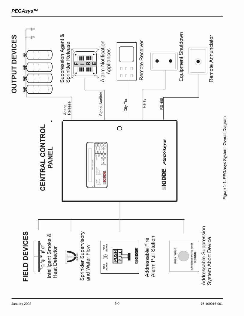

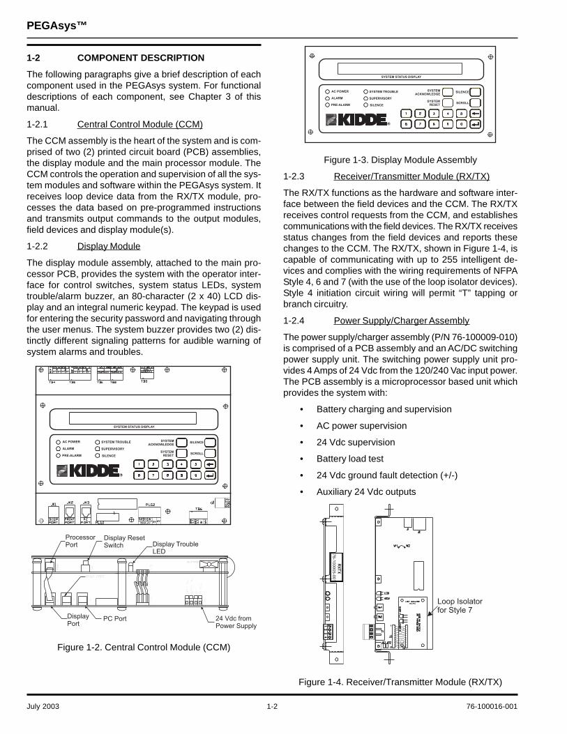
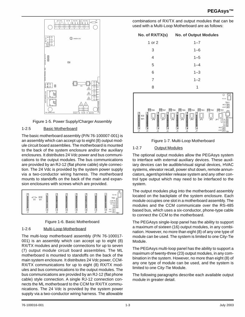
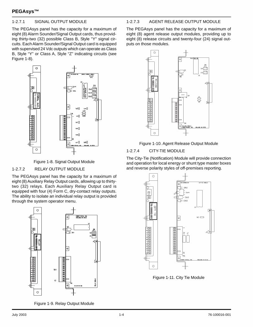
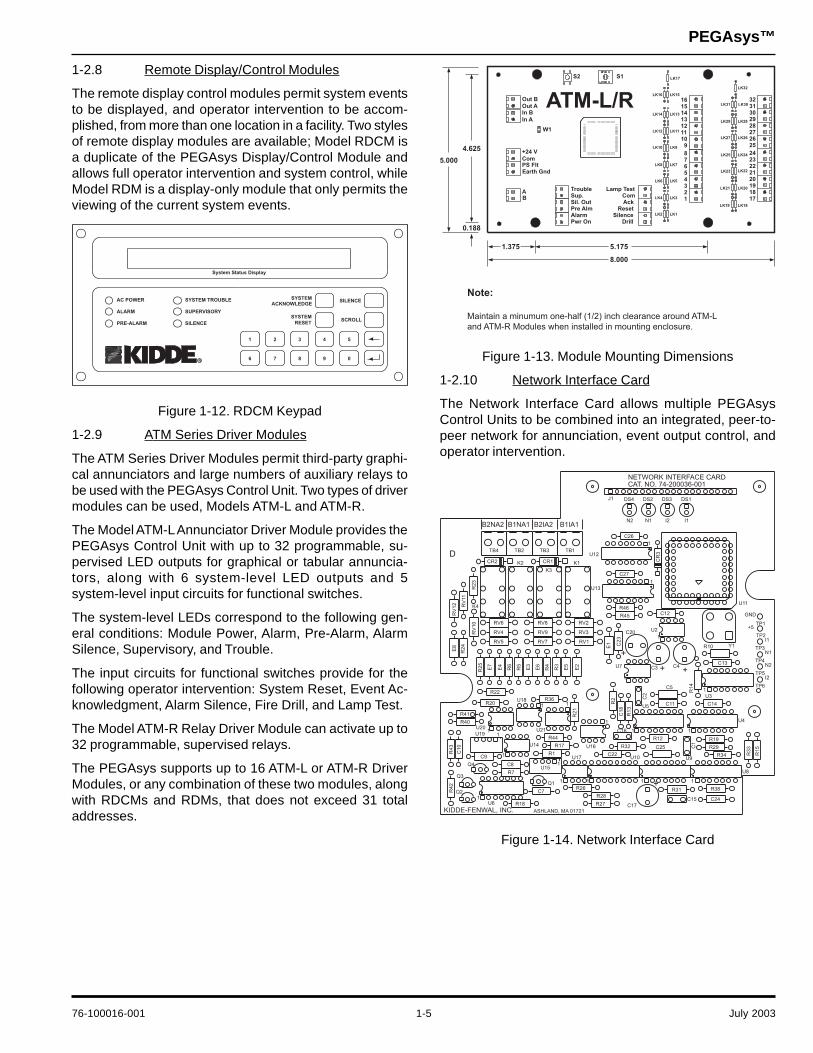
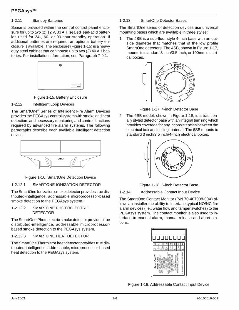
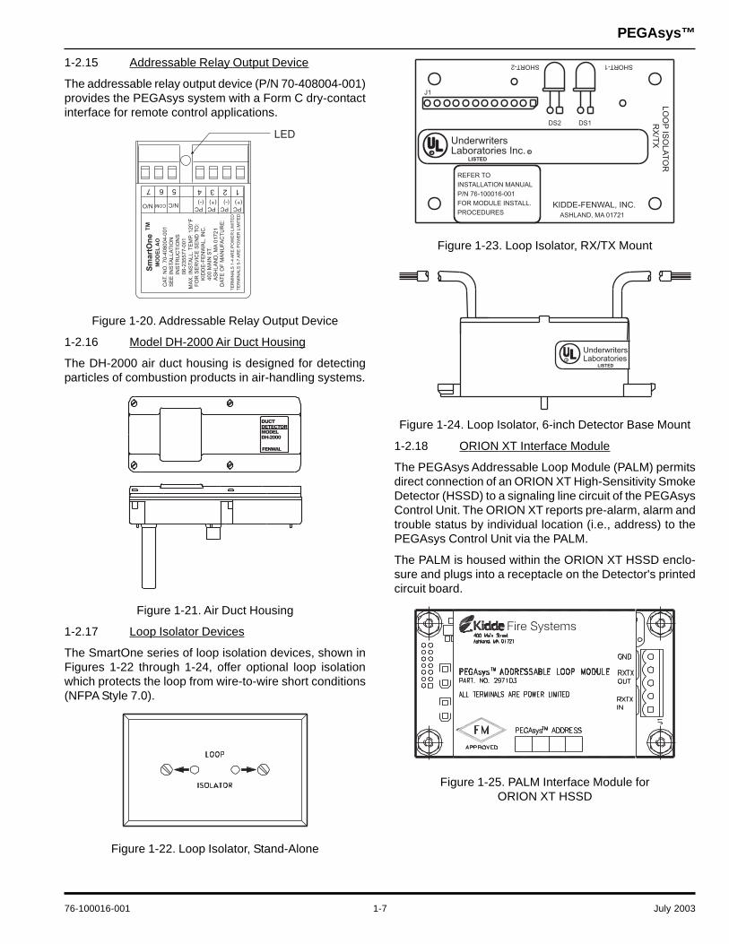
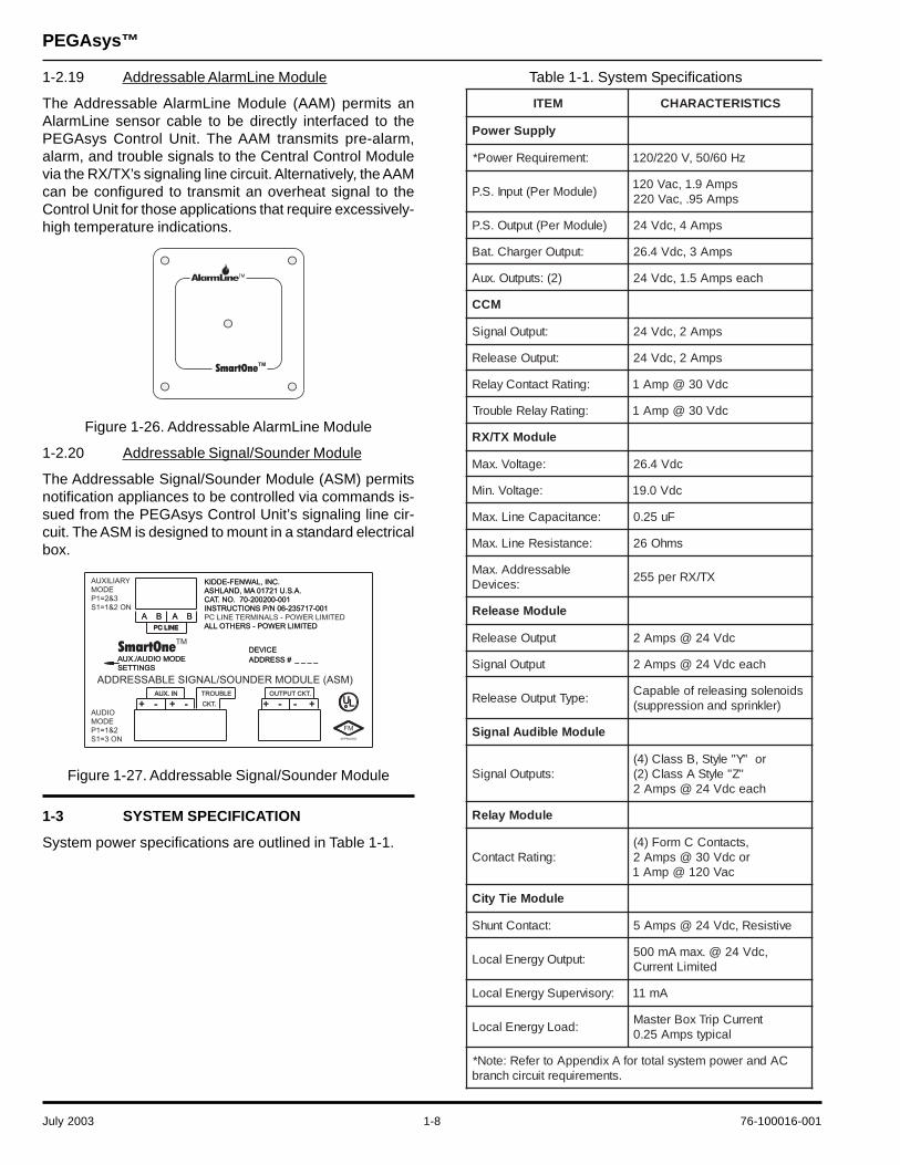
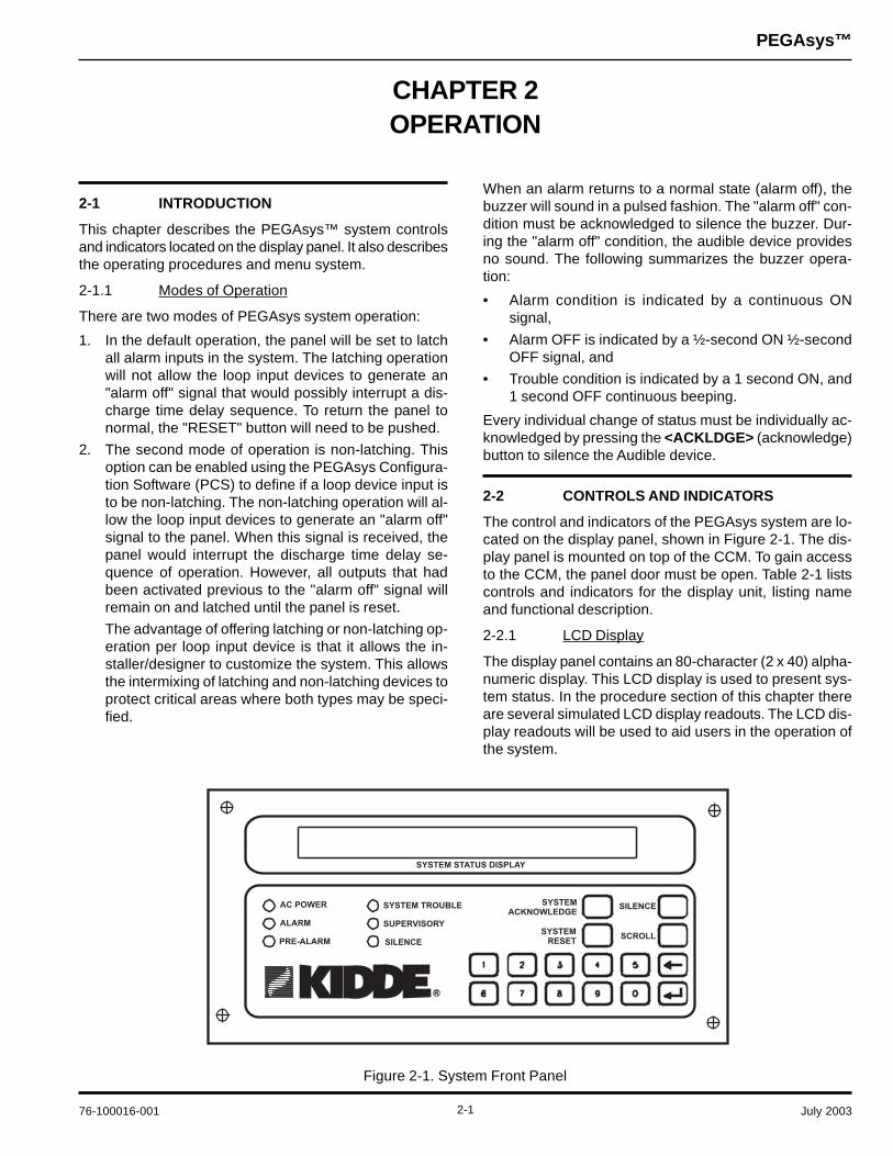
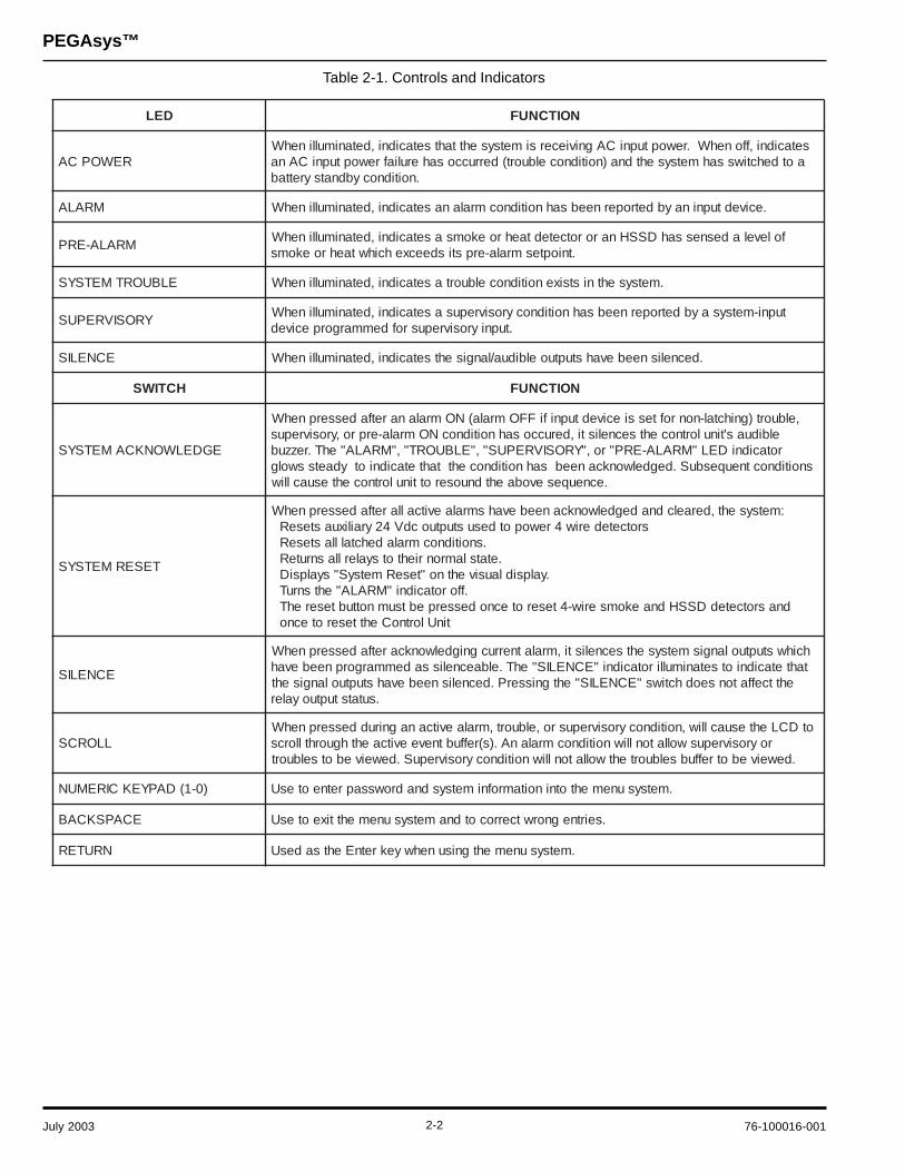


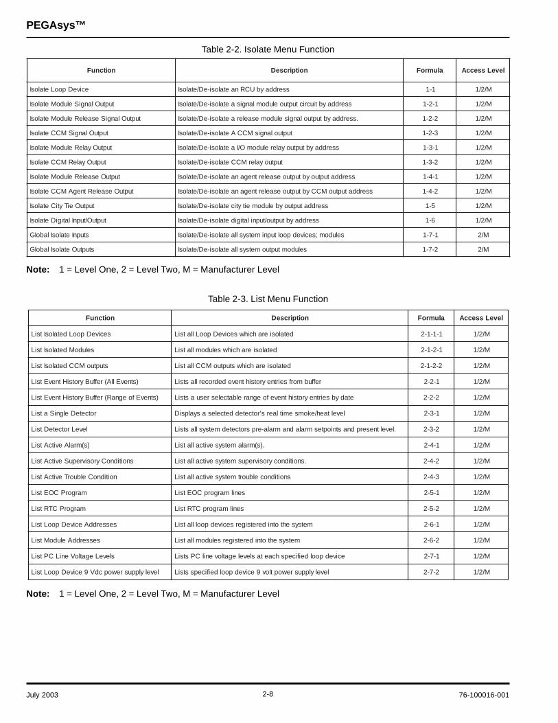
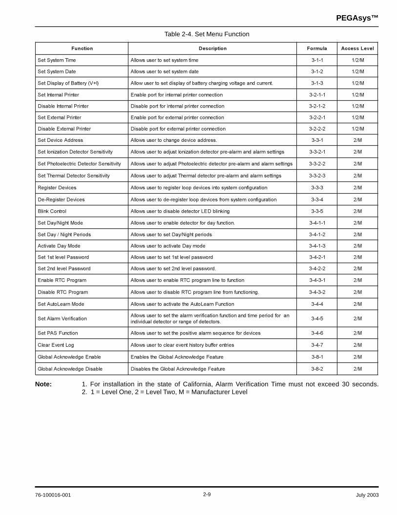


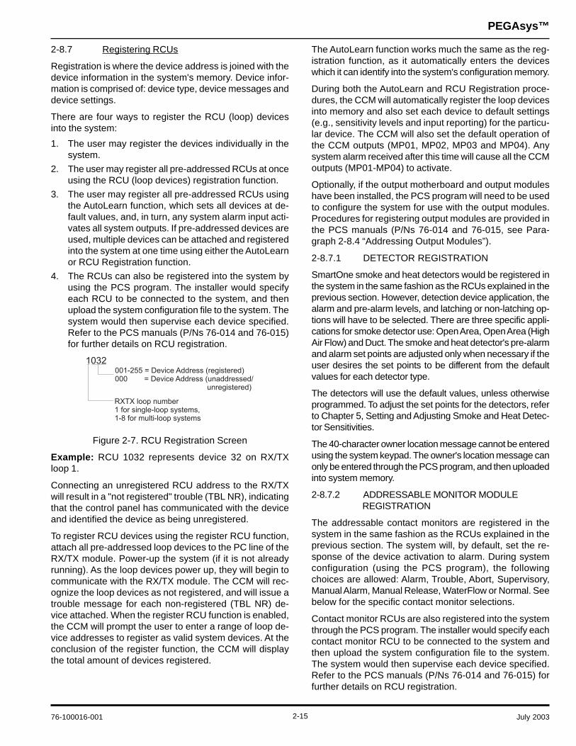

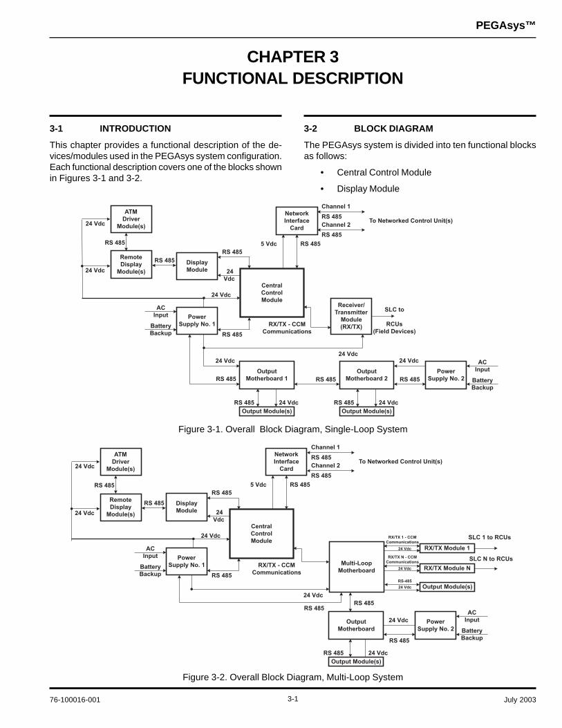
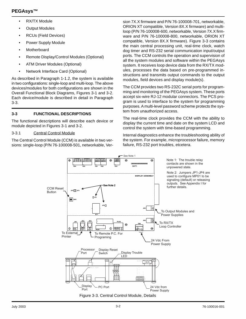
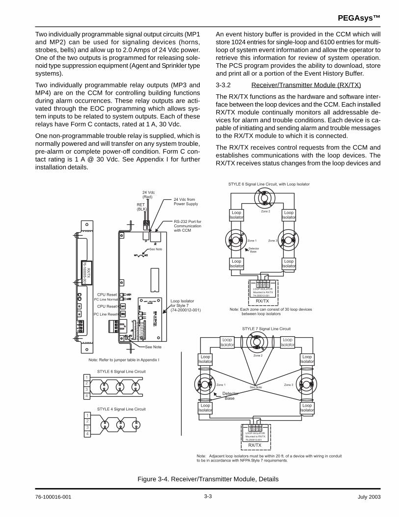
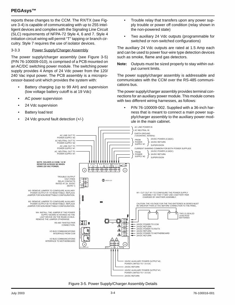
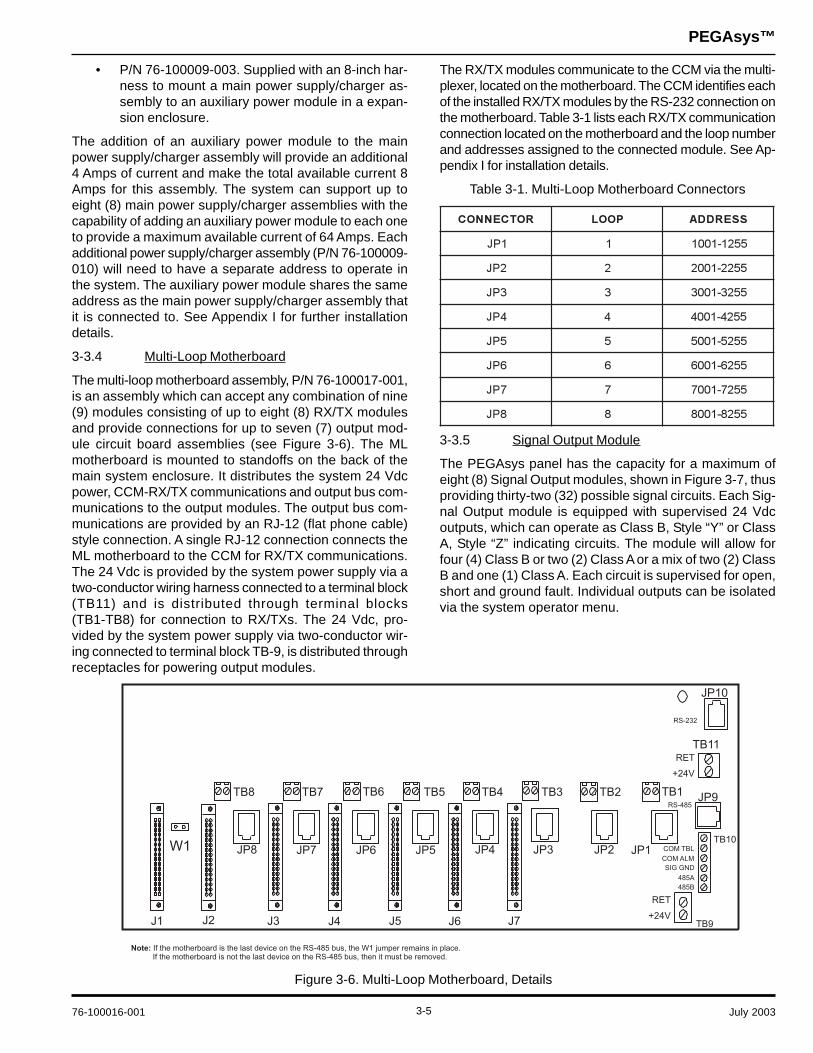
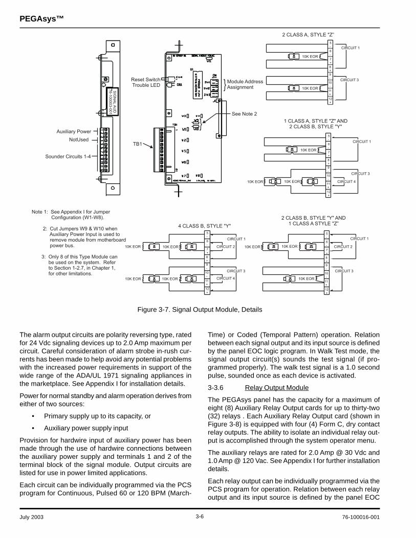

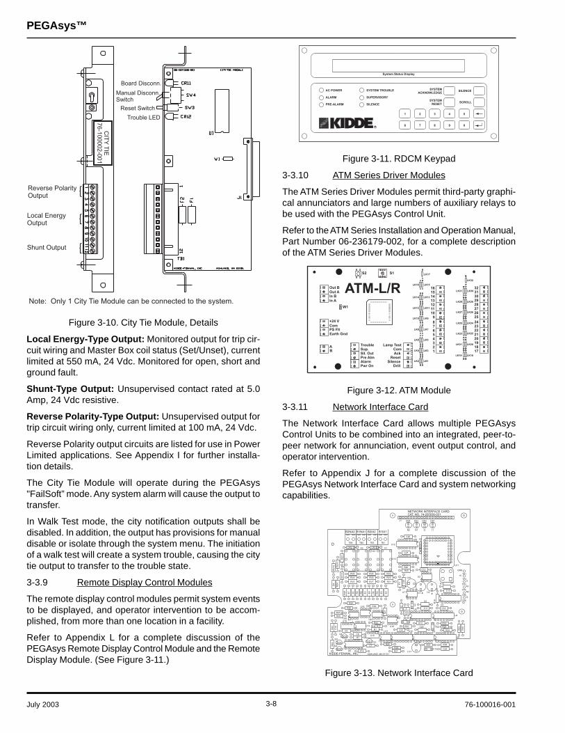
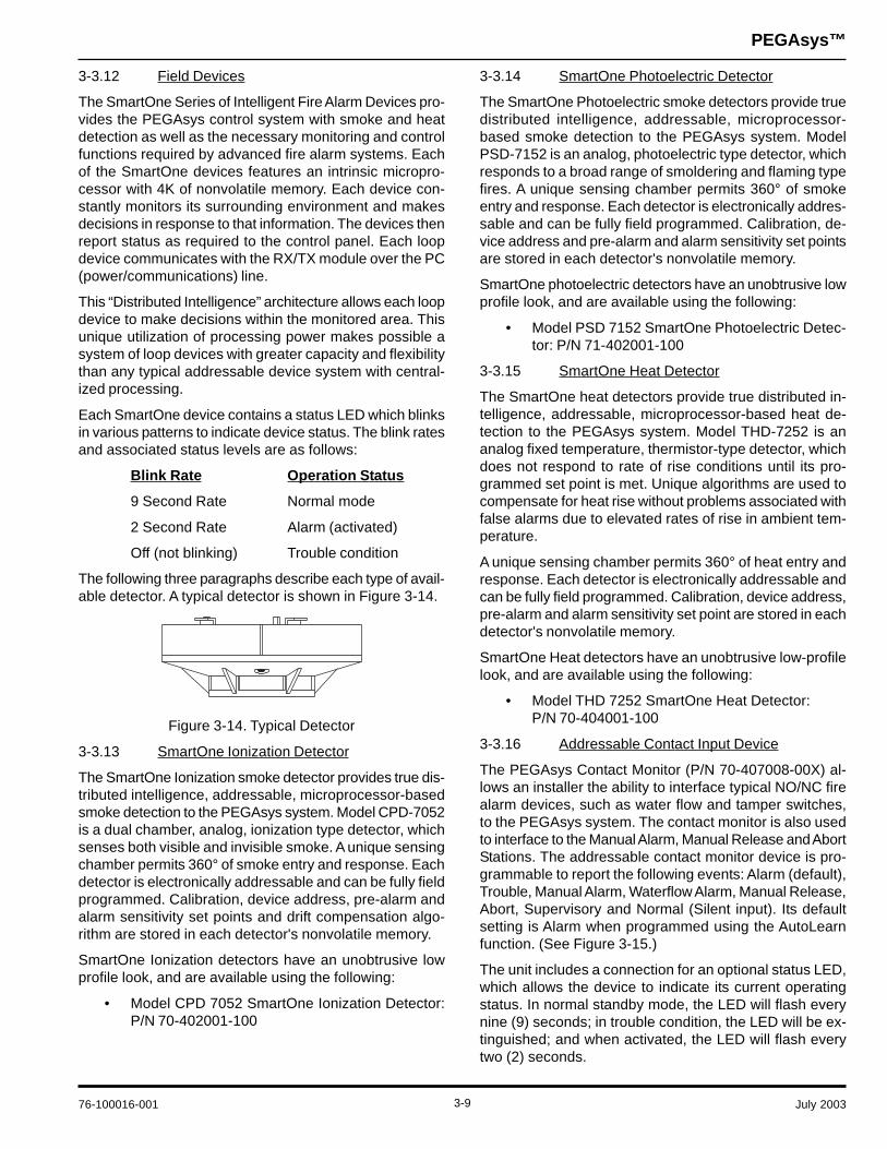
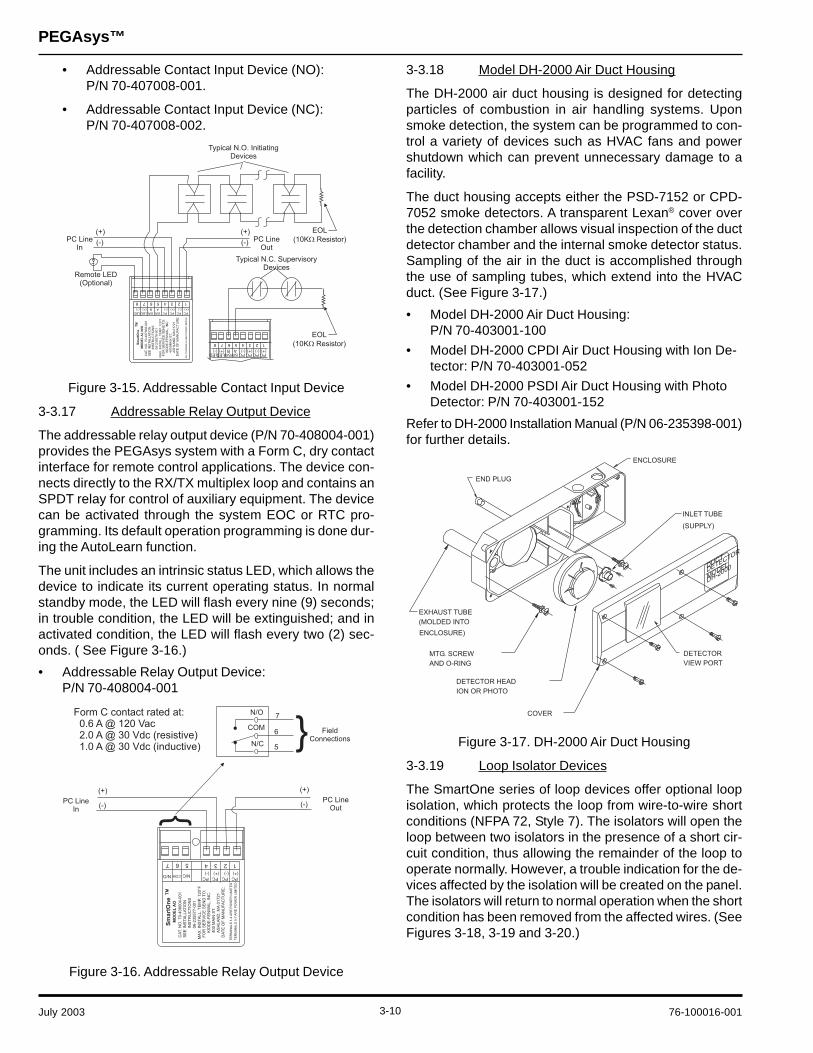
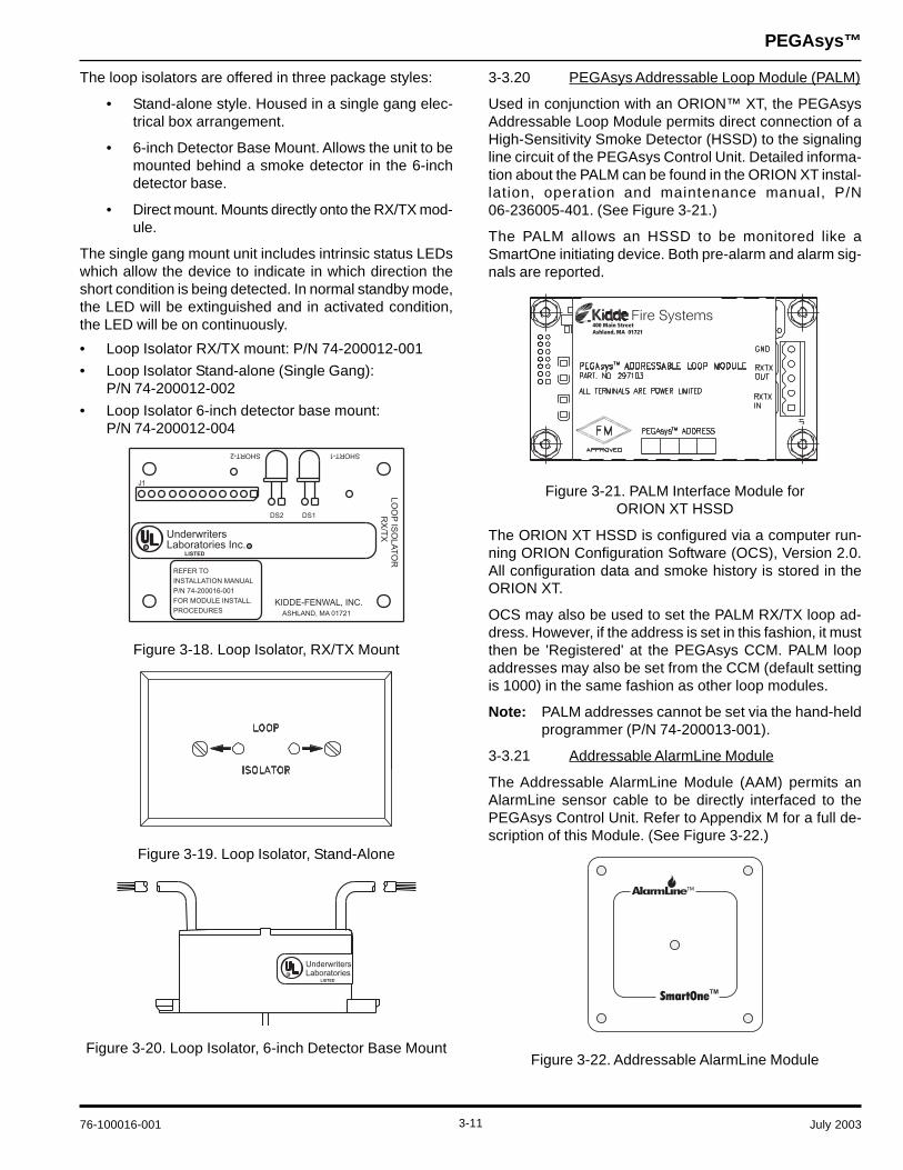
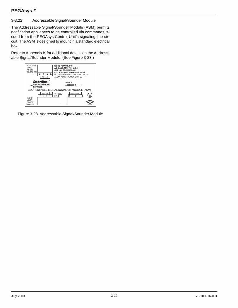


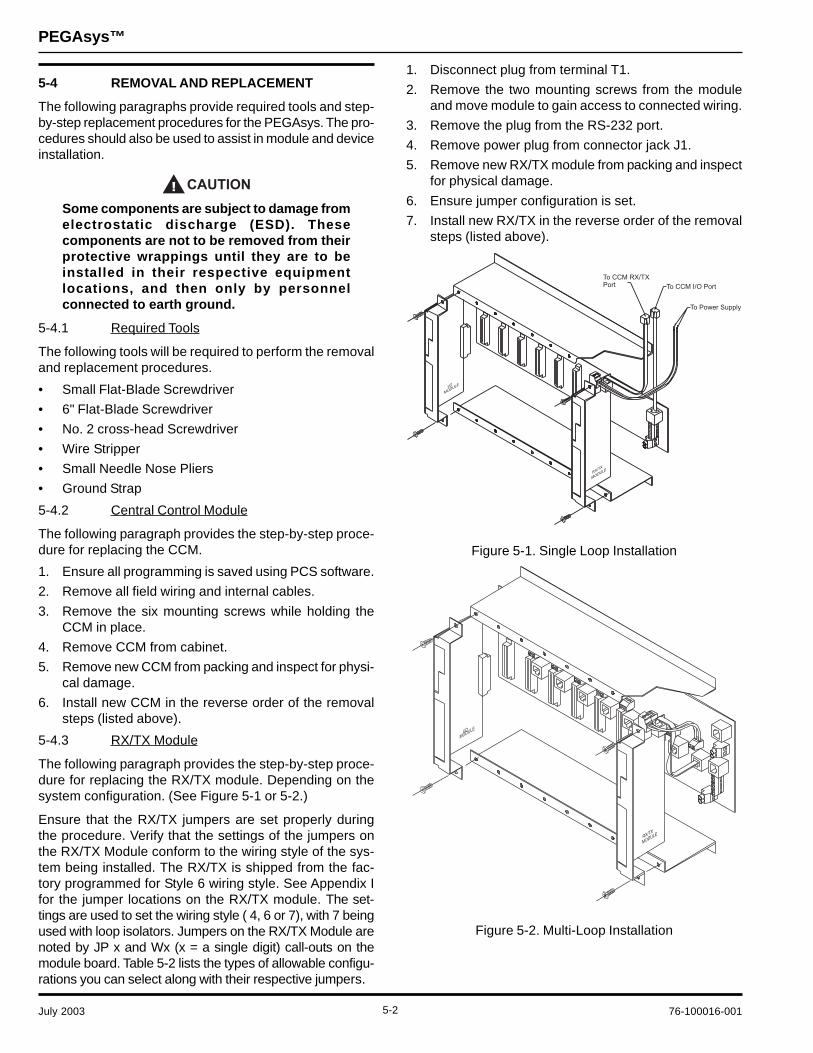


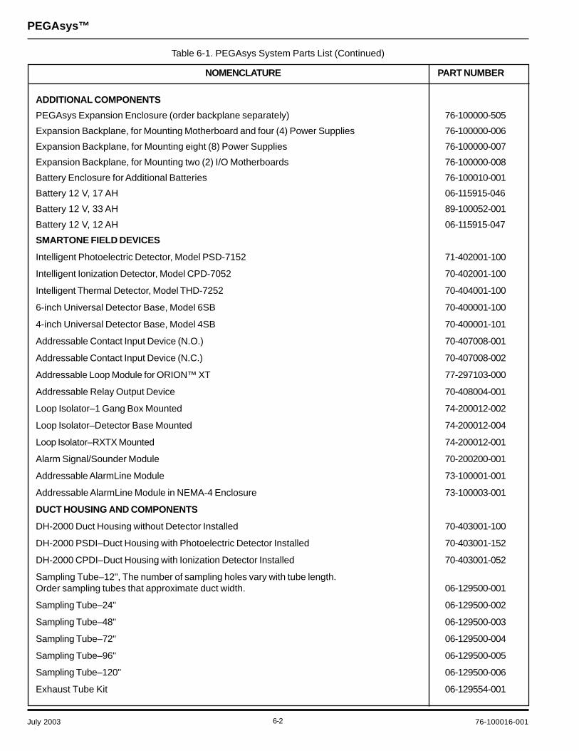
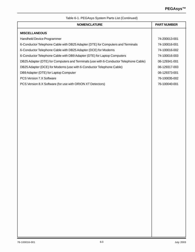


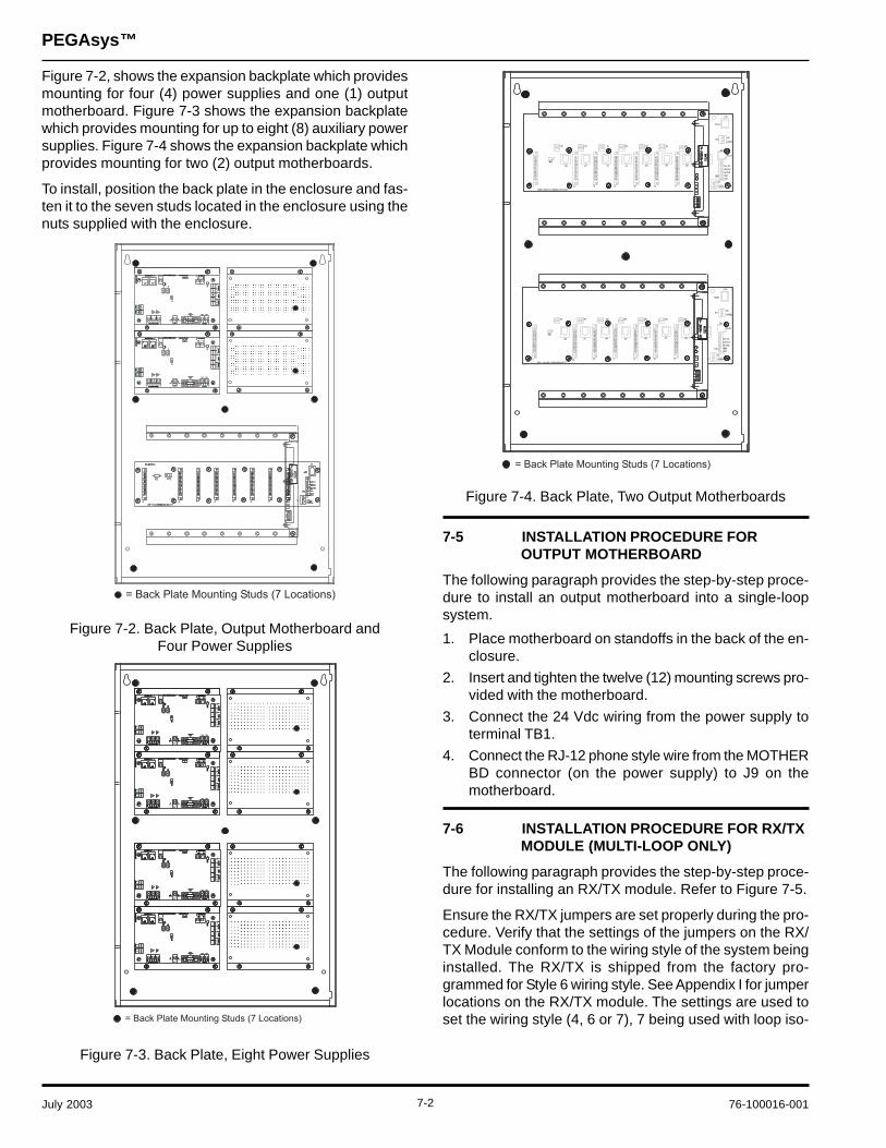
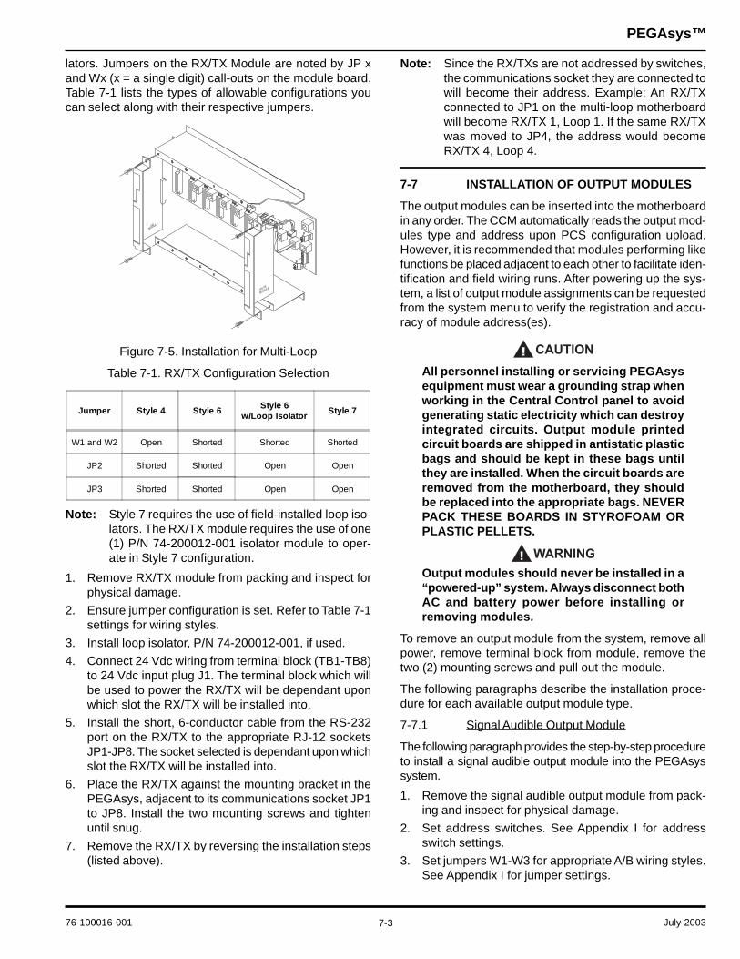

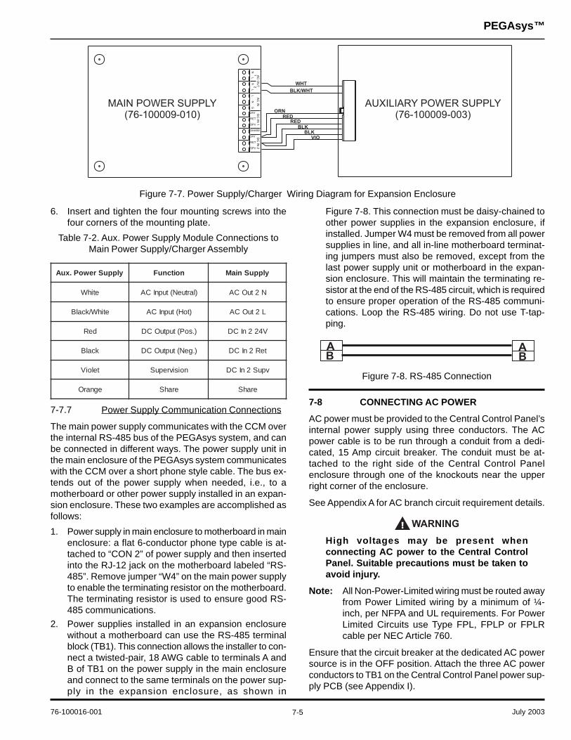
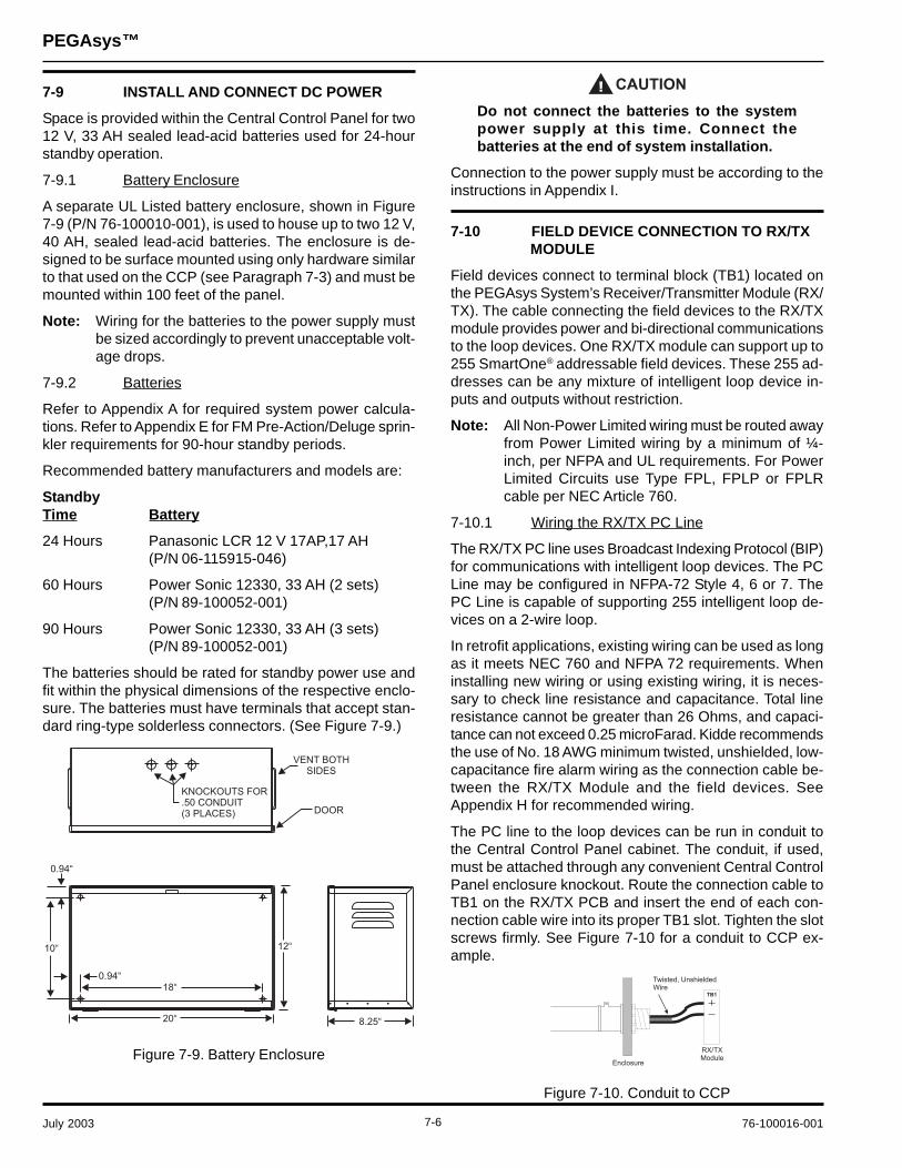
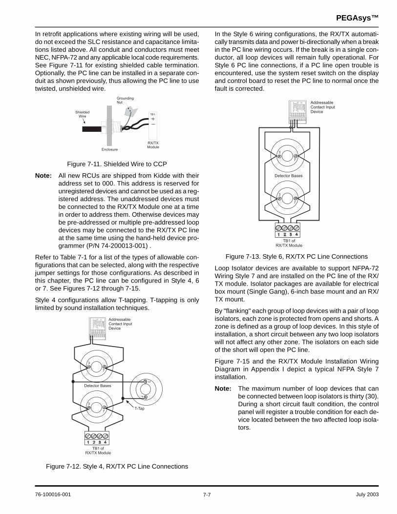
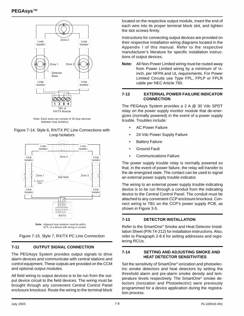


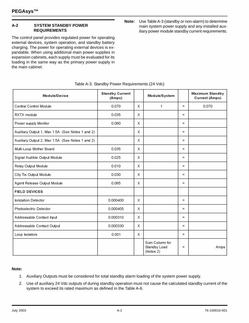

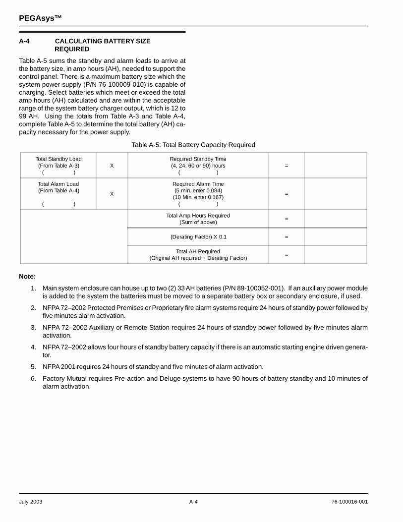

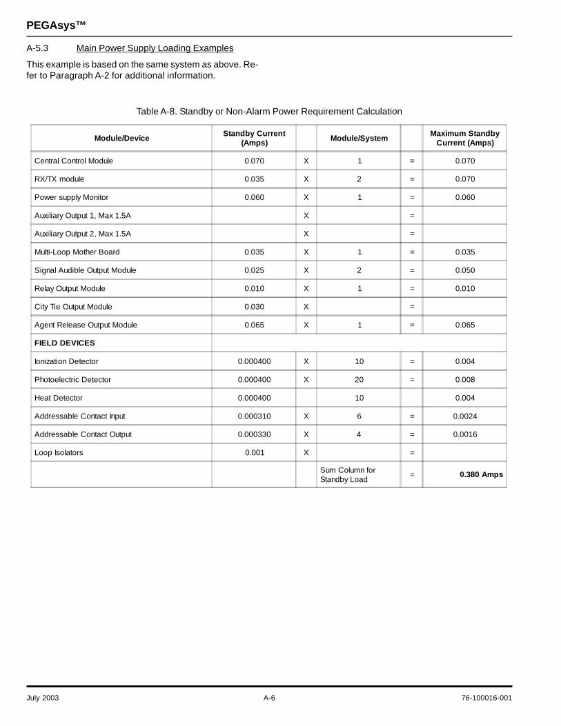
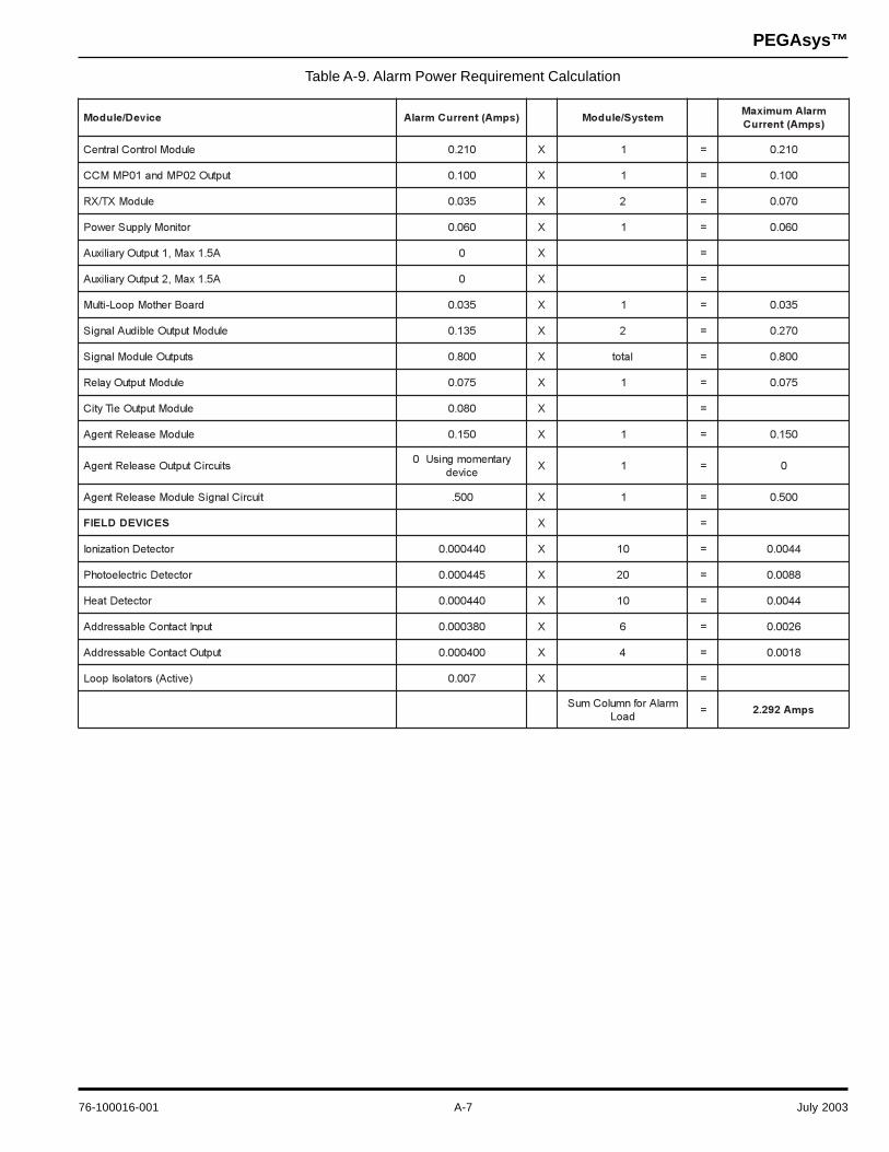
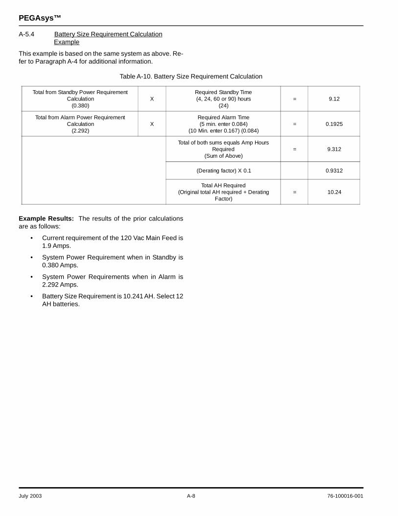
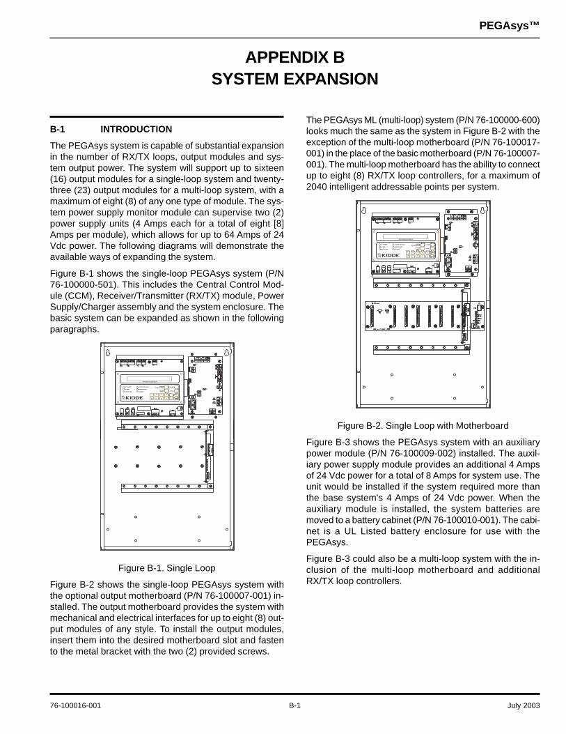
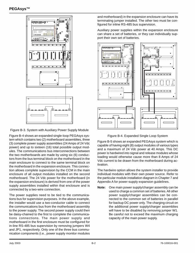
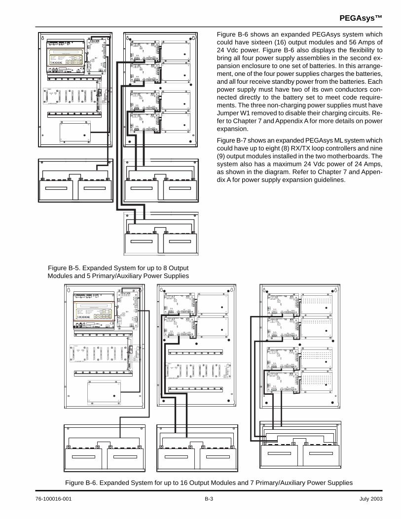
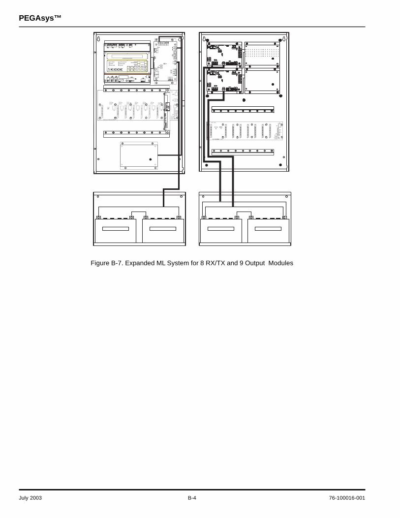
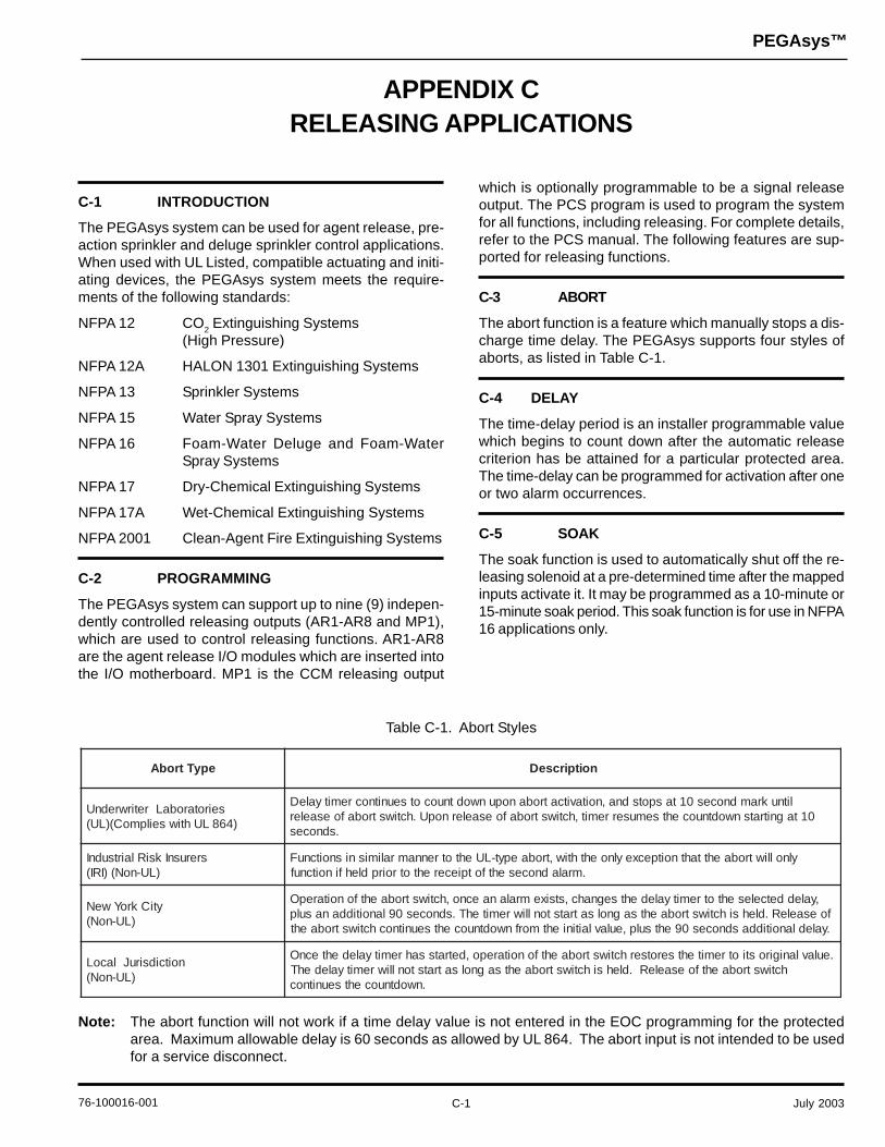
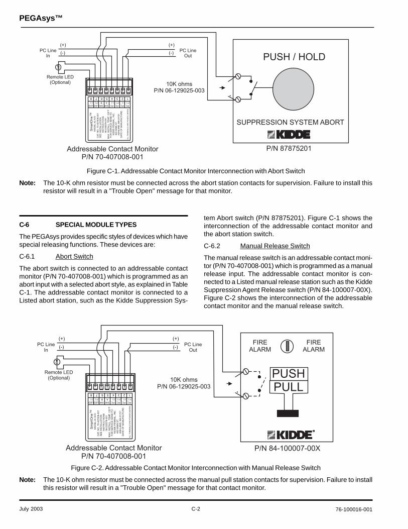
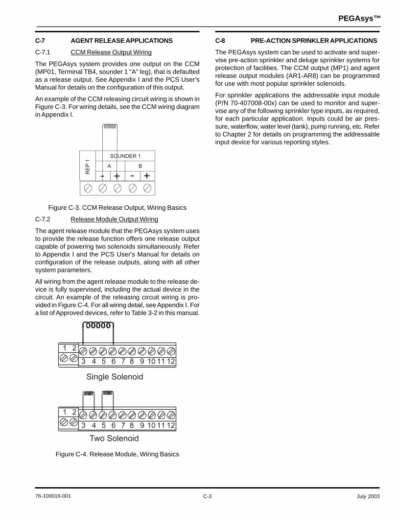


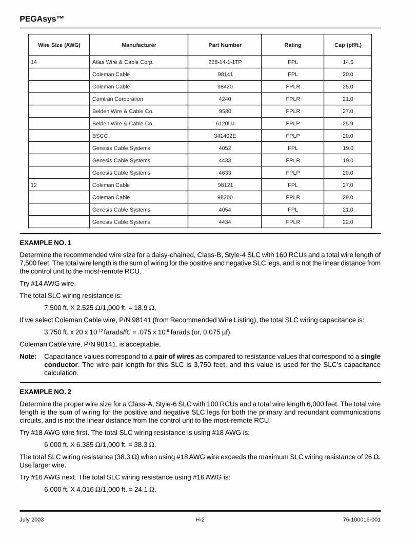


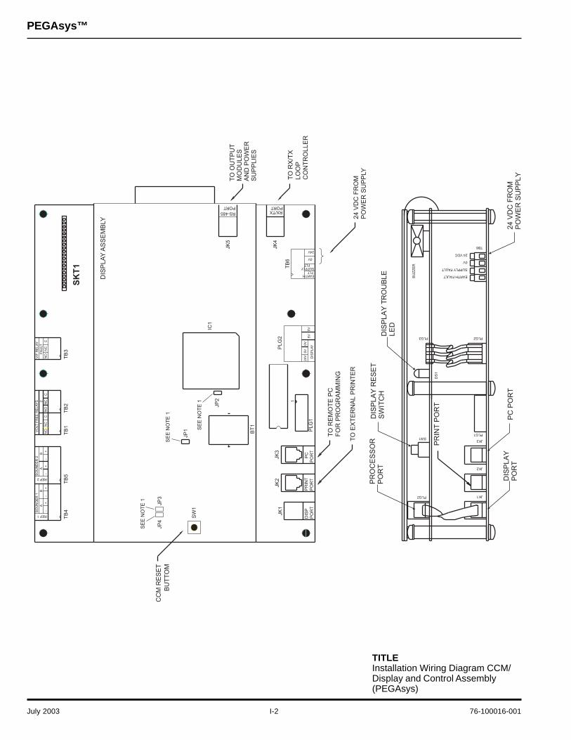
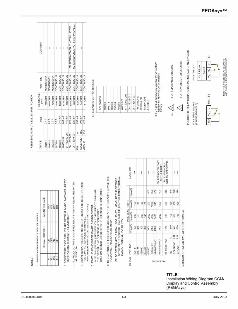
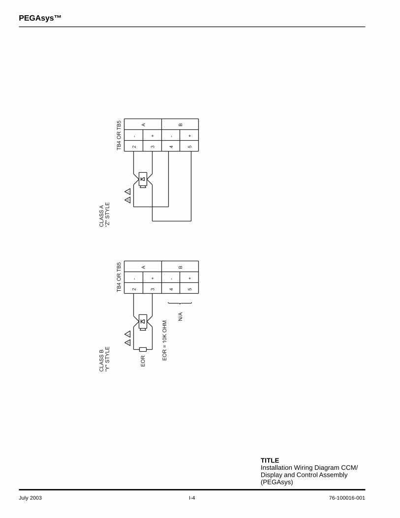
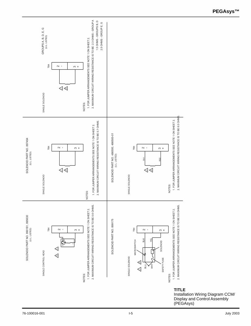
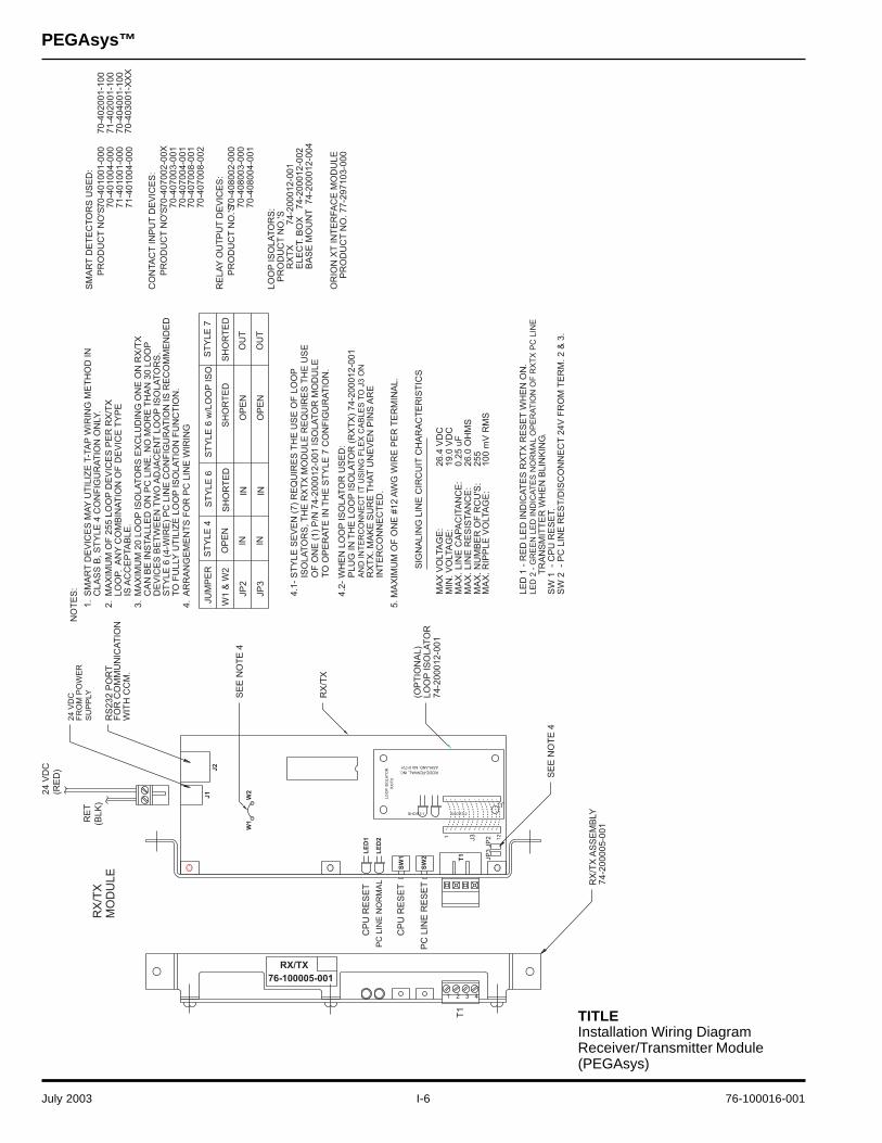
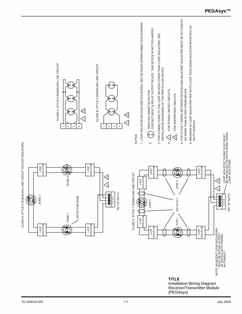
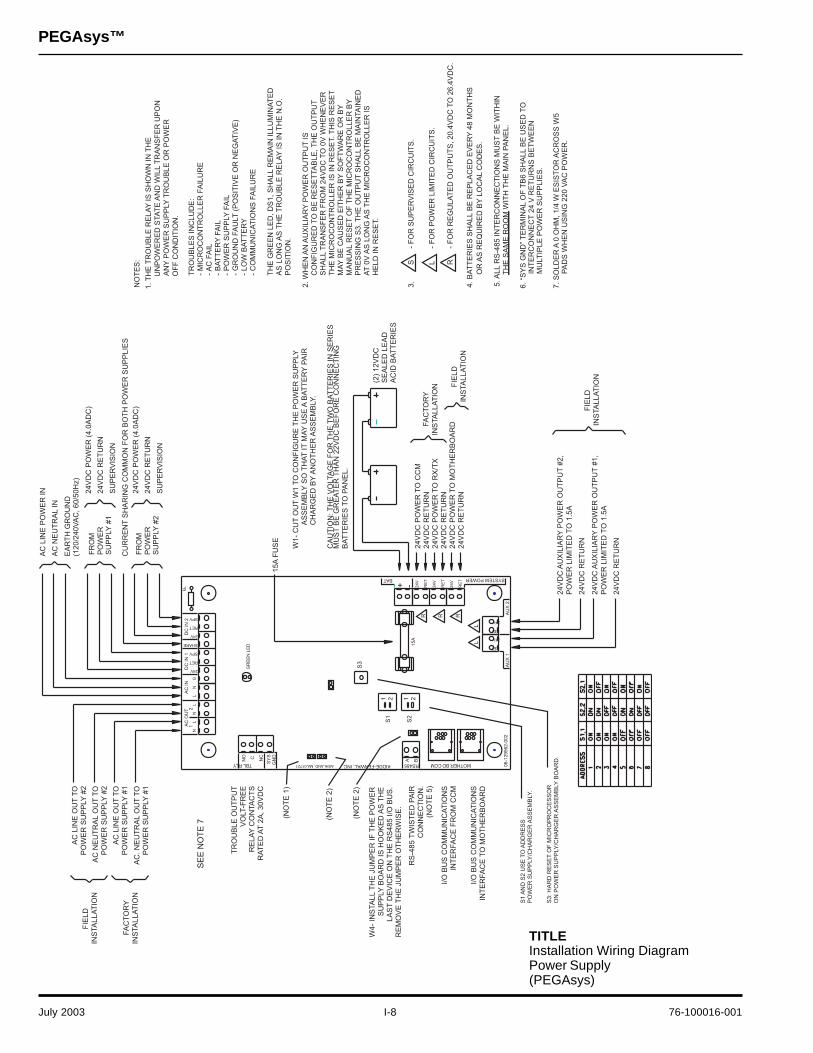
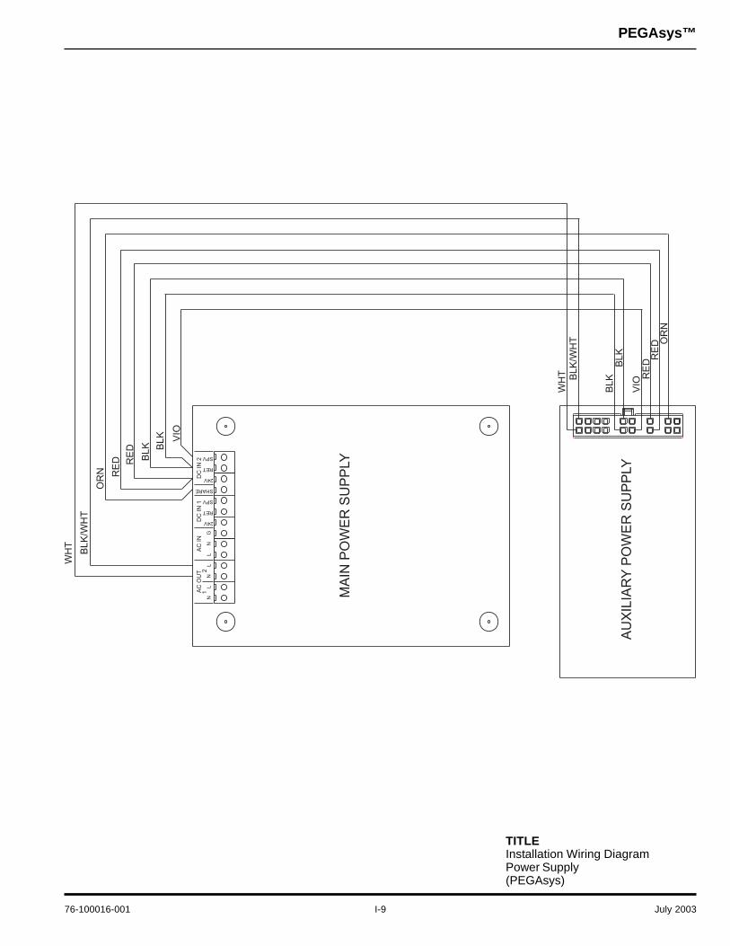
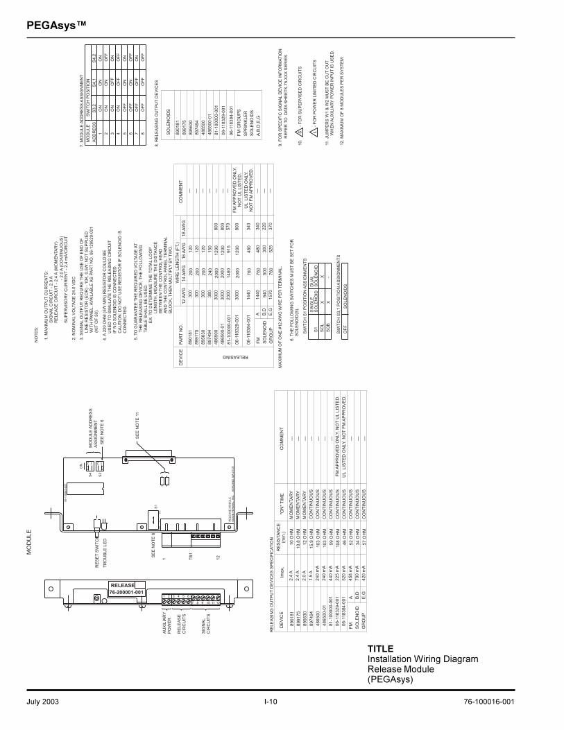
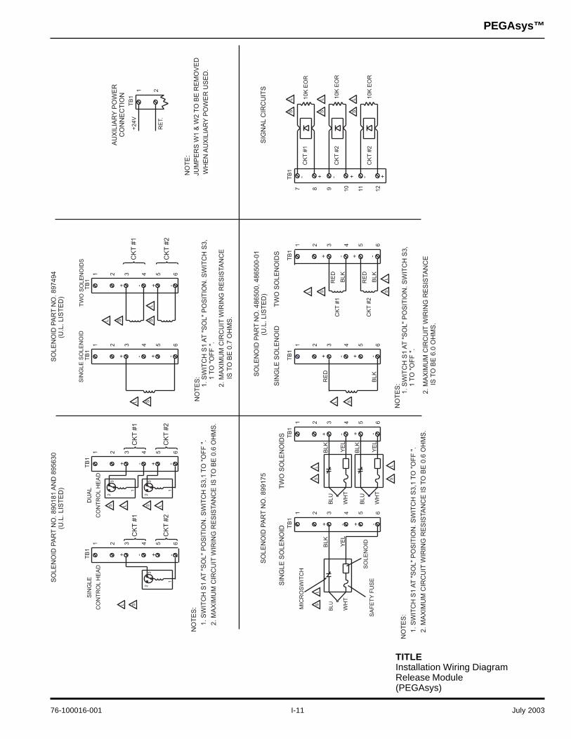
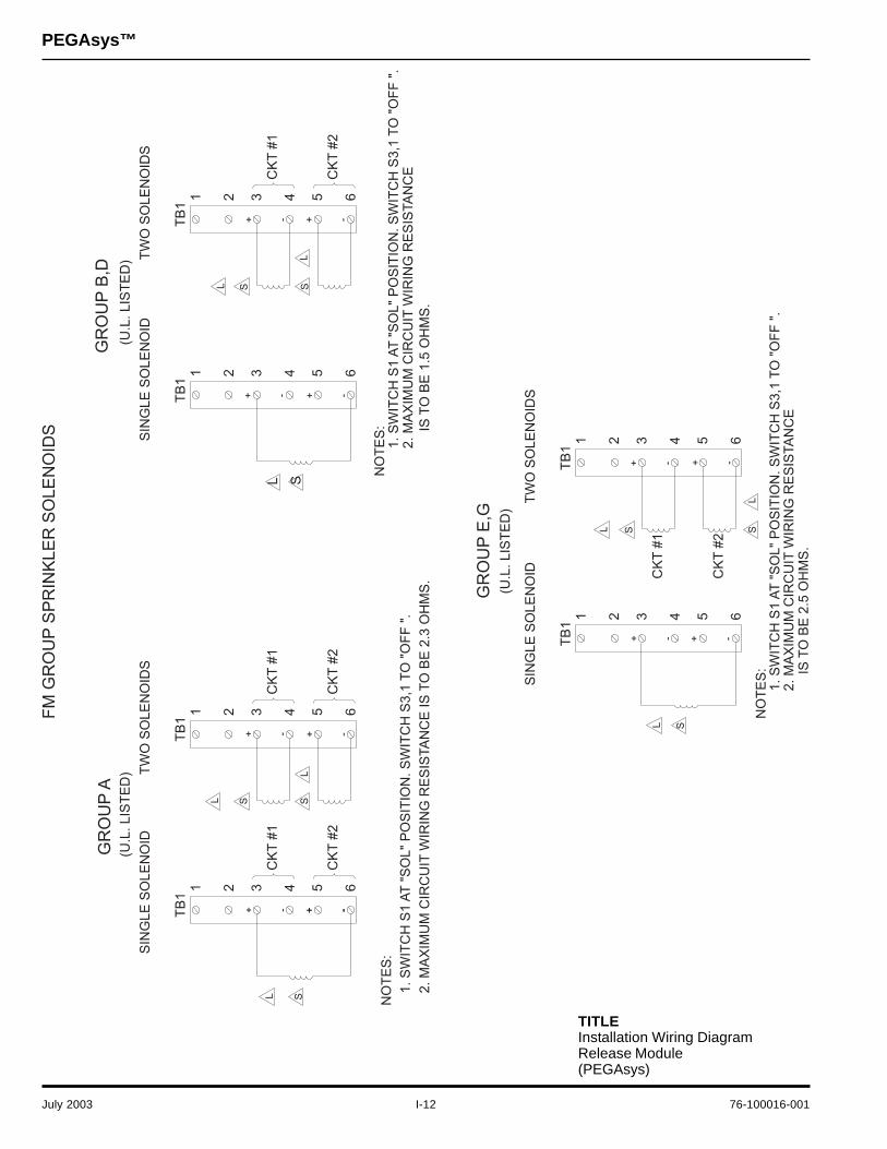
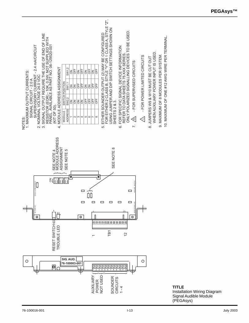
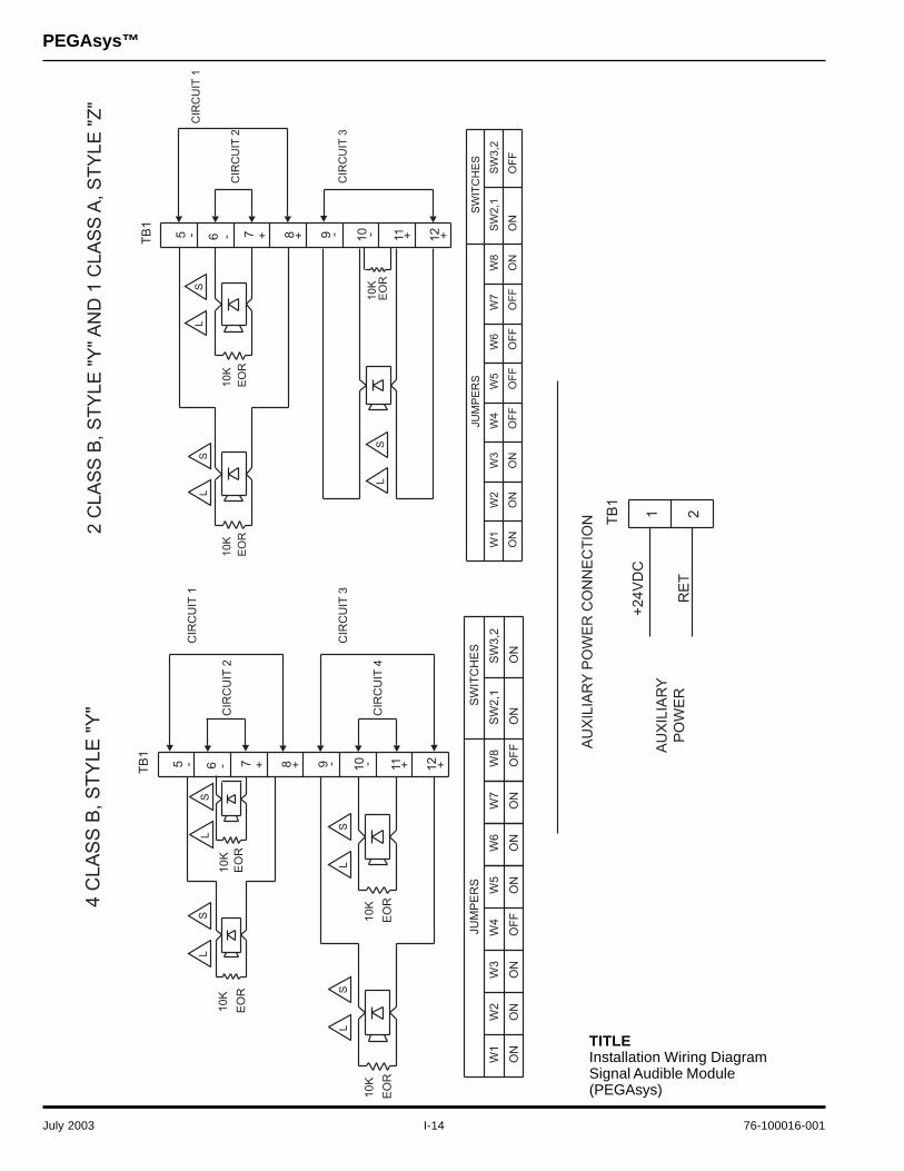
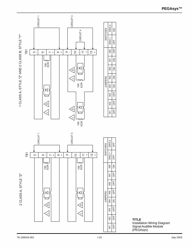
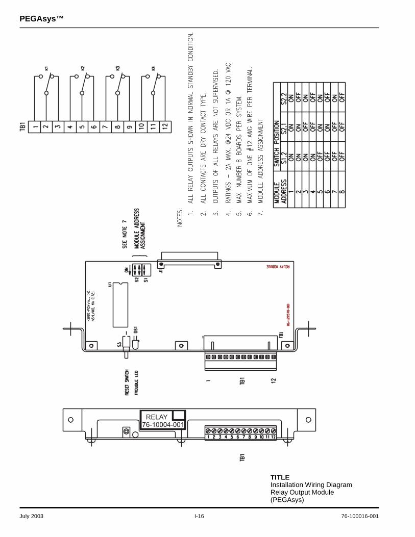
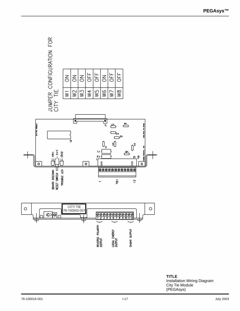
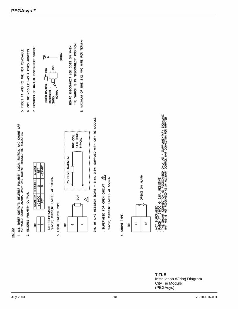
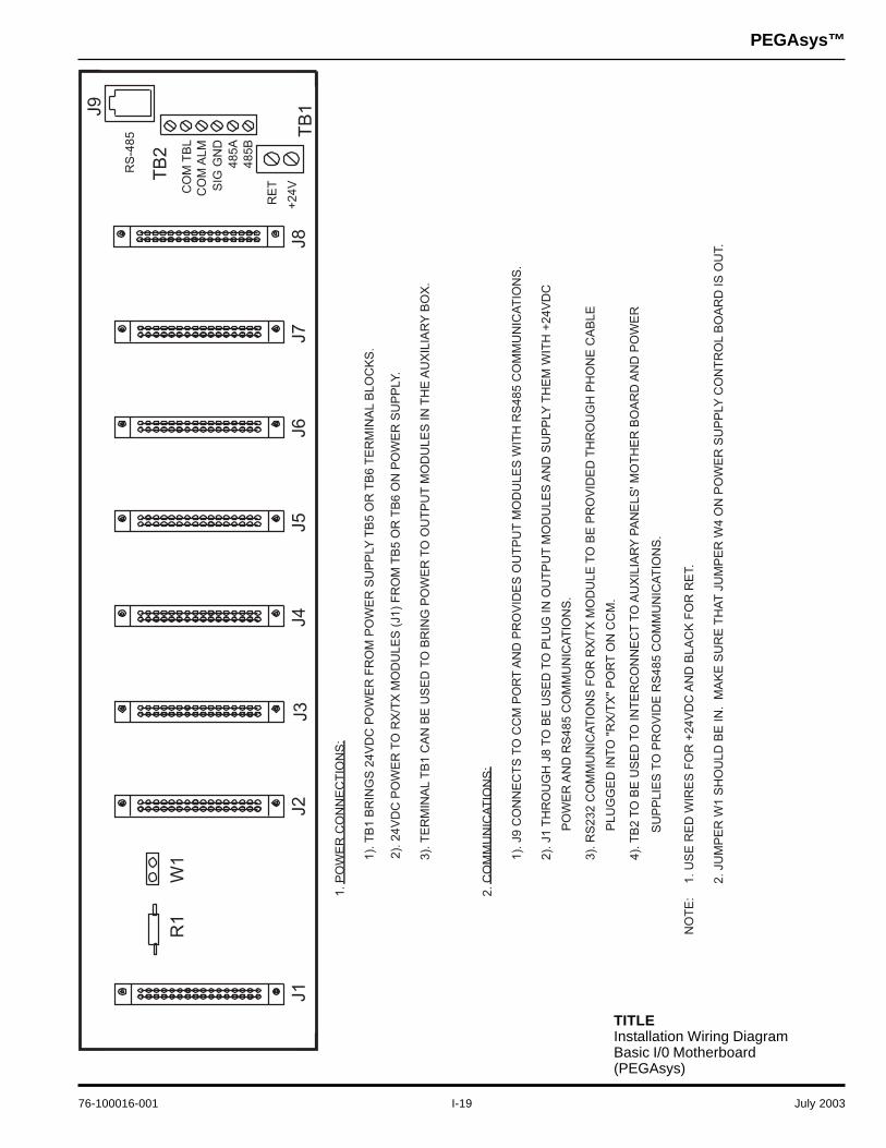
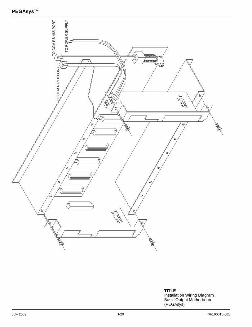
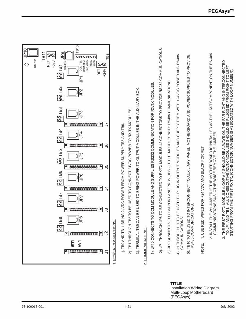
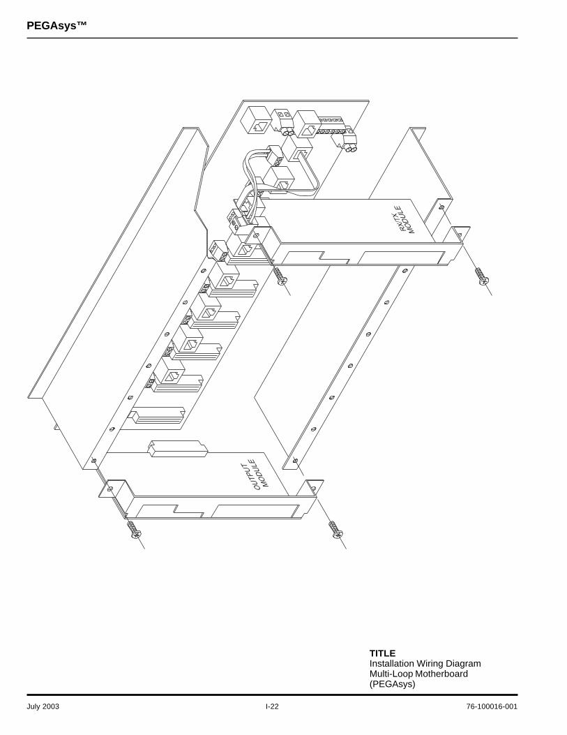

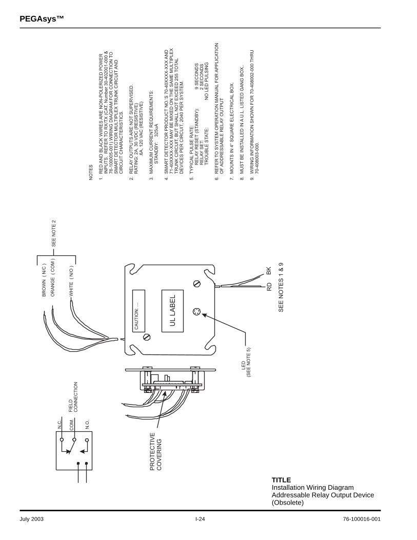
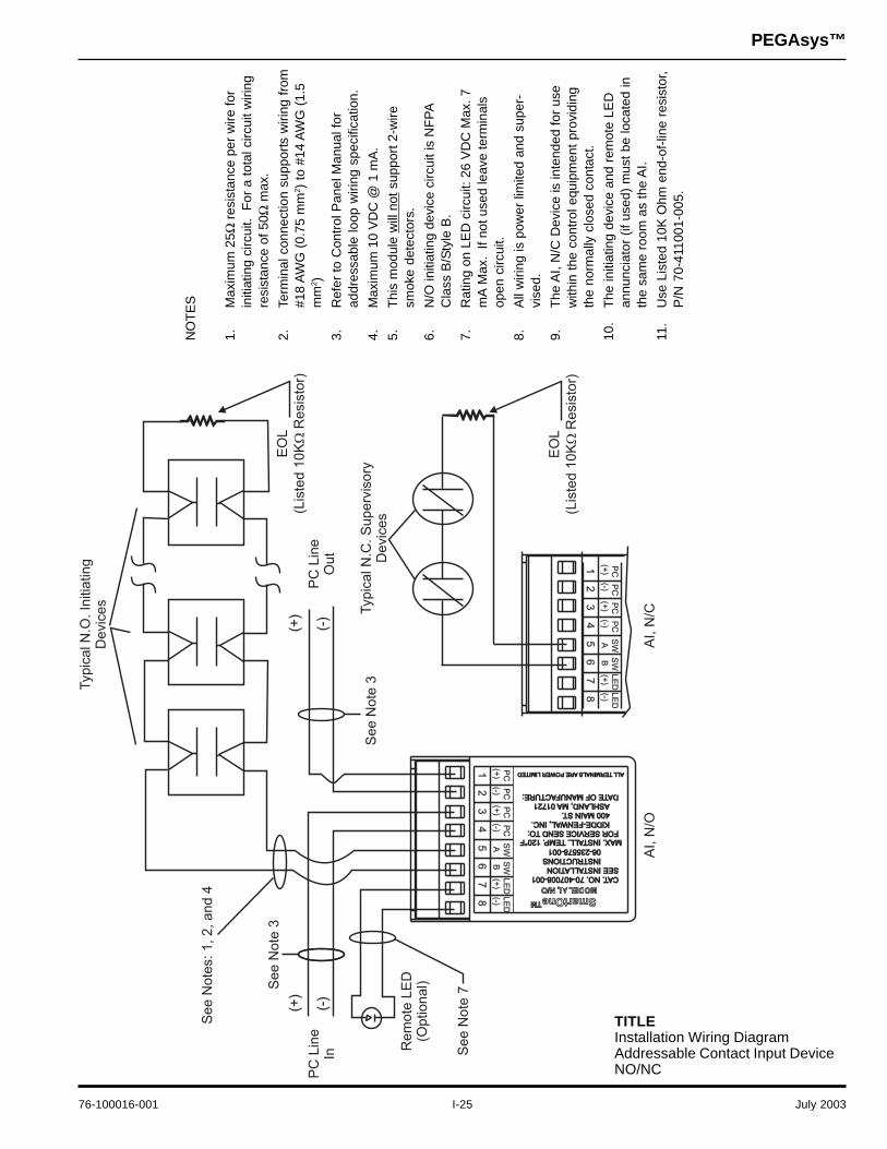
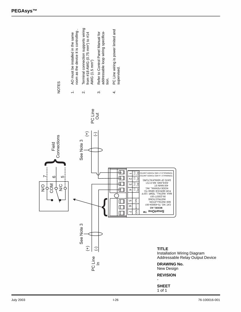
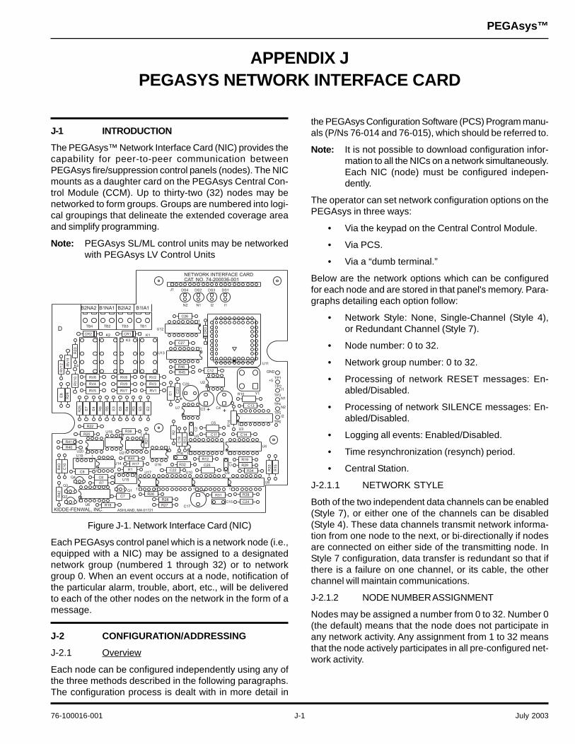
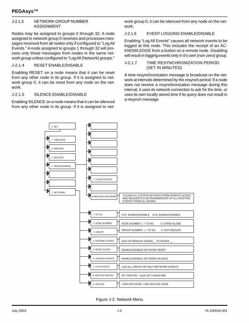

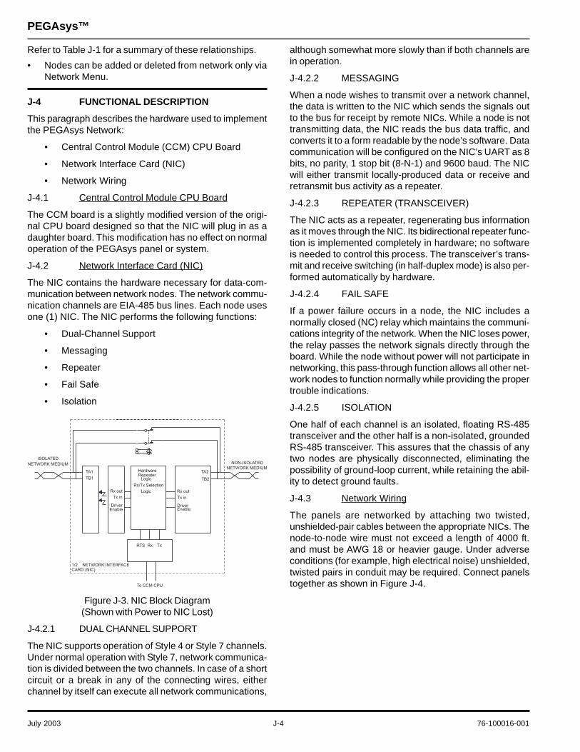
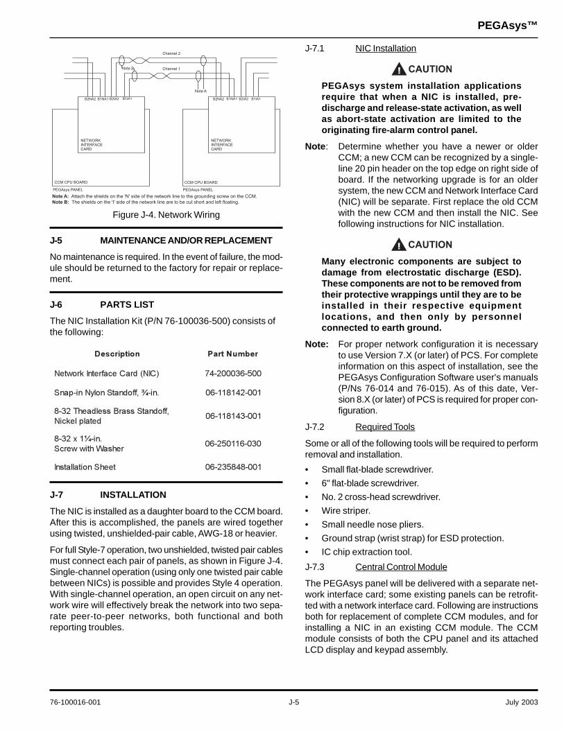
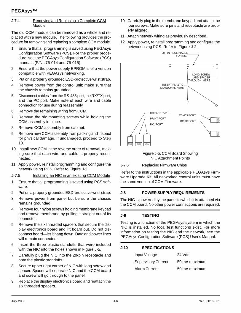
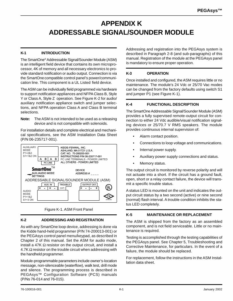
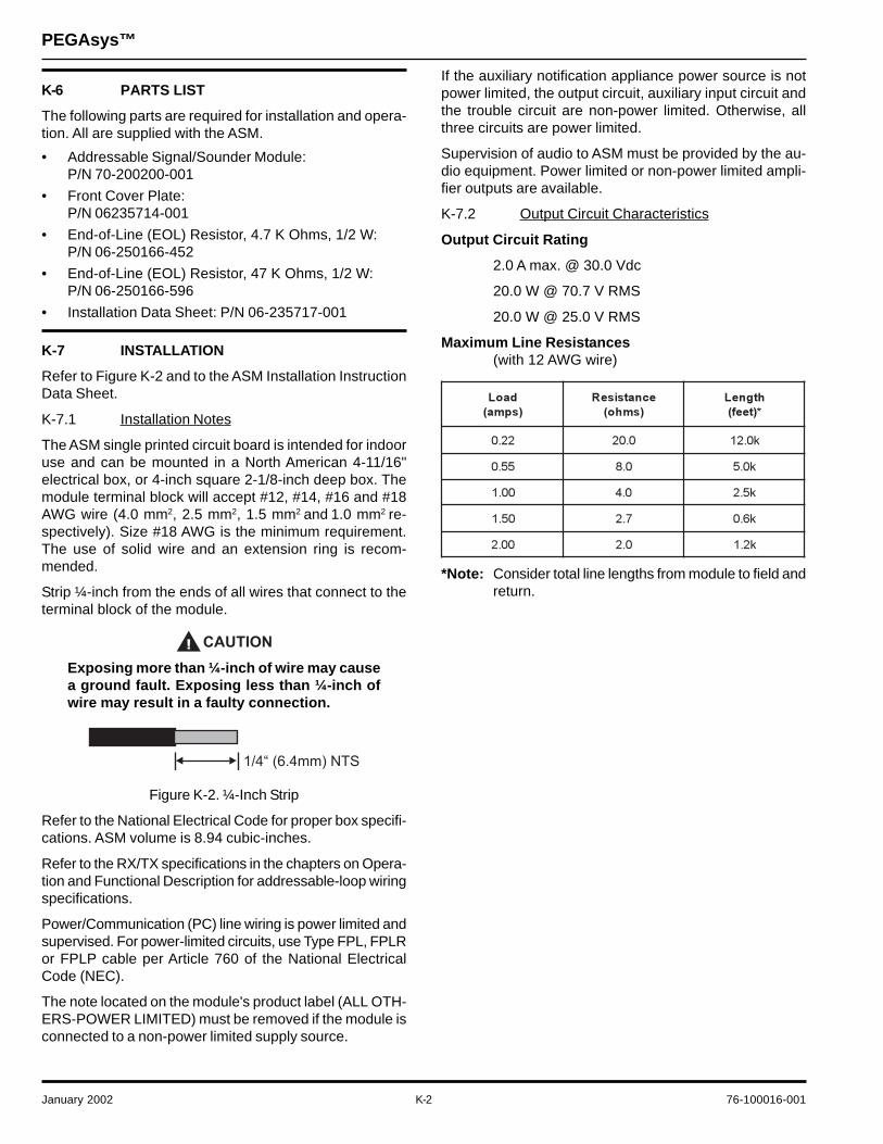
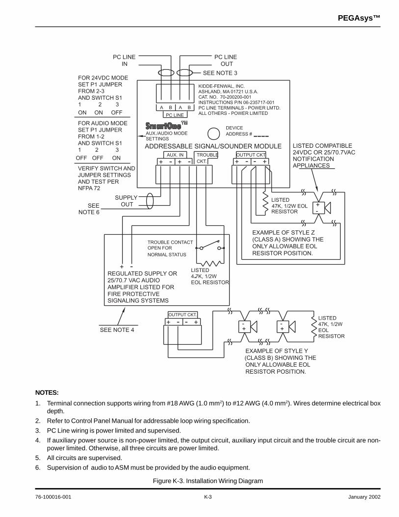

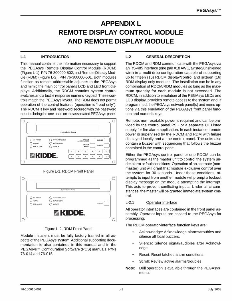
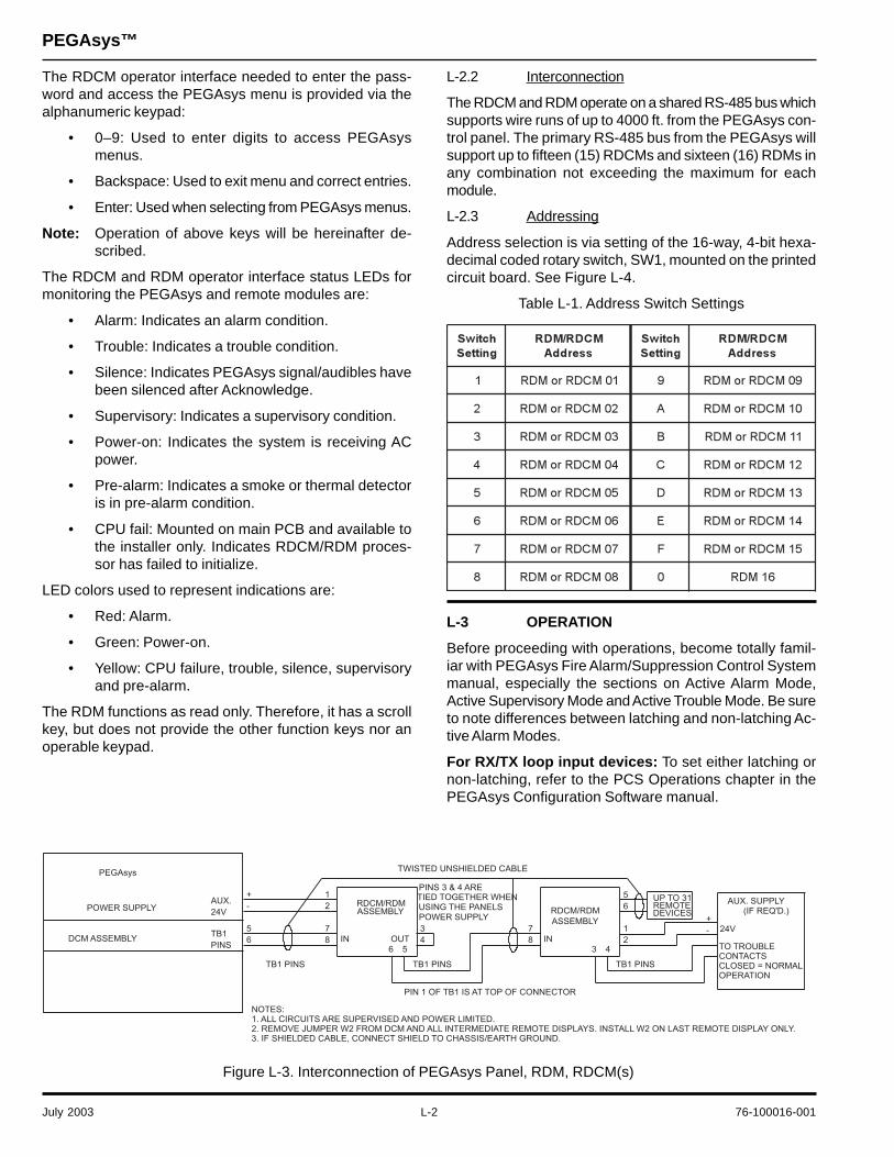


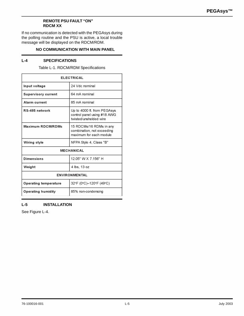
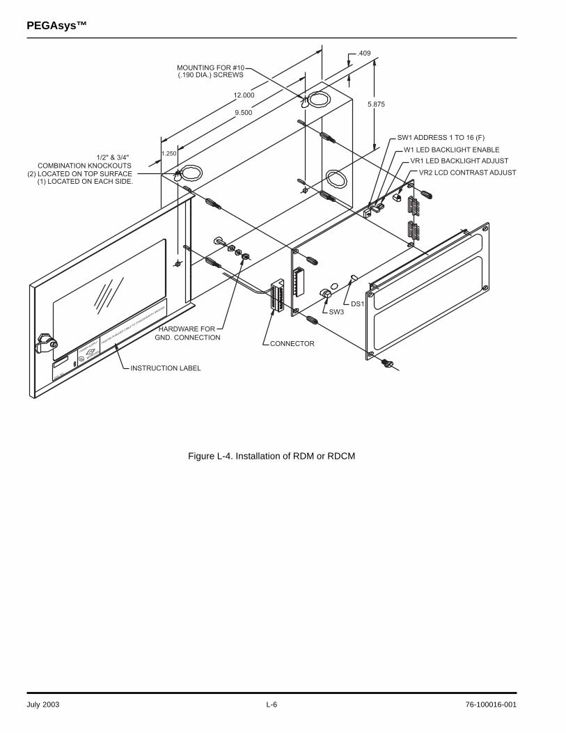
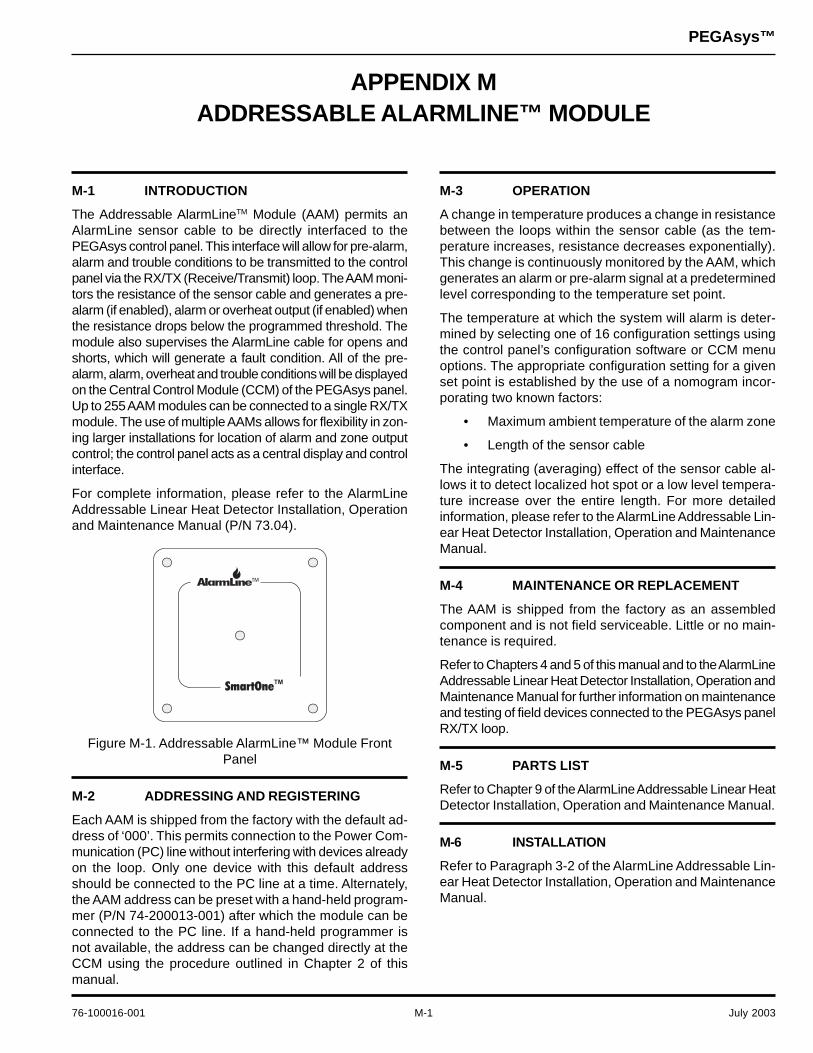

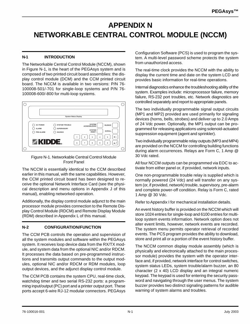

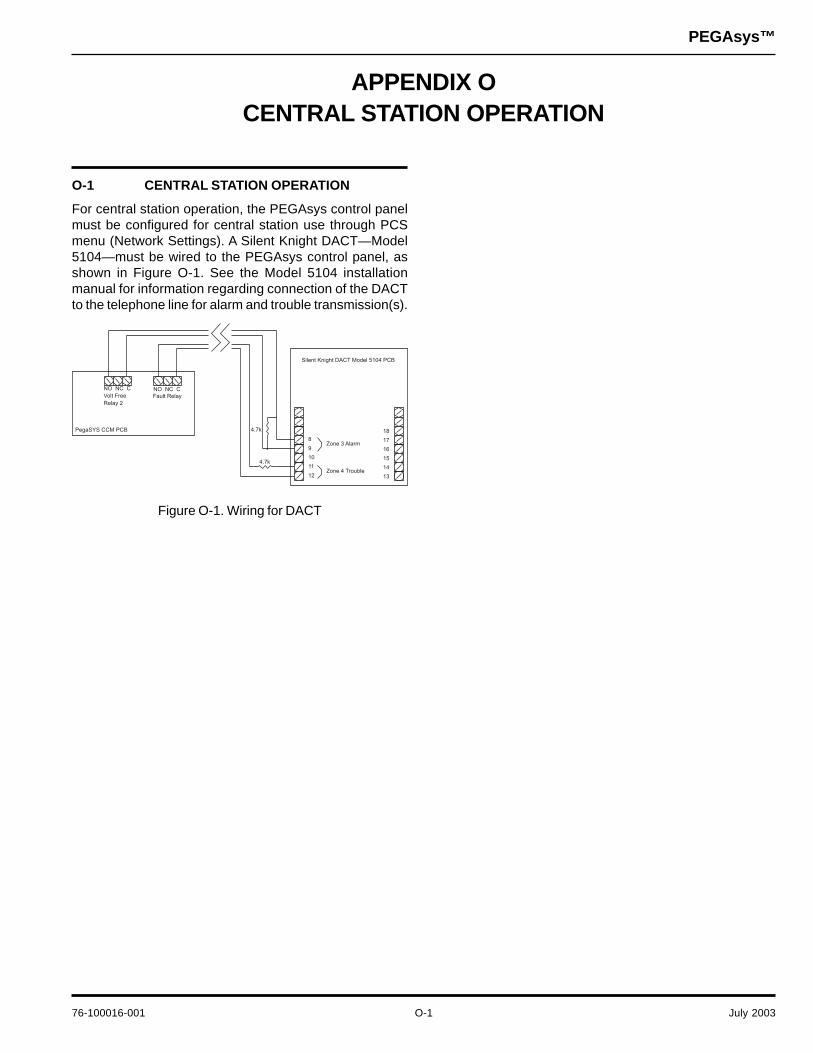


![Copyright c 2007 Pegasys Inc,All rights reserved. · Linear PCM Dolby Digital [Mono/Stereo] PEGASYS Dolby Digital Encoder SDK Encoder DATA DATA DATA Dolby](https://static.documents.pub/doc/80x56/5d676a0d88c993d5408b7516/copyright-c-2007-pegasys-incall-rights-linear-pcm-dolby-digital-monostereo.jpg)


