1Key Laboratory of Optical Fiber Sensing and Communications (Education Ministry of China), University of Electronic Science andTechnology of China, Chengdu 611731, China2Research Centre of Optical Fiber Sensing, Zhejiang Laboratory, Hangzhou 310000, China3Optical Fiber Co., Ltd., ZTT Group, Nantong 226009, China4Carbonene Technology Co., Ltd, Deyang 618000, China5Optical Science and Technology Ltd., China National Petroleum Corporation, Chengdu 610041, China6Cavendish Laboratory, University of Cambridge, CB3 0HE, UK7Shenyang National Laboratory for Materials Science, Institute of Metal Research, Chinese Academy of Sciences,Shenyang 110016, China
The combination of optical fiber with graphene has greatly expanded the application regimes of fiber optics, from dynamic opticalcontrol and ultrafast pulse generation to high precision sensing. However, limited by fabrication, previous graphene-fiber samplesare typically limited in the micrometer to centimeter scale, which cannot take the inherent advantage of optical fibers—long-distance optical transmission. Here, we demonstrate kilometers long graphene-coated optical fiber (GCF) based on industrialgraphene nanosheets and coating technique. The GCF shows unusually high thermal diffusivity of 24.99mm2 s-1 in the axialdirection, measured by a thermal imager directly. This enables rapid thermooptical response both in optical fiber Bragg gratingsensors at one point (18-fold faster than conventional fiber) and in long-distance distributed fiber sensing systems based onbackward Rayleigh scattering in optical fiber (15-fold faster than conventional fiber). This work realizes the industrial-levelgraphene-fiber production and provides a novel platform for two-dimensional material-based optical fiber sensing applications.
1. Introduction
Winning the Nobel Prize in physics of 2009, optical fibershave been a cornerstone of global information networks[1]. Besides applications in telecommunication, opticalfiber-based sensing technology possesses the unique capabil-ity to measure the spatial and temporal map of environmen-tal quantities such as temperature, strain, pressure, andelectromagnetic fluctuations remotely [2, 3], owing to thekilometers long light transmission. In recent years, distrib-uted fiber optic sensors have spurred wide advances worthbillions of dollars, ranging from geophysical explorationand remote security to smart city [4–6]. For meeting the con-
tinuously increasing requirement of sensing performance,the combination of advanced materials and optical fibersbecomes a significant route.
Graphene with exceptional electric, photonic, mechanic,and thermal properties [7–14] is a broadly attractive materialfor fiber functionalization [15]. The incorporation of gra-phene and optical fibers has brought breakthroughs acrosslasers [16–19] and modulators [20–22] to sensors [23–26].However, previous graphene-fiber implementations werelimited to micrometer-sized samples, until meters longgraphene-fiber hybrid production in 2019 [27]. Nevertheless,it is still far from kilometers long graphene fiber for system-atic sensing out-of-lab.
AAASResearchVolume 2021, Article ID 5612850, 9 pageshttps://doi.org/10.34133/2021/5612850
Here, we demonstrate a way to produce kilometers longgraphene-coated optical fiber (GCF) by spraying graphenenanosheets [28] on optical fiber in the industrial fabricationprocess. By spraying and molding graphene-acrylate hybrid(30%-wt) on the optical fibers, we produce a graphenecoating layer on-fiber with high quality, verified by Ramanspectroscopy and electrical measurement. This GCF demon-strates excellent thermal diffusivity α ≈ 24:99mm2 s-1, whichis 30-fold larger than conventional silica fibers (α ≈ 0:83mm2 s-1). As a result, we experimentally reveal that it showsa unique advantage for fast optical temperature measure-ments, accelerating the thermooptical response over 18-folds in fiber Bragg grating sensors and over 15-folds inlong-distance distributed fiber sensing systems.
2. Results
Figure 1(a) demonstrates the concept and structure of ourlong-distance GCF. Conventionally, optical fiber is com-posed of silica core, silica cladding, and polymer coating,from inside to outside. Thus, the thermal diffusivity of fiberis intrinsically low [29]. Graphene with exotically high ther-mal conductivity (>2000Wm-1K-1) [30–32] may help toimprove the thermal diffusivity of fiber, but to integrate gra-phene in silica core or cladding will induce considerably highoptical loss (several dB per centimeter [27]), and the fabrica-tion meets technical challenges. Thus, we replace the externalpolymer coating with graphene nanosheets, which can alsodramatically enhance heat transfer in the axial direction, viaindustrially implementable preparation (Figure 1(b)): Kilo-meters long optical fiber is drawn from silica preform in adrawing tower, with drawing speed 10m/s; then, the pre-pared graphene-acrylate hybrid is sprayed directly on thesurface of fiber, forming the graphene coating. In the coat-ing material, the content of graphene is 30% in weight.Such optimized graphene content offers enough lubrica-tion, avoids nozzle clogging in production, and ensuresgood flexibility and strength after solidification. We pro-vide more details about material preparation in SectionS1. The coating speed is comparable to the fiber drawing;thus, we can produce 30 km long GCF in 1 hour. Besides,considering that graphene would absorb ultraviolet light,we use high ultraviolet power (3 kW) in the curing pro-cess. Thanks to the industrial coating scheme based onjet spray, the cost of the GCF is only 10 dollars per km(2.5 dollars for graphene material and 7.5 dollars for fiberfab). In this figure, we show the picture of 6 km long GCF.Thanks to the industrial scheme, production of the GCFcan be easily scaled up to thousand kilometers.
By using optical and scanning electron microscopy,we image the GCF in Figure 1(c). It is clearly observedthat the GCF is black in color, due to the graphene coat-ing. The fast coating process also enables the surface ofthe GCF uniform, and the thickness of the graphenecoating layer is ≈20μm. Here, we also illustrate the sec-tional view of the GCF and zoom the graphene coatingregion in. The graphene nanosheets with size of10~30μm link and stack with each other randomly. Inthe cross-sectional SEM picture, the small fragments are
induced by the fiber cutting. The dark fragments on thesurface are graphene nanosheets, while the bright frag-ments are silica. The left panel of Figure 1(d) plots theRaman spectra of the graphene on the GCF, measuredby using a 514nm laser, at different spatial locations,from 0km to 5 km. The position of the G peak is1576 cm-1 on average, with deviation <±1 cm-1 and fullwidth at half maximum <30 cm-1. The position of 2Dpeak is 2706.4 cm-1 in average, with deviation <±2 cm-1
and half-linewidth <70 cm-1. Characterization of the Gand 2D peaks verifies that the graphene in the coatingis in a form of graphene nanoplatelets [33]. Besides, arelatively strong D peak at 1350 cm-1 and a relatively highD+D′ peak at 2930 cm-1 also indicates that there is thepresence of boundaries and defects due to its fragmentednature [34]. Such Raman spectroscopic analysis also sug-gests that the quality of the graphene keeps well alongthe long fiber. To further demonstrate the uniformity,we also show the scanning electronic microscopic imagesat these locations. It verifies that the thickness and car-bonation of the coating are uniform.
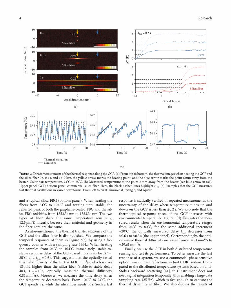
To investigate the thermal conduction enhancement,we heat a point on the GCF and on a section of silica fibersimultaneously in a vacuum, and we detect the thermalresponse by using a thermal imager. Figure 2(a) mapsthe images measured at different time delays; here, boththe GCF and the silica fiber are fixed in an insulationchamber with controlled macroscopic temperature 24°C,while the heater probe in 0.1mm size offers stable temper-ature 25°C (yellow arrow). The comparisons clearly showthat the spread of the temperature field along the GCF isfaster than the commercial silica fiber: when time delayis 0.1 s, the bright region of GCF (silica fiber) is ≈1.5mm(≈0.3mm), and when time delay is 1 s, the bright regionof GCF (silica fiber) is >10mm (≈2mm). In more detail,we record the temperature dynamics at the point 6mmaway from the heater (blue arrow); Figure 2(b) plots themeasured traces. In the measurement, the power of theheater is constant (2W) for each case, providing constanttemperatures. When temperature increases by 1°C, 2°C,and 3°C for transfer distance L = 6mm, the time requiredfor half of the maximum temperature rise t1/2 of GCF is0.2 s, while t1/2 of a silica fiber is 6 s. Referring to the tem-perature distribution model [35, 36], the thermal diffusiv-ity α = 1:38 L2/πt1/2, we estimate the diffusivity of theGCF in axial direction αGCF = 24:99 ± 1:2mm2/s, 30-foldhigher than the silica fiber without polymer coating(αsilica fiber = 0:83mm2/s). In measurements, systematicerror is ±0.01 s and ±10mK; this thermal diffusivity ofthe graphene nanosheet composite also meets the predic-tions in previous studies [37, 38]. Considering the rela-tionship of thermal diffusivity α and thermal conductivityK = αρCp, we estimate the thermal conductivity of theGCF KGCF ≈ 26:3Wm-1K-1 in the axial direction, about19-fold higher than the silica fiber (1.4Wm-1K-1 [39]);here, ρ = 1:5 g/cm3 is the density of the graphene coating,and Cp,graphene = 0:7 Jg-1 K-1 is the thermal capacity of thegraphene coating (Cp,silica = 0:68 Jg-1 K-1 [30]). Such rapid
2 Research
response enables the GCF to percept minor temperature fluc-tuations in dynamics; we show several examples in Figure 2(c),by adding thermal signals in sinusoidal (1Hz repetition,25.1°C to 25.5°C), triangle (1/6Hz repetition, 24.48°C to24.62°C), and square (1/10Hz repetition, 23.8°C to 24.4°C)waveform. The detected temperature at 20mm away can wellfollow the real temperature alterations.
In fiber sensing applications, the thermooptical responserelies on not only the time delay in the axial direction butalso the radial direction, from the fiber surface to the core.We simulate the thermal field diffusions in Section S2. Forcalibrating the practical thermooptical response, we write
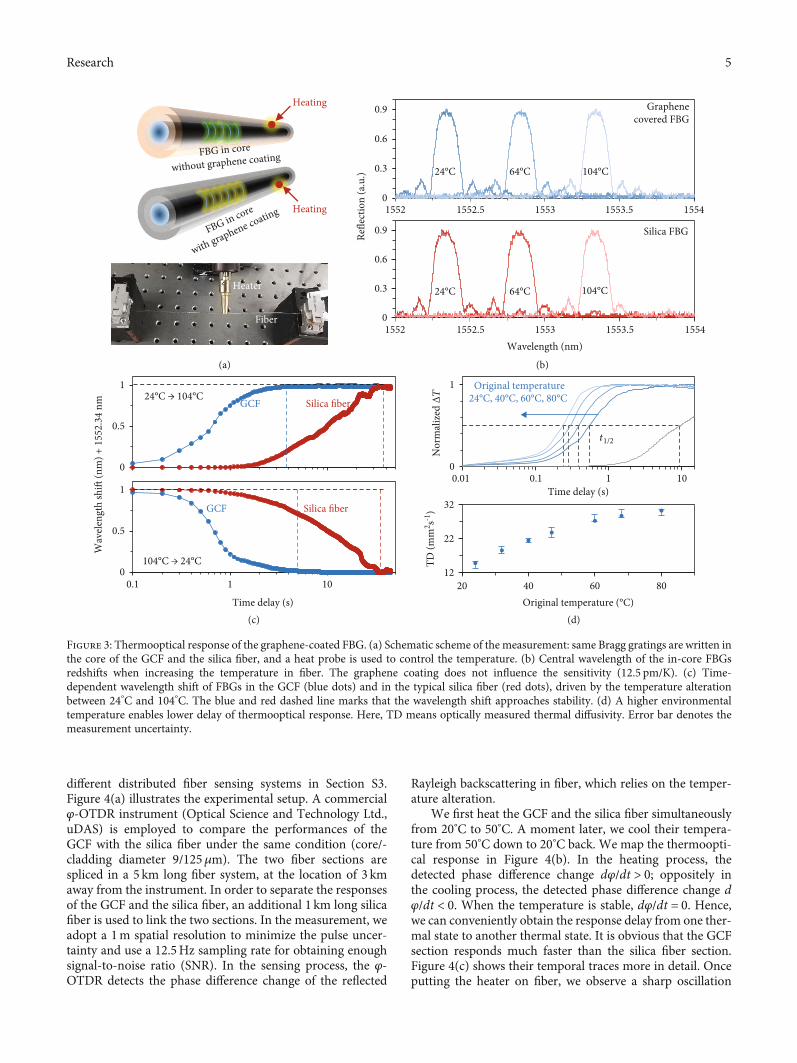
Bragg gratings in the fiber core of the GCF and use theGCF-based fiber Bragg grating (FBG) in temperature sens-ing (Figure 3(a)). In this measurement, the temporal sam-pling rate is >100Hz, which traces the thermooptical inhigh resolution. When temperature changes the refractiveindex n or the grating period Λ in fiber, the reflected inter-ference peak of a FBG shifts, meeting the relation λ = 2nΛ;here, λ is the Bragg wavelength [40]. In room temperature(24°C), Λ = 531:6nm, n = 1:46, λ = 1552:34nm. Then, weheat a point on the GCF, and the thermal transfer distancein the axial direction is 8mm. Figure 3(b) plots the reflec-tion spectra of the graphene-coated FBG (upper panel)
500 1000 1500 2000 2500 3000 3500
Fibe
r dra
win
g to
wer
(b)
Graphene coating
Thermal transfer
6 km
Graphene + Acrylate
Core Cladding
Graphene coating(a)
(c)
Silica
Silica fiber
GCF
500 𝜇m
(d)Raman shift (cm–1)
Inte
nsity
(a.u
. 100
0 a.u
. per
div
)G 2D
0 km
1 km
2 km
4 km
5 km
D
3 km
D+D
1 km
2 km
4 km
5 km
3 km
0 km
100 𝜇m
100 𝜇m 10 𝜇m
100 𝜇m
Figure 1: Conceptual design, industrial fabrication, and characterization of the GCF. (a) Schematic diagram of the GCF, 20 μm thickgraphene-acrylate hybrid is coated on the silica fiber. It can accelerate heat transfer along the axial direction, enhancing the opticalresponse of the fiber. (b) Industrial fabrication of the kilometers long GCF. Fiber drawing and graphene coating are finished in theassembly line automatically. (c) Microscopic pictures of the GCF; here, scale bars are marked inside. (d) Measured Raman spectra andside-view SEM pictures at different locations along the long GCF, verifying the consistent quality of the graphene and the uniformity ofthe coating.
3Research
and a typical silica FBG (bottom panel). When heating thefibers from 24°C to 104°C and waiting until stable, thereflected peak of both the graphene-coated FBG and the sil-ica FBG redshifts, from 1552.34 nm to 1553.34 nm. The twotypes of fiber share the same temperature sensitivity,12.5 pm/K linearly, because their material and geometry inthe fiber core are the same.
As aforementioned, the thermal transfer efficiency of theGCF and the silica fiber is distinguished. We compare thetemporal responses of them in Figure 3(c), by using a fre-quency counter with a sampling rate 1 kHz. When heatingthe samples from 24°C to 104°C immediately, stable-to-stable response delay of the GCF-based FBG is 4 s for ΔT =80°C, and t1/2 = 0:6 s. This suggests that the optically testedthermal diffusivity of the GCF is 14.81mm2/s, which is over18-fold higher than the silica fiber (stable-to-stable delay40 s, t1/2 = 10 s, optically measured thermal diffusivity0.81mm2/s). Moreover, we measure the time delay whenthe temperature decreases back. From 104°C to 24°C, theGCF spends 5 s, while the silica fiber needs 36 s. Such a fast
response is statically verified in repeated measurements, theuncertainty of the delay when temperature tunes up anddown on the GCF is less than ±0.2 s. We also note that thethermooptical response speed of the GCF increases withenvironmental temperature. Figure 3(d) illustrates the mea-sured result: when the environmental temperature rangesfrom 24°C to 80°C, for the same additional increment+20°C, the optically measured delay t1/2 decreases from≈0.6 s to ≈0.3 s (the upper panel). Correspondingly, the opti-cal sensed thermal diffusivity increases from ≈14.81mm2/s to≈29.61mm2/s.
Finally, we use the GCF in both distributed temperaturesensing and test its performance. To better measure the fastresponse of a system, we use a commercial phase-sensitiveoptical time domain reflectometry (φ-OTDR) system. Com-pared to the distributed temperature systems based on anti-Stokes backward scattering [41], this instrument does notneed signal integration temporally, thus enabling a large datasampling rate (25Hz), which is fast enough to capture thethermal dynamics in fiber. We also discuss the results of
–10
10
0
–100 6 12–6–12
10
0
–10
10
0
0 s
0.1 s
1 s
Radi
al d
irect
ion
(mm
)
(a)
GCF
Axial direction (mm)
Silica fiber
GCF
Silica fiber
GCF
Silica fiber0
1
2
3
0.1 1 10
0
1
2
3
GCF
(b)
Time delay (s)
25
25.2
25.4
25.6
0 5 10 15 2024.4
24.5
24.6
24.7
0 5 10 15 20
Thermal excitationMeasured
23.7
24.1
24.5
24.9
0 5 10 15 20
(c)
Time (s) Time (s) Time (s)
ΔT
(K)
Silica fiber
t1/2 = 0.2 s
t1/2 = 6 s
Figure 2: Direct measurement of the thermal response along the GCF. (a) From top to bottom, the thermal images when heating the GCF andthe silica fiber 0 s, 0.1 s, and 1 s. Here, the yellow arrow marks the heating point, and the blue arrow marks the point 6mm away from theheater. Color bar: temperature, 24°C to 25°C. (b) Measured temperature at the point 6mm away from the heater (see blue arrow in (a)).Upper panel: GCF; bottom panel: commercial silica fiber. Here, the black dashed lines highlight t1/2. (c) Examples that the GCF measuresfast thermal oscillations in varied waveforms. From left to right: sinusoidal, triangle, and square.
4 Research
different distributed fiber sensing systems in Section S3.Figure 4(a) illustrates the experimental setup. A commercialφ-OTDR instrument (Optical Science and Technology Ltd.,uDAS) is employed to compare the performances of theGCF with the silica fiber under the same condition (core/-cladding diameter 9/125μm). The two fiber sections arespliced in a 5 km long fiber system, at the location of 3 kmaway from the instrument. In order to separate the responsesof the GCF and the silica fiber, an additional 1 km long silicafiber is used to link the two sections. In the measurement, weadopt a 1m spatial resolution to minimize the pulse uncer-tainty and use a 12.5Hz sampling rate for obtaining enoughsignal-to-noise ratio (SNR). In the sensing process, the φ-OTDR detects the phase difference change of the reflected
Rayleigh backscattering in fiber, which relies on the temper-ature alteration.
We first heat the GCF and the silica fiber simultaneouslyfrom 20°C to 50°C. A moment later, we cool their tempera-ture from 50°C down to 20°C back. We map the thermoopti-cal response in Figure 4(b). In the heating process, thedetected phase difference change dφ/dt > 0; oppositely inthe cooling process, the detected phase difference change dφ/dt < 0. When the temperature is stable, dφ/dt = 0. Hence,we can conveniently obtain the response delay from one ther-mal state to another thermal state. It is obvious that the GCFsection responds much faster than the silica fiber section.Figure 4(c) shows their temporal traces more in detail. Onceputting the heater on fiber, we observe a sharp oscillation
0
0.5
1
0.1 1 10
0
0.3
0.6
0.9
1552 1552.5 1553 1553.5 1554
(a) (b)
Heating
Heating
Heater
Fiber
Graphenecovered FBG
Silica FBGRefle
ctio
n (a
.u.)
Wavelength (nm)
0
0.5
1
(c)
Wav
elen
gth
shift
(nm
) + 1
552.
34 n
m
Time delay (s)
GCF Silica fiber
(d)
12
22
32
20 40 60 80
GCF Silica fiber
Nor
mal
ized
ΔT
Original temperature
t1/2TD
(mm
2 s-1)
Time delay (s)
0
1
0.01 0.1 1 10
0
0.3
0.6
0.9
1552
FBG in core
with graphene coating
FBG in core
without graphene coating
1552.5 1553 1553.5 1554
Figure 3: Thermooptical response of the graphene-coated FBG. (a) Schematic scheme of the measurement: same Bragg gratings are written inthe core of the GCF and the silica fiber, and a heat probe is used to control the temperature. (b) Central wavelength of the in-core FBGsredshifts when increasing the temperature in fiber. The graphene coating does not influence the sensitivity (12.5 pm/K). (c) Time-dependent wavelength shift of FBGs in the GCF (blue dots) and in the typical silica fiber (red dots), driven by the temperature alterationbetween 24°C and 104°C. The blue and red dashed line marks that the wavelength shift approaches stability. (d) A higher environmentaltemperature enables lower delay of thermooptical response. Here, TD means optically measured thermal diffusivity. Error bar denotes themeasurement uncertainty.
5Research
immediately. This is a mechanical fluctuation signal inducedby the fiber heater. Its temporal duration is <0.02 s. Mean-while, the fibers begin to feel the heat. In the GCF section,benefiting from its fast thermal conduction, the temperatureof the whole section changes rapidly from 20°C to 50°C (sta-ble to stable); the optical measured delay of the GCF sectionis ≈0.8 s. In comparison, the silica fiber responds slowly(temporal delay ≈ 12 s). Such fast thermal response of the
GCF is repeatedly measured as shown in Figure 4(d). We alsonote that the graphene on-fiber coating does not deterioratethe sensitivity, because the graphene does not influence thelight propagating in the fiber core. By periodically heatingand cooling the GCF, we plot its phase difference responsein Figure 4(c). In this measurement, data error is <5%.Figure 4(e) summarizes the fast sensing performance. Forthe fast distributed sensing system for temperature tracing,
DASRayleigh
back scattering
(a)
Spatial resolution 1 m Spatial resolution 1 m
Heating point
GCF Silica fiber1km distance
0 1 2 3 4 50
20Tim
e (s)
(b)
Distance (km), resolution 1 m
–30 30 GCF Silica fiber40
0 4 8 12 16 20 24 28 32 36 40 44 48
(c)
Silica fiber
GCF
11 12 13 14 15
GCFSilica fiber
Mec
hani
cal
fluct
uatio
nZoom in
0 100 200 300 400 500 600
Time delay (s) Time delay (s)
Heating
Cooling
d𝜑/dt
(10
rads
/div
)
d𝜑/dt (rad)
d𝜑/dt
(10
rads
/div
)
(d)
0.01
0.1
1
10
100
Silica fiber GCFFluctuationThermal
Resp
onse
del
ay (s
)
(e)
Time (s)
Figure 4: Performance of the GCF in distributed temperature sensing based on φ-OTDR. (a) Experimental setup; here, a commercial φ-OTDR instrument provides the pump laser and detects the reflected Rayleigh backscattering. A section of GCF is linked in a 5 km longfiber system, and we heat two separate points simultaneously. Spatial resolution of this φ-OTDR is 1m. (b) Measured temperaturedynamics of 1m long GCF (at the 3 km location) and 1m long silica fiber (at the 4 km location), respectively. (c) Temporal response ofthe GCF (top panel) and the silica fiber (bottom panel) from 0 s to 50 s. (d) Fast sensing performance of the GCF by repeatedmeasurements. (e) Comparison of the fast sensing performance between the GCF and the silica fiber.
6 Research
the graphene-coated fiber can respond 15 times faster thanthe silica fiber. We also note that the spatial resolution ofthe sensing system is determined by the signal modulation;hence, using the GCF would not improve its positioningaccuracy. Besides the φ-OTDR, we also demonstrate thatour GCF responds faster than silica fiber in the distributedtemperature sensing (DTS) system based on Raman back-scattering (see extended data in Section S3).
3. Discussion
In a nutshell, we report the kilometers long GCF, which couldbe mass-produced, via coating graphene nanosheets on thesurface of silica fibers industrially. Such GCF demonstratesfast thermal response, with thermal diffusivity ≈ 24:99mm2/s in the axial direction, 30-fold higher than conven-tional silica fiber. Leveraging this new fiber can enable detect-ing acceleration over 18-fold improvement for the FBGtemperature sensor at one point, or 15-fold improvementfor long-distance distributed fiber sensing system. Such fastresponse also demonstrates high reliability and robustnessin repeated measurements. This work builds a bridge forthe industrial combination of graphene and fiber optics,which offers not only inspiration for the combination ofother 2D materials and optical structures but also a novelplatform for high-performance optic-fiber temperature sens-ing, which may bring unpredicted evolution for applicationssuch as deep-earth/deep-sea exploration, remote safety mon-itoring, and fire warning.
4. Materials and Methods
4.1. Fabrication and Characterization of the GCF. First, wemixed and stirred the graphene dispersion and the acrylate(graphene 30wt%). This hybrid is sprayable by using anindustrial fiber coater, under 120 kPa pressure. Optical fiberswere fabricated directly in the drawing tower. Then, we con-trolled the spraying speed to ensure the coating thickness20μm. After surface coating, the graphene-acrylate film wasexposed to UV light for full solidification. This implementa-tion replaced the conventional polymer coating of a fiber tographene-based material. We characterized the quality ofthe graphene coating by using microscopy, electric method,and Raman spectroscopy. The graphene nanosheets on-fiber are distributed tightly, enabling a typical electrical resis-tance 6 kΩ/mm.
4.2. Experimental Measurements. (1) Direct measurement ofthermal diffusivity of the GCF: A temperature-controlledprobe (TEC) was applied to heat a point on the fiber. Theheated short fiber sections were pictured by using a lens cal-ibrated thermoimager (Flir 655c), with temperature resolu-tion 0.1K, and spatial resolution 0.1mm. (2) Opticalmeasurement by using FBGs: We prepared FBG by usingUV writing technique, and then, we coated the graphene-acrylate on the FBG. The FBG was measured by using anoptoelectronic demodulator (FAZ Technology I4G), with asampling rate 1 kHz and frequency resolution 0.1 pm. (3)Measurement based on the φ-OTDR: The temperature distri-
bution along the GCF/silica fiber was measured throughemploying a φ-OTDR (Optical Science and TechnologyLtd., uDAS), with spatial resolution 1m and maximum sam-pling rate 250Hz.
Conflicts of Interest
The authors declare no competing financial interests.
Authors’ Contributions
B.Y. and Y.R. led this work. Y.G., B.H., J.D., and N.A. builtthe setup and measured the fibers and sensing systems.H.G. and W.R. led the fabrication and optimization of thegraphene material. S.C. B.H., Y.G., and D.J. led the fabrica-tion of the graphene-coated fibers. B.Y., Y.L., B.H., andC.Q. finished the theoretical analysis. All the authors dis-cussed and analyzed the results. B.Y., B.H., Y.G., Y.L., W.R.,and Y.R. prepared the manuscript. Yiyong Guo, Bing Han,and Junting Du contributed equally to this work.
Acknowledgments
We thank the discussion and support from Prof. ZinanWangand Dr. Teng Tan from the UESTC. The authors acknowl-edge support from the National Science Foundation of China(61705032 and 61975025), the 111 project (B14039), and theUESTC-ZTT joint laboratory project (H04W180463).
Supplementary Materials
Section S1: material preparation and characterization.Section S2: experimental setups and extended discussionsfor FBG testing. Section S3: experimental setup and extendeddiscussions for distributed fiber temperature testing. FigureS1: preparation of the graphene nanosheets in industry.Figure S2: electrical property of the GCF. Figure S3: setups.Figure S4: simulated temperature field diffusions. Figure S5:measured spectral shift trace of the graphene-coated FBG.Figure S6: schematic diagrams of the distributed fiber sensingsystems. Figure S7: performance of the GCF for temperaturesensing in Raman scattering-based DTS. Table S1: propertiesof the graphene nanosheets. Table S2: comparison of differ-ent GCF fabrication schemes. Table S3: sensing performancecomparison of the graphene-coated and gold-coated fibers.References (28, 42–46). (Supplementary Materials)
References
[1] C. K. Kao, “Nobel lecture: sand from centuries past: sendfuture voices fast,” Reviews of Modern Physics, vol. 82, no. 3,pp. 2299–2303, 2010.
[2] M. A. Soto, J. A. Ramírez, and L. Thévenaz, “Intensifying theresponse of distributed optical fibre sensors using 2D and 3Dimage restoration,” Nature Communications, vol. 7, pp. 1–11,2016.
[3] A. Zadok, Y. Antman, N. Primerov, A. Denisov, J. Sancho, andL. Thevenaz, “Random-access distributed fiber sensing,” Laser& Photonics Reviews, vol. 6, pp. 1–5, 2012.
[4] N. J. Lindsey, T. Craig Dawe, and J. B. Ajo-Franklin, “Illumi-nating seafloor faults and ocean dynamics with dark fiber dis-tributed acoustic sensing,” Science, vol. 366, pp. 1103–1107,2019.
[5] T. Yamate, G. Fujisawa, and T. Ikegami, “Optical sensors forthe exploration of oil and gas,” Journal of Lightwave Technol-ogy, vol. 35, no. 16, pp. 3538–3545, 2017.
[6] Z. Wang, B. Zhang, J. Xiong et al., “Distributed acoustic sens-ing based on pulse-coding phase-sensitive OTDR,” IEEE Inter-net of Things Journal, vol. 6, no. 4, pp. 6117–6124, 2019.
[7] A. H. Castro Neto, F. Guinea, N. M. R. Peres, K. S. Novoselov,and A. K. Geim, “The electronic properties of graphene,”Reviews of Modern Physics, vol. 81, no. 1, pp. 109–162,2009.
[8] P. Avouris, “Graphene: electronic and photonic propertiesand devices,” Nano Letters, vol. 10, no. 11, pp. 4285–4294,2010.
[9] B. Yao, Y. Liu, S. W. Huang et al., “Broadband gate-tunableterahertz plasmons in graphene heterostructures,” NaturePhotonics, vol. 12, no. 1, pp. 22–28, 2018.
[10] B. Yao, S. W. Huang, Y. Liu et al., “Gate-tunable frequencycombs in graphene-nitride microresonators,” Nature,vol. 558, no. 7710, pp. 410–414, 2018.
[11] A. Zandiatashbar, G. H. Lee, S. J. An et al., “Effect of defects onthe intrinsic strength and stiffness of graphene,” Nature Com-munications, vol. 5, pp. 1–9, 2014.
[12] S. Ghosh, I. Calizo, D. Teweldebrhan et al., “Extremely highthermal conductivity of graphene: prospects for thermal man-agement applications in nanoelectronic circuits,” AppliedPhysics Letters, vol. 92, pp. 2008–2011, 2008.
[13] G. Xin, T. Yao, H. Sun et al., “Highly thermally conductive andmechanically strong graphene fibers,” Science, vol. 349,pp. 1083–1087, 2015.
[14] E. Pop, V. Varshney, and A. K. Roy, “Thermal properties ofgraphene: Fundamentals and applications,” MRS Bulletin,vol. 37, pp. 1273–1281, 2012.
[15] T. Tan, X. Jiang, C. Wang, B. Yao, and H. Zhang, “2D materialoptoelectronics for information functional device applications:status and challenges,” Advancement of Science, vol. 7,p. 2000058, 2020.
[16] C. Qin, K. Jia, Q. Li et al., “Electrically controllable laser fre-quency combs in graphene-fibre microresonators,” Light: Sci-ence & Applications, vol. 9, no. 1, p. 185, 2020.
[17] A. Martinez and Z. Sun, “Nanotube and graphene saturableabsorbers for fibre lasers,” Nature Photonics, vol. 7, no. 11,pp. 842–845, 2013.
[18] Q. Bao, H. Zhang, Y. Wang et al., “Atomic-layer graphene as asaturable absorber for ultrafast pulsed lasers,” Advanced Func-tional Materials, vol. 19, no. 19, pp. 3077–3083, 2009.
[19] Z. Sun, T. Hasan, F. Torrisi et al., “Graphene mode-lockedultrafast laser,” ACS Nano, vol. 4, no. 2, pp. 803–810, 2010.
[20] Z. Sun, A. Martinez, and F. Wang, “Optical modulators with2D layered materials,” Nature Photonics, vol. 10, no. 4,pp. 227–238, 2016.
[21] W. Li, B. Chen, C. Meng et al., “Ultrafast all-optical graphenemodulator,” Nano Letters, vol. 14, no. 2, pp. 955–959, 2014.
[22] J.-H. Chen, B.-C. Zheng, G.-H. Shao, S.-J. Ge, F. Xu, and Y.-Q. Lu, “An all-optical modulator based on a stereo graphene-microfiber structure,” Light: Science & Applications, vol. 4,no. 12, pp. e360–e360, 2015.
[23] Y. Cheng, R. Wang, J. Sun, and L. Gao, “A stretchable andhighly sensitive graphene-based fiber for sensing tensile strain,bending, and torsion,” Advanced Materials, vol. 27, no. 45,pp. 7365–7371, 2015.
[24] Z. Cao, B. Yao, C. Qin et al., “Biochemical sensing in graphene-enhanced microfiber resonators with individual molecule sen-sitivity and selectivity,” Light: Science & Applications, vol. 8,pp. 1–10, 2019.
[25] B. Yao, C. Yu, Y. Wu et al., “Graphene-enhanced brillouinoptomechanical microresonator for ultrasensitive gas detec-tion,” Nano Letters, vol. 17, no. 8, pp. 4996–5002, 2017.
[26] N. An, T. Tan, Z. Peng et al., “Electrically tunable four-wave-mixing in graphene heterogeneous fiber for individual gasmolecule detection,” Nano Letters, vol. 20, no. 9, pp. 6473–6480, 2020.
[27] K. Chen, X. Zhou, X. Cheng et al., “Graphene photonic crystalfibre with strong and tunable light-matter interaction,” NaturePhotonics, vol. 13, no. 11, pp. 754–759, 2019.
[28] W. Ren and H. M. Cheng, “The global growth of graphene,”Nature Nanotechnology, vol. 9, no. 10, pp. 726–730, 2014.
[29] D. Chardon and S. J. Huard, “Thermal diffusivity of opticalfibers measured by photoacoustics,” Applied Physics Letters,vol. 41, no. 4, pp. 341-342, 1982.
[30] A. A. Balandin, “Thermal properties of graphene and nano-structured carbon materials,” Nature Materials, vol. 10, no. 8,pp. 569–581, 2011.
[31] S. Chen, Q. Wu, C. Mishra et al., “Thermal conductivity of iso-topically modified graphene,” Nature Materials, vol. 11, no. 3,pp. 203–207, 2012.
[32] X. Xu, L. F. C. Pereira, Y. Wang et al., “Length-dependent ther-mal conductivity in suspended single-layer graphene,” NatureCommunications, vol. 5, pp. 1–6, 2014.
[33] J. Bin Wu, M. L. Lin, X. Cong, H. N. Liu, and P. H. Tan,“Raman spectroscopy of graphene-based materials and itsapplications in related devices,” Chemical Society Reviews,vol. 47, pp. 1822–1873, 2018.
[34] A. C. Ferrari, “Raman spectroscopy of graphene and graphite:disorder, electron-phonon coupling, doping and nonadiabaticeffects,” Solid State Communications, vol. 143, no. 1-2, pp. 47–57, 2007.
[35] H. Capacity, “Flash method of determining thermal diffusiv-ity,” Encyclopedia of Thermal Stresses, pp. 1683–1683, 2014.
[36] K. A. Borup, J. De Boor, H. Wang et al., “Measuring thermo-electric transport properties of materials,” Energy & Environ-mental Science, vol. 8, no. 2, pp. 423–435, 2015.
[37] M. Gresil, Z. Wang, Q. A. Poutrel, and C. Soutis, “Thermal dif-fusivity mapping of graphene based polymer nanocompos-ites,” Scientific Reports, vol. 7, pp. 1–10, 2017.
[38] M. Potenza, A. Cataldo, G. Bovesecchi, S. Corasaniti, P. Coppa,and S. Bellucci, “Graphene nanoplatelets: thermal diffusivityand thermal conductivity by the flash method,” AIP Advances,vol. 7, no. 7, article 075214, 2017.
[39] D. R. Lide andW. M. Haynes, CRC handbook of chemistry andphysics, CRC Press, 1995.
[40] Y. Wu, B. Yao, A. Zhang et al., “Graphene-coated microfiberBragg grating for high-sensitivity gas sensing,” Optics Letters,vol. 39, no. 5, pp. 1235–1237, 2014.
[41] J. P. Dakin, D. J. Pratt, G. W. Bibby, and J. N. Ross, “Distrib-uted optical fibre Raman temperature sensor using a semicon-ductor light source and detector,” Electronics Letters, vol. 21,no. 13, p. 569, 1985.
8 Research
[42] I. Meric, M. Y. Han, A. F. Young, B. Ozyilmaz, P. Kim, andK. L. Shepard, “Current saturation in zero-bandgap, top-gated graphene field-effect transistors,” Nature Nanotechnol-ogy, vol. 3, no. 11, pp. 654–659, 2008.
[43] F. Schwierz, “Graphene transistors,” Nature Nanotechnology,vol. 5, no. 7, pp. 487–496, 2010.
[44] A. Masoudi, M. Belal, and T. P. Newson, “A distributed opticalfibre dynamic strain sensor based on phase-OTDR,”Measure-ment Science and Technology, vol. 24, no. 8, article 085204,2013.
[45] R. Sutherland, J. Townend, V. Toy et al., “Extreme hydrother-mal conditions at an active plate-bounding fault,” Nature,vol. 546, pp. 137–140, 2017.
[46] J. Li, Q. Zhang, T. Yu et al., “R-DTS with heat transfer func-tional model for perceiving the surrounding temperature,”IEEE Sensors Journal, vol. 20, no. 2, pp. 816–822, 2020.