27
Kinematics of Machines SUB CODE: 10ME44
Kinematics of Machines
SUB CODE: 10ME44
Content
Basic Definitions Link or element
kinematic pairs
Degrees of freedom
Grubler’s criterion
Kinematic chain
Mechanism, Structure
Mobility of Mechanism
Inversion
Machine
Kinematic Chains and Inversions
Inversions of Four bar chain;
Single slider crank chain and
Double slider crank chain
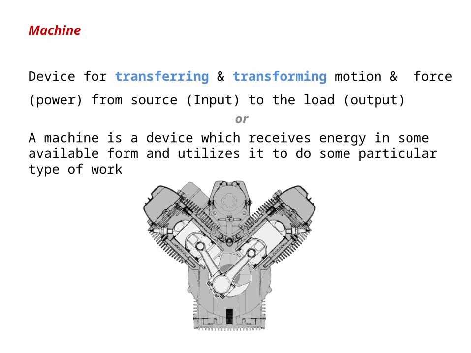
Machine
Device for transferring & transforming motion & force (power) from source
(Input) to the load (output)or
A machine is a device which receives energy in some available form and utilizes it to do some particular type of work
Sub-divisions of Theory of Machines
1. Kinematics. which deals with the relative motion between the various parts of the machines.
2. Dynamics. which deals with the forces and their effects, while actingupon the machine parts in motion.
3. Kinetics. which deals with the inertia forces which arise from the combined effect of the mass and motion of the machine parts.
4. Statics. which deals with the forces and their effects while the machine parts are at rest.
The mass of the parts is assumed to be negligible.
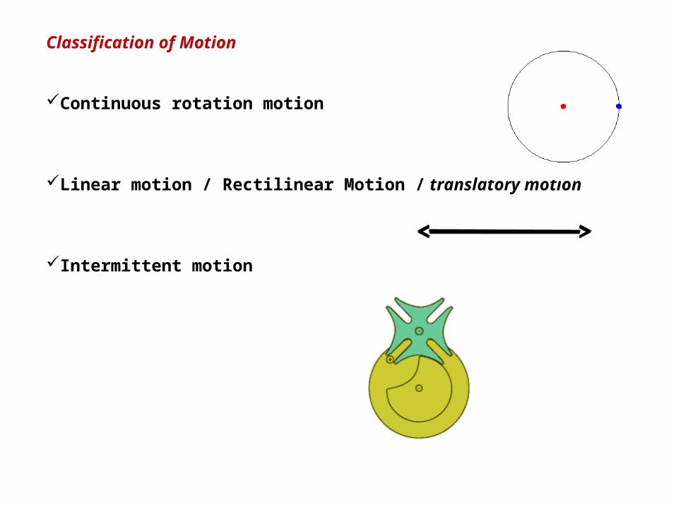
Classification of Motion
Continuous rotation motion
Linear motion / Rectilinear Motion / translatory motion
Intermittent motion

For the study of kinematics the machine may be referred as Mechanism, which
is a combination of interconnected rigid bodies capable of relative motion
Each part of a machine, which moves relative to some other part, is known as a kinematic link (or simply link) or element
Kinematic Link or Element
Reciprocating steam engine
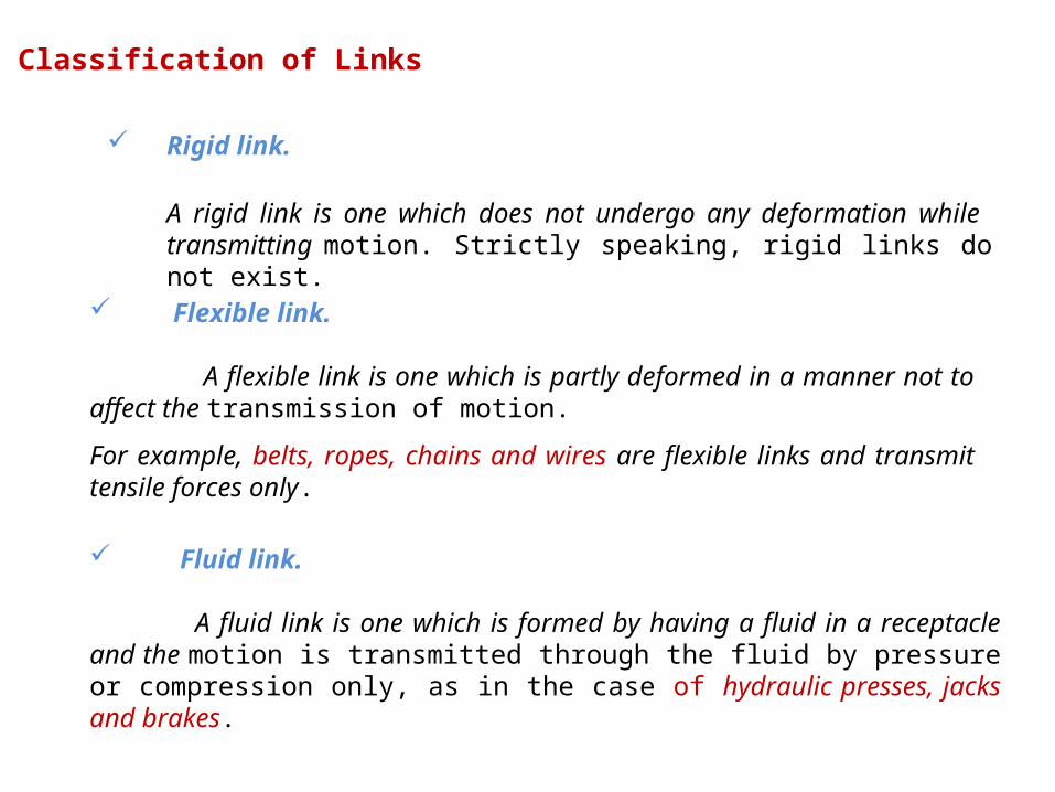
Classification of Links
Rigid link.
A rigid link is one which does not undergo any deformation while transmitting motion. Strictly speaking, rigid links do not exist.
Flexible link.
A flexible link is one which is partly deformed in a manner not to affect the transmission of motion.
For example, belts, ropes, chains and wires are flexible links and transmit tensile forces only.
Fluid link.
A fluid link is one which is formed by having a fluid in a receptacle and the motion is transmitted through the fluid by pressure or compression only, as in the case of hydraulic presses, jacks and brakes.

Binary link : which is connected to other links at two points
Ternary link: which is connected to other links at three points
Quaternary link: which is connected to other links at four points
Classification of Links
Structure
It is an assemblage of a number of resistant bodies (known as members)
having no relative motion between them and meant for carrying loads having
straining action.
A railway bridge, a roof truss, machine frames etc., are the examples of a structure.
Difference Between a Machine and a Structure
The parts of a machine move relative to one another, whereas the members of a structure do not move relative to one another
A machine transforms the available energy into some useful work, whereas in a structure no energy is transformed into useful work
The links of a machine may transmit both power and motion, while the members of a structure transmit forces only.
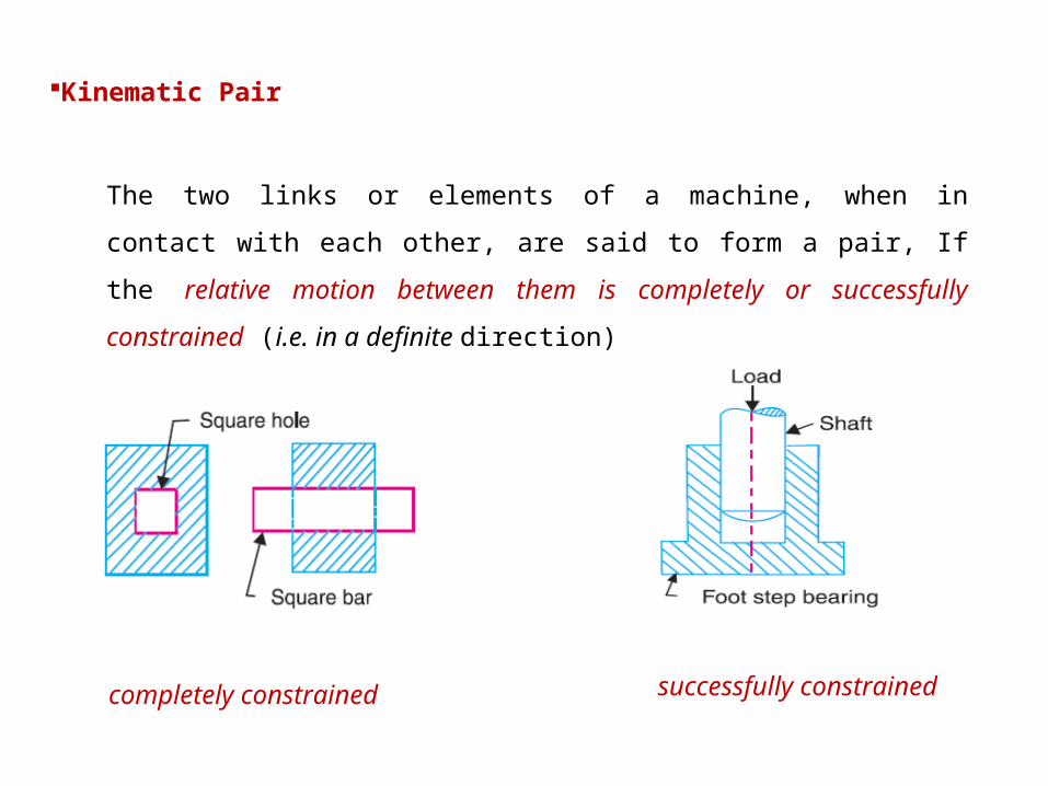
Kinematic Pair
The two links or elements of a machine, when in contact with each other, are
said to form a pair, If the relative motion between them is completely or
successfully constrained (i.e. in a definite direction)
successfully constrained completely constrained
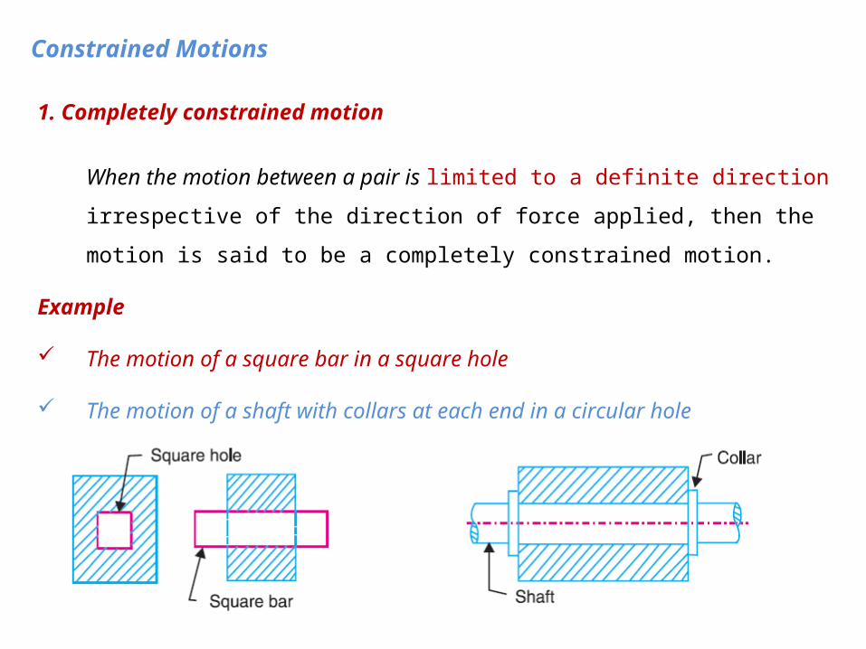
1. Completely constrained motion
When the motion between a pair is limited to a definite direction irrespective of the
direction of force applied, then the motion is said to be a completely constrained
motion.
Example
The motion of a square bar in a square hole
The motion of a shaft with collars at each end in a circular hole
Constrained Motions

2. Incompletely constrained motion
When the motion between a pair can take place in more than one direction
E.g.: A circular bar or shaft in a circular hole
it may either rotate or slide in a hole. These both motions have no relationship with the other.
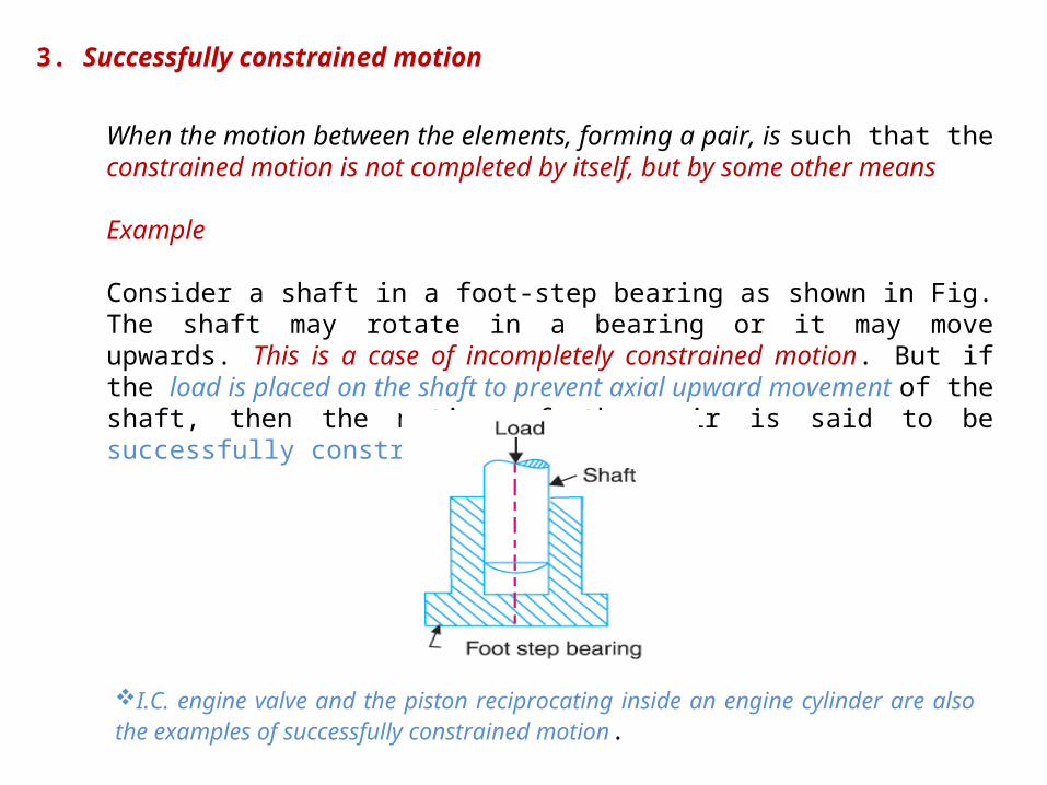
3. Successfully constrained motion
When the motion between the elements, forming a pair, is such that the constrained motion is not completed by itself, but by some other means
Example
Consider a shaft in a foot-step bearing as shown in Fig. The shaft may rotate in a bearing or it may move upwards. This is a case of incompletely constrained motion. But if the load is placed on the shaft to prevent axial upward movement of the shaft, then the motion of the pair is said to be successfully constrained motion.
I.C. engine valve and the piston reciprocating inside an engine cylinder are also the examples of successfully constrained motion.
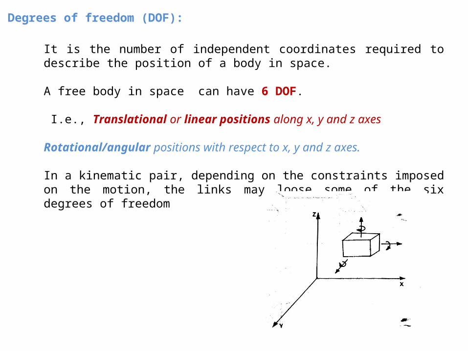
Degrees of freedom (DOF):
It is the number of independent coordinates required to describe the position of a body in space.
A free body in space can have 6 DOF.
I.e., Translational or linear positions along x, y and z axes
Rotational/angular positions with respect to x, y and z axes.
In a kinematic pair, depending on the constraints imposed on the motion, the links may loose some of the six degrees of freedom
Classification of Kinematic Pairs
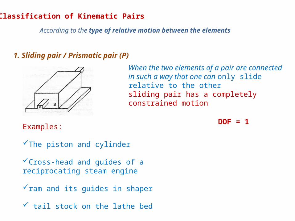
1. Sliding pair / Prismatic pair (P)
When the two elements of a pair are connected in such a way that one can only slide relative to the othersliding pair has a completely constrained motion
Examples:
The piston and cylinder
Cross-head and guides of a reciprocating steam engine
ram and its guides in shaper
tail stock on the lathe bed
According to the type of relative motion between the elements
DOF = 1

2. Turning Pair / Revolute Pair (R)
When the two elements of a pair are connected in such a way that one can only turn or revolve about a fixed axis of another link
Examples Lathe spindle supported in head stock cycle wheels turning over their axles
3. Spherical pair (S) When the two elements of a pair are connected in such a way that one element (with spherical shape) turns or swivels about the other fixed element
Examples
The ball and socket joint
Attachment of a car mirror
pen stand
DOF = 1
DOF = 3

4. Screw pair When the two elements of a pair are connected in such a
way that one element can turn about the other by screw
threads.
Examples
The lead screw of a lathe with nut
bolt with a nut
5. Cylindrical pair
If the relative motion between the pairing
elements is the combination of turning and
sliding, then it is called as cylindrical pair.
DOF = 2
DOF = 1
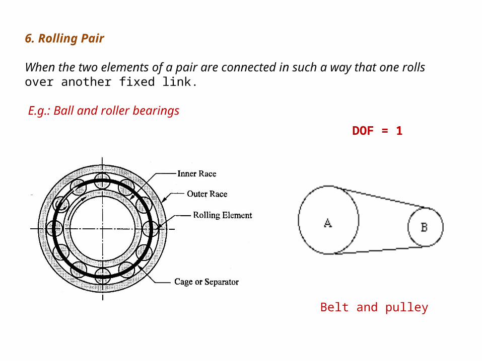
6. Rolling Pair
When the two elements of a pair are connected in such a way that one rollsover another fixed link.
E.g.: Ball and roller bearings
Belt and pulley
DOF = 1
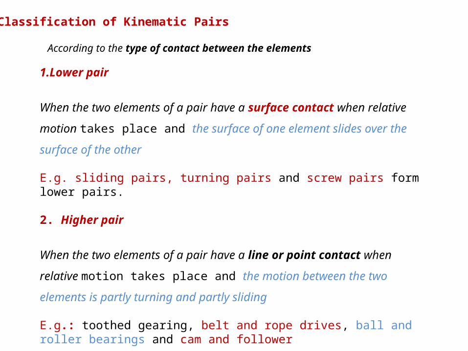
According to the type of contact between the elements
Classification of Kinematic Pairs
1.Lower pair
When the two elements of a pair have a surface contact when relative
motion takes place and the surface of one element slides over the surface
of the other
E.g. sliding pairs, turning pairs and screw pairs form lower pairs.
2. Higher pair
When the two elements of a pair have a line or point contact when
relative motion takes place and the motion between the two elements is
partly turning and partly sliding
E.g.: toothed gearing, belt and rope drives, ball and roller bearings and cam and follower

Classification of Kinematic Pairs
According to the type of closure
1. Self closed pair:
When the two elements of a pair are connected together mechanically in
such a way that only required relative motion occurs, it is then known as self
closed pair.
E.g. lower pairs are self closed pair.
Closed pair

2. Force - closed pair.
When the two elements of a pair are not connected mechanically but
are kept in contact by the action of external forces, the pair is said to be
a force-closed pair.
E.g.: The cam and follower it is kept in contact by the forces exerted by spring and gravity.
Force closed pair (cam & follower)

Lower pair Higher pair Self closed pair Force - closed pair
sliding pairs
turning pairs
screw pairs
Rolling pair
Kinematic Pairs
Spherical pair
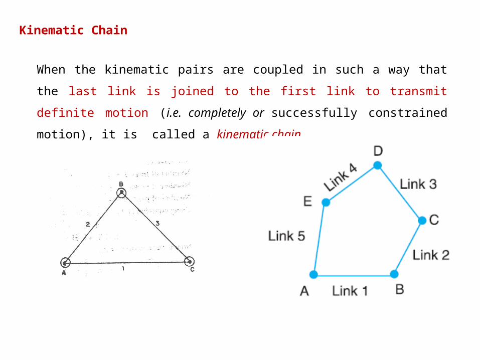
Kinematic Chain
When the kinematic pairs are coupled in such a way that the last link is joined to the
first link to transmit definite motion (i.e. completely or successfully constrained
motion), it is called a kinematic chain.
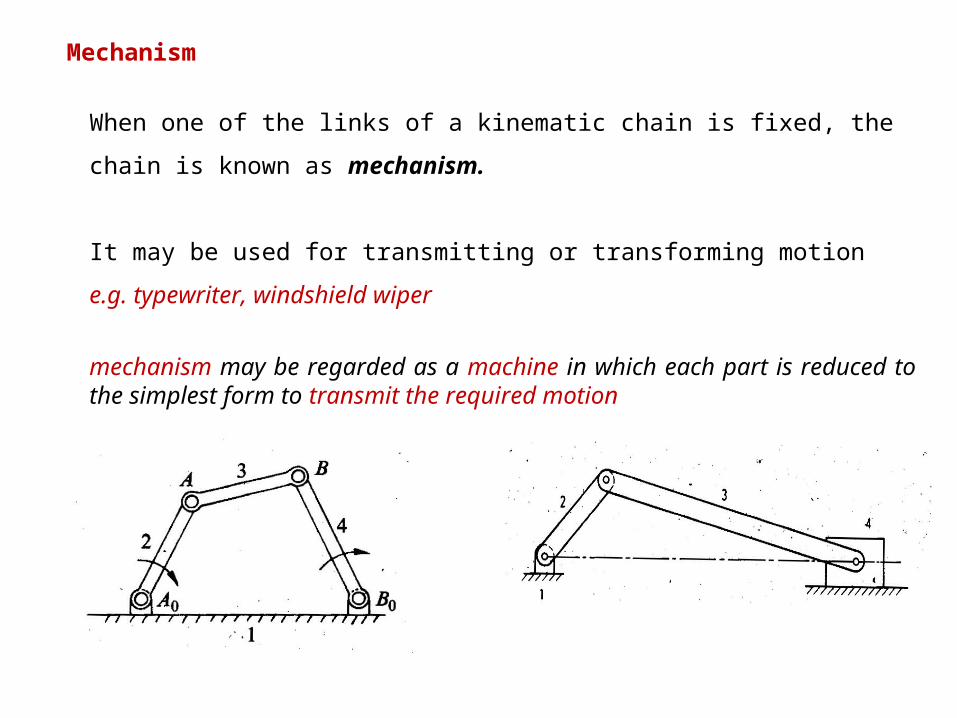
Mechanism
When one of the links of a kinematic chain is fixed, the chain is known as
mechanism.
It may be used for transmitting or transforming motion
e.g. typewriter, windshield wiper
mechanism may be regarded as a machine in which each part is reduced to the simplest form to transmit the required motion

Degrees of freedom/mobility of a mechanism
number of independent coordinates required to describe the
configuration or position of all the links of the mechanism, with
respect to the fixed link at any given instant.
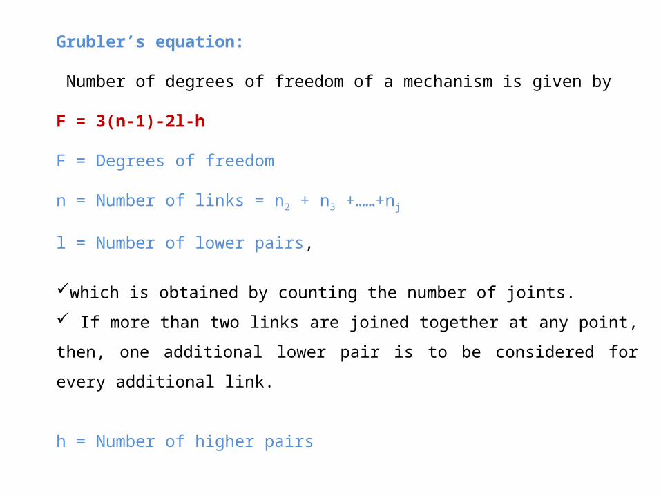
Grubler’s equation:
Number of degrees of freedom of a mechanism is given by F = 3(n-1)-2l-h
F = Degrees of freedom
n = Number of links = n2 + n3 +……+nj
l = Number of lower pairs,
which is obtained by counting the number of joints.
If more than two links are joined together at any point, then, one additional
lower pair is to be considered for every additional link.
h = Number of higher pairs
Inversion of Mechanism
A mechanism is one in which one of the links of a kinematic chain is fixed.
Different mechanisms can be obtained by fixing different links of the same
kinematic chain.


