KINETICS™ Seismic & Wind Design Manual Section A MASTER DOCUMENT PAGE 1 of 3 SECTION – A Toll Free (USA Only): 800-959-1229 RELEASED ON: 4/23/2014 International: 614-889-0480 FAX 614-889-0540 World Wide Web: www.kineticsnoise.com E-mail: [email protected]Dublin, Ohio, USA ∙ Cambridge, Ontario, Canada APPENDIX - TABLE OF CONTENTS Title Section Revision Record A-A Appendix (All Sections Title Section FIELD INSPECTION FORMS Inspection Preparation A1.1 Inspecting Distribution Systems A1.2 Inspecting Equipment A1.3 FREQUENTLY ASKED QUESTIONS A2.0 HOUSEKEEPING PAD DESIGN GUIDELINES A3.0 PIPE DATA TABLES A4.0 Standard Steel Pipe Data – English Units A4.1.1 Standard Steel Pipe Data – SI Units A4.1.2 PVC & CPVC Standard Pipe Data – English Units A4.2.1 PVC & CPVC Standard Pipe Data – SI Units A4.2.2 CPVC Fire Sprinkler Pipe Data – English Units A4.3.1 CPVC Fire Sprinkler Pipe Data – SI Units A4.3.2 Copper Pipe Data – English Units A4.4.1 Copper Pipe Data – SI Units A4.4.2
Transcript
KINETICS™ Seismic & Wind Design Manual Section A
MASTER DOCUMENT PAGE 1 of 3 SECTION – A Toll Free (USA Only): 800-959-1229 RELEASED ON: 4/23/2014 International: 614-889-0480 FAX 614-889-0540 World Wide Web: www.kineticsnoise.com E-mail: [email protected] Dublin, Ohio, USA ∙ Cambridge, Ontario, Canada
APPENDIX - TABLE OF CONTENTS
Title Section Revision Record A-A
Appendix (All Sections Title Section
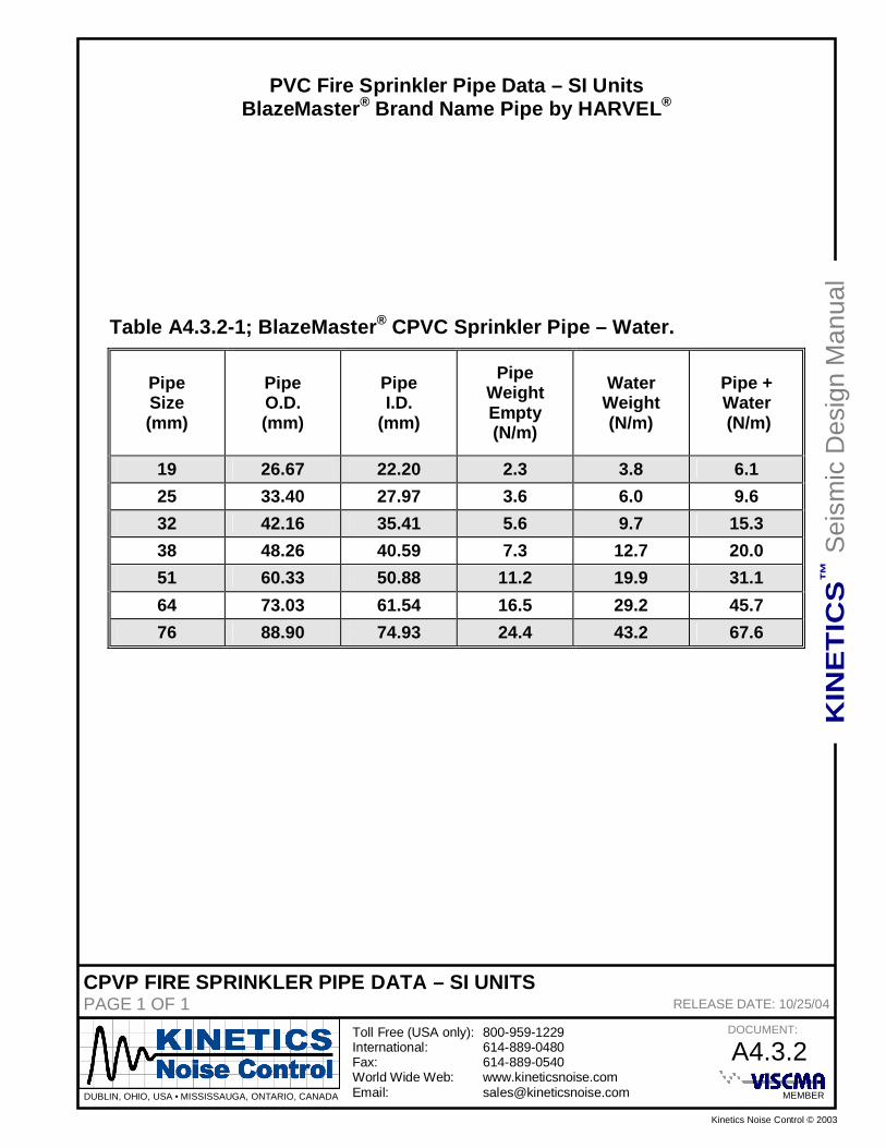
FIELD INSPECTION FORMS Inspection Preparation A1.1 Inspecting Distribution Systems A1.2 Inspecting Equipment A1.3 FREQUENTLY ASKED QUESTIONS A2.0 HOUSEKEEPING PAD DESIGN GUIDELINES A3.0 PIPE DATA TABLES A4.0 Standard Steel Pipe Data – English Units A4.1.1 Standard Steel Pipe Data – SI Units A4.1.2 PVC & CPVC Standard Pipe Data – English Units A4.2.1 PVC & CPVC Standard Pipe Data – SI Units A4.2.2 CPVC Fire Sprinkler Pipe Data – English Units A4.3.1 CPVC Fire Sprinkler Pipe Data – SI Units A4.3.2 Copper Pipe Data – English Units A4.4.1 Copper Pipe Data – SI Units A4.4.2
KINETICS™ Seismic & Wind Design Manual Section A
MASTER DOCUMENT PAGE 2 of 3 SECTION – A Toll Free (USA Only): 800-959-1229 RELEASED ON: 4/23/2014 International: 614-889-0480 FAX 614-889-0540 World Wide Web: www.kineticsnoise.com E-mail: [email protected] Dublin, Ohio, USA ∙ Cambridge, Ontario, Canada
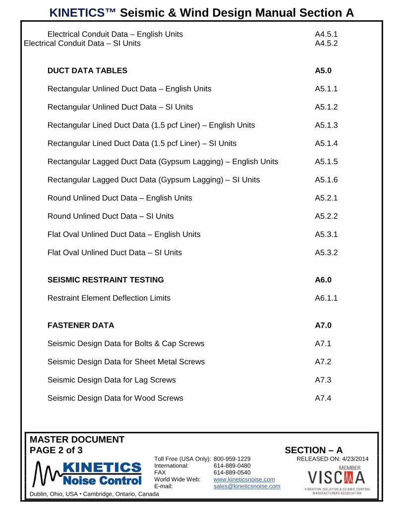
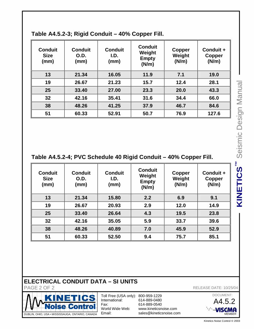
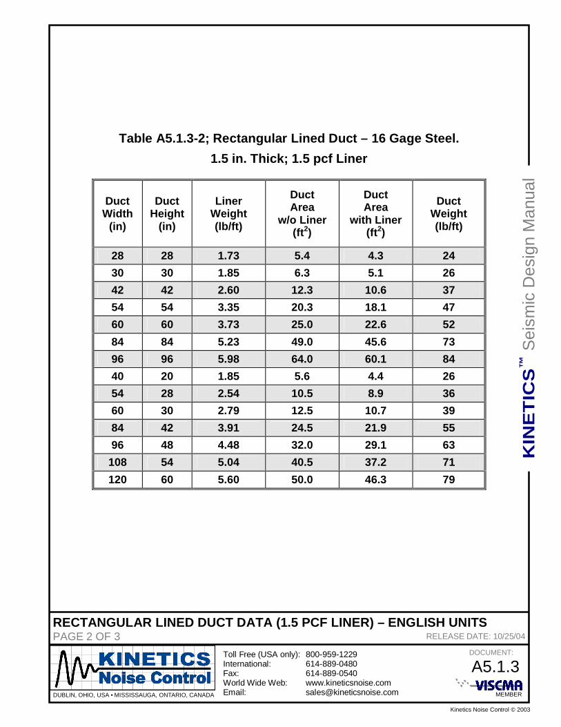
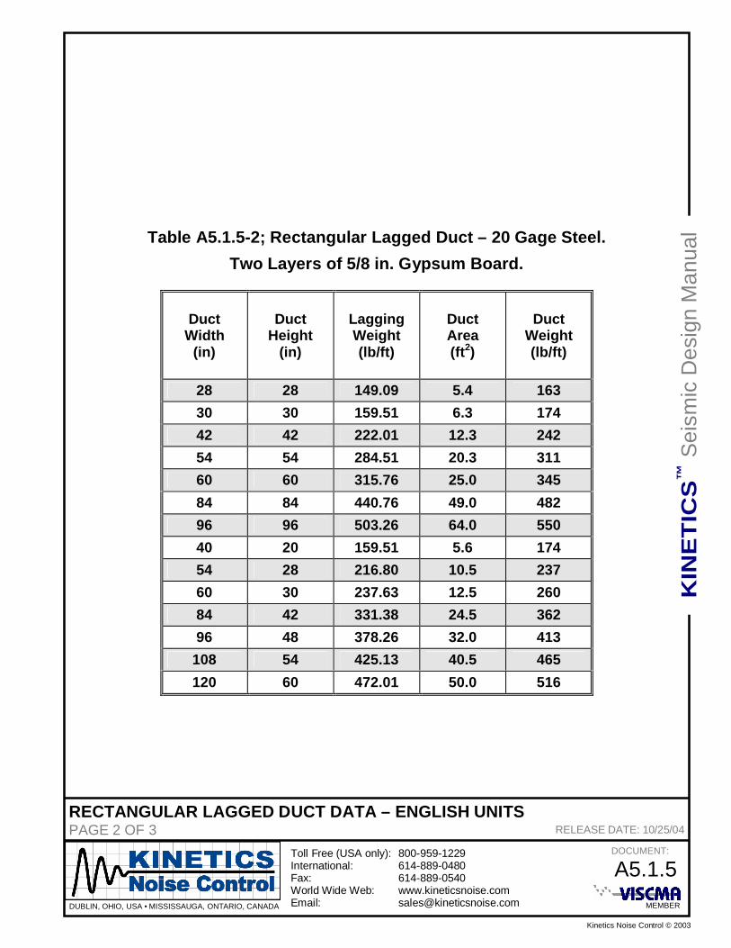
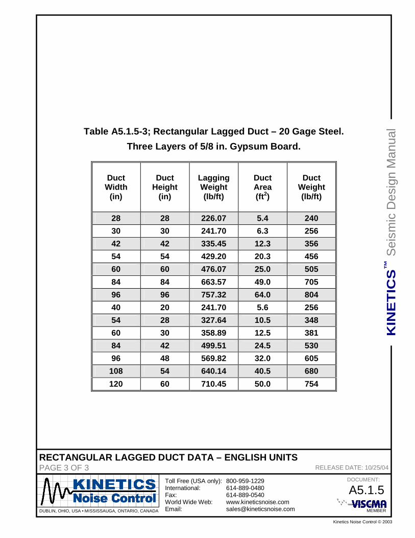
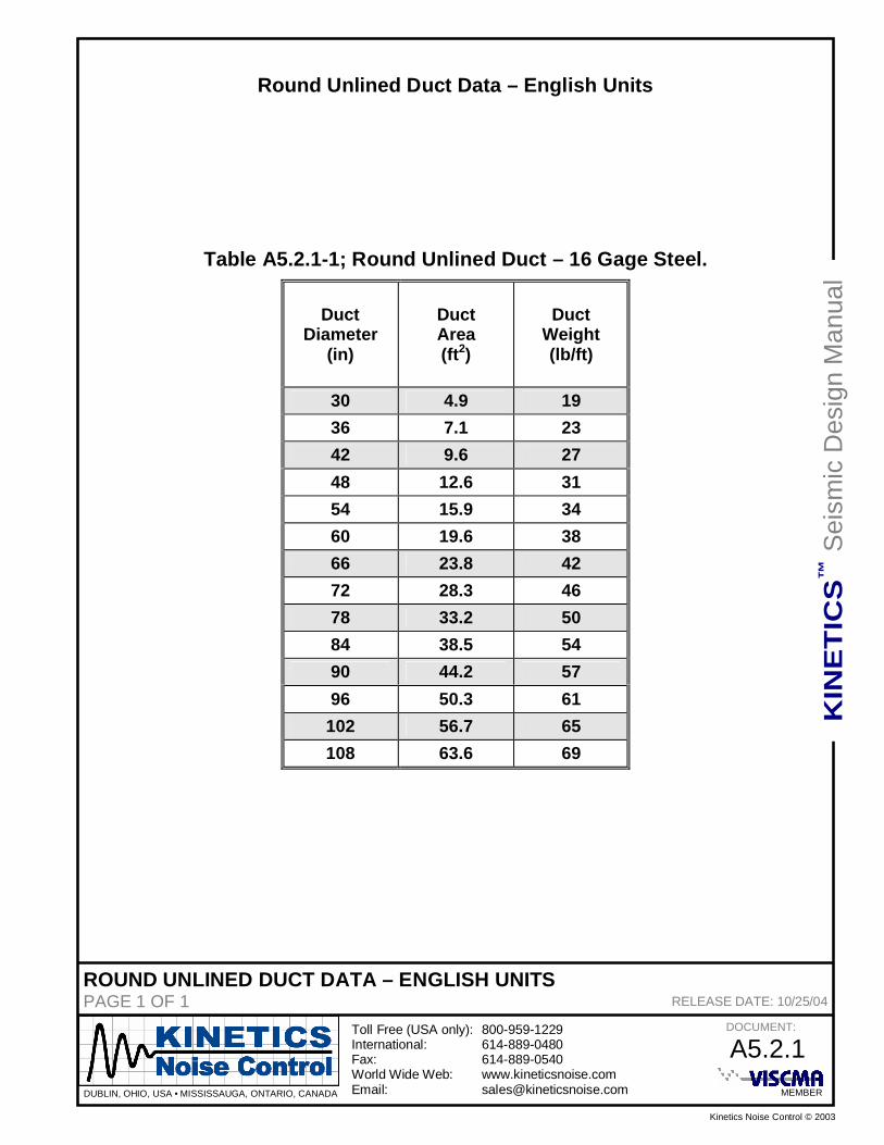
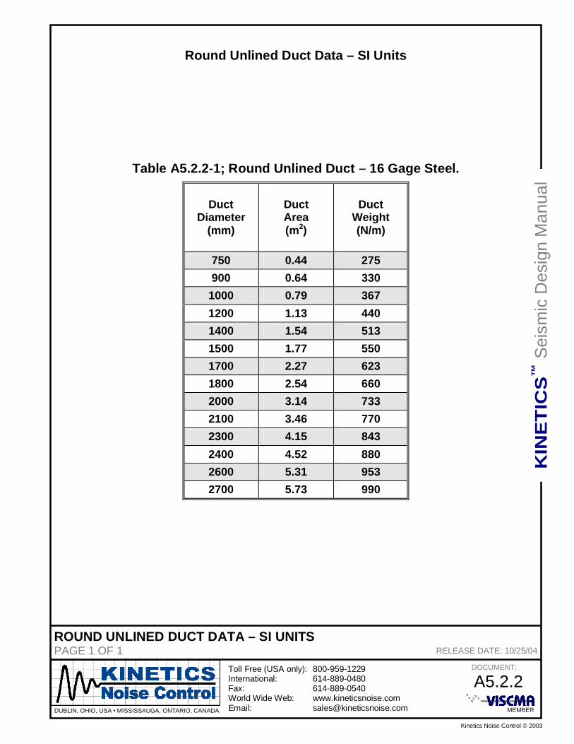
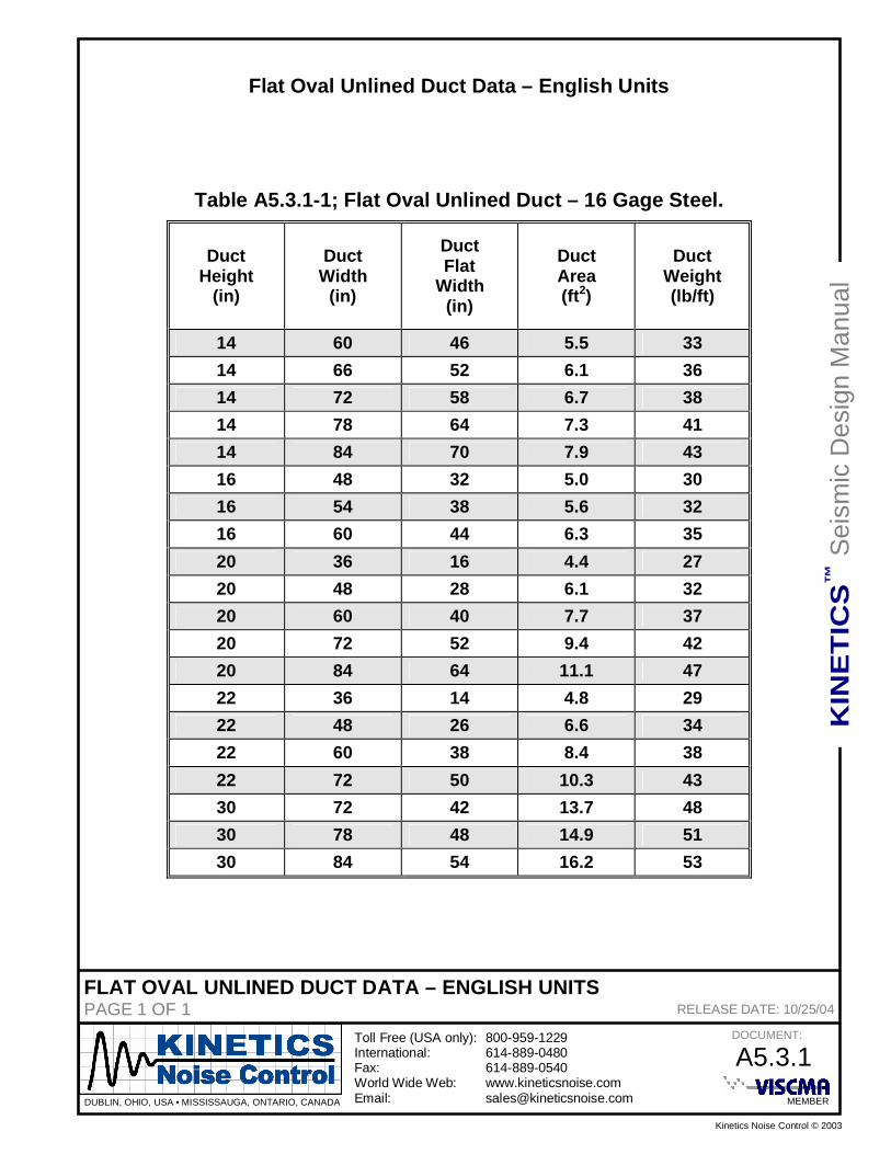
Electrical Conduit Data – English Units A4.5.1 Electrical Conduit Data – SI Units A4.5.2 DUCT DATA TABLES A5.0 Rectangular Unlined Duct Data – English Units A5.1.1 Rectangular Unlined Duct Data – SI Units A5.1.2 Rectangular Lined Duct Data (1.5 pcf Liner) – English Units A5.1.3 Rectangular Lined Duct Data (1.5 pcf Liner) – SI Units A5.1.4 Rectangular Lagged Duct Data (Gypsum Lagging) – English Units A5.1.5 Rectangular Lagged Duct Data (Gypsum Lagging) – SI Units A5.1.6 Round Unlined Duct Data – English Units A5.2.1 Round Unlined Duct Data – SI Units A5.2.2 Flat Oval Unlined Duct Data – English Units A5.3.1 Flat Oval Unlined Duct Data – SI Units A5.3.2 SEISMIC RESTRAINT TESTING A6.0 Restraint Element Deflection Limits A6.1.1 FASTENER DATA A7.0 Seismic Design Data for Bolts & Cap Screws A7.1 Seismic Design Data for Sheet Metal Screws A7.2 Seismic Design Data for Lag Screws A7.3 Seismic Design Data for Wood Screws A7.4
KINETICS™ Seismic & Wind Design Manual Section A
MASTER DOCUMENT PAGE 3 of 3 SECTION – A Toll Free (USA Only): 800-959-1229 RELEASED ON: 4/23/2014 International: 614-889-0480 FAX 614-889-0540 World Wide Web: www.kineticsnoise.com E-mail: [email protected] Dublin, Ohio, USA ∙ Cambridge, Ontario, Canada
ROD STIFFENER SELECTION DATA A8.0 KHRC-A Rod Stiffener Data for 0° ≤ A ≤ 30° A8.1.1 KHRC-A Rod Stiffener Data for 30° < A ≤ 45° A8.2.1 KHRC-A Rod Stiffener Data for 45° < A ≤ 60° A8.3.1 ELECTRICAL DESIGN DATA A9.0 EMT – Electrical Conduit Data A9.1.1 IMC – Electrical Conduit Data A9.2.1 Rigid – Electrical Conduit Data A9.3.1 GLOSSARY A10.0 REFERENCES A11.0
INSPECTION PREPARATION CHECKLISTPAGE 1 of 1 SECTION – A1.1
Toll Free (USA Only): 800-959-1229 RELEASED ON: 4/24/2014International: 614-889-0480FAX 614-889-0540World Wide Web: www.kineticsnoise.comE-mail: [email protected]
Dublin, Ohio, USA Cambridge, Ontario, Canada
INSPECTION PREPARATION CHECKLIST
In preparation for a field inspection, the following is a list of recommended inspection items andproject documents that will be needed in the field to document the conformance of the projectunder review to the certifications provided by KNC.
Before even considering performing a review, the individual performing the inspection must have athorough knowledge of what is required for seismic compliance. This includes at least 4 hours oftraining in this area from Kinetics office staff and a good broad knowledge of what is in theKinetics Seismic Design and Pipe and Duct manuals and how to quickly locate answers to specificquestions.
Tools:
1) Camera (4 mp or higher resolution digital camera that can produce decent pictures inrelatively low light conditions.)
2) Tape Measure (Good for measuring equipment dimensions, edge distances, etc)3) Ultrasonic measuring device (for working with longer spans like pipe and duct)4) Flashlight5) Laser pointer (not required, but handy if it is planned that you will be pointing things out to
contractors in the field.)6) Hard clip pad that can act as a surface to write against7) Colored pens that will show up clearly when writing on black and white documents.8) Additional paper for sketches and other notes
Project Documentation:
1) Clear definition of Project Scope as defined and agreed to at the proposal level (this canserve to limit scope creep when we are looking at things in the field).
2) A copy of the applicable submittal documentation packet (letter size docs) provided byKNC for the equipment/systems under review.
3) A copy of all applicable pipe/duct/electrical distribution drawings. Ideally these should bein an easily handled size (like 11 x 17), but only as long as the reduced size is legible andcan easily be worked with.
4) A numbered listing of potential deficiencies likely to be present on equipment,piping/ductwork/electrical distribution systems being inspected that can act as a key whenmarking comments on the “inspection” copy of the drawings or other documents.
Additional Support Information:
1) Either a thorough and complete knowledge of the appropriate sections of the KineticsSeismic and/or Pipe and Duct manuals (as appropriate) or copies of those sections thatcan be used for reference.
EQUIPMENT INSPECTION INSTRUCTIONSPAGE 1 of 5 SECTION – A1.2
Toll Free (USA Only): 800-959-1229 RELEASED ON: 04/24/2014International: 614-889-0480FAX 614-889-0540World Wide Web: www.kineticsnoise.comE-mail: [email protected]
Dublin, Ohio, USA Cambridge, Ontario, Canada
INSPECTING DISTRIBUTION SYSTEMS
A1.2.1 Scope:
When inspecting Distribution Systems (Pipe, Duct, Conduit, etc) in the field, it is important tomaintain an awareness of the scope of the Kinetics Noise Control’s (KNC) Certification andrecognize that KNC must limit comments and observations as much as possible to the confines ofthat scope. It is a regular occurrence in the field for the installation contractors to ask KNCrepresentatives to offer comments and even make decisions for items that KNC as a design teammay have nothing to do with. It is also common to be asked to discuss aspects of equipmentbeyond the bounds of the actual restraint connection. An example might have to do with thedurability of a contractor designed support bracket or the ability of a masonry wall to resist thedesign forces. These components would be beyond KNC’s control and must be referred to theStructural Engineer of Record. In order to offer any design input or guidance on items such asthis implies that whoever is offering that input fully understands all of the loads being carried bythe item, what it’s total capacity might be and is willing to take responsibility for that knowledge.
KNC’s involvement in a project is legally limited to those components provided by KNC. Thescope is therefore limited to those issues related to the proper selection and installation of thosepieces of hardware that restrain the distribution system to the structure. It includes the anchors orbolts that connect the restraint to the structure, the restraint components provided by KNC and theattachment of the restraint to the piping, ductwork or conduit. With the exception of generic A307hardware with industry standard ratings, any non-KNC component provided by others would beoutside of KNC’s ability to offer any binding recommendation or certification.
The scope also does not include an evaluation of the building structure and its ability to resist theloads applied to it. Only the engineer of record for that structure can state categorically that thestructure is capable of resisting the design loads.
Further, KNC must limit the scope of the inspection to only those objects that can be seen. KNCcannot offer any positive comments on attachments or components that are hidden from view.
It is recommended that the Installation Contractor inspect his own equipment using this checklistprior to having the equipment inspected by an external organization. This will allow corrections tobe made prior to an official inspection and will make it much more likely that the inspection will bepassed successfully.
Special Note: As rod stiffener requirements cannot be fully evaluated until specific site conditionsare known, they are not designed and specified by KNC except under special circumstances.Section D4.4 of this manual includes a “tool” that allows contractors to determine specificrequirements for this purpose. Should the contractor wish for KNC to take responsibility for thesizing and installation of these components, it will be necessary to collect data in the field, processit and generate a report for each restraint location. In the field, 5 minutes should be allowed to
EQUIPMENT INSPECTION INSTRUCTIONSPAGE 2 of 5 SECTION – A1.2
Toll Free (USA Only): 800-959-1229 RELEASED ON: 04/24/2014International: 614-889-0480FAX 614-889-0540World Wide Web: www.kineticsnoise.comE-mail: [email protected]
Dublin, Ohio, USA Cambridge, Ontario, Canada
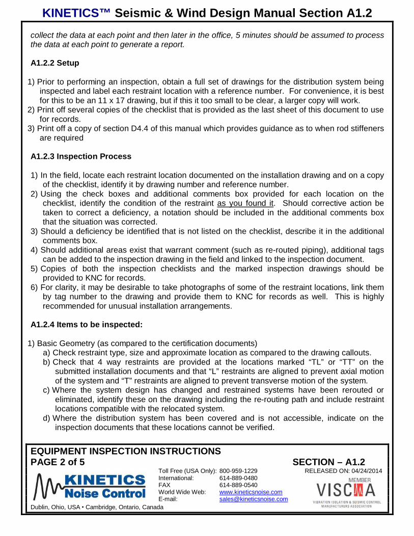
collect the data at each point and then later in the office, 5 minutes should be assumed to processthe data at each point to generate a report.
A1.2.2 Setup
1) Prior to performing an inspection, obtain a full set of drawings for the distribution system beinginspected and label each restraint location with a reference number. For convenience, it is bestfor this to be an 11 x 17 drawing, but if this it too small to be clear, a larger copy will work.
2) Print off several copies of the checklist that is provided as the last sheet of this document to usefor records.
3) Print off a copy of section D4.4 of this manual which provides guidance as to when rod stiffenersare required
A1.2.3 Inspection Process
1) In the field, locate each restraint location documented on the installation drawing and on a copyof the checklist, identify it by drawing number and reference number.
2) Using the check boxes and additional comments box provided for each location on thechecklist, identify the condition of the restraint as you found it. Should corrective action betaken to correct a deficiency, a notation should be included in the additional comments boxthat the situation was corrected.
3) Should a deficiency be identified that is not listed on the checklist, describe it in the additionalcomments box.
4) Should additional areas exist that warrant comment (such as re-routed piping), additional tagscan be added to the inspection drawing in the field and linked to the inspection document.
5) Copies of both the inspection checklists and the marked inspection drawings should beprovided to KNC for records.
6) For clarity, it may be desirable to take photographs of some of the restraint locations, link themby tag number to the drawing and provide them to KNC for records as well. This is highlyrecommended for unusual installation arrangements.
A1.2.4 Items to be inspected:
1) Basic Geometry (as compared to the certification documents)a) Check restraint type, size and approximate location as compared to the drawing callouts.b) Check that 4 way restraints are provided at the locations marked “TL” or “TT” on the
submitted installation documents and that “L” restraints are aligned to prevent axial motionof the system and “T” restraints are aligned to prevent transverse motion of the system.
c) Where the system design has changed and restrained systems have been rerouted oreliminated, identify these on the drawing including the re-routing path and include restraintlocations compatible with the relocated system.
d) Where the distribution system has been covered and is not accessible, indicate on theinspection documents that these locations cannot be verified.
EQUIPMENT INSPECTION INSTRUCTIONSPAGE 3 of 5 SECTION – A1.2
Toll Free (USA Only): 800-959-1229 RELEASED ON: 04/24/2014International: 614-889-0480FAX 614-889-0540World Wide Web: www.kineticsnoise.comE-mail: [email protected]
Dublin, Ohio, USA Cambridge, Ontario, Canada
2) Exemptionsa) If a Restraint has been eliminate due to and exemption condition (most likely the 12” rule),
ensure that all other required factors apply (Free swinging connector, adequate swingclearance, adequate flex at equipment attachment points, no mismatched [over 12” longsupports] on the run.)
3) Restraint Factorsa) Verify that the Cable angles relative to the horizontal plane are consistent with the
documentation provided (Note: in general this permits a maximum 60 deg angle from thehorizontal plane for the cables, but in some cases may limit the angle to 45 deg. This limitwould be indentified on the project specific tabulated restraint sizing charts (listing thebubble codes)).
b) Verify that the Cable angles relative to one another as viewed in the plan view are within 10degrees of being aligned.
c) Visually inspect the hardware used for size compliance versus the drawing callout.d) Cables must be installed in a snug (non-isolated) or near snug (isolated) condition.
4) Structural Attachment Factorsa) Ensure that the connections to the structure are aligned with the restraint cables.b) If a KSCA clip is used, that a single anchor are located in the hole closest to the cable end.c) Compare the connection viewed in the field to an arrangement drawing representative of
the connection specified on the drawing. A pictorial representation is present on therestraint cover sheet generated by KNC.
d) Ensure that restraint connections are made using KNC provided hardware. Connectionsmade without KNC hardware have not been tested and ratings cannot be verified.
e) Check that attachments made via beam clamps are positive and that beam clamps areequipped with straps of sufficient capacity to ensure that the beam clamps cannot be pulledoff the beam by lateral forces.
5) Component Attachment Factorsa) Ensure that the connections to the component will positively prevent relative motion
between the component and the restraint. (ie: clevis support hangers cannot be used inconjunction with Longitudinal (L) restraints and ductwork must also be adequately screwedto support trapeze bars to resist Longitudinal (L) forces.)
b) Transverse and/or Longitudinal restraints must connect to the distribution system within 4inches of a support point.
6) Hanger Rod Issuesa) Ensure that Hanger rod is made of a material that can resist uplift forces (Rod or structure
shape, not cable or sheet metal strap)b) If the system is isolated, check that the isolator brackets are within ¼” of the support
structure and that they are fitted with limit stops that prevent the hanger rods from pushingup more than ¼” into the housing.
c) Refer to this manual, Section D4.4 to determine if Rod Stiffeners are required and for sizingpurposes.
EQUIPMENT INSPECTION INSTRUCTIONSPAGE 1 of 4 SECTION -A1.3
Toll Free (USA Only): 800-959-1229 RELEASED ON: 04/24/2014International: 614-889-0480FAX 614-889-0540World Wide Web: www.kineticsnoise.comE-mail: [email protected]
Dublin, Ohio, USA Cambridge, Ontario, Canada
INSPECTING EQUIPMENT
A1.3.1 Scope:
When inspecting equipment in the field, it is important to maintain an awareness of the scope ofthe Kinetics Noise Control’s (KNC) Certification and recognize that KNC must limit comments andobservations as much as possible to the confines of that scope. It is a regular occurrence in thefield for the installation contractors to ask KNC representatives to offer comments and even makedecisions for items that we have nothing to do with. It is also common to be asked to discussaspects of equipment beyond the bounds of the actual restraint connection. An example mighthave to do with the durability of an equipment stand or a masonry wall. These components wouldbe beyond KNC’s control and must be referred to the Structural Engineer of Record. In order tooffer any design input or guidance on items such as this implies that whoever is offering that inputfully understands all of the loads being carried by the item, what it’s total capacity might be and iswilling to take responsibility for that knowledge.
KNC’s scope is limited to those issues related to the direct attachment of the equipment to thestructure. It includes the anchorage to the structure, the restraint component and the attachmentof the restraint to the equipment. In some cases, it may include other KNC provided items likeInertia Bases, Structural frames or beams. All of these items, when provided by KNC, would fallinto KNC’s scope. If provided by others, they would not and legally KNC could not offer guidanceor input on them.
The scope also does not include an evaluation of the building structure and its ability to resist theloads applied to it. Only the engineer of record for that structure can state categorically that thestructure is capable of resisting the design loads.
Further, KNC must limit the scope of the inspection to only those objects that can be seen. KNCcannot offer any positive comments on attachments or components that are hidden from view.
It is recommended that the Installation Contractor inspect his own equipment using this checklistprior to having the equipment inspected by an external organization. This will allow corrections tobe made prior to an official inspection and will make it much more likely that the inspection will bepassed successfully.
A1.3.2 Items to be inspected:
1) Basic Geometry (as compared to the certification documents)a) Approximate overall mounting dimensions (this is particularly true for equipment that might
not be provided with “built in” mounting holes and instead, clips like the KSMS have beenfitted or holes were drilled for mounting by the contractor). Verify that the spacing betweenthe restraints and the quantity of restraints used combine to generate an arrangement thatis at least as good as that specified in the certification document. (Increasing the restraintquantity or spacing is good, decreased restraint quantity or spacing is not.)
EQUIPMENT INSPECTION INSTRUCTIONSPAGE 2 of 4 SECTION -A1.3
Toll Free (USA Only): 800-959-1229 RELEASED ON: 04/24/2014International: 614-889-0480FAX 614-889-0540World Wide Web: www.kineticsnoise.comE-mail: [email protected]
Dublin, Ohio, USA Cambridge, Ontario, Canada
b) Verify that the overall dimensions of the equipment appear to be in line with what has beenanalyzed. This does not need to be measured critically, a simple approximation isadequate.
2) Bolts, welds or anchors that attach to the structure.a) Verify that the anchors or bolts are at least as large as those identified in the certification
document.b) To the extent possible, check that the holes for these attachment points are not to be more
than 1/8” in diameter larger than the bolt body.c) If anchored to concrete, check that the edge distance and spacing meets the minimum
requirements called out on the certification document.d) Check that the anchors are installed at 90 degrees to the parent slab (vertical for floor
mounted equipment) and are not canted at an angle.e) If welded, verify that the welds are in conformance with those shown on the certification
document.
3) Restraint component.a) If an oversized base plate is shown as being required by the certification document, verify
that the appropriate sized base plate has been fitted.b) Check that the internal clearances in the snubbing element do not sum to more that 1/2” in
any axis (ie: since 1/4” movement is allowed in any direction, this can show up as 1/4” oneach side of the snubbing element or as 1/8” on one side and 3/8” on the other. This isparticularly critical for isolators like the FLS, FLSS and HS-1 where the installer controls thespacing.)
c) Ensure that all restraints called for are properly in place (particularly true for curb mountedequipment like KSR’s)
4) Bolts/welds that attach to the equipment.a) Verify that the restraint is attached to the equipment using all of the provided attachment
holes in the restraint or a weld equivalent to that identified on the certification document.b) Check that curb mounted equipment is positively connected to the curb or curb isolation
system.
5) Suspended equipmenta) Compare the installation to the certification document and ensure that if required, rod
stiffeners have been fitted.b) If the component is supported by only 2 hanger rods, check that the restraints are attached
to it at its approximate CG.c) Visually check that the cable angles are no steeper than 60 degrees from the horizontal
plane.d) Visually check that cables do not have excessive slack (they are to be snug, but not
tensioned).e) Visually check that cables are oriented approx 90 degrees apart when viewed looking
EQUIPMENT INSPECTION INSTRUCTIONSPAGE 3 of 4 SECTION -A1.3
Toll Free (USA Only): 800-959-1229 RELEASED ON: 04/24/2014International: 614-889-0480FAX 614-889-0540World Wide Web: www.kineticsnoise.comE-mail: [email protected]
Dublin, Ohio, USA Cambridge, Ontario, Canada
f) Visually check that cables are straight and are not contacting or distorted by an intermediateobstruction.
g) If the system is isolated, check that the isolator brackets are within ¼” of the supportstructure and that they are fitted with limit stops that prevent the hanger rods from pushingup more than ¼” into the housing.
6) Documentationa) Complete the Inspection Checklist for each piece of equipment indicating the observed
installed equipment condition and note any discrepancies.b) In performing this inspection, identify the condition of the piece of equipment as you found it.
Should corrective action be taken to correct a deficiency, A notation should be included inthe additional comments box of the checklist indicating that the situation was corrected.
c) Retain the installation Inspection Checklist for recordsd) Where appropriate, photos should be taken, linked to tags and retained for records as well.
Toll Free (USA Only): 800-959-1229 RELEASED ON: 4/25/2014International: 614-889-0480FAX 614-889-0540World Wide Web: www.kineticsnoise.comE-mail: [email protected]
Dublin, Ohio, USA Cambridge, Ontario, Canada
HOUSEKEEPING PAD DESIGN
The following section identifies those procedures that should be followed to ensure thatHousekeeping pads used in structures located in seismically prone areas, will remain intactand in place when exposed to a seismic event. However, no claims are made in thisdocument as to the ability of the structural slab underneath the housekeeping pad to withstandthe seismic loads being transmitted into it. The guide is offered solely as a recommendation toother engineers and contractors as a tool that can aid in selecting an appropriatehousekeeping pad design. As with other elements of the structure, the Engineer of record hasthe final say as to the suitability of these parameters to the project at hand.
A2.1.1 GeneralHousekeeping pads have been used for years as a device to allow isolated equipment to bemore easily kept clear of debris and to enhance both the time required for maintenance andthe appearance of mechanical rooms. As the demand for appropriate seismic restraint hasbecome more stringent, housekeeping pads have evolved to serve as a structural interfacethat distributes localized point loads generated by attached equipment to the more globallydesigned mechanical room floor structure.
It is not untypical for the anchorage embedment requirements for particular pieces ofequipment to exceed the maximum permitted embedment depth in a mechanical room floorslab. In these cases, the housekeeping slab thickness can be selected to meet the equipmentanchor needs and then through an array of anchors that connect the housekeeping pad to thestructure, this load can be distributed to a larger quantity of smaller anchors that arecompatible with the floor slab.
Critical to this interface is the housekeeping pad thickness, the grade of concrete used, theadequacy of the connection between the housekeeping pad and the floor slab and appropriatereinforcement in the housekeeping pad to keep it from splitting apart. It is equally critical toensure that the equipment anchors can not rupture the housekeeping pad and pull free. Thisis accomplished by providing an adequate edge distance between the anchor and theperimeter of the housekeeping pad itself as well as proper spacing between the anchors.
A2.1.2 Housekeeping Pad Thickness and Perimeter DimensionsBefore specifying a housekeeping pad, it is critical to determine the size and locations of theanchors that are being used to attach the equipment. Kinetics Noise Control or some otherreputable source should perform an analysis, with the appropriate mounting hardware beingselected and mounting locations determined. Once anchors are selected, the embedmentdepth for the anchors can be identified. This is generally 8 times the anchor diameter, but in afew cases, could be more. Refer to the Anchor section (P10) in this manual or the calculationperformed to verify this dimension. As it is necessary that anchors be embedded in a singlecontiguous pour, it will be necessary for the anchor to achieve its full embedment in either thestructural floor slab or the housekeeping pad. The only exception to this is when the
Toll Free (USA Only): 800-959-1229 RELEASED ON: 4/25/2014International: 614-889-0480FAX 614-889-0540World Wide Web: www.kineticsnoise.comE-mail: [email protected]
Dublin, Ohio, USA Cambridge, Ontario, Canada
housekeeping pad has been poured along with the structural slab. In addition, for mostapplications using KCCAB anchors at least 1” of cover under the anchor is required. Thus, if6” of embedment is required for the anchor, a minimum contiguous concrete thickness of 7” isneeded to accommodate this. (Note, if the anchor is being directly embedded into a slab ongrade, the minimum cover over the end of the anchor increases to 1-1/2”.
Referring also to the Anchor section (P10) of this manual, the minimum allowed edge distanceis also identified by anchor size. This is the minimum allowed distance from the anchorcenterline to the nearest edge of a housekeeping pad. Using this information along with thepreviously identified anchor attachment pattern, a minimum housekeeping pad profile can bedetermined.
Figure A2.1-1; Housekeeping pad layout
Housekeeping Pad General Layout
A2.1.3 Tabulated Design Data AssumptionsIn using the tabulated data listed in this section, the following assumptions have been made.
1) The concrete used is in the housekeeping pad is 3000 psi min, standard weight.
Toll Free (USA Only): 800-959-1229 RELEASED ON: 4/25/2014International: 614-889-0480FAX 614-889-0540World Wide Web: www.kineticsnoise.comE-mail: [email protected]
Dublin, Ohio, USA Cambridge, Ontario, Canada
2) Anchorage ratings have been de-rated to meet current US standards for all applicationsexcept those requiring certification from OSHPD.
3) The structural concrete used is 3000 psi min and standard weight.4) The thickness and profile are in accordance with the sizing information listed above.5) The housekeeping pad is attached to the structural slab using 3/8” diameter x 5” long
KCAB anchor bolts that are embedded 3” into the structural slab, protrude 2” into thehousekeeping pad and are physically connected to internal #3 rebar using KSUA clips. (Itis only possible to use larger anchors if the structural slab is greater than 4” in thickness.)
A2.1.4 Use of Tables1) Divide the total Operating Equipment weight by the overall length of the housekeeping pad
to get a weight per foot value.2) Verify that the vertical dimension from the top of the housekeeping pad to the equipment
CG is less than the 2/3 of the width of the housekeeping pad. (If this is not the case, eitherthe pad will have to be made wider or a custom analysis will have to be performed byKinetics Noise Control or other qualified source.)
3) Determine the Seismic acceleration for the equipment type and location in the structureunder review. All acceleration values are listed in the attached tables include all factorsand are expressed in stress based (ASD) units regardless of the code used. If the designforces are LRFD based as in the IBC or TI-809-04, the values should be reduced by afactor of 0.7 prior to using these tables. (Note: this has already been done if using KineticsNoise Control provided certification documents.) If factors are provided in the projectspecification that exceed the code values, the higher values should be used as a basis fordesign.
4) Select the table with the appropriate design acceleration factor.5) Reading across the top of the table, find the equipment weight per foot and the
housekeeping pad thickness previously determined6) Read down the column until you find the housekeeping width that will allow the equipment
mounting anchors to be installed and maintain adequate edge distances.7) The value listed in upper portion of the table is the maximum center to center distance for
anchors placed around the perimeter of the housekeeping pad.8) The value listed in lower portion of the table is the maximum spacing between anchors in
the central area of the housekeeping pad.9) A minimum of 4 anchors is required per pad.10) Refer to the drawing below for reinforcement and housekeeping pad details.11) All pad reinforcement should conform to ACI standards for minimum area and concrete
coverage.
A2.1.5 Special ApplicationsFor Design conditions outside of those allowed by the above Tables, consult Kinetics NoiseControl.
Toll Free (USA Only): 800-959-1229 RELEASED ON: 4/25/2014International: 614-889-0480FAX 614-889-0540World Wide Web: www.kineticsnoise.comE-mail: [email protected]
Dublin, Ohio, USA Cambridge, Ontario, Canada
A2.1.6 Sample Pad DesignConditions:10,000 lb chillerSeismic Acceleration .47 g (in ASD units at equipment location)Anchorage spacing (from equipment) 112” x 48”Anchor size (from equipment analysis) .75”
Pad ThicknessEmbedment required for .75” anchor is 6” (from anchor table in P10.2.1 of this manual).Minimum cover is .75” so minimum thickness is 6.75”. Use 8” pad.
Pad LengthMinimum edge distance for .75” anchor is 9.75” (from anchor table in P10.2.1 of this manual).Minimum pad length is 9.75” (edge distance) + 112” (spacing) + 9.75” (edge distance) or131.5” (call it 11 ft).
Pad WidthUsing above minimum edge distance the minimum width is 9.75” (edge distance) + 48”(spacing) + 9.75” (edge distance) or 67.5”
Weight per foot of length is 10,000/11 or 909 lb/ft.
Refering to the .5g table and the 1000 lb/ft column with an 8” thick pad, the maximumperimeter anchor spacing for a 4-6 ft wide pad is 36”. The maximum central area anchorspacing is 48”.
Table A2.1-1; Design Tables
Seismic Acceleration (at Equipment) 0.25 g ASD Based Values With IBC, or TI-809-04 code reduce the LRFD "g" value by 0.7
RESTRAINT ELEMENT DEFLECTION LIMITSPAGE 1 OF 8 RELEASE DATE: 9/3/04
Restraint Element Deflection Limits
Introduction:
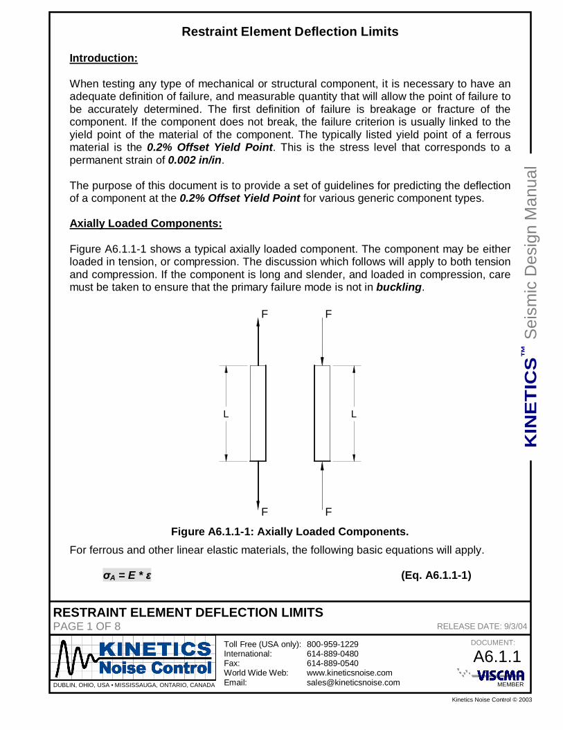
When testing any type of mechanical or structural component, it is necessary to have anadequate definition of failure, and measurable quantity that will allow the point of failure tobe accurately determined. The first definition of failure is breakage or fracture of thecomponent. If the component does not break, the failure criterion is usually linked to theyield point of the material of the component. The typically listed yield point of a ferrousmaterial is the 0.2% Offset Yield Point. This is the stress level that corresponds to apermanent strain of 0.002 in/in.
The purpose of this document is to provide a set of guidelines for predicting the deflectionof a component at the 0.2% Offset Yield Point for various generic component types.
Axially Loaded Components:
Figure A6.1.1-1 shows a typical axially loaded component. The component may be eitherloaded in tension, or compression. The discussion which follows will apply to both tensionand compression. If the component is long and slender, and loaded in compression, caremust be taken to ensure that the primary failure mode is not in buckling.
F
F F
F
L L
Figure A6.1.1-1: Axially Loaded Components.For ferrous and other linear elastic materials, the following basic equations will apply.
RESTRAINT ELEMENT DEFLECTION LIMITSPAGE 2 OF 8 RELEASE DATE: 9/3/04
Where:E = the elastic modulus of component material, also known as Young’s Modulus.
= the strain in the component.A = the axial stress in the component.
The strain acting in the component, , is defined as the change in the length, L, of thecomponent under the action of the force F divided by the unloaded length, L, of thecomponent, or:
= L / L (Eq. A6.1.1-2)
Rearrange Equation A6.1.1-1 to solve for .
= A / E (Eq. A6.1.1-3)
Set Equation A6.1.1-2 equal to Equation A6.1.1-3, and solve for L.
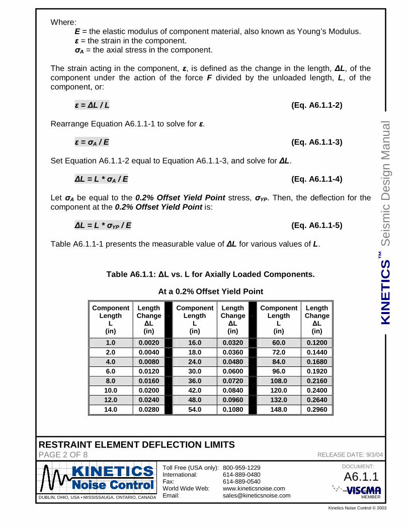
L = L * A / E (Eq. A6.1.1-4)
Let A be equal to the 0.2% Offset Yield Point stress, YP. Then, the deflection for thecomponent at the 0.2% Offset Yield Point is:
L = L * YP / E (Eq. A6.1.1-5)
Table A6.1.1-1 presents the measurable value of L for various values of L.
Table A6.1.1: L vs. L for Axially Loaded Components.
RESTRAINT ELEMENT DEFLECTION LIMITSPAGE 3 OF 8 RELEASE DATE: 9/3/04
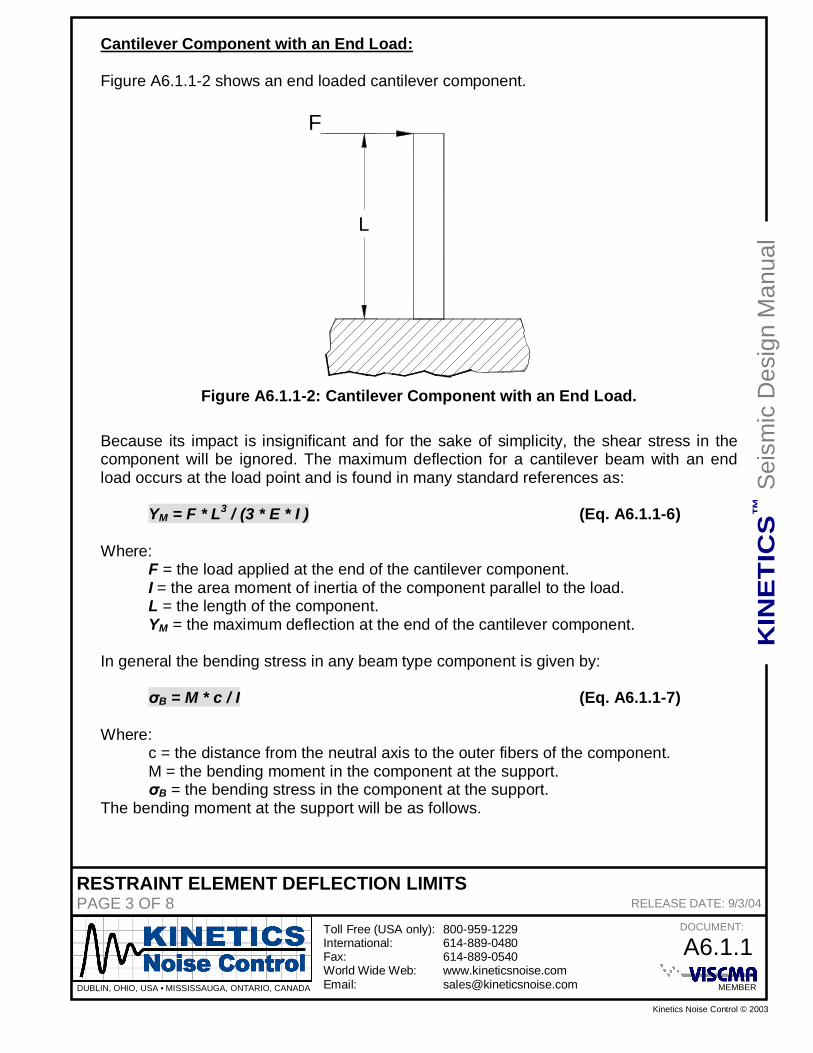
Cantilever Component with an End Load:
Figure A6.1.1-2 shows an end loaded cantilever component.
F
L
Figure A6.1.1-2: Cantilever Component with an End Load.
Because its impact is insignificant and for the sake of simplicity, the shear stress in thecomponent will be ignored. The maximum deflection for a cantilever beam with an endload occurs at the load point and is found in many standard references as:
YM = F * L3 / (3 * E * I ) (Eq. A6.1.1-6)
Where:F = the load applied at the end of the cantilever component.I = the area moment of inertia of the component parallel to the load.L = the length of the component.YM = the maximum deflection at the end of the cantilever component.
In general the bending stress in any beam type component is given by:
B = M * c / I (Eq. A6.1.1-7)
Where: c = the distance from the neutral axis to the outer fibers of the component. M = the bending moment in the component at the support.
B = the bending stress in the component at the support.The bending moment at the support will be as follows.
Figure A6.1.1-3 shows a simply supported component with a center load. As it isinsignificant and for simplicity’s sake, the shear stress in the component will be ignored.The maximum deflection for a simply supported beam with a center load occurs at theload point and is found in many standard references as:
YM = F * L3 / (48 * E * I ) (Eq. A6.1.1-12)
The maximum bending moment occurs at the center of the beam, and is given by:
RESTRAINT ELEMENT DEFLECTION LIMITSPAGE 6 OF 8 RELEASE DATE: 9/3/04
Component with Fixed Supports and a Center Load:
Figure A6.1.1-4 shows a component with fixed ends and a center load. Due to its minimalimpact and to simply the analysis, the shear stress in the component will be ignored.
F
L/2
L
Figure A6.1.1-4: Component with Fixed Ends and a Center Load.
The maximum deflection for a beam with fixed ends and a center load, again, occurs atthe load point and is found in many standard references as:
YM = F * L3 / (192 * E * I ) (Eq. A6.1.1-16)
The maximum bending moment occurs at the center of the beam, and is given by:
M = F * L / 8 (Eq. A6.1.1-17)
Following the same procedure as with the simply supported component, we may obtainthe following results.
YM = (1/24) * (L2 / c) *( YP / E) (Eq. A6.1.1-18)
The result in Equation A6.1.1-18 will be more useful if it is expressed in a dimensionlessform as shown below.
For the axially loaded components, Equation A6.1.1-5 may be written for a 0.2% OffsetYield Point as follows.
L / L = 0.002 (Eq. A6.1.1-20)
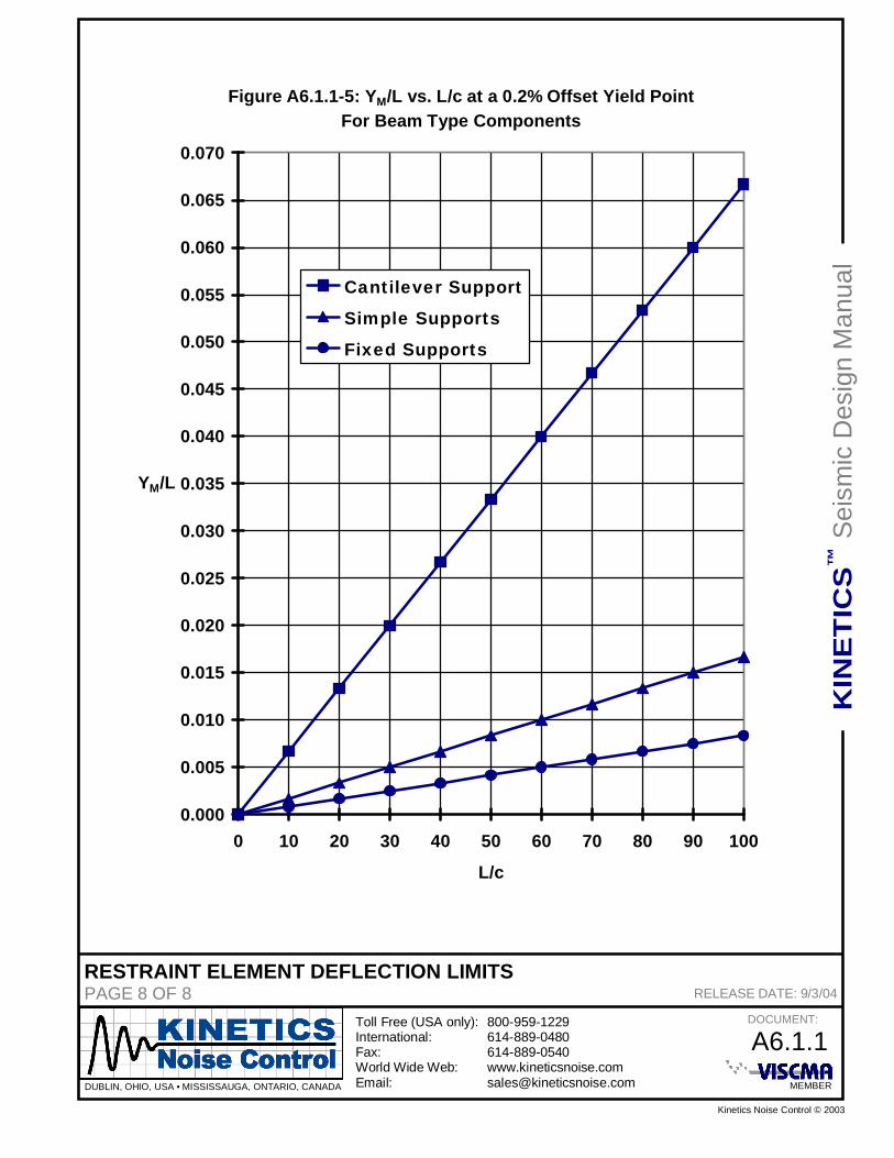
For the components that may be modeled as some type of beam element in bending, theresults in Tables A6.1.1-2 through A6.1.1-4 may be best summarized, and be more usefulin the graphical form as shown in Figure A6.1.1-5.
Equation A6.1.1-20 and Figure A6.1.1-5 will allow an investigator to predict the deflectionof a component at failure as defined by the 0.2% Offset Yield Stress. If significant plasticdeformation is to be permitted, then this deflection will allow the investigator to predict thedeflection at which plastic deformation has truly begun.
SEISMIC DESIGN DATA FOR LAG SCREWSPAGE 1 OF 5 RELEASE DATE: 11/2/04
Seismic Design Data for Lag Screws
Introduction:
Lag screws are used for connections and attachments to wooden structures. Care mustbe taken when using Lag Screws for critical installations because the effective strength ofthe connection will depend on the type, grade, and condition of the wood used in thestructure to which the connection is being made. This document will assume that thewood is an Eastern Soft Woods (Spruce-Pine-Fir(s)), Western Cedars, or WesternWoods with a Specific Gravity of 0.36. The tabulated values of allowable shear load, ZS,will be based on single shear with the load being perpendicular to the grain of the wood,and on the use of a 1/4 thick side plate. This will produce the most conservativeallowable values.
Lag Screw Basic Data:
A typical Hex Head Lag Screw is shown in Figure A7.3-1. The basic information istabulated in Table A7.3-1.
L
P
ØD
H
F
Figure A7.3-1; Typical Hex Head Lag Screw.
Table A7.3-1; Hex Head Lag Screw Dimensional Data.
SEISMIC DESIGN DATA FOR LAG SCREWSPAGE 2 OF 5 RELEASE DATE: 11/2/04
Lag Screw Installation Data:
The Basic Rules & Data for installing Lag Screws are illustrated in Figure A7.3-2 andTable A7.3-2. Do not install Lag Screws in the End Grain of a piece of wood forseismic applications!
S E1
ØD
E3
TE2
Ød
L
Figure A7.3-2; Typical Lag Screw Installation Guide.
SEISMIC DESIGN DATA FOR LAG SCREWSPAGE 4 OF 5 RELEASE DATE: 11/2/04
Lag Screw Allowable Load Data:
The Basic Allowable Load Data for Lag Screws with an embedment equal to eight (8)times the basic diameter, not including the point, are given in Figure A7.3-3 and TableA7.3-3. The basic allowable loads have been increased by a Duration Factor of 1.6 forseismic and wind loading. For an embedment of less than eight (8) times the basicdiameter, the values in Table A7.3-3 may be multiplied by the ratio of the actualembedment divided by eight (8) times the basic diameter.
E3=8D
T
P
L
ZS
ZT
A°
ZA
ØD
Figure A7.3-3; Typical Lag Screw in Combined Tension and Shear.
KHRC-A ROD STIFFENER DATA FOR 0° A 30° - GENERALPAGE 1 OF 10 RELEASE DATE: 10/12/05
KHRC-A Rod Stiffener Data for 0° A 30°
Introduction:
This document will aid the designer in determining if hanger rod reinforcement, rodstiffeners, will be required for a given application. If they are required, recommendationsfor a minimum stiffener size will be made. Also, rod stiffener clamp locations and spacingwill be made based on the use of Kinetics Noise Control model KHRC-A AdjustableAngle Stiffener Kit. This kit is a single clamp system that is shown in Figure A8.1.1-1. Onekit will be required for each clamp location. A minimum of two clamp kits will be requiredfor each hanger rod stiffener. The clamps and rod stiffener are assembled to the hangerrod as shown in Figure A8.1.1-2. The dimensions shown as L1, L2, and L3 are themaximum allowable installation dimensions for locating and spacing the KHRC-A clampkits.
Buckling Analysis:
Buckling failure is a catastrophic form of failure that occurs at stresses that are muchlower that those required to yield the material. It is more of a function of the geometry ofthe components than it is a function of the material. In general it is very difficult to predictthe onset of buckling. Thus, the approach used in this document will of necessity be veryconservative. All of the basic assumptions described below will lead to a conservativeresult.
There are many theories that address buckling In general there are long, intermediate,and short columns. For long columns, Euler’s formula is most often used with goodresults. For intermediate and short columns, there are many different approaches thatwould result in many iterative calculations for each case to be investigated. In order toprovide reliable results with reasonable time expenditures, Euler’s formula was used wasused to determine the maximum un-reinforced hanger rod length. The hanger rods weremodeled as having one end free, and one end fixed. If reinforcement was required for thehanger rod, it was selected based on the assumptions that the reinforcing angle wascarrying the entire compressive load, and that the reinforcing angle was equal to thelength of the hanger rod.
In a similar fashion, Euler’s formula was used to determine the maximum allowable valuesfor the clamp locating dimensions L1 and L3. However, in this case L1 and L3 assumed tobe equal to each other, and their sum was set to be equal to the maximum un-reinforcedlength of the hanger rod computed using Euler’s formula with one end of the rod fixed andthe other end free. In determining the maximum value for the clamp spacing, L2, Euler’sformula was used assuming that both ends of the hanger rod were fixed at the clamps.
The horizontal seismic loads applied to the hanger rods are based on the Kinetics NoiseControl Horizontal Force Class, or Force Class, designations of I through VI. The
KHRC-A ROD STIFFENER DATA FOR 0° A 30° - GENERALPAGE 2 OF 10 RELEASE DATE: 10/12/05
installation angle (A), as measured from the horizontal, was taken to be 30°, and will beused to cover the range of installation angles from 0° to 30° inclusively. The Force Classsystem ranges are shown below.
Force Class I: 0 lbs through 250 lbsForce Class II: 251 lbs through 500 lbsForce Class III: 501 lbs through 1,000 lbsForce Class IV: 1,001 lbs through 2,000 lbsForce Class V: 2,001 lbs through 5,000lbsForce Class VI: 5,001 lbs through 10,000lbs
The maximum load in each Force Class was used with a Factor of Safety of 2:1 indetermining the maximum un-reinforced hanger rod length, the minimum angle size to beused for the rod stiffener, and the values used for L1, L2, and L3.
Use of the KHRC-A Rod Stiffener Data Tables:1.) Data Tables: There is a hanger rod stiffener selection data table for each Force
Class.2.) Hanger Rod Sizes: The hanger rod sizes that may be used with the Kinetics
Noise Control model KHRC-A, and that are applicable for each Force Class arelisted across the top of each data table.
3.) Hanger Rod Length: The hanger rod lengths that are applicable are listed in theleft hand column of each table in and 12 multiples. The maximum reinforcedhanger rod length for each Force Class is the last entry in this column.
4.) Rod Stiffener Requirement: Determine the appropriate Force Class for theapplication. Select the column for the hanger rod size being used, and follow itdown to the hanger rod length being considered. If the word “Yes” is found in thisbox, a hanger rod stiffener will be required. If, on the other hand, the word “No” isfound in the box, then a hanger rod stiffener is not required. If the hanger rodlength being used falls in between two of the tabulated rod lengths, use the largervalue for the hanger rod length.
5.) Minimum Stiffener Angle Size: The minimum reinforcement angle size for eachhanger rod length in each Force Class is listed in the right hand column of eachtable. Use the minimum Stiffener Angle size that corresponds to the hanger rodlength used in step “4.)”.
6.) Maximum Installation Dimensions: The maximum allowable installationdimensions, L1, L2, and L3, are tabulated by hanger rod size beneath the rodstiffener selection data table for each Force Class.
7.) KHRC-A Clamp Kits: A minimum of two (2) Kinetics Noise Control modelKHRC-A clamps kits are required for each hanger rod stiffener installation. TheKHRC-A clamp kits should be spaced approximately from each end of the rodstiffener angle. The distance from where the hanger rod is attached to thesuspended component and the lower KHRC-A clamp kit must not exceed the valuefor L1 listed for the Force Class and hanger rod size being used. If the spacing
KHRC-A ROD STIFFENER DATA FOR 0° A 30° - GENERALPAGE 3 OF 10 RELEASE DATE: 10/12/05
between the two KHRC-A clamp kits exceeds the value of L2, maximum allowablespacing between clamps, listed for the Force Class and rod size for the application,another KHRC-A clamp kit must be added between the original pair. Finally, thedistance from the upper KHRC-A clamp kit where the hanger rod attaches to thestructure, or isolation hanger, must not exceed the value listed for L3, based on theForce Class and rod size being considered. Also note that the thumb screw shouldbe securely tightened. Pliers may be used after thumb screw is made finger tight.
KHRC-A ROD STIFFENER DATA FOR 0° A 30° - FORCE CLASS IPAGE 5 OF 10 RELEASE DATE: 10/12/05
RodLength ( )
3/8Rod
1/2Rod
5/8Rod
3/4Rod
7/8Rod Rod
1-1/4Rod
Minimum RodStiffener Angle
6 No No No No No No No ------------------------12 Yes No No No No No No 1 x 1 x 1/818 Yes Yes No No No No No 1 x 1 x 1/824 Yes Yes No No No No No 1 x 1 x 1/830 Yes Yes Yes No No No No 1 x 1 x 1/836 Yes Yes Yes No No No No 1 x 1 x 1/848 Yes Yes Yes Yes No No No 1 x 1 x 1/860 Yes Yes Yes Yes Yes No No 1-1/4 x 1-1/4 x 3/1672 Yes Yes Yes Yes Yes No No 1-1/4 x 1-1/4 x 3/1684 Yes Yes Yes Yes Yes Yes No 1-1/4 x 1-1/4 x 1/496 Yes Yes Yes Yes Yes Yes No 1-1/2 x 1-1/2 x 3/16
108 Yes Yes Yes Yes Yes Yes No 1-1/2 x 1-1/2 x 1/4120 Yes Yes Yes Yes Yes Yes No 1-1/2 x 1-1/2 x 1/4132 Yes Yes Yes Yes Yes Yes Yes 1-3/4 x 1-3/4 x 3/16144 Yes Yes Yes Yes Yes Yes Yes 1-3/4 x 1-3/4 x 1/4156 Yes Yes Yes Yes Yes Yes Yes 2 x 2 x 3/16168 Yes Yes Yes Yes Yes Yes Yes 2 x 2 x 3/16180 Yes Yes Yes Yes Yes Yes Yes 2 x 2 x 1/4192 Yes Yes Yes Yes Yes Yes Yes 2 x 2 x 5/16204 Yes Yes Yes Yes Yes Yes Yes 2 x 2 x 5/16216 Yes Yes Yes Yes Yes Yes Yes 2 x 2 x 3/8228 Yes Yes Yes Yes Yes Yes Yes 2 x 2 x 3/8
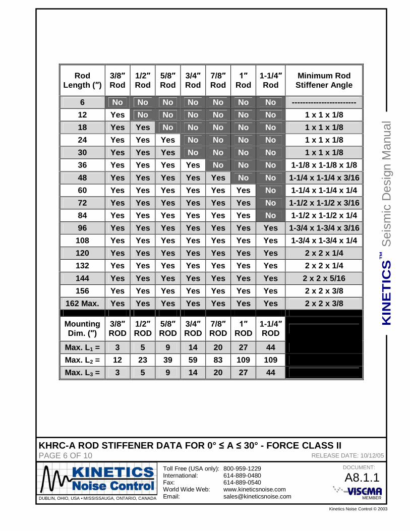
KHRC-A ROD STIFFENER DATA FOR 0° A 30° - FORCE CLASS IIPAGE 6 OF 10 RELEASE DATE: 10/12/05
RodLength ( )
3/8Rod
1/2Rod
5/8Rod
3/4Rod
7/8Rod Rod
1-1/4Rod
Minimum RodStiffener Angle
6 No No No No No No No ------------------------12 Yes No No No No No No 1 x 1 x 1/818 Yes Yes No No No No No 1 x 1 x 1/824 Yes Yes Yes No No No No 1 x 1 x 1/830 Yes Yes Yes No No No No 1 x 1 x 1/836 Yes Yes Yes Yes No No No 1-1/8 x 1-1/8 x 1/848 Yes Yes Yes Yes Yes No No 1-1/4 x 1-1/4 x 3/1660 Yes Yes Yes Yes Yes Yes No 1-1/4 x 1-1/4 x 1/472 Yes Yes Yes Yes Yes Yes No 1-1/2 x 1-1/2 x 3/1684 Yes Yes Yes Yes Yes Yes No 1-1/2 x 1-1/2 x 1/496 Yes Yes Yes Yes Yes Yes Yes 1-3/4 x 1-3/4 x 3/16
108 Yes Yes Yes Yes Yes Yes Yes 1-3/4 x 1-3/4 x 1/4120 Yes Yes Yes Yes Yes Yes Yes 2 x 2 x 1/4132 Yes Yes Yes Yes Yes Yes Yes 2 x 2 x 1/4144 Yes Yes Yes Yes Yes Yes Yes 2 x 2 x 5/16156 Yes Yes Yes Yes Yes Yes Yes 2 x 2 x 3/8
KHRC-A ROD STIFFENER DATA FOR 0° A 30° - FORCE CLASS IIIPAGE 7 OF 10 RELEASE DATE: 10/12/05
RodLength ( )
3/8Rod
1/2Rod
5/8Rod
3/4Rod
7/8Rod Rod
1-1/4Rod
Minimum RodStiffener Angle
6 Yes No No No No No No 1 x 1 x 1/812 Yes Yes No No No No No 1 x 1 x 1/818 Yes Yes Yes No No No No 1 x 1 x 1/824 Yes Yes Yes Yes No No No 1 x 1 x 1/830 Yes Yes Yes Yes Yes No No 1-1/4 x 1-1/4 x 3/1636 Yes Yes Yes Yes Yes No No 1-1/4 x 1-1/4 x 3/1648 Yes Yes Yes Yes Yes Yes No 1-1/2 x 1-1/2 x 3/1660 Yes Yes Yes Yes Yes Yes No 1-1/2x 1-1/2 x 1/472 Yes Yes Yes Yes Yes Yes Yes 1-3/4 x 1-3/4 x 1/484 Yes Yes Yes Yes Yes Yes Yes 2 x 2 x 3/1696 Yes Yes Yes Yes Yes Yes Yes 2 x 2 x 5/16
108 Yes Yes Yes Yes Yes Yes Yes 2 x 2 x 3/8114 Max. Yes Yes Yes Yes Yes Yes Yes 2 x 2 x 3/8
KHRC-A ROD STIFFENER DATA FOR 0° A 30° - FORCE CLASS IVPAGE 8 OF 10 RELEASE DATE: 10/12/05
RodLength ( )
3/8Rod
1/2Rod
5/8Rod
3/4Rod
7/8Rod Rod
1-1/4Rod
Minimum RodStiffener Angle
6 Yes No No No No No No 1 x 1 x 1/812 Yes Yes Yes No No No No 1 x 1 x 1/818 Yes Yes Yes Yes No No No 1-1/8 x 1-1/8 x 1/824 Yes Yes Yes Yes Yes No No 1-1/4 x 1-1/4 x 3/1630 Yes Yes Yes Yes Yes Yes No 1-1/4 x 1-1/4 x 1/436 Yes Yes Yes Yes Yes Yes No 1-1/2 x 1-1/2 x 3/1648 Yes Yes Yes Yes Yes Yes Yes 1-3/4 x 1-3/4 x 3/1660 Yes Yes Yes Yes Yes Yes Yes 2 x 2 x 1/472 Yes Yes Yes Yes Yes Yes Yes 2 x 2 x 5/16
KHRC-A ROD STIFFENER DATA FOR 0° A 30° - FORCE CLASS VPAGE 9 OF 10 RELEASE DATE: 10/12/05
RodLength ( )
1/2Rod
5/8Rod
3/4Rod
7/8Rod Rod
1-1/4Rod
Minimum RodStiffener Angle
6 Yes No No No No No 1 x 1 x 1/812 Yes Yes Yes No No No 1-1/8 x 1-1/8 x 1/818 Yes Yes Yes Yes Yes No 1-1/4 x 1-1/4 x 3/1624 Yes Yes Yes Yes Yes No 1-1/2 x 1-1/2 x 3/1630 Yes Yes Yes Yes Yes Yes 1-3/4 x 1-3/4 x 3/1636 Yes Yes Yes Yes Yes Yes 2 x 2 x 3/1648 Yes Yes Yes Yes Yes Yes 2 x 2 x 3/8
KHRC-A ROD STIFFENER DATA FOR 0° A 30° - FORCE CLASS VIPAGE 10 OF 10 RELEASE DATE: 10/12/05
RodLength ( )
1/2Rod
5/8Rod
3/4Rod
7/8Rod Rod
1-1/4Rod
Minimum RodStiffener Angle
6 Yes Yes No No No No 1 x 1 x 1/812 Yes Yes Yes Yes No No 1-1/4 x 1-1/4 x 3/1618 Yes Yes Yes Yes Yes No 1-1/2 x 1-1/2 x 1/424 Yes Yes Yes Yes Yes Yes 1-3/4 x 1-3/4 x 1/430 Yes Yes Yes Yes Yes Yes 2 x 2 x 1/4
KHRC-A ROD STIFFENER DATA FOR 30° < A 45° - GENERALPAGE 1 OF 10 RELEASE DATE: 10/12/05
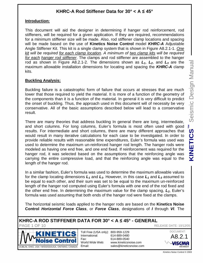
KHRC-A Rod Stiffener Data for 30° < A 45°
Introduction:
This document will aid the designer in determining if hanger rod reinforcement, rodstiffeners, will be required for a given application. If they are required, recommendationsfor a minimum stiffener size will be made. Also, rod stiffener clamp locations and spacingwill be made based on the use of Kinetics Noise Control model KHRC-A AdjustableAngle Stiffener Kit. This kit is a single clamp system that is shown in Figure A8.2.1-1. Onekit will be required for each clamp location. A minimum of two clamp kits will be requiredfor each hanger rod stiffener. The clamps and rod stiffener are assembled to the hangerrod as shown in Figure A8.2.1-2. The dimensions shown as L1, L2, and L3 are themaximum allowable installation dimensions for locating and spacing the KHRC-A clampkits.
Buckling Analysis:
Buckling failure is a catastrophic form of failure that occurs at stresses that are muchlower that those required to yield the material. It is more of a function of the geometry ofthe components than it is a function of the material. In general it is very difficult to predictthe onset of buckling. Thus, the approach used in this document will of necessity be veryconservative. All of the basic assumptions described below will lead to a conservativeresult.
There are many theories that address buckling In general there are long, intermediate,and short columns. For long columns, Euler’s formula is most often used with goodresults. For intermediate and short columns, there are many different approaches thatwould result in many iterative calculations for each case to be investigated. In order toprovide reliable results with reasonable time expenditures, Euler’s formula was used wasused to determine the maximum un-reinforced hanger rod length. The hanger rods weremodeled as having one end free, and one end fixed. If reinforcement was required for thehanger rod, it was selected based on the assumptions that the reinforcing angle wascarrying the entire compressive load, and that the reinforcing angle was equal to thelength of the hanger rod.
In a similar fashion, Euler’s formula was used to determine the maximum allowable valuesfor the clamp locating dimensions L1 and L3. However, in this case L1 and L3 assumed tobe equal to each other, and their sum was set to be equal to the maximum un-reinforcedlength of the hanger rod computed using Euler’s formula with one end of the rod fixed andthe other end free. In determining the maximum value for the clamp spacing, L2, Euler’sformula was used assuming that both ends of the hanger rod were fixed at the clamps.
The horizontal seismic loads applied to the hanger rods are based on the Kinetics NoiseControl Horizontal Force Class, or Force Class, designations of I through VI. The
KHRC-A ROD STIFFENER DATA FOR 30° < A 45° - GENERALPAGE 2 OF 10 RELEASE DATE: 10/12/05
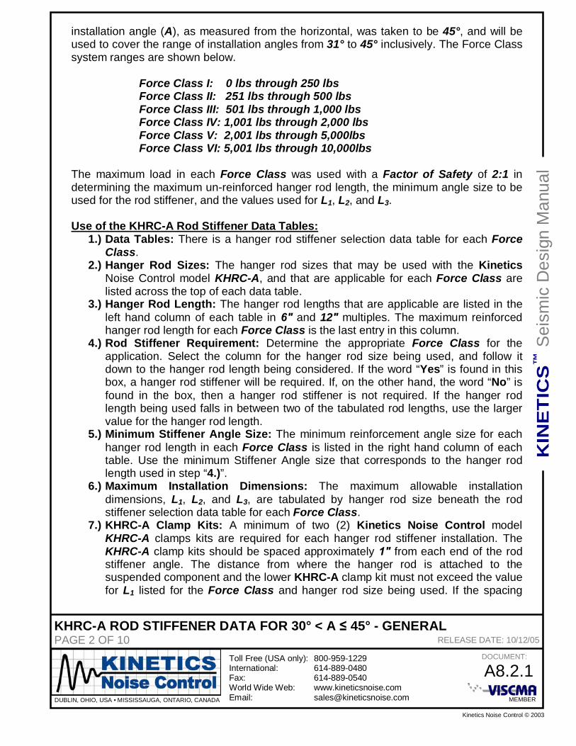
installation angle (A), as measured from the horizontal, was taken to be 45°, and will beused to cover the range of installation angles from 31° to 45° inclusively. The Force Classsystem ranges are shown below.
Force Class I: 0 lbs through 250 lbsForce Class II: 251 lbs through 500 lbsForce Class III: 501 lbs through 1,000 lbsForce Class IV: 1,001 lbs through 2,000 lbsForce Class V: 2,001 lbs through 5,000lbsForce Class VI: 5,001 lbs through 10,000lbs
The maximum load in each Force Class was used with a Factor of Safety of 2:1 indetermining the maximum un-reinforced hanger rod length, the minimum angle size to beused for the rod stiffener, and the values used for L1, L2, and L3.
Use of the KHRC-A Rod Stiffener Data Tables:1.) Data Tables: There is a hanger rod stiffener selection data table for each Force
Class.2.) Hanger Rod Sizes: The hanger rod sizes that may be used with the Kinetics
Noise Control model KHRC-A, and that are applicable for each Force Class arelisted across the top of each data table.
3.) Hanger Rod Length: The hanger rod lengths that are applicable are listed in theleft hand column of each table in and 12 multiples. The maximum reinforcedhanger rod length for each Force Class is the last entry in this column.
4.) Rod Stiffener Requirement: Determine the appropriate Force Class for theapplication. Select the column for the hanger rod size being used, and follow itdown to the hanger rod length being considered. If the word “Yes” is found in thisbox, a hanger rod stiffener will be required. If, on the other hand, the word “No” isfound in the box, then a hanger rod stiffener is not required. If the hanger rodlength being used falls in between two of the tabulated rod lengths, use the largervalue for the hanger rod length.
5.) Minimum Stiffener Angle Size: The minimum reinforcement angle size for eachhanger rod length in each Force Class is listed in the right hand column of eachtable. Use the minimum Stiffener Angle size that corresponds to the hanger rodlength used in step “4.)”.
6.) Maximum Installation Dimensions: The maximum allowable installationdimensions, L1, L2, and L3, are tabulated by hanger rod size beneath the rodstiffener selection data table for each Force Class.
7.) KHRC-A Clamp Kits: A minimum of two (2) Kinetics Noise Control modelKHRC-A clamps kits are required for each hanger rod stiffener installation. TheKHRC-A clamp kits should be spaced approximately from each end of the rodstiffener angle. The distance from where the hanger rod is attached to thesuspended component and the lower KHRC-A clamp kit must not exceed the valuefor L1 listed for the Force Class and hanger rod size being used. If the spacing
KHRC-A ROD STIFFENER DATA FOR 30° < A 45° - GENERALPAGE 3 OF 10 RELEASE DATE: 10/12/05
between the two KHRC-A clamp kits exceeds the value of L2, maximum allowablespacing between clamps, listed for the Force Class and rod size for the application,another KHRC-A clamp kit must be added between the original pair. Finally, thedistance from the upper KHRC-A clamp kit where the hanger rod attaches to thestructure, or isolation hanger, must not exceed the value listed for L3, based on theForce Class and rod size being considered. Also note that the thumb screw shouldbe securely tightened. Pliers may be used after thumb screw is made finger tight.
KHRC-A ROD STIFFENER DATA FOR 30° < A 45° - FORCE CLASS IPAGE 5 OF 10 RELEASE DATE: 10/12/05
RodLength ( )
3/8Rod
1/2Rod
5/8Rod
3/4Rod
7/8Rod Rod
1-1/4Rod
Minimum RodStiffener Angle
6 No No No No No No No ------------------------12 Yes No No No No No No 1 x 1 x 1/818 Yes Yes No No No No No 1 x 1 x 1/824 Yes Yes Yes No No No No 1 x 1 x 1/830 Yes Yes Yes No No No No 1 x 1 x 1/836 Yes Yes Yes Yes No No No 1 x 1 x 1/848 Yes Yes Yes Yes Yes No No 1-1/4 x 1-1/4 x 3/1660 Yes Yes Yes Yes Yes Yes No 1-1/4 x 1-1/4 x 3/1672 Yes Yes Yes Yes Yes Yes No 1-1/2 x 1-1/2 x 3/1684 Yes Yes Yes Yes Yes Yes No 1-1/2 x 1-1/2 x 1/496 Yes Yes Yes Yes Yes Yes No 1-3/4 x 1-3/4 x 3/16
108 Yes Yes Yes Yes Yes Yes Yes 1-3/4 x 1-3/4 x 1/4120 Yes Yes Yes Yes Yes Yes Yes 2 x 2 x 3/16132 Yes Yes Yes Yes Yes Yes Yes 2 x 2 x 1/4144 Yes Yes Yes Yes Yes Yes Yes 2 x 2 x 1/4156 Yes Yes Yes Yes Yes Yes Yes 2 x 2 x 5/16168 Yes Yes Yes Yes Yes Yes Yes 2 x 2 x 3/8
KHRC-A ROD STIFFENER DATA FOR 30° < A 45° - FORCE CLASS IIPAGE 6 OF 10 RELEASE DATE: 10/12/05
RodLength ( )
3/8Rod
1/2Rod
5/8Rod
3/4Rod
7/8Rod Rod
1-1/4Rod
Minimum RodStiffener Angle
6 Yes No No No No No No 1 x 1 x 1/812 Yes Yes No No No No No 1 x 1 x 1/818 Yes Yes Yes No No No No 1 x 1 x 1/824 Yes Yes Yes Yes No No No 1 x 1 x 1/830 Yes Yes Yes Yes No No No 1-1/8 x 1-1/8 x 1/836 Yes Yes Yes Yes Yes No No 1-1/4 x 1-1/4 x 3/1648 Yes Yes Yes Yes Yes Yes No 1-1/4 x 1-1/4 x 1/460 Yes Yes Yes Yes Yes Yes No 1-1/2 x 1-1/2 x 1/472 Yes Yes Yes Yes Yes Yes Yes 1-3/4 x 1-3/4 x 3/1684 Yes Yes Yes Yes Yes Yes Yes 2 x 2 x 3/1696 Yes Yes Yes Yes Yes Yes Yes 2 x 2 x 1/4
108 Yes Yes Yes Yes Yes Yes Yes 2 x 2 x 5/16120 Yes Yes Yes Yes Yes Yes Yes 2 x 2 x 3/8
KHRC-A ROD STIFFENER DATA FOR 30° < A 45° - FORCE CLASS IIIPAGE 7 OF 10 RELEASE DATE: 10/12/05
RodLength ( )
3/8Rod
1/2Rod
5/8Rod
3/4Rod
7/8Rod Rod
1-1/4Rod
Minimum RodStiffener Angle
6 Yes No No No No No No 1 x 1 x 1/812 Yes Yes Yes No No No No 1 x 1 x 1/818 Yes Yes Yes Yes No No No 1 x 1 x 1/824 Yes Yes Yes Yes Yes No No 1-1/4 x 1-1/4 x 3/1630 Yes Yes Yes Yes Yes Yes No 1-1/4 x 1-1/4 x 3/1636 Yes Yes Yes Yes Yes Yes No 1-1/2 x 1-1/2 x 3/1648 Yes Yes Yes Yes Yes Yes No 1-3/4 x 1-3/4 x 3/1660 Yes Yes Yes Yes Yes Yes Yes 2 x 2 x 3/1672 Yes Yes Yes Yes Yes Yes Yes 2 x 2 x 1/484 Yes Yes Yes Yes Yes Yes Yes 2 x 2 x 3/8
KHRC-A ROD STIFFENER DATA FOR 30° < A 45° - FORCE CLASS IVPAGE 8 OF 10 RELEASE DATE: 10/12/05
RodLength ( )
1/2Rod
5/8Rod
3/4Rod
7/8Rod Rod
1-1/4Rod
Minimum RodStiffener Angle
6 Yes No No No No No 1 x 1 x 1/812 Yes Yes Yes No No No 1 x 1 x 1/818 Yes Yes Yes Yes No No 1-1/4 x 1-1/4 x 3/1624 Yes Yes Yes Yes Yes No 1-1/4 x 1-1/4 x 1/430 Yes Yes Yes Yes Yes No 1-1/2 x 1-1/2 x 1/436 Yes Yes Yes Yes Yes Yes 1-3/4 x 1-3/4 x 3/1648 Yes Yes Yes Yes Yes Yes 2 x 2 x 1/460 Yes Yes Yes Yes Yes Yes 2 x 2 x 3/8
KHRC-A ROD STIFFENER DATA FOR 30° < A 45° - FORCE CLASS VPAGE 9 OF 10 RELEASE DATE: 10/12/05
RodLength ( )
1/2Rod
5/8Rod
3/4Rod
7/8Rod Rod
1-1/4Rod
Minimum RodStiffener Angle
6 Yes Yes No No No No 1 x 1 x 1/812 Yes Yes Yes Yes No No 1-1/4 x 1-1/4 x 3/1618 Yes Yes Yes Yes Yes No 1-1/2 x 1-1/2 x 3/1624 Yes Yes Yes Yes Yes No 1-3/4 x 1-3/4 x 1/430 Yes Yes Yes Yes Yes Yes 2 x 2 x 1/436 Yes Yes Yes Yes Yes Yes 2 x 2 x 3/8
KHRC-A ROD STIFFENER DATA FOR 30° < A 45° - FORCE CLASS VIPAGE 10 OF 10 RELEASE DATE: 10/12/05
RodLength ( )
1/2Rod
5/8Rod
3/4Rod
7/8Rod Rod
1-1/4Rod
Minimum RodStiffener Angle
6 Yes Yes Yes No No No 1-1/8 x 1-1/8 x 1/812 Yes Yes Yes Yes Yes No 1-1/2 x 1-1/2 x 3/1618 Yes Yes Yes Yes Yes Yes 1-3/4 x 1-3/4 x 1/424 Yes Yes Yes Yes Yes Yes 2 x 2 x 5/16
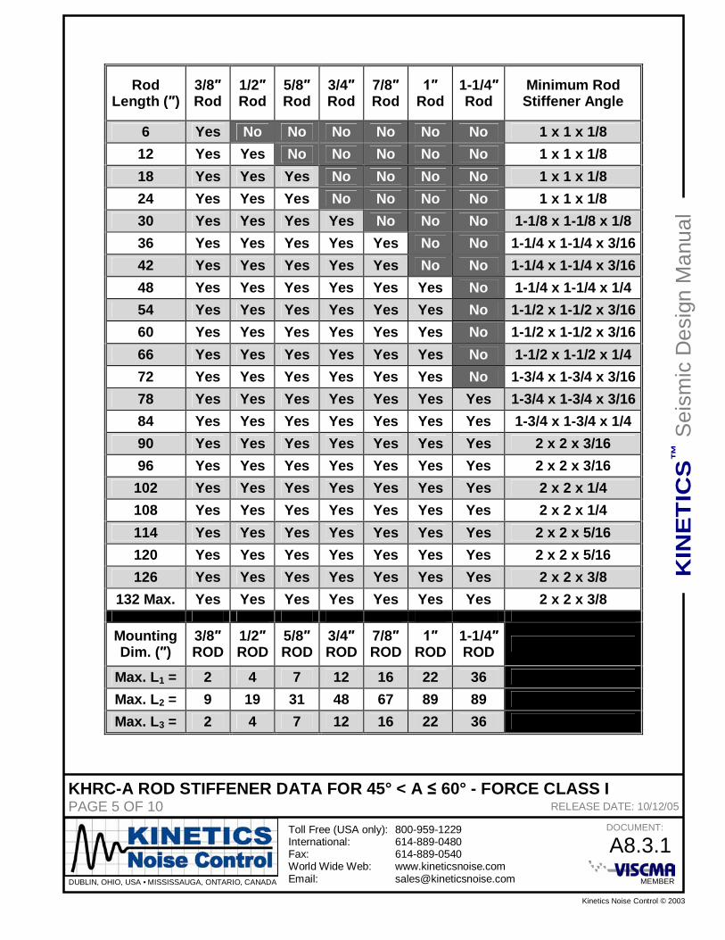
KHRC-A ROD STIFFENER DATA FOR 45° < A 60° - GENERALPAGE 1 OF 10 RELEASE DATE: 10/12/05
KHRC-A Rod Stiffener Data for 45° < A 60°
Introduction:
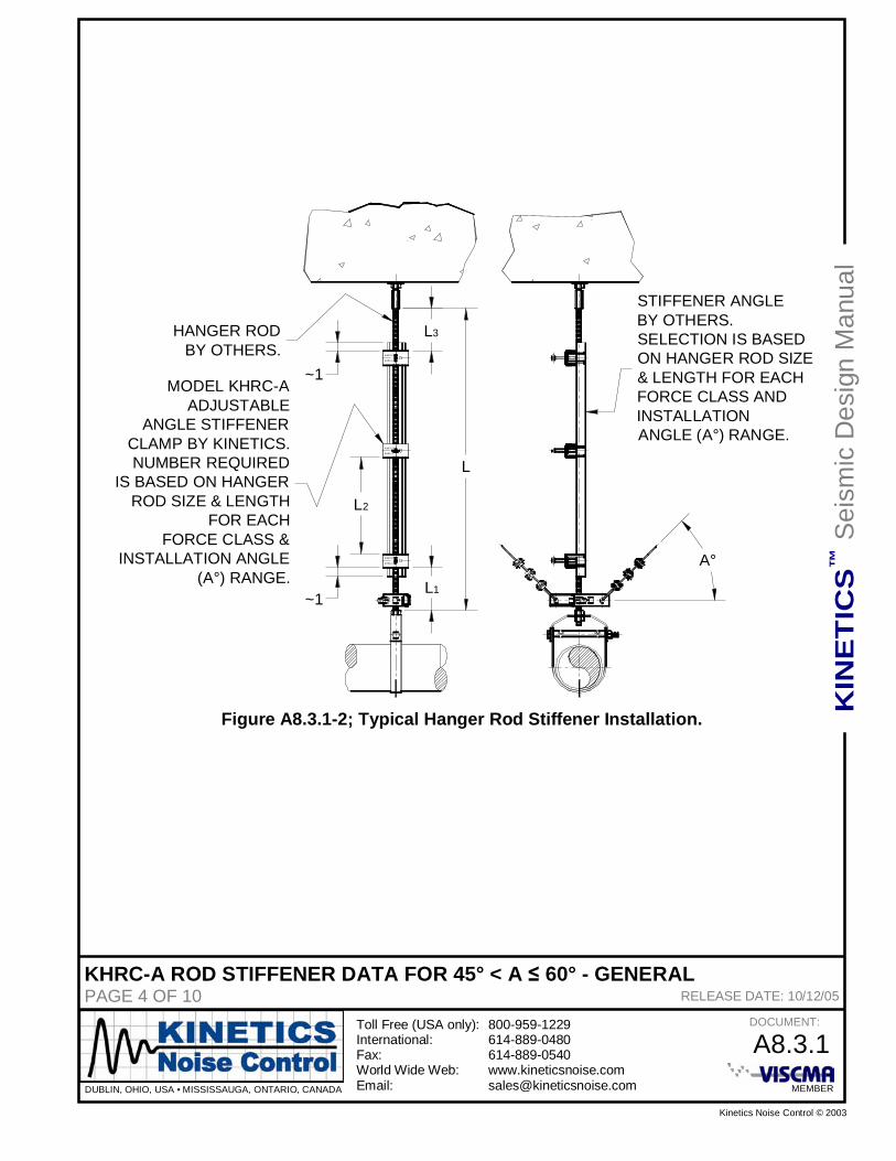
This document will aid the designer in determining if hanger rod reinforcement, rodstiffeners, will be required for a given application. If they are required, recommendationsfor a minimum stiffener size will be made. Also, rod stiffener clamp locations and spacingwill be made based on the use of Kinetics Noise Control model KHRC-A AdjustableAngle Stiffener Kit. This kit is a single clamp system that is shown in Figure A8.3.1-1. Onekit will be required for each clamp location. A minimum of two clamp kits will be requiredfor each hanger rod stiffener. The clamps and rod stiffener are assembled to the hangerrod as shown in Figure A8.3.1-2. The dimensions shown as L1, L2, and L3 are themaximum allowable installation dimensions for locating and spacing the KHRC-A clampkits.
Buckling Analysis:
Buckling failure is a catastrophic form of failure that occurs at stresses that are muchlower that those required to yield the material. It is more of a function of the geometry ofthe components than it is a function of the material. In general it is very difficult to predictthe onset of buckling. Thus, the approach used in this document will of necessity be veryconservative. All of the basic assumptions described below will lead to a conservativeresult.
There are many theories that address buckling In general there are long, intermediate,and short columns. For long columns, Euler’s formula is most often used with goodresults. For intermediate and short columns, there are many different approaches thatwould result in many iterative calculations for each case to be investigated. In order toprovide reliable results with reasonable time expenditures, Euler’s formula was used wasused to determine the maximum un-reinforced hanger rod length. The hanger rods weremodeled as having one end free, and one end fixed. If reinforcement was required for thehanger rod, it was selected based on the assumptions that the reinforcing angle wascarrying the entire compressive load, and that the reinforcing angle was equal to thelength of the hanger rod.
In a similar fashion, Euler’s formula was used to determine the maximum allowable valuesfor the clamp locating dimensions L1 and L3. However, in this case L1 and L3 assumed tobe equal to each other, and their sum was set to be equal to the maximum un-reinforcedlength of the hanger rod computed using Euler’s formula with one end of the rod fixed andthe other end free. In determining the maximum value for the clamp spacing, L2, Euler’sformula was used assuming that both ends of the hanger rod were fixed at the clamps.
The horizontal seismic loads applied to the hanger rods are based on the Kinetics NoiseControl Horizontal Force Class, or Force Class, designations of I through VI. The
KHRC-A ROD STIFFENER DATA FOR 45° < A 60° - GENERALPAGE 2 OF 10 RELEASE DATE: 10/12/05
installation angle (A), as measured from the horizontal, was taken to be 60°, and will beused to cover the range of installation angles from 46° to 60° inclusively. The Force Classsystem ranges are shown below.
Force Class I: 0 lbs through 250 lbsForce Class II: 251 lbs through 500 lbsForce Class III: 501 lbs through 1,000 lbsForce Class IV: 1,001 lbs through 2,000 lbsForce Class V: 2,001 lbs through 5,000lbsForce Class VI: 5,001 lbs through 10,000lbs
The maximum load in each Force Class was used with a Factor of Safety of 2:1 indetermining the maximum un-reinforced hanger rod length, the minimum angle size to beused for the rod stiffener, and the values used for L1, L2, and L3.
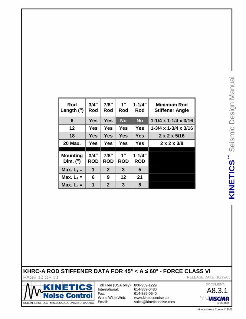
Use of the KHRC-A Rod Stiffener Data Tables:1.) Data Tables: There is a hanger rod stiffener selection data table for each Force
Class.2.) Hanger Rod Sizes: The hanger rod sizes that may be used with the Kinetics
Noise Control model KHRC-A, and that are applicable for each Force Class arelisted across the top of each data table.
3.) Hanger Rod Length: The hanger rod lengths that are applicable are listed in theleft hand column of each table in and 12 multiples. The maximum reinforcedhanger rod length for each Force Class is the last entry in this column.
4.) Rod Stiffener Requirement: Determine the appropriate Force Class for theapplication. Select the column for the hanger rod size being used, and follow itdown to the hanger rod length being considered. If the word “Yes” is found in thisbox, a hanger rod stiffener will be required. If, on the other hand, the word “No” isfound in the box, then a hanger rod stiffener is not required. If the hanger rodlength being used falls in between two of the tabulated rod lengths, use the largervalue for the hanger rod length.
5.) Minimum Stiffener Angle Size: The minimum reinforcement angle size for eachhanger rod length in each Force Class is listed in the right hand column of eachtable. Use the minimum Stiffener Angle size that corresponds to the hanger rodlength used in step “4.)”.
6.) Maximum Installation Dimensions: The maximum allowable installationdimensions, L1, L2, and L3, are tabulated by hanger rod size beneath the rodstiffener selection data table for each Force Class.
7.) KHRC-A Clamp Kits: A minimum of two (2) Kinetics Noise Control modelKHRC-A clamps kits are required for each hanger rod stiffener installation. TheKHRC-A clamp kits should be spaced approximately from each end of the rodstiffener angle. The distance from where the hanger rod is attached to thesuspended component and the lower KHRC-A clamp kit must not exceed the valuefor L1 listed for the Force Class and hanger rod size being used. If the spacing
KHRC-A ROD STIFFENER DATA FOR 45° < A 60° - GENERALPAGE 3 OF 10 RELEASE DATE: 10/12/05
between the two KHRC-A clamp kits exceeds the value of L2, maximum allowablespacing between clamps, listed for the Force Class and rod size for the application,another KHRC-A clamp kit must be added between the original pair. Finally, thedistance from the upper KHRC-A clamp kit where the hanger rod attaches to thestructure, or isolation hanger, must not exceed the value listed for L3, based on theForce Class and rod size being considered. Also note that the thumb screw shouldbe securely tightened. Pliers may be used after thumb screw is made finger tight.
KHRC-A ROD STIFFENER DATA FOR 45° < A 60° - FORCE CLASS IPAGE 5 OF 10 RELEASE DATE: 10/12/05
RodLength ( )
3/8Rod
1/2Rod
5/8Rod
3/4Rod
7/8Rod Rod
1-1/4Rod
Minimum RodStiffener Angle
6 Yes No No No No No No 1 x 1 x 1/812 Yes Yes No No No No No 1 x 1 x 1/818 Yes Yes Yes No No No No 1 x 1 x 1/824 Yes Yes Yes No No No No 1 x 1 x 1/830 Yes Yes Yes Yes No No No 1-1/8 x 1-1/8 x 1/836 Yes Yes Yes Yes Yes No No 1-1/4 x 1-1/4 x 3/1642 Yes Yes Yes Yes Yes No No 1-1/4 x 1-1/4 x 3/1648 Yes Yes Yes Yes Yes Yes No 1-1/4 x 1-1/4 x 1/454 Yes Yes Yes Yes Yes Yes No 1-1/2 x 1-1/2 x 3/1660 Yes Yes Yes Yes Yes Yes No 1-1/2 x 1-1/2 x 3/1666 Yes Yes Yes Yes Yes Yes No 1-1/2 x 1-1/2 x 1/472 Yes Yes Yes Yes Yes Yes No 1-3/4 x 1-3/4 x 3/1678 Yes Yes Yes Yes Yes Yes Yes 1-3/4 x 1-3/4 x 3/1684 Yes Yes Yes Yes Yes Yes Yes 1-3/4 x 1-3/4 x 1/490 Yes Yes Yes Yes Yes Yes Yes 2 x 2 x 3/1696 Yes Yes Yes Yes Yes Yes Yes 2 x 2 x 3/16
102 Yes Yes Yes Yes Yes Yes Yes 2 x 2 x 1/4108 Yes Yes Yes Yes Yes Yes Yes 2 x 2 x 1/4114 Yes Yes Yes Yes Yes Yes Yes 2 x 2 x 5/16120 Yes Yes Yes Yes Yes Yes Yes 2 x 2 x 5/16126 Yes Yes Yes Yes Yes Yes Yes 2 x 2 x 3/8
KHRC-A ROD STIFFENER DATA FOR 45° < A 60° - FORCE CLASS IIPAGE 6 OF 10 RELEASE DATE: 10/12/05
RodLength ( )
3/8Rod
1/2Rod
5/8Rod
3/4Rod
7/8Rod Rod
1-1/4Rod
Minimum RodStiffener Angle
6 Yes No No No No No No 1 x 1 x 1/812 Yes Yes Yes No No No No 1 x 1 x 1/818 Yes Yes Yes Yes No No No 1 x 1 x 1/824 Yes Yes Yes Yes No No No 1-1/4 x 1-1/4 x 3/1630 Yes Yes Yes Yes Yes No No 1-1/4 x 1-1/4 x 3/1636 Yes Yes Yes Yes Yes Yes No 1-1/4 x 1-1/4 x 1/442 Yes Yes Yes Yes Yes Yes No 1-1/2 x 1-1/2 x 3/1648 Yes Yes Yes Yes Yes Yes No 1-1/2 x 1-1/2 x 1/454 Yes Yes Yes Yes Yes Yes Yes 1-3/4 x 1-3/4 x 3/1660 Yes Yes Yes Yes Yes Yes Yes 1-3/4 x 1-3/4 x 1/466 Yes Yes Yes Yes Yes Yes Yes 2 x 2 x 3/1672 Yes Yes Yes Yes Yes Yes Yes 2 x 2 x 1/478 Yes Yes Yes Yes Yes Yes Yes 2 x 2 x 1/484 Yes Yes Yes Yes Yes Yes Yes 2 x 2 x 5/1690 Yes Yes Yes Yes Yes Yes Yes 2 x 2 x 3/8
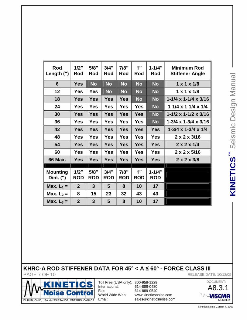
KHRC-A ROD STIFFENER DATA FOR 45° < A 60° - FORCE CLASS IIIPAGE 7 OF 10 RELEASE DATE: 10/12/05
RodLength ( )
1/2Rod
5/8Rod
3/4Rod
7/8Rod Rod
1-1/4Rod
Minimum RodStiffener Angle
6 Yes No No No No No 1 x 1 x 1/812 Yes Yes No No No No 1 x 1 x 1/818 Yes Yes Yes Yes No No 1-1/4 x 1-1/4 x 3/1624 Yes Yes Yes Yes Yes No 1-1/4 x 1-1/4 x 1/430 Yes Yes Yes Yes Yes No 1-1/2 x 1-1/2 x 3/1636 Yes Yes Yes Yes Yes No 1-3/4 x 1-3/4 x 3/1642 Yes Yes Yes Yes Yes Yes 1-3/4 x 1-3/4 x 1/448 Yes Yes Yes Yes Yes Yes 2 x 2 x 3/1654 Yes Yes Yes Yes Yes Yes 2 x 2 x 1/460 Yes Yes Yes Yes Yes Yes 2 x 2 x 5/16
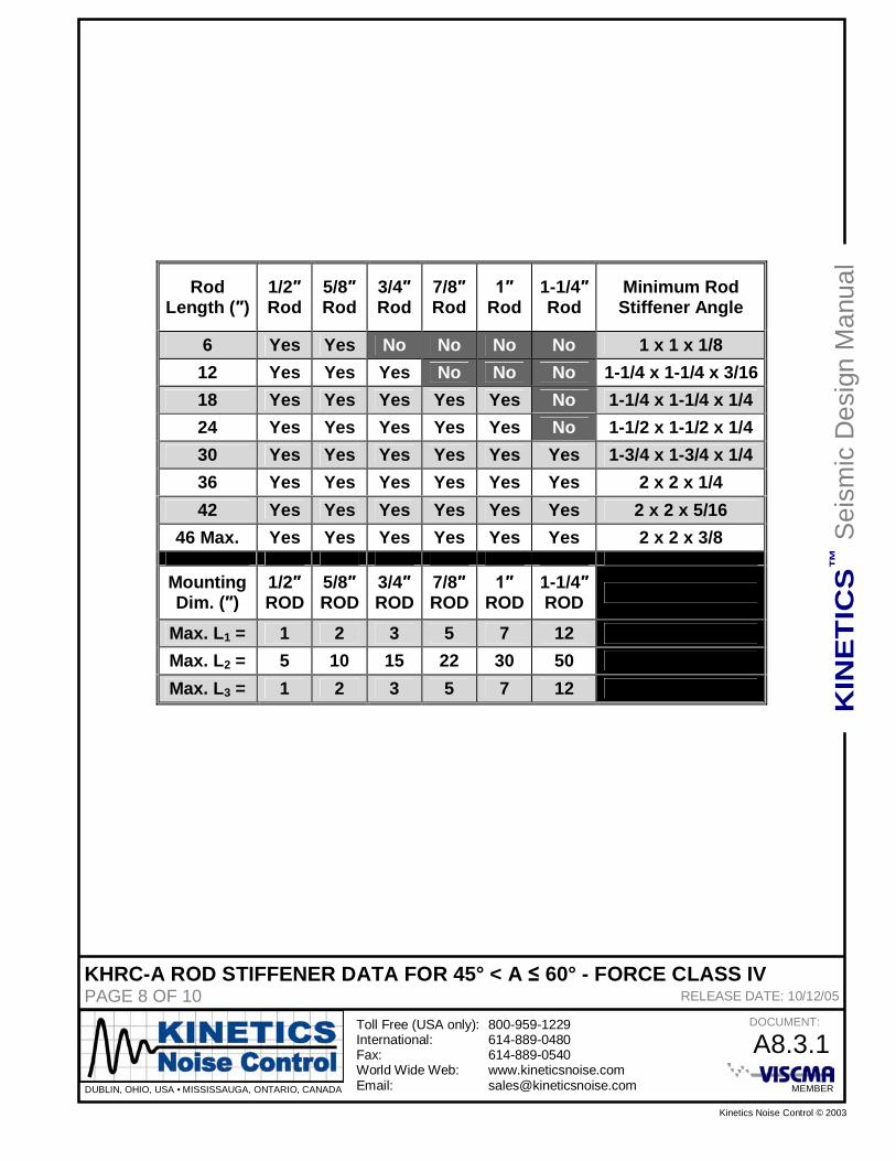
KHRC-A ROD STIFFENER DATA FOR 45° < A 60° - FORCE CLASS IVPAGE 8 OF 10 RELEASE DATE: 10/12/05
RodLength ( )
1/2Rod
5/8Rod
3/4Rod
7/8Rod Rod
1-1/4Rod
Minimum RodStiffener Angle
6 Yes Yes No No No No 1 x 1 x 1/812 Yes Yes Yes No No No 1-1/4 x 1-1/4 x 3/1618 Yes Yes Yes Yes Yes No 1-1/4 x 1-1/4 x 1/424 Yes Yes Yes Yes Yes No 1-1/2 x 1-1/2 x 1/430 Yes Yes Yes Yes Yes Yes 1-3/4 x 1-3/4 x 1/436 Yes Yes Yes Yes Yes Yes 2 x 2 x 1/442 Yes Yes Yes Yes Yes Yes 2 x 2 x 5/16
1) Determined by assuming that the conduit was a beam with fixed ends and an evenlydistributed load equal to the weight of the conduit and a 40% fill of copper. The conduitmaterial was assumed to be equal to low carbon commercial quality steel sheet with a yieldstress of 40,000 psi – 50,000 psi.
1) The Maximum Support Spacing based on Buckling relies on Euler’s Theory of ColumnBuckling. There is a Factor of Safety of 2:1 with respect to the applied Horizontal SeismicLoad. Both ends of the conduit are assumed to be fixed, and the conservative end conditionfactor of 1.00 was used.2) Horizontal Force Class I: 0 lbs. Horizontal Seismic Force 250 lbs.3) Horizontal Force Class II: 251 lbs. Horizontal Seismic Force 500 lbs.4) Horizontal Force Class III: 501 lbs. Horizontal Seismic Force 1,000 lbs.5) Horizontal Force Class IV: 1,001 lbs. Horizontal Seismic Force 2,000 lbs.6) Horizontal Force Class V: 2,001 lbs. Horizontal Seismic Force 5,000 lbs.7) Horizontal Force Class VI: 5,001 lbs. Horizontal Seismic Force 10,000 lbs.8) For Actual Horizontal Forces that fall between the minimum and maximum values for agiven Horizontal Force Class, the Maximum Support Spacing for Buckling may bedetermined by multiplying the appropriate value from Table A9.1.1-3 by the following factor.
KS = [ Upper Horizontal Force Class Limit / Actual Horizontal Seismic Force ]1/2
Example: 1/2 EMT with and Actual Horizontal Seismic Force of 50 lbs (Force Class I Range).
KS = [ 250 lbs. / 50lbs. ]1/2 = 2.24
The Actual Maximum Support Spacing = 2.24 x 4.44 ft. = 9.95 ft.
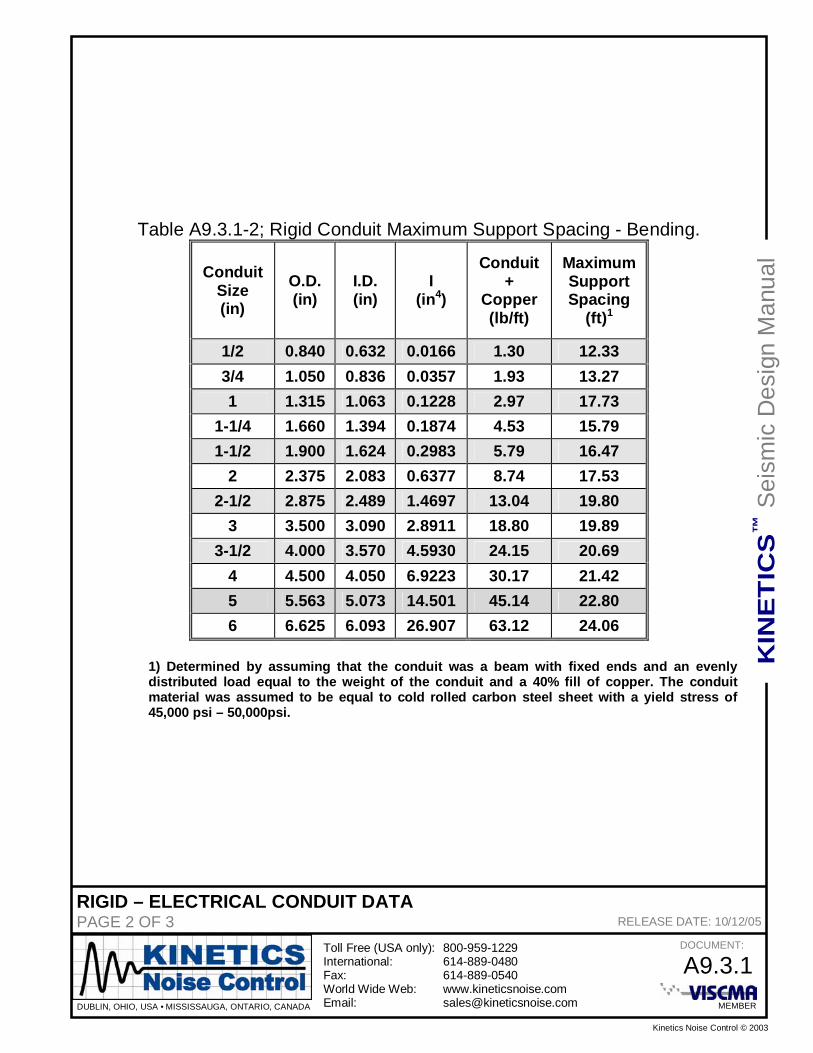
1) Determined by assuming that the conduit was a beam with fixed ends and an evenlydistributed load equal to the weight of the conduit and a 40% fill of copper. The conduitmaterial was assumed to be equal to cold rolled carbon steel sheet with a yield stress of45,000 psi – 50,000psi.
1) The Maximum Support Spacing based on Buckling relies on Euler’s Theory of ColumnBuckling. There is a Factor of Safety of 2:1 with respect to the applied Horizontal SeismicLoad. Both ends of the conduit are assumed to be fixed, and the conservative end conditionfactor of 1.00 was used.2) Horizontal Force Class I: 0 lbs. Horizontal Seismic Force 250 lbs.3) Horizontal Force Class II: 251 lbs. Horizontal Seismic Force 500 lbs.4) Horizontal Force Class III: 501 lbs. Horizontal Seismic Force 1,000 lbs.5) Horizontal Force Class IV: 1,001 lbs. Horizontal Seismic Force 2,000 lbs.6) Horizontal Force Class V: 2,001 lbs. Horizontal Seismic Force 5,000 lbs.7) Horizontal Force Class VI: 5,001 lbs. Horizontal Seismic Force 10,000 lbs.8) For Actual Horizontal Forces that fall between the minimum and maximum values for agiven Horizontal Force Class, the Maximum Support Spacing for Buckling may bedetermined by multiplying the appropriate value from Table A9.2.1-3 by the following factor.
KS = [ Upper Horizontal Force Class Limit / Actual Horizontal Seismic Force ]1/2
Example: 1/2 EMT with and Actual Horizontal Seismic Force of 50 lbs (Force Class I Range).
KS = [ 250 lbs. / 50lbs. ]1/2 = 2.24
The Actual Maximum Support Spacing = 2.24 x 4.44 ft. = 9.95 ft.
1) Determined by assuming that the conduit was a beam with fixed ends and an evenlydistributed load equal to the weight of the conduit and a 40% fill of copper. The conduitmaterial was assumed to be equal to cold rolled carbon steel sheet with a yield stress of45,000 psi – 50,000psi.
1) The Maximum Support Spacing based on Buckling relies on Euler’s Theory of ColumnBuckling. There is a Factor of Safety of 2:1 with respect to the applied Horizontal SeismicLoad. Both ends of the conduit are assumed to be fixed, and the conservative end conditionfactor of 1.00 was used.2) Horizontal Force Class I: 0 lbs. Horizontal Seismic Force 250 lbs.3) Horizontal Force Class II: 251 lbs. Horizontal Seismic Force 500 lbs.4) Horizontal Force Class III: 501 lbs. Horizontal Seismic Force 1,000 lbs.5) Horizontal Force Class IV: 1,001 lbs. Horizontal Seismic Force 2,000 lbs.6) Horizontal Force Class V: 2,001 lbs. Horizontal Seismic Force 5,000 lbs.7) Horizontal Force Class VI: 5,001 lbs. Horizontal Seismic Force 10,000 lbs.8) For Actual Horizontal Forces that fall between the minimum and maximum values for agiven Horizontal Force Class, the Maximum Support Spacing for Buckling may bedetermined by multiplying the appropriate value from Table A9.3.1-3 by the following factor.
KS = [ Upper Horizontal Force Class Limit / Actual Horizontal Seismic Force ]1/2
Example: 1/2 EMT with and Actual Horizontal Seismic Force of 50 lbs (Force Class I Range).
KS = [ 250 lbs. / 50lbs. ]1/2 = 2.24
The Actual Maximum Support Spacing = 2.24 x 4.44 ft. = 9.95 ft.