Page 1
Name: Kiomars Nassiri K. CEE 517 (Traffic Signal Systems) Term Paper UIN: 674851811 Interconnected Signals at Railroad Crossings
0 | P a g e
Kiomars Nassiri K.
UIN: 674851811
CEE 517- Traffic Signal Systems Term Paper
Spring 2015
Interconnected Signals at Railroad Crossings
Page 2
Name: Kiomars Nassiri K. CEE 517 (Traffic Signal Systems) Term Paper UIN: 674851811 Interconnected Signals at Railroad Crossings
1 | P a g e
Table of Contents
Introduction ...................................................................................................................................... 5
What are the objectives of the paper? ............................................................................................... 7
What are the important topics? ......................................................................................................... 8
Main Issues with this configuration .............................................................................................. 8
When to Preempt? ....................................................................................................................... 9
Warning time ............................................................................................................................. 10
Safety Issues with preemption system in place at intersections ................................................... 10
Track clearance time .................................................................................................................. 11
Installing Pre-signals .................................................................................................................. 11
What is the method/technique/concept behind it (them)? ............................................................... 12
Train Detection Systems ............................................................................................................. 12
Fixed Distance systems ........................................................................................................ 13
Constant warning time-controlled track circuits (CWT) .......................................................... 14
Other non-track-based systems ........................................................................................... 15
Highway-rail grade crossing warning devices and systems .......................................................... 15
Flashing Light Signals and Bells ............................................................................................ 16
Automatic Gates (Boom Barriers): ....................................................................................... 16
Other components .............................................................................................................. 17
Highway traffic signals near highway-rail grade crossings ............................................................ 17
Requirements of Interconnection ........................................................................................ 17
When to preempt traffic signals .......................................................................................... 18
Characteristics of different types of preempted signal controllers ........................................ 18
Interconnection Circuitry ..................................................................................................... 18
Preemption Phasing and Sequence: ...................................................................................... 19
Entry into preemption mode: ............................................................................................ 19
Termination of the current interval in operation (right-of-way transfer) ........................ 20
Initiation of “clear track” intervals ................................................................................ 23
1. Number of track clearance intervals ....................................................... 23
2. Track clearance signal indications displayed ........................................... 23
3. Clearance Configuration ........................................................................ 23
Page 3
Name: Kiomars Nassiri K. CEE 517 (Traffic Signal Systems) Term Paper UIN: 674851811 Interconnected Signals at Railroad Crossings
2 | P a g e
4. Duration of track clearance interval ....................................................... 24
Initiation of Preemption hold interval ........................................................................... 31
Return to normal operations ........................................................................................ 32
What are the features of the systems? ............................................................................................. 38
Fail-Safe Design ................................................................................................................... 38
Successive Operations .......................................................................................................... 39
Extended Advance Warning Times with median treatments ................................................. 39
Diagonal Railroad Crossing Both Highway Approaches to the intersection ............................ 39
Where is it implemented? ................................................................................................................ 40
What are the results from implementations? .................................................................................... 42
Changes to Access Management .......................................................................................... 42
Changes in Signal Timing ..................................................................................................... 42
Adding Turn Lanes ............................................................................................................... 42
Queue Detection ................................................................................................................. 42
Changes to Operations at Downstream Intersections ........................................................... 42
Signal Preemption ............................................................................................................... 42
Police Enforcement .............................................................................................................. 43
What are the shortcomings and limitations? .................................................................................... 44
Your ideas/suggestions for improving it (them) ................................................................................ 46
Conclusions and recommendations ................................................................................................. 47
References ...................................................................................................................................... 48
Page 4
Name: Kiomars Nassiri K. CEE 517 (Traffic Signal Systems) Term Paper UIN: 674851811 Interconnected Signals at Railroad Crossings
3 | P a g e
Table of Tables and Figures
Figure 1- Highway-rail grade crossing with nearby signalized intersection …..…………………………………..…6
Figure 2- Different types of issues with highway intersections in close vicinity of grade crossings……....8
Figure 3- Direct Current (DC) Train detection system method…………………………………………………………...13
Figure 4-Distribution of warning times by CWT systems…………………………………………………………….…...…15
Figure 5- Flashing light signal at grade crossing………………………………………………………………………………….16
Figure 6- Train demand and crossing operating indications periods……………………………………………..……20
Figure 7- Preemption Sequence for a two-phase traffic signal……………………………………………………………21
Figure 5- CAUTION—WALK TIME SHORTENED WHEN TRAIN APPROACHES sign………………………………..22
Figure 6- rail alignment crossing over two intersection approaches……………………………………………..……23
Figure 10 - Minimum track clearance distance (schematic diagram)………………………………………………….24
Figure 7 – Example Signal Preemption timeline………………………………………………………………………….……27
Table 1- Track Clearance Green Time for a Clearance Distance ‘L’ (Passenger Cars Only)…………………..28
Table 2- Track Clearance Green Time for a Clearance Distance ‘L’ (Passenger Cars + One Truck)……….28
Table 3-Track Clearance Green Time for a Clearance Distance ‘L’ (Passenger Cars + Two Trucks)………29
Figure 8- Train demand, crossing operating and train demand response time………………………………...29
Figure 9- train demand, crossing operating and traffic light response indications periods……………….30
Figure 12- Clearance phase……………………………………………………………………………………………………………….30
Figure 15- Changeable Message Sign and Head Signals to Restrict Turning Movements……………….……32
Figure 10- Time sequence of a grade crossing operation with preempted nearby highway crossing….33
Figure 11- Railroad crossing through the middle of a normal signalized intersection-Normal and
Preemption Phase plan…………………………………………………………………………………………………………………….34
Figure 12- Skewed Railroad Crossing two approaches near a signalized intersection-Normal and
Preemption Phase plan…………………………………………………………………………………………………………….……….35
Figure 13 – Railroad crossing on a two–lane roadway near a signalized intersection-Normal and
Preemption phase plan……………………………………………………………………………………………………………………..36
Page 5
Name: Kiomars Nassiri K. CEE 517 (Traffic Signal Systems) Term Paper UIN: 674851811 Interconnected Signals at Railroad Crossings
4 | P a g e
Figure 14- Railroad crossing on a two-lane roadway near a signalized intersection- Normal and
Preemption phase plan…………………………………………………………………………………………….………………………37
Figure 15- Example of Observed Maximum Queues and Train Crossings (0700 – 1000) at Intersection
with Queues Regularly Extending Past Railway Tracks………………………………………………………………………41
Figure 18- Sample Video Footage………………………………………………………………………………………………………41
Page 6
Name: Kiomars Nassiri K. CEE 517 (Traffic Signal Systems) Term Paper UIN: 674851811 Interconnected Signals at Railroad Crossings
5 | P a g e
Introduction
It is known that even under best circumstances, the railroad is an unforgiving environment and as a
result grade crossings per se are associated with hazards and risks due to the limitations in train’s
braking system, its high momentum, etc. As a result of that, the right-of-way is always given to
trains at grade crossings. This might be a point of confusion for drivers since in the case of roadway
signals, ROW is assigned alternately based on time or actuation [1].
Statistics show that fatalities and injuries as a result of grade crossing accidents are not that much
correlated with the population. According to a United Nations report (2000), “more people die in
grade crossing accidents each year in the United States than die in level crossing accidents in India.”
The reason behind this number is the large number of crossing in the US and US’s higher level of
motorization. Considering this fact, it’s incumbent on us to find engineering solutions for grade
crossing-related issues. [19]
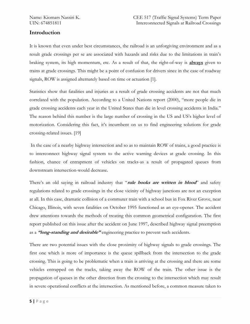
In the case of a nearby highway intersection and so as to maintain ROW of trains, a good practice is
to interconnect highway signal system to the active warning devices at grade crossing. In this
fashion, chance of entrapment of vehicles on tracks-as a result of propagated queues from
downstream intersection-would decrease.
There’s an old saying in railroad industry that “rule books are written in blood” and safety
regulations related to grade crossings in the close vicinity of highway junctions are not an exception
at all. In this case, dramatic collision of a commuter train with a school bus in Fox River Grove, near
Chicago, Illinois, with seven fatalities on October 1995 functioned as an eye-opener. The accident
drew attentions towards the methods of treating this common geometrical configuration. The first
report published on this issue after the accident on June 1997, described highway signal preemption
as a “long-standing and desirable” engineering practice to prevent such accidents.
There are two potential issues with the close proximity of highway signals to grade crossings. The
first one which is more of importance is the queue spillback from the intersection to the grade
crossing. This is going to be problematic when a train is arriving at the crossing and there are some
vehicles entrapped on the tracks, taking away the ROW of the train. The other issue is the
propagation of queues in the other direction from the crossing to the intersection which may result
in severe operational conflicts at the intersection. As mentioned before, a common measure taken to
Page 7
Name: Kiomars Nassiri K. CEE 517 (Traffic Signal Systems) Term Paper UIN: 674851811 Interconnected Signals at Railroad Crossings
6 | P a g e
mitigate safety issues as well as operational efficiency of the whole system is to coordinate railroad
warning devices with intersection traffic signals. This special type of coordination is known as
“Interconnection”. By interconnecting these signals together and defining a special operational
mode for queue clearance in highway signal controller, one can clear vehicular queues on that
segment of the road upon receiving an indication of the close proximity of trains to the crossing. So
as Marshal defines, “The objective of a preempt is to take control of the nearby traffic signal to
provide for the safe passage of a train, no matter what the status of the normal traffic signal
operation at the time the preemption occurs.”[2]
Figure 1 shows the focus area of this paper.
Figure 1- Highway-rail grade crossing with nearby signalized intersection [7] (Focus area of this paper)
Page 8
Name: Kiomars Nassiri K. CEE 517 (Traffic Signal Systems) Term Paper UIN: 674851811 Interconnected Signals at Railroad Crossings
7 | P a g e
What are the objectives of the paper?
The first and foremost goal of this paper is to give the reader an idea about the importance and
momentousness of the risks associated with grade crossings in close proximity of highway
intersections. Although ordinary people and even educated engineers have always heard about how
unsafe grade crossings can be and have a relatively good perception of the threatening dangers of
rolling stock, they have probably never thought about the potential threat from the side of nearby
highway intersections. Thus, the author of this paper has tried his best to explain this issue
thoroughly by looking at it from different aspects.
The second objective in this term paper is to help the reader understand advantages and
disadvantages of state-of-the-practice preemption and interconnection methods. This is done by
discussing features and elements of interconnecting highway traffic signal controller and the signal
system at the grade crossing. Furthermore, logic behind preemption of signal controller at the
adjacent intersection, train detection technologies, etc. is discussed.
Another more important objective of this paper is to assess other possible measures that can be
taken to tackle this problem and compare them with the focus area of this paper (interconnection of
signals). In this manner, decision makers can get familiar with different options; choose the best
available one based on their financial limitations, reliability of each measure and severity of their
specific problem and finally get the optimal result.
Page 9
Name: Kiomars Nassiri K. CEE 517 (Traffic Signal Systems) Term Paper UIN: 674851811 Interconnected Signals at Railroad Crossings
8 | P a g e
What are the important topics?
1. Main Issues with this configuration
As mentioned before, there are two potential threats from the side of adjacent highway intersections
when they are located in a short distance from railroad grade crossings. These two main issues are
classified as Type 1 and Type 2 and are defined as follows:
Type 1 (a.k.a “Influence Zone” Queue) is the queue of vehicles formed as a result of the existence
of highway intersection signal. This queue has the potential to propagate upstream and in some
cases up to the train tracks. Thus, if there’s no such preemption system in place, a train approaching
the crossing would hit the vehicle fouling the tracks since there’s no room for the entrapped vehicle
to clear train’s ROW.
Type 2 (a.k.a “Gate Spillback” Queue) is specific to the cases that we have boom gates. In this case
vehicles’ queue may extend from the crossing to the adjacent intersection, interfering with the
operation of the intersection. (Figure 1)
Figure 2- Different types of issues with highway intersections in close vicinity of grade crossings [3]
Page 10
Name: Kiomars Nassiri K. CEE 517 (Traffic Signal Systems) Term Paper UIN: 674851811 Interconnected Signals at Railroad Crossings
9 | P a g e
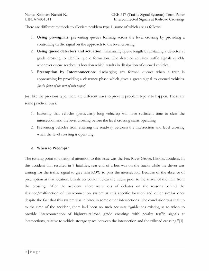
There are different methods to alleviate problem type 1, some of which are as follows:
1. Using pre-signals: preventing queues forming across the level crossing by providing a
controlling traffic signal on the approach to the level crossing.
2. Using queue detectors and actuation: minimizing queue length by installing a detector at
grade crossing to identify queue formation. The detector actuates traffic signals quickly
whenever queue reaches its location which results in dissipation of queued vehicles.
3. Preemption by Interconnection: discharging any formed queues when a train is
approaching by providing a clearance phase which gives a green signal to queued vehicles.
[main focus of the rest of this paper]
Just like the previous type, there are different ways to prevent problem type 2 to happen. These are
some practical ways:
1. Ensuring that vehicles (particularly long vehicles) will have sufficient time to clear the
intersection and the level crossing before the level crossing starts operating.
2. Preventing vehicles from entering the roadway between the intersection and level crossing
when the level crossing is operating.
2. When to Preempt?
The turning point to a national attention to this issue was the Fox River Grove, Illinois, accident. In
this accident that resulted in 7 fatalities, rear-end of a bus was on the tracks while the driver was
waiting for the traffic signal to give him ROW to pass the intersection. Because of the absence of
preemption at that location, bus driver couldn’t clear the tracks prior to the arrival of the train from
the crossing. After the accident, there were lots of debates on the reasons behind the
absence/malfunction of interconnection system at this specific location and other similar ones
despite the fact that this system was in place in some other intersections. The conclusion was that up
to the time of the accident, there had been no such accurate “guidelines existing as to when to
provide interconnection of highway-railroad grade crossings with nearby traffic signals at
intersections, relative to vehicle storage space between the intersection and the railroad crossing.”[1]
Page 11
Name: Kiomars Nassiri K. CEE 517 (Traffic Signal Systems) Term Paper UIN: 674851811 Interconnected Signals at Railroad Crossings
10 | P a g e
As an aftermath of this deathly collision, Manual on Uniform Traffic Control Devices (MUTCD) is
now giving some guidelines about the places that railroad engineers and traffic engineers should
work together to interconnect these traffic signals.
3. Warning time
Another important note about grade crossings is the amount of time needed for the preemption
process to successfully clear the tracks before the arrival of the train on grade crossing. According to
the Code of Federal Regulations, minimum amount of warning time to the roadway users should
be 20 s before the train arrives at the intersection [8]. In order to provide drivers with this minimum
time, we need to have train detectors placed far enough; at least this distance from the crossing
should be equal to the distance traversed by the fastest moving train on that line to be on the safe
side. It should be noted that this amount of time is mentioned as a minimum and whenever advance
preemption is needed, engineers might come up with a larger amount of warning time.
4. Safety Issues with preemption system in place at intersections
As it is going to be discussed in the next topic, traffic controllers that have preemption capabilities
should have at least two sets of phase plans:
A normal set that the controller is permitted to run when there is no train demand.
A train demand phase set when there is a train demand. (Clearance mode)
Now another important topic is the way controller makes a transition from normal mode to
clearance mode. This might be challenging and can increase the risks to pedestrians and roadway
traffic at the intersection who are not expecting their green phases to be abruptly terminated with no
apparent cause at the time (Trains are typically out of sight at that moment). According to MUTCD,
whenever preemption is needed, controllers can shorten pedestrian clearance phase but they’re not
allowed to reduce time requirements of Yellow and All-Red intervals [4]. However, it’s not always
the best practice to jeopardize pedestrian’s safety because of preemption. Whenever it’s inevitable,
some other measures should be taken so as not to threaten lives of pedestrians.
5. Track clearance time
The most important reason of adding a preemption system to the existing signal system is to make
sure that the queues on tracks are cleared before the arrival of trains at crossings. By taking this
Page 12
Name: Kiomars Nassiri K. CEE 517 (Traffic Signal Systems) Term Paper UIN: 674851811 Interconnected Signals at Railroad Crossings
11 | P a g e
objective into account, we should be able to estimate the required track clearance time. Constituents
of track clearance time are Startup delay and Repositioning time and they’re going to be discussed
later on. [5]
6. Installing Pre-signals
Installing pre-signals are another safety layer on top of all the other measures taken to enhance
safety on grade crossings. These signals are installed in front of railroad warning devices and are
somehow coordinated with highway signals. The objective behind installing pre-signals is the same
as interconnection and is nothing but preventing vehicles form queuing across the grade crossing.
[6] These signals should display red while the grade crossing warning devices are operating. [17]
Page 13
Name: Kiomars Nassiri K. CEE 517 (Traffic Signal Systems) Term Paper UIN: 674851811 Interconnected Signals at Railroad Crossings
12 | P a g e
What is the method/technique/concept behind it (them)?
Before starting, it seems helpful to provide the reader with a clear definition of the most important
terms of this paper: preemption and interconnection. USDOT defines these two terms as follows:
Preemption: Transfer of normal operation of traffic signals to a special control mode.
Interconnection: Electrical connection between the railroad active warning system and the traffic
signal controller assembly for the purpose of preemption. [9]
Four important components of preemption system are:
1. Train Detection Systems;
2. Highway-rail grade crossing warning devices and systems;
3. Highway traffic signals near highway-rail grade crossings; and
4. Interconnection of highway-rail grade crossing warning/control systems and highway traffic
signals
These components are going to be discussed respectively.
Train Detection Systems
In order to be able to preempt traffic signals, we should be able to detect trains well before the time
they reach crossings. Thus we need to know about existing train detection systems. Researchers have
named five different track-based train detection systems that are in use throughout the country:
1. Direct current (DC) or alternating current (AC) track circuits
2. AC-DC track circuits
3. Audio Frequency Overlay (AFO) track circuits
4. Motion sensor-controlled track circuits1
5. Constant warning time-controlled track circuits also called grade crossing predictors1 [7]
1 Most Commonly used
Page 14
Name: Kiomars Nassiri K. CEE 517 (Traffic Signal Systems) Term Paper UIN: 674851811 Interconnected Signals at Railroad Crossings
13 | P a g e
Fixed Distance systems
The first three systems are known as fixed distance systems. They are somehow modified versions
of the conventional train circuit invented by Dr. Robinson in 19th century. The concept behind their
system is to take advantage of existence of conductor steel rails and use them as a part of energized
electric circuit. When trains are approaching crossings, they shunt these circuits, activating grade
crossing warning systems. These fixed distance systems are used all over the train network so in
order to construct a specific grade crossing circuit, we should use insulated joints. In railroad
terminology, an insulated joint is the border of two adjacent train circuits. (Figure 3)
Figure 3- Direct Current (DC) Train detection system method [7]
Page 15
Name: Kiomars Nassiri K. CEE 517 (Traffic Signal Systems) Term Paper UIN: 674851811 Interconnected Signals at Railroad Crossings
14 | P a g e
In order to be able to give sufficient warning time to the crossing users, we should account for the
fastest train operating on the track(s) so as to extend the track circuit to a distance that the fastest
train would travel within that required warning time (at least 20 seconds and in case of advance
preemption more than that). This distance can be calculated with the following simple equation:
df=rf×MWT (Eq. 1)
Where:
df= approach circuit distance for the fastest train operating on the track
rf= fastest allowable train speed for the track in question
MWT= minimum warning time provided to crossing users [1]
In railroad industry we have a vast range of speeds of rolling stock from 10 to more than 110 miles
per hour, so the most significant and also the most obvious problem with this system is when slow-
moving trains are going to use the crossing. In these cases, 20 seconds warning time would increase
to sometimes more than a minute. By taking the time it takes for the train to completely pass the
crossing into consideration, roadway users may suffer more than 4 to 5 minutes of delay which is
absolutely not a desirable thing to happen.
Constant warning time-controlled track circuits (CWT)
These systems which are also known as grade crossing predictors are somehow modified and more
adaptive versions of fixed distance systems. The difference is that although they also used track
circuits for train detection, they continuously and while train is moving, measure train’s speeds and
predict the arrival time of the train at grade crossing based on that.
Page 16
Name: Kiomars Nassiri K. CEE 517 (Traffic Signal Systems) Term Paper UIN: 674851811 Interconnected Signals at Railroad Crossings
15 | P a g e
Figure 4-Distribution of warning times by CWT systems [7]
Other non-track-based systems
In the advent of advancements in technology in the new millennium, different methods of accurate
keeping track of moving stuff have evolved from which we can mention GPS tracking system. By
using these new systems, reliability of the whole detection system enhances and trains can be located
while they’re moving more precisely.
Highway-rail grade crossing warning devices and systems
In order to be able to explain interconnection and preemption methods, first we need to get familiar
with some definitions that are going to be used throughout the paper. Since this traffic-related
problem is on the interface of highway and Rail, the first thing we need to know is railroad industry’s
terminology.
There are two types of grade crossings which are classified by their distinct warning systems. The
most common type, which is called Passive grade crossing, is only equipped with signs and possibly
pavement markings. These warning devices just indicate the existence of a railroad crossing and will
not give any further information about the proximity of trains. The most important issue with these
low-cost crossings is that decision making on whether to pass the crossing or not is open to the
drivers’ discretion. The other type, Active grade crossing, has flashing lights and sometimes gates
Page 17
Name: Kiomars Nassiri K. CEE 517 (Traffic Signal Systems) Term Paper UIN: 674851811 Interconnected Signals at Railroad Crossings
16 | P a g e
and/or bells. The flashing light is used to give drivers a notification of the proximity of a train to the
crossing. They are resting in inactive state when there’s no train in close proximity of the crossing
until train reaches a certain point [7].
It should be noted that preemption system and circuitry can only be installed when grade crossing is
equipped with active warning devices.
Since the focus of this paper is interconnection between highway traffic signals and active grade
crossing warning devices, some types of these warning devices at grade crossings are going to be
introduced:
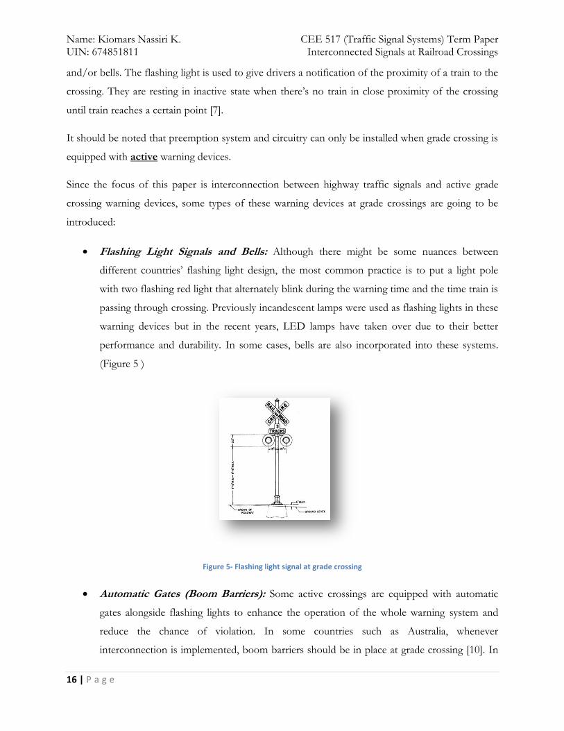
Flashing Light Signals and Bells: Although there might be some nuances between
different countries’ flashing light design, the most common practice is to put a light pole
with two flashing red light that alternately blink during the warning time and the time train is
passing through crossing. Previously incandescent lamps were used as flashing lights in these
warning devices but in the recent years, LED lamps have taken over due to their better
performance and durability. In some cases, bells are also incorporated into these systems.
(Figure 5 )
Figure 5- Flashing light signal at grade crossing
Automatic Gates (Boom Barriers): Some active crossings are equipped with automatic
gates alongside flashing lights to enhance the operation of the whole warning system and
reduce the chance of violation. In some countries such as Australia, whenever
interconnection is implemented, boom barriers should be in place at grade crossing [10]. In
Page 18
Name: Kiomars Nassiri K. CEE 517 (Traffic Signal Systems) Term Paper UIN: 674851811 Interconnected Signals at Railroad Crossings
17 | P a g e
its basic form, it is comprised of a pivoted bar named gate arm and a drive mechanism which
blocks vehicle access through the level crossing. Although it’s not solid enough to block
vehicles’ route and vehicles can pass the crossing by breaking the arm, research has shown
that these arms are very effective in reducing crossing violations. [11].
Four-quadrant gates are the most recent version of boom barriers for protecting a
grade crossing. In this configuration, the same mechanism is applied for both
directions and in both sides of the crossing. One of the major drawbacks of this
system is the possibility of entrapment of vehicles between the gates. In order to
address this issue, several ways have been proposed, the most common of which is
delaying the downward motion of exit gates for 5-7 seconds. [7]
Other components: Other components of active grade crossings such as event recorders,
signs, etc. are less important in this case and are not going to be discussed here.
In order to give highway signals an indication that warning devices at grade crossing are operating, a
signal name crossing operating is sent from these devices to traffic signal controller. This signal
starts when crossing warning lights start flashing and ends when the warning lights stop flashing.
[17]
Highway traffic signals near highway-rail grade crossings
Whenever there’s a chance for the queue of stopped vehicles waiting at an intersection traffic signal
to extend to the adjacent highway-rail grade crossing, special features should be considered to be
added to these traffic signals. This added feature, called signal preemption, would be made possible
with signal interconnection. As a result of deploying this system, vehicles trapped on the grade
crossing tracks would be given a chance to clear the track prior to the arrival of the nearby trains.
As mentioned before, the main issue with intersections near grade crossings is the possibility of
queue spillback to both junctions that will either compromise safety of grade crossing users or will
interfere with the operation of highway intersection.
Requirements of Interconnection: There are two main requirements that each preemption system
at intersections near grade crossings shall follow:
i. To provide enough time for the entrapped cars to clear the tracks prior to the arrival
of the next train at the crossing.
Page 19
Name: Kiomars Nassiri K. CEE 517 (Traffic Signal Systems) Term Paper UIN: 674851811 Interconnected Signals at Railroad Crossings
18 | P a g e
ii. To prevent any other movement from intersection towards the grade crossing during
the preemption time. [12]
When to preempt traffic signals: In the latest version of MUTCD published in 2009, it is
mentioned that intersections within 200 ft. distance of grade crossings should be equipped with
preemption systems. Intersections farther than 200 ft. from crossings still should be considered as
potential threats to the safety of crossings and in order to evaluate the need for preempting those
signals, there’s a need for a detailed queuing analysis at each location. [4] Although no specific
engineering methodology is stated in the code, but there are suggestions for the factors that should
be considered such as traffic volumes, number of lanes, saturation flow rates, traffic signal timing,
vehicular arrival characteristics and vehicle type. [4]
In Canada, road/railway grade crossings technical standards and inspection, testing and
maintenance requirements (Section 15) specify that:
“The operation of traffic signals on a road approach shall be preempted by a grade crossing
warning system:
a) Where there is less than 60 m between the stop line for the traffic signals and the rail
nearest the road intersection; or
b) If it has been determined that traffic queued for the traffic signals regularly encroach
closer than 2.4 m to the rail nearest the road intersection.” [12]
Characteristics of different types of preempted signal controllers: As discussed in the class, two
of the most common signal controllers used throughout the US are Model 170 and NEMA TS2.
Model 170 has six preemption routines, two of which, RR1 and RR2, are assigned to highway-rail
grade crossing preemption [7]. TS2 controller, also, has 6 different preemption inputs which are
identified as Preempt 1 to Preempt 6. The built-in assumption in these controllers is that the first
two preemption plans are used for grade crossings but this assumption can be changed by the
programmer. It should be noted that train preemption, whatever the number is, has priority over all
other preemption routines.
Interconnection Circuitry: In order to preempt the highway signal controller, controller’s
microprocessor should get informed of the approaching trains. In order to do so, train detection
systems should be interconnected to highway signal controller’s processor via an isolated separate
preemption circuit.
Page 20
Name: Kiomars Nassiri K. CEE 517 (Traffic Signal Systems) Term Paper UIN: 674851811 Interconnected Signals at Railroad Crossings
19 | P a g e
Preemption Phasing and Sequence:
Korve (1999) proposes the following preemption sequence for all controller units:
Entry into preemption mode,
Termination of the current interval in operation (right-of-way transfer),
Initiation of “clear track” intervals,
Initiation of Preemption hold interval, and
Return to normal operations.
In the following lines, the abovementioned operational sequence is going to be discussed:
Entry into preemption mode:
In terms of reactions to preemption, there are two modes of operation namely locking and
non-locking. Non-locking system is more sophisticated and accounts for the possibility of
trains stopping after detection or changing their direction by waiting for a short time after
train demand signal being sent to their controller. If the signal persists, they start to
transition to the preemption mode. Locking systems, however, abruptly start shifting to
preemption phasing upon receiving train demand signal.
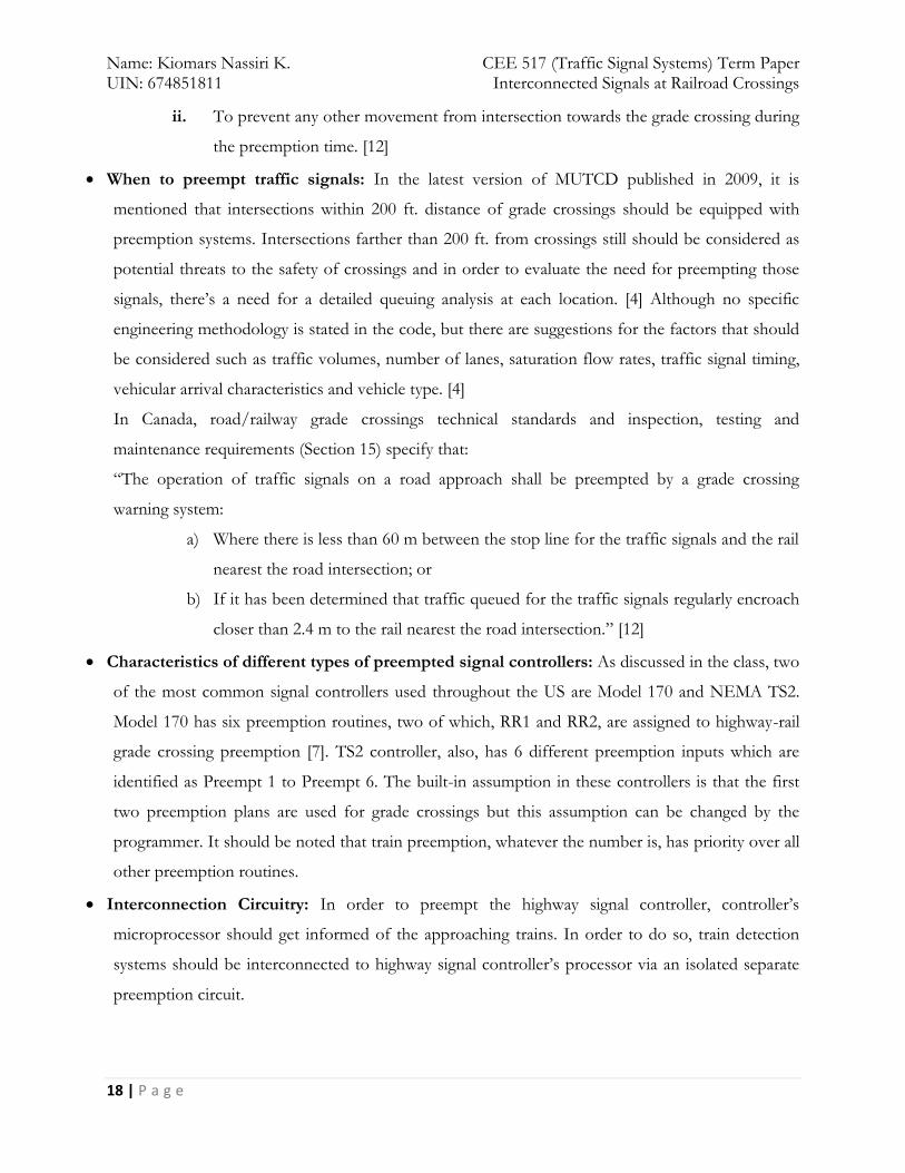
In order to enter preemption mode, a warning indication named train demand should be
sent from the train detection devices to the highway signal controller. This signal starts when
a train is detected approaching the level crossing and ends when the train has cleared the
crossing. [17]
The Train Demand has a true state (relay de-energized) from the time an approaching train is
detected until the train has cleared the level crossing. [10]
Page 21
Name: Kiomars Nassiri K. CEE 517 (Traffic Signal Systems) Term Paper UIN: 674851811 Interconnected Signals at Railroad Crossings
20 | P a g e
Figure 6- Train demand and crossing operating indications periods [17]
Termination of the current interval in operation (right-of-way transfer):
Before shifting to the track clearance interval, an important issue is truncating current
operating interval. In figure 6 this sequence is shown by letter P [7]. According to MUTCD
rules, it’s not allowed to end the ongoing phase abruptly upon getting informed of nearby
trains. The shortest time that each phase has to operate is comprised of minimum green,
yellow change and red clearance time intervals. Although it is allowed by the laws to shorten
the minimum green time, due to various safety concerns, the current practice is to have all
these three time intervals for running phases. It’s worth mentioning that the reason behind
not giving traffic engineers the authority to shorten yellow and all-red intervals is the
possibility of entrapment of cars in the intersection.
Page 22
Name: Kiomars Nassiri K. CEE 517 (Traffic Signal Systems) Term Paper UIN: 674851811 Interconnected Signals at Railroad Crossings
21 | P a g e
Figure 7- Preemption Sequence for a two-phase traffic signal [13]
An important safety-related challenge associated with preemption is the fact that it can
increase the risks to pedestrians and motorists who are not expecting their green phases to
be abruptly truncated with no apparent cause at the time. Furthermore, evaluating adequate
track clearance time precisely is not simple and is somehow be location-specific.
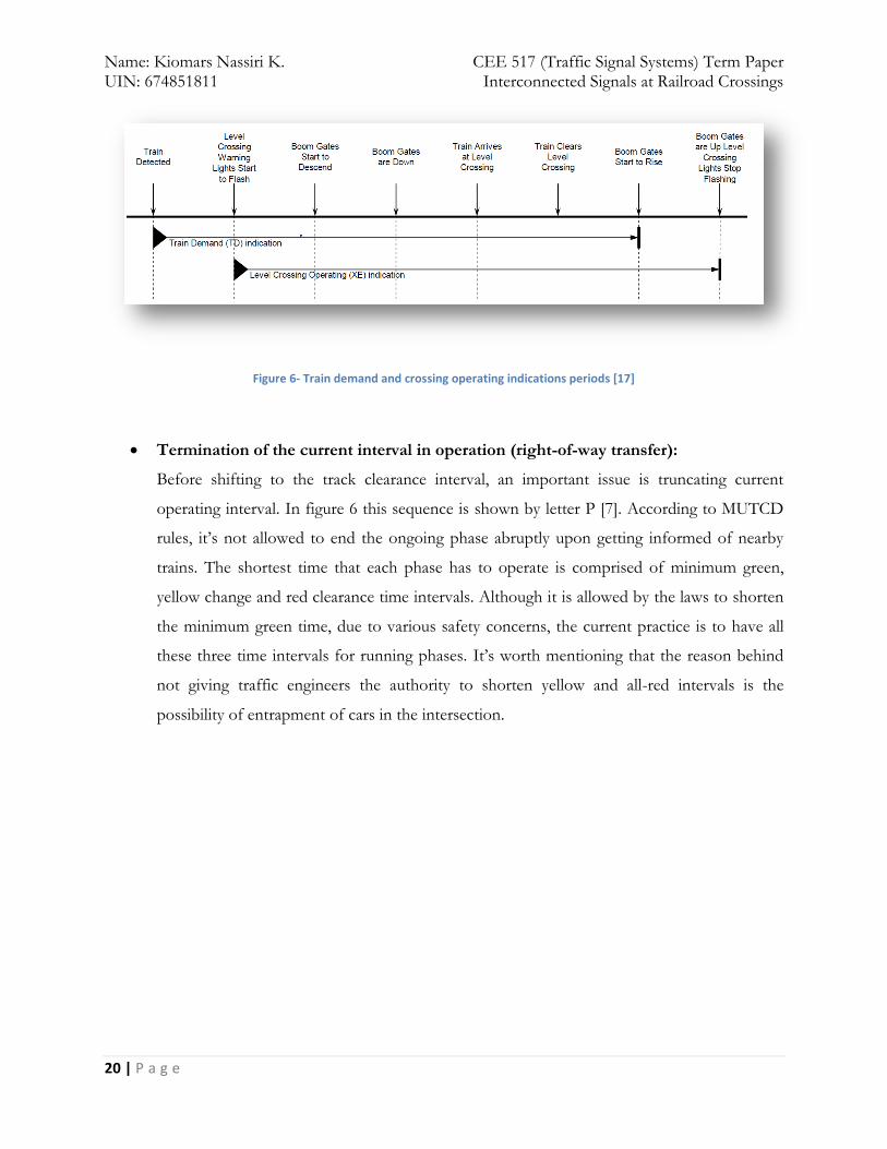
In the recent years, state DOTs are shifting gear by paying more attention to pedestrian
safety issues wherever interconnection and preemption is in place. In order to address this
problem, different measure have been taken such as train-activated signage for pedestrians
(Figure 8) and advance detection systems specifically for pedestrian clearance protection.
Page 23
Name: Kiomars Nassiri K. CEE 517 (Traffic Signal Systems) Term Paper UIN: 674851811 Interconnected Signals at Railroad Crossings
22 | P a g e
Figure 8- CAUTION—WALK TIME SHORTENED WHEN TRAIN APPROACHES sign [14]
Australian codes address this issue by allowing traffic signal controllers transition to the
preemption special mode, provided that the following safety times are observed:
o A minimum vehicle green of 5 seconds;
o Pedestrian clearance times as set;
o Yellow times as set; and
o All red times as set. [17]
Page 24
Name: Kiomars Nassiri K. CEE 517 (Traffic Signal Systems) Term Paper UIN: 674851811 Interconnected Signals at Railroad Crossings
23 | P a g e
Initiation of “clear track” intervals:
The purpose of the clearance phase is to allow vehicles that may be trapped on the level
crossing to clear the level crossing before or shortly after the warning lights start flashing
and, where there are boom gates, before the boom gates start descending. [17]
Three important points are important in this topic:
1. Number of track clearance intervals: Whenever rails cross over two different
intersection approaches (Figure 9), there’s a need for more than one clearance interval so
as to clear vehicles from both approaches separately and safely.
Figure 9- rail alignment crossing over two intersection approaches
2. Track clearance signal indications displayed: With the ability of today’s traffic
signals, traffic engineers can program signal controllers to display as many proper
indications as needed whenever they have shifted to track clearance mode. This can
incorporate right and left turn movements and has to include through movement for the
vehicles clearing the grade crossing.
3. Clearance Configuration: In order to standardize the clearance storage distance and
other clearance configurations, MUTCD in its 8th chapter defines minimum track
clearance as “the length along a highway at one or more railroad tracks, measured either
from the highway stop line, warning device, or 3.7 m (12 ft.) perpendicular to the track
centerline, to 1.8 m (6 ft.) beyond the track(s) measured perpendicular to the far rail,
along the centerline or edge line of the highway, as appropriate, to obtain the longer
Page 25
Name: Kiomars Nassiri K. CEE 517 (Traffic Signal Systems) Term Paper UIN: 674851811 Interconnected Signals at Railroad Crossings
24 | P a g e
distance.” The following schematic diagram illustrates the above definition and makes it
less vague.
The minimum track clearance distance as described before should be totally clear of any
vehicles. That is, any vehicle stopping at the grade crossing and blocking even a small
portion of this distance, should be relocated to another position completely beyond this
segment. Considering figure 10, front-end of vehicle A is within the predefined track
clearance distance and as a result it should be repositioned whenever a train is
approaching the crossing to a safer position, like vehicle B’s position.
Figure 10 - Minimum track clearance distance (schematic diagram) [15]
4. Duration of track clearance interval: The most important of all is determination of
the adequate operating time for queue clearance mode. According to MUTCD,
operation time for the grade crossing flashing lights is 20 seconds before arrival of the
train. Now the question is that if the same interconnection system is in place for traffic
light preemption, would that 20 seconds be enough for clearing the queue or not?
The common practice is that in formulation of the queue clearance time traffic engineers
should account for the following aspects:
• Grade crossing user vehicle types, e.g. cars, vans, single-unit trucks, etc;
Page 26
Name: Kiomars Nassiri K. CEE 517 (Traffic Signal Systems) Term Paper UIN: 674851811 Interconnected Signals at Railroad Crossings
25 | P a g e
• Distance between the grade crossing and the intersection; and
• Geometry/layout of the intersection, e.g. pavement type, horizontal alignment,
vertical grades. [17]
Among all the other efforts to quantify required clearance time, Gary Long has done an
extensive analytical research on this topic. He believes that “While 20 sec might be
adequate for railroad tracks that are within 200 ft. of signalized roadway intersections, it
is usually grossly inadequate for separations approaching 500 ft.” [15]
Although this concern has been addressed in MUTCD by allowing an increase in the 20-
second warning time, it’s open to interpretation of traffic engineers since there’s no
specific and objective guideline on the extent of this change.
Practically speaking though, adding to the 20-second minimum warning time introduces
some other safety issues to the whole system. In this way, motorists’ delay may become
excessive tempting them to think of some risky behaviors in order to pass the crossing
whenever it’s not safe to do so. Thus, in order to properly alleviate this problem,
different types and arrangements of train detection devices will be required.
There are different definitions for clearance time of the vehicles in queue when a train is
detected to be approaching the crossing. A common practice is to split this clearance
time into two separate components:
a. Startup delay: It begins at the instant when a signal turns green allowing queued
vehicles to move, and ends at the instant when the final vehicle at risk in a queue
initiates movement. [15]
Since vehicles queueing at an intersection crossing will begin moving one
after the other, startup delay is defined so as to account for this sequential
movement.
The more vehicles are in the queue, the more startup delay the whole system
will suffer from. So what matters here is more the number of vehicles in
queue rather than the queuing distance.
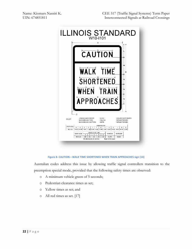
Long proposes the following equation for this delay component:
Page 27
Name: Kiomars Nassiri K. CEE 517 (Traffic Signal Systems) Term Paper UIN: 674851811 Interconnected Signals at Railroad Crossings
26 | P a g e
b. Repositioning time: It involves the time needed for the last vehicle to
accelerate from rest and travel a distance sufficient to clear the crossing. [15]
Since different types of vehicles have different acceleration methods, it’s not
possible to derive a uniform formula for all vehicle types. Long (2002) has
classified these formuli into three categories. The first case is applicable for
roadways that only passenger cars are allowed to use. In the second case,
roadways users include passenger cars, buses and single-unit trucks (combination
trucks are not allowed). The last category includes all vehicle types. Further
information about the ways these times are calculated can be found in reference
[15].
Figure 11 better illustrates the sequence of events, by showing a generalized
schematic timeline of both railroad and preemption events.
Page 28
Name: Kiomars Nassiri K. CEE 517 (Traffic Signal Systems) Term Paper UIN: 674851811 Interconnected Signals at Railroad Crossings
27 | P a g e
Figure 12 – Example Signal Preemption timeline [1]
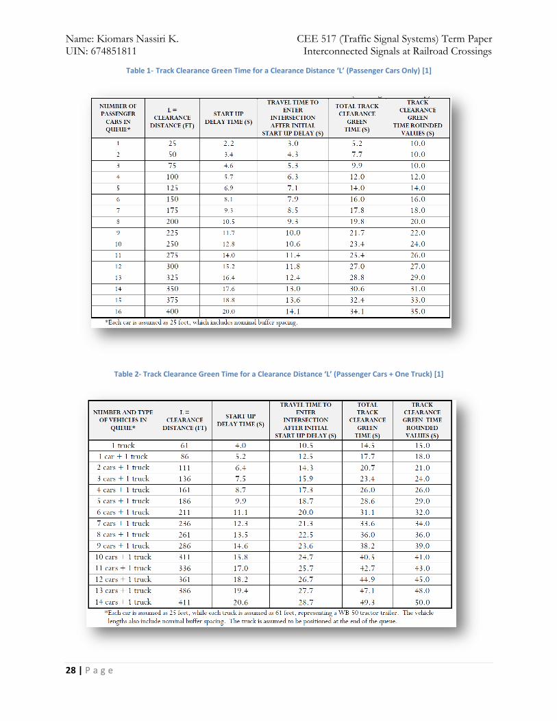
Following tables are given based on the methodology used by Long and are presenting
the total track clearance green time required to clear a queue with length ‘L’. A detailed
analysis of these tables is available in [1].
Page 29
Name: Kiomars Nassiri K. CEE 517 (Traffic Signal Systems) Term Paper UIN: 674851811 Interconnected Signals at Railroad Crossings
28 | P a g e
Table 1- Track Clearance Green Time for a Clearance Distance ‘L’ (Passenger Cars Only) [1]
Table 2- Track Clearance Green Time for a Clearance Distance ‘L’ (Passenger Cars + One Truck) [1]
Page 30
Name: Kiomars Nassiri K. CEE 517 (Traffic Signal Systems) Term Paper UIN: 674851811 Interconnected Signals at Railroad Crossings
29 | P a g e
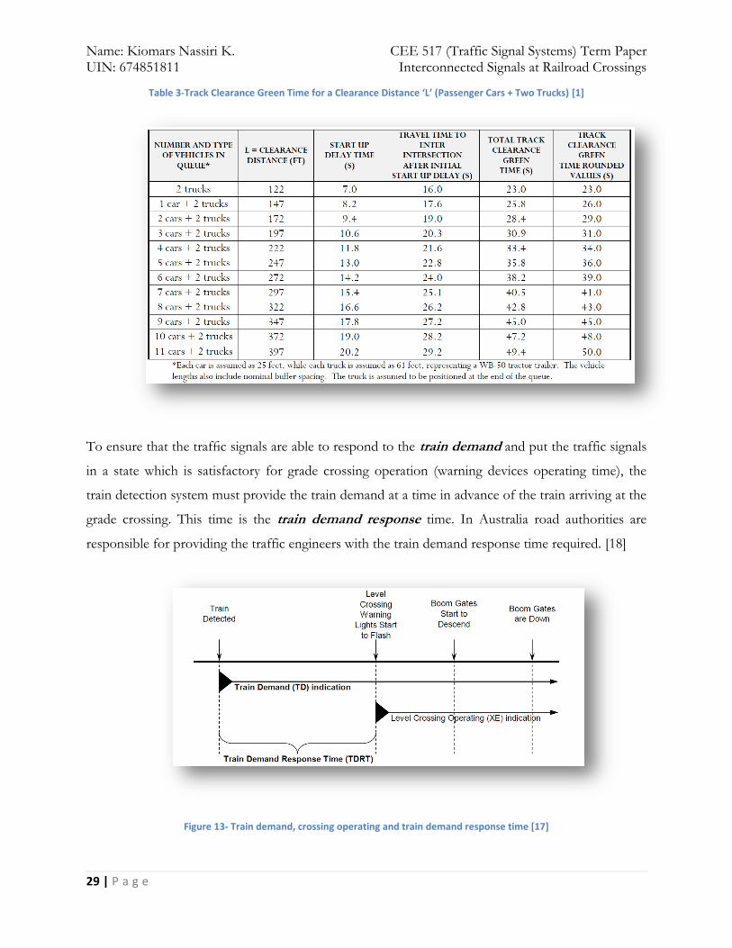
Table 3-Track Clearance Green Time for a Clearance Distance ‘L’ (Passenger Cars + Two Trucks) [1]
To ensure that the traffic signals are able to respond to the train demand and put the traffic signals
in a state which is satisfactory for grade crossing operation (warning devices operating time), the
train detection system must provide the train demand at a time in advance of the train arriving at the
grade crossing. This time is the train demand response time. In Australia road authorities are
responsible for providing the traffic engineers with the train demand response time required. [18]
Figure 13- Train demand, crossing operating and train demand response time [17]
Page 31
Name: Kiomars Nassiri K. CEE 517 (Traffic Signal Systems) Term Paper UIN: 674851811 Interconnected Signals at Railroad Crossings
30 | P a g e
Another indication that will result in efficient operation of the whole system is named traffic light
response (TLR). This signal is sent from highway traffic signal to grade crossing warning devices
when they’re in a state which is satisfactory for the level crossing to commence operation. This
indication supposedly reduces the time that warning devices need to wait before starting their
operation (train demand response time). If the TLR is not received the crossing will operate after the
Train Demand Response Time has elapsed.
Figure 14- train demand, crossing operating and traffic light response indications periods
The clearance phase may be optionally extended beyond the minimum queue clearance time to clear
all vehicles queued between the level crossing and the intersection stop line.
Figure 15- Clearance phase
Page 32
Name: Kiomars Nassiri K. CEE 517 (Traffic Signal Systems) Term Paper UIN: 674851811 Interconnected Signals at Railroad Crossings
31 | P a g e
“The level crossing boom mechanism Gate Delay is the time delay from the start of operation of
the level crossing flashing lights and bells to the boom gates commencing to descend. The gate delay
will be typically 12 seconds where ever the level crossing interfaces to the traffic signals.” [10]
Whenever there’s a chance for reformation of queues, the Clearance Phase extends beyond the start
of the level crossing flashing warning signals and concludes after the booms start to descend.
Initiation of Preemption hold interval
Intervals occurring after track clearance interval in traffic signal controller while preemption
is still in place are called Preemption Hold Intervals. During these intervals, traffic
controllers give Right-of-way to some other conflicting movements that do not conflict with
the train movement through grade crossing. Moreover, pedestrian movement directions not
conflicting with the train movement are served. There are different modes of operation for
preemption hold intervals throughout the world, some of which are going to be discussed
below:
1. All Red: during preemption hold interval with this mode of operation, all the other
intersection traffic lights will show red until train passes through the crossing. This
operating mode obviously decreases the throughput of the whole intersection but in
some cases such as places that railroad alignment is such that it crosses multiple
intersection approaches (figure 9), this is the best practice. The reason is that there may
be no other safe movement direction for vehicle’s at the intersection.
2. Flashing Red: works as if an all-way STOP sign is in place. In order to comply with the
rules, intersection users should come to a complete stop at stop line before proceeding.
This mode inhibits movements towards the railroad crossing.
3. Flashing Red/Flashing Yellow: Rules that should be abided by upon encountering these
junctions are the same as the previous one; the only difference is that vehicles on the
roadway parallel to tracks get flashing yellow sign. Thus, they do not need to come to a
complete stop at the intersection and can cautiously move forward through the
intersection.
In some cases, in order to give drivers a better understanding of the situation, some
changeable signs may be utilized. (Figure 15)
Page 33
Name: Kiomars Nassiri K. CEE 517 (Traffic Signal Systems) Term Paper UIN: 674851811 Interconnected Signals at Railroad Crossings
32 | P a g e
Figure 16- Changeable Message Sign and Head Signals to Restrict Turning Movements [1]
Return to normal operations
There are two different practices in servicing other movements after preemption phase is
passed. The first one is first returning to those traffic movements that were most delayed as
a result of preemption. The other one is first servicing those movements that have a
potential for queue spillback to other intersections downstream. The second one might be
problematic in some intersections because it may impose excessive delays to the other
movement direction that is delayed for a long time before preemption and after that.
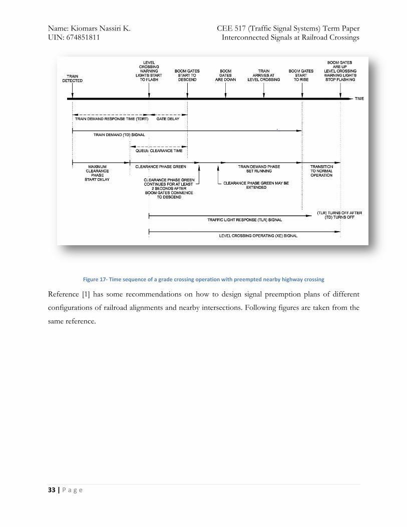
Figure 16 recaps whatever discussed previously.
Page 34
Name: Kiomars Nassiri K. CEE 517 (Traffic Signal Systems) Term Paper UIN: 674851811 Interconnected Signals at Railroad Crossings
33 | P a g e
Figure 17- Time sequence of a grade crossing operation with preempted nearby highway crossing
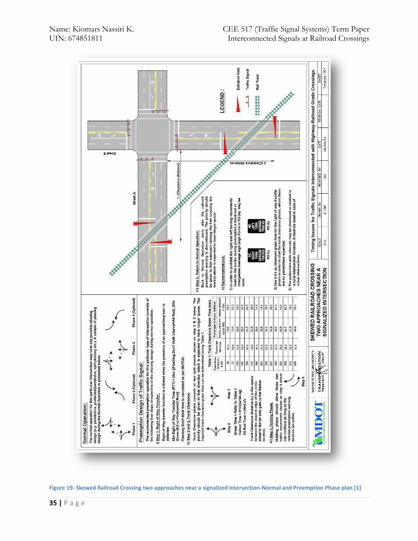
Reference [1] has some recommendations on how to design signal preemption plans of different
configurations of railroad alignments and nearby intersections. Following figures are taken from the
same reference.
Page 35
Name: Kiomars Nassiri K. CEE 517 (Traffic Signal Systems) Term Paper UIN: 674851811 Interconnected Signals at Railroad Crossings
34 | P a g e
Figure 18- Railroad crossing through the middle of a normal signalized intersection-Normal and Preemption Phase plan [1]
Page 36
Name: Kiomars Nassiri K. CEE 517 (Traffic Signal Systems) Term Paper UIN: 674851811 Interconnected Signals at Railroad Crossings
35 | P a g e
Figure 19- Skewed Railroad Crossing two approaches near a signalized intersection-Normal and Preemption Phase plan [1]
Page 37
Name: Kiomars Nassiri K. CEE 517 (Traffic Signal Systems) Term Paper UIN: 674851811 Interconnected Signals at Railroad Crossings
36 | P a g e
Figure 20 – Railroad crossing on a two–lane roadway near a signalized intersection-Normal and Preemption phase plan [1]
Page 38
Name: Kiomars Nassiri K. CEE 517 (Traffic Signal Systems) Term Paper UIN: 674851811 Interconnected Signals at Railroad Crossings
37 | P a g e
Figure 21- Railroad crossing on a two-lane roadway near a signalized intersection- Normal and Preemption phase plan [1]
Page 39
Name: Kiomars Nassiri K. CEE 517 (Traffic Signal Systems) Term Paper UIN: 674851811 Interconnected Signals at Railroad Crossings
38 | P a g e
What are the features of the systems?
Fail-Safe Design: Chris Wullems defines this concept as: “a design philosophy applied to
safety–critical systems, such that the result of a failure either prohibits the system from
assuming or maintaining an unsafe state, or causes the system to assume a state known to be
safe.” [16] In order to maintain that conditions, track circuits used for train detection and
interconnection circuits used for signal preemption should be energized when there’s no
train interfering their circuit. The approach of the train, though, should de-energize these
tracks to activate preemption mode. In this manner, whenever there’s a power failure in the
whole system, signal will be preempted.
Australian approach to fault monitoring and management is connecting traffic signal
controller to SCATS to ensure that the site is monitored and alarms notified. In this case, if
the controller finds a fault in any of the system components, it emits signals a high priority
alarm and communicates it through SCATS. The common practice in this part of the world
is that both railroad and roadway authorities should “nominate a contact person for each
crossing and establish an agreed protocol for reporting problems with the operation of either
system.” [17]
Successive Operations: Whenever there’s a possibility of trains arriving at grade crossing
with short intervals, special measures need to be considered. Three of the general cases are
discussed below:
1. The second train places a train demand while the first train demand is still in place. In
highway interconnection terminology in this stage traffic controller is blind and will not “see”
the new demand and the only thing it sees is the continuous demand. In this case, traffic
controller will remain in the special preemption mode until the demand is ended.
2. In this case the second train’s demand is sent to the controller a few seconds after grade
crossing warning devices finished their operation. In this case, the new demand is considered
as a new demand and signal controller should go through all the preemption steps.
3. The last special case is when the second demand is sent to controllers and warning devices
when the previous demand is ceased but warning devices are still operating. Now two
different scenarios apply:
Page 40
Name: Kiomars Nassiri K. CEE 517 (Traffic Signal Systems) Term Paper UIN: 674851811 Interconnected Signals at Railroad Crossings
39 | P a g e
a. The demand is received before the time that traffic signal controller is going to
remove its traffic light response. In this case, the the traffic signal controller in the
train demand phase set and remains here until “both” train demands have ceased.
b. The second train demand is received after cession of traffic light response. In this
stage the successive demand is treated as a new separate demand. [17]
To ensure correct operation of the grade crossing/traffic signal interconnection, it is a
requirement that the removal of the Train Demand is to be received by the traffic controller
prior to the ending of grade crossing’s operation. This is achieved by the grade crossing
continuing to operate until the Traffic Light Response is removed [10].
Extended Advance Warning Times with median treatments: In cases that grade
crossings are equipped with boom gates and there’s a possibility of extending warning time
to more than 45 seconds, it’s a common practice to include median treatments (such as
adding a median) so as to prevent drivers bypass the gates.
Diagonal Railroad Crossing Both Highway Approaches to the intersection: whenever
conditions of figure 9 exist, the common practice is to clear out traffic on both roadways
prior to the arrival of the train which requires approximately twice the preemption time
computed for one approach.
Page 41
Name: Kiomars Nassiri K. CEE 517 (Traffic Signal Systems) Term Paper UIN: 674851811 Interconnected Signals at Railroad Crossings
40 | P a g e
Where is it implemented?
Preempting highway signals when they’re in close proximity of grade crossings is one of the most
common solutions to the potential threat of queue accumulation between the two junctions.
Throughout the world, different countries such as Australia, Canada, United States, New Zealand,
etc. have taken this measure to mitigate this problem. An extensive study on this issue is discussed
next in which interconnection and some other alternative solutions were implemented in Canada.
(Reference [20])
This study has been done in Region of York, Ontario, Canada on queues formed at 6 signalized
intersections that appeared to be regularly extending from the traffic signals past a nearby set of
railroad tracks. According to RTD-10 (Canadian code of operation-Transport Canada), all of these
intersections should be equipped with signal preemption. This study was conducted so as to weigh
the usage of signal preemption against other feasible solutions for mitigating queues at these
junctions. It is mentioned at the report that “the purpose of this project is to present a methodology
for analyzing and characterizing queues at signalized intersections in addition to identifying
techniques for evaluating the effectiveness of potential mitigating solutions.” [20]
The first stage in this study was to gather traffic information from these intersections. In order to do
so, they used video trailers to record footage of traffic queued at intersections during the morning
and afternoon peak hours which are 5-10 and 15-19 respectively. By reviewing these video footages,
they collected some pieces of statistical information about some issues such as:
The queue lengths at the end of each signal cycle;
Traffic patterns contributing to the length of queues;
Time required for a vehicle at the end of a queue to proceed forward;
Frequency of train crossing the location and associated timing of events leading to and after
the passage of the train; and
Frequency of train crossing the location and associated timing of events leading to and after
the passage of the train.
Page 42
Name: Kiomars Nassiri K. CEE 517 (Traffic Signal Systems) Term Paper UIN: 674851811 Interconnected Signals at Railroad Crossings
41 | P a g e
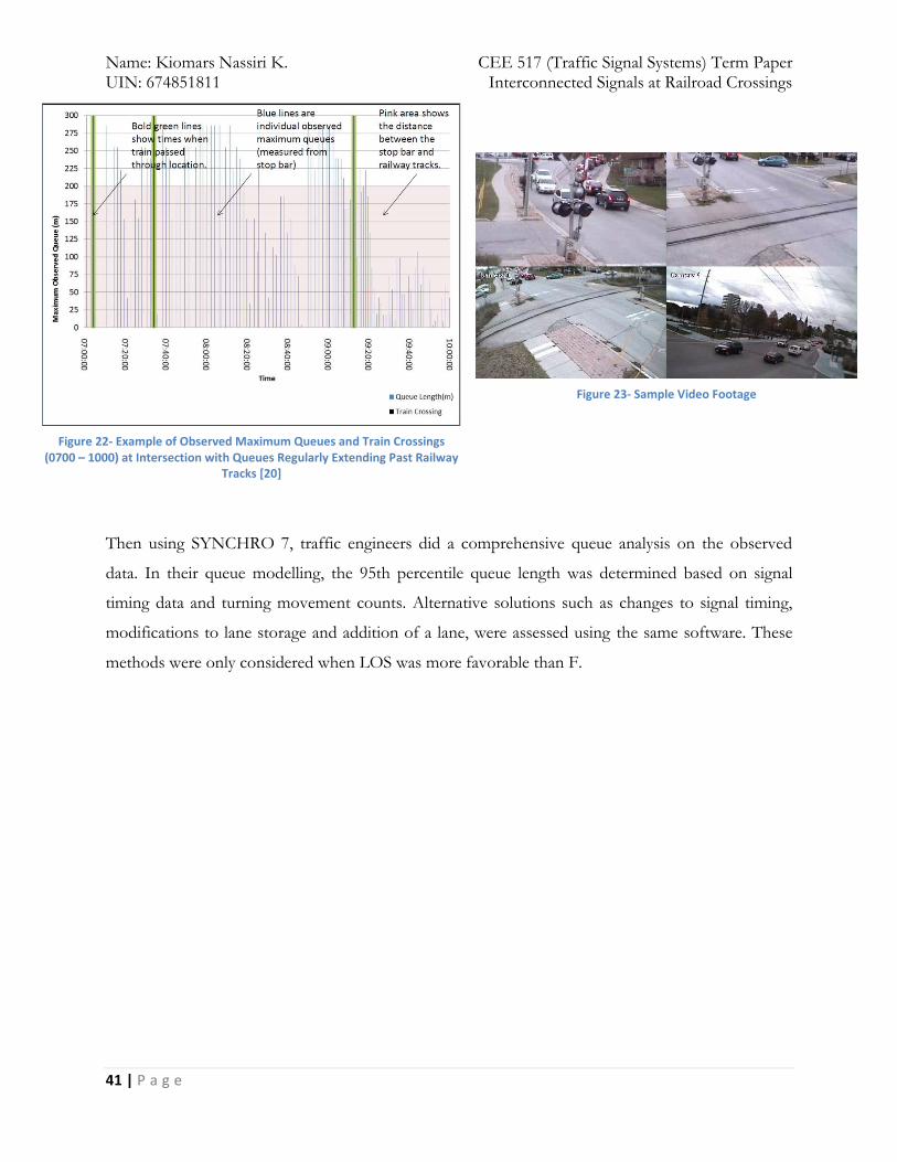
Then using SYNCHRO 7, traffic engineers did a comprehensive queue analysis on the observed
data. In their queue modelling, the 95th percentile queue length was determined based on signal
timing data and turning movement counts. Alternative solutions such as changes to signal timing,
modifications to lane storage and addition of a lane, were assessed using the same software. These
methods were only considered when LOS was more favorable than F.
Figure 22- Example of Observed Maximum Queues and Train Crossings (0700 – 1000) at Intersection with Queues Regularly Extending Past Railway
Tracks [20]
Figure 23- Sample Video Footage
Page 43
Name: Kiomars Nassiri K. CEE 517 (Traffic Signal Systems) Term Paper UIN: 674851811 Interconnected Signals at Railroad Crossings
42 | P a g e
What are the results from implementations?
7 different solutions to the aforesaid problem were found to be applicable to the 6 intersections of
interest. These resolutions are reviewed here:
1. Changes to Access Management: in some cases there were some access routes just
upstream of the railroad tracks which were one of the potential sources of traffic obstruction
at the crossing. In order to address this issue, turn or time-based restrictions were imposed
to the access routes. (An alternative for signal preemption that can be implemented in a short time frame)
2. Changes in Signal Timing: whenever LOS of the intersection was acceptable, adding to
the green time to the railroad grade crossing approach was considered. In one case,
SYNCHRO’s analysis showed a modest decrease in 95th percentile queue length. Also in
another case, left-turning vehicles were source of queue spillback. For this case, when the
protected left-turn phase was doubled, 95th percentile queue length decreased nosedived. (An
alternative for signal preemption that can be implemented in a short time frame)
3. Adding Turn Lanes: in another intersection, review of video footage was showing a high
volume of right-turning vehicles queueing at the intersection whereas there’s no separate
right-turn lane. Engineers added a hypothetical exclusive right-turn lane to the geometry of
intersection and observed an immense reduction in queue length. (A more costly alternative to
signal preemption)
4. Queue Detection: another feasible solution was putting advance queue detectors near
railroad grade crossing that could actuate traffic signal whenever a queue was forming near
crossing. (A more costly alternative to signal preemption)
5. Changes to Operations at Downstream Intersections: At two intersections, traffic from
another signalized intersection further downstream was queuing back to the traffic signals at
the study intersection. As a result, Motorists couldn’t move through the intersection during
the green phase, creating queues extending far beyond the railway tracks. A resolution to this
problem might be changes to the signal timing or geometry of downstream intersections. (A
more costly alternative to signal preemption)
6. Signal Preemption: in order to assess feasibility of signal preemption at these junctions and
determine additional time requirements for queue clearance before arrival of train, TxDOT
worksheet (prepared by the Texas Department of Transportation in the Guide for
Determining Time Requirements for Traffic Signal Preemption at Highway-Rail Grade
Page 44
Name: Kiomars Nassiri K. CEE 517 (Traffic Signal Systems) Term Paper UIN: 674851811 Interconnected Signals at Railroad Crossings
43 | P a g e
Crossings) was used. The conclusion was that only for one of the intersections, the required
additional time was reasonable (22 s) while for the other 5 intersections the additional time
was excessively long and impractical. (34-60s). The reasons that were mentioned in this
report for infeasibility of additional time requirements of those 5 intersections are as follows:
a. The greater distance between the signals and the railway tracks
b. the greater uncertainty that the queue would be completely cleared prior to the
arrival of the train; and
c. The distance upstream that the advance warning would need to be placed to activate
pre-emption at the traffic signals.
7. Police Enforcement: in intersections that video footage has shown numerous gate down
violations and unsafe driving behavior, periodic enforcement of the law by police would be
an option for a short-term period.
Page 45
Name: Kiomars Nassiri K. CEE 517 (Traffic Signal Systems) Term Paper UIN: 674851811 Interconnected Signals at Railroad Crossings
44 | P a g e
What are the shortcomings and limitations?
It is a fact that in almost all of the cases, first stage of preemption, queue clearance phase, is
wasted because rarely a crossing user stops on crossing no matter a train is approaching or
not. Albeit this fact shows the inefficiency of train preemption system, this driving behavior
seems to be adding a layer of safety to the whole process and in the first look, it might be
considered to be a positive move from safety perspective; however, even that’s not the case.
The problem is with the dynamic learning process of roadway commuters. After a while,
drivers will learn that they would suffer less delay if they take advantage of the queue
clearance mode. So whenever a train is approaching and warning devices are operating,
motorists may choose to drive recklessly so as to pass the crossing and enjoy the reduced
delay.
Moreover, the amount of incurred delay by the first stage rises whenever the distance
between two junctions increases.
As it was mentioned before, interconnection is a viable method whenever we have active
warning devices in place at grade crossings. However, majority of grade crossing in the US
are passive crossings that have no such a capability to be interconnected to the adjacent
intersection in a short time frame. As a result, this solution is not feasible for a large number
of grade crossings. In these cases, other alternative measures to signal preemption discussed
before can be evaluated and implemented. Moreover, in cases that we have nearby un-
signalized intersections with STOP and YIELD signs, interconnection cannot be used.
Fail-safe design of the whole interconnection system which seems to be the best practice is
addressing safety issues in case of failure, might inadvertently add some societal risks. There
are some drivers that lose their trust on warning devices as a result of experiencing
undesirable long false warnings at grade crossings on and on. It might be as a result of failure
in one of the components that changes the state of warning devices to their most restrictive
mode of operation. Thus, drivers might disregard these warning devices and drive through
crossings.
There are some other small issues with the current systems that my result in malfunction of the
whole system from which I can mention the following:
Page 46
Name: Kiomars Nassiri K. CEE 517 (Traffic Signal Systems) Term Paper UIN: 674851811 Interconnected Signals at Railroad Crossings
45 | P a g e
Issues with interconnection circuitry: Train detection systems connect to traffic signals through
some plug-in boards. Since there are lots of these plug-in boards inside these traffic signal
controllers, a potential issue is the confusion in determining the appropriate interface location in
case these plug-in boards are not labeled or are labeled inconsistently.
Page 47
Name: Kiomars Nassiri K. CEE 517 (Traffic Signal Systems) Term Paper UIN: 674851811 Interconnected Signals at Railroad Crossings
46 | P a g e
Your ideas/suggestions for improving it (them)
This method per se is not a guarantee for having 100% safe grade crossing. The most important
contributing factor to accidents on grade crossings is the human factor. Preemption would not work
as effective as we might think if drivers are not complying with the rules. That is, if motorists pass
the flashing-lights or bypass the boom gates, preemption cannot be helpful even if it’s perfectly
tuned. So besides working on engineering part of these geometric configurations, it’s incumbent on
us to put some time and effort to teach the correct driving decisions to drivers.
There are three major distinct devices involved in the process of preemption and interconnection:
highway traffic signals, train detection systems, highway-rail grade crossing warning devices. The
status quo is that each of these parts of the system are manufactured and designed separately. My
recommendation is that since all of them are going to work together, it’s better to have them
planned and manufactured altogether. In this manner, consistency in operation of these systems
would be enhanced and maintaining fail-safe logic would become easier.
Moreover, using newer train detection technologies such as GPS can make the whole system more
reliable because it reduces failures as a result of mechanical and electrical circuits used in today’s
train detection devices.
Also, the Positive Train Control (PTC) system that is in the process of implementation on the entire
railroad tracks throughout the country, at least at experimental stage, has shown great abilities in
terms of accident prevention.1
1 For more information about this new system, take a look at the following article:
"Positive Train Control." Wikipedia. Wikimedia Foundation, n.d. Web. 06 May 2015. <http://en.wikipedia.org/wiki/Positive_train_control>
Page 48
Name: Kiomars Nassiri K. CEE 517 (Traffic Signal Systems) Term Paper UIN: 674851811 Interconnected Signals at Railroad Crossings
47 | P a g e
Conclusions and recommendations
From the societal perspective, although stopping vehicles at the grade crossing and on the rails,
regardless of the fact that train is approaching or not, is a careless and irresponsible behavior, it’s
something that might happen once in a while and the serious damage and injury as a result of that is
not an example of proportionality between crime and punishment at all. So it reasonable to invest
on this traffic-related issue and try to enhance safety in this area.
Whenever active warning devices at grade crossings are present, cost of adding preemption system
and installing interconnected circuits is not prohibitive; however, there are some indirect costs such
as added delay cost to intersection users that should be accounted for whenever putting these
systems in place is considered for a specific location. In other words, we can conclude that
equipping grade crossings with this advanced system in most of the cases is associated with a trade-
off between the lives of reckless faulty drivers and imposed delay to innocent intersection users.
Grade crossings and their adjacent highway intersections involve two completely separate
organizations. Traditionally, rail and road signals at grade crossings have had separate installations,
even when they have been in close proximity. However, it has been recognized that closer co-
operation between the rail and road signals may decrease the potential for motor vehicles queuing
across the level crossing. The difference in their operating practices is to that extent that even the
terminology used by roadway authorities is in some cases different from railroad authorities. Thus,
In order to maintain safety and enhance the overall operation of these systems, there should be a
mutual understanding between involved parties. For achieving this goal, both parties should inform
each other of the design concepts and changes in operation of their control systems whenever it’s
effecting the interconnection and preemption systems. [10]
Page 49
Name: Kiomars Nassiri K. CEE 517 (Traffic Signal Systems) Term Paper UIN: 674851811 Interconnected Signals at Railroad Crossings
48 | P a g e
References
1. Datta, Tapan K., Timothy J. Gates, Peter T. Savolainen, Ahmad Fawaz, and Amna
Chaudhry. Timing Issues for Traffic Signals Interconnected with Highway‐Railroad
Grade Crossings. Rep. no. RC-1578. Detroit: Wayne State University, February 2013.
2. Marshall, P. S. (1997). "An Investigation of Railroad Pre-emption at Signalized
Intersections." Department of Civil Engineering, University of Wisconsin, Madison,
May, 1989.
3. Suggett, Jeff, and Paul Nause. Analysing and Mitigating Queues at Signalized
Intersections Adjacent to Railway Crossings. Rep. N.p.: Associated Engineering, 2013.
4. FHWA,. (2009). Manual on Uniform Traffic Control Devices for Streets and Highways,
Part 8 and part 4, Traffic Control for Railroad and Light Rail Transit Grade Crossings.
5. Long, Gary. Clearance Time Requirements at Railroad-Preempted Traffic Signals. Rep.
no. 4504609-12. Gainesville: U of Florida, 2002.
6. Gilleran, Brian F. "Use of Pre-Signals in Advance of a Highway- Rail Grade Crossing: A
Specialized Tool with Specific Applications." ITE Journal (May 2006): 22-25.
7. Korve, H. W. (1999). "NCHRP Synthesis of Highway Practice 271: Traffic Signal
Operations Near Highway-Rail Grade Crossings." TRB, National Research Council,
Washington, D.C.
8. Code of Federal Regulations. Title 49, Part 234.225. Activation of Warning Systems.
9. USDOT Technical Working Group, “Implementation Report of the USDOT Grade
Crossing Safety Task Force”, U.S. Department of Transportation, Washington D.C., June
1997.
10. Level Crossing – Traffic Signal Design Interface Agreement. Tech. 2nd ed. Sydney:
RailCorp – Roads & Traffic Authority, 2010
11. Rudin-Brown, Christina M., Michael G. Lenné, Jessica Edquist, and Jordan Navarro.
"Effectiveness of Traffic Light vs. Boom Barrier Controls at Road–rail Level Crossings:
A Simulator Study."Accident Analysis & Prevention 45 (2012): 187-94.
12. Road/railway grade crossings technical standards and inspection, testing and maintenance
requirements. Rep. no. RTD 10. N.p.: Rail Safety Directorate Safety and Security
Transport Canada, 2002.
Page 50
Name: Kiomars Nassiri K. CEE 517 (Traffic Signal Systems) Term Paper UIN: 674851811 Interconnected Signals at Railroad Crossings
49 | P a g e
13. Traffic Engineering Council Committee 4M-35, Recommended Practice, Preemption of
Traffic Signals At or Near Railroad Grade Crossings with Active Warning Devices,
Institute of Transportation Engineers, Washington D.C., 1997.
14. Illinois Standard Highway Signs Book. N.p.: Illinois Department of Transportation, July
2014.
15. Long, Gary. Clearance Time Requirements at Railroad-Preempted Traffic Signals. Rep.
no. 4504609-12. Gainesville: U of Florida, 2002.
16. Wullems, Chris. "Towards the Adoption of Low-cost Rail Level Crossing Warning
Devices in Regional Areas of Australia: A Review of Current Technologies and
Reliability Issues." Safety Science 49.8-9 (2011): 1059-073.
17. Australia. Roads and Traffic Authority (RTA). New South Wales. Traffic Signal Design
(Appendix F-Level Crossing Interface Concept of Operation). 1st ed. N.p.: Roads and
Traffic Authority, 2010.
18. Level Crossing Design. Rep. no. ESD-03-01. N.p.: Australian Rail Track Corporation,
2012. Print. Engineering (Signaling)
19. ECONOMIC AND SOCIAL COMMISSION FOR ASIA AND THE PACIFIC.
Evaluation of Cost-effective Systems for Railway Level-crossing Protection. New York:
United Nations, 2000.
20. Suggett, Jeff, and Paul Nause. Analysing and Mitigating Queues at Signalized
Intersections Adjacent to Railway Crossings. Rep. N.p.: Associated Engineering, 2013.