49
Explosion-proof electric multi - turn actuators UM 1-Ex, UM 2-Ex INSTALLATION, SERVICE AND MAINTENANCE INSTRUCTIONS 74 1061 02 1026

Explosion-proof electric multi - turn actuatorsUM 1-Ex, UM 2-Ex
INSTALLATION, SERVICE ANDMAINTENANCE INSTRUCTIONS
74 1061 02
1026

TEST CERTIFICATE
COMPLETENESS CERTIFICATE
INSTALLATION CERTIFICATE
EXPLOSION-PROOF ELECTRIC MULTI – TURN ACTUATOR UM 1-Ex,, UM 2-Ex
Type number ................................................... Power supply ..........................................V .............Hz
Serial number .................................................. Set switch-off torque.................................................. Nm
Production year ............................................... Operating speed ...................................................... min-1
Wiring diagram ................................................ Adjusted number of revolutions.......................................
Warranty period .................................. months Transmitter.......................................................................
Serial number of electric motor ...........................................................................................................................
Serial number of transmitter ...............................................................................................................................
Serial number of controller ..................................................................................................................................
Explosion-proof version:
Ex db IIC T5 Gb + Ex db eb IIC T5 Gb + + Ex tb IIIC T100°C Db Final report No.: IECEx FTZU 19.0014X/FTZÚ 09 ATEX 0184X, IECEx FTZU 19.0015/FTZÚ 09 ATEX 0185X
Design and type tests are in accordance with the following standards: IEC/EN 60 079-0 – Electrical apparatus for explosive gas atmospheres – Part 0: General requirement IEC/EN 60 079-1 – Electrical apparatus for explosive gas atmospheres – Part 1: Flameproof enclosures “d” IEC/ EN 60 079-7 – Explosive atmospheres - Part 7: Equipment protection by increased safety "e" IEC/EN 60079-31: Explosive atmospheres – Part 31: Equipment dust inition protection by enclosure „t“.
Tests made in accordance with TP 74 1060 00
Tests made by ................................................ Packed by .......................................................................
Date ................................................................ Signature and stamp ......................................................
Used valve .........................................................................................................................................................
Assembled by: Firm ...........................................................................................................................................
Name ...........................................................................................................................................
Warranty period ................................months
Date .............................................................. Signature and stamp .......................................................
Location ............................................................................................................................................................
Installed by: Firm ..............................................................................................................................................
Name ..............................................................................................................................................
Warranty period................................. months
Date .............................................................. Signature and stamp.......................................................
II 2 G II 2 G c II 2 G II 2 D

Please read these instructions carefully before mounting and operating the actuator!
Contents 1. General data ......................................................................................................................................................2
1.1 Purpose and applications ............................................................................................................................2 1.2 Safety instructions .......................................................................................................................................2 1.3 Product influence to environment................................................................................................................2 1.4 Data specified on electric actuator ..............................................................................................................3 1.5 Terminology.................................................................................................................................................4 1.6 Instructions for stuff training ........................................................................................................................5 1.7 Warning for safety use ................................................................................................................................5 1.8 Warranty conditions.....................................................................................................................................5 1.9 Under-guarantee and after-guarantee service ............................................................................................6 1.10 Operation conditions ...................................................................................................................................6 1.11 Packing, transport, storing and unpacking ..................................................................................................8 1.12 Assessment of the product and packaging and removal of contamination.................................................9
2. Description, function and specifications ............................................................................................................9 2.1 Description and function..............................................................................................................................9 2.2 Basic specifications ...................................................................................................................................11
3. Installation and dismantling of actuator ...........................................................................................................18 3.1 Installation .................................................................................................................................................18 3.2 Dismantling................................................................................................................................................20
4. Adjustment.......................................................................................................................................................21 4.1 Adjustment of the torque unit ....................................................................................................................21 4.2 Adjustment of position-signalling unit (Fig.3) ...........................................................................................22 4.3 Adjustment of resistant transmitter (Fig.4) ................................................................................................25 4.4 Adjustment of the Electronic Position Transmitter (EPV) - the Resistive Transmitter (Potentiometer) with the Converter PTK 1 ............................................................................................................................................25 4.5 Adjustment of Capacitive Transmitter CPT1/A (Fig.7) ..............................................................................27 4.6 Adjustment of the DCPT2 transmitter .......................................................................................................28 4.7 Electric local control (Fig.15) .....................................................................................................................30
5. Service and Maintenance ................................................................................................................................31 5.1 Service.......................................................................................................................................................31 5.2 Maintenance - extent and periodicity ........................................................................................................31 5.3 Maintenance to assure inexplosiveness ...................................................................................................32 5.4 Troubleshooting.........................................................................................................................................33
6. Accessories and Spare Parts ..........................................................................................................................35 6.1 List of the Spare Parts...............................................................................................................................35
7. Enclosures .......................................................................................................................................................36 7.1 Wiring diagrams UM 1-Ex, UM 2-Ex .........................................................................................................36 7.2 Operation Logic Diagram of switches and relays......................................................................................39 7.3 Dimensional drawings ...............................................................................................................................40 7.4 Guarantee service check report ................................................................................................................45 7.5 Post guarantee service check report.........................................................................................................46 7.6 Commercial representation .......................................................................................................................47
Edition: 09/2019 The right of changes reserved!
Ev. Nr.: 74 1061 02

2 UM 1-Ex, UM 2-Ex
II 2G c II 2G
II 2D II 2G
The Installation, Service and Maintenance Instructions are drawn up according to requirements of EC Executive Nr. 89/392/EEC "Uniform requirements for machines and devices from the point of view of safety and health care", to save life and health of users and to avoid material damages and exposure environment to danger.
1. General data 1.1 Purpose and applications Explosion-proof electric multi-turn actuators (hereinafter EA) types UM 1-Ex, UM 2-Ex resp. EA with controller types are high-powered electric-mechanical products, designed for direct installations onto controlled devices (regulating bodies -valves, etc.). EA of UM 1-Ex, UM 2-Ex types are provided for remote control of closing bodies, and EA with controller for automotive control of regulating bodies in both directions of their movement. They can be equipped with means of measuring and control of technological processes where an unified analogue direct current or voltage signal is an information bearer on their input and/or output. They can be used in heating, energy, gas, air-conditioning and other technological systems, which they are suitable for, regarding their features. They are assembled by means of flange and connecting component in accordance with ISO 5210.
1. It is forbidden to use EA as a lifting mechanism! 2. Switching of actuator by a semiconductor switches have to be consulted with producer.
1.2 Safety instructions Product characteristics from risk point of view EA are reserved technical devices with higher rate of danger (group A), with possibility of installation in areas specially danger regarding casualties caused by electric current. EA are according to directive LVD 2014/35/EU and standard EN/IEC 61010-1 within valid edition assigned for installation category II (overvoltage category), pollution degree 2. In order to demonstrate the compliance with the requirements of the European Council directive on machinery 2006/42/EC, European Parliament and Council Directive 2014/34/EU on equipment and protective systems intended for use in potentially explosive environment (designated as Directive ATEX 100a), directive of the Council 2014/35/EU on LVD and Council Directive 2014/30/EU on EMC, the electric actuators are subject to certification by authorized certification facilities. The product meets the essential safety requirements according to EN 60204-1 and is in compliance with EN 55011/A1 within valid edition.
1.3 Product influence to environment Electromagnetic compatibility (EMC): the product complies with the requirements of the Directive 2014/30/EU of the European Parliament and of the Council on the approximation of the laws the Member States relating to the electromagnetic compatibility and with the requirements of standards as well EN/IEC 61000-3-3 and EN/IEC61000-3-2 within valid edition. Vibrations caused by the product: product influence is negligible. Noise produced by the product: The maximum allowable noise level (A) of the product measured in a place of operation is 75dB (A). Electric actuators UM 1-Ex, UM 2-Ex are made in explosion-proof version Ex db IIC T5 Gb +
+ Ex db eb IIC T5 Gb + Ex tb IIIC T100°C Db. pursuant to:
EN/IEC 60079-0: Explosive atmospheres – Part 0 : Equipment general requirements – General requirements EN/IEC 60079-1: Explosive atmospheres – Part 1 : Equipment protection by flameproof enclosures “d” EN/IEC 60079-7: Explosive atmospheres - Part 7: Equipment protection by increased safety "e". EN/IEC 60079-31: Explosive atmospheres – Part 31: Equipment dust inition protection by enclosure „t“, within valid edition.
Electric parts EA are proposed: - as devices of the group II for others threatened areas (excluding mines) - of the category 2 with demanding requirements for safety - for use zone 1,2,21,22 - for atmospheres G (gases, vapors or mists ) or D (combustible conductive dusts) - topressure range from 0.8 to 1.1 bar.

UM 1-Ex, UM 2-Ex 3
Design version is : - flameproof enclosures “db“, increased safety “eb” or level dust ignition protection by enclosure “tb” - with explosion protection group IIC or IIIC - and temperature class T5 (max. permissible surface temperature +100°C).
Zones for installation of explosion-proof electric actuators and conditions for equipment installation are defined in the following standards: EN/IEC 60079-10: Electrical apparatus for explosive gas atmospheres Part 10: Classification of hazardous areas EN/IEC 60079-14: Electrical apparatus for explosive gas atmospheres Part 14: Electrical installations in hazardous areas Non-electric parts of electric actuators are designed, engineered, manufactured, tested and identified in compliance with the requirements for safety of machinery according to the following standards: EN 1127-1: Explosive atmospheres – Explosion prevention and protection Part 1: Basic concepts and methodology EN 13463-1: Non – electrical equipment potentially explosive atmospheres Part 1 : Basic method and requirements EN 13463-5: Non – electrical equipment potentially explosive atmospheres Part 5: Protection by constructional safety “c” Equipment identification consists of the following characters: Ex - electric equipment complies with standard EN/IEC 60 079-0 and related standards for the corresponding types of explosion protection. db - identification of the explosion protection type - "flameproof enclosure" according to EN/IEC 60 079-1. eb - identification of the explosion protection type – „increased safety" according to EN/IEC 60 079-7. tb - identification of dust ignition protection by enclosure „t“ according to EN/IEC 60 079-31. II or III - identification of the class of non-explosive electric device according to the standard EN/IEC 60 079-0. C or D-identification of the sub-class II of non-explosive electric devices according to the standard EN/IEC 60 079-0. T5 resp. T100°C - identification of the temperature class of non-explosive electric device class II or III according to the EN/IEC 60 079-0. Gb - (EPL Gb) identification of the equipment designated for explosive gaseous atmospheres, with "high" level of protection, which is not a source of initiation in standard operation or in case of expected failures. Db - (EPL Db) - identification of the equipment designated for explosive dust atmospheres, having a “high” level of protection, which is not a source o ignition in normal operation or during expected malfuctions.
1.4 Data specified on electric actuator Nameplate: Warning plate:
Nameplate contains the basic data concerning identification, performance and electricity: indication of producer, type, serial number, max. load torque and switching-off torque, operating speed, protection code, number of revolution, supply voltage and current.
Warning label: - with identification of the waiting time and requirements for strength of screws.
4 UM 1-Ex, UM 2-Ex
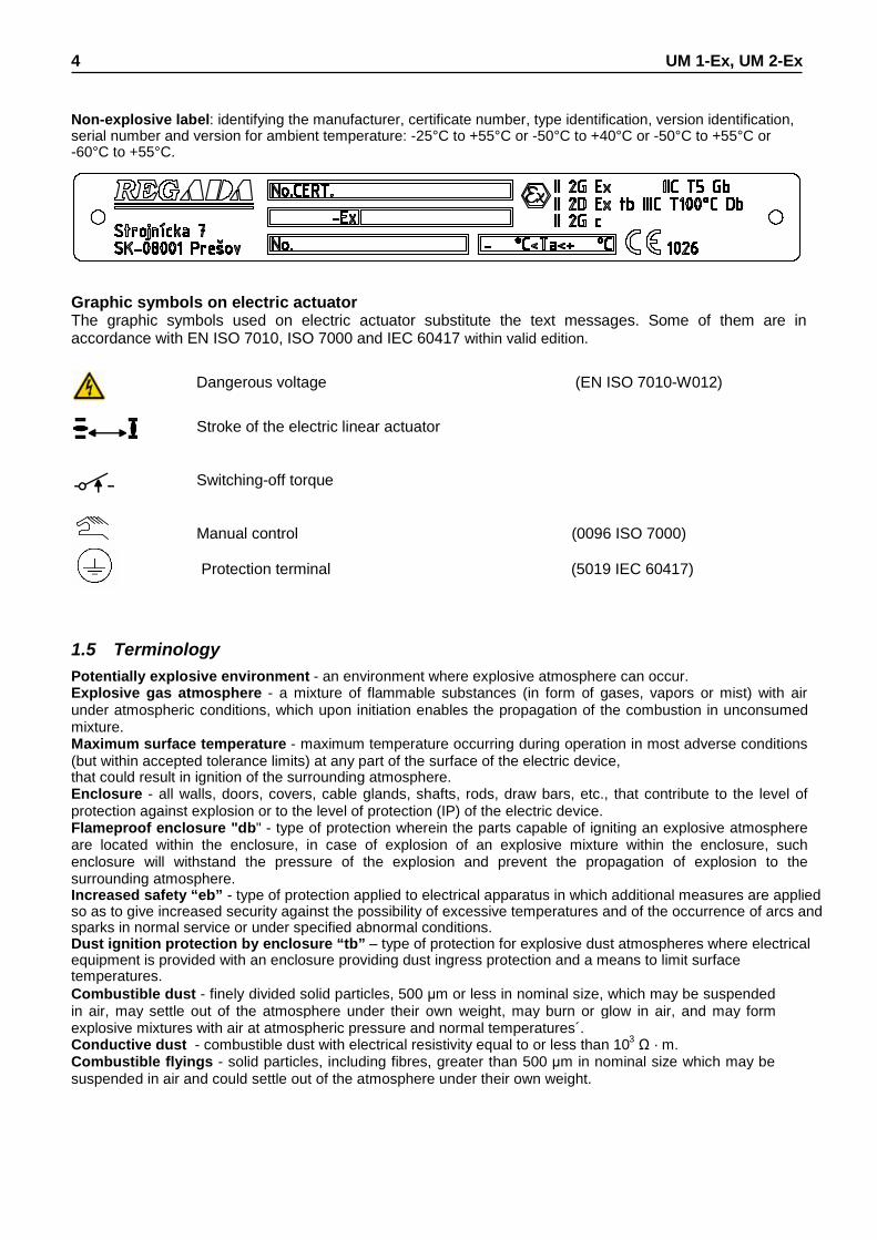
Non-explosive label: identifying the manufacturer, certificate number, type identification, version identification, serial number and version for ambient temperature: -25°C to +55°C or -50°C to +40°C or -50°C to +55°C or -60°C to +55°C.
Graphic symbols on electric actuator The graphic symbols used on electric actuator substitute the text messages. Some of them are in accordance with EN ISO 7010, ISO 7000 and IEC 60417 within valid edition.
Dangerous voltage (EN ISO 7010-W012)
Stroke of the electric linear actuator
Switching-off torque
Manual control (0096 ISO 7000)
Protection terminal (5019 IEC 60417)
1.5 Terminology Potentially explosive environment - an environment where explosive atmosphere can occur. Explosive gas atmosphere - a mixture of flammable substances (in form of gases, vapors or mist) with air under atmospheric conditions, which upon initiation enables the propagation of the combustion in unconsumed mixture. Maximum surface temperature - maximum temperature occurring during operation in most adverse conditions (but within accepted tolerance limits) at any part of the surface of the electric device, that could result in ignition of the surrounding atmosphere. Enclosure - all walls, doors, covers, cable glands, shafts, rods, draw bars, etc., that contribute to the level of protection against explosion or to the level of protection (IP) of the electric device. Flameproof enclosure "db" - type of protection wherein the parts capable of igniting an explosive atmosphere are located within the enclosure, in case of explosion of an explosive mixture within the enclosure, such enclosure will withstand the pressure of the explosion and prevent the propagation of explosion to the surrounding atmosphere. Increased safety “eb” - type of protection applied to electrical apparatus in which additional measures are applied so as to give increased security against the possibility of excessive temperatures and of the occurrence of arcs and sparks in normal service or under specified abnormal conditions. Dust ignition protection by enclosure “tb” – type of protection for explosive dust atmospheres where electrical equipment is provided with an enclosure providing dust ingress protection and a means to limit surface temperatures. Combustible dust - finely divided solid particles, 500 μm or less in nominal size, which may be suspended in air, may settle out of the atmosphere under their own weight, may burn or glow in air, and may form explosive mixtures with air at atmospheric pressure and normal temperatures´. Conductive dust - combustible dust with electrical resistivity equal to or less than 103 Ω · m. Combustible flyings - solid particles, including fibres, greater than 500 μm in nominal size which may be suspended in air and could settle out of the atmosphere under their own weight.

UM 1-Ex, UM 2-Ex 5
!
1.6 Instructions for stuff training Requirements for specialized skills of persons performing assembly, operation and maintenance
Electric connection can be performed only by an acquainted person, i.e. an electrical engineer with professional education of electrical engineering at an apprentice school or a technical school (secondary, complete secondary or university education) and whose qualification was verified by an educational facility authorised to verify professional qualification.
Service can be performed only by workers professionally qualified and trained by the producer or contracted service centre!
1.7 Warning for safety use
1. Products are assigned for operation in environments consist from gases, steams and vapours or with flammable conductive dusts, temperature range from –25°C to +55°C or –50°C to +40°C or -50°C to +55°C or -60°C to +55°C, with pressure range from 0.8 to 1.1 bar. EA can be installed at areas specified as zone 1,2,21,22.
It matters about following products are designated for enviroment: - group II - the category 2 - for type of the atmospheres G or D - subgroup C - temperature class T5.
2. Products are designed according to standards for electrical and non-electrical devices assigned for areas with danger of explosion:
- for electric parts: EN/IEC 60079-0, EN/IEC 60079-1, EN/IEC 60079-7 and EN/IEC 60079-31. - for non-electric parts: EN 1127-1 , EN 13463-1 and EN 13463-5.
3. The maximum surface temperature of the actuator for given group T5 is not allowed to exceed +100°C. 4. If the actuator is placed on device which regulate medium with higher temperature than +55°C, protect
the actuator by additional construction in order to maintain ambient temperature max. +55°C and also to stop temperature transmitting through junction component!
5. Cable glands blinds are assigned only for transport and storage period, i.e. for period till the actuator is builded into operation with danger of explosion, than blinds must be replace by connecting cable.
6. If any of the cable glands are not used to install a cable, it must be replaced with certified Ex plug of the approved type, secured with WEICONLOCK AN 302-43 adhesive.
7. Temperature on entry cables is max. 90°C. 8. ATTENTION: THE COVER CAN BE REMOVED 60 MIN. AFTER POWER SUPPLY IS
SWITCHED OFF! USE SCREWS WITH A TENSILE STRENGTH ≥ 700 N/mm2. 9. WARNING – POTENTIAL ELECTROSTATIC CHARGING HAZARD.
During operation of EA it must be prevented any process with intensive formation of electrostatic charge stronger than manual friction of his surface. Product protection EA UM 1-Ex, UM 2-Ex does not have own short-circuit protection, therefore there must be included suitable protective device into the supply power (circuit breaker, or fuse), which serves at the same time as main switch. Type of equipment from a connection point of view: The equipment is designed for permanent connection.
1.8 Warranty conditions The supplier is responsible for completeness of the delivery and guarantees these specifications of the product which are stated in the Contract. The supplier is not responsible for any deterioration of parameters caused by the customer during storage, unauthorised installation or improper operation.
!
!

6 UM 1-Ex, UM 2-Ex
1.9 Under-guarantee and after-guarantee service Our customers are provided with professional service of our firm in installation, operation, service, maintenance, revision and help in troubleshooting for all our products. Under-guarantee service is performed by the service department of the production plant, or by a contracted service centre according to a written claim.
In case of occurring of any fault please let us know it and state: • type code • serial number • ambient parameters (temperature, humidity...) • duty cycle including frequency of switching • type of switching-off (position or torque) • set switching-off torque • type of fault - description of claimed fault • it is recommended to place also Installation certificate.
It is recommended to have after-guarantee service performed by the service department of the production plant, or by a contracted service centre, with national laws.
1.9.1 Lifetime of actuators The lifetime of an electric actuator (EA) is at least 6 years. EA used for closing mode (closing valves) comply with the requirements for at least 15,000 working cycles
(cycle C – O – C at 30 revolutions per operating stroke:for multi-turn EA) EA used for regulating/modulating operation (control valves) comply with the below stated numbers of operating
hours at the total number of 1 million start-ups: Switching frequency
max. 1,200 [h-1] 1,000 [h-1] 500 [h-1] 250 [h-1] 125 [h-1] Minimal lifetime expectancy – number of operating hours
850 1,000 2,000 4,000 8,000 Time of net operation is min. 200 hours, max. 2,000 hours. Lifetime at operating hours depends on loading and switching frequency. Note : High switching frequency does not ensure better regulation. Setting of regulation parameters should be therefore made with the inevitably necessary switching frequency needed for the process in question
1.10 Operation conditions 1.10.1 Product location and operation position EA may be installed and operated in enclosed locations of industrial facilities with no temperature and moisture regulation, protected from direct climatic effects (such as direct sunlight). Moreover, special “marine” versions may be used in waste water treatment applications, water management, selected chemical applications, tropical environments and coastal areas.
Warning: Actuator installed on the open place must be protected against a direct climate effects by shelter. Installation and operation of EA is possible in any position. Vertical position of output part axis and with the control part above the valve is usual.

UM 1-Ex, UM 2-Ex 7
1.10.2 Working enviroment
According to valid standard IEC 60 721-2-1, there are delivered these versions of electric actuators: 1) Version „temperate“ for type climate temperate 2) Version „cold“ - for type climate cold 3) Version „tropical“ for type climate tropical and dry 4) Version „marine“for type climate marine. 5) Version „arctic“ for type climate very cold.
In accordance with IEC 60 364-1, IEC 60 364-5-51 and IEC 60 364-5-55 within valid edition the EA have to resist external effects and operate reliably: In the conditions of the following types of environment: • warm mild to very hot dry with temperatures -25°C to +55°C .....................................................................AA 7* • cold, warm mild to hot dry with temperatures -50°C to +40°C ....................................................................AA 8* • cold, hot dry to slightly hot dry with temperatures -50°C to +55°C.................................................. AA 8*+AA 7* • cold to slightly hot dry with temperatures -60°C to +55°C .............................................................. AA 1*+AA 7* • with relative humidity 10÷100%, including condensation with maximum content 0,028kg of water
in 1kg of dry, with temperatures stated above ...........................................................................................AB 7* • with relative humidity 15÷100%, including condensation with maximum content 0,036kg of water in 1kg of dry
air, with temperatures stated above ..........................................................................................................AB 8* • with relative humidity 10÷100%, including condensation with maximum content 0,036 kg of water
in 1kg of dry air, with temperatures stated above ......................................................................... AB 8*+AB 7* • with relative humidity 10÷100%, including condensation with maximum content 0,036 kg of water
in 1kg of dry air, , with temperatures stated above ....................................................................... AB 1*+AB 7* • with elevation up to 2000 m, with barometric pressure range from 86 kPa up to 108 kPa........................ AC 1* • with exposure to intensive water jets (IPx6) ............................................................................................... AD 6* • with shallow immersion – (protection enclosure IP x 7) ........................................................................... AD 7* • with submersion – (product with enclosure IPx8)....................................................................................... AD 8* • with strong dustiness – with a possibility of influences of inflammable, non-conducted and non-explosive
dust; the middle layer of dust; the dust drop more than 350 but not more than 1000 mg/m2 per day (products with protection enclosure of IP 6x) .............................................................................................................AE 6*
• expose to corroding or pollute chemical substances during producing or using of these substances); at places where is handled with small quantity of chemical products and these can accidentally get in contact with an electric device ............................................................................. AF 3*
• with permanent exposure of big amount of corroding or contaminated chemical and salt fog in execution for sea environment, fog sewage water disposal plant and some chemical plant .........................................AF 4*
• with a possibility of influences of mechanical stress: • medium sinusoid vibrations with frequency in range from 10 up to 150 Hz, with shift amplitude of 0,15
mm for f<fp and acceleration amplitude 19,6 m/s2 for f>fp (transition frequency fp is from 57 up to 62Hz)AH 2* • medium impacts, shocks and vibrations .............................................................................................. AG 2*
• with serious danger of plants and mould growing .......................................................................................AK 2* • with serious danger of animal occurrence (insects, birds, small animals) ..................................................AL 2* • with detrimental influence of radiation:
• of stray current with intensity of magnetic field (direct or alternate, of mains frequency) up to 400A.m-1AM2-2* • of sun radiation with intensity > 500 and < 700W/m2................ .......................................................... AN 2*
• with effects of medium seismic activity with acceleration > 300 Gal < 600 Gal ..........................................AP 3* • with direct endanger by storm .................................................................................................................... AQ 3* • with quick air movement and strong wind ....................................................................................... AR 3 , AS 3* • stand on a conductive bottom) ................................................................................................................... BC 3* • with a danger of inflammable gases and vapours explosion - for Ex of version ....................................BE 3N2* • fire risks ............................................................................................................................................... BE 2* * Marking in accordance with IEC 60364-1, IEC 60 364-5-51 and IEC 60 364-5-55 within valid edition
1.10.3 Power supply and duty cycle Power supply:
electric motor ......................................... 24 V AC/DC; 120 V AC, 230 resp. 220 V AC; 3x400 resp. 3x380 resp. 3x415 V AC resp. 3x460 V AC ±10%, according to valid certificates control................................................................................................. 24 V AC resp. 220-240 V AC ±10% Power supply frequency.......................................................................................50 Hz, or 60**Hz ± 2 %

8 UM 1-Ex, UM 2-Ex
** Rotation speed will increase 1,2 times, and torque will decrease 1,2 times
Duty cycle - according to EN/IEC 60034-1 within valid edition: EA UM 1-Ex, UM 2-Ex are designed for remote control:
• short-time operation S2-10 min • intermitted operation S4-25%, max. 90 cycles per hour
EA with controller are designed for for automatic regulation: • intermitted operation S4-25%, 90 up to 1200 cycles per hour
Note: 1. Duty cycle consist of load type, load factor and switching rate. 2. Once EA is connected to the external controller unit, also use it as a control EA where the
max. load torgue reaches the 0.7 multiple of the maximum loading torgue for remote operated EA UM 1-Ex, UM 2-Ex
1.11 Packing, transport, storing and unpacking Surfaces without surface treatment are treated by conservation preparation MOGUL LV 2-3 before packaging . Conservation is not necessary if the following storage conditions are complied with: • Storage temperature: -10 to +50 °C • Relative air humidity max.80 % • Electric actuators and their accessories must be stored in dry, well ventilated covered spaces, protected against impurities, dust, soil humidity (by placement to racks, or on palettes), chemicals and foreign interventions • There shall be no corrosive gases present in the storage areas. The of UM 1-Ex, UM 2-Ex are delivered in solid packages guaranteeing resistance in accordance with EN/IEC 60 654. Package is a box. Products in boxes is possible to load on the pallets (pallet is returnable). On the outer side of the package is stated:
• manufacturer label, • name and type of product, • number of pieces, • other data – notices and stickers.
The forwarder is obliged to secure packed products, loaded on transportation means, against self-motion; if open transportation means are used, to secure their protection against atmospheric precipitations and splashing water. Displacement and securing of products in transportation means must provide their stable position, exclude the possibility of their inter-collision and their collision with the vehicle walls. Transportation can be executed by heatless and non hermetic spaces of transportation vehicles with influences within the range: - temperature: -25°C up to +50°C (a strange version –50 ° C up to +45 ° C) - humidity: 5 up to 100 %, with max. water content 0.028 kg/kg of dry air - barometric pressure 86 up to 108 kPa After receiving EA check whether during transport or storage the actuator was not damaged. Compare also whether the parameters on their nameplates are in accordance with accompanying documentation or the Contract. If any discrepancy or fault occur inform immediately your supplier. If the actuators and accessories are not immediately installed, they have to be stored in dry, well-ventilated sheltered rooms, protected against dirt, dust, soil humidity (with placing onto shelves or onto pallets), chemical impacts and encroachment, at ambient temperature from -10°C up to +50 °C and relative humidity max. 80 %, in special version at temperature –50°C do +40°C. • It is forbidden to store EA outside or in areas not prevented against direct impact of climate. • Strains of the surface finishing should be promptly removed if any – it can prevent the product against
corrosion damages. • While storing more than one year it is necessary to check lubrication filling before the actuator is put into
operation. • The EA installed but not operated are to be protected the same way as when storing (e.g. with a wrapping). • After it is mounted onto a valve in free and wet areas or in areas where temperature is changing it is
necessary to connect the space heater – to prevent the actuator against corrosion resulted from water condensed in the control part.
• Remove odd conservation grease as late as before putting into operation.

UM 1-Ex, UM 2-Ex 9
1.12 Assessment of the product and packaging and removal of contamination The product and its package are made of recycling materials. Do not throw the single parts of the package and of the product after their life but sort them according to instructions in corresponding executives or regulations of environment protection, and allow their recycling. The product and its packing are not a source of any environment pollution or contamination and do not contain any dangerous waste.
2. Description, function and specifications 2.1 Description and function EA UM 1-Ex, UM 2-Ex are of compact construction. They are composed of two functionally different main parts. The gear part is made up by a flange with a connecting part resp. linear mechanism for connection onto a controlled device, and gears placed in the bottom; on the other side drive mechanisms for control part units are surfaced. The control part (Fig. 1, 1a ) is placed on a control board (1) consisting of: • electric motor (2) (at single-phase version with capacitor) • torque unit (5) (controlled with a worm axial shift) • position-signaling unit (3) with a position transmitter (6)- positioner (resistive - potentiometer, capacitive or
electronic position transmitter) (7) and with a mechanical local position indicator (4) • space heater (8) with thermal switch • electronic module (9) • electrical connection through terminals (10), located in the control area and cable glands Ex d version
Additional accessories: Manual control: made up by a hand wheel with a worm gearing. Electric local control
Fig.1
10
1
3
8
2 4
7
6

10 UM 1-Ex, UM 2-Ex
5
9
Fig.1a

UM 1-Ex, UM 2-Ex 11
2.2 Basic specifications
Basic EA specifications: are given in Table 1. Table 1: Basic EA specifications
Electric motor 1) Nominal
current
Type
num
ber
Operating speed
2)
Num
ber r
evol
.
Max. load torque
Switching-off torque
±10 [%] Wei
ght
Power supply voltage power speed
nom
inal
star
ting
±20
% Capacitor
capacity.
[1/min] [rev] [Nm] [Nm] [kg] [V] [W] [1/min] [A] [μF/V AC] 1 2 3 5 6 7 8 9 10 11 12 13 50Hz 60Hz
10 26 16-32
20 13 8-16
40 6 4-8
80 3 2-4
230 (220) 40 1350
(1250) 0,53 1 5/400
10 12 26 13-32
20 24 13 8-16
40 48 6 4-8
80 96 3 2-4
Sin
gle-
phas
e
120 (110)
50/60Hz 40 1600 0,67 9,0
10 26 13-32
20 13 8-16
40 6 4-8
80 3 2-4 Sin
gle-
phas
e/
Dire
ct c
urre
nt
24 AC/DC 53 2600 3,1 -
10 54 32-64 20 26 16-32 40 13 8-16
UM
1-E
x
type
num
ber 1
36
80 7 4-8
14 -
15
Thre
e-ph
ase
3x400 (3x380)
resp. 3x415
73 1300 0,21 0,4 -
10 68 45-80 15 46 30-60 20 34 24-40
230 (220) 120 2600 1,0 1,9 8/450
10 12 68 45-80 15 18 46 30-60
20 24 34 24-40
Sin
gle-
phas
e
120 50/60Hz 120 3100 2,0 3,8 8/450
10 68 45-80
15 46 30-60 93 3300
20 34 24-40
Sin
gle-
phas
e/
Dire
ct c
urre
nt
24 AC/DC
100 3350 4,9 - -
10 85 60-100
15 68 48-80
20 51 36-60
UM
2-E
x
type
num
ber 1
37
40
1 –
160
25,5 18-30
20 -
24
Thre
e-ph
ase
3x400 (3x380) resp. 3x415
180 2650 0,6 2,4 -
1) Switching elements for different type of load (also for EA) defines standard EN/IEC 60 947-4-1. 2) Anomaly of operating speed ±10% at 230 V resp. 220 V AC, 3x400 resp. 3x380V resp. 3x415 V AC.

12 UM 1-Ex, UM 2-Ex
Additional technical data: EA protection enclosure: ............................................................ IP 66/IP 68 (EN/IEC 60 529 within valid edition) According to definition for EA, enclosure IP68 fulfills following requirements: -water column max. 10m -time of continious submersion in water max. 96 hours Mechanical ruggedness:
sinusoidal vibrations: with frequency in range 10 to 150 Hz, with shift amplitude of 0,15 mm for f < fp, with acceleration amplitude of 19,6 m/s2 for f > fp, (transition frequency fp = 57 to 62 Hz)
drop resistance:...............................................................................................300 drops with acceleration 2 m.s-2 seismic resistance:...........................................................................amplitude of the shock off 6 on Richter scale
Self-locking: ........................................................................................................................... the EA is self-locked Electric motor protection: ....................................................................................................... with thermal switch EA braking: .......................................................................................................................................... by roller bief Output part backlash:........................................................................... max.5 ° at load of 5%-of maximum torque
Electric control: • remote control (the output element of the EA is controlled with supply voltage), resp. by feeding of unified
signal Adjustment of the limit positions: The limit position switches are set to the number of work turns with accuracy of +/-5% of the stroke specified in the EA nameplate. Additional position relays (S5,S6) are adjustment ..........................................cca 1 rev. beneath the limit switches Hysteresis of position switches..........................................................................max. 5% from stroke on nameplate Unless the customer specifies the value of the particular working revol., revol. are set to 5st degree of the selected stroke order – see Table 5..
Adjustment of the torque switches: If other adjustment not specified the switching torque is set to the maximum value with tolerance of ±10 %. Switches (S1,S2,S3,S4,S5,S6) UM1-Ex,UM 2-Ex: Type D 38: sliver contacts – standard version voltage 250 V(AC); 50/60 Hz; 16(4) A; cos ϕ=0,6 resp.: 24 V(DC); T=L/R=3ms; min. current 100mA Type D 41: gold-plated contacts (is not valid for sitches S1, S2 in the version with reverse contactors) voltage 0,1 (0,05) A, max. 250 VAC; 0,1 / 24 VDC; T=L/R=3ms; min. current 5mA Relay thrust of switch S1, resp. S2 (ReS11, ReS12):
Model RT 424 - 250 V AC, 8 A; 24 VDC, 8 A; max. switching-on power AC 2000 VA
Space heater (E1)
Space heater - supply voltage: ................................. corresponding with motor supply voltage (max. 250 V AC) UM 1-Ex:
Heating power: ........................................................................................................................ cca 20 W/55 °C Switching resistor ................................................................................................................ with thermal switch
UM 2-Ex: Heating power: ........................................................................................................................ cca 40 W/55 °C Switching resistor .......................................................................................................................thermal switch
Thermal switch of space heater (F2)
Supply voltage: ................................ corresponding with motor supply voltage (max. 250V AC) Switching-off temperature:................ +20°C ± 3K Switching-on temperature:................ +30°C ± 4K
Manual control: By handwheel after unscrewing the locking screw . Rotate the handwheel clockwisely to move the output shaft in the direction „Z“.

UM 1-Ex, UM 2-Ex 13
Position transmitters Resistive position transmitter Resistance (single B1) .....................................................................................................................100; 2 000 Ω (double B2) .......................................................................................................... 2x100 Ω, 2x2000 Ω Operating life of transmitter ........................................................................................................... 1.106 cycles Load capacity ................................................................................ 0,5 W do 40 °C, (0 W/125°C) Maximum current of sliding contact ....................................................................................................... max.35 mA Maximum supply voltage............................................................................................................. PxR V DC/AC Potentiometer linearity error ...................................................................................................................... ±2,5 [%]1) Potentiometer hysteresis ...............................................................................................................max. 2,5 [%]1) Potentiometer values at limit positions: ............................................... “O“ (open)...... ≥ 93%, ”Z“ (closed).......≤ 5%
Capacitive (B3): non-contact, life 108 cycles 2-wire connection with built-in power supply or without built-in power supply
The current signal 4 ÷ 20 mA (DC) is acquired from the capacitive transmitter supplied from the internal or an external voltage supply source. The electronics of the transmitter is protected against eventual wrong polarity and current overloading. The entire transmitter is galvanic insulated so several transmitters can be connected to one external voltage source.
Power supply voltage (with power supply) ................................................................................................ 24 V DC Power supply voltage (without power supply).................................................................................. 18 to 28 V DC Ripple voltage .........................................................................................................................................max. 5% Max power input ............................................................................................................................................ 0,6 W Load resistance ......................................................................................................................................0 to 500 Ω Load resistance can be single side grounded. Influence of resistance on output current...........................................................................................0,02%/100 Ω Influence of voltage on output current..................................................................................................... 0,02%/1V Temperature dependency .......................................................................................................... 0.5% / 10 °C Output signal values at limit positions:
“O“............. 20 mA (terminals 81; 82) “Z“ ............... 4 mA (terminals 81; 82)
Values tolerance of output signal of EPV “Z“ ............ +0,2 mA “O“ ............ ±0,1 mA
DCPT2 – current transmitter (B3)
- 2-wire connection without built-in power supply or with built-in power supply
Current signal .......................................................................4 ÷ 20 mA (DC) with optional mirroring (20 ÷ 4 mA) Mode of operation...............................................................................................contactless, magnetic resistance Transmitter increments without gears .........................................................................................................0.352 ° Loading resistor: ........................................................................................................................... 0 through 500 Ω Operating stroke .......................................................................... 35 to 100% of the rated stroke at the gear ratio Non-linearity...........................................................................................................................................max. ±1 % Non-linearity - geared .........................................................................................................................max. ±2.5 % Power supply voltage for version without power source ....................................15 through 28 V DC, max.42 mA Power supply voltage for version with built-in power source.....................................................................24 V DC Operating temperature........................................................................................................................-25 to +70°C Linearity deviation:.....................................................................................................................................±2.5 %1) Hysteresis ...........................................................................................................................................max. 2.5 %1) Error messages .............................................................................................................................by flashing LED
1) from rated value of transmitter referred to output values

14 UM 1-Ex, UM 2-Ex
Electronic positional transmitter (EPV) - converter R/I (B3) 2-wire version, resp. 3-wire (without built-in power supply, or with built-in power supply)
Output signal for 2-wire version .......................... 4 ÷ 20 mA (DC) Output signal for 3-wire version .......................... 0 ÷ 5 mA (DC) ............................................................................ 0 ÷ 20 mA (DC) ............................................................................ 4 ÷ 20 mA (DC) Power supply voltage for 2-wire version without built-in power supply................................... 15 to 30 V DC Power supply voltage for 2-wire version -with built-in power supply ..................................... 24 V DC ± 1,5% Load resistance for 2-wire version ............................................................................ max. RL=(Un-9V)/0,02A [Ω] (Un – voltage [V]) Power supply voltage for 3-wire version ..................................................................................................±1,5 % Load resistance for 3-wire version ........................................................................................................max. 3 kΩ Temperature dependency...................................................................................................max. 0,020 mA / 10 °C Output signal values at limit positions on the terminal 81,82 ....................................... „O“.... 20 mA (5 mA, 10 V) ..................................................................................................................................... „Z“..... 0 mA (4 mA, 0 V) Values tolerance of output signal ....................................................................................................... „Z“ +1,5 %1) .... ...............................................................................................................................................„O“±1,5 %1) Linearity deviation......................................................................................................................................±2,5 %1)
Hysteresis ...........................................................................................................................................max. 2,5 %1)
1) from rated value of transmitter referred to output values
Lubricators : - see chapter Maintenance - extent and periodicity
2.2.1 Mechanical connection − flange (ISO 5210), pillars
Basic and connecting dimensions are given in dimensional drawings.
2.2.2 Electrical connection Terminals (X) for EA UM 1-Ex, UM 2-Ex - max. 32 screw-less terminals
with connecting wire cross-section of 0.08 to 1.5 mm2 For non-armored cables - as standard (temperature on entry of cables is max. 90°C):
UM 1-Ex, UM 2-Ex: 1 cable gland - 1xM16x1,5 (øD = 3,2 to 8,7 mm); 1 cable gland - 1xM16x1,5 (øD = 6,1 to 11,7 mm); 1 cable gland - 1xM16x1,5 (øD = 6,5 to 14,0 mm); For armored cables - upon special order: UM 1-Ex, UM 2-Ex: 1 cable gland - M20x1,5 (øD = 3,1 to 8,6 / øD1= 6,1 to 13,4 mm); 1 cable gland - M20x1,5 (øD = 6,1 to 11,6 / øD1= 9,5 to 15,9 mm); 1 cable gland - M20x1,5 (øD = 6,5 to 13,9 / øD1= 12,5 to 20,9 mm); øD = connecting cable diameter øD1= outside diameter of the connecting cable with armoring Wire stripping lenght of the wires for screwless terminals is from 8 to 9mm.

UM 1-Ex, UM 2-Ex 15
Table 2: Association of the cable diameter with cable glands type
A2F 16 / - M16x1,5 - 3,2 - 8,7
A2F 20S16 / A2F 20s/16 - 3,2 - 8,7
A2F 20S - 6,1 - 11,7
A2F 20 - 6,5 - 14,0
T3CDS 16 / - M16x1,5 3,1 - 8,6 6,1 - 13,1
T3CDS 20S16 / T3CDS 20s/16 3,1 - 8,6 6,1 - 13,1
T3CDS 20S / - 6,1 - 11,6 9,5 - 15,9
T3CDS 20 6,5 - 13,9 12,5 - 20,9
PXSS2K*** 20S16 / PXSS2K*** 20s/16 - 3,1 - 8,6
PXSS2K*** 20S / - - 6,1 - 11,7
PXSS2K*** 20 - 6,5 - 14,0
PX2K*** 20S16 / PX2K*** 20s/16 max. 11,7 6,1 - 13,1
PX2K*** 20S / - max. 11,7 9,5 - 15,9
PX2K*** 20 max. 12,9 12,5 - 20,9
E1F* 20S16 / E1F* 20s/16 3,1 - 8,6 6,1 - 13,1
E1F* 20S / - 6,1 - 11,6 9,5 - 15,9
E1F* 20 6,5 - 13,9 12,5 - 20,9
E2FW 20S16 / - 3,1 - 7,8 6,1 - 13,1
E2FW 20S / - 6,1 - 11,0 9,5 - 15,9
E2FW 20 / - 6,5 - 13,4 12,5 - 20,9
Lex 216******* HTS M16x1,5 - 7,0 - 11,0
Lex 220******* HTS M20x1,5 - 8,0 - 14,0
K32.AC 12.20..13CR.exd... / CR*** 16 3,4 – 8,4 8,4-13,5
K32.AC 12.20..16CR.exd... / CR*** 20S 7,2-11,7 11,5-16,0
K32.AC 12.20..21CR.exd... / CR*** 20 9,4-14,0 15,5-21,1
K35.AC 15.20..13CRCexd... / CR-C*** 16 max. 11,7 9,0/8,4 - 13,5
K35.AC 15.20..16CRCexd... / CR-C*** 20S max. 11,7 11,5-16,0
K35.AC 15.20..21CRCexd... / CR-C*** 20 max. 14,0 15,5-21,1
A*LDS*F 16 M16x1,5 - 4,0 - 8,4
A*LDS*F 20s - 7,2 - 11,7
A*LDS*F 20 - 9,4 - 14,0
CR-U 16 - 3,4 – 8,4
CR-U 20S - 4,8-11,7
CR-U 20 - 9,5-14,0
501/421 (2K/Os/O) M16x1,5 - 3,2-8,0 / 3,2-8,0 / 6,5-10,9
501/421 (Os/O/A) M20x1,5 - 3,2-8,0 / 6,5-11,9 / 10,0-14,3
501/423 (Os/O) M16x1,5 - 3,2-8,0 / 6,5-10,9
501/423 (Os/O/A) M20x1,5 - 3,2-8,0 / 6,5-11,9 / 10,0-14,3
501/453/RAC (Os/O) M16x1,5 3,2-8,0 / 6,5-10,9 5,5-12,0 / 9,5-16,0
501/453/RAC (Os/O/A) M20x1,5 3,2-8,0 / 6,5-11,9 / 10,0-14,3 5,5-12,0 / 9,5-16,0 / 12,5-20,5
501/453/UNI (Os/O) M16x1,5 3,5-8,1 / 6,5-10,9 5,5-12,0 / 9,5-16,0
501/453/UNI (Os/O/A) M20x1,5 3,5-8,1 / 6,5-11,4 / 8,4-14,3 5,5-12,0 / 9,5-16,0 / 12,5-20,5
ICG 653/UNIV (Os/O/A) M20x1,5 x a) max. 8,0 / 8,8 / 10,8 5,5-12,0 / 9,5-16,0 / 12,5-20,5
HSK-M-Ex d M16x1,5 - 5-10 / 3-7
HSK-M-Ex d M20x1,5 - 10-14 / 7-12
HSK-Mz-Ex d M16x1,5 - 5-10
HSK-Mz-Ex d M20x1,5 - 10-14
EX1126.17.**.**0 M16x1,5 - 3-5 / 7-10
EX1126.20.**.**0 M20x1,5 - 5-9 / 11-14
c)
x
x
M20x1,5 x
b)
a)M20x1,5
M20x1,5 x a)
M20x1,5 c)
c)
x c)
x b)
b)x
a)
outside inside
x c)
Encapsulation
of cable 1)
armored cables
and shielded
Diameter of cable
non-armored cables and not shielded
x
Pepp
ers
x
Version Thread
Type cable
M20x1,5
M20x1,5
CM
P / S
tahl
Pflit
sch
x
Pflit
sch
/ Pep
pers
Haw
ke
x c)
x c)
x a)
c)
c)
M20x1,5
M20x1,5
M20x1,5
M20x1,5
x
x b)
Hum
mel
Agr
o
x
1) Encapsulation of cable: For cable glands fixing there is used glue WEICONLOCK AN 302-43. a) Barier gland – type of gland with Compound (Barrier) Seal b) Sealing of cable core using the filling compound, see section 3.1.2 Cable routing for their connection. c) The cable used must be in accordance with STN EN 60079-14, chapter 10.6.2. Attention: Thermic resistance incoming wires must be minimum +90°C.

16 UM 1-Ex, UM 2-Ex
Table 3: Wire cross-section conversion table (mm2 – AWG)
Wire cross-section conversion table (mm2 – AWG) Wire cross-section mm2 AWG 0,05 30 0,2 24 0,34 22 0,5 20 0,75 18 1,5 16 2,5 14 Tightening torque conversion table (N.m – lbs.-in) Tightening torque N.m lbs.-in 0,2 2,7 0,3 4 0,5 7 Protective terminal: Upon start-up in operation - at equipment installation: - for safe use of the actuator it is necessary to connect the outside and inside grounding terminal. The position of the outside and inside grounding terminal can be seen in Fig. 1c and Fig. 1d. HP3 insulated eyelet crimping pliers should be used to crimp wire to the outside grounding terminal (fy CEMBRE). - a power switch/circuit-breaker must be installed on the power supply cable, as close as possible to the device, easily accessible to the operator and identified as the actuator disconnecting device. Outside and inside, mutually interconnected and identified with a protective grounding symbol.

UM 1-Ex, UM 2-Ex 17
Product protection We recommend to use fuses for protection of product. Table 4: Fuse values and characteristics
Type
Order code Voltage
Freq
uenc
y (H
z) Electric
motor Power /
Power input (W)
max. curent EA (A)
Fuse values F3
136.X-0XXXX/YY 230 VAC 136.X-LXXXX/YY 220 VAC 50 40/90 0,8 T 1,6 A / 250 V
136.X-1XXXX/YY 3x400 VAC 3x415 VAC U
M 1
-Ex
136
136.X-MXXXX/YY 3x380 VAC 50 73/110 0,42 T 0,8 A / 250 V
137.X-0XXXX/YY 230 VAC 137.X-LXXXX/YY 220 VAC 50 120/228 1,3 T 1,6 A / 250 V
137.X-1XXXX/YY 137.X-2XXXX/YY
3x400 VAC 3x415 VAC
137.X-MXXXX/YY UM
2-E
x 13
7
137.X-NXXXX/YY 3x380 VAC 50 180/300 0,82 T 1,6 A / 250 V
Electric connection: - according to the wiring diagram stuck into the case of the EA.
OUTSIDE GROUNDING TERMINAL
Fig.1c
INSIDE GROUNDING TERMINAL
Fig.1d

18 UM 1-Ex, UM 2-Ex
3. Installation and dismantling of actuator
Abide by safety measures!
Note: Check again if placement of EA reply to chapter "Operation conditions". In case that operation conditions are different from recommended, consultation with producer is needed.
Before starting of mounting the EA onto the valve: • Check again whether the EA was not damaged during storing. • Check whether the adjusted operation stroke and connecting dimensions of the actuator (see the nameplate)
are in compliance with the valve parameters. • In case of inconsonance, perform adjusting according to the part "Adjustment“.
3.1 Installation EA is by the producer adjusted to parameters according to the nameplate. Before installation put the hand wheel on.
3.1.1 Mechanical flange connection • Defat the abutting areas of the connecting flange of the EA valve or the gear carefully; • Lubricate the output shaft of the valve/gear with a grease not containing any acids; • Set the EA to the limit position “closed”, set the valve to the same position; • Put the EA onto the valve with the output shaft reliably stalled in the valve coupling/gear; Attention! Do not adjust EA on an armature forcibly because of damage of the gear! • Use the hand wheel to turn the EA to fit the openings in the EA and valve flanges if needed; • Check whether the connecting flange abuts with the valve/gear; • Fix the flange with four screws (with mechanical strength min 8G) fixed the way the actuator can Be moved.
Tighten the screws equally in cross; • At the end check the correctness of the fixture with the valve with rotating the hand wheel.
3.1.2 Cable routing and connection Direct entry to flameproof enclosure (compound filling around cable cores): Cable glands system must comply with the requirements of EN 60 079 art.10.4.2 direct entry to class flameproof enclosure IIC. Cable glands threads are secured against loosening by WEICONLOCK AN 302-43 adhesive. Therefore during installation of the actuator the customer is required to apply non-explosive sealing device using a compound filling material and sealing tubes. If any of the cable glands are not used to install a cable, it must be replaced with certified Ex plug of the approved type, secured with Loctite 243 adhesive. Temperature on entry cables is max. 90°C. Follow the following instructions when compound filling the cable glands: 1) Remove sufficient length of cable sheathing - minimum length of compound filling must be at least 20mm. 2) Apply silicone putty on individual cable core branching and to the cut edge of the sheating to prevent overflowing of the filling compound during subsequent filling. Apply sealing tubes over cable cores and press the beveled inside edge to the cable sheating. 3) Fill the tube with the cable core using the filling compound prepared according to the instructions. 4) After the compound has cured (about 24 hour) clean the cable under the tube. Remove the tightening nut, compression ring and sealing o-ring from the actuator cable glands and slip these parts over the cable. Route the cable through the body of the cable glands into the actuator and tighten the nut. 5) Connect individual wire cores to the terminals. Advantage: in case of replacement or repair of the actuator, there is no need to cut the cable, it is just released from the cable glands.

UM 1-Ex, UM 2-Ex 19
Sealing of cable core using the filling compound: Cable conductors Filling compound (as an example MC 35/K2 I - Camattini) Tube for competent cable glands Cable Fig. 1e 3.1.3 Electric connection and checking of function Follow up with connecting the EA with mains or master system.
1. Follow instructions in the part "Requirements for professional qualification"! 2. While laying electrical line abide by the instructions for heavy current installations. Power supply cables must be of the type approved. Minimum thermal resistance of power supply cables and wires must be +90°C. 3. Cables to terminal boards or connectors lead through screw cable glands. 4. Before initiation ES into operation internal and external protection terminals are needed to be
connected. 5. Feeding cables are to be fixed to the solid construction at most 150 mm from the cable glands. 6. Torque switching is not fitted with mechanical interlocking device.
Connection with the terminal board: Before the connection remove the actuator case and check whether the type of current, power supply and frequency correspond with the data on the actuator nameplate. Electric connection: • The electric connection should be realized according to the wiring diagram stuck into the case of the EA; • The electric connection should be performed through two cable glands see No. 2.2.2. • Once electrical services are completed put on the cover and fasten it evenly crosswise by bolts. Fasten the
cable glands to ensure specified shielding.
Notes: 1. To connect the input control signals and output signals is needed to use shielded wires with steel wire braid
(Galvanised Steel Wire Braid GSWB Ξ), for example cable type "Bruflex ® HSLCH", 4x0, 5 (company Bruns Kabel).
2. The EA are delivered with cable glands which in case of correct tighten are onto the supply lead allow the protection enclosure of IP 68.
3. The cable is to be fixed the way corresponding with its allowable bending radius not to damage or deform the sealing element of the cable lead. The supply leads have to be fixed onto a fixed construction max. 150 mm from the leads.
4. It is recommended to connect the remote transmitters with shielded wires. 5. The face areas of the control part cover should be clean before fixing it back. 6. The EA is reversible if the time interval between the power supply is switched off and on for the reverse
direction of the output part motion is at least 50 ms. 7. The allowed delay after it is switched off, i.e. time from the switches reaction up to the motor without any
voltage is 20 ms maximally. Observe the valve manufacturer´s instructions with respect to the requirement to ensure switching-off in limit positions through position or torque switches!
!

20 UM 1-Ex, UM 2-Ex
Caution:
1. Power supply to the actuator and connections with switching, protective and safety devices may be carried out only by personnel with appropriate qualification, in compliance with the corresponding standards and wiring diagrams, such as those specified in the Instruction Manual....
2. All terminal connections must be checked after connection of the power supply cables. The conductors must not apply any bending or tensile stress upon the connecting terminals. The following measures should be taken when using aluminum conductors:
3. Immediately before connecting the aluminum conductor, it is necessary to remove the oxide layer on the surface and prevent the oxidation by application of neutral vaseline to protect the connection.
After connection, check the correct direction of the actuator shaft rotation by short activation of the
actuator in intermediate position. This can also be checked by using a stick made of insulating material to activate the corresponding micro-switch - limit, position or torque (depending on the type of actuator control) during operation of the actuator.
If the actuator does not stop, but stops upon signal from micro-switch corresponding to the opposite rotation direction, you will need to change the direction of rotation of the actuator output shaft. In case of an actuator driven by single-phase electric motor, the direction of rotation can be changed by switching the supply cables on the terminals of the electric motor. In case of actuators with three-phase electric-motor, interconnect one of the pairs of conductors on terminals U, V, W of the actuator terminal board. Repeat the function test again. Important! 1) During adjustment, repair and maintenance, secure the actuator by prescribed means in order to prevent its power-up resulting in the possibility of electric shock injury or injury by rotating parts. 2) When reversing the operation of actuators with single-phase electric motor, power supply must never be connected simultaneously to both outputs of the start-up capacitor at the same time, otherwise the capacitor could discharge through torque switch contacts resulting in their sticking together.
After adjustment of the actuator, check its operation using the control circuit. Especially make sure that the actuator starts-up correctly and that the electric motor is disconnected from power supply after triggering of the corresponding micro switch. Otherwise immediately disconnect the power supply to the actuator to prevent damage to the electric motor and try to locate the malfunction. After the EA is electrically connected it is advised to check functions: • After the EA is electrically connected to check the correct functions of the position and the torque switches
S1 - S6 and if needed adapt the order of the single phase leads for the 3-phase electric motor. • Set the valve manually into an mid-position. • Connect the power supply to the terminal for supplying the EA in the direction “opening” and follow the
direction of the output shaft of the actuator rotation. When EA is connected correctly, the output shaft of EA, into the actuator control part from the top, must rotate counterclockwisely. If not, it is necessary to change the phase leads L1 and L3 on the terminals 2 and 4 mutually, valid for 3-phase electric motor. After the exchange is made check the direction of the EA rotation.
• If any of the functions is not correct, check the switches whether they are wired properly according to the wiring diagrams.
3.2 Dismantling
Attention! Before disassembly is necessary to disconnect electric supply of electric actuator! Secure by prescribed way protection against connection of EA to the network and thus potential electrical accident!
• Disconnect the EA from mains. • Disconnect the leads from the EA terminal boards and loosen the cables from cable glands. Pull out the
connectors in case of the connector version. • Loosen the fixing screws of the EA flange and coupling screws and disconnect the EA from the valve. • While sending the EA to be repaired put it into a package solid enough to avoid damages of the EA during
transportation.
!

UM 1-Ex, UM 2-Ex 21
4. Adjustment Keep safety regulations! Follow the prescribed procedure to assure that the EA is not connected to mains when live not to cause any injury by electrical current!
The adjustment is performed with the EA mechanically and electrically connected and the connection and functions were checked. The chapter describes the adjustment of the EA to the parameters given in the nameplate in case that any of its parts is out of tune. The adjusting parts on Fig.1.
Definition of the direction of movement: • movement direction "close" - the output shaft of the actuator rotates in the clockwise direction when looking
into the actuator control part from the top.
4.1 Adjustment of the torque unit The switching - off torque are adjusted by the producer for both directions, i.e. for the direction “opening”
(the torque switch S1) as well as for the direction “closing” (the torque switch S2) to the specified value with tolerance of ±10%. If not stated else they are adjusted to the maximum rate. Adjustment and setting of the torque unit for EA UM 1-Ex actuator to alternative torque values is possible through the use of adjustment screws according to Fig. 2. Switching-off torque can be reduced by rotating the graduated screws along the gauge mark on the arm of the torque unit. Adjustment to longest mark results in resetting the switching-off torque to maximum value. Adjustment to the shortest mark results in the reduction of the switching-off torque.
Adjustment and setting of the torque unit for EA UM 2-Ex actuator to alternative torque values is possible through the use of adjustment segments according to Fig. 2a. Torque can be reduced by releasing the screw and sliding the graduated segment along the gauge mark on the arm of the torque unit. Adjustment towards M results in resetting the switching-off torque to maximum value. Adjustment towards 0 results in reduction of the switching-off torque.
Fig.2
REGULATING SCREW OF TORQUE SWITCH S2
REGULATING SCREW OF TORQUE SWITCH S1

22 UM 1-Ex, UM 2-Ex
4.2 Adjustment of position-signalling unit (Fig.3) UM 1-Ex, UM 2-Ex (Fig.3): By default the actuator is set by the manufacturer to standard stroke (according to specification), as specified in the nameplate. Unless the customer specifies the value of the particular working revotut., revolut. are to 5st degree of the selected stroke order. While setting, adjusting and resetting follow these steps (Fig. 3): • in the version with a resistant transmitter (Fig.4) disengage the transmitter; • set the adjustment wheel to the required degree of the range according to table 5 and Fig.3a by loosening
of the adjustment wheel screw and re-tightening after alignment. When adjusting the adjustment wheel, make sure there is correct alignment with the second level disc.
• loosen the nut (22) with simultaneous holding the central milled nut (23) and then loosen the nut (23) fixing the cams still having the belleville springs which create axial thrust;
• reset the EA to the “Open” position and rotate the cam (29) clockwise (when viewing the actuating plate from above) until switch S3 switches over (25);
• reset the EA by the angle where the “Open” position is to be indicated and turn the cam (31) clock-wise until switch S5 switches over (27);
• reset the EA to the “Closed” position and turn the cam (28) counter clockwise until switch S4 switches over (24);
• reset the EA back by the angle where the “Closed” position is to be indicated and turn the cam (30) counter clockwise until switch S6 switches over (26);
• once the EA is adjusted manually tighten the central milled nut (23) to lock the cams and tighten the lock nut (22) while simultaneous holding the milled nut;
• swing the position indicator discs (31) for the given operating stroke against the gauge mark on the top cover sight;
• once of the position- signalling unit is adjusted also adjust the position transmitter, converter or controller. There is an option of bi-directional signalling at all operating stroke time, i.e. 100 %.
ADJUSTING SEGMENT OF TORQUE SWITCH FOR DIRECTION „CLOSE“
ADJUSTING SEGMENT OF TORQUE SWITCH FOR DIRECTION „OPEN“
TORQUE SWITCH FOR DIRECTION „OPEN“
TORQUE SWITCH FOR DIRECTION „CLOSE“
Fig. 2a

UM 1-Ex, UM 2-Ex 23
Fig.3
26
27
24
25
23
22
30 31
28
29
32

24 UM 1-Ex, UM 2-Ex
1.°
3.° 2.°
4.°
6.°
8.°
Fig.3a
5.°7.°
SLIDING GEAR SCREW
SLIDING GEAR
TABLE 5 STROKE LINE STROKE ANGLE MAX. OPERATING REV.
1.° - 2.° 1,563 3.° 3,125 4.° 6,25 5.° 12,5 6.° 25 7.° 50
I.
8.° 100 1.° 1 2.° 2 3.° 4 4.° 8 5.° 16 6.° 32 7.° 64
II.
8.° 128 1.° 1,25 2.° 2,5 3.° 5 4.° 10 5.° 20 6.° 40 7.° 80
III.
8.° 160

UM 1-Ex, UM 2-Ex 25
4.3 Adjustment of resistant transmitter (Fig.4) The resistant transmitter is in the EA UM 1-Ex, UM 2-Ex used to function as a remote position indicator. Before the resistant transmitter adjustment the position switches have to be adjusted (S3,S4). Adjustment consists in setting of the resistance in the defined limit position of the EA.
Notes: In case that the EA is unused within the complete operating speed range following the angle selected on the particular stroke line, the “Open” limit position resistance value will un-dergo proportional reduction. The transmitters are used with resistance according to the customer's specification. With EA of 2- wire converter a transmitter of 100 Ω resistance is used . To adjust the transmitter follow these steps:
Loosen the fixing screws (9) of the transmitter holder and push the transmitter out of mesh. Put the actuator to the position ”closed” (with the handwheel, until the corresponding position switch S2 or S4
switches). Connect a meter for resistance measuring to the terminals 71 and 73. Rotate the transmitter shaft (11) until
resistance of ≤5% of the nominal transmitter resistance can be read on the meter. In the position put the transmitter to mesh with the drive wheel and fix the fixing screws on the transmitter
holder. Please check the resistance value in both of the final positions and in case of need repeat the procedure.
Once the device is adjusted in a correct way disconnect the meter from the terminal.
4.4 Adjustment of the Electronic Position Transmitter (EPV) - the Resistive Transmitter (Potentiometer) with the Converter PTK 1
4.4.1 EPV – the 2-wire version (Fig. 5,5a) The position transmitter with the converter PTK1 is in the plant adjusted to have the output current signal on the terminals 81-82 as follows: • in the position ”open“ ........................................ 20 mA • in the position ”closed“ ..................................... 4 mA
If the transmitter requires a new adjustment follow these steps:
Adjustment of the EPV – 2 wire version • Put the actuator to the position ”closed“ and switch the
power supply off. • Adjust the resistive transmitter according to the previous
chapter. The resistance is to be metered on the terminals X-Y, resp. R-R (Fig. 5,5a). The used transmitter resistance is 100 Ω.
• Switch the converter′s power supply on. • Turn the adjusting trimmer ZERO, resp. A to adjust the
output current signal rate measured on the terminals 81-82 to 4 mA.
• Set the actuator to the position ”open“. • Turn the adjusting trimmer GAIN, resp. B to adjust the output current signal rate measured on the terminals
81-82 to 20mA. • Check the output signal of the converter in the both limit positions, and repeat the procedure if needed.
11
Fig.4
9
5
Fig.5

26 UM 1-Ex, UM 2-Ex
Note: The output signal of 4-20mA can be adjusted at the range from 75 up to 100% of the rated stroke stated on the actuator′s nameplate. At values less than 75% the value 20mA is reduced proportionally.
4.4.2 EPV – 3-wire version (Fig. 6, 6a) The resistive transmitter with the converter is in the plant adjusted to have the output current signal metered on the terminals 81-82 as follows: • in the position ”open”….…20 mA resp. 5 mA resp. 10 V • in the position ”closed”……0 mA resp. 4 mA resp. 0 V
according to the specified version of the converter.
If the transmitter requires a new adjustment follow these steps: • Put the actuator to the position ”closed” and switch the
power supply off. • Adjust the resistive transmitter according to the previous
chapter. The resistance is to be metered on the terminals X-Y, resp. 0%-100% (Fig. 6, 6a). The used transmitter resistance is 2000 Ω or 100 Ω..
• Switch the converter′s power supply on. • Turn the adjusting trimmer ZERO, resp. A to adjust the output current
signal rate measured on the terminals 81-82 to 0mA resp.4 mA, resp. 0 V.
• Set the actuator to the position ”open“. • Turn the adjusting trimmer GAIN, resp. B to adjust the output current
signal rate measured on the terminals 81-82 to 20mA, resp. 5 mA, resp. 10V.
• Check the output signal of the converter in the both limit positions, and repeat the procedure if needed.
Note: The output signal of (0-20mA, 4-20mA or 0-5mA - according to the specification) can be adjusted at the range from 85 up to 100% of the rated stroke stated on the actuator′s nameplate. At values less than 85% the value of the output signal is reduced proportionally.
Fig. 6
Fig. 5a
Fig .6a

UM 1-Ex, UM 2-Ex 27
4.5 Adjustment of Capacitive Transmitter CPT1/A (Fig.7) The chapter describes adjustment of the capacitive transmitter to the specified parameters (standard values of output signals) in case they are reset. The capacitive transmitter serves as a position transmitter of electric actuators with unified output signal of 4÷20 mA. Note: In case that reversed output signals are needed (in the position ”OPEN” minimum output signal) contact personnel of service centres.
The capacitive transmitter CPT1/A is adjusted by the producer to the fixed operation angle according to the order and wired according to the wiring diagrams placed into the cover. Check the power supply of the user after connecting to terminal of the terminal board before the transmitter is electrically checked. Adjustment of the capacitive transmitter can be performed when the position switches are adjusted. The adjustment is performed with the power supply of 230 V/50 Hz and ambient temperature of 20± 5°C.
The following versions of electric actuators with built capacitive transmitters can be specified: A) The version without any power supply (2-wire version) B) The version with a power supply (2-wire version)
A.) Adjustment of the Capacitive Transmitter without any Power Supply Before connecting check the power supply. The measured voltage should be in range from 18 up to 28 V DC.
The voltage of the power supply must not be in any case higher than 30 V DC. The transmitter can be irreversibly damaged!
While checking or adjusting the output signal of 4÷20 mA follow these steps: • Connect a mA meter of precision class 0,5 and loading resistance lower than 500 Ω serially with the
transmitter (pole “-“; terminal 82) • Put the actuator to the position ”CLOSED”,
the signal value should decrease. • Check the signal value for the position
”CLOSED” (4 mA). • Tune the signal with loosening the fixing
screws (15) and turning the trimmer (10) until the required value of 4 mA is reached. Tighten the fixing screws.
• Put the actuator to the position ”OPEN”, the signal value should raise.
• Check the signal value for the position ”OPEN” (20 mA).
• Tune the signal with turning the trimmer (20) until the required value of 20 mA is reached.
• Check the signal value for the position ”CLOSED” and then for the position ”OPEN”. • Repeat the procedure until the change from 4 to 20 mA is reached with deviation less then 0,5 %. • Disconnect the meter and lock the screws with a varnish.
B.) Adjustment of the Capacitive Transmitter with the Power Supply 1.) Check the power supply: 230 V AC, resp. 24 V AC (according to version) ±10%, on the terminals 1, resp. 60 and 61 2.) While checking or adjusting the output signal of 4÷20 mA follow these steps: • Connect a mA meter of precision class 0,5 and loading resistance lower than 500 Ω on the terminals 81, 82. • Follow the procedure described in the previous chapter A.
The user has to arrange grounding of the 2-wire circuit of the capacitive transmitter to the electrical ground of a joined controller, computer, etc. The grounding should be performed only in one place in any part of the circuit outside the electric actuator!
!
!
Fig.7
15
20
10

28 UM 1-Ex, UM 2-Ex
Note: The trimmer (20) can be used to adjust the output signal of the capacitive transmitter to any value of operation stroke in range from ca 40% up to 100% of the value of the operation stroke adjusted by the producer and stated on the actuator′s nameplate.
4.6 Adjustment of the DCPT2 transmitter Before the transmitter DCPT2 (Fig.8) adjustment the position switches S3 and S4 have to be adjusted. Adjustment consists in setting of the output signal value in the limit positions of the actuator.
By default (unless determined otherwise by the customer), the manufacturer aligns the DCPT2 transmitter so that output signal value 4mA is set for the limit position "closed" and 20 mA for the position "opened". By default the characteristics of the output signal is set to 20-4 mA (descending). Notes 1: -this type of transmitter enables the assignment 4 mA / 20 mA of the output signal value to any limit
position of the actuator. 2:-the transmitter is adjustable within the range of 35 to 100% of the full stroke specified in the nameplate.
4.6.1 Setting of limit positions If limit positions require re-adjustment, proceed as follows:
Adjustment of the "4 mA" position: • Turn on the power supply voltage to DCPT2 • Reset the actuator to the limit position that you want to assign 4 mA signal value to and press (for about 2
seconds) the pushbutton "4", until LED flashes
Adjustment of the "20 mA" position: • Turn on the power supply voltage to DCPT2 • Reset the actuator to the limit position that you want to assign 20 mA signal value to and press (for about
2 seconds) the pushbutton "20", until LED flashes Notes 1: Transmitter error code may result when the first limit position is saved (2x LED flash). The error code is erased by saving of the second limit position, provided that the saved limit positions are within 35 to 100% of the rated stroke specified in the nameplate. If necessary, please change the characteristic of the output signal from descending to ascending or vice versa, according to the following chapter.
4.6.2 Setting of the ascending/descending characteristic of the output signal When the characteristic of the transmitter output signal is changed, the set limit positions "4 mA" and "20
mA" are maintained, however the operating range (stroke of DCPT2) between these two positions is changed to the complement of the original operating range.
When the DCPT2 transmitter is set so that output signal value 4mA is set for the limit position "closed" and 20 mA for the position "opened", the characteristic must be set to 20-4 mA (descending).
When the DCPT2 transmitter is set so that output signal value 20 mA is set for the limit position "closed" and 4 mA for the position "opened", the characteristic must be set to 4-20 mA (ascending).
If you need to toggle the characteristic of the transmitter output signal 4-20 mA (ascending), or 20-4 mA
(descending), please proceed as follows: • Turn on the power supply voltage to DCPT2 • For 4-20 mA (ascending characteristic) press the pushbutton "20" and subsequently "4" and hold both
buttons pressed until LED flashes. • For 20-4 mA (descending characteristic) press the pushbutton "4" and subsequently "20" and hold both
buttons pressed until LED flashes.

UM 1-Ex, UM 2-Ex 29
4.6.3 Calibration MENU The calibration menu enables setting of default parameters and calibration of current values 4 and 20 mA (fine tuning of the value of the output current signals 4 and 20 mA in the limit positions).
Adjustment of default parameters: • Turn off the power supply to the transmitter power supply source. • Press and hold the "4" and "20" adjustment pushbuttons. • Turn on the power supply to the transmitter power supply source. • Hold both pushbuttons until the first and on to the second flash of LED. Caution: By saving the default parameters the calibration of the transmitter is overwritten and therefore the transmitter must be re-calibrated.
How to access the calibration MENU: • Turn off the power supply to the transmitter power
supply source. • Press and hold the "4" and "20" adjustment
pushbuttons. • Turn on the power supply to the transmitter power
supply source. • Hold both pushbuttons until the first flash of LED and
then release them.
Toggling between 4 and 20 mA in the calibration mode:
• For 4 mA press the pushbutton "20" and subsequently "4" and hold both buttons pressed until LED flashes.
• For 20 mA press the pushbutton "4" and subsequently "20" and hold both buttons pressed until LED flashes.
Setting of 4/20 mA current values in the calibration MENU:
• To reduce the current value, press "20". By holding the button depressed, auto repeat is activated to continuously reduce the value of the output current and when the button is released, the actual value is saved.
• To increase the current value, press "4". By holding the button depressed, auto repeat is activated to continuously increase the value of the output current and when the button is released, the actual value is saved.
4.6.4 Transmitter error messages Error is indicated by flashing LED. The number of repeated LED flashes indicates the error code as per table 6.
TABLE 6 Number of LED
flashes Error
1x Transmitter position outside operating range 2x Incorrectly set operating range for the transmitter angle of rotation 3x Tolerance level of magnetic field outside permitted range 4x Incorrect parameters in EEPROM 5x Incorrect parameters in RAM
Fig.8
TRANSMITTER
LED
BUTTON„20“
BUTTON „4“

30 UM 1-Ex, UM 2-Ex
4.7 Electric local control (Fig.15) -additional equipment If necessary (accession, function check and so on), it is possible to preset EA by local electric control with secured power feeding. Upon switching the local control to "LOCAL" mode, it is possible to use OPEN and CLOSE buttons to control the movement of the output element in the entered direction. LEDs indicate individual modes of the local control. The control is possible after removing the padlock (1). Control mode selection is changed by sequential pressing of the button (2) REMOTE-OFF-LOCAL to “Remote” “Shut off”, “Local”, “Shut off”. Individual modes are cycled by sequential pressing. The selection is indicated by LEDs visible on the front panel of the local control. LEDPWR (6) indicates the presence of supply voltage to control the local control. Individual local control modes: The„OFF“ mode - this mode does not enable remote or local control of EA. The mode is indicated by LEDs REMOTE (7) and LOCAL (8) being off The „LOCAL“ mode - this mode enables EA control in the open and close direction and to stop using buttons OPEN (3) (open), CLOSE (4) (close) and STOP (5). The „LOCAL“ mode is indicated by LOCAL (8) LED being lit. When OPEN button is pressed in this mode, it is indicated by OPEN LED being lit (9). When CLOSE button is pressed in this mode, it is indicated by CLOSE LED being lit (10). When STOP button is pushed, the signal LEDs OPEN (9) and CLOSE (10) are switched off. The„REMOTE“ mode - in this mode the EA can be remotely controlled by commands from master system. The „REMOTE“ mode is indicated by REMOTE (7) LED being lit. In this ode the OPEN, STOP and CLOSE buttons are not functional. After finishing the work with electrical local control, we recommend to return the padlock to button (2) in mode „REMOTE“ and lock out the device to avoid unwanted tampering by unauthorized person.
Fig. 15
6
4 5 2 1 3
7
8
9
10

UM 1-Ex, UM 2-Ex 31
5. Service and Maintenance 5.1 Service
1. In general it is supposed that the EA is serviced by a qualified person as required in the Chapter 1! 2. After the EA is put into operation it is necessary to check whether during manipulation its surface
finishing was not damaged – the damages should be eliminated to prevent the surface against deterioration caused by corrosion!
• The EA UM 1-Ex, UM 2-Ex requires just an insignificant service. The reliable operation is determined by the correct putting into operation.
• The service of the EA results from the operation conditions and generally consists in treating the information for subsequent performing of a required function. The EA can be controlled by remote control electrically or manually on the place of their installation. The manual control is available with a hand wheel.
• The service staff should arrange the required maintenance and prevent the actuator during operation against impacts of environment and climate what exceed the frame of allowed influences stated in the Chapter “Operation Conditions”.
• It is necessary to avoid overheating of the EA surface, exceeding of parameters stated on the nameplate and abnormal vibrations of the EA.
Manual control: • If the manual control is needed (adjustment, function checking, failures etc.) the staff can reset the regulated
member using the handwheel. While rotating the handwheel clockwisely the output element moves in the direction “CLOSING”.
5.2 Maintenance - extent and periodicity During inspections and maintenance is needed to tighten all screws and nuts that affect the tightness and coverage. Similarly, once a year should be checked and if necessary tighten mounting screws of the terminal wires and assuring of the slip-on joints with wires. The interval between two preventive inspections is four years. The replacement of cover gaskets and gasket of an oil filling is needed in case of damage or after 6 years of the operation.
The grease in the supplied actuators is designed for the lifetime of the product. It is not necessary to change the grease during the operation of the actuator.
During inspection, replace the sealing O-ring (see Chapter 6) between the bottom and top cover - replace with original O-ring from manufacturer.
Lubrication: • the gearbox and drive mechanism on the control board - grease: - in versions with temperatures -25°C till +55°C - grease µ HF 401/0, resp. GLEITMO585 - in versions with temperatures -50°C till +40°C - grease ISOFLEX TOPAS AK 50 - in versions for climate with temperatures -60°C till +55°C grease DISCOR R-EP 000.
Lubrication of the valve stem is independent on maintenance of the EA! After every potential flooding of the product check, whether there is no water inside. After eventual water
penetration, dry the product before repeated putting into operation and replace damaged sealings, resp. other parts of EA. identically check also tightness of cable bushings and replace them, if they are damaged. • Every six months it is recommended to perform one check move in frame of adjusted operation stroke to
verify reliability of functioning with setting back to the original position. • If the audit rules do not determine else the inspection of EA is performed ones a year and tightening of all
connecting and grounded screws have to be checked to avoid overheating. • After 6 months from putting of EA into operation and once a year it is recommended to check tightening of
fixing screws between the EA and the valve. (Tighten the screws with the cross system.) • While connecting and disconnecting of the EA check the tightness of cable glands – those with
damaged sealings should be replaced by new ones of the approved type! Keep the EA clean and take care about removing impurities and dust. The cleaning has to be performed regularly according to the operation possibilities and requirements.
!

32 UM 1-Ex, UM 2-Ex
5
1
7
6
9
8
2
3 4
5.3 Maintenance to assure inexplosiveness
A hour before removing of the actuator cover it is needed to switch power supply off. The given period is required to assure cooling of the electric motor and the space heater below the admissible temperature value of the temperature class T5 (+100°C). The fixing screws of the upper cover have to be always in full numbers, i.e. 4 pcs, with flexible washers and tightly fastened. The actuators with damaged closing surfaces, e.g. scratches, rifts, etc. have to be immediately put out of operation. • While connecting and disconnecting of the EA
check the sealing rings of the cable leads – damaged and worn sealing should be replaced by original rings!
• Keep the EA clean and take care about removing impurities and dust. The cleaning has to be performed regularly according to the operation possibilities and requirements.
• Reparation of EA (basically the parts the resisting closures consist with, have substantial influence on safety) is allowed perform only by producer, witch according to certificated documentation and by performing of required tests (inclusive of static pressure test of resisting clouser parts guarantee the fulfil required standardes and rules for this products.
The closing surfaces are: Closure surfaces are: 1. Bottom enclosure and top enclosure 2. Bottom enclosure and crown wheel 3. Bottom enclosure and manual control case 4. Manual control case and manual control shaft 5. Moulded joint between the crown wheel and
signaling disc 6. Threaded joint - bottom enclosure and stop screw 7. Threaded joint - bottom enclosure and cable glands. 8. Cemented cylindrical gap - Top enclosure and sight Ex 9. Bonded threaded surface M8 LH_6H/6g, L= 6mm, thread pitch 1.25, number of pitches 4.8, WEICONLOCK
AN 302-43 - to prevent against loosening of the stop screw

UM 1-Ex, UM 2-Ex 33
Gap of flameproof enclosure of local control are between:
1. Bushing tube – rear enclosure of local control 2. Threaded joint – Bushing and bushing tube 3. Front enclosure and rear enclosure 4. Aperture and front enclosure.
Enclosure joint surfaces are designed according to the requirements of table 2 and 3, EN 60079-1, To seal the gaps against entry of fluids and dust, O-rings are used from the outside except for the gap of flameproof enclosure.
Caution: After disassembly and re-assembly of top enclosure and bottom enclosure (see gap of flameproof enclosure 1 in chapter 5.3) the sealing O-ring must be replaced according following table:
O- Ring Dimension Standard PNm Material Manufacturer
Bottom enclosure and top enclosure (UM 1-Ex)
180x3 AS 568 B/BS 1806 62 732 XXX NBR
Bottom enclosure and top enclosure (UM 2-Ex)
202,79x3,53 AS 568B/B S 1806 62 732 XXX NBR
TRELLEBORG SEALING SOLUTIONS
Local control 105x3 STN 02 9281.9 62 732 390 MVQ Rubena Náchod
5.4 Troubleshooting • In case of a mains failure the EA stands in the position where it was before the failure occurred. If needed
the EA can be reset using the manual control (with the handwheel). When necessary EA can by manually operated (hand wheel), at doing this, pay attention to keep the movement of the EA output part within the range of the set stroke so as to avoid loosing the adjustment of the limit position switches or position transmitter or regulator. After supply voltage recovery EA is prepared for operation.
• In case of a failure of a part of the EA the part can be replaced by a new one. The exchange is to be committed by the producer or a contracted service firm.
• In case of an EA failure, witch cannot be eliminated directly in operation, follow instructions for under-guaranty and after-guaranty service.
!

34 UM 1-Ex, UM 2-Ex
Table 7 Failure Cause Troubleshoot
1. No voltage on the electric motor connectors.
Check connection and voltage presence.
There are no revolutions of motor rotor when operating the push-buttons. 2. No voltage on the control part. Check connection of the control part.
1. Incorrect setting-up of the switches.
Perform adjustment.
2. The microswitch is defective Replace the microswitch for a new one and adjust.
The EA fails to stop at the limit positions.
3. Incorrect actuator connection Check connection of position and torque switches in control circuit.
The EA stops at the mid-position.
There is an obstacle in the valve or part of it seizes.
Perform reversing of the EA, move it to the original direction and, in the case that the failure repeats, repair the armature.
1. The LEDs fail to operate. Replace the LEDs for new ones. There is no indication of reaching these positions in the final positions.
2. Incorrect adjustment of the position signal switches.
Adjust the position signal switches.
In case that some EA failures still remain, contact the service centres.
• Note: If the EA has to be dismantled follow the procedure of the Chapter “Dismantling” The EA can be dismantled to be repair purpose by qualified and trainer persons only! The training can be preformed by the producer or by a contracted service firm.

UM 1-Ex, UM 2-Ex 35
6. Accessories and Spare Parts As accessories the handwheel is packed with the product. 6.1 List of the Spare Parts Table 8: Spare Parts
Spare part Order Nr. Position Figure Electric motor; 53 W; 24 VAC; (UM 1-Ex) 63 592 XXX 2 1 Electric motor; 40 W/90 VA; 115 V AC, 60 Hz; (UM 1-Ex) 63 592 XXX 2 1 Electric motor; 40 W/90 VA; 230V AC; (UM 1-Ex) 63 592 076 2 1 Electric motor; 73 W/110 VA; 3x400V AC; 3x415 V AC, (UM 1-Ex) 63 592 054 2 1
Electric motor; 100 W; 24 VAC; (UM 2-Ex) 63 592 XXX 2 1 Electric motor 120 W/228VA; 120 V AC, 60 Hz; (UM 2-Ex) 63 592 XXX 2 1 Electric motor; 120 W/228VA; 230V AC; (UM 2-Ex) 63 592 394 2 1 Electric motor r; 180 W; 3x400V AC; 3x415, (UM 2-Ex) 63 592 330 2 1 Capacitor 5µF (UM 1-Ex) 63 540 001 2 1 Capacitor 8µF (UM 2-Ex) Electric motor components 2 1 Capacitor 9µF (UM 1-Ex) Electric motor components 2 1 Microswitch D383-Q3RA 64 051 738 24,25,26,27 3 Microswitch D413-V3 RA (gold-plated contacts) 64 051 470 24,25,26,27 3 Capacitive transmitter CPT 1 64 051 499 10 7 Resistant wire transmitter (potentiometer) RP19; 1x100 64 051 812 5 4 Resistant wire transmitter (potentiometer)RP19; 1x2000 64 051 827 5 4 Resistant wire transmitter (potentiometer)RP19; 2x100 64 051 814 5 4 Resistant wire transmitter (potentiometer)RP19; 2x2000 64 051 825 5 4 Transmitter DCPT2 64 051 059 - 8 Power supply DX3004.P24 64 051 184 - - Ring 180x3 (UM1-Ex) 62 732 XXX - - Ring 202,79x3,53 (UM 2-Ex) 62 732 XXX - -
Stearing ring 28 (UM 1-Ex) STN 029295 62 732 255 - -
Stearing ring 28x35,6x4,2 (UM 1-Ex) 62 732 391 - -
Ring 36x28 MVQ (UM 1-Ex) STN 029280.9 62 732 338 - -
Stearing ring 40 (UM 2-Ex) 62 732 164 - - Stearing ring 40x48,8x6,3 (UM 2-Ex) 62 732 158 - - O-Ring 44,12x2,62 (UM 2-Ex) 62 732 157 - -
Ring 50x40 MVQ (UM 2-Ex) STN 029280.9 62 732 404 - -
O-Ring 105 x 3 62 732 390 - -
he disassemble of EA for the purpose of repair is possible only for the manufacturer!
!

36 UM 1-Ex, UM 2-Ex
7. Enclosures 7.1 Wiring diagrams UM 1-Ex, UM 2-Ex

UM 1-Ex, UM 2-Ex 37

38 UM 1-Ex, UM 2-Ex
Legend: Z5a..............wiring diagram of single resistant transmitter connection Z6a..............wiring diagram of double resistant transmitter Z10a............wiring diagram of resistive with current converter or capacitive transmitter – 2 - wire without supply Z78m...........wiring diagram of 3-phase electric motor and space heater for UM 1-Ex Z257b..........3-wire version of EPV - without power supply connection Z260b..........2-wire version of EPV, resp. capacitive transmitter with power supply connection, resp. 3-wire version of EPV – with power supply connection Z303a..........wiring diagram of EA with 3~ phase electric motor with reverse contactor (valid for UM 2-Ex) Z403b..........wiring diagram of torque and position switches Z404............wiring diagram of the EA with 1~ phase electric motor Z503 ...........connection of EA UM 1-Ex with electric motor 24 V DC Z503a..........connection of EA UM 2-Ex with electric motor 24 V DC Z507............connection of EA UM 1-Ex with electric motor 24 V AC Z507a..........connection of EA UM 2-Ex with electric motor 24 V AC Z528............wiring diagram of 1-phase electric motor with torque and position switch and with space heater and additional torque relay Z528a..........wiring diagram of 3-phase electric motor with thrust and position switch and with space heater and additional thrust relay (valid for UM 2-Ex) Z528b..........wiring diagram of 3-phase electric motor with contactors, with thrust and position switches and
with space heater and additional thrust relay (valid for UM 2-Ex) Z528c ..........wiring diagram of 3-phase electric motor with thrust and position switch and with space heater
and additional thrust relay (valid for UM 1-Ex) Z580c ..........wiring diagram of 3-phase electric motor with contactors,

UM 1-Ex, UM 2-Ex 39
B1................resistive transmitter (potentiometer) single B2................resistive transmitter (potentiometer) double B3................capacitive transmitter S1................ torque switch "open" S2................ torque switch "closed" S3................ position switch "open" S4................ position switch "closed" S5................ additional position switch "open" S6................ additional position switch "closed" ReS11 .........relay of torque of switch S1 ReS12 .........relay of torque of switch S2 M, MS..........electric motor
C................. capacitor Y................. brake of electric motor (valid for UM 2-Ex) E1............... space heater K11,K12 ..... coil of relay KM1, KM2 .. reverse contactor (valid for UM 2-Ex) F1 ............... electric motor thermal protection F2 ............... space heater thermal switch X................. terminal board XC .............. connector (is not valid for these types EA) I/U............... output current (voltage) signal RL ............... loading resistor
Note 1: Thermal protection of single-phase electric motor (Z404) is standardly built-in in electric motor, on the neutral wire. In case of 3-phase EA, model UM 1-Ex thermal protection of the motor F1 is not leaded to the terminals 5 and 6 (thermal protection of electric motor is built-in). Thermal protection is leaded to the terminals 5 and 6 only at 3-phase electric motors of EA, model UM 2-Ex. Note 2: In case of version UM 1-Ex, UM 2-Ex equipped with the double resistance transmitter, terminal connectors 30 and 34 of the additional position switches have not been taken out. Note 3: Torque switching is fitted with mechanical interlocking device only for UM2-Ex. Note 4 : Jumpers 2-11, 3-15, 12-19 and 16-23 terminal board in wiring diagram Z528 and jumpers 12- 19 and 16-23 terminal board in wiring diagram Z528a and Z528b are standardly delivered from the producer. 7.2 Operation Logic Diagram of switches and relays
open closed Switch Terminal Nr. Operating stroke 11 (M2) - 12 S1 12 – 14*
15 (М3) – 16 S2 16 – 18*
19 – 20 S3 20 - 22
23 – 24 S4 24 - 26
27 – 28 S5 28 – 30
31 – 32 S6 32 – 34
35 – 36 ReS11 36 – 38
39 – 40 ReS12 40 – 42
Contact connected Contact
disconnected
Note 1: For wiring diagram Z528, Z528a and Z528b contacts 14 and 18 are not terminated. Note 2: Relay ReS11 switches simultaneously with switch S1 and relay ReS12 switches simultaneously with switch S2.

40 UM 1-Ex, UM 2-Ex
7.3 Dimensional drawings
Explosion-proof electric multi-turn actuators Unimact UM 1-Ex – flange connection ISO 5210

UM 1-Ex, UM 2-Ex 41
Explosion-proof electric multi-turn actuators Unimact UM 1-Ex – flange connection DIN 3338

42 UM 1-Ex, UM 2-Ex
Explosion-proof electric multi-turn actuators Unimact UM 1-Ex – flange connection OST 26-07-763 typ M

UM 1-Ex, UM 2-Ex 43
Explosion-proof electric multi-turn actuators Unimact UM 1-Ex – version with adapter ISO 5210 shape A

44 UM 1-Ex, UM 2-Ex
Explosion-proof electric multi-turn actuators Unimact UM 2-Ex flange connection ISO 5210

UM 1-Ex, UM 2-Ex 45
7.4 Guarantee service check report
Service center:
Date of repair: Guarantee repair no.:
User of actuator: Claim applied by:
Actuator type number: Actuator production number:
Product claim fault: Detected product fault:
Used spare parts:
Remarks:
Issued on a day: Signature:

46 UM 1-Ex, UM 2-Ex
7.5 Post guarantee service check report Service center:
Date of repair:
User of actuator: Actuator operating place :
Actuator type number: Actuator production number:
Detected product fault:
Used spare parts:
Remarks:
Issued on a day: Signature:

UM 1-Ex, UM 2-Ex 47
7.6 Commercial representation Slovak Republic:
Regada, s.r.o., Strojnícka 7, 080 01 Prešov Tel.: +421 (0)51 7480 460, Fax: +421 (0)51 7732 096, E-mail: [email protected]


