51
A"Os1 319 GRAVA KLFCmZCCOMcbWhATI AtcrFo" -i *aIMwg Aftk W I Llt 4lz I~""'I'I ION flllffflll72

A"Os1 319 GRAVA KLFCmZCCOMcbWhATI AtcrFo" -i*aIMwg Aftk W I Llt 4lz
I~ ""'I'IION flllffflll72

AD A119829AFWAL-TR-8 2-2042Volume II
MATERIAL CHARACTERIZATION, PART B MECHANICAL PROPERTIESOF TWO METAL MATRIX COMPOSITE MATERIALS
S. A. Emery
University of Dayton Research InstituteDayton, Ohio 45469
May 1982
Interim Report for Period 1 October 1977 -30 June 1980
Approved for public release; distribution unlimited.
AERO PROPULSION LABORATORYAIR FORCE WRIGHT AERONAUTICAL LABORATORIES yAIR FORCE SYSTEMS COMMAND D VWRIGHT-PATTERSON AIR FORCE BASE, OHIO 45433 E L C
00T 4 1982
82 1O 0 58

I,
NOTICE
When Government drawings, specifications, or other data are used for anypurpose other than in connection with a definitely related Government procure-rint operation, the United States Government thereby incurs no responsibilitynor any obligation whatsoever; and the fact that the government may have formu-kited, furnished, or in any way supplied the said drawings, specifications, orother data, is not to be regarded by implication or otherwise as in any mannerlicensing the holder or any other person or corporation, or conveying any rightsor permission to manufacture, use, or sell any patented invention that may inany way be related thereto.
This report has been reviewed by the Office of Public Affairs (ASD/PA) andis releasable to the National Technical Information Service (NTIS). At NTIS, ittlill be available to the general public, including foreign nations.
This technical report has been reviewed and is approved for publication.
SANDRA K. DRAKE ISAK J.<'GERSHONProject Engineer Technical Area Manager,
Propulsion Mechanical Design
FOR THE COMMANDER
J.'§HIPAN, MAJ, USAFDeputy Director, Turbine Engine Division
"If your address has changed, if you wish to be removed from our mailing list,or if the addressee is no longer employed by your organization, please notify
I WPAFB OH 45433 to help us maintain a ourrent mailing Zist."
Copies of this report should not be returned unless return is required by securityoonsiderations, contractual obligations, or notioe on a specifio do0omnt.
UNCLASSIFIEDSECURITY CLASSIFICATION OF THIS PAGE (3Mw: Data Entered)
READ INSTRUCTIONSREPORT DOCUMENTATION PAGE BEFORE COMPLETING FORM
1. REPORT NUMBER 2. GOVT ACCESSION NO. 3. RECIPIENT'S CATALOG NUMBER
AFWAL-T-82-2042 Vol. II o-,("' # _-_
4. TITLE (and Subtitle) S. TYPE OF REPORT & PERIOD COVERED
MATERIAL CHARACTERIZATION, PART B Technical ReportMECHANICAL PROPERTIES OF TWO METAL MATRIX Oct. 1977 - June 1980COMPOSITE MATERIALS C. PERFORMING ORG. REPORT NUMBER
UDR-TR-80-377. AUTHOR(s) S. CONTRACT OR GRANT NUMBER(e)
S. A. Emery 200-4iA-14K-47844 (GE)F33615-77-C-5221
9. PERFORMING ORGANIZATION NAME AND ADDRESS 10. PROGRAM ELEMENT, PROJECT, TASK
University of Dayton Research Institute AREA & WORK UNIT NUMBERS
300 College Park Ave. 62203F, 3066, 12, 33Dayton, Ohio 45469
11. CONTROLLING OFFICE NAME AND ADDRESS 12. REPORT DATE
General Electric Company May, 1982Evendale Plant - Aircraft Engine Group 13. NUMBER OF PAGES
Evendale, Ohio 45215 4014. MONITORING AGENCY NAME & ADDRESS(il different from Controllind Office) IS. SECURITY CLASS. (of thie report)
Aero-Propulsion Laboratory UnclassifiedWright-Patterson Air Force BaseOhio 45433 .IS. ECL ASSI FICATION/DOWNGRADING
SCHEDULE
IS. DISTRIBUTION STATEMENT (of this Report)
Approved for public release; distribution unlimited.
17. DISTRIBUTION STATEMENT (of the abstract entered in Block 20, if dlfferent from Report)
IS. SUPPLEMENTARY NOTES
It. KEY WORDS (Continue on reverse aide It neceaary nd identfiFy by block nmbot)
Stainless steel wire mesh, boron aluminum, foreign objectdamage, mechanical properties, unidirectional tests
20S,,ASTRACT (Continuea a .. vse ade ifnecessary ad Identify by block--umbe)
This report describes mechanical property data collected insupport of a fan blade analysis model. The development of theblade model is part of a foreign object damage (FOD) study of ,jet engine fan blades. Use of the properties in the model allows 4
one to evaluate potential fan blade materials. Part A of thisreport contains a discussion of the mechanical property testsconducted on two metallic materials: 410 stainless steel and
1,JAN3 1473 UNCLASSIFIED _SECURITY CLASSIFICATION OF THIS PAGE (When Does Entered)
-. ~1-* - - - "v" == - " ' ' m . mi ,.- ,,
UNCLASSIFIEDSECURITY CLASSIFICATION OF THIS PAGE('hen Dat.e ntoed)
20.
-- 8A1-lMo-lV titanium. These two materials were selected be-cause of their use in the J-79 blade and the F-10 blade,respectively. Part B of the report contains a discussion ofmechanical property tests conducted on the two compositecomponents of a hybrid composite blade: boron/2024 aluminumand stainless steel wire mesh/2024 Aluminum. These twocomposites are used in the hybrid composite APSI blade.
Quasi-static tensile tests and torsional tests were conductedon unidirectional specimens for the two composites indicatedabove The mechanical properties calculated include the Young'smodul 'n the three principle directions, Poisson's ratio(when ob ainable), the shear moduli, and ultimate strengthand strai (both when obtainable).
UNCLASSIFIEDSECUNITY CLASIICATION OF THIS PAG9(U.io De b'uerd

FOREWORD
This report describes a contractual work effort conducted
for the General Electric Company, Aircraft Engine Group under
Purchase Order No. 200-4BA-14K-47844 which is a subcontract
of F33615-77-C-5221.
This report covers work conducted during the period of
October 1977 to June 1980 and is part of Task IV-A.
The GE Program Manager was Mr. Joe McKenzie and the
Principal Investigator was Mr. Al Storace. The work reported
herein was performed under the direction of Susan A. Eme~i,
Experimental and Applied Mechanics Division, University of
Dayton Research Institute.
Technical support was provided by Mr. E. C. Klein. Program
management for the University was provided by Mr. Robert Bertke.
This report covers work conducted for project 3066, task 12,
entitled Foreign Object Impact Design Criteria. The contract was
spcnsered by the Aero Propulsion Laboratory, Air Force Systems
Command, Wright-Patterson AFB, Ohio 45433 under the direction of
Sandra K. Drake (AFWAL/POTA), Project Engineer.
i t0.
t)tc
" ... . • l I HiA L I L

TABLE OF CONTENTS
SECTION PAGE
I INTRODUCTION 1
II DEFINITION OF THE TEST MATRIX 3
2.1 LINEAR LAMINATE THEORY 3
2.2 RATE OF TESTING 7
2.3 SPECIMEN CONFIGURATION AND INSTRUMENTATION 9
2.3.1 Modified IITRI Specimen 92.3.2 Modified 100 Off-Axis Specimen 102.3.3 Through-the-Thickness Specimen 152.3.4 Torsion Rod Specimen 152.3.5 + 450 Specimen 20
III TEST FIXTURES AND EXPERIMENTAL PROCEDURES 22
3.1 TEST FIXTURE AND PROCEDURES FOR 00 B/Al,900 B/Al, 0-900 SSWM, 100 OFF-AXIS B/Al,and + 450 SPECIMENS 22
3.2 TEST FIXTURE AND PROCEDURES FOR THETHROUGH-THE-THICKNESS SPECIMEN 25
3.3 TEST FIXTURE AND PROCEDURES FOR THESSWM AND B/Al TORSION ROD SPECIMENS 25
IV DATA REDUCTION 28
4.1 MODIFIED IITRI SPECIMEN (00 B/Al,90* B/Al, and 0-900 SSWM 28
4.2 + 450 SSWM SPECIMEN 29
4.3 THROUGH-THE-THICKNESS SPECIMEN 30
4.4 100 OFF-AXIS SPECIMEN 30
4.5 TORSION ROD SPECIMEN 32
V RESULTS AND CONCLUSIONS 33
VI REFERENCES 40
Vv

LIST OF ILLUSTRATIONS
FIGURE PAGE
1 Principal and Shear Directions Relative toBoron/2024 Aluminum Unidirectional Specimens. 5
2 Principal and Shear Directions Relative toStainless Steel Wire Mesh UnidirectionalSpecimens. 6
3 Specimen Configuration for 00 Boron/2024Aluminum. 11
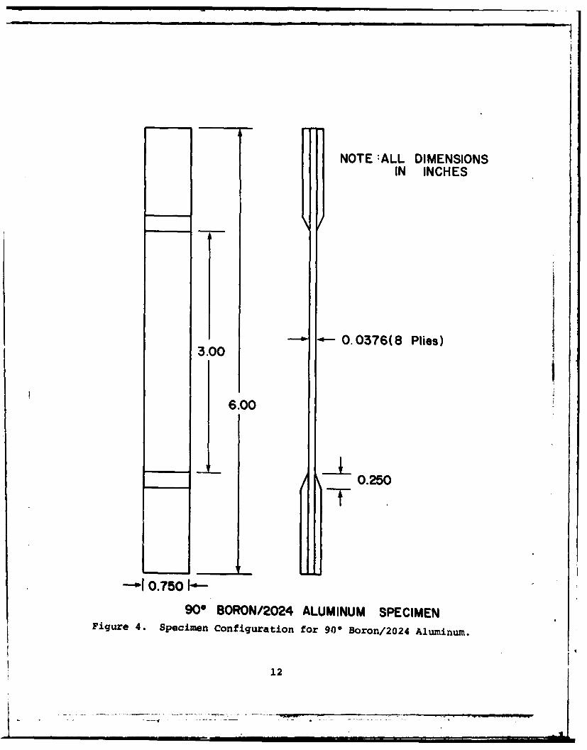
4 Specimen Configuration for 900 Boron/2024Aluminum. 12
5 Specimen Configuration for 0/900 StainlessSteel Wire Mesh/2024 Aluminum. 13
6 Specimen Configuration for 100 Off-Axis Boron/2024 Aluminum. 16
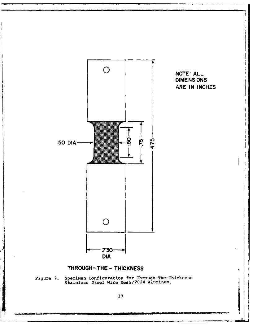
7 Specimen Configuration for Through-The-ThicknessStainless Steel Wire Mesh/2024 Aluminum. 17
8 Specimen Configuration for Rod Torsion StainlessSteel Wire Mesh/2024 Aluminum. 18
9 Specimt. Configuration for Rod Torsion Boron/2024 Aluminum. 19
10 Specimen Configuration for + 450 StainlessSteel Wire Mesh/2024 Aluminum. 21
11 Test Fixture Used to Test All Flat Specimenswith Specimen Installed. 23
12 Entire Test System Used to Conduct All Testsfor This Report Except the Rod Torsion Tests. 24
13 Test Fixture for Through-The-Thickness Specimenwith Specimen Installed. 26
14 Test Fixture for Rod Torsion Tests Shown withSpecimen Installed. 27
vi

LIST OF TABLES
TABLE PAGE
1 COMPOSITE MATERIAL TEST MATRIX 3
2 AVERAGED ELASTIC MECHANICAL PROPERTIES FORB/2024 Al and SSWM. 33
3 RESULTS FROM 0- B/Al MODIFIED IITRI SPECIMEN 34
4 RESULTS FROM 90- B/Al MODIFIED IITRI SPECIMEN 34
5 RESULTS FROM 0/900 SSWM MODIFIED IITRI SPECIMEN 35
6 RESULTS FROM THE THROUGH-THE-THICKNESS SPECIMEN 35
7 RAW AND REDUCED DATA FROM + 450 SSWM SPECIMEN 36
8 RECORDED AND REDUCED DATA FROM 100 OFF-AXISB/Al SPECIMENS 37
9 RECORDED DATA AND CALCULATED RESULTS FROM TORSIONROD SPECIMEN 38
viI
vii iI
5.

SECTION I
INTRODUCTION
Foreign objects (ice balls, ice spears, and small birds)
cause considerable damage when they impact jet engine fan blades
at particular angles and velocities. Rapialy rising material
and production costs make repairs quite expensive. Such costs
also make experimentation with new blade designs and materials
excessively expensive. This necessitates the developments of
design techniques (for designing foreign object damage [FaD]
resistant fan blades) that require minimal testing of actual
parts prior to determining the optimum combination of blade
shape and material properties. An FOD contractual effort aimed
at providing the described design capability has concentrated
on two items: (1) producing a fan blade analytical model and
(2) understanding FOD failure mechanisms. The availability
of these techniques will greatly enhance the possibility of
using composite materials in jet engines (which is desirable
because of their high strength to density ratio).
The fan blade analysis model requires as an input the
mechanical properties of the material used in the modeled blade.
In the present FOD research program three existing blades were
studied: the J-79 blade, the F-101 blade and the APSI blade.
As part of the research, the mechanical properties were obtained
for the materials involved: 410 stainless steel (used in the J-79
blade), 8A1-lMo-lV titanium (used in the F-101 blade), and
boron/2024 aluminum and stainless steel wire mesh (both used
in the APSI blade). The tests on the two metallic materials
were conducted at several strain ratios are discussed in the
* report entitled "Material Characterization: Part A". The
present report, "MaterIdl Characterization: Part B", contains
* a discussion of the mechanical property tests of the two metal
matrix composite materials.

Although the hybrid composite APSI blade has a complex ply
construction, the mechanical properties presented in this report
were obtained using simplified specimens made with the most
basic fiber configuration for each material. The unidirectional
boron aluminum specimens supplied these elastic parameters:
El, E2 (=E3 ), V1 2 ' G1 2 (=G3 1 ), and G2 3. The 0 and 900 "uni-
directional" stainless steel wire mesh (SSWM) specimens gave
values for E1 (=E2 ), E3, v1 2 ' G1 2' and G2 3 (=G31 ). Laminate
theory can be used to calculate the bulk properties of the blade
which has the following ply layup: SSWM/0° B-Al/22* B-Al/0 ° B-Al/
-22- B-Al/SSWM/Al/SSWM/-22- B-Al/00 B-Al/220 B-Al/0 ° B-Al/SSWM.
The matrix material in both composite subsystems was 2024 aluminum.
The bulk properties were not calculated for this report. The
tests were conducted at one strain rate, 0.001 strain/second,
because based on research conducted by Krinke, Barber, andNichola(1 )
Nicholas~ the assumption was made that these composite materials
would not be strain rate dependent. The materials tested had
approximately a 40 percent fiber volume content.
2

+i
SECTION II
DEFINITION OF THE TEST MATRIX
This section contains a discussion of several criteria
used to establish the test matrix for the composite material
tests. The matrix appears in Table 1. Items considered
include the availability of laminate theory, a previous study
of the strain rate dependence of boron/6061 aluminum, and the
selection of technically acceptable test specimen configurations
and instrumentation.
TABLE 1. COMPOSITE MATERIAL TEST MATRIX
FiberMaterial Specimen Orientation Parameter
Configuration to Load Axis Obtained
Boron/ IITRI 00 El, V1 22024 Aluminum O 900 E2 (=E3)
10* off-axis 100 GI2(=G31 )
Torsion 900 G2 3
Stainless IITRI 0/900 E1 (=E2 ), v12Steel WireMesh/2024 +45° +450 G12Aluminum Through-the- 900
thickness
Torsion 900 G2 3 (=G31 )
2.1 LINEAR LAMINATE THEORY
Linear laminate theory utilizes the properties obtainedfrom unidirectional composite specimens to predict section
properties of more complex fiber lay-ups. The hybrid composite
APSI blade readily lends itself to the use of laminate theory
for two reasons. First, the blade consists of two metal matrix
composites: stainless steel wire mesh-2024 atuminum (SSWM) and
boron-2024 aluminum (B/Al). The complex ply sequence follows
for half of the blade thickness (where SSWM was the outer most
I3.- Now

ply): SSWM/00 B-Al/220 B-Al/00 B-Al/-22°B-Al/SSWM/Al. The
remaining half of the blade is a mirror image of this sequence.
Second, as can be seen from the preceding sequence, the lay-up
of the B/Al was not simple either.
Both the SSWM and the B/Al are anisotropic materials which
implies that the mechanical properties each must be independently
obtained in relation to all three principle directions. Figures
1 and 2 show schematics of the fiber and ply orientation with
respect to the material principle axes of the B/Al and the SSWM,
respectively. Three normal and three shear directions are
indicated. The two paragraphs that follow discuss the fact that
both composite materials exhibit some symmetry. This eliminates
the need to test individually for all the following elastic
parameters: E1 , E2, E3, G1 2, G2 3 , and G31.
The diagrams in Figure 1 represent the boron aluminum.
A load applied in the one direction yields mechanical properties
that are primarily influenced by the boron fibers. Properties
obtained by applying a load in either the two or three direction
would be characteristic of the matrix material, 2024 aluminum.
In other words, E2 = E3 for this material. Similarly, G1 2 and
G31 are assumed to be equal because the properties of the fibers
in the test specimens predominate over those of the matrix. In
the B/Al, G23 is primarily representative of the matrix material.
The diagrams in Figure 2 represent the stainless steel
wire mesh. For this material the characteristics of the stain-
less steel fibers predominate for loads applied in the one and
two directions. Assuming that the warp and fill direction
fibers have the same configuration then E1 = E2 for _his material.
The matrix material, 2024 aluminum, has prime influence on E3.
The assumption that G23 = G31 for this material comes from the
symmetry provided by fibers in both the 0* and 900 directions.
G12 must be calculated from a separate test.
4
: " ... -.. I - - iI. . . - : : Ii

-2 NORMAL2 DIRECTIONSFIBERS
SHEARDIRECTION
FIBERS
BORON/2024 ALUMINUMFigure 1. Principal and Shear Directions Relative to Boron/
2024 Aluminum Unidirectional Specimens.
5

3
12 NORMAL4 4DIRECTION
. .FIBERS
PLIES
3
2
.3 SHEARDIRECTION
f ..FIBERS• 1 2 .-I / - - - - - PLIES
STAINLESS STEEL WIRE MESH
Figure 2. Principal and Shear Directions Relative toStainless Steel Wire fesh UnidirectionalSpecimens.
6

In summary, the partial symmetry in each of the materials
reduced the types of specimens required to obtain the desired
mechanical properties of these materials. The parameters El.
E2 1 V1 2 G1 and G2 needed to be independently obtained for
the boron aluminum while Elf E3 ' v1 2 ' G 12 ' and G 23 had to be
acquired for the stainless steel wire mesh.
2.2 RATE OF TESTING
The influence of strain rate on the mechanical properties
of fan blade materials is an important consideration in FOD
studies because of the range of strain rates produced in the
blade by a variety of impact loads and velocities. The metallic
material characterization tests, discussed in Part A of this
report, were conducted at several testing rates. Most of their
mechanical properties depended to some extent on the testing
rate. However, the composite material characterization tests
described in this volume (Part B) of the report were to be
conducted at one testing rate. The following paragraphs
describe the reasons for that decision.
The fabrication costs of metal matrix composite specimens
prohibit unnecessary extensive testing of the subject materials.
An inspection of various suis(1,2,3,4) revealed that the
mechanical properties of these material systems (boron, several
B/Al composites, and several aluminum alloys) were not strain
rate dependent at ambient temperatures (720 to 750F) over several
decades of strain rate. The first three investigations describe
conventional tension and/or compression tests conducted on uni-
directional boron composites~1 2 or on aluminum alloys 3 . The
tests encompassed six decades of strain rate (10- to 10 2strain/
sec) and all indicated little or no strain rate dependence of
the materials involved. The fourth study (by Krinke, Barber and
Nicholas), described below because the three point bend tests
used are not conventional mechanical property tests, also indicated
no significant strain rate dependence over six decades of strain
7

rate. Based on the cited works (concerning boron and aluminum)
and discussions with the sponsor of the current effort (in which
the sponsor indicated that they did not expect the SSWM to be
strain rate dependent) the University decided to conduct the com-
posite material characterization tests at the strain rate of
1 strain/sec. While running the tests it was decided that a
strain rate of 0.001 strain/sec was more desirable.
The purpose of the Krinke work was to evaluate the Charpy
impact test as a method for screening composite materials for
impact resistance. Three point bend tests conducted on three
materials (boron/6061 aluminum, boron/llO0 aluminum, and
graphite/epoxy) provided load-deflection curves and energy
absorption data. The data, obtained at three displacement rates
(0.002 in/sec, 1 in/sec and 100 in/sec), was compared to stresses
and deflections predicted by strength of materials formulas and
by more sophisticated theory of elasticity solutions. For
additional information from the study, the ultimate bending
strength and the energy absorption were both plotted versus
strain rate. Since only one test was conducted per material
per specimen depth per testing rate, the data showed considerable
scatter. A plot of the averaged ultimate bending strength (from
tests on specimens of different thicknesses) versus strain rate
for the three materials showed a general trend of a slight
increase in bending strength for an increase in strain rate.
The rate of increase was about 1 percent per decade of strain
rate for the boron/6061-aluminum and 2 percent per decade of
strain rate for the boron/llOO-aluminum. The conclusion reached
in the present study about the Krinke work was that the rate ofincrease of the ultimate bending strength with strain rate was
insignificant for the boron/aluminum materials over the tested
range of six decades of strain rate.
As indicated above, the University planned to execute the
test matrix shown in Table 1 at the displacement rate of 1 in/sec.
This displacement rate corresponds to strain rates between 0.33
and 2 strain/sec for the various specimen configurations,
8

depending on the specimen gage length. A few tests on boron
aluminum were conducted at this rate. However, mechanical
properties significantly lower than expected were calculated from
the results. Consequently, several tests were conducted at a dis-
placement rate of 0.001 in/sec to enable close observation of the
specimen during the test. Comparable values were obtained for
both rates so the remainder of the tests were conducted at the
slower rates for two reasons. First, each specimen could be
closely observed during the entire test. Secondly, the datacould be recorded directly on the X-Y recorders, thus producing
smoother curves (than can be obtained from data recorded digitally
and played back) for data analysis purposes.
2.3 SPECIMEN CONFIGURATION AND INSTRUMENTATION
The following paragraphs describe and justify the specimen
configurations selected to obtain the parameters specified in
Table 1. The included specimen illustrations have the nominal
dimensions indicated. The transducers used to measure the
strains (various high resistance foil strain gages) on each
specimen type are mentioned. The analysis of the data is
briefly described in Section IV.
2.3.1 Modified IITRI Specimen
A modified IITRI (Illinois Institute of Technology
Research Institute )specimen was used for three test types:
the 00 B/Al, the 900 B/Al, and the 0/900 SSWM. The Structural
Design Guide for Advanced Composite Applications recommends
the IITRI configuration for obtaining unidirectional mechanical
properties of composite materials. The fibers in the IITRI
specimens are parallel and/or perpendicular to the applied
load. The Guide indicated that the specimen is particularly
4 useful for testing organic matrix composites. Consequently,
the University assumed that the configuration was also acceptable
for testing metal matrix composites. For the current program
the following two modifications were made (and justified by
the fact that the matrix material was metallic rather than
9-

organic): (1) the specimens were 6 inches long rather than the
Design Guide recommended 9 inches long and (2) the specimens
were a nominal 3/4 inch wide rather than the Guide recommended
1 inch. The specimens used appear in Figures 3, 4, and 5 with
nominal dimensions specified. These specimens were all in-strumented on both sides with Micro-Measurements two element
high resistance foil gages EP-08-125VB-120. The 0°B/Al specimen
provides E1 and v12 (where 1 and 2 refer to material-axes
orthogonal coordinate system with 1 taken along the fiber
direction), the 90°B/Al provides E2 (=E3 ), and the 0/900 SSWM
provides E1 (=E2 ) and V1 2.
2.3.2 Modified 100 Off-Axis Specimen
The 100 off-axis specimen (5 ) was selected to obtainthe intralaminar shear modulus stress for boron/aluminum
material. The recently developed specimen had several advan-
tages over previously used specimens for intralaminar shear
characterization. The discussion that follows includes (1) an
indication of the origin of the specimen and the quality of
results obtained from it, (2) a listing of some of the advantagesand the disadvantages to using the specimen, and (3) the reasons
the University selected the specimen for the test program
described in this report.
The specimen was developed and proposed by IITRI
during a contractual study with NASA Lewis Research Center. A
subsequent in depth theoretical and experimental investigation(5 )
yielded a satisfactory comparison of experimental and predicted
curves. The results of that study prompted a recommendation
that the specimen be considered as a standard test for intra-
laminar shear. The advantages of this specimen that were
relevant to the current test program follow:
1. The specimens have uniform shear stress through thethickness.
2. The specimens are free of lamination residual stressesin contrast to the + 450 specimen.
3. The use of the thin laminate narrow specimens savesconsiderable material (compared to thin tubes).
10

-=ME
NOTE: -ALL DIMENSIONSIN INCHES
0-.0376 (8 Pies~)3.00
6.00
- 0.250
-j0.750 -40 BORON/2024 ALUMINUM SPECIMEN
Figure 3. Specimen Configuration for 00 Boron/2024 Alumtinuma.
NOTE :ALL DIMENSIONSIN INCHES
0.0376(8 Plies)
3.00 I6.00
0.250-T
-10.750 -900 BORON/2024 ALUMINUM SPECIMEN
Figure 4. Specimen Configuration for 900 Boron/2024 Aluminum.
12
! -1 - -

NOTE :ALL DIMENSIONSIN INCHES
----0.0752 (16 Plies)3.00
6.00
I
0.250TI-- 0.750 F-
0/900 STAINLESS STEELWIRE MESH SPECIMEN
Figure 5. Specimen Configuration for 0/900 Stainless SteelWire ,.esb/2024 Aluminum.
13
I-1------I--I I IiI
! | III I I. . .. . ... ... ...... .. .. .. ."' " " yI

4. The specimens can be cut from the same laminate usedto obtain specimens for longitudinal and transverseproperty characterization.
5. The use of a familiar tensile test procedure.
The disadvantages to using the specimen include:
1. An increase amount of data reduction calculations.
2. Increased care in aligning the specimen in the fixtureand aligning the strain gages on the specimen.
The results of another study ()which compared mechanical
properties obtained from six different intralaminar shear
specimen configurations were not as promising. However, the
University of Dayton gave more weight to the study in Reference
5 because it was much more extensive experimentally and analyt-
ically than the Reference 6 study. The experiments for Reference
5 were conducted on three different materials whereas those for
Reference 6 were conducted on one. Reference 6 contained no
analysis of the specimen configuration. It contained only the
results of data reduction.
Several factors strongly influenced the University's
decision to use the specimen configuration. First, the advan-
tages listed above made the specimen quite attractive. Second,
predictable results had been obtained for the majority of tests
conducted using the specimen. Third, the disadvantages to
using the specimen were merely inconveniences. They were not
problems associated with the fundamental design of the specimen
which would produce erroneous results. Fourth, the program
described in this report was to test metal matrix composite
materials. Since all of the test cited above were conducted
on epoxy based composites and most of them yielded acceptable
and predictable results, the University anticipated that the
specimen might be even more acceptable for testing metal matrix
composites. Discussions of this latter point with T. Hahn and
J. Whitney~7 (both of whom were at the Air Force Materials
Laboratory at that time) reinforced the opinion that the specimen
should work well with metal matrix composite materials.
14

The modified 100 off-axis specimen appears in
Figure 6. The modifications, a 4 inch reduction in length and
a 3/8 inch reduction in width, were justified by the fact that
the matrix material was metallic rather than organic. B/Al
specimens of the reduced size had been tested and predictable(8)
results obtained (8 The specimens were instrumented with two
Micro-Measurements, three element rosette strain gages, EA-08-
125VB-120, placed back to back to cancel bending. The specimen
provides G1 2 for the B/Al.
2.3.3 Through-the-Thickness Specimen
A through-the-thickness specimen was designed to
obtain the elastic modulus in the interlaminar (E3 ) direction
for the SSWM. The specimen appears in Figure 7. It was made
by removing coins, a nominal 0.750 inches in diameter from a
136 ply thick la'up of SSWM. (The fibers were perpendicular
to the load axis.) Two inch long aluminum rods were attached
to each end of the coin with a resin bond adhesive to provide
an area to grip the specimen. Dowel pins through the holes in
the grip section fasten the specimen in the test fixture. A
reduced section was cut on the SSWM portion of the specimen.
The specimen was instrumented with two Micro-Measurements EA-
08-125AD-120 (single element) gages placed diametrically
opposite each other and aligned with the direction of the
applied load.
2.3.4 Torsion Rod Specimen
A torsion rod specimen was used to obtain the
interlaminar shears G23 for the B/Al and G31 (=G2 3) for the
SSWM. The specimens appear in Figures 8 and 9, respectively.
They were made by removing coins, a nominal 0.700 inch in
diameter, from a 135 ply thick layup of each material. Three
of the coins (of one material) were diffusion bonded together
to form a specimen having the fibers perpendicular to the long
axis of the specimen. Four inch long aluminum bars were
attached (resin bonded) to the fused specimens for use as grips.
15'

NOTE:ALL DIMENSIONSIN INCHES
O.0376(8PIies)3.00
6.00
0.250
I l .,- 0.375100 OFF-AXIS SPECIMEN
Figure 6. Specinen Configuration for 100 Off-Axis Boron/2024 Aluminum.
16
, I - -- -v I I -- ia -- U
of NOTE: ALL
DIMENSIONS
ARE IN INCHES
.50 DIA
I A
0
.730----
DIA
THROUGH-THE- THICKNESS
Figure 7. Specimen Configuration for Through-The-ThicknessStainless Steel Wire Mesh/ 2024 Aluminum.
17

NOTE: ALLDIMENSIONSARE IN INCHES
T
00
.00
H F-
DIA
STAINLESS STEEL WIRE MESHTORSION ROD
Figure 8. Specimen Configuration for Rod Torsion StainlessSteel Wire Mesh/2024 Aluminum.
18

0NOTE: ALLDIMENSIONSARE IN INCHES
7-
II
.0DIA
BORON/ALUM I NUMTORSION ROD
Figure 9. Specimen Configuration for Rod Torsion Boron/2024Aluminum.
19
.. -: _ _' " ' ':-- " . . .. ;._--::. -______,_,_--_____.___,__,____________,_,_________...._-_-____----__---______,_____.. ........ _

The ASTM standard for torsion tests (E143) was consulted to
determine the required length of the rods (so that one can
assume that a uniform stress field exists in the test section).
A dowel pin through the hole in each grip section fastens the
specimen in the test fixture. A Micro-Measurements torsion
gage, EP-08-125TD-120, was used on the specimen to obtain the
strain data.
2.3.5 ± 450 Specimen
The standard + 450 specimen was an obvious choice
to obtain the intralaminar shear stress of the SSWM material
because of the nature of the mesh. The specimen, shown in
Figure 10, varies from the IITRI configuration (described
above) only by the fiber direction. The nominal dimensions
appear in the figure. The specimens were instrumented on both
sides with Micro-Measurements two element foil gages, EP-08-
125VB-120. The specimen provides G1 2 for the SSWM.
20
I. .

_ .. II ltI
NOTE" ALL DIMENSIONSIN INCHES
0.0752 (16 Plies)3.00
6 00
0.250
L--V
1.00
±45° STAINLESS STEELWIRE MESH SPECIMEN
Figure 10. Specimen Configuration for + 450 Stainless SteelWire tlesh/2024 Aluminum.
21
..- , . . . .. .

!1
SECTION III
TEST FIXTURES AND EXPERIMENTAL PROCEDURES
This section contains photos of the test fixtures and
system and discusses the experimental procedures for each test
type. The test fixture and procedure descriptions are grouped
under three headings. Each group comprises the test
types conducted with one of three different test fixtures.
Each of the specimens, except for the torsion rod specimens,
had two high resistance foil strain gages applied directly
opposite each other to cancel any bending that might be present.
The torsion rods had only one torsion gage applied. Each set of
two individual gages (i.e., two Poisson, or two longitudinal,
or two diametrically opposed elements of the three element
rosette) was wired into two opposite legs of a Wheatstone Bridge
circuit. The signal conditioner for the bridge output was a
218 Honeywell Bridge Amplifier. The medium rate load and strain
data was recorded on the four channel transient Zonic recorder
and played back onto the X-Y recorder. The quasi-static tests
data was recorded directly on the X-Y recorder.
General Electric Company supplied the composite material
specimens. The University measured the widths and thicknesses
or the diameters of all specimens. These values were used in
stress calculations and to document the uniformity of the
specimens.
3.1 TEST FIXTURE AND PROCEDURES FOR THE 00 B/Al, 900 B/Al
0-900 SSWM, 100 Off-Axis B/Al, + 450 SSWM SPECIMEN
The 00 B/Al, 900 B/Al, 0-900 SSWM, 100 off-axis B/Al,
and + 450 SSWM specimens, all flat ones having aluminum tabs,
were tested in the fixture shown in Figure 11. The test system
consists of a set of Instron grips mounted in an electrohydraulic
closed-loop test machine. The complete test system including
the MTS control console appears in Figure 12. This test system
22

Figure 11. Test Fi:ture Used to Test All Flat Specimens WithSpecimen Installed.
23
-- 7-

4)
x
4-Is-I0
E-4a4
0~4-w
-i
-I
0
41
ulw
aE-44-)
wo
E*4
24a
I .E
!
has the capability of being operated in load, strain, or dis-placement control. The tests described here were run in dis-placement control. Two of the 0* B/Al tests were conductedat a displacement rate of 1 in/sec. The loads obtained wereconsiderably smaller than had been expected. In resolving theproblem a couple of tests were conducted at 0.001 in/sec.Values similar to those for the faster rate were obtained,consequently the remainder of the tests were conducted at theslower rate.
3.2 TEST FIXTURE AND PROCEDURES FOR THE THROUGH-THE-THICKNESSSPECIMENS
The fixture to test the through-the-thickness specimensappears in Figure 13 with a specimen installed. Dowel pinsprovide the mechanism for load application. All of thesetests were run at a displacement rate of 0.001 in/sec. Thecontrol console and recording apparatus shown in Figure 12completed this test system.
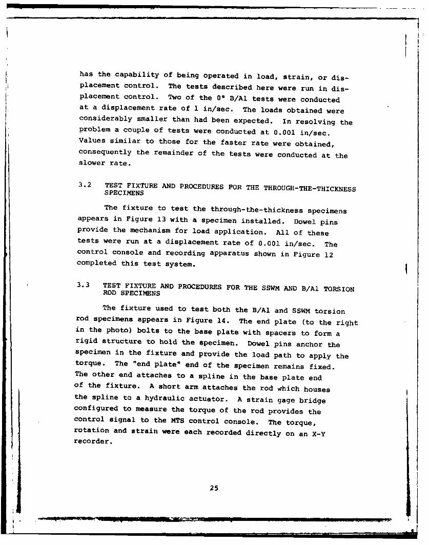
3.3 TEST FIXTURE AND PROCEDURES FOR THE SSWM AND B/Al TORSIONROD SPECIMENS
The fixture used to test both the B/Al and SSWM torsionrod specimens appears in Figure 14. The end plate (to the rightin the photo) bolts to the base plate with spacers to form arigid structure to hold the specimen. Dowel pins anchor thespecimen in the fixture and provide the load path to apply thetorque. The "end plate" end of the specimen remains fixed.The other end attaches to a spline in the base plate endof the fixture. A short arm attaches the rod which housesthe spline to a hydraulic actuator. A strain gage bridgeconfigured to measure the torque of the rod provides thecontrol signal to the MTS control console. The torque,rotation and strain were each recorded directly on an X-Yrecorder.
25

Figure 13. Test Fixture for Through-The-Thickness Specimen
With Specimen Installed.
26
_ m lia l mnm n n I • u---- Iii
EI
4
4.)
E-4
0
0-
4
E4
27z

SECTION IV
DATA REDUCTION
This section contains the data reduction relationships for
the various test types. The parameters calculated using data
from the appropriate test include the elastic modulus, the
ultimate strength, the ultimate (percent) strain, the shear
modulus and Poisson's ratio. In all cases engineering param-
eters were calculated (rather than true stress and strain).
The reduced data appears in Section V.
4.1 MODIFIED IITRI SPECIMEN (00 B/Al, 900 B/Al, and 0/900 SSWM)
The data reduction for the 00 and 900 B/Al and the 0/900
SSWM was straightforward. The elastic modulus, the ultimate
strength, the ultimate strain (percent), and Poisson's ratio
for the 1 and 2 material directions were calculated using the
following relationships:
e =PAEl(and 2) C e e
Pmaxault A
Cult (%) = Ce(max) x 100
V Et
12 c
where: E = elastic moduli in the 1 and 2 material direction
ae = engineering stress
Ce = engineering strain in the longitudinal direction
P = load
Pmax = maximum load
28
eI

A = crossectional area of the specimen
C ult = ultimate strain in percent
v = Poisson's ratio
Ct = transverse strain
£E = longitudinal strain
E1, E2, ault E(%)ultl, Gult2' '(')ult2, v12 , and v21 were cal-
culated for the B/Al from these tests. E1 (=E2) , aultl (=Oult2),
F-(%) ultl (=c(%) ult2 ), and v12 (=v21 ) were calculated for the SSWM.
4.2 + 450 SSWM SPECIMEN
Data reduction for the + 450 SSWM specimen yields the
intralaminar shear modulus, G1 2 . P.H. Petit (9 ) presents relation-
ships that utilize elastic constants from uniaxial tests in the
transverse and longitudinal directions in addition to the
tangent modulus, and the longitudinal and transverse strains
of the + 450 stress-strain curves. An incremental shear stress-
strain curve for the constituent laminae results from the
calculations. The equations follow:
2U1 E±45G = xx12 8UI x
x
and AT12= G1 2 y1 2
where U 1 =8(1- 12 v21) [E1 + E2
+ 2v21 E1 1.
E2and V2 1 =V 2
29

!I
However, E1 and E2 were assumed to be equal for these experi-
ments so V21 = V12 and U 1 = E 1/4(1 - v12). (All of the data
was obtained from laminates of the same thickness consequently
the fiber volume was the same for the unidirectional and + 450
data, an important factor in the use of these equations.) The
shear modulus was the initial tangent of the incremental shear
stress-strain curve.
4.3 THROUGH-THE-THICKNESS SPECIMEN
The data reduction for the through-the-thickness specimen
was straightforward. The parameter of interest was E3 for the
SSWM. The equations follow:
-Y P/A
3 e e
where: E3 = elastic modulus in the three material direction
ae = engineering stress
e = engineering strain
P = load
A = crossectional area of the specimen
The ultimate stress and strain couldn't be calculated for these
specimens because they failed at the bond between the tab end
and the test specimen section. Poisson's ratio could not be
calculated for this specimen because it was not possible to
locate the exact orientation of the fibers in the specimen,
i.e., one could not determine the location on the circumference
to place the longitudinal and transverse strain gages.
4.4 100 OFF-AXIS SPECIMEN
The 100 off-axis specimen provides data to calculate
G12 for the boron aluminum material. The equation relating the
strain gage strains to the structural axes (x and y of the
specimen) strains follows:
30
-V- . _

e 052 6 s2 0 sin 28
g 0g1 Sin0l 2 2 gl cxxEg Cos 2g I sin 2 8 g sin 2cg2 g2 g2 2 g2 cyy
g3 c 2 g3 g3 2 g3 cxy
where: c C E 3 denote the true (measured strains correctedgl g2 g3 for gage transverse sensitivity) strainfrom gages 1, 2, and 3 respectively.
gl' 6g2' 6 g3 denote the corresponding orientation anglesmeasured from the load directions
Ccxx E cyy, Ccxy denote the structural axes strains
The equationE£12 = (Ccyy - cxx ) sin 28 + E cxy cos 20
relates the structural-axes strain to ply intralaminar shear
strain for any orientation e. The equation relating the ply
intralaminar shear stress to the structural-axes stress is:
a £12 = 0.171 acxx .
These equations appear in Reference 5 with a more detailed des-
cription of their development.
The gage configuration for the tests conducted for this
report was 6gl = 1350, g2 = 900, and 8g3 =45 . Inserting
these values in the coefficient matrix above and reducing
the equations results in the following equations for intra-
laminar shear strain:
£12 = -1.282 egl + 0.684 cg2 + 0.59 kg3*
The intralaminar shear stress-strain curve was generated as
follows: For each load increment,
31
(1) Use the equation immediately above to calculate E.12
(2) Use the equation preceeding that to calculate Ol2
(3) Plot a L12 against E 1 2 for each load increment
The initial ply shear modulus, G12' was determined from the
slope of the initial tangent to the curve generated in (3).
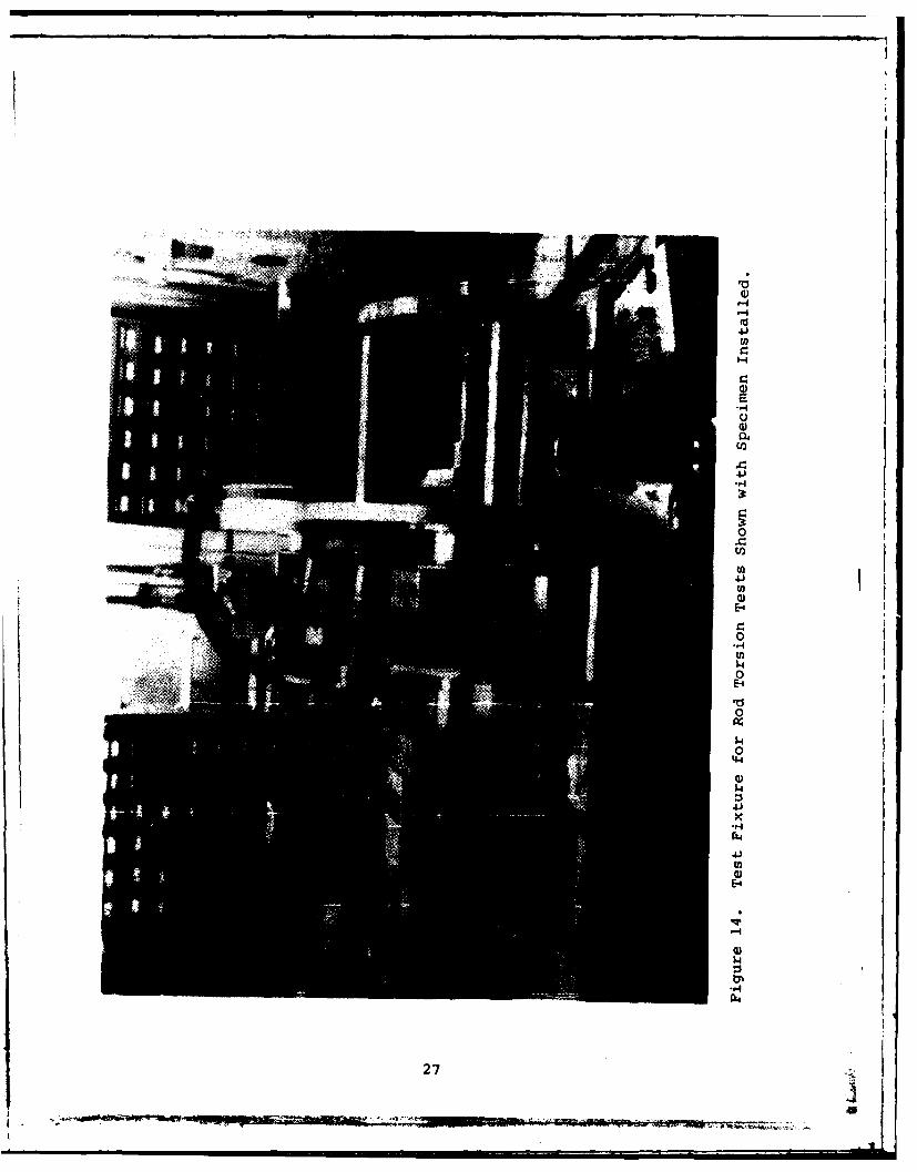
4.5 TORSION ROD SPECIMENS
The relationship for reducing the data from the rod torsion
tests was derived using Saint-Venant torsion theory. (The ex-
tension rods attached to the test section of the specimen were
long enough that one could assume a uniform stress distribution
in the test section.) The equation used was:
2__ TL+ 1 G12 J8
where: = /G12
T = applied torque
L = length of rod section to which the torque wasapplied
G12 = shear modulus on a plane
J = polar moment of inertia of the specimen crosssection
e = angle of twist, in radians
G12 was obtained for both the B/Al and SSWM from a separate
test, consequently, the above equation yielded G23 for each
of the materials.
32

SECTION V
RESULTS AND CONCLUSIONS
This section presents and discusses the test results. The
calculated mechanical properties obtained from the test data
for the B/Al and SSWM appear in Tables 2 through 9. Tables 6
and 7 also contain recorded data points and the points of an
incremental stress-strain curve generated from the recorded data.
Table 2 summarizes the results by presenting the primary and
shear moduli and Poisson's ratio for each of the materials.
Most of the values in Table 2 represent the average of the
results of three tests. The materials tested had a fiber volumecontent of approximately 40 percent.
TABLE 2. AVERAGE ELASTIC MECHANICAL PROPERTIES FOR B/2024 AlAND SSWM/2024 Al.
mechaicalMaterialProperty I B/Al SSWM
1 27.0 xl10 psi 15.3 x10 6psi
E215.7 x 10 6 psi 15.3 x 10 6 psi
E 3 15.5 x 10 6psi 1.5 x 10 6psi
G6.9 x 106 psi 5.6 x 10⁶ psi
G3 6.9 x 10⁶ psi 1.5 x 10⁶ psi
V 2 .12 .31
Some of the mechanical properties for the B/Al did not
compare well with values found in the literature. Some of the
values obtained here were comparable to literature values. The
elastic moduli in the one and two material directions were
33
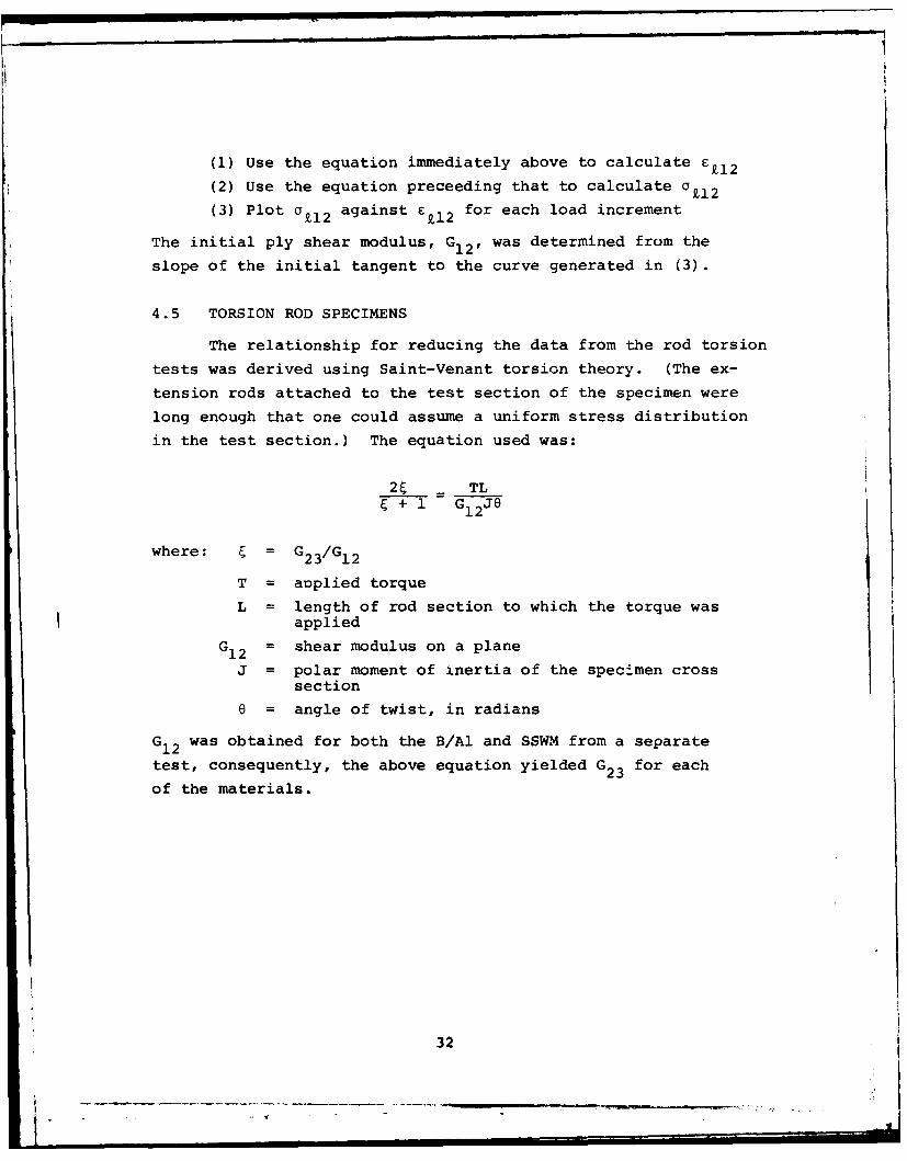
TABLE 3. RESULTS FROM 0 B/Al MODIFIED IITRI SPECIMEN
El Ultimate Ultimate v1 2Specimen Modulus Strength Strain Poisson's
(psi x 106) (psi x 103) (percent E) Ratio
B4-1 27.7 56.4 0.26 *
B4-3 25.6 * * 0.23
B4-2 28.2 47.0 0.18 0.23
B4-4 26.6 58.9 * 0.25
* Not Available
NOTE: Ultimate strength and strain were calculated usingthe maximum load and strain at failure. Failureoccurred near the tab, about one inch from thestrain gage location so the actual fracture strainwas larger.
TABLE 4. RESULTS FROM 900 B/Al MODIFIED IITRI SPECIMEN
E2(=E 3) Ultimate UltimateSpecimen Modulus Strength Strain Poisson's
(psi x 106) (psi x 103) (percent e) Ratio
B6-2 15.7 17.2 0.20 0.139
B6-3 16.0 18.6 0.27 0.148
B7-2 15.5 18.7 0.27 0.08
NOTE: Ultimate strength and strain were calculated usingthe maximum load and strain at failure. Failureoccurred near the tab, about one inch from thestrain gage location so the actual fracture strainwas larger.
34

TABLE 5. RESULTS FROM 0/900 SSWM MODIFIED IITRI SPECIMEN
EI(=E 2 ) Ultimate UltimateSpecimen Modulus Strength Strain Poisson's
(psi x 106) (psi x 103) (percent E) Ratio
M3-2 15.0 44.9 2.9 0.33
M2-1 15.6 46.3 2.8 0.28
M3-3 15.3 42.9 2.0 0.35
NOTE: Ultimate strength and strain were calculated using
the maximum load and strain at failure. Failureoccurred near the tab, about one inch from thestrain gage location so the actual fracture strainwas larger.
TABLE 6. RESULTS FROM THE THROUGH-THE-THICKNESS SPECIMEN
Specimen ModEuus
(psi x 106)
M7-1 6.2
M7-6 7.7
M7-8 7.5
NOTE: Ultimate strength and straincould not be obtained for thesetests because failure occurredat the resin bond between thetest section and the attachedgrip section.
35

' 4 %DODo 00 00 0c0 a I 0 0%0 00 0 00 -1 COr OD 40 0 00 a
-4 c~4 14 r.e4-4 C4 44W-1 m-% 4D .4w r
4 )4 u m 4%.4-~m04d~uw 44444444-~44444 ~ --- ~
Ll 00m0 00 14N 0 00000 sL0fmM0IA 00If4 4 N N4O
-4i 000000c 00000000000 00000000000
U 4 .4. *-4 Mn0 .4% 0 -0 A 0 M r_- 0 C D *m 4% -14 1- 0 %D r CI 0 0C 00w
44 14 4 4 ;C-1 4A44 ;C
Ca w~ 0cm N or- owe414 00 0ON owE4 oc4m 4f4W0.-4aW m 2 0% %
0 0% o2 r4.1M ' 4-M IfUIn r4C wM.-4oo~fWM MV 0 0
0 '4
40 4-'e~ 24
N 4
co Llo fon -w m flOm o a n a n mA lm fm M 0f~f OalflfqEl 0 w n0C0 a 4Ln O m rW 4 c r 0 % .4q v .4M*4 C n MC V..4 0 0w r. 4 O
.999C!99.0 w0 000C..*20Lf00.. 4M.W*M-t
1l 0 4 l "m -i w0 Nw %0- P-4N r4" mv n O %9. r4 m Nm w V
a, o4 "4 C' % 10 441,901 0r
-.4 44 4
36

TABLE 8. RECORDED AND REDUCED DATA FROM 100 OFF-AXIS B/AlSPECIMENS.
RECORDED DATA REDUCED DATA____ 2 2 Eg ____
SPECIMEN I 22 Eg3 CY12 F£12
lbs PE_ _ _ c c psi ___
B2-1 100 212.5 - 100 +125 948 - 133200 412.5 - 225 +250 1895 - 267300 625 - 344 +350 2843 - 414400 850 - 469 +465 3791 - 566500 1137 - 625 +575 4738 - 771
600 1500 - 825 +675 5686 -1042700 1962 -1112 +695 6634 -1430800 2550 -1500 +600 7581 -1968
B2-2 100 188 - 53 119 S50 - 105200 388 - 203 225 1900 - 249300 612 - 338 312 2851 - 415400 838 - 488 388 3801 - 588500 1125 - 688 425 4751 - 829600 1450 - 912 412 5702 -1118700 1875 -1200 325 6652 -1515
B2-3 100 238 - 125 112 941 - 144200 438 - 238 225 1881 - 388300 650 - 350 325 2822 - 417400 888 - 475 478 3763 - 613500 1188 - 612 531 4703 - 812600 1625 - 800 562 5644 -1147700 2112 -1088 500 6585 -1576
B2-4 125 200 - 175 +87.5 1201 - 162
250 450 - 375 187.5 2402 - 361375 750 - 950 225 4804 - 963625 1600 -1325 100 6005 -1449
750 2325 -1825 100 7206 -2085
SPECIMEN SHEAR MODULUS
6
B2-1 G2= 6.9x10⁶ psi
B2-2 G = 8.2x10 6 psi
B2-3 G = 5.9 x10⁶ psi
B2-4 G 6.7 x10⁶ psi
37
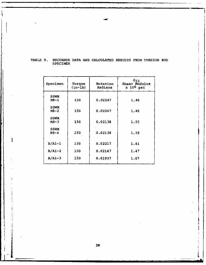
TABLE 9. RECORDED DATA AND CALCULATED RESULTS FROM TORSION RODSPECIMEN
G23Specimen Torque Rotation Shear Modulus
(in-lb) Radians x 106 psi
SSWMM8-1 150 0.02247 1.46
SSWMM8-2 150 0.02247 1.46
S SWMM8-3 150 0.02138 1.55
SSWMM8-4 150 0.02138 1.55
B/Al-i 150 0.02217 1.41
B/A1-2 150 0.02147 1.47
B/A1-3 150 0.01937 1.67
38 1

slightly below the literature values. No values for E3 were
found for comparison to the values here. The Poisson's ratios
compare well with literature values. In addition, v21 cal-
culated from the average values of v12 ' E1 and E2 was nearly
the same as the average of the v2 1 values obtained experimentally.
The shear modulus G1 2 (=G31 ) compares well with Reference 8. No
values were found for comparison to G2 3. The ultimate strength
obtained here was about one third as large as had been found in
the literature. The ultimate strain was smaller than literature
values; however, one would expect that because the specimens
failed near the tab, almost an inch away from the strain gage.
No ultimate shear strengths could be obtained because (1) the
intralaminar shear test specimens had premature tensile failures
and (2) the intralaminar shear tests were limited by the resin
bond.
It was not possible to compare the mechanical properties
obtained here for SSWM because no data for the material was
found in the literature. It should be noted that the ultimate
strain shown here was measured nearly an inch away from the
failure location (because the specimen failed near the tab).
The ultimate strength and strain could not be obtained from
the through-the-thickness tests because the specimen failed
at the resin bond. The intralaminar shear specimens did not
fail so no ultimate shear strength could be calculated. For
this material, as for the B/Al the intralaminar shear tests
was limited by the resin bond.
In conclusion, the mechanical properties obtained for the
B/Al indicate that the material tested for this study was dif-
ferent than had been tested in previous studies. No comparable
statement can be made about the SSWM because no data was found
in the literature.
39
-01--- V. . . . .- - - --

SECTION IV
REFERENCES
1. NASA CR-135086.
2. Meyn, D.A., "Effect of Temperature and Strain Rate on theTensile Properties of Boron-Aluminum and Boron-EpoxyComposites," Composite Materials Testing and Design (ThirdConference), ASTM STP 546, 1974, pp. 225-236.
3. Green, S.J. and S.G. Babcock, "Response of Materials toSuddenly Applied Stress Loads: Part I: High Strain-rateProperties of Eleven Reentry-vehicle Materials at ElevatedTemperatures," TR 66-83, Part I, November 1966.
4. Krinke, D.C., J.P. Barber, and T. Nicholas, "The CharpyImpact Tests as a Method for Evaluating Impact Re- stanceof Composite Materials," UDRI-TR-77-54.
5. Chamis, C.C. and J.H. Sinclair, "Ten-Degree Off-Axis Testfor Shear Properties in Fiber Composites," ExperimentalMechanical, September 1977, pp. 339-346.
6. Chiao, C.C., R.L. Moore, and T.T. Chiao, "Measurementsof Shear Properties of Fiber Composites Part 1, Evaluationof Test Methods," Composites, July 1977, pp. 161-174.
7. Private Communication with T. Hahn and J. Whitney.
8. Private Communication with C.C. Chamis.
9. Petit, P.H., "A Simplified Method of Determining In-PlaneShear Stress-Strain REsponse of Unidirectional Composites,"Composite Materials Testing and Design, ASTM STP 460,pp. 83-93.
40

4 0to .-4 %a WM 0 00 00 0 00 r, C4 00 0O%0 00 r400 - OV -4 0 0 0a0
4J0) 0400%00-; 4 c 4-;u;I (iWA 4 0. 4N L4 4 9 c 0%0 a; ( a;L
$4E0 r 9 O: E 0O O 0 wo mm oOo moom '40LAO %m oot OL OLAIALA0n ,-4 m
0, 4% DMmN aV0 Wr % 00N i Go0% 0 a, 14 co L Am -iv-i %
k4 -4 0 0 0 0 000 04 000-4,-1(4 O000. 4 -1-I ('4
0(0 *-4
4 J
H 014 - % L .a mow 0 -1 v w% ~m qw% ( o ('L n rm wou r-4 41 -.4 m(h 0 -4W0 %D -OO % r- V 0 M -4DW',-i r, Ln C t O(AO%0' lN 000 VAl o 0' "O 0
*(04 ('I ('4 -Wm-.4r4r;c 4, . r ; LU) k -4
W0 E - - _-4 .- 4 -,4
o0 -- -- --------- N ----- ----- C o -oo ON ::: U D %0 %0o o w L r-4r-i n m 4 m l0 CD C.)
> m2in o w w wwr- r- r-,- twc q owin % l % L %~o %0 u 0 -4 -4 -
-- -~x x
0R 00 n mDw4 ~w0NC'4"W0NOCqN W fWkDMOW-4 ON U) v N
-W Ox M -4 - '-4 -4 '- -f+ IX
4Jz
4-14 -4 C'4
U4L 0Mr W -0 - r4Vr 4MWWt 0MW m0w"00wf -1 r- m 0
0 ~000 00000000MLAW 0004-I-0 r) NO 0 0 '4(4 0in-0% (
0 0 40 0 0 0 OLA0 '4 4 0 0 0 0 0 0 0u0 0r4 - 0,-40C'Jr.r bO.0W.- 400: 0 000000 0 00000c ).0 00 0000 0 0000 00 a0 00Q00
. . . . . . . . . . . . . . . . .
.4 %~.- 0%4 N O%0N00E0%404.- 00%(4 ,tofWA OD00.4 COe 00 H ON r- %I- %0 tn w r %a % o%P- r- Dc4 % cc 0 4MO O~' m fIVr we
Oiu -0 4 0w 4 mLn oen %W c a% -in r w rOqe.%oco m4 v' i co -4 %
4.41
2:V

ATE
LME


![AP English Literature and Composition and Composition ...skipnicholson.net/APSI/APSI 2016/Canada/Nicholson Canada.pdf · [1] The course includes intensive study of works such as those](https://static.documents.pub/doc/80x56/5eaddb4800dfca486d3c35cc/ap-english-literature-and-composition-and-composition-2016canadanicholson.jpg)


