28
OPERATIONS MANUAL FOR “KNOT TO WORRY” Owners Gary and Sherri Joiner Anacortes, WA
OPERATIONS MANUAL
FOR
“KNOT TO WORRY”
Owners Gary and Sherri Joiner Anacortes, WA
Welcome aboard KNOT TO WORRY! We are excited you’ve chosen to charter “KNOT TO WORRY” for your vacation in the beautiful islands of the Pacific Northwest. You are about to embark upon a vacation that you will remember forever!! The San Juan Islands offer some of the most spectacular scenery you will ever see. Choosing to see these amazing sites onboard our yacht “KNOT TO WORRY” will make it even more memorable. “KNOT TO WORRY” is a very comfortable boat to travel on with its roomy Salon, extra-large galley, and step down stateroom access. The Pilot House offers comfortable seating for all those adventurous souls that enjoy watching the boat’s Captain navigate the boat and being the first to see the sites. Of course there is always the Fly Bridge with its incredible 360° view and you will have a breeze blowing through your hair. In all, “KNOT TO WORRY” offers a place for everyone to sit back and relax, let the Captain do the rest. “KNOT TO WORRY” is our home when it is not being chartered. We hope you see her as we do “Our Home”. She loves to be out on the water. She is built to travel with ease in any type of water. With two John Deere Engines and quad stabilizer’s there is no place she doesn’t want to go. She might be slower than other yachts but who’s in a hurry?? Her full galley with micro-wave, convection oven, dishwasher, trash compactor and full size refrigerator is a chef’s (in training) dream come true. Master stateroom with Queen Plus mattress, has a large bathroom with heated marble flooring. Washer/Dryer/Storage area is located in the Master Stateroom for easy access while traveling. The Master stateroom can be completely closed off to the rest of the yacht for those “quiet times”. Over and under bunks are located in the middle of the yacht and are just the right size for adult or child. We enjoy this area for our afternoon naps. The room is smaller, cooler and has two portals that open the room up to the outdoor smells and sounds for added atmosphere. VIP stateroom is at the bow of the yacht with a Queen Plus V birth bed. This romantic room has sliding privacy screens with LED string lights behind them to offer a soft glow to the room. Slide the screens shut for privacy or open them up to access the numerous portals for an open and airy atmosphere. Now all you have to do is decide where you and “KNOT TO WORRY” want to venture!!!
TABLE OF CONTENTS Boat Operation Engine Inspection – Pg 1 Start-Up – Pg 2 Shutdown – Pg 3 Getting Underway – Pg 3 Cruising – Pg 4 Docking – Pg 4-5 Fueling – Pg 6 Boat Electrical A.C. (Shore) Systems – Pg 7-9 Inverter – Pg 9 Generator – Pg 10-11 D.C. (House) System – Pg 11 Batteries – Pg 11-12 Sanitation Systems Marine Toilet – Pg 13 Holding Tank – Pg 14-15 Y-Valve – Pg 15 Water Systems Fresh Water Tanks – Pg 16 Fresh Water Pumps – Pg 16 Hot Water (Engine Heats While Underway)- Pg 16 Showers – Pg 17 Galley Stove/Oven – Pg 17 Refrigerator/Ice Maker – Pg 18 Dish Washer-to be added when repairs are finished Trash Compactor – Pg 18 Heating Systems Built-in Cabin Heaters - A/C w/Reverse Air – Pg 18-19

Electronics VHF Radio’s, Depth Sounder’s, Radar – Pg 19 GPS/Plotter’s – Pg 19 Entertainment AM/FM Radio – Pg 20 CD Player – Pg 20 TV/Stereo – Pg 20 Anchoring Windlass – Pg 21-22 Barbecue – Pg 22 Dinghy/Outboard – Pg 22-23 Crabbing/Fishing – Pg 23 Bilge Pumps/Safety – Pg 24
Page 1 of 24
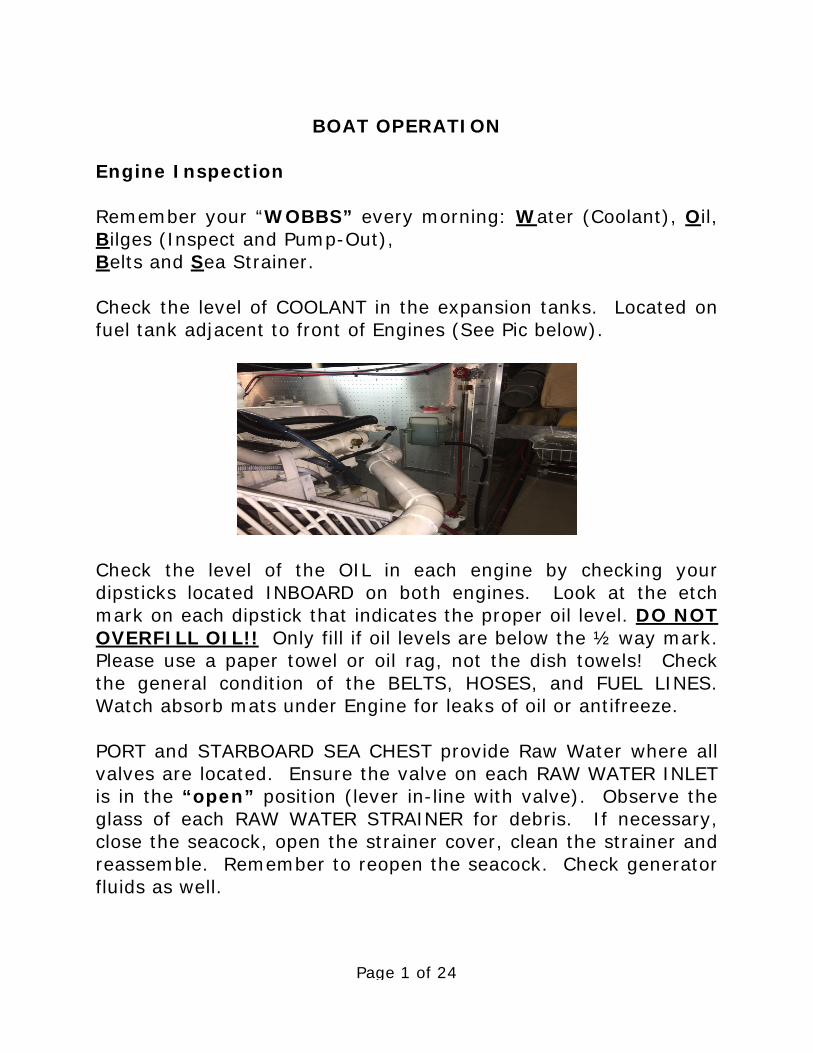
BOAT OPERATION Engine Inspection Remember your “WOBBS” every morning: Water (Coolant), Oil, Bilges (Inspect and Pump-Out), Belts and Sea Strainer. Check the level of COOLANT in the expansion tanks. Located on fuel tank adjacent to front of Engines (See Pic below).
Check the level of the OIL in each engine by checking your dipsticks located INBOARD on both engines. Look at the etch mark on each dipstick that indicates the proper oil level. DO NOT OVERFILL OIL!! Only fill if oil levels are below the ½ way mark. Please use a paper towel or oil rag, not the dish towels! Check the general condition of the BELTS, HOSES, and FUEL LINES. Watch absorb mats under Engine for leaks of oil or antifreeze. PORT and STARBOARD SEA CHEST provide Raw Water where all valves are located. Ensure the valve on each RAW WATER INLET is in the “open” position (lever in-line with valve). Observe the glass of each RAW WATER STRAINER for debris. If necessary, close the seacock, open the strainer cover, clean the strainer and reassemble. Remember to reopen the seacock. Check generator fluids as well.

Page 2 of 24
Start-up Before starting the engines, do your inspection. The engines should be started from the lower helm station. Ensure GEARSHIFTS are in “neutral”, or the engines cannot be started because of the “neutral lockout”. Insert both keys into the IGNITION SWITCHES. Normally, plan to start the STARBOARD engine first, as it has main hydraulic pump. Be sure to check engine(s) exhaust to assure raw water is expelled while engine(s) are running. First, turn on engine(s) Red Covered Control Power Switch, located next to Pilot House Engine Controls (See Pic below)
then turn the key clockwise partially until the ENGINE ALARM sounds and pre-heat the engines. Red and Yellow warning lights will be on momentarily. When lights go out Push Start Button to engage the engine. REPEAT for PORT ENGINE. If the starter does not engage when the start button is pushed, move the gearshift lever slightly until you find neutral and try again. If the engine cranks slowly or fails to turn over, check the condition of the battery on the DC ELECTRICAL PANEL. If battery is low, try the BATTERY PARALLEL SWITCH located PORT SIDE OF LAZARETTE BULKHEAD to connect the other engine battery. Turn off after using.

Page 3 of 24
Warm the engine for about 5 minutes before engaging the transmission. Observe the readings of the gauges. The oil pressure will register about 45-50 PSI. The engine temperature should rise slowly. Turn on engine room in/out blowers in DC Panel. Note—If oil pressure is low, shut down engine and inspect engine compartment and look for possible cause (for example, loss of oil). Caution—If an engine is overheating or there is lack of raw water expelled in the engine exhaust, stop the engine immediately. Recheck the raw water-cooling system to ensure the seacock is “open” (handle in-line with valve). Next, check the raw water strainer for debris. Remove the strainer, clean, re-assemble, and reopen the raw water intake valve (seacock). Restart the engine and recheck water flow from the exhaust. If water is not flowing properly, the RAW WATER PUMP may need to be serviced. Seek help. Shut-Down Before shutting down, allow the engines and turbo’s to “idle” for about 5 minutes to cool them gradually and uniformly. The time engaged in preparing to dock the boat is usually sufficient. Ensure each “ENGINE CONTROL” is in the “neutral” position. Turn the engines off by turning keys to off position and switch off engine control power. Getting Underway DISCONNECT the shore power cord (see 120/240 AC Volt). Close the PORTHOLES, WINDOWS and FORWARD HATCH. Turn on your VHF, electronics and Stern and Bow Thrusters. (See Bow and Stern Thrusters section of this manual). Make sure all pushbuttons on all cabinets and drawers in Galley and Salon are in the closed position. Check all doors are locked into their latches. Shower and medicine cabinet doors should be shut and in the locked position. Assign crew members their various positions. Once outside the Marina, idle the engines while crew brings in fenders and lines.

Page 4 of 24
Cruising All close quarters maneuvering should always take place from the BRIDGE HELM. Engage the ENGINE CONTROL. Ensure the throttles are in the “neutral” position before engaging the gearshifts to avoid transmission damage. Cruising speed is a maximum of 1850 RPMS FOR A SHORT TIME (10 to 15 minutes). If you run at 1700 rpm’s you will cruise at 8.0+ knots and use >10 gallons of diesel per hour. Your speed will vary depending upon the weight, load, weather and sea conditions. NOTE—Avoid higher engine speeds as it causes HIGHER ENGINE TEMPERATURE* possible damage, and higher fuel consumption. *Water Heater is also heated by the engine coolant which is normally 180°-183°. Increased engine RPMS will result in temperatures in water heater tank to exceed the tank temperature safety valve setting of 185° and discharge hot water into bilge and can eventually deplete fresh water tanks. *SEE SAFETY WARNING IN HOT WATER TANK WARNING PG. 16. Docking (Prefer Starboard Tie/Stern In) Have your crew ready dock lines and fenders and give clear instructions on how you will be docking. Often times your crew will need to step off with the stern line. During positioning the boat for docking, use the FLYBRIDGE HELM STATION for greater visibility to the stern. Once you begin backing into slip take the engine and thruster controls at AFT HELM STATION. We prefer to use the AFT starboard gate to access the dock. Another crew member will need to be at the bow or mid-ship to hand over the next line.

Page 5 of 24
While moving slowly to the dock or mooring location, center the WHEEL (e.g. rudders straight) and use only the GEARSHIFTS, THROTTLES and THRUSTERS to maneuver the boat. AFT BOW AND STERN THRUSTERS are hydraulically operated by two sources, starboard engine and 32kw generator auxiliary hydraulics. AFT BOW THRUSTER and WINDLASS CONTROL PANEL is located in engine room AFT wall, Starboard side (See Pic below).
The power supply breaker to ABT CONTROL PANEL (must be on/up) and is located on ABT CONTROL BOX on side nearest Lazarette hatch. Next turn on Bow Thruster breaker in DC panel. The system is now ready for operation of THRUSTERS or WINDLASS. Select square green push button marked MAIN PUMP OR GEN PUMP or push both for WINDLASS operation or FULL THRUSTERS POWER. KNOT TO WORRY has variable speed thrusters. These allow use of small to large increment of power and also the ability to “pin” the boat gently to a dock while securing mooring lines.

Page 6 of 24
Fueling up OPEN FILLER CAP(S) located inside single door (located mid ship walkways) both Port and Starboard sides next to forward gates (See PIC below).
MAKE SURE YOU HAVE THE RIGHT FUEL!!!! DIESEL, DIESEL, DIESEL. MAKE SURE IT IS GOING INTO THE RIGHT DECK FILL. DOUBLE-CHECK! Before pumping, have oil/fuel sorbs handy to soak up spilled fuel. You should have a rough idea of the number of gallons you will need by the engine hour indicator. Periodically have someone monitor fuel sight gauges on tanks. Turn off all engines and generators. Each tank has individual fill nozzles that fill the FORWARD and AFT tanks respectfully each side. “Prefer” to isolate each tank by closing tank outlet valves @ each tank and then opening sight glass valves to allow visual as each tank is filled. “AFTER” FILLING ALL FOUR TANKS be sure to open all outlet valves and close sight glass valves. “FAILURE TO OPEN OUTLET VALVES WILL CAUSE FUEL STARVATION TO DIESEL ENGINES”!! Place the DIESEL nozzle into the tank opening, pump slowly and evenly, and note the sound of the fuel flow. Pumping to fast may not allow enough time for air to escape, which may result in spouting from the tank opening. As the tank fills, the sound will
Page 7 of 24
rise in pitch or gurgle. Pay attention to the TANK OVERFLOW VENT on the outside of the hull near the tank opening. The sound may indicate that the tank is nearly full. Top off carefully, and be prepared to catch spilled fuel. Spillage may result in a nasty fine from law enforcement. Replace each tank cap. Turn on blowers before starting engine. Caution----Clean up splatter and spillage immediately for environmental and health reasons. Wash hands with soap and water thoroughly. CONFIRM ALL FUEL SUPPLY LINE VALVES ARE RETURNED TO OPEN POSITION!!!!
BOAT ELECTRICAL The electrical system is divided into two distribution systems: 120/240 volt AC and 12-volt DC. The systems are controlled from the AC ELECTRICAL PANEL and DC ELECTRICAL PANEL which are located in PILOT HOUSE. The SHORE PANEL GENERATOR/OFF SELECTOR SWITCHES are found in A/C ELECTRICAL PANEL. Additionally, there are another set of BREAKERS*, GENERATOR, START/STOP STATIONS and PNEUMATIC COMPRESSOR BREAKER located on AFT wall/Port side of engine room inside WHITE BOX with finger latch to open door. When not connected to shore power or running a generator, batteries are providing all power. Therefore, monitor the use of the onboard electricity carefully with the Magnum Remote Control/Monitor located in DC PANEL, and turn off electrical devices that are not needed.

Page 8 of 24
120/240 Volt AC System 50 AMP SHORE POWER supports all AC voltage equipment and receptacles on board, as well as the battery charger(s). There are FOUR SHORE POWER INLETS for 50 amps AC power. These are located at both bow and stern and marked Shore 1 or Shore 2 at each location. Additionally, a selector switch is utilized to switch between Forward or AFT feeds. This switch is located (SEE PIC below) on WHITE MAIN BREAKER BOX located on AFT/PORT SIDE wall of Engine Room. Make sure to switch to Forward at selector.
BOW DECK RECEPTACLE- To connect to shore power from BOW DECK (50 amp cord is located under BOW DECK settee), plug the 50 amp POWER CORD into the FORE DECK boat receptacle then into the dock receptacle. AFT DECK RECEPTACLE- To connect to shore power from the AFT DECK (50 amp cord is located in Cable Master Storage Unit on PORT side of swim deck) make sure CABLE MASTER BREAKER in DC PANEL is in on position. Unscrew cap on cable storage unit. TOGGLE SWITCH will power cable in or out. MAKE SURE TO RETURN TOGGLE SWITCH BACK TO OFF POSITION TO PREVENT CONTINUED RUNNING IN OR OUT. MAKE SURE CABLE MASTER BREAKER in DC PANEL IS IN OFF POSITION.
Page 9 of 24
Check the power rating/plug size of the nearest dock receptacle (that is 50 amp, 30 amp, 20 amp and 15 amp). If necessary, use 30 amp CORD ADAPTER located in forward settee. Turn the dock power on. Cords coming off the bow can be wrapped loosely around the bow line. “BEWARE THAT USING ANYTHING LESS THAN 50 AMP SHORE POWER WILL REQUIRE POWER MANAGEMENT TO PREVENT THE BLOWING OF BREAKERS ON DOCK. At the AC ELECTRICAL PANEL, flip the SHORE SELECTOR SWITCHS TO EITHER SHORE 1 OR SHORE 2. Then turn on appropriate breakers for Battery Charger, House #1, Battery Charger Electronics, and Inverter Charger, Refrigeration, Water Heater Range/Oven, Microwave, etc. Watch your amp meters for load. If the load exceeds amperage rating, you will pop your incoming line breaker. *If this occurs, wait to turn on one of your systems (i.e. Water Heater) until your use of amperage drops. If your outlets fail to work, check your GFI’s to make sure that they have not been tripped. *Incoming Shore Power Breakers (Shore Power 1 & Shore Power 2) are located inside WHITE BOX located at AFT wall of Port Side Engine Room. Refer to picture on previous page. Inverter Power The INVERTER provides AC power to the 110-volt receptacle plugs (i.e. microwave oven) when the boat is disconnected from shore power. The inverter does not provide power to the water heater or the battery charger and several other items in Group 1 & Group 2 240 VAC systems. Your remote inverter control panel is located in DC Panel with an on/off switch in the AC Panel. Make certain that it is on. The Magnum inverter is located in the Lazarette Starboard side above batteries.

Page 10 of 24
The inverter’s power source is the DC House Batteries located in Lazarette. The quality on DC power is limited to the capacity of these batteries. Therefore, running hair dryers, toaster, coffeepots, space heaters, etc. will quickly discharge the house/inverter batteries. Use these items VERY SPARINGLY. Refrigerator/Freezer and Ice Maker can be on during overnight Inverter Operation. When connected to shore power, the inverter automatically becomes a battery charger for the 12-volt HOUSE BATTERIES. Should you detect the inverter failing to charge the house batteries, check the circuit breaker in the AC Panel. And the inverter control panel in DC Panel. Generator 12 KW GENERATOR - To start the 12 KW GENERATOR, first check that your generators fluids are topped off and the raw water intake is open. The generator controls are located in both AC Panel and White Box Aft wall of Engine Room. First pre-heat the 12 KW generator for about 20 seconds. Then while still pre-heating, turn the switch to start. Hold the switches in that position while generator catches (about 5-10 seconds). 32 KW GENERATOR - To start the 32 KW GENERATOR, first check that your generators fluids are topped off and the raw water intake is open. The generator controls are located in both AC Panel and White Box Aft wall of Engine Room. First pre-heat the 32 KW generator for about 20 seconds, then “RELEASE PREHEAT” and then hold start switch until 32 KW is running. Make sure water and exhaust is exiting the Stern Discharge.

Page 11 of 24
After generator(s) are running, turn AC Selector Switches to either: GEN 1 - 12 KW GEN 2 - 32 KW Then turn on AC system as you would on shore power one system at a time. To turn the generator off, first take off the load by turning off AC Breakers. Then turn off main AC Selector Switches. Lastly kill the generator by switching generator switch to “OFF” until it dies. Six battery banks support 12-volt DC power: 1) port engine battery 2) starboard engine battery 3) house battery bank (consists of 4 ea. 6V-L16 AGM). 4) Inverter bank (consists of 4 ea. 6V-L16 AGM) 5) Generator batteries for 12KW & 32 KW. The BATTERY SWITCHES are located on LAZARETTE WALL above batteries. Normally, leave the ENGINE/GENERATOR and HOUSE SWITCHES in the “ON” position. Note—Do not change the position of the switches while the engines are running or the alternator diodes will be damaged. Change positions with the engines turned off. Your 12 volt panel should show all the systems supported by your batteries. Primarily you will be turning on the breakers for your lights, water pressure, electronics, etc. Bilge pumps are always on. Your breakers such as Electronics, TV/Satellite, Microwave, Disposal, Washer, Central Vac, should always be turned off before going to bed each night. House Battery Bank & Switch The HOUSE BATTERY BANK provides power for all DC systems, except the engines, generators and 3 automatic bilge pumps. When disconnected from shore power, all 12 volt devices drain

Page 12 of 24
the house battery. Use devices as needed. The DC voltmeter on the DC panel can be switched between House 1, house 2, and both battery banks to measure charging or resting battery voltages. When a battery bank is being charged, the voltage will read from about 13.1 volts to 14.4 volts depending upon state-of-charge of the battery bank. When the battery bank is at rest, (that is, not being charged), the Magnum Control Panel provides state-of charge of the battery bank. Engine batteries are charged by the engine ALTERNATORS while underway. Additionally, the Port Engine has an extra Alternator that charges House Batteries while under way. The Engine/House batteries are charged by the BATTERY CHARGER when connected to shore power. Ensure the Battery Chargers and Inverter circuit breakers at the electrical panel are “ON”. The GENERATOR will also charge the batteries.
Voltage (AGM Batteries) Battery State
12.65 volts 100%
12.47 volts 75%
12.25 volts 50%
11.95 volts 25%
11.70 volts 0% Battery Parallel Switch Each ENGINE BATTERY is connected to its corresponding engine. However, should one engine battery be insufficiently charged to start its engine, the other engine battery may be momentarily connected to provide a boost. Switch the BATTERY PARALLEL SWITCH located in LAZARETTE above Port Engine battery. After Engine has started.

Page 13 of 24
SANITATION SYSTEM
Marine Toilet It is important that each member of the crew be informed on the proper use of the MARINE TOILET. The valves, openings, and pumps are small and may clog easily. If the toilet clogs, it is YOUR RESPONSIBILITY!! ONLY WHAT YOU HAVE HAD TO EAT OR DRINK SHOULD GO INTO THE HEAD AND A MODEST AMOUNT OF MARINE TOILET PAPER.
GENTLEMEN WE PREFER THAT SIT DOWN RULES APPLY. UNLESS YOU ARE CLEANING TOILET, WALLS and FLOOR AROUND TOILET AFTER EACH USE. Always pump the head for children, so you can make sure nothing foreign is being flushed. Caution–Never put paper towels, tampons, Kleenex, sanitary napkins, household toilet paper, or food into the marine toilet. Use only special dissolving marine toilet tissue by AYC. To use the toilet, see DIAGRAM:

Page 14 of 24
Flush sufficiently to move effluent in the hoses; heavy effluent may clog hoses. Clean toilet as necessary. The VACCUFLUSH status panel is located on front of the vanities. There is a switch to turn panel on/off. Green light indicates toilet is ready to flush. Red light indicates “DO NOT FLUSH”! System vacuum pump runs (you can hear it) for several seconds before stopping and Green light comes on again. Caution - should status light remain Red and the pump continues to run after several minutes the seal needs to be cleaned. First switch off on panel. While stepping on lever, use toilet brush located next to toilet and scrub vigorously into the toilet bowl opening to free any debris. Lift foot off lever, turn switch on and wait for red light to switch to Green. If light still remains Red and pump is still engaged, redo cleaning until Red light changes to Green. Normally once is sufficient. Holding Tank The sanitation HOLDING TANK (Black Water) holds approximately 100 gallons. Be aware of the rate of waste production (about 1 gallon per flush). With an overfilled tank, it is possible to break a hose, clog a vent or burst the tank. The result will be indescribable catastrophe and an EXPENSIVE FIX to you. Empty the tank EVERY OTHER DAY to avoid this problem. The HOLDING TANK is located under Bunk and VIP companionway floor hatches. Sometimes it may be subject to a visual check with a flashlight or the “watermelon” test by thumping it. There is a tank watch warning light located in HELM, “but do not rely upon this as they often get clogged.” The HOLDING TANK is emptied in one of two ways: The overboard pump Y valve should always be in position to close off overboard pump and allow pumping out tank. This Y valve should be locked/secured.
Page 15 of 24
#1 At the Marine Pump-Out Station, remove the WASTE CAP located at Starboard walkway deck next to forward gate. Insert the pump-out nozzle into the waste opening. Double check your deck fitting! Turn on pump and open valve located on handle. When pumping is finished, close lever and handle and turn off pump. Remove from deck fitting. If there is a fresh water hose on the dock, rinse the tank by adding water into the tank for 5 minutes. Then re-pump to leave the tank rinsed for the next charter. This also eliminates head odors. #2 The tank’s contents can be discharged with the SEALAND MACERATOR “located ahead of starboard engine” only in Canadian waters and only in open flowing areas - NO BAYS OR MARINA’S. To operate the macerator, switch Y valve next to macerator to open to overboard. Turn on over board breaker in DC electrical panel and then turn black water key switch to on. Listen to macerator’s sound. When the pitch becomes higher, the tank is empty. Discharge may be observed on the Starboard side. It should only take a few minutes to empty tank. Be sure to return Y valve to isolate overboard discharge and secure/lock when re-entering US waters. Y Valve The toilets direct waste effluent into the sanitation-holding tank. The Y-VALVE is located next to macerator pump. A plastic tie wrap keeps the handle pointed to the holding tank-the normal position. Y-valves are usually wire-tied to the holding tank position in respect to Coast Guard regulations. Please leave it “as is” unless there is an emergency. Be familiar with the applicable laws concerning dumping sewage directly overboard.
Page 16 of 24
WATER SYSTEM Fresh Water Tank(s) The FRESH WATER TANK’S hold 400+ gallons. Observe the water level by LEVEL GAGE AT HELM. Waste water from the sinks and showers drain overboard through above water line thru-hulls usually located under the sinks. To refill the tank, remove BOTH WATER CAP(S) located at BOW. Avoid flushing debris from the deck into the tank opening. DO NOT fill water and diesel at the same time! Run enough water thru the garden hose to flush it before adding water to tanks. Fresh Water Pressure Pump(s) Both 120V AC and 12V FRESH WATER PUMPS are located behind water heater. Activate the 12V or 120V AC Pump Breakers as required by 12V Inverter usage or 120V AC generator usage. If the water pump continues to run, you are either out of water or might have an air lock and need to bleed the system by opening up a faucet. If you run out of water SHUT OFF YOUR HOT WATER HEATER on the AC Panel. Serious damage can occur! Hot Water Tank The HOT WATER HEATER has a 40 gallon capacity tank and is available when connected to shore power or via a heat exchanger underway. To use on shore power, flip on the water heater circuit breaker on the AC electrical panel. Do not use the water heater if the water tank level is very low. The water heater is located Port side AFT of 12KW generator.
Page 17 of 24
Shower WARNING DURING PORT ENGINE OPERATION WHILE UNDERWAY AND FOR HOURS AFTER ENGINE IS SHUTDOWN THE WATER TANK TEMP CAN BE ABOVE 180°. Be careful to “EDUCATE” all members on board. Before taking a SHOWER, make sure water pressure and shower sump breakers are on. Take only very short “boat” showers (turning off water between soaping up and rinsing). To keep shower tidy wipe down the shower stall and floor. Check for accumulation of hair in the shower and sink drains. Ensure that the faucets and nozzle are completely off after use. Sump pumps are located near Shower Drains and both Master Head and VIP Head. Master Head access to sump box is the floor hatch at bottom of Master Suite. VIP access to sump box is floor hatch next to VIP entry door. (Toilet Macerator’s are located in the same area)
GALLEY
Stove/Oven The stove and oven are electric. Turn on the “stove” breaker on the AC panel. Any additional information needed on operation of oven, stove and microwave is available in manuals located in Pilot House cabinet. Refrigerator/Freezer/Ice Maker The REFRIGERATOR*/FREEZER and ICE MAKER IN PILOT HOUSE are 120V power. They will automatically use 120V power when the shore power is connected, when a generator is being use or will run off the inverter.

Page 18 of 24
*At this time the ice maker and water dispenser on the refrigerator are out of service. We put ice from the ice maker in Pilot House into the refrigerator ice dispenser to use the cube dispenser. Filtered drinking water is available from the fresh water dispenser on galley sink. Trash Compactor Extra bags for trash compactor are under the galley sink. Don’t compact trash until the bin is at least half way full of debris. Built in Cabin Heat (AC) with Reverse Air Cabin Heat and AC with Reverse Air are available when connected to shore power or 32KW generator is running. Control Panels for each area are located in the Main state room, one in VIP room, and also in the Pilot House, Galley and Salon. Make sure the AC breakers are on at the AC panel. SMX II Controls are located in Pilot House, Master Suite and VIP Suite (bunk house is controlled by VIP Controls). Picture of SMX II Controls
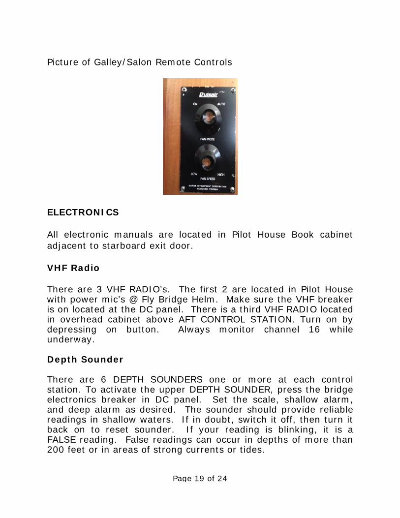
Pilot House SMX II controls Heating and Cooling in Galley and Salon which have remote Cruisair fan, Auto/Manual controls for each area (see PIC Below)
Page 19 of 24
Picture of Galley/Salon Remote Controls
ELECTRONICS All electronic manuals are located in Pilot House Book cabinet adjacent to starboard exit door. VHF Radio There are 3 VHF RADIO’s. The first 2 are located in Pilot House with power mic’s @ Fly Bridge Helm. Make sure the VHF breaker is on located at the DC panel. There is a third VHF RADIO located in overhead cabinet above AFT CONTROL STATION. Turn on by depressing on button. Always monitor channel 16 while underway. Depth Sounder There are 6 DEPTH SOUNDERS one or more at each control station. To activate the upper DEPTH SOUNDER, press the bridge electronics breaker in DC panel. Set the scale, shallow alarm, and deep alarm as desired. The sounder should provide reliable readings in shallow waters. If in doubt, switch it off, then turn it back on to reset sounder. If your reading is blinking, it is a FALSE reading. False readings can occur in depths of more than 200 feet or in areas of strong currents or tides.
Page 20 of 24
Radar To operate the GARMIN RADAR, switch radar breaker on in DC panel, to turn the radar on. To turn off switch breaker off. Remember you are not allowed to travel in FOG, during hours or darkness or in serious wind conditions. Global Positioning System (GPS) Several fixed mounted GPS (GARMIN) are on the FLYBRIDGE ARCH. Ascertain that your GPS breaker is on. It works by turning on all electronics. Refer to the manual found in Pilot House Book cabinet or use Garmin 7616 on screen manuals. ENTERTAINMENT SYSTEMS AM/FM is not available at this time. DVD Player is not available at this time TV/SATELLITE The TV is connected to Dish Satellite and controlled by receiver above TV. Using the Dish remote push SAT and Red power button to turn the receiver on. Then push AUX button and Red power button to turn TV on. Push SAT button to control the channels for viewing. Push AUX to control volume of TV. The TV must be on INPUT 5 to view television. Make sure that Satellite breaker is turned to the on position. Should TV show message “no satellite signal available” unplug the receiver (located behind TV) for 20 seconds then plug it back in. The satellite system will reset and television channels should be available. If the same no satellite message appears redo steps above. If after unplugging the system twice and there are still no channel selections, you do not have access in the area you are in or there is a problem with the satellite. CALL AYC FOR INSTRUCTIONS!!!!

Page 21 of 24
ANCHORING (WITH HYDRAULIC “GALLEY MAID” WINDLASS
The primary WORKING ANCHOR is a 60KG BRUCE and is attached to 300 ft. of chain on each anchor through deck from the ANCHOR LOCKER. The locker can be accessed through the VIP stateroom cabinet at head of bed. The WINDLASS POWER SWITCH is located next to hydraulic pump switch’s in the Pilot House. To lower the anchor, turn brake wheel counter clock wise until you can feed about 18" inches of chain out and then re-tighten brake wheel. Tighten brake band by turning brake wheel counter clock wise. Now guide the anchor over the anchor roller to prevent binding on the pulpit. Use brake wheel to slow anchor deployment and let out sufficient ANCHOR RODE before setting anchor. Colored markers are placed every 50 feet on the chain indicating amount of rode. If the anchorage is crowded put down at least a 3 to 1 scope (60 feet to 20 feet of water), back the anchor in with a short burst from the engine. Then let out additional scope dependent upon conditions. 5 to 1 is a good rule of thumb in moderate conditions (up to 15 knots) 7 to 1 in conditions above 15 knots. Be attentive to the changes in depth due to tidal fluctuations and its impact on scope. Before restarting windlass and raising the anchor, ALWAYS start engines and 32 KW generator, as Windlass uses large amounts of Hydraulic power. Tighten clutches first and then loosen brake bands. Turn on the WINDLASS SWITCH and as the boat moves toward the anchor, press the “up” foot control to take up slack line. Have one person “follow” the chain by putting the boat in and out of gear so that the Windlass does not pull the boat to the anchor. Place yourself in position to guide the anchor onto the roller. As the anchor rises, be careful not to allow it to swing against the hull. Wash down chain and anchor as it is retrieved before it goes into chain locker.

Page 22 of 24
Reconnect the keeper between the anchor and Windlass Base. Close the plastic covers on the FOOT PEDAL CONTROL SWITCHES. A spare 30KG anchor is stowed adjacent to main anchor. The 300 ft. spare anchor rode is located in Starboard locker and is attached to the rode.
BARBECUE
The barbecue and mounting bracket are stored on the starboard rail next to Dinghy. Attach a PROPANE BOTTLE to the regulator found in FLYBRIDGE LOCKER. Carefully light the unit. The barbecue generates a lot of heat and cooks hot and fast. Please wipe with a paper towel before covering to prevent grease and dirt soiling the cover. Note: EXTRA Propane bottles are not stocked by AYC. You will need to purchase several extras are not found on board. For safety reasons, do not store an opened propane bottle in the salon or engine compartment. Chances are these will leak slightly once opened and propane gas could settle into low spaces. Ensure gasoline and flammable materials are not near the barbecue.
DINGHY AND OUTBOARD MOTOR Your NOVURANIA DINGHY with a 50hp HONDA engine is stored on Fly Bridge Deck above Salon Davit. Davit has a capacity of about 1,500 lbs. (motor and equipment). Davit has control breaker in AC Panel and breaker in Lazarette on Port Side above batteries. Launching and retrieving is a two person job. DO NOT RAISE HOIST BLOCK INTO DAVIT ARM!!!
Page 23 of 24
To deploy the dinghy, clip the 3 way bridle to the three lift points inside dinghy and attach bridle lift ring to davit hook. REMOVE 3 CRADLE TIE DOWNS PRIOR TO HOISTING. Be sure to place tag lines to Dinghy bow/stern and to davit arm. This is necessary to control the swing of davit arm as dinghy is hoisted and deployed out back of boat deck, over cockpit and around to port side where it can be lowered into water. Holding the dinghy and the tag lines lower the dinghy into the water. When removing dinghy from salt water, (motor is to be fully tilted up) you must flush engine with fresh water while dinghy is in cradle with tie downs attached and motor is lowered just above resting pad. DO NOT TOW DINGHY!!!!! Coast Guard regulations state that any child, under 14, must wear a life jacket in a dinghy. It is a good idea for everyone to follow this rule. CRABBING AND FISHING Always check the fishing and crabbing requirements before you leave on your cruise. You will need a license. Some areas are CLOSED to crabbing and fishing on certain months. Fish-flavored cat food with the pop-up ringed lids work the best for a nice neat way to bait the trap. After 15-20 minutes, retrieve the crab line and trap quickly. Measure the crabs using the CRAB MEASURING GAUGE normally located in Pilot House. Keep the male crabs of proper size (usually 6 1/4 inches across the carapace). Boil crabs about 12 minutes to cook. After using, wash equipment thoroughly with fresh water (available from the cockpit shower faucet). Note— Please do not store wet pots or gear inside the boat or Lazarette.

Page 24 of 24
OTHER: SAFETY & BILGE PUMPS SAFETY should be paramount in your daily cruising. A MAN OVER BOARD DRILL should be discussed and perhaps even practiced with a life jacket. Remember your life jackets are stowed in FLY BRIDGE LOCKER. A few should always be out and ready. Your flares and safety equipment are located in FLY BRIDGE locker. 3 Bilge areas are equipped with an AUTOMATIC BILGE PUMP. The master switch is located overhead above main helm. Normally, the switch will be left in the AUTO position. You may occasionally hear the pump operate due to condensation and water from the shaft log accumulating in the bilge. An AUXILIARY HAND OPERATED BILGE PUMP is operated from mid ship in the engine room using the handle provided for that purpose (forward engine room). This is used only in emergency situations. The ENGINE SPARE PARTS are stowed in parts locker. This includes oil filter, raw water impeller, pump parts, injectors, and other small parts.
THRU HULL LOCATIONS 2-Sea Chest AFT OF BOTH ENGINES 1-THRU HULL FOR WATER MAKER BELOW FLOOR PLATE IN LAZARETTE (FORWARD OF WATER MAKER). 1-THRU HULL STARBOARD SIDE OUTSIDE AIR COMPRESSOR FOR DEPTH SOUNDER 4-THRU HULLS FOR STABILIZERS (2 LOCATED OUTBOARD FRONT OF BOTH ENGINES AND 2 LOCATED OUTBOARD NEAR AFT ENGINE ROOM WALL.


