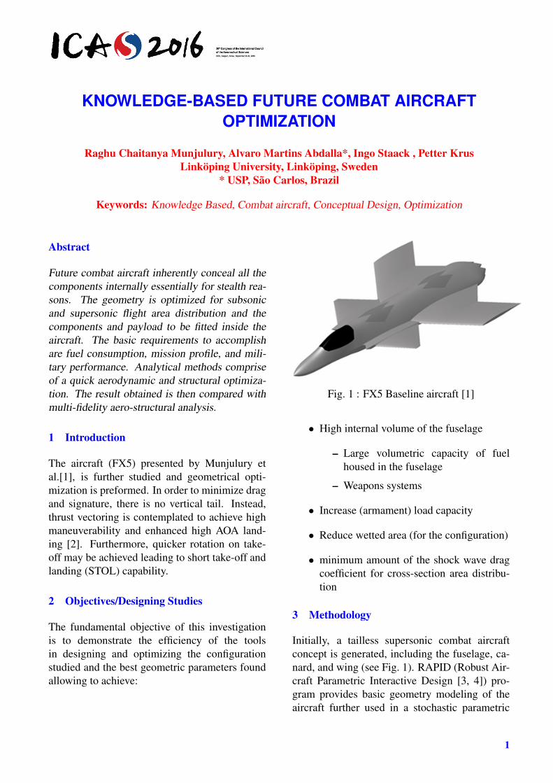
KNOWLEDGE-BASED FUTURE COMBAT AIRCRAFT OPTIMIZATION Raghu Chaitanya Munjulury, Alvaro Martins Abdalla*, Ingo Staack , Petter Krus Linköping University, Linköping, Sweden * USP, São Carlos, Brazil Keywords: Knowledge Based, Combat aircraft, Conceptual Design, Optimization Abstract Future combat aircraft inherently conceal all the components internally essentially for stealth rea- sons. The geometry is optimized for subsonic and supersonic flight area distribution and the components and payload to be fitted inside the aircraft. The basic requirements to accomplish are fuel consumption, mission profile, and mili- tary performance. Analytical methods comprise of a quick aerodynamic and structural optimiza- tion. The result obtained is then compared with multi-fidelity aero-structural analysis. 1 Introduction The aircraft (FX5) presented by Munjulury et al.[1], is further studied and geometrical opti- mization is preformed. In order to minimize drag and signature, there is no vertical tail. Instead, thrust vectoring is contemplated to achieve high maneuverability and enhanced high AOA land- ing [2]. Furthermore, quicker rotation on take- off may be achieved leading to short take-off and landing (STOL) capability. 2 Objectives/Designing Studies The fundamental objective of this investigation is to demonstrate the efficiency of the tools in designing and optimizing the configuration studied and the best geometric parameters found allowing to achieve: Fig. 1 : FX5 Baseline aircraft [1] • High internal volume of the fuselage – Large volumetric capacity of fuel housed in the fuselage – Weapons systems • Increase (armament) load capacity • Reduce wetted area (for the configuration) • minimum amount of the shock wave drag coefficient for cross-section area distribu- tion 3 Methodology Initially, a tailless supersonic combat aircraft concept is generated, including the fuselage, ca- nard, and wing (see Fig. 1). RAPID (Robust Air- craft Parametric Interactive Design [3, 4]) pro- gram provides basic geometry modeling of the aircraft further used in a stochastic parametric 1
Future combat aircraft inherently conceal all thecomponents internally essentially for stealth rea-sons. The geometry is optimized for subsonicand supersonic flight area distribution and thecomponents and payload to be fitted inside theaircraft. The basic requirements to accomplishare fuel consumption, mission profile, and mili-tary performance. Analytical methods compriseof a quick aerodynamic and structural optimiza-tion. The result obtained is then compared withmulti-fidelity aero-structural analysis.
1 Introduction
The aircraft (FX5) presented by Munjulury etal.[1], is further studied and geometrical opti-mization is preformed. In order to minimize dragand signature, there is no vertical tail. Instead,thrust vectoring is contemplated to achieve highmaneuverability and enhanced high AOA land-ing [2]. Furthermore, quicker rotation on take-off may be achieved leading to short take-off andlanding (STOL) capability.
2 Objectives/Designing Studies
The fundamental objective of this investigationis to demonstrate the efficiency of the toolsin designing and optimizing the configurationstudied and the best geometric parameters foundallowing to achieve:
Fig. 1 : FX5 Baseline aircraft [1]
• High internal volume of the fuselage
– Large volumetric capacity of fuelhoused in the fuselage
– Weapons systems
• Increase (armament) load capacity
• Reduce wetted area (for the configuration)
• minimum amount of the shock wave dragcoefficient for cross-section area distribu-tion
3 Methodology
Initially, a tailless supersonic combat aircraftconcept is generated, including the fuselage, ca-nard, and wing (see Fig. 1). RAPID (Robust Air-craft Parametric Interactive Design [3, 4]) pro-gram provides basic geometry modeling of theaircraft further used in a stochastic parametric
1
MUNJULURY, ABDALLA, STAACK, KRUS
Fig. 2 : Framework for Optimization
method based on a database in SOM -Sonic Op-timization Module.
The model is analyzed and evaluated by theaerodynamic and optimization module (SOM)and the new settings are determined to find thegeometric parameters of the configuration satis-fying the design requirements. Analytical andsemi-empirical methods comprise of subsonic,transonic and supersonic aerodynamic drag com-putation.
SOM code, written in Visual Basic language,uses analytical and semi-empirical methods [5,6, 7, 8] in solving the aerodynamic drag prob-lem. Validation performed using open resultsfrom missile shapes and the F16 are presented byCruvinel [9].
4 Optimization Framework
The optimization is performed by using differ-ent tools developed in the conceptual aircraftdesign framework [4] at the Linköping Univer-sity within a national aviation research project(NFFP) started in 2009 [10]. Systems simula-tions and multi-fidelity aero-structural analysisare further utilized in the optimization.
4.1 Geometry
The FX5 aircraft geometry designed and devel-oped in RAPID [3] and the preliminary work
Fig. 3 : Initial effective area distribution for FX5in RAPID, Mach numbers ranging from 1 to 1.4;1.6 to 2; 2.1 to 2.3 and 2.5 [1]
of/on geometry presented in [4] is used in the op-timization. The geometry consists of three mainparts; fuselage, wing, and canard. Wing and ca-nard geometries remain unchanged, only fuse-lage is optimized alongside canard and wing po-sitioning.
The fuselage consists of ten cross-sections.Each of these is optimized for wave drag reduc-tion of the whole aircraft. The cross-sectionscomprise of two Bezier cubic equations as rep-resented in a matrix format in Eq. 1 [11]. As pre-sented in [3] (Fig.6), point 1, point 4 and point 7are dependent on the fuselage splines; Only point2, point 3 point 5, point 6 values are required forthe cross-section geometry modification, in bothBezier cubic equations (Eq. 1) points P2 and P3are modified.
(1)B(t) = U(t)A
where:
U(t) =[t3 t2 t 1
]
A =
−1 3 −3 13 −6 3 0−3 3 0 01 0 0 0
P0P1P2P3
P0P1P2P3
=
P0x P0yP1x P1yP2x P2yP3x P3y
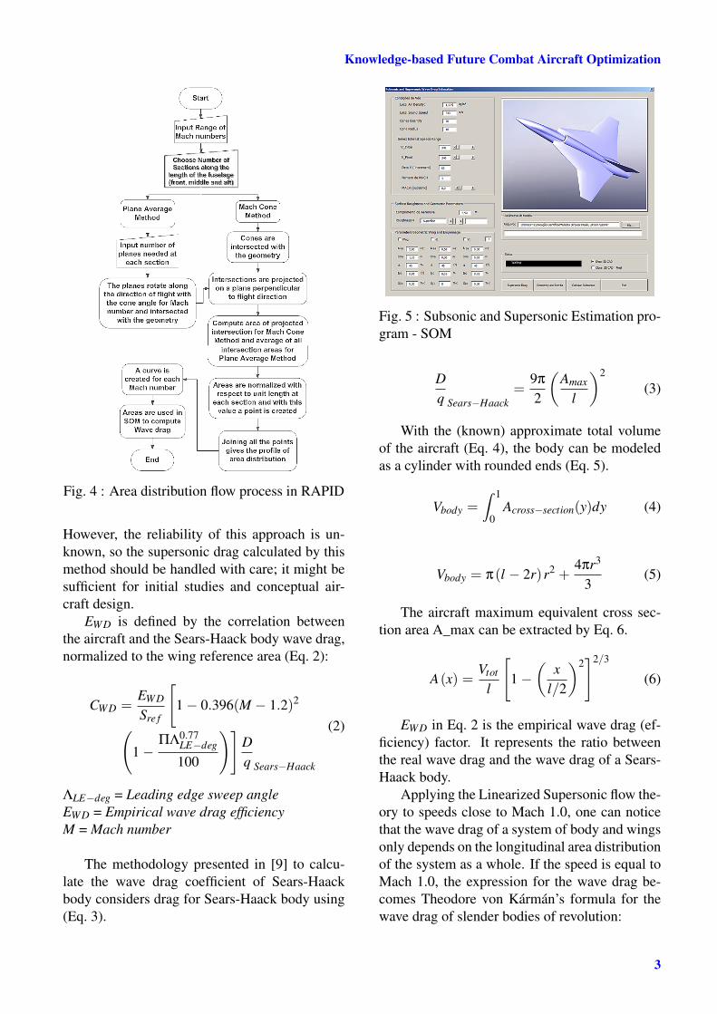
4.2 Sonic Optimization Module (SOM)
For initial wave drag estimation, Raymer method[12] is adopted. Unlike other empirical methods,the Raymer approach takes the geometry and di-mensions of the wing and fuselage into account.
However, the reliability of this approach is un-known, so the supersonic drag calculated by thismethod should be handled with care; it might besufficient for initial studies and conceptual air-craft design.
EWD is defined by the correlation betweenthe aircraft and the Sears-Haack body wave drag,normalized to the wing reference area (Eq. 2):
(2)CWD =
EWD
Sre f
[1− 0.396(M − 1.2)2
(1−
ΠΛ0.77LE−deg
100
)]Dq Sears−Haack
ΛLE−deg = Leading edge sweep angleEWD = Empirical wave drag efficiencyM = Mach number
The methodology presented in [9] to calcu-late the wave drag coefficient of Sears-Haackbody considers drag for Sears-Haack body using(Eq. 3).
Fig. 5 : Subsonic and Supersonic Estimation pro-gram - SOM
(3)Dq Sears−Haack
=9π
2
(Amax
l
)2
With the (known) approximate total volumeof the aircraft (Eq. 4), the body can be modeledas a cylinder with rounded ends (Eq. 5).
(4)Vbody =∫ 1
0Across−section(y)dy
(5)Vbody = π(l − 2r)r2 +4πr3
3
The aircraft maximum equivalent cross sec-tion area A_max can be extracted by Eq. 6.
(6)A(x) =Vtot
l
[1−
(x
l/2
)2]2/3
EWD in Eq. 2 is the empirical wave drag (ef-ficiency) factor. It represents the ratio betweenthe real wave drag and the wave drag of a Sears-Haack body.
Applying the Linearized Supersonic flow the-ory to speeds close to Mach 1.0, one can noticethat the wave drag of a system of body and wingsonly depends on the longitudinal area distributionof the system as a whole. If the speed is equal toMach 1.0, the expression for the wave drag be-comes Theodore von Kármán’s formula for thewave drag of slender bodies of revolution:
3
MUNJULURY, ABDALLA, STAACK, KRUS
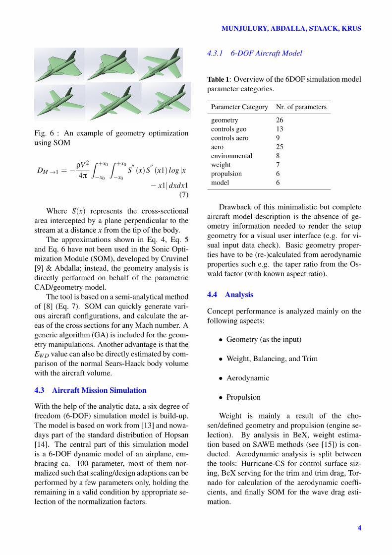
Fig. 6 : An example of geometry optimizationusing SOM
DM →1 = −ρV 2
4π
∫ +x0
−x0
∫ +x0
−x0
S′′(x)S
′′(x1) log |x
− x1|dxdx1(7)
Where S(x) represents the cross-sectionalarea intercepted by a plane perpendicular to thestream at a distance x from the tip of the body.
The approximations shown in Eq. 4, Eq. 5and Eq. 6 have not been used in the Sonic Opti-mization Module (SOM), developed by Cruvinel[9] & Abdalla; instead, the geometry analysis isdirectly performed on behalf of the parametricCAD/geometry model.
The tool is based on a semi-analytical methodof [8] (Eq. 7). SOM can quickly generate vari-ous aircraft configurations, and calculate the ar-eas of the cross sections for any Mach number. Ageneric algorithm (GA) is included for the geom-etry manipulations. Another advantage is that theEWD value can also be directly estimated by com-parison of the normal Sears-Haack body volumewith the aircraft volume.
4.3 Aircraft Mission Simulation
With the help of the analytic data, a six degree offreedom (6-DOF) simulation model is build-up.The model is based on work from [13] and nowa-days part of the standard distribution of Hopsan[14]. The central part of this simulation modelis a 6-DOF dynamic model of an airplane, em-bracing ca. 100 parameter, most of them nor-malized such that scaling/design adaptions can beperformed by a few parameters only, holding theremaining in a valid condition by appropriate se-lection of the normalization factors.
4.3.1 6-DOF Aircraft Model
Table 1: Overview of the 6DOF simulation modelparameter categories.
Drawback of this minimalistic but completeaircraft model description is the absence of ge-ometry information needed to render the setupgeometry for a visual user interface (e.g. for vi-sual input data check). Basic geometry proper-ties have to be (re-)calculated from aerodynamicproperties such e.g. the taper ratio from the Os-wald factor (with known aspect ratio).
4.4 Analysis
Concept performance is analyzed mainly on thefollowing aspects:
• Geometry (as the input)
• Weight, Balancing, and Trim
• Aerodynamic
• Propulsion
Weight is mainly a result of the cho-sen/defined geometry and propulsion (engine se-lection). By analysis in BeX, weight estima-tion based on SAWE methods (see [15]) is con-ducted. Aerodynamic analysis is split betweenthe tools: Hurricane-CS for control surface siz-ing, BeX serving for the trim and trim drag, Tor-nado for calculation of the aerodynamic coeffi-cients, and finally SOM for the wave drag esti-mation.
BeX is an aircraft sizing, weight estimation, dragprediction, balancing, and cabin layout programbuilt in Excel. The user begins with inputtingthe desired geometry and requirements. Enginetype and number of engines are determined bythe necessary thrust. The weight of the aircraftcalculated according to weight penalty methodalso provides drag estimations.
Fig. 7 : BeX Sizing and Structural weight estima-tion using weight penalty method
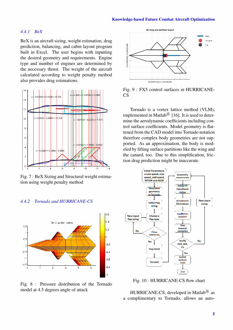
4.4.2 Tornado and HURRICANE-CS
Fig. 8 : Pressure distribution of the Tornadomodel at 4.5 degrees angle of attack
mated sizing of the primary and secondary con-trol surfaces out of a number of known param-eters of an airplane. Initial hypothesis [12, 15,17, 18] size the control surfaces required forthe aircraft. After obtaining the initial param-eters from BeX and geometry from Tornado,HURRICANE-CS performs the following:
• Lift criteria size flaps for take-off and land-ing
• Automatic measures of ailerons, rudder,and elevator based on load cases
• Solves equilibrium and dynamic equationsto obtain time response
• Checks the requirements and iterates theprocess until the conditions fulfillment.
An overview of the control surface sizing processis shown in Fig. 10.
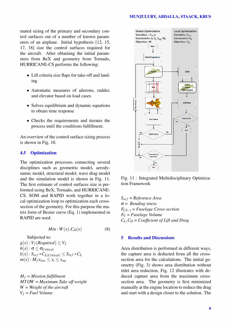
4.5 Optimization
The optimization processes connecting severaldisciplines such as geometric model, aerody-namic model, structural model, wave drag modeland the simulation model is shown in Fig. 11.The first estimate of control surfaces size is per-formed using BeX, Tornado, and HURRICANE-CS. SOM and RAPID work together in a lo-cal optimization loop to optimization each cross-section of the geometry. For this purpose the ma-trix form of Bezier curve (Eq. 1) implemented inRAPID are used.
Min : W (x),CD(x) (8)
Subjected to:g(x) : Vf (Required)≤Vfh(x) : σ≤ σCriticalk(x) : Sre f ∗CL(Critical) ≤ Sre f ∗CLm(x) : M f xlow ≤ xi ≤ xup
M f = Mission fulfillmentMTOW = Maximum Take off weightW = Weight of the aircraftVf = Fuel Volume
Sre f = Reference Areaσ = Bending stressFCS−i = Fuselage Cross-sectionFV = Fuselage VolumeCL,CD = Coefficient of Lift and Drag
5 Results and Discussions
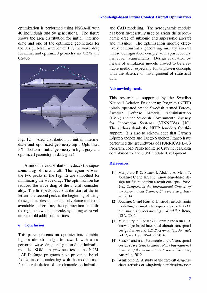
Area distribution is performed in different ways,the capture area is deducted from all the cross-section area for the calculations. The initial ge-ometry (Fig. 3) shows area distribution withoutinlet area reduction, Fig. 12 illustrates with de-duced capture area from the maximum cross-section area. The geometry is first minimizedmanually at the engine location to reduce the dragand start with a design closer to the solution. The
optimization is performed using NSGA-II with40 individuals and 50 generations. The figureshows the area distribution for initial, interme-diate and one of the optimized geometries forthe design Mach number of 1.3; the wave dragfor initial and optimized geometry are 0.272 and0.2406.
Fig. 12 : Area distribution of initial, interme-diate and optimized geometry(top); OptimizedFX5 (bottom - initial geometry in light gray andoptimized geometry in dark gray)
A smooth area distribution reduces the super-sonic drag of the aircraft. The region betweenthe two peaks in the Fig. 12 are smoothed forminimizing the wave drag. The optimization hasreduced the wave drag of the aircraft consider-ably. The first peak occurs at the start of the in-let and the second peak at the beginning of wing,these geometries add up to total volume and is notavoidable. Therefore, the optimization smoothsthe region between the peaks by adding extra vol-ume to hold additional entities.
6 Conclusion
This paper presents an optimization, combin-ing an aircraft design framework with a su-personic wave drag analysis and optimizationmodule, SOM. In previous tests, the SOM-RAPID-Tango programs have proven to be ef-fective in communicating with the module usedfor the calculation of aerodynamic optimization
and CAD modeling. The aerodynamic modulehas been successfully used to assess the aerody-namic drag of subsonic and supersonic aircraftand missiles. The optimization module effec-tively demonstrates generating military aircraftwhose configuration comply with spin recoverymaneuver requirements. Design evaluation bymeans of simulation models proved to be a re-liable method, especially for unproven conceptswith the absence or misalignment of statisticaldata.
Acknowledgments
This research is supported by the SwedishNational Aviation Engineering Program (NFFP)jointly operated by the Swedish Armed Forces,Swedish Defense Material Administration(FMV) and the Swedish Governmental Agencyfor Innovation Systems (VINNOVA) [10].The authors thank the NFFP founders for thissupport. It is also to acknowledge that CarmenLópez Sánchez and Diego Sánchez Franco haveperformed the groundwork of HURRICANE-CSProgram. Joao Paulo Monteiro Cruvinel da Costacontributed for the SOM module development.
References
[1] Munjulury R C, Staack I, Abdalla A, Melin T,Jouannet C and Krus P. Knowledge-based de-sign for future combat aircraft concepts. Proc.29th Congress of the International Council ofthe Aeronautical Science, St. Petersburg, Rus-sia. 2014.
[2] Jouannet C and Krus P. Unsteady aerodynamicmodelling: a simple state-space approach. AIAAAerospace sciences meeting and exhibit. Reno,USA, 2005.
[3] Munjulury R C, Staack I, Berry P and Krus P. Aknowledge-based integrated aircraft conceptualdesign framework. CEAS Aeronautical Journal,vol. 7, no. 1, pp. 95–105, 2016.
[4] Staack I and et al. Parametric aircraft conceptualdesign space. 28th Congress of the InternationalCouncil of the Aeronautical Science. Brisbane,Australia, 2012.
[5] Whitcomb R. A study of the zero-lift drag-risecharacteristics of wing-body combinations near
7
MUNJULURY, ABDALLA, STAACK, KRUS
the speed of sound. National Advisory Commit-tee for Aeronautics, NACATR-1273, 1956.
[6] Ashley H and Landahl M. Aerodynamics ofwings and bodies. 1st ed. Dover PublicationsInc., New York, 1985.
[7] Seebass R. Supersonic aerodynamics: Lift anddrag. Aerospace Engineering Sciences, pp. 1–6,1998.
[8] Jones R T. Theory of wing-body drag at super-sonic speeds. National Advisory Committee forAeronautics, NACATR-1284, 1956.
[9] Cruvinel J P M C. Implementation of a Methodfor Estimating Shock Wave Drag. EESC / USP /Aeronautical Engineering Course -TCC, 2015.
[10] VINNOVA. Swedish national avi-ation engineering research pro-gramme, "[Online; Accessed 27-June-2016]". http://www.vinnova.se/en/Our-acitivities/Cross-borde-co-operation/Cooperation-Programmes/National-Aviation-Engineering-Research-Programme/.
[11] Chang K H. Design Theory and Methods Us-ing CAD/CAE: The Computer Aided Engineer-ing Design Series. Academic Press, 2014.
[12] Raymer D P. Aircraft design: A conceptual ap-proach, american institute of aeronautics and as-tronautics. Inc, Reston, VA, 1999.
[13] Krus P. Whole mission simulation for aircraftsystem design. AST 2009 Workshop on AviationSystem Technology. 2009.
[15] Berry P and Jouannet C. Recycling old weightassessment methods and giving them new life inaircraft conceptual design. 28th Congress of theInternational Council of the Aeronautical Sci-ence. Brisbane, Australia, 2012.
[16] Melin T. A vortex lattice matlab implementationfor linear aerodynamic wing applications. Mas-ter’s Thesis, Department of Aeronautics, RoyalInstitute of Technology (KTH), Stockholm, Swe-den, 2000.
[17] Sadraey M H. Aircraft Design: A Systems Engi-neering Approach. John Wiley & Sons, Chich-ester, West Sussex, 2012.
[18] Roskam J. Airplane design, vol. 2. RoskamAviation and Engineering Corporation, 1985.
The authors confirm that they, and/or their company or or-ganization, hold copyright on all of the original materialincluded in this paper. The authors also confirm that theyhave obtained permission, from the copyright holder of anythird party material included in this paper, to publish it aspart of their paper. The authors confirm that they give per-mission, or have obtained permission from the copyrightholder of this paper, for the publication and distribution ofthis paper as part of the ICAS proceedings or as individualoff-prints from the proceedings.