1 Knurling Rolling of knurlings, or just knurling is defined in DIN 82. Here knurling is divided depending on orientation of axis of knurling in reference to workpiece axis. (Fig .1). Basics Fig 1: Knurlings acc. to DIN 82 What do medical instruments and electric motors have in common? Both objects have rolled knurlings but for completely different purposes. On the one hand the friction between medical instrument and physician glove has to be improved, on the other hand a rotor package has to be assembled on the rotor shaft. T U 30° V 30° T U V RAA, Straight knurling RBL, left handed knurling RBR, right handed knurling RGE Left-Right Knurling, high tips RGV Left-Right Knurling, low tips RKE Cross (diamond) knurling, high tips RKV Cross (diamond) knurling, low tips Tab 1: Additional knurlings acc. to DIN 82 In contrast to rolling of splines with involute profiles or serrations, main geometric dimension of knurlings is the major diameter. Depending on each application this major diameter can also have very tight tolerances. The diameter is resulting from no. of teeth multiplied by pitch. Preferentially the pitch is choosen out of a geometric series of t=0,5; 0,6; 0,8; 1; 1,2; 1,6. Da Major diameter t Pitch z No. of teeth Knurlings are used to implement an economical friction- and shape-locked connection between shaft and hub. A hub made with a circular bore is pressed onto a part (shaft) with a knurling Function Knurling PROFIROLL TECHNOLOGIES REPORTS D= a t*z ∏
Transcript
2 1
Knurling
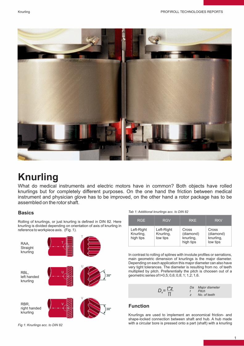
Rolling of knurlings, or just knurling is defined in DIN 82. Here knurling is divided depending on orientation of axis of knurling in reference to workpiece axis. (Fig .1).
Basics
Fig 1: Knurlings acc. to DIN 82
What do medical instruments and electric motors have in common? Both objects have rolled knurlings but for completely different purposes. On the one hand the friction between medical instrument and physician glove has to be improved, on the other hand a rotor package has to be assembled on the rotor shaft.
T
U30°
V
30°
T
U
V
RAA,Straightknurling
RBL,left handed knurling
RBR,right handed knurling
RGE
Left-Right Knurling,high tips
RGV
Left-Right Knurling,low tips
RKE
Cross (diamond) knurling,high tips
RKV
Cross (diamond) knurling, low tips
Tab 1: Additional knurlings acc. to DIN 82
In contrast to rolling of splines with involute profiles or serrations, main geometric dimension of knurlings is the major diameter. Depending on each application this major diameter can also have very tight tolerances. The diameter is resulting from no. of teeth multiplied by pitch. Preferentially the pitch is choosen out of a geometric series of t=0,5; 0,6; 0,8; 1; 1,2; 1,6.
Da Major diametert Pitchz No. of teeth
Knurlings are used to implement an economical friction- and shape-locked connection between shaft and hub. A hub made with a circular bore is pressed onto a part (shaft) with a knurling
Function
Knurling PROFIROLL TECHNOLOGIES REPORTS
D =a
t*z∏
2 1
with a small oversize. This connection is non-detachably. Main application are shafts of electric motors or alternators of different sizes und different electric excitations. The rotor assembly with a copper winding and receiving body is assembled with the body of the rotor shaft.
Often the assembly process and therefore the durability of this connection can be controlled by measuring the needed assembly force. This force can only be constantly repeatable in case the moved material and resistance is constant. This can only be achieved if volume of moved material is constant (same no. of teeth) and the major diameter has to be formed with repeatable precision.
A special application are knurled parts in textile industry (Fig. 2). They are used in Ring Spinning machines for drawing and twisting of slivers.
Fig. 2: Textile cylinders
For mass production the recommended process without any doubt is Cold Rolling. For low quantites forming with rolling head on a lathe can be used. Most important for forming of high quality knurls with precise diameters is a very rigid rolling machine with a backlash free drive chain concept. This is how it can be guaran-teed that the already set-up ground rolling dies achieve a high repeatability in pitch without any changes in no of rolled teeth. Additionally the usage of a feed-controlled Rolling Machines is
Rolling Process
h
sda
ts
Rα
Fig. 3: Profile of knurling
z No. of teethh Profile depthS Tooth thicknessda
t PitchR Radiusα Pressure angle
recommended, e.g. by using a NC or modern PLC solution. Due to this solution the operator can work independently from changes like different material batches, hardnesses or inhomo-geneities and can achieve a consistent high quality.
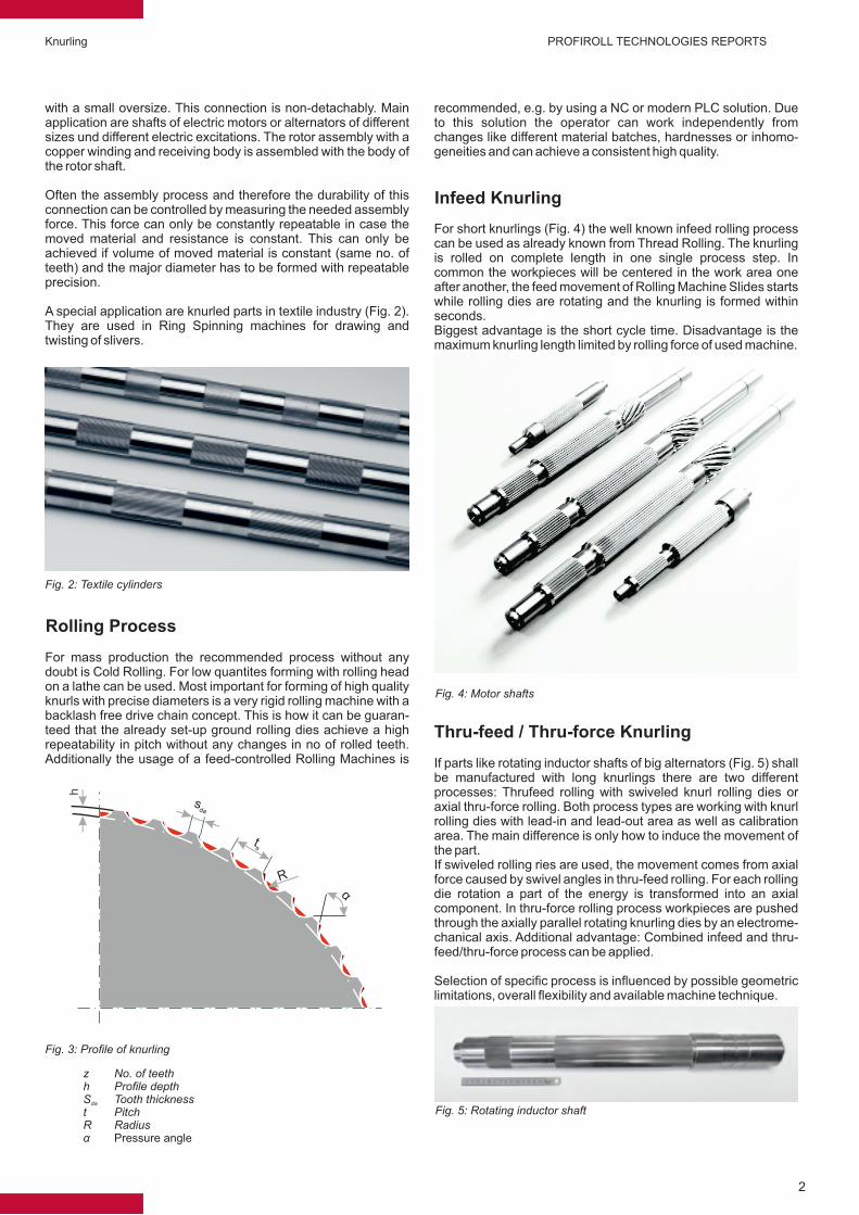
For short knurlings (Fig. 4) the well known infeed rolling process can be used as already known from Thread Rolling. The knurling is rolled on complete length in one single process step. In common the workpieces will be centered in the work area one after another, the feed movement of Rolling Machine Slides starts while rolling dies are rotating and the knurling is formed within seconds.Biggest advantage is the short cycle time. Disadvantage is the maximum knurling length limited by rolling force of used machine.
Infeed Knurling
Fig. 4: Motor shafts
If parts like rotating inductor shafts of big alternators (Fig. 5) shall be manufactured with long knurlings there are two different processes: Thrufeed rolling with swiveled knurl rolling dies or axial thru-force rolling. Both process types are working with knurl rolling dies with lead-in and lead-out area as well as calibration area. The main difference is only how to induce the movement of the part.If swiveled rolling ries are used, the movement comes from axial force caused by swivel angles in thru-feed rolling. For each rolling die rotation a part of the energy is transformed into an axial component. In thru-force rolling process workpieces are pushed through the axially parallel rotating knurling dies by an electrome-chanical axis. Additional advantage: Combined infeed and thru-feed/thru-force process can be applied.
Selection of specific process is influenced by possible geometric limitations, overall flexibility and available machine technique.


![Knurling Tutorial - Yolaabhijeetks.yolasite.com/resources/Tutorials/Knurling Tutorial.pdfCATIA V5 - [Parti.CATPart] start VS File Edit Partl xy plana plane zx plane Vie n Insert Tools](https://static.documents.pub/doc/80x56/5ada8cc77f8b9a86378d8216/knurling-tutorial-tutorialpdfcatia-v5-particatpart-start-vs-file-edit-partl.jpg)


