43
kobuki Documentation Release 2.0 Dabit Industries Oct 01, 2017

kobuki DocumentationRelease 2.0
Dabit Industries
Oct 01, 2017


Contents:
1 About 3
2 Basic Usage 52.1 Charging . . . . . . . . . . . . . . . . . . . . . . . . . . . . . . . . . . . . . . . . . . . . . . . . . 52.2 First Run . . . . . . . . . . . . . . . . . . . . . . . . . . . . . . . . . . . . . . . . . . . . . . . . . 52.3 Software . . . . . . . . . . . . . . . . . . . . . . . . . . . . . . . . . . . . . . . . . . . . . . . . . 62.4 Problems . . . . . . . . . . . . . . . . . . . . . . . . . . . . . . . . . . . . . . . . . . . . . . . . . 6
3 Advanced Usage 73.1 Replacing Batteries . . . . . . . . . . . . . . . . . . . . . . . . . . . . . . . . . . . . . . . . . . . . 73.2 Updating Firmware . . . . . . . . . . . . . . . . . . . . . . . . . . . . . . . . . . . . . . . . . . . . 83.3 Serial Port Connectivity . . . . . . . . . . . . . . . . . . . . . . . . . . . . . . . . . . . . . . . . . 133.4 Adding a Custom Sensor Array . . . . . . . . . . . . . . . . . . . . . . . . . . . . . . . . . . . . . 16
4 Specifications 174.1 Safety Guidline . . . . . . . . . . . . . . . . . . . . . . . . . . . . . . . . . . . . . . . . . . . . . . 174.2 Functional . . . . . . . . . . . . . . . . . . . . . . . . . . . . . . . . . . . . . . . . . . . . . . . . 174.3 Hardware . . . . . . . . . . . . . . . . . . . . . . . . . . . . . . . . . . . . . . . . . . . . . . . . . 184.4 Software . . . . . . . . . . . . . . . . . . . . . . . . . . . . . . . . . . . . . . . . . . . . . . . . . 18
5 Anatomy 195.1 Top View . . . . . . . . . . . . . . . . . . . . . . . . . . . . . . . . . . . . . . . . . . . . . . . . . 195.2 Bottom View . . . . . . . . . . . . . . . . . . . . . . . . . . . . . . . . . . . . . . . . . . . . . . . 205.3 Control Panel . . . . . . . . . . . . . . . . . . . . . . . . . . . . . . . . . . . . . . . . . . . . . . . 205.4 Connectors . . . . . . . . . . . . . . . . . . . . . . . . . . . . . . . . . . . . . . . . . . . . . . . . 215.5 Models & Drawings . . . . . . . . . . . . . . . . . . . . . . . . . . . . . . . . . . . . . . . . . . . 225.6 Motors . . . . . . . . . . . . . . . . . . . . . . . . . . . . . . . . . . . . . . . . . . . . . . . . . . 225.7 Gyro . . . . . . . . . . . . . . . . . . . . . . . . . . . . . . . . . . . . . . . . . . . . . . . . . . . 235.8 Power Adapter . . . . . . . . . . . . . . . . . . . . . . . . . . . . . . . . . . . . . . . . . . . . . . 255.9 Batteries . . . . . . . . . . . . . . . . . . . . . . . . . . . . . . . . . . . . . . . . . . . . . . . . . 255.10 Serial Port . . . . . . . . . . . . . . . . . . . . . . . . . . . . . . . . . . . . . . . . . . . . . . . . 27
6 Firmware 296.1 Communication . . . . . . . . . . . . . . . . . . . . . . . . . . . . . . . . . . . . . . . . . . . . . 296.2 Protocol Specification . . . . . . . . . . . . . . . . . . . . . . . . . . . . . . . . . . . . . . . . . . 296.3 Version Checking . . . . . . . . . . . . . . . . . . . . . . . . . . . . . . . . . . . . . . . . . . . . . 296.4 Special Firmware Modes . . . . . . . . . . . . . . . . . . . . . . . . . . . . . . . . . . . . . . . . . 30
i

7 Resources 31
8 Changelog 33
9 License 35
10 Frequently Asked Questions 37
11 Contact 39
ii

kobuki Documentation, Release 2.0
Contents: 1
kobuki Documentation, Release 2.0
2 Contents:
CHAPTER 1
About
Introducing Korea’s first robotic turtle.
test
kobuki [] n. turtle
Kobuki is robotically engineered to be long-lived, tough and fast. With high performance batteries, Kobuki willtirelessly work alongside you through those long coffee-powered nights. He’ll also happily burden himself with yourmodded array of sensors, actuators, laptops, embedded boards, portside cannons and do it all at a speed that makes hisreal world cousins seem like . . . well, turtles.
Use him for serving (chi-mek), chasing your neighbour’s kids or simply, to make your own robot ideas become reality.
Kobuki is still young, don’t expect him to remain as he is . Kobuki’s development has already been significantlyinfluenced by the community and as he marches towards old age, we will continue to work with the community andyou to ensure he becomes better with time.
Sincerely, Kobuki Team.
3
kobuki Documentation, Release 2.0
4 Chapter 1. About

CHAPTER 2
Basic Usage
Warning: Make sure to be aware of the safety guidelines.
Charging
Connect the power adapter to Kobuki or dock Kobuki in the docking station. If Kobuki is turned on, you will hear ashort sound when charging starts and the LED will light up appropriately.
LED Color StatusGreen fully chargedBlinking Green chargingOrange low battery
Note: The battery still charges if Kobuki is off, but you will not see the LED, nor hear sounds
First Run
You want to see Kobuki in action without further ado? Kobuki has a special random walker mode embedded into thefirmware which you can activate on start-up:
1. Turn on Kobuki.
2. Within the first 3 seconds press the B0 button and hold for 2 seconds.
3. LED2 will start blinking and Kobuki wander around.
Note: This was introduced to the firmware in v1.1.0. In case your kobuki is not running this or a later version, pleaserefer to the section about updating the firmware.
5
kobuki Documentation, Release 2.0
Software
In order to gain access to all of Kobuki’ s features, you will need an external computing unit(pc/laptop/tablet/embedded board) with software which communicates with Kobuki. Officially supported systemsinclude:
Build Your Own Kobuki Driver Use the Serial Protocol
Linux C++ Application Use the Kobuki C++ Driver
Kobuki for ROS Use the Kobuki ROS World
Alternatively, you can get started with the Turtlebot 2 Platform which runs on a Kobuki base.
Note: Other platforms have had experimental support at one stage or another (windows/arduino/android).
Problems
Reach out on the following channels:
• Kobuki User’s Mailing List: [email protected]
• ROS Community Answers: http://answers.ros.org/questions/tags%3Akobuki
• Yujin Sales Support: [email protected]
• Dabit Industries Support: [email protected]
Note: Kobuki comes with a 1 year warranty. In case you bought Kobuki from another one of Yujin Robot’s distribu-tors, please contact them, otherwise email Yujin Sales Support.
6 Chapter 2. Basic Usage

CHAPTER 3
Advanced Usage
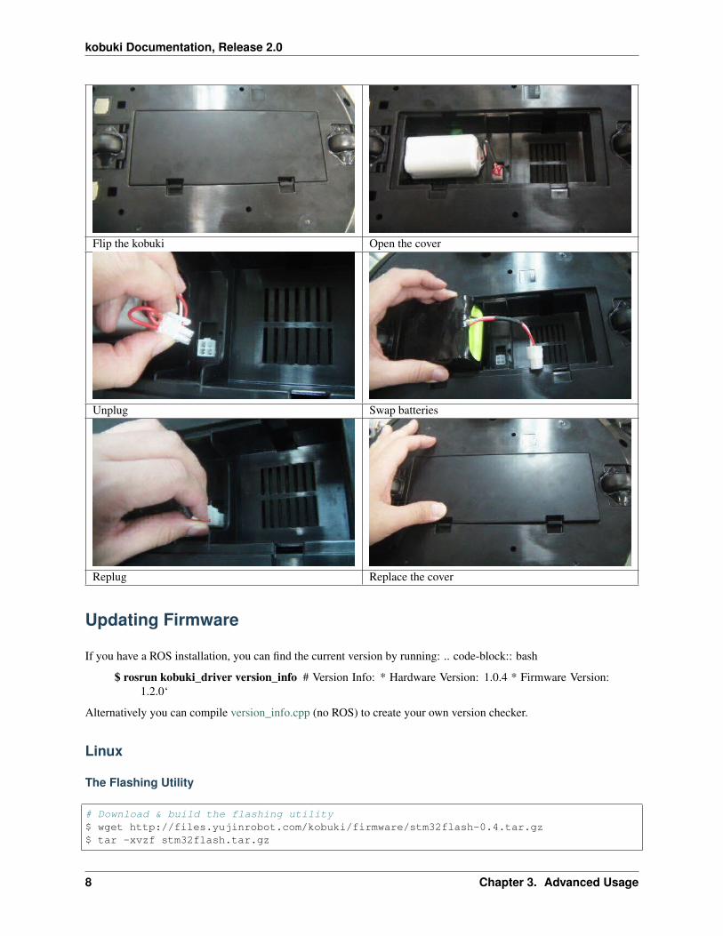
Replacing Batteries
Warning: The electronics does not support the use of multiple battery packs at the same time!
7
kobuki Documentation, Release 2.0
Flip the kobuki Open the cover
Unplug Swap batteries
Replug Replace the cover
Updating Firmware
If you have a ROS installation, you can find the current version by running: .. code-block:: bash
$ rosrun kobuki_driver version_info # Version Info: * Hardware Version: 1.0.4 * Firmware Version:1.2.0‘
Alternatively you can compile version_info.cpp (no ROS) to create your own version checker.
Linux
The Flashing Utility
# Download & build the flashing utility$ wget http://files.yujinrobot.com/kobuki/firmware/stm32flash-0.4.tar.gz$ tar -xvzf stm32flash.tar.gz
8 Chapter 3. Advanced Usage

kobuki Documentation, Release 2.0
$ cd stm32flash$ make
Download Firmware
# choose the firmware version from http://files.yujinrobot.com/kobuki/firmware# e.g. latest$ wget http://files.yujinrobot.com/kobuki/firmware/kobuki_firmware-latest.hex
Identify ttyUSBx Port
If you have a udev rule installed, it will show up as /dev/kobuki, but if not, you can typically find it under one of thettyUSB ports, e.g. /dev/ttyUSB0. If you are not sure, type dmesg into a terminal, unplug and replug the robot andtype dmesg again. You should now be able to see which port is assigned to the robot (more precisely the FTDI USBto serial converter).
Switch to Download Mode
1. Connect the robot to your PC using the USB cable
2. Turn off the robot (switch on the side)
3. Switch from normal runtime mode to firmware download mode
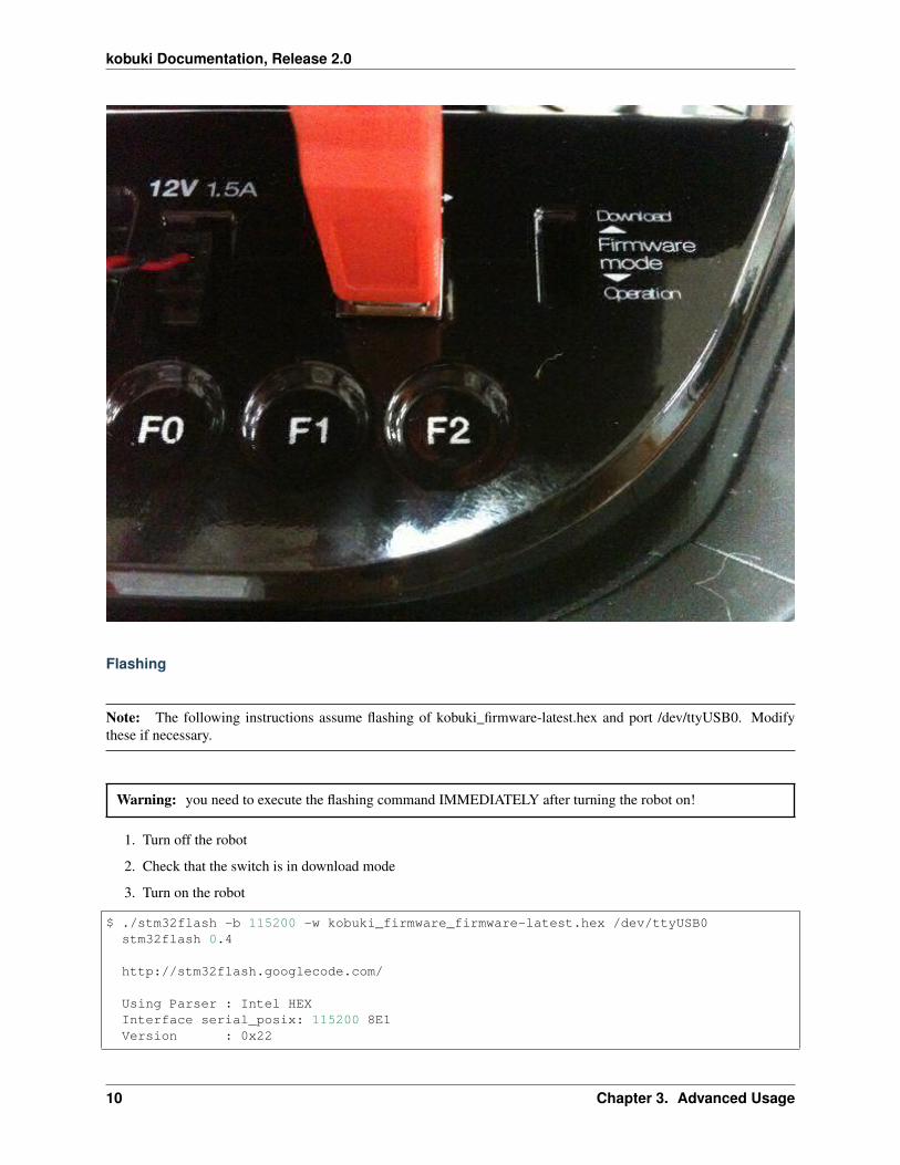
This simply changes the type of data that is sent back and forth along the usb connection. You can do this by movingthe switch illustrated below into the ‘download’ (up) position. Note that this switch is embedded into the robot coverso it isn’t easily thrown by accident – you may need thin plyers or some similar tool. You can find the mode switchmechanism on the right side of the control panel - see the image below.
3.2. Updating Firmware 9
kobuki Documentation, Release 2.0
Flashing
Note: The following instructions assume flashing of kobuki_firmware-latest.hex and port /dev/ttyUSB0. Modifythese if necessary.
Warning: you need to execute the flashing command IMMEDIATELY after turning the robot on!
1. Turn off the robot
2. Check that the switch is in download mode
3. Turn on the robot
$ ./stm32flash -b 115200 -w kobuki_firmware_firmware-latest.hex /dev/ttyUSB0stm32flash 0.4
http://stm32flash.googlecode.com/
Using Parser : Intel HEXInterface serial_posix: 115200 8E1Version : 0x22
10 Chapter 3. Advanced Usage

kobuki Documentation, Release 2.0
Option 1 : 0x00Option 2 : 0x00Device ID : 0x0414 (High-density)- RAM : 64KiB (512b reserved by bootloader)- Flash : 512KiB (sector size: 2x2048)- Option RAM : 16b- System RAM : 2KiBWrite to memoryErasing memoryWrote address 0x0800a3f0 (100.00%) Done.
Rebooting
• Turn off the robot power
• Flick the firmware switch back to ‘Operation’ mode.
• Turn on the robot power
• I’m happy, you should be too!
Windows
The Flashing Utility
• Download and install the windows flashing utility
Download Firmware
Find and download the version of the firmware you wish to flash from the Kobuki FW File Server.
Identify the COM Port
Usually if this will show up on COM1, but check to make sure.
Switch to Download Mode
1. Connect the robot to your PC using the USB cable
2. Turn off the robot (switch on the side)
3. Switch from normal runtime mode to firmware download mode
This simply changes the type of data that is sent back and forth along the usb connection. You can do this by movingthe switch illustrated below into the ‘download’ (up) position. Note that this switch is embedded into the robot coverso it isn’t easily thrown by accident – you may need thin plyers or some similar tool. You can find the mode switchmechanism on the right side of the control panel - see the image below.
3.2. Updating Firmware 11
kobuki Documentation, Release 2.0
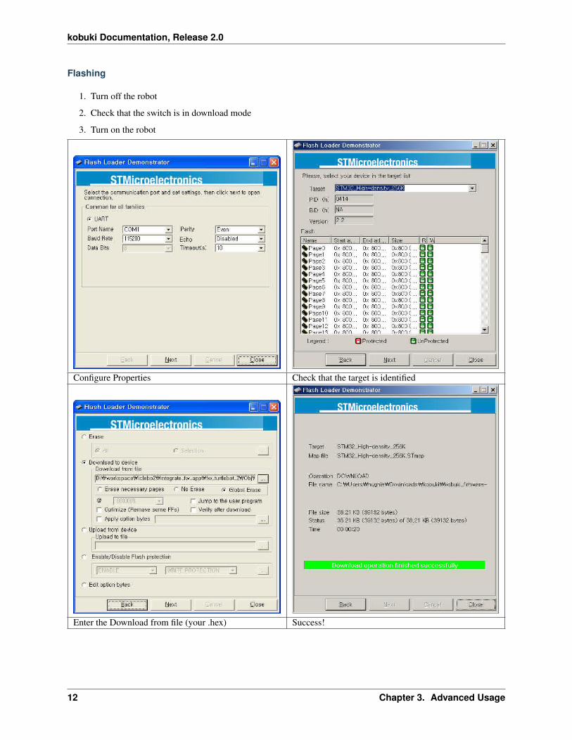
Flashing
1. Turn off the robot
2. Check that the switch is in download mode
3. Turn on the robot
Configure Properties Check that the target is identified
Enter the Download from file (your .hex) Success!
12 Chapter 3. Advanced Usage
kobuki Documentation, Release 2.0
Rebooting
• Turn off the robot power
• Flick the firmware switch back to ‘Operation’ mode.
• Turn on the robot power
• I’m happy, you should be too!
Serial Port Connectivity
Many embedded boards do not have usb interfaces, or the embedded board doesn’t have the necessary ftdi32 serial->usb support. In these cases it is simpler to utilise the serial port on Kobuki’s expansion port to driving kobuki byserial interface instead of USB.
Pinouts
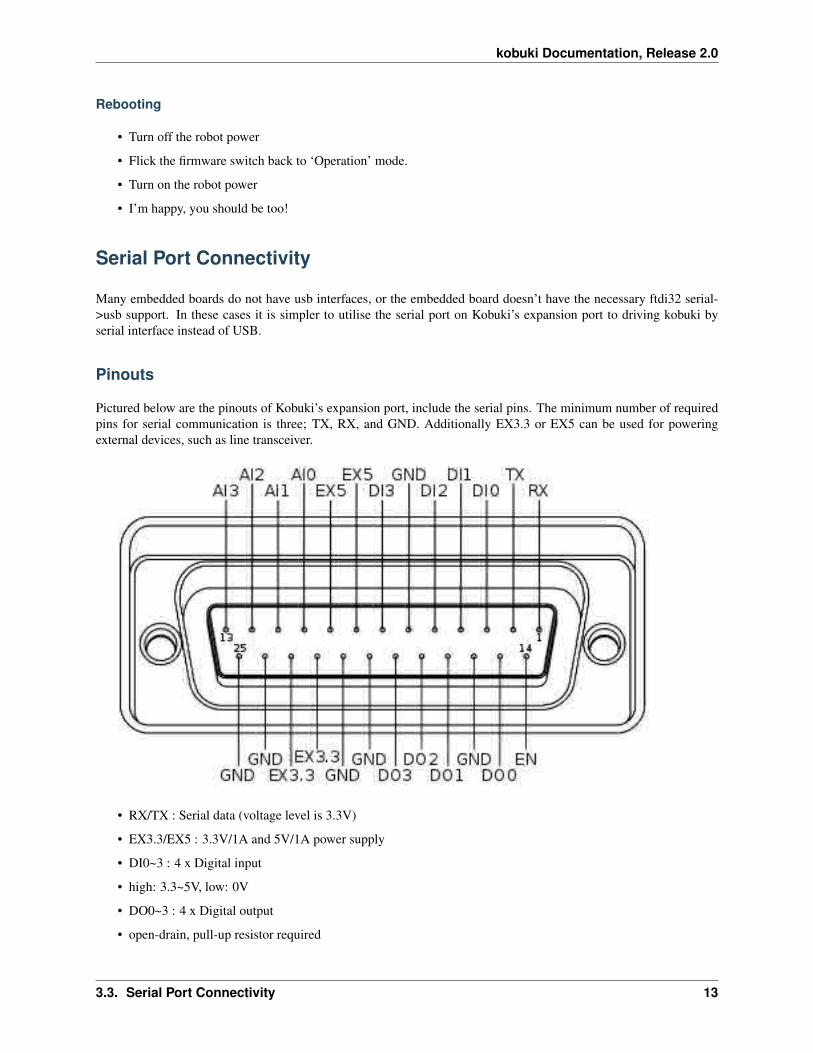
Pictured below are the pinouts of Kobuki’s expansion port, include the serial pins. The minimum number of requiredpins for serial communication is three; TX, RX, and GND. Additionally EX3.3 or EX5 can be used for poweringexternal devices, such as line transceiver.
• RX/TX : Serial data (voltage level is 3.3V)
• EX3.3/EX5 : 3.3V/1A and 5V/1A power supply
• DI0~3 : 4 x Digital input
• high: 3.3~5V, low: 0V
• DO0~3 : 4 x Digital output
• open-drain, pull-up resistor required
3.3. Serial Port Connectivity 13

kobuki Documentation, Release 2.0
• AI0~3 : 4 x Analog input
• 12bit ADC: 0~4095, 0~3.3V
• GND : Ground
• EN : Used for detecting an external board
• connect to external ground
Connections
RS-232 Interface
The voltage level of serial port is 3.3V. To connect kobuki with the standard RS-232 serial port, you should use linetransceiver in the middle to convert voltage level. MAX232 chip is typical solution for it. Below diagram showsimplified typical example of connections between Kobuki and SBC (your embedded board, laptop or pc). EX3.3 pinis used to powering line transceiver. It can be EV5 pin or external power sources from outside.
Logic Level Interface
To connect kobuki with serial port of MCU directly, below is the simplest connection diagram can be used. Serialpins of kobuki are 5V-tolerant. It accepts 3.3V and 5V voltage levels typically used by integrated circuit. Connectionwith power pin(EX3.3 or EX5) is optional, if you powering MCU with independent sources, such as battery, or walladaptor.
14 Chapter 3. Advanced Usage

kobuki Documentation, Release 2.0
Building an Application
If you’re using the ROS implementation, or building atop the kobuki c++ driver, simply re-configure the port stringused for the application and everything should be ready to go.
If building an experimental driver from scratch (e.g. android driver), then you will need to implement the KobukiProtocol specification.
3.3. Serial Port Connectivity 15

kobuki Documentation, Release 2.0
Adding a Custom Sensor Array
Kobuki usually gets equipped with a 3d sensor These typically have limitations as obstacle avoidance sensor:
• Narrow fov (58° x 43° horizontal x vertical)
• Death zone on the first 45 cm
• Cannot detect glass walls
• Cannot detect polished metallic surfaces
In one experiment an 11 IR sensors half ring, pointing 12 degrees downward was added to compensate.
• Sensor model: Sharp GP2Y0A21YK
• Power supply: Kobuki’s 5V, 1A
• Sensor reading: Arduino MEGA 2560
• PC interface: Arduino custom firmware – Bosch adc_driver
• Mounting: 3D printed frame.
The analog output of sensors is read by the Arduino board, while for power and ground they are connected to Kobuki’s5V 1A power source. Connecting several sensors to the same power supply makes readings very noisy when therearen’t obstacles. The solution was to put decoupling capacitors on each sensor. For interfacing Arduino, we use Boschadc_driver. A funny problem comes sometimes when looking at corners in a particular angle (~30 degrees) : sensorsget a spurious reading, no idea why. We just went on with this, as is not a common problem. Different mountingframes are available for downloading and printing in our file server:
• Horizontally mounted MaxBotix’s LV-Maxsonars
• Horizontally mounted Sharp IR sensors
• 12 degrees downward pointing Sharp IR sensors
And the result:
16 Chapter 3. Advanced Usage

CHAPTER 4
Specifications
Safety Guidline
• Do not twist or subject the power cable to extreme pressure or weight weight.
• Keep the pin and interface of the power plug clean from dust or water.
• Do not pull the power cord or touch the power plug with wet hands.
• Do not use with a damaged power plug, power cord or loose outlet.
• Use Kobuki indoors only.
• Do not pour or spray water onto Kobuki.
• Do not use Kobuki to pick up anything that is burning or smoking.
• Always remove the battery before long-term storage or transportation.
Functional
• Maximum translational velocity: 70 cm/s
• Maximum rotational velocity: 180 deg/s (>110 deg/s gyro performance will degrade)
• Payload: 5 kg (hard floor), 4 kg (carpet)
• Cliff: will not drive off a cliff with a depth greater than 5cm
• Threshold Climbing: climbs thresholds of 12 mm or lower
• Rug Climbing: climbs rugs of 12 mm or lower
• Expected Operating Time: 3/7 hours (small/large battery)
• Expected Charging Time: 1.5/2.6 hours (small/large battery)
• Docking: within a 2mx5m area in front of the docking station
17

kobuki Documentation, Release 2.0
Hardware
• PC Connection: USB or via RX/TX pins on the parallel port
• Motor Overload Detection: disables power on detecting high current (>3A)
• Odometry: 52 ticks/enc rev, 2578.33 ticks/wheel rev, 11.7 ticks/mm
• Gyro: factory calibrated, 1 axis (110 deg/s)
• Bumpers: left, center, right
• Cliff sensors: left, center, right
• Wheel drop sensor: left, right
• Power connectors: 5V/1A, 12V/1.5A, 12V/5A
• Expansion pins: 3.3V/1A, 5V/1A, 4 x analog in, 4 x digital in, 4 x digital out
• Audio : several programmable beep sequences
• Programmable LED: 2 x two-coloured LED
• State LED: 1 x two coloured LED [Green - high, Orange - low, Green & Blinking - charging]
• Buttons: 3 x touch buttons
• Battery: Lithium-Ion, 14.8V, 2200 mAh (4S1P - small), 4400 mAh (4S2P - large)
• Firmware upgradeable: via usb
• Sensor Data Rate: 50Hz
• Recharging Adapter: Input: 100-240V AC, 50/60Hz, 1.5A max; Output: 19V DC, 3.16A
• Netbook recharging connector (only enabled when robot is recharging): 19V/2.1A DC
• Docking IR Receiver: left, centre, right
Software
• C++ drivers for Linux
• ROS driver
• Gazebo simulation
18 Chapter 4. Specifications
CHAPTER 5
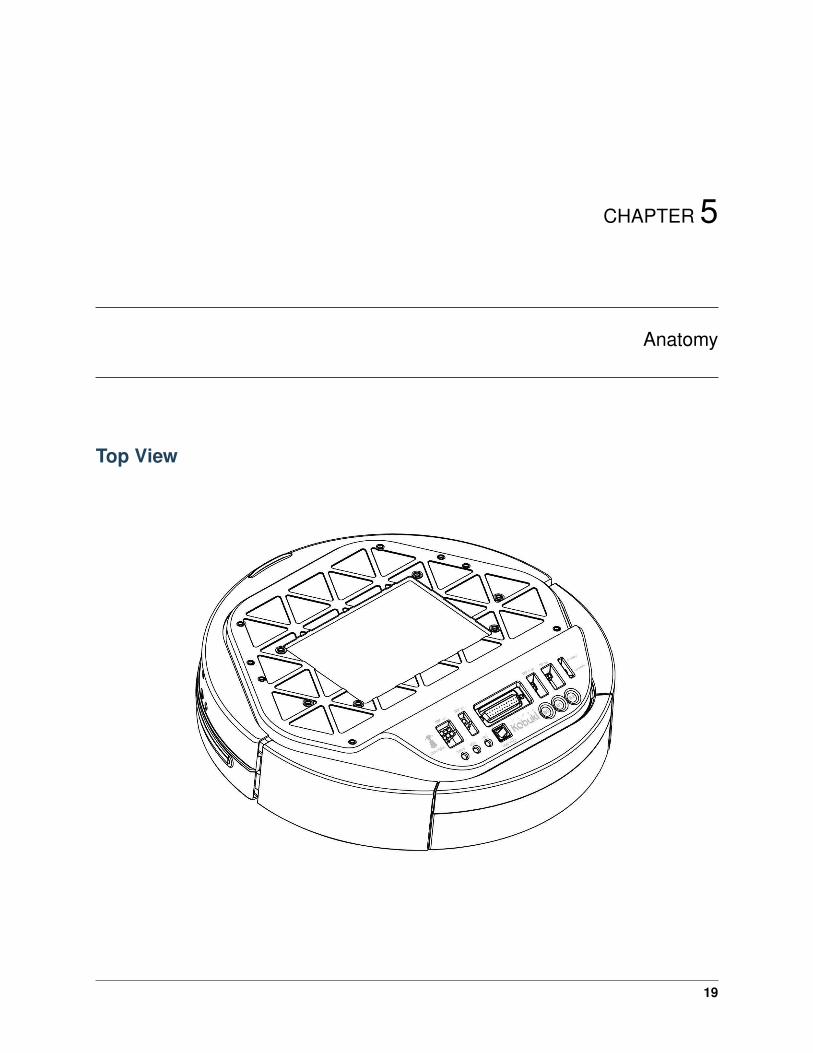
Anatomy
Top View
19
kobuki Documentation, Release 2.0
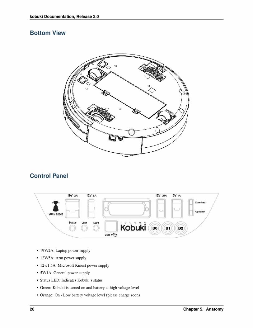
Bottom View
Control Panel
• 19V/2A: Laptop power supply
• 12V/5A: Arm power supply
• 12v/1.5A: Microsoft Kinect power supply
• 5V/1A: General power supply
• Status LED: Indicates Kobuki’s status
• Green: Kobuki is turned on and battery at high voltage level
• Orange: On - Low battery voltage level (please charge soon)
20 Chapter 5. Anatomy

kobuki Documentation, Release 2.0
• Green blinking: On - Battery charging
• Off: Kobuki is turned off.
• LED1/2: Programmable LEDs
• USB: Data connection
• BO/1/2: Buttons
• Firmware switch: Enable/disables the firmware update mode
Connectors
Note: SOME NOTES ABOUT THE MOLEX PAGES BELOW
1. We do not actually use Molex connectors but we are supplied by a Korean vendor who produces connectorsaccording to the Molex standard. These links will be more useful to internationals in helping them find a matingpart that works for them.
2. The images on each page are representative of the series of connectors. Each series usually has a variety ofconnectors with a different number of pins. As a result, the pictures on some of the pages below may seem asthough they have the incorrect number of pins, but do not worry about this – they are the correct links. Notethat you can jump to different connectors in the series via the second part of their identification number (e.g.43045-0224 for the 2-pin, 43045-0424 for the 4-pin).
3. If some linked connectors are listed as obsolete on the molex website, don’t worry. The connector you areexactly requiring are those you can find under the ‘Mates with Parts’ link on each page. If these however shouldbecome obsolete as well, please let us know via email.
Power
• 5V@1A Molex PN : 43650-0218 – for custom boards
• [email protected] : Molex PN : 43045-0224 – specially supporting the kinect
• 12V@5A : Molex PN : 3929-9023 – for high powered accessories (e.g. robotic arm)
• 19V@2A : Molex PN : 3928-9068 – for recharging netbooks
Battery
• 4S1P/4S2P Battery Pack Connector
5.4. Connectors 21
kobuki Documentation, Release 2.0
I/O Port
DB25 pin D-SUB Female connector that provides the following functionality (pdf)
Cables
Note: If you click on the preceding links for the power connectors, under the heading ‘Mates with Part(s)’ you canfind the compatible connector to use with each power source. The most important one being of course:
• [email protected] : Molex PN : 43025-0200 – specially supporting the kinect
Models & Drawings
The models and drawings include both the base and parts for the Turtlebot 2.
• 2D mechanical drawings – DWG, PDF
• 3D models – IGS, STEP
The inserts in the kobuki plate are M4 threads (metric, 4mm). If you wish to build standoffs compatible for theseinserts, please reference the pole pdf’s in the 2D mechanical drawings which are what we use for turtlebots.
Motors
Specifications
• Brushed DC Motor
• Motor Manufacturer: Standard Motor
• Part Name: RP385-ST-2060
• Rated Voltage: 12 V
• Rated Load: 5 mN·m
• No Load Current: 210 mA
• No Load Speed: 9960 rpm ± 15%
• Rated Load Current: 750 mA
• Rated Load Speed: 8800 rpm ± 15%
• Armature Resistance: 1.5506 Ω at 25°C
• Armature Inductance: 1.51 mH
• Torque Constant(Kt): 10.913 mN·m/A
• Velocity Constant(Kv): 830 rpm/V
• Stall Current: 6.1 A
• Stall Torque: 33 mN·m
22 Chapter 5. Anatomy

kobuki Documentation, Release 2.0
Control Method
• Driven by voltage source(H-bridge)
• Controlled by Pulse-width modulation(PWM)
Gyro
Specification
• 3-Axis Digital Gyroscope
• Manufacturer : STMicroelectronics
• Part Name : L3G4200D
• Measurement Range: ±250 deg/s
• Yaw axis is factory calibrated within the range of ±20 deg/s to ±100 deg/s
Performance
In-Place Rotation Test
This graph shows the average heading error per revolution of gyro, when robot rotates with a given velocity.
5.7. Gyro 23

kobuki Documentation, Release 2.0
Square Path Test
This graph shows the position error of fused odometry with gyro, when robot moves along a square path. Robot movedwith 0.1 m/s on the line segment and rotated with 30 deg/s on the corner.
This table shows the calculated angular error, when robot arrived at the diagonally opposite corner from the startingpoint (0.0, 0.0).
Number of turns of square path Angular Error [deg]0.5 0.471.5 1.992.5 3.18
24 Chapter 5. Anatomy

kobuki Documentation, Release 2.0
Power Adapter
Input Output OtherVoltage: 100-240V Voltage: 19V powerphoto PhotoFrequency: 50/60Hz Ampere: 3.16A spec1 Specification 1Ampere: 1.5A Max spec2 Specification 2
Batteries
Kobuki by the default ships with a small Lithium-Ion battery pack (4S1P, 2200mAh, 14.8V).
Note: For extra long operation, a big battery pack (4S2P, 4400mAh, 14,8V) can be ordered as well.
Warning: The electronics does not support the use of multiple battery packs at the same time (even if there isroom in the battery compartment)
Specifications
• Data Sheet (pdf)
Pinouts
• Red: battery (+), 9.6 V ~ 16.8 V
• White: NTC thermistor to ground, 10 kΩ ± 1%
• Black: battery(-), Ground
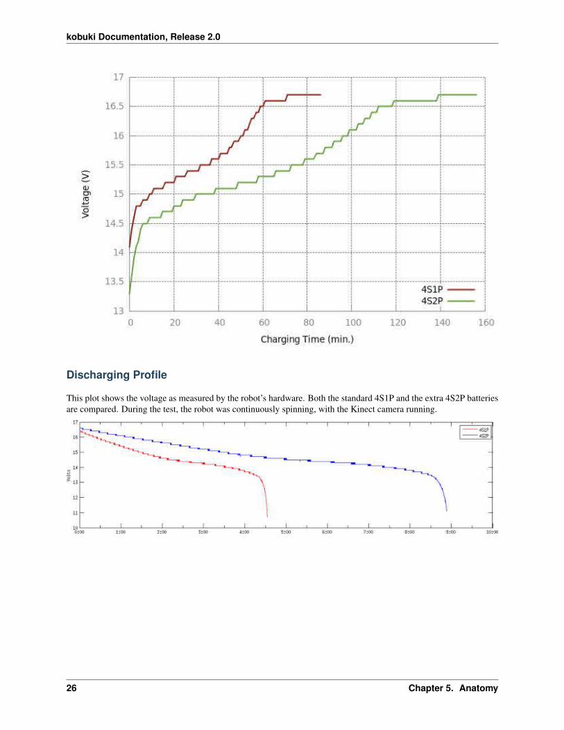
Charing Profile
This plot shows the voltages as measured by the robot’s hardware. Both the standard 4S1P and the extra 4S2P batteriesare compared. During the test, the robot was charging via adaptor.
5.8. Power Adapter 25
kobuki Documentation, Release 2.0
Discharging Profile
This plot shows the voltage as measured by the robot’s hardware. Both the standard 4S1P and the extra 4S2P batteriesare compared. During the test, the robot was continuously spinning, with the Kinect camera running.
26 Chapter 5. Anatomy
kobuki Documentation, Release 2.0
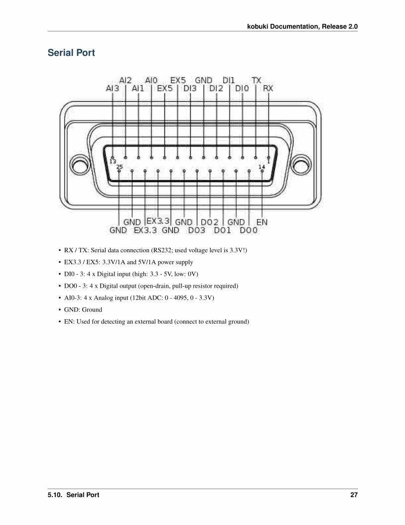
Serial Port
• RX / TX: Serial data connection (RS232; used voltage level is 3.3V!)
• EX3.3 / EX5: 3.3V/1A and 5V/1A power supply
• DI0 - 3: 4 x Digital input (high: 3.3 - 5V, low: 0V)
• DO0 - 3: 4 x Digital output (open-drain, pull-up resistor required)
• AI0-3: 4 x Analog input (12bit ADC: 0 - 4095, 0 - 3.3V)
• GND: Ground
• EN: Used for detecting an external board (connect to external ground)
5.10. Serial Port 27
kobuki Documentation, Release 2.0
28 Chapter 5. Anatomy

CHAPTER 6
Firmware
Communication
• Baud rate: 115200 BPS, Data bit: 8 bit, Stop bit: 1 bit, No Parity
• Electronic protocol: USB / RS232 (@ DB25 connector)
Protocol Specification
The driver communicates with the robot by using predefined protocol. In general, the driver sends the commands tothe robot and the robot sends some feedback data or sensor readings. This command and feedback data are convertedinto bytestreams for communication via serial interface. The protocol specify that rules and forms of bytestream.
For more detailed information, visit: - http://yujinrobot.github.com/kobuki/enAppendixProtocolSpecification.html
Version Checking
Every time the robot comes alive (because it is connected or powered on), the driver checks the compatibility betweensoftware (i.e. driver) and firmware. Firmware versions are of the form M.m.p, where:
• M(ajor) represents a deep rebuild of the code that almost surely breaks protocol compatibility. In consequence,if mayor version doesn’t match, the driver will show an error, suggest the required update and shutdown.
• m(inor) represents a new feature that could not work if the driver is outdated, but the protocol itself is spared.In consequence, if minor version doesn’t match, the driver will show a warning suggesting the required updateand continue working.
• p(atch) represents a fix on the code and is not checked at all.
You can check which firmware version your robot is running on the log (check the first lines on stdout at driverstartup), by running the version_info program included on the kobuki driver, or if you are using ROS, just echoing
29
kobuki Documentation, Release 2.0
/mobile_base/version_info topic. Generally speaking, it’s recommended to upgrade the firmware to the latest stableversion.
Special Firmware Modes
Activating
Kobuki has some special firmware modes, which can be activated on startup. Currently implemented are: #. Randomwalker mode #. Arduino/Embedded board support mode
To activate one of them, follow these instructions: #. Turn on Kobuki. #. Within in the first 3 seconds press and holdbutton BO(I) / B1 (II) for 2 seconds. #. If you see LED2(I) / LED1(II) switching between red and green, your chosenmode is activated.
Note: These modes have been introduced to the firmware with version 1.1.0. In case your Kobuki is not running thisor a later version, please refer to the section about updating the firmware.
Random Walker Mode
In the random walker mode Kobuki is driving around until it hits an object with the bumper or a cliff is detected. Inboth cases, Kobuki will stop, turn by a random amount of degrees and continue driving .
Note: In this mode Kobuki’s wheel drop sensors are not activated. So, be careful when lifting up Kobuki!
Arduino / Embedded Board Support Mode
In this mode the serial port (DB25 connector) gives access to basic controls of Kobuki. You can hook up the digi-tal/analog inputs/outpus of your Arduino or other embedded boards and start writing simple control programs.
Below is the special pin setting listed. Please refer to the serial port description for the name to pin mapping. - DI0:Not used - DI1: Not used - DI2: Not used - DI3: Not used - DO0: Bumper left (pressed/released) - DO1: Bumpercentre (pressed/released) - DO2: Bumper right (pressed/released) - DO3: Wheel drop sensors (at least one wheel isdropped / none is dropped) - AI0: Wheel speed right (0V - full speed backward, 3.3V - full speed forward) - AI1:Wheel speed left (0V - full speed backward, 3.3V - full speed forward) - AI2: Not used - AI3: Not used
All other pins (GND, RX, TX etc.) remain unchanged.
Note: To enable the motors you need to press button B0.
30 Chapter 6. Firmware

CHAPTER 7
Resources
• Kobuki Images & Renderings
• Turtlebot Images & Renderings
• Marketing Materials
31

kobuki Documentation, Release 2.0
32 Chapter 7. Resources

CHAPTER 8
Changelog
• 1.0.0 : official release
• 1.0.1 : upgrading firmware link fix
• 1.0.2 : documentation link fix
• 1.0.4 : updating the spec. of serial communication
• 1.0.5 : fixing battey & connector link
• 1.0.6 : updating link after Kobuki web site revision
• 1.1.0 : reorganised and collapsed website howtos into the guide
• 2.0.0 : Port to sphinx, readthedocs, and rst2pdf
33

kobuki Documentation, Release 2.0
34 Chapter 8. Changelog

CHAPTER 9
License
The Kobuki user guide is licensed under a Creative Commons Attribution-ShareAlike 3.0 Unported License.
35

kobuki Documentation, Release 2.0
36 Chapter 9. License
CHAPTER 10
Frequently Asked Questions
37
kobuki Documentation, Release 2.0
38 Chapter 10. Frequently Asked Questions

CHAPTER 11
Contact
This documentation is copied from the Kobuki User Guide provided by Yujin, and formatted into a reStructuredTextdocument using Sphinx.
Except where otherwise noted, these design documents are licensed under Creative Commons Attribution 4.0 Interna-tional License.
39


