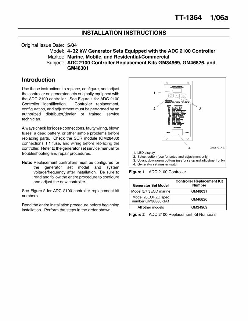
INSTALLATION INSTRUCTIONS TT-1364 1/06a Original Issue Date: 5/04 Model: 4--32 kW Generator Sets Equipped with the ADC 2100 Controller Market: Marine, Mobile, and Residential/Commercial Subject: ADC 2100 Controller Replacement Kits GM34969, GM46826, and GM48301 Introduction Use these instructions to replace, configure, and adjust the controller on generator sets originally equipped with the ADC 2100 controller. See Figure 1 for ADC 2100 Controller identification. Controller replacement, configuration, and adjustment must be performed by an authorized distributor/dealer or trained service technician. Always check for loose connections, faulty wiring, blown fuses, a dead battery, or other simple problems before replacing parts. Check the SCR module (GM28483) connections, F1 fuse, and wiring before replacing the controller. Refer to the generator set service manual for troubleshooting and repair procedures. Note: Replacement controllers must be configured for the generator set model and system voltage/frequency after installation. Be sure to read and follow the entire procedure to configure and adjust the new controller. See Figure 2 for ADC 2100 controller replacement kit numbers. Read the entire installation procedure before beginning installation. Perform the steps in the order shown. 1 2 4 3 1. LED display 2. Select button (use for setup and adjustment only) 3. Up and down arrow buttons (use for setup and adjustment only) 4. Generator set master switch GM28707A-C Figure 1 ADC 2100 Controller Generator Set Model Controller Replacement Kit Number Model 5/7.3ECD marine GM48031 Model 20EORZD spec number GM38880-SA1 GM46826 All other models GM34969 Figure 2 ADC 2100 Replacement Kit Numbers
Transcript
INSTALLATION INSTRUCTIONS
TT-1364 1/06a
Original Issue Date: 5/04
Model: 4--32 kW Generator Sets Equipped with the ADC 2100 Controller
Market: Marine, Mobile, and Residential/Commercial
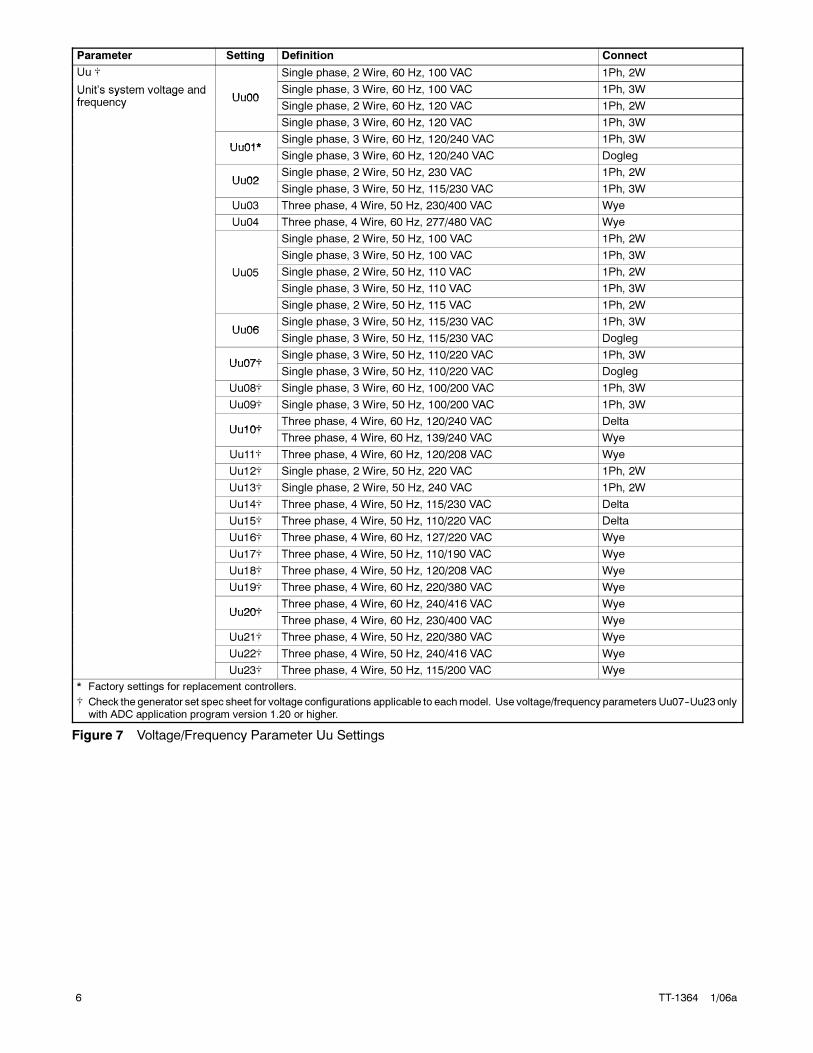
Uu14� Three phase, 4 Wire, 50 Hz, 115/230 VAC Delta
Uu15� Three phase, 4 Wire, 50 Hz, 110/220 VAC Delta
Uu16� Three phase, 4 Wire, 60 Hz, 127/220 VAC Wye
Uu17� Three phase, 4 Wire, 50 Hz, 110/190 VAC Wye
Uu18� Three phase, 4 Wire, 50 Hz, 120/208 VAC Wye
Uu19� Three phase, 4 Wire, 60 Hz, 220/380 VAC Wye
Uu20�Three phase, 4 Wire, 60 Hz, 240/416 VAC Wye
Uu20�Three phase, 4 Wire, 60 Hz, 230/400 VAC Wye
Uu21� Three phase, 4 Wire, 50 Hz, 220/380 VAC Wye
Uu22� Three phase, 4 Wire, 50 Hz, 240/416 VAC Wye
Uu23� Three phase, 4 Wire, 50 Hz, 115/200 VAC Wye
* Factory settings for replacement controllers.
� Check the generator set spec sheet for voltage configurations applicable to eachmodel. Use voltage/frequency parameters Uu07--Uu23 onlywith ADC application program version 1.20 or higher.
Communications Cn01 J1939 (use for Remote Digital Gauge)
Cn02 � Smartcraft� gauge for generator set #1
Cn03 � Smartcraft� gauge for generator set #2
Cn04 � Smartcraft� gauge for generator set #3
Cn05 � Smartcraft� gauge for generator set #4
Cn06 Reserved for future development
* Factory settings for replacement controllers.
� Setting the Ec parameter automatically selects the appropriate Ed parameter for the standard data input types for that engine. Change thisparameter if optional senders are installed. See Figure 9.
� Smartcraft� settings for ADC code version 2.xx only, for models 5/7.3ECD and 4/6EFCD
Figure 8 Controller Parameters
8 TT-1364 1/06a
Parameter Low Coolant Level Sensor Pressure Sensor Temperature Sensor Magnetic Pickup
Ed00 Digital Digital Digital No
Ed01 Digital Digital Analog No
Ed02 Digital Analog Digital No
Ed03 Digital Analog Analog No
Ed04 Digital Digital Digital Yes
Ed05 * Digital Digital Analog Yes
Ed06 Digital Analog Digital Yes
Ed07 Digital Analog Analog Yes
Ed08 Analog Digital Digital No
Ed09 Analog Digital Analog No
Ed10 Analog Analog Digital No
Ed11 Analog Analog Analog No
Ed12 Analog Digital Digital Yes
Ed13 Analog Digital Analog Yes
Ed14 Analog Analog Digital Yes
Ed15 Analog Analog Analog Yes
* Factory setting for replacement controllers. See Figure 8 for the default settings for certain models. The installation of optional sender kits(available for some models) may require a different Ed setting.
Figure 9 Engine Data Input Types, Parameter Ed
TT-1364 1/06a 9
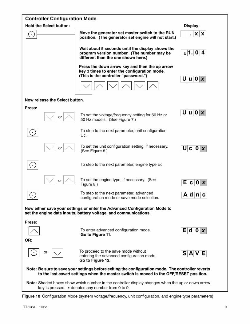
UWait about 5 seconds until the display shows theprogram version number. (The number may bedifferent than the one shown here.)
Hold the Select button:
orTo set the voltage/frequency setting for 60 Hz or50 Hz models. (See Figure 7.)
To step to the next parameter, unit configurationUc.
or To set the unit configuration setting, if necessary.(See Figure 8.)
To step to the next parameter, engine type Ec.
To step to the next parameter, advancedconfiguration mode or save mode selection.
Move the generator set master switch to the RUNposition. (The generator set engine will not start.)
Display:
or To set the engine type, if necessary. (SeeFigure 8.)
U u 0 x
U c 0 x
U u 0 x
1. 0 4
. x x
A d n c
Press:
Now release the Select button.
OR:
To enter advanced configuration mode.Go to Figure 11.
or To proceed to the save mode withoutentering the advanced configuration mode.Go to Figure 12.
Now either save your settings or enter the Advanced Configuration Mode toset the engine data inputs, battery voltage, and communications.
Press:
S A V E
E d 0 x
E c 0 x
Note: Be sure to save your settings before exiting the configurationmode. The controller reverts
to the last saved settings when the master switch is moved to the OFF/RESET position.
Note: Shaded boxes show which number in the controller display changes when the up or down arrow
key is pressed. x denotes any number from 0 to 9.
Press the down arrow key and then the up arrowkey 3 times to enter the configuration mode.(This is the controller “password.”)
Controller Configuration Mode
Figure 10 Configuration Mode (system voltage/frequency, unit configuration, and engine type parameters)
10 TT-1364 1/06a
or To set the engine data input type.
To enter battery voltage selection mode.
or To toggle between 12 and 24 VDC.
To enter communications selection mode.
orTo set the communications parameter.(See Figure 8.)
To enter SAVE mode. Go to Figure 12.
E d 0 x
Pressing the up arrow key at the Adnc display (See Figure 10) puts you intothe Advanced Configuration Mode.
Press:
B t 1 2
C n 0 x
S A V E
B t 2 4
12-volt models
24-volt models
Note: Be sure to save your settings before exiting the configurationmode. The controller reverts
to the last saved settings when the master switch is moved to the OFF/RESET position.
Note: Shaded boxes show which number in the controller display changes when the up or down arrow
key is pressed. x denotes any number from 0 to 9.
Note: Setting the Ec parameter automatically selects the appropriate Ed
parameter for the standard senders for that engine. See Figure 9.
Figure 11 Advanced Configuration Mode (engine data input types, battery voltage, and engine communications)
To save changes.
To discard changes without saving.
or
* x in the runtime hours display above denotes any number from 0 to 9.
S A V E
Y E S
Now move the master switch to OFF/RESET.
n o
There are 3 options when the display says SAVE:Press:
x x xx
or
To return to the first parameter to check or change settingsbefore saving. See Figure 10.
U u 0 x
“Yes”or “no” flashes when the up or down arrow ispressed and then the controller exits the configurationmode. The display returns to the runtime hours.
Figure 12 Save Mode (after configuring generator set parameters)
TT-1364 1/06a 11
TP6196
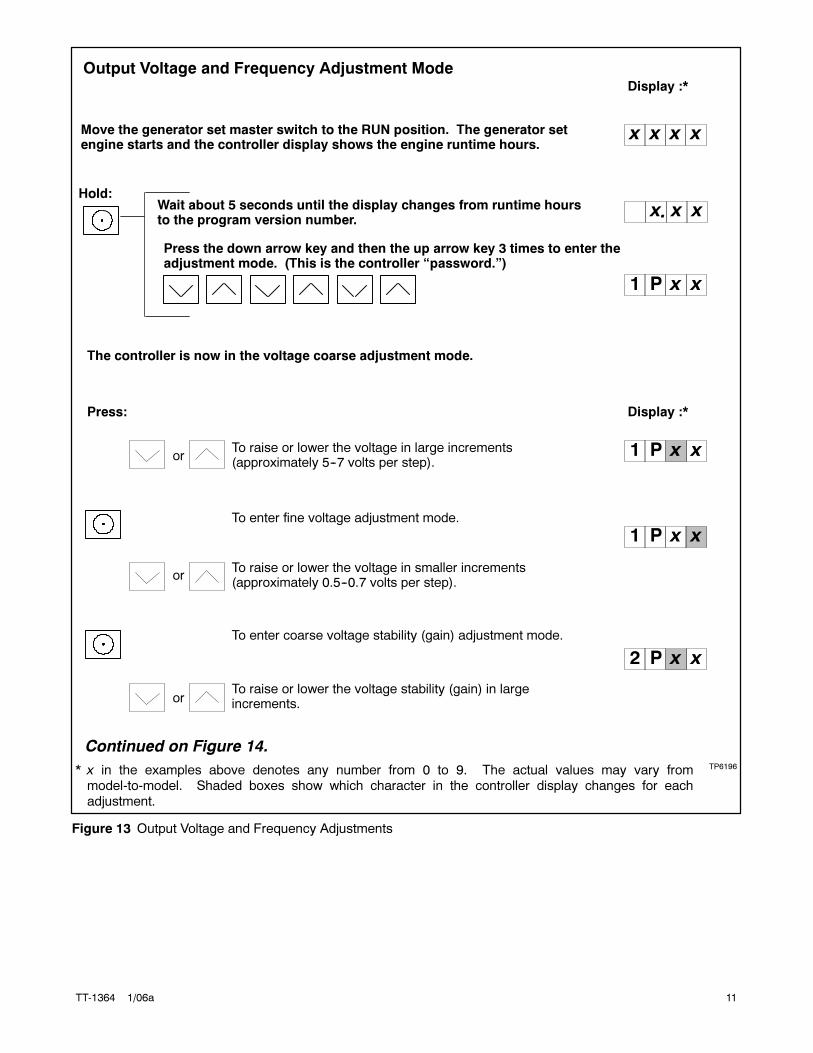
Move the generator set master switch to the RUN position. The generator setengine starts and the controller display shows the engine runtime hours.
Display :*
or
or
To raise or lower the voltage in large increments(approximately 5--7 volts per step).
To enter fine voltage adjustment mode.
To raise or lower the voltage in smaller increments(approximately 0.5--0.7 volts per step).
To enter coarse voltage stability (gain) adjustment mode.
To raise or lower the voltage stability (gain) in largeincrements.
or
Hold:Wait about 5 seconds until the display changes from runtime hoursto the program version number.
Press the down arrow key and then the up arrow key 3 times to enter theadjustment mode. (This is the controller “password.”)
x x
x x x x
1 P
1 P
2 P
* x in the examples above denotes any number from 0 to 9. The actual values may vary frommodel-to-model. Shaded boxes show which character in the controller display changes for eachadjustment.
x.
The controller is now in the voltage coarse adjustment mode.
Press:
1 P
Continued on Figure 14.
x x
x x
xx
x x
Output Voltage and Frequency Adjustment Mode
Display :*
Figure 13 Output Voltage and Frequency Adjustments
12 TT-1364 1/06a
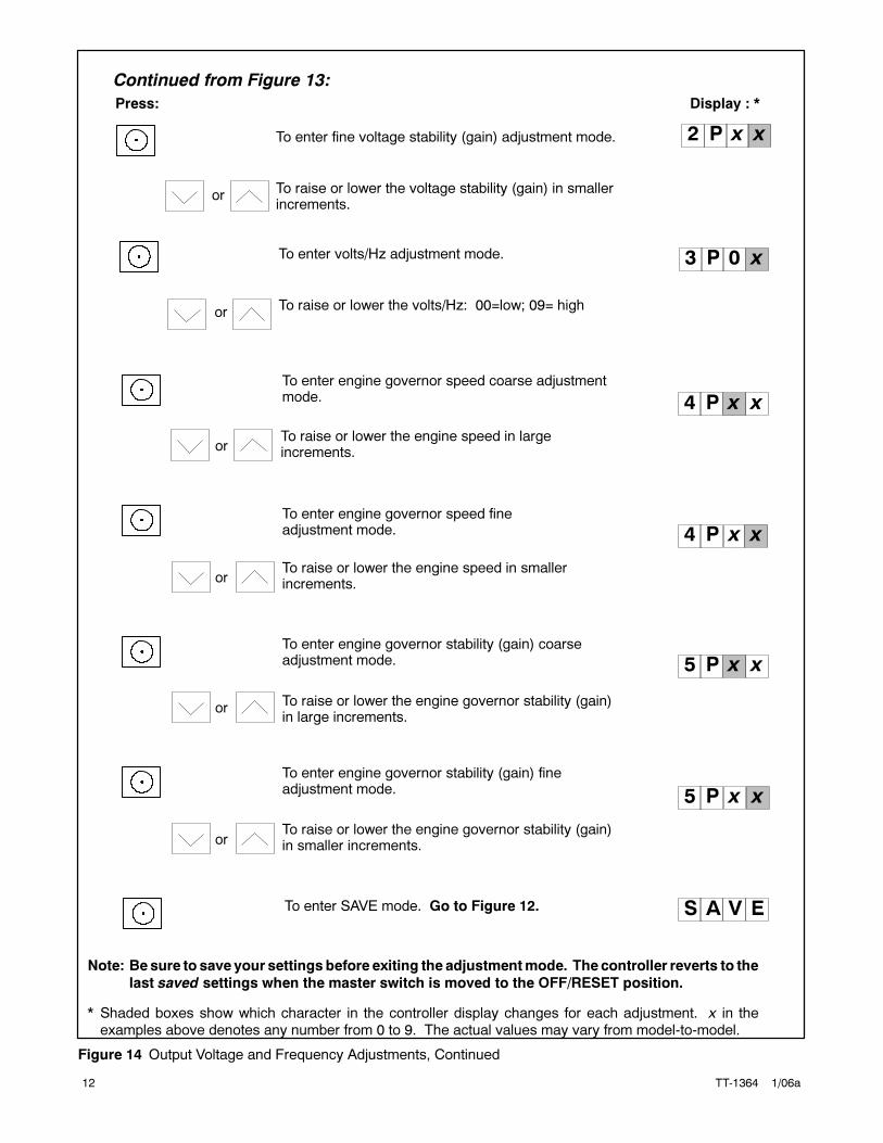
Display : *
or
To enter engine governor speed coarse adjustmentmode.
To raise or lower the engine speed in largeincrements.
To enter engine governor stability (gain) coarseadjustment mode.
To raise or lower the engine governor stability (gain)in large increments.
To enter engine governor speed fineadjustment mode.
To raise or lower the engine speed in smallerincrements.
To enter engine governor stability (gain) fineadjustment mode.
To raise or lower the engine governor stability (gain)in smaller increments.
4 P
4 P
or
or
or
Continued from Figure 13:
Press:
5 P
5 P
Note: Be sure to save your settings before exiting the adjustmentmode. The controller reverts to the
last saved settings when the master switch is moved to the OFF/RESET position.
* Shaded boxes show which character in the controller display changes for each adjustment. x in theexamples above denotes any number from 0 to 9. The actual values may vary from model-to-model.
S A V ETo enter SAVE mode. Go to Figure 12.
x x
xx
x x
xx
or
To enter volts/Hz adjustment mode.
To raise or lower the volts/Hz: 00=low; 09= high
3 P 0 x
or
To enter fine voltage stability (gain) adjustment mode.
To raise or lower the voltage stability (gain) in smallerincrements.
2 P xx
Figure 14 Output Voltage and Frequency Adjustments, Continued