21
Koike Aronson, Inc./Ransome www.koike.com Doc. No. MI0565A Rev. A 585-492-2400

Koike Aronson, Inc./Ransomewww.koike.com Doc. No. MI0565A Rev. A585-492-2400

Monograph Extreme Technical Manual
i
CONTENTS
1. Safety ...........................................................................................................1
Notes, Cautions, and Warnings .......................................................................................................2
Symbols and Warning Labels............................................................................................................ 2
General Safety ...............................................................................................................................3
Safe Workspace ............................................................................................................................... 3
Electrical Hazards............................................................................................................................. 3
Electrical Connection and Supplemental Grounding......................................................................... 4
Fire and Explosion Prevention.......................................................................................................... 4
Compressed Gas Safety.................................................................................................................... 5
Personal Protective Equipment........................................................................................................ 6
Safety, Plasma Cutting....................................................................................................................7
2. Introduction..................................................................................................8
3. Component Identification .............................................................................8
Machine Specifications...................................................................................................................9
4. Pre-Installation Requirements ....................................................................10
Location Selection ........................................................................................................................10
Site Preparation ...........................................................................................................................10
Utility Requirements ....................................................................................................................10
Electrical Requirements ................................................................................................................. 10
Fuel Requirements......................................................................................................................... 11
Air Requirements........................................................................................................................... 11
Water Requirements ..................................................................................................................... 11
Grounding Requirements .............................................................................................................11
5. Installation..................................................................................................12
Handling and Storage ...................................................................................................................12
Unpacking and Cleaning ...............................................................................................................12
CNC Interface ...............................................................................................................................13
Plasma Connections .....................................................................................................................14

Monograph Extreme Technical Manual
ii
6. Operation ...................................................................................................15
Manual Controls...........................................................................................................................15
Torch Station ................................................................................................................................. 15
7. Maintenance...............................................................................................16
Replacement Parts .......................................................................................................................16
8. Contact Information....................................................................................16
On the Web: http://www.koike.com/...........................................................................................16
Figure 1 Glossary of Symbols ................................................................................................................... 2
Figure 2 Component Identification .......................................................................................................... 8
Figure 3 CNC Configuration.................................................................................................................... 13
Figure 4 PowerMax 105 Plasma Connections......................................................................................... 14
Figure 5 MaxPro 200 Plasma Connections ............................................................................................. 14
Figure 6 Operator Control Panel ............................................................................................................ 15
Figure 7 Torch Lifter .............................................................................................................................. 15
Monograph Extreme Technical Manual
1
1. SafetyThe most important thing to know about operating this cutting machine is how to operate it safely. It is
the responsibility of the user to become familiar with the operation of this machine and to take
precautions that will ensure safety of themselves and those in the surrounding area. Mechanical,
electrical, and chemical dangers are present on this machine.
Read and understand this manual before attempting to operate this cutting machine and follow all
safety precautions.
This cutting machine should be maintained and repaired by qualified technicians. Parts that are broken,
worn, distorted, or contaminated should be replaced immediately. Koike Aronson, Inc. / Ransome
recommends that a request for service be made to either your Koike Aronson authorized dealer or to
the Koike Aronson service department directly.
This is not a complete list of all safety precautions. Local, state, and federal regulations shall also be
followed. In addition, read and follow manuals provided with equipment integrated with this unit.

Monograph Extreme Technical Manual
2
Notes, Cautions, and WarningsThis manual contains notes, cautions, and warnings that the operator is advised to follow. These are to
call special attention to conditions that can lead to unsafe situations.
Symbols and Warning Labels
Symbols and warning labels are used in this manual and on the unit to identify specific dangers involved
in the operation of this unit. Below is a glossary of symbols and their meaning.
Take Note Electrical Hazard
Poison/Toxic Gas Hazard Flammable/Combustible Hazard
Explosion Hazard Eye Exposure Hazard
Open Gear Hazard Ground Unit
Compressed Gas Hazard Eye Protection Required
Use an Approved Respirator Wear Approved Hearing Protection
Insulated Gloves Required Insulated Footwear Required
No Open Flames Hot Surface Do Not Touch
Do Not Remove Guards Wear Proper Welding Equipment
Wear Proper Clothing Beware of Cutting Tools
Figure 1 Glossary of Symbols
Monograph Extreme Technical Manual
3
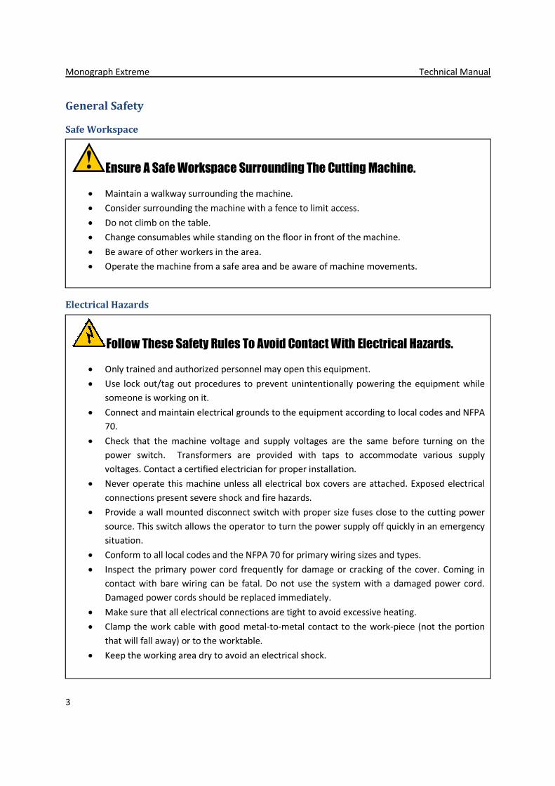
General Safety
Safe Workspace
Electrical Hazards
Follow These Safety Rules To Avoid Contact With Electrical Hazards.
Only trained and authorized personnel may open this equipment.
Use lock out/tag out procedures to prevent unintentionally powering the equipment while
someone is working on it.
Connect and maintain electrical grounds to the equipment according to local codes and NFPA
70.
Check that the machine voltage and supply voltages are the same before turning on the
power switch. Transformers are provided with taps to accommodate various supply
voltages. Contact a certified electrician for proper installation.
Never operate this machine unless all electrical box covers are attached. Exposed electrical
connections present severe shock and fire hazards.
Provide a wall mounted disconnect switch with proper size fuses close to the cutting power
source. This switch allows the operator to turn the power supply off quickly in an emergency
situation.
Conform to all local codes and the NFPA 70 for primary wiring sizes and types.
Inspect the primary power cord frequently for damage or cracking of the cover. Coming in
contact with bare wiring can be fatal. Do not use the system with a damaged power cord.
Damaged power cords should be replaced immediately.
Make sure that all electrical connections are tight to avoid excessive heating.
Clamp the work cable with good metal-to-metal contact to the work-piece (not the portion
that will fall away) or to the worktable.
Keep the working area dry to avoid an electrical shock.
Ensure A Safe Workspace Surrounding The Cutting Machine.
Maintain a walkway surrounding the machine.
Consider surrounding the machine with a fence to limit access.
Do not climb on the table.
Change consumables while standing on the floor in front of the machine.
Be aware of other workers in the area.
Operate the machine from a safe area and be aware of machine movements.

Monograph Extreme Technical Manual
4
Electrical Connection and Supplemental Grounding
The electrical connection for this equipment must conform to local codes and the NFPA 70.
Improper installation can lead to equipment malfunction and personal injury.
For a plasma system, supplemental ground rods are required to be connected to earth potential for
proper grounding of this equipment. See section Site Preparation for more information about
supplemental grounding rods.
Caution: Do not connect a welding ground to any part of this machine. Doing so will damage
the electronic controls of this machine. Evidence of welding ground connection to this machine will void
any warranty.
Fire and Explosion Prevention
To Prevent Fire And Explosion, The Installation And Use Of This
Equipment Must Be In Compliance With The Latest Editions Of The Following
Standards:
National Fire Protection Association (NFPA) Standard 51B: STANDARD FOR FIRE PREVENTION
DURING WELDING, CUTTING, AND OTHER HOT WORK
National Fire Protection Association (NFPA) Standard 51: STANDARD FOR THE DESIGN AND
INSTALLATION OF OXYGEN-FUEL GAS SYSTEMS FOR WELDING, CUTTING, AND ALLIED
PROCESSES
American Welding Society (AWS) Standard C4.2/C4.2M:2009, Recommended Practices for
Safe Oxyfuel Gas Cutting Torch Operation
Fire Prevention Tips:
Keep combustibles away from the work area or protect them from sparks and flames.
Never use oxygen to ventilate the area or clean off clothing.
Keep oil, grease, and combustible dust away from all oxygen equipment.
Purge oxygen and fuel lines individually whenever combustible mixtures in the lines are
suspected.
Never use the oxygen hose for any other gas than oxygen.

Monograph Extreme Technical Manual
5
Compressed Gas Safety
Gas Cylinders Can Explode If Damaged. Below Are Some Rules To Follow
To Ensure Safe Handling Of Gas Cylinders:
Handle and use compressed gas cylinders in accordance with safety standards published by
the Compressed Gas Association (CGA), and Canadian Standards Association (CSA).
Never use a cylinder that leaks or is physically damaged.
Never use a cylinder that is not upright and secured in place.
Never move or transport a cylinder without the protective valve cover in place.
Never use a gas cylinder or its contents for any purpose other than that for which it is
intended.
Never lubricate cylinder valves with oil or grease.
Never expose cylinders to excessive heat, sparks, slag, or open flame.
Never use hammers, wrenches, or other tools to open stuck cylinder valves.
Never cover the gas panel without venting the bottom of the cover. Fuel gases are heavier
than air.
Use only correct gas cylinders, regulators, hoses, and fittings designed for the specific
application.
Label and color-code all gas hoses to identify the type of gas in each hose.
Check for proper function of check valves regularly. Do not remove or bypass check valves.
Always open gas valves slowly.
Replace hoses that are damaged by physical abuse or by sparks, heat, or open flame.

Monograph Extreme Technical Manual
6
Personal Protective Equipment
Limit Your Exposure To Hazards.
Eye protection must be worn at all times while operating this equipment.
Cutting will produce sound pressure that causes permanent hearing damage. Properhearing protection must be worn to avoid permanent hearing loss.
Proper clothing and personal protective devices must be worn to prevent burns
and damage to vision.
A helmet with the proper filter plate must be worn for eye and face protectionwhile cutting. For plasma cutting the plate must conform to the following:
Arc Current Up to 100 Amps Shade No. 8Arc Current 100 to 200 Amps Shade No. 10Arc Current 200 to 400 Amps Shade No. 12Arc Current Over 400 Amps Shade No. 14

Monograph Extreme Technical Manual
7
Safety, Plasma Cutting
Plasma Arc
The plasma arc produces intense heat, visible, and invisible radiation. Follow the rules below
to avoid injury.
Use eye and skin protection when working with plasma cutting equipment.
Facilities should be available for the medical treatment of arc flashes or burns to the eyes.
Wear proper breathing mask when cutting galvanized metal and use proper
ventilation.
Make fire extinguishers available in the cutting area.
Remove combustible material from the immediate cutting area.
Quench freshly cut metal or allow metal to cool before handling it or bringing it in contact
with combustible materials.
Do not pick up the work piece, including the waste cutoff, while you cut. Leave the work-
piece in place or on the worktable with the work cable attached at all times.
Before changing the torch parts, disconnect the main power supply. After changing the torch
parts and returning the retaining cap to its operating position, plug the power supply in
again.
When using a water table to confine slag etc. while plasma arc cutting plate, especially
aluminum or magnesium, cutting may cause an accumulation of explosive gas below the
plate. Do not allow aluminum or magnesium dross to accumulate in a water table.
Read and follow the safety instructions provided with your plasma supply.

Monograph Extreme Technical Manual
8
2. IntroductionThis technical manual provides general installation, operation, maintenance, and service information for
the Koike Aronson, Inc. / Ransome: Monograph Extreme cutting machine.
3. Component Identification
Figure 2 Component Identification
1 Rail Assemblies
2 Table Assembly
3 Transverse Beam Assembly
4 Saddle Assembly
5 Outboard Roller
6 X-Axis Drive Assembly
7 Y-Axis Drive Assembly
8 Operator Control Console
9 Limit Switches
10 Torch Station (Master)
A Overall Machine Length
B Overall Machine Width

Monograph Extreme Technical Manual
9
Machine Specifications
Table 1 Machine Specifications
MODEL 510 512 520 610 612 620
Units
Effective Cutting Width in 60 60 60 72 72 72
Total Machine Width in 84 84 84 96 96 96
Effective Cutting Length in 120 144 240 120 144 240
Total Machine Length in 183 207 303 183 207 303
Rapid Traverse Speed ipm 1000 1000 1000 1000 1000 1000
Machine Voltage and CurrentRequirements
Voltage: 100 VAC to 240 VACCurrent: single-phase, 10.0 A at 100 VAC/4.1 A at 240 VACFrequency: 50/60 Hz
Plasma Voltage and CurrentRequirements
This will be based on the plasma power supply. Pleaserefer to the provided user manual.
Air Requirementpsi This will be based on the plasma power supply. Please
refer to the provided user manual.
Water Requirement psi Not required for this machine.

Monograph Extreme Technical Manual
10
4. Pre-Installation Requirements
Location SelectionSpecial consideration must be used in the selection of a site for cutting machine operation. Fuel, oxygen,
electrical outlets, clean dry shop air, and water in the immediate vicinity are essential for economical
operation of any cutting machine. Material handling is also important and space for stockpiling plate and
parts as well as material movement by hoist, truck, or other means must be considered.
Plan to provide ventilation. Proper ventilation is vital for safety, good visibility, and personal comfort. If
necessary, in a fixed cutting area use an exhaust hood of required capacity. An additional exhaust line
located in the cutting table can remove fumes that are heavier than air.
The cutting machine requires a space where floor vibration is at a minimum. Precision operation is
necessary for accurate part cutting. Areas where vibrations are caused by drop hammers, heavy
machinery, trucks, or rail sidings must be avoided. If the machine must be positioned close to a
production line, adequate lighting and ventilation should also be considered.
Review the dimensional machine layout in Table 1 Machine Specifications to determine correct working
area requirements, allowing adequate aisle space to provide for operator safety, traffic flow, and
overhead clearance.
Site PreparationSolid, secure, and accurate rail installation is critical to ensure maximum accuracy for any cutting
machine. The floor for the machine installation should be level within 9.5 mm over the entire rail length
and width. The floor area supporting the rails should be a minimum of 200 mm thick reinforced concrete
free from cracks or other imperfections.
If any possibility of floor settlement exists, separate footing should be provided over a firmly packed
base. If a possibility of equipment vibration exists, the cutting machine rail system should be provided
with an adequate isolation pad.
Utility Requirements
Electrical Requirements
Refer to Table 1 Machine Specifications for voltage and current requirements. Koike Aronson provides
the machine main power cable.
Koike Aronson recommends all power cables be kept as far as possible from auxiliary components such
as machine control boxes, solenoids, etc. Avoid random placement of wiring. Keep all wiring as short as
possible and do not coil any cables. Make sure all cables are long enough for the type of carrier system
used.

Monograph Extreme Technical Manual
11
Caution: Proper grounding of the cutting machine and peripheral equipment is critical to the
reliable operation of the system.
Fuel Requirements
Oxygen and fuel gas supply systems should be recommended and installed by your local gas supply
distributor. For most multi-torch production cutting machines, a cylinder bank or pipeline system is
usually required. Make sure all supply hoses are long enough for the type of carrier system used.
During an installation of this type, care should be taken to ensure that oxygen valves, lines, and fittings
are cleaned for oxygen service. Station drops, fuel, and oxygen should be spaced at least 300 mm apart
center to center, and identified by color. All fuel and oxygen lines should be installed according to
applicable regulations and safety rules.
Station drops should be installed on a wall or column for rigid support. Installation should be at the rear
of the rail system for use with the type of carrier system used for machine supply.
WARNING! Do not allow oil, grease, or combustibles to come in contact with oxygen
equipment. Use only thread-sealing compound approved for oxygen service when making up threaded
joints.
Air Requirements
Clean dry shop air is required for operation of the cutting machine. Refer to Table 1 Machine
Specifications for air capacity requirements for this machine.
Water Requirements
A source of water may be required for the cutting machine. Refer to Table 1 Machine Specifications for
water capacity requirements for this machine.
Grounding RequirementsCareful and proper installation of ground rods and associated wire connections is required. Ground
wires will connect to the cutting table, through a "STAR" ground connection.
The ground rod for oxy-fuel systems and plasma systems of 100 Amps or less should be 12 mm diameter
solid copper, 2.5 M in length. The wire connection to the Star ground should be a proper sized stranded
wire, and should not exceed 1.2 M in length. The ground rod for machines with plasma system of 100
Amps or more should be 20 mm diameter solid copper, 4.5 M in length. If you cannot drive a 4.5 M
ground rod you may use two (2) 2.4 M ground rods connected to each other with 4/0 cable and then to
the Star ground. The wire to the Star ground connection will be a minimum of 4/0 cable and should not
exceed 1.2 M in length. Refer to the electrical drawings provided for further detail.

Monograph Extreme Technical Manual
12
5. Installation
Handling and StorageWhen the shipment arrives at your location, accompany the driver in counting all the cartons indicated
on the driver's waybill.
Inspect each piece for signs of mishandling or apparent damage. If discrepancies exist or any evidence of
damage exists, note it boldly across the face of the waybill before you sign it. Sign the waybill only after
this inspection. If you note discrepancies on the delivery ticket, do not open the cartons.
Call the trucker's local office and ask that a claims investigator be sent as soon as possible to verify the
status of the shipment. Also, call your Koike Aronson representative. Try to arrange the meeting so that
the claims investigator and the representative will be present when the damage/shortage is verified.
The trucker will supply you with the necessary claims forms if required. Freight claims are the receivers’
responsibility. Handle the packing cartons carefully; right side up as marked. Store cartons in a dry
location until ready for installation.
Unpacking and CleaningThe equipment has been packaged to prevent damage in transit. Unpack carefully to prevent accidental
damage by uncrating tools. After uncrating, examine the equipment for signs of damage, particularly to
control knobs, switches and electrical components. Report any damage to the freight carrier and Koike
Aronson immediately.
Remove preservation coating from all unpainted surfaces, as components are needed for installation,
with WD-40®, LPS-1®, or mineral spirits.

Monograph Extreme Technical Manual
13
CNC InterfaceThe CNC used on the Monograph Extreme has all of the required parameters pre-loaded at the Koike
Aronson factory. If needed, refer to the electrical drawings provided with the Monograph Extreme.
Electrical drawing numbers begin with 0872-0005. Additional information can be found in the
Hypertherm EdgePro Ti Manual.
Figure 3 CNC Configuration

Monograph Extreme Technical Manual
14
Plasma Connections
Always be sure to disconnect power before working with any plasma power supply. There could
be residual current in the power supply. Be sure to give ample time to allow the residual current to
diffuse. Alternatively, a Residual Current Device (RCD) could be used to eliminate this issue.
Figure 4 PowerMax 105 Plasma Connections
Figure 5 MaxPro 200 Plasma Connections

Monograph Extreme Technical Manual
15
6. Operation
Manual Controls
Description Function
1 Data Transfer USB port can be used to load part programs and load or save setups.
2 Power Switch Turns the CNC on or off.
3 Program Execution Various controls used for cutting automated programs.
4 Station Controls The Monograph Extreme only uses one station.
5 Manual Motion Control Operators can manually move the machine using these controls.
Figure 6 Operator Control Panel
Torch Station
The Monograph Extreme uses the Hypertherm Sensor Ti Lifter. This lifter is specifically designed to
function with Hypertherm plasma supplies. It utilizes arc voltage control to maintain a proper working
height above the plate. Please refer to the lifter manual for more information.
Figure 7 Torch Lifter

Monograph Extreme Technical Manual
16
7. Maintenance
Replacement PartsThis machine must be installed, operated, maintained, and repaired in accordance with the instructions
provided. It must be checked periodically for defective equipment. Parts that are missing, broken,
clearly worn, distorted, or contaminated should be replaced immediately. Koike Aronson, Inc.
recommends that a request for service be made directly to the Koike Aronson, Inc. Service Department
via the contact information provided below.
Koike Aronson, Inc.
Technical / Field Service Department
635 West Main Street
Arcade, NY 14009
Toll Free: 1-800-252-5232
Phone: 585-492-2400 Ext. 470
Fax: 585-457-3517
E-Mail: [email protected]
This machine or any of its parts should not be altered without prior written approval from Koike
Aronson, Inc. The user of this machine shall have sole responsibility for any malfunction which results
from improper use, maintenance, damage, repair, or alteration. These actions should be performed by
Koike Aronson, Inc. or someone designated by Koike Aronson, Inc.
8. Contact Information
On the Web: http://www.koike.com/Our website provides all the information required for contact. It also has extensive information
regarding our entire line of products.


