+ All Categories
Home > Technology > Kollmorgen 6410 6415_stepper_drive_catalog

Kollmorgen 6410 6415_stepper_drive_catalog

Date post: 18-Jul-2015
Category:
Upload: electromate
View: 53 times
Download: 3 times
Share this document with a friend
Popular Tags:
21
C-7 Stepper Systems MODEL 6410 Microstepping Drive Module. 0.625 to 5 A rms, 7.1 A peak (microstepping) per phase output. 24 to 75 Vdc Single power supply input Patented 4-phase Bipolar Chopper Drive for superior current regulation and low ripple current Output current adjustable from 0.625 A to 5 A rms with 3 position dipswitch Microstepping provides smooth operation and increased resolution Patented Digital Electronic Damping™ reduces instability at mid-speed ranges Idle current reduction reduces motor heating in many applications Selectable step filter rejects noise on step input Fault protection: -Line-to-line and line-to-neutral shorts -Internal power supply under-voltage -Bus overvoltage Compact size Model 6410 is an economical, compact stepper drive that converts step and direction inputs into winding currents for two-phase stepper motors. The 6410 can operate with a single power supply ranging from 24 to 75 Vdc. Output voltage is equal to that of the power supply. Output current is adjustable from 0.625 to 5 A rms. The default output current is 5 A rms. Its compact size of 1.5” W x 5” H x 4.3” deep requires only 7.5 square inches of panel space! TYPICAL APPLICATIONS X-Y tables and slides Packaging machinery • Robotics Speciality machinery Index feed of materials Labeling machines MICROSTEPPING Microstepping assures smooth, low speed operation, smoother operation through resonance regions and optimum system resolution. Resolution with 1.8° motors is adjustable to 50,000 steps per revolution with decimal step size selected and to 51,200 with binary step size selected. See the Step Size table on page C-8. The 6410 switches to full step operation above 150 RPM. FULL TORQUE AT ALL SPEEDS A patented Digital Electronic Damping circuit ensures the availability of full motor torque at all speed ranges. This compensation damps motor oscillations common with stepper systems. Whether in the full step or microstepping mode, full motor torque is achieved throughout the speed range. HIGH EFFICIENCY BIPOLAR CHOPPING Patented, 4-phase PWM chopping electronically controls the motor winding currents at 20 Khz frequency. This combines the best of recirculating and nonrecirculating current regulation to provide high back EMF rejection with low ripple current. The benefits include reduced heat dissipation, low electrical noise and improved current control during dynamic braking. The patented 4 phase control circuit combined with Digital Electronic Damping, provides significantly more motor output power than from other drives. IDLE CURRENT REDUCTION This useful function permits an automatic 50% reduction in motor winding current during motor idle conditions to minimize heating during dwell periods. If no step commands have been received for 0.1 second (0.05 and 1.0 seconds can also be selected through DIP switch settings - see page C-10), the current is automatically reduced. Current is restored to full amplitude upon arrival of a step command. HEAT SINKS Heat can be removed from the rear of the drive (cold plate mounting) or from the side with an optional side mounted heat sink. See the drawing on page C-10. Providing alternate methods for heat removal allows flexibility for system packaging. The optional side mounted heat sink adds only 1.0 inch to the width. FAULT PROTECTION Line-to-line and line-to-neutral shorts Internal power supply under-voltage Bus overvoltage AGENCY APPROVAL UL recognized - 508C (Type R) - file # E137798 Meets CSA Standard, C22.2 #142-M1987 Meets IEC vibration standard, #68-2-6 Holding torque range: 158-1284 ox-in. (1.12 to 9.07 Nm) ELECTROMATE Toll Free Phone (877) SERVO98 Toll Free Fax (877) SERV099 www.electromate.com [email protected] Sold & Serviced By:
Transcript

C-7Stepper Systems

MODEL 6410

Microstepping Drive Module.0.625 to 5 A rms, 7.1 A peak(microstepping) per phaseoutput. 24 to 75 Vdc• Single power supply input • Patented 4-phase Bipolar Chopper Drive for

superior current regulation and low ripple current• Output current adjustable from 0.625 A to 5 A rms

with 3 position dipswitch• Microstepping provides smooth operation and

increased resolution• Patented Digital Electronic Damping™ reduces

instability at mid-speed ranges• Idle current reduction reduces motor heating in

many applications• Selectable step filter rejects noise on step input• Fault protection:

-Line-to-line and line-to-neutral shorts-Internal power supply under-voltage-Bus overvoltage

• Compact size

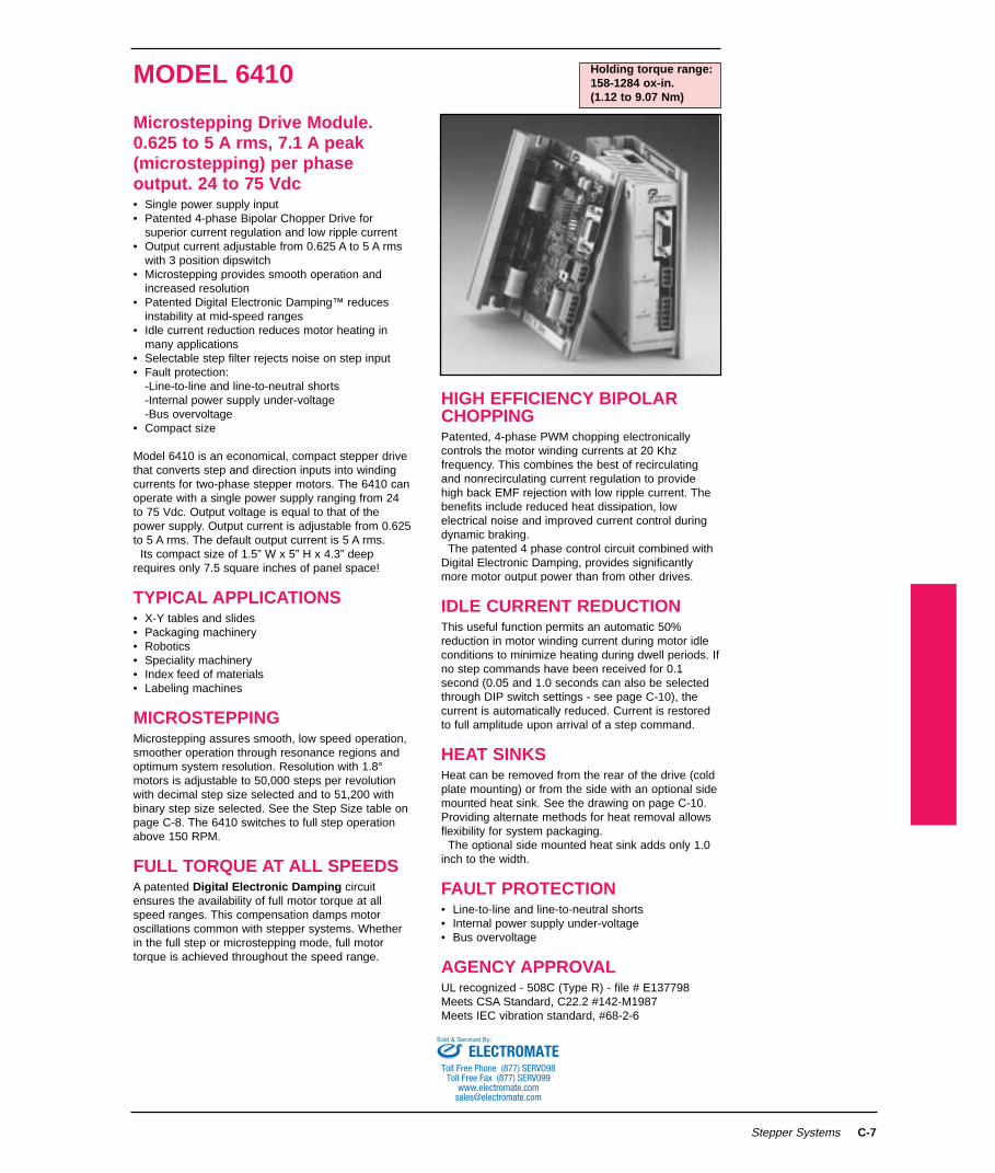
Model 6410 is an economical, compact stepper drivethat converts step and direction inputs into windingcurrents for two-phase stepper motors. The 6410 canoperate with a single power supply ranging from 24to 75 Vdc. Output voltage is equal to that of thepower supply. Output current is adjustable from 0.625to 5 A rms. The default output current is 5 A rms.

Its compact size of 1.5” W x 5” H x 4.3” deeprequires only 7.5 square inches of panel space!

TYPICAL APPLICATIONS• X-Y tables and slides• Packaging machinery• Robotics• Speciality machinery• Index feed of materials• Labeling machines

MICROSTEPPINGMicrostepping assures smooth, low speed operation,smoother operation through resonance regions andoptimum system resolution. Resolution with 1.8°motors is adjustable to 50,000 steps per revolutionwith decimal step size selected and to 51,200 withbinary step size selected. See the Step Size table onpage C-8. The 6410 switches to full step operationabove 150 RPM.

FULL TORQUE AT ALL SPEEDSA patented Digital Electronic Damping circuitensures the availability of full motor torque at allspeed ranges. This compensation damps motoroscillations common with stepper systems. Whetherin the full step or microstepping mode, full motortorque is achieved throughout the speed range.

HIGH EFFICIENCY BIPOLARCHOPPINGPatented, 4-phase PWM chopping electronicallycontrols the motor winding currents at 20 Khzfrequency. This combines the best of recirculatingand nonrecirculating current regulation to providehigh back EMF rejection with low ripple current. Thebenefits include reduced heat dissipation, lowelectrical noise and improved current control duringdynamic braking.

The patented 4 phase control circuit combined withDigital Electronic Damping, provides significantlymore motor output power than from other drives.

IDLE CURRENT REDUCTIONThis useful function permits an automatic 50%reduction in motor winding current during motor idleconditions to minimize heating during dwell periods. Ifno step commands have been received for 0.1second (0.05 and 1.0 seconds can also be selectedthrough DIP switch settings - see page C-10), thecurrent is automatically reduced. Current is restoredto full amplitude upon arrival of a step command.

HEAT SINKSHeat can be removed from the rear of the drive (coldplate mounting) or from the side with an optional sidemounted heat sink. See the drawing on page C-10.Providing alternate methods for heat removal allowsflexibility for system packaging.

The optional side mounted heat sink adds only 1.0inch to the width.

FAULT PROTECTION• Line-to-line and line-to-neutral shorts• Internal power supply under-voltage• Bus overvoltage

AGENCY APPROVALUL recognized - 508C (Type R) - file # E137798Meets CSA Standard, C22.2 #142-M1987Meets IEC vibration standard, #68-2-6

Holding torque range:158-1284 ox-in.(1.12 to 9.07 Nm)

ELECTROMATEToll Free Phone (877) SERVO98

Toll Free Fax (877) SERV099www.electromate.com

[email protected]

Sold & Serviced By:

C-8 Stepper Systems

Input Power Voltage . . . . . . . . . . . . . . .24 Vdc to 75 VdcInput Power Current . . . . . . . . . . . . . . .Motor and load dependent. Usually < motor phase current.Output motor phase current . . . . . . . . .See Figure C-4, page C-10

5 A rms max. (5 A peak full step, 7.1 A peak microstepping)Adjustable from 0.625 to 5 A rms in 0.625 amp increments

Inputs . . . . . . . . . . . . . . . . . . . . . . .See Figures C-2 and C-3, page C-9Step . . . . . . . . . . . . . . . . . . .Optically isolated TTL compatible

Minimum opto current (opto on): 5.5 maMaximum opto current (opto on): 10 maMinimum pulse width: 250 ns (1 µs when step filter enabled)Maximum frequency: 2.0 MHz (500 KHz when step filter enabled)Motion occurs on low-to-high transition of STEP input (J3 Pin 6)

Dir . . . . . . . . . . . . . . . . . . . .Optically isolated TTL compatibleFor normal motor connections:

Current in opto (opto on): RotationCCW looking at motor shaft

Minimum opto current (opto on): 3 maMaximum opto current (opto on): 4.5 maMinimum setup time: 50.0 µsMinimum hold time: zero

Enable . . . . . . . . . . . . . . . . .Optically isolated TTL compatibleSense of ENABLE input can be changed using ENBL_SENSE jumper:Jumper In: Current in opto (opto on) enables driveJumper Out: Current in opto (opto on) disables driveMinimum opto current (opto on): 3 maMaximum opto current (opto on): 4.5 ma

Outputs . . . . . . . . . . . . . . . . . . . . . . .See Figures C-2 and C-3, page C-9Enabled . . . . . . . . . . . . . . . .Optically isolated open collector, open emitter

Drive Enabled: opto transistor on, Vsat = 0.5 V max. @ 2.0 maDrive Disabled: opto transistor off, Vce max. = 35 V

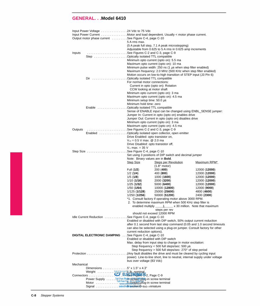
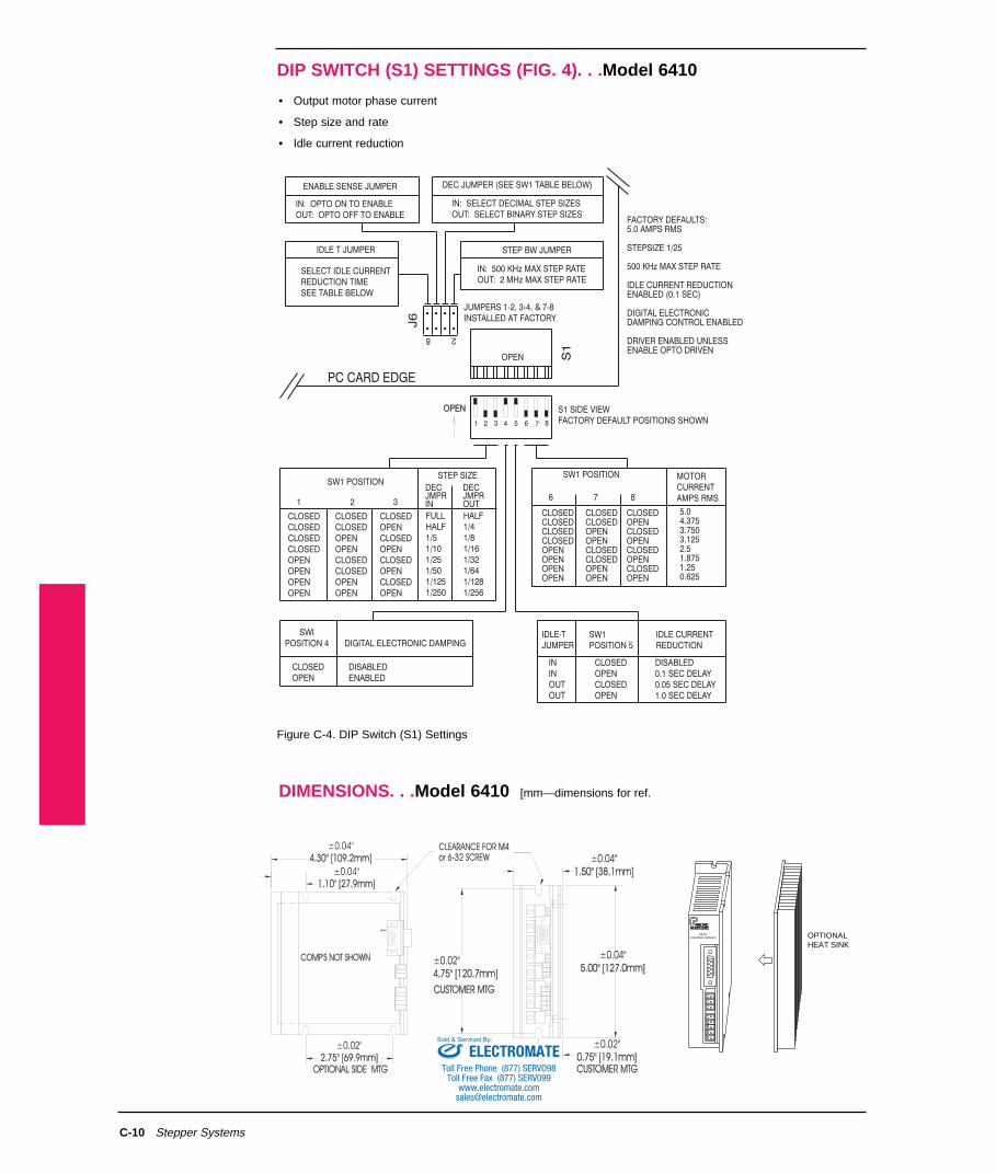
Step Size . . . . . . . . . . . . . . . . . . . . . . .See Figure C-4, page C-10Set using 3 positions of DIP switch and decimal jumper Note: Binary values are in Bold.Step Size Steps per Revolution Maximum RPM*

(1.8° motor)Full (1/2) 200 (400) 12000 (12000)1/2 (1/4) 400 (800) 12000 (12000)1/5 (1/8) 1000 (1600) 12000 (12000)1/10 (1/16) 2000 (3200) 12000 (12000)1/25 (1/32) 5000 (6400) 12000 (12000)1/50 (1/64) 10000 (12800) 12000 (9000)1/125 (1/128) 25000 (25600) 4800 (4600)1/250 (1/256) 50000 (51200) 2400 (2300)*1. Consult factory if operating motor above 3000 RPM.2. To determine maximum RPM when 500 KHz step filter is

enabled multiply 1 x 30 million. Note that maximum steps per rev

should not exceed 12000 RPMIdle Current Reduction . . . . . . . . . . . . .See Figure C-4, page C-10

Enabled or disabled with DIP switch, 50% output current reduction after 0.1 second from last step command (0.05 and 1.0 second timeoutscan also be selected using a plug-on jumper. Consult factory for othercurrent reduction options).

DIGITAL ELECTRONIC DAMPING . . .See Figure C-4, page C-10Enabled or disabled with DIP switchMax. delay from input step to change in motor excitation:

Step frequency < 500 full steps/sec: 500 µsStep frequency > 500 full steps/sec: 270° of step period

Protection . . . . . . . . . . . . . . . . . . . . . . .(Any fault disables the drive and must be cleared by cycling input power) Line-to-line short, line to neutral, internal supply under voltage bus over voltage (83 Vdc)

MechanicalDimensions . . . . . . . . . . . . . .5” x 1.5” x 4.3”Weight . . . . . . . . . . . . . . . . .1 lb. nominal

Connectors . . . . . . . . . . . . . . . . . . . . . .See Figure C-2, Page C-9Power Supply . . . . . . . . . . . .3 contact plug-in screw terminalMotor . . . . . . . . . . . . . . . . . .5 contact plug-in screw terminalSignal . . . . . . . . . . . . . . . . . .9 socket D-sub miniature

GENERAL. . .Model 6410

ELECTROMATEToll Free Phone (877) SERVO98

Toll Free Fax (877) SERV099www.electromate.com

[email protected]

Sold & Serviced By:

ENVIRONMENTAL . . . Model 6410

C-9

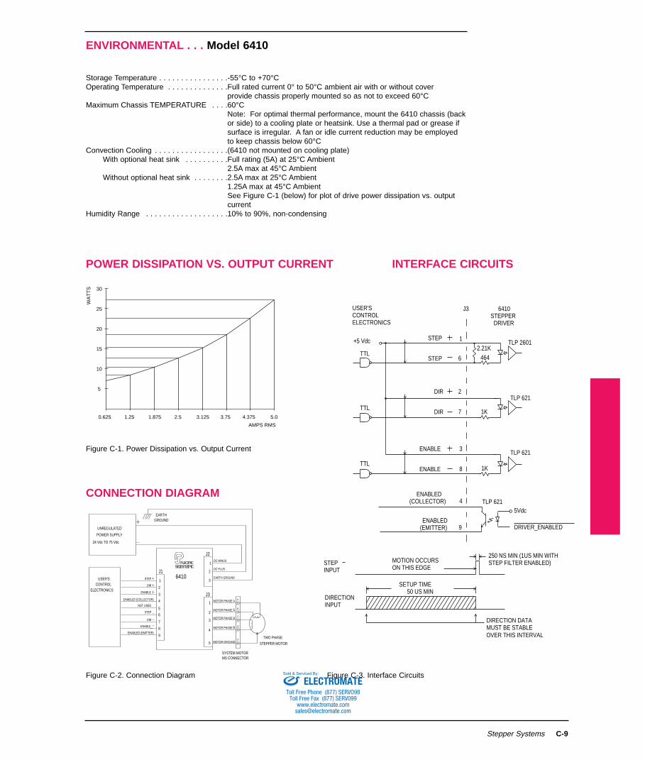
Storage Temperature . . . . . . . . . . . . . . . .-55°C to +70°COperating Temperature . . . . . . . . . . . . . .Full rated current 0° to 50°C ambient air with or without cover

provide chassis properly mounted so as not to exceed 60°CMaximum Chassis TEMPERATURE . . . .60°C

Note: For optimal thermal performance, mount the 6410 chassis (backor side) to a cooling plate or heatsink. Use a thermal pad or grease ifsurface is irregular. A fan or idle current reduction may be employedto keep chassis below 60°C

Convection Cooling . . . . . . . . . . . . . . . . .(6410 not mounted on cooling plate)With optional heat sink . . . . . . . . . .Full rating (5A) at 25°C Ambient

2.5A max at 45°C AmbientWithout optional heat sink . . . . . . . .2.5A max at 25°C Ambient

1.25A max at 45°C AmbientSee Figure C-1 (below) for plot of drive power dissipation vs. outputcurrent

Humidity Range . . . . . . . . . . . . . . . . . . .10% to 90%, non-condensing

Stepper Systems

POWER DISSIPATION VS. OUTPUT CURRENT INTERFACE CIRCUITS

0.625 1.25 1.875 2.5 3.125 3.75 4.375 5.0

AMPS RMS

5

10

15

20

25

30

WA

TT

S

TLP 621

TLP 2601

TLP 621

5Vdc

DRIVER_ENABLED

TTL

TTL

SETUP TIME

DIRECTION DATA

ENABLE

ENABLE

3

8

DIR

DIR

STEP

STEP 1

6

2

7

(COLLECTOR) 4

(EMITTER) 9

TTL

USER'SCONTROLELECTRONICS

+5 Vdc

STEPPERDRIVER

MOTION OCCURSON THIS EDGE

STEPINPUT

DIRECTIONINPUT

6410

ENABLED

ENABLED

J3

50 US MIN

OVER THIS INTERVALMUST BE STABLE

2.21K464

1K

1K

TLP 621

STEP FILTER ENABLED)250 NS MIN (1US MIN WITH

6410

GROUNDEARTH

24 Vdc TO 75 Vdc

POWER SUPPLY

UNREGULATED

9

ENABLE

DIR

STEP

NOT USED

ENABLE3

DIR

STEP 1

2

4

5

6

7

8

ENABLED (COLLECTOR)

ENABLED (EMITTER)

ELECTRONICSCONTROL

USER'S

DC MINUS

EARTH GROUND

DC PLUS

1

2

3

MOTOR PHASE A

SYSTEM MOTORMS CONNECTOR

MOTOR GROUNDTWO PHASE

STEPPER MOTOR

MOTOR PHASE A A

MOTOR PHASE B

MOTOR PHASE B

2

3

4

5

1

J2

J1

J3

B

E

C

D

CONNECTION DIAGRAM

Figure C-1. Power Dissipation vs. Output Current

Figure C-2. Connection Diagram Figure C-3. Interface CircuitsELECTROMATE

Toll Free Phone (877) SERVO98Toll Free Fax (877) SERV099

[email protected]

Sold & Serviced By:

DIP SWITCH (S1) SETTINGS (FIG. 4). . .Model 6410

C-10 Stepper Systems

• Output motor phase current

• Step size and rate

• Idle current reduction

OPENOPEN

SWIPOSITION 4

CLOSEDOPEN

DIGITAL ELECTRONIC DAMPING

DISABLEDENABLED

SW1 POSITION

1 2 3

STEP SIZE

CLOSEDCLOSEDCLOSEDCLOSEDOPENOPENOPENOPEN

CLOSEDCLOSEDOPENOPENCLOSEDCLOSEDOPENOPEN

CLOSEDOPENCLOSEDOPENCLOSEDOPENCLOSEDOPEN

DECJMPRIN

DECJMPROUT

FULLHALF1/51/101/251/501/1251/250

HALF1/41/81/161/321/641/1281/256

IN: OPTO ON TO ENABLEOUT: OPTO OFF TO ENABLE

ENABLE SENSE JUMPER

IDLE T JUMPER

SELECT IDLE CURRENTREDUCTION TIMESEE TABLE BELOW

DEC JUMPER (SEE SW1 TABLE BELOW)

IN: SELECT DECIMAL STEP SIZESOUT: SELECT BINARY STEP SIZES

STEP BW JUMPER

IN: 500 KHz MAX STEP RATEOUT: 2 MHz MAX STEP RATE

JUMPERS 1-2, 3-4, & 7-8INSTALLED AT FACTORY

OPEN

IDLE-TJUMPER

SW1POSITION 5

IDLE CURRENTREDUCTION

ININOUTOUT

CLOSEDOPENCLOSEDOPEN

DISABLED0.1 SEC DELAY0.05 SEC DELAY1.0 SEC DELAY

PC CARD EDGE

S1

J6

8 2

MOTORCURRENTAMPS RMS

SW1 POSITION

6 7 8

CLOSEDCLOSEDCLOSEDCLOSEDOPENOPENOPENOPEN

CLOSEDCLOSEDOPENOPENCLOSEDCLOSEDOPENOPEN

CLOSEDOPENCLOSEDOPENCLOSEDOPENCLOSEDOPEN

5.04.3753.7503.1252.51.8751.250.625

1 2 3 4 5 6 7 8

S1 SIDE VIEWFACTORY DEFAULT POSITIONS SHOWN

FACTORY DEFAULTS:5.0 AMPS RMS

STEPSIZE 1/25

500 KHz MAX STEP RATE

IDLE CURRENT REDUCTIONENABLED (0.1 SEC)

DIGITAL ELECTRONICDAMPING CONTROL ENABLED

DRIVER ENABLED UNLESSENABLE OPTO DRIVEN

Figure C-4. DIP Switch (S1) Settings

DIMENSIONS. . .Model 6410 [mm—dimensions for ref.

OPTIONALHEAT SINK

6410STEPPER DRIVER

ELECTROMATEToll Free Phone (877) SERVO98

Toll Free Fax (877) SERV099www.electromate.com

[email protected]

Sold & Serviced By:

FUNCTIONAL ENHANCEMENT

C-11

The 6410 microstepping drive is the core component utilized in a full family of products adding enhancedfunctionality.

ADDITIONAL PRODUCTS24-75 Vdc Input:

6415 Oscillator/Drive . . . . . . .± 0-10 Vdc input or on board potentiometers6420 Indexer/Drive . . . . . . . .RS232/RS485 programmable package, mnemonic language, 8 BDIO

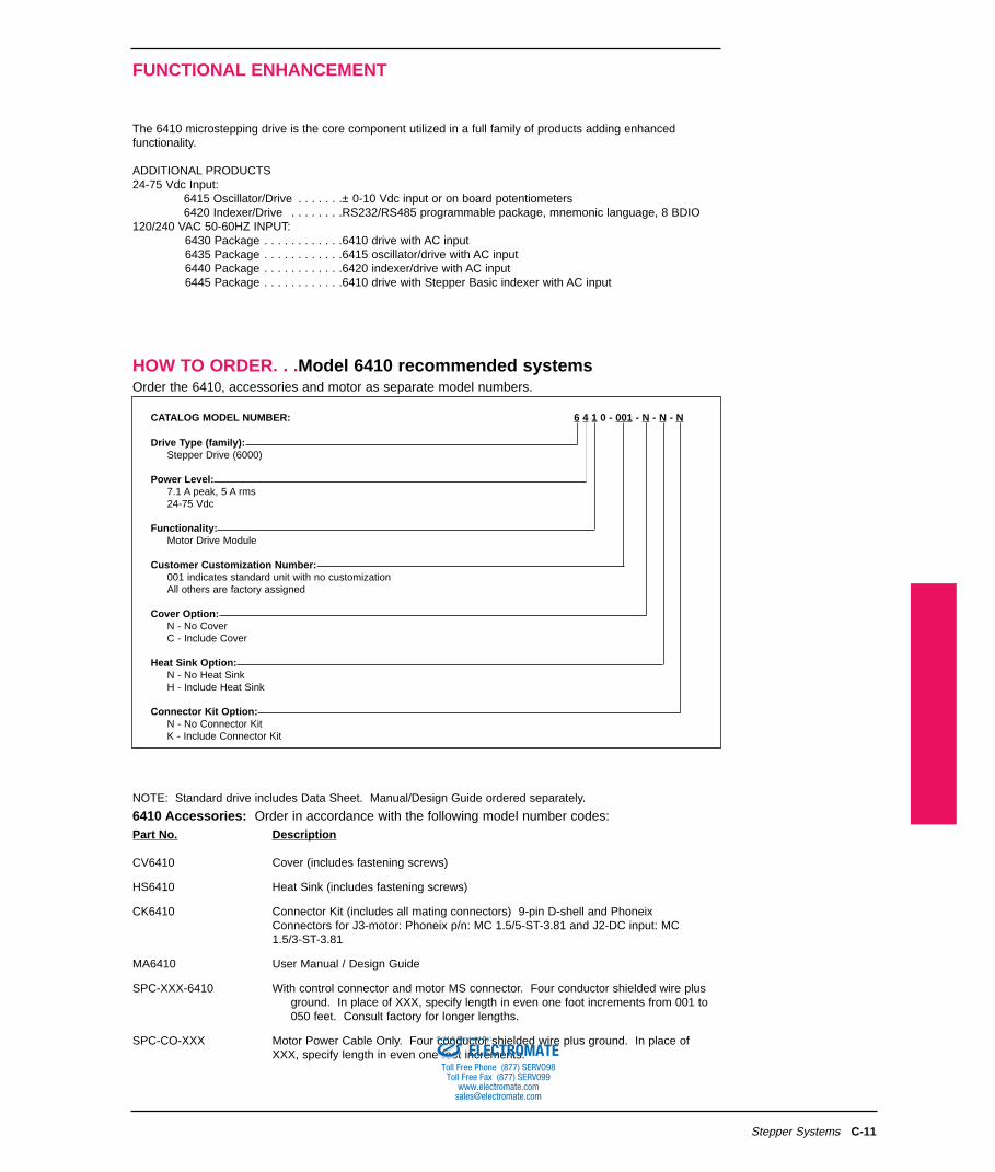
120/240 VAC 50-60HZ INPUT:6430 Package . . . . . . . . . . . .6410 drive with AC input6435 Package . . . . . . . . . . . .6415 oscillator/drive with AC input6440 Package . . . . . . . . . . . .6420 indexer/drive with AC input6445 Package . . . . . . . . . . . .6410 drive with Stepper Basic indexer with AC input

Stepper Systems

HOW TO ORDER. . .Model 6410 recommended systemsOrder the 6410, accessories and motor as separate model numbers.

CATALOG MODEL NUMBER: 6 4 1 0 - 001 - N - N - N

Drive Type (family):Stepper Drive (6000)

Power Level:7.1 A peak, 5 A rms24-75 Vdc

Functionality:Motor Drive Module

Customer Customization Number:001 indicates standard unit with no customizationAll others are factory assigned

Cover Option:N - No CoverC - Include Cover

Heat Sink Option:N - No Heat SinkH - Include Heat Sink

Connector Kit Option:N - No Connector KitK - Include Connector Kit

NOTE: Standard drive includes Data Sheet. Manual/Design Guide ordered separately.

6410 Accessories: Order in accordance with the following model number codes:Part No. Description

CV6410 Cover (includes fastening screws)

HS6410 Heat Sink (includes fastening screws)

CK6410 Connector Kit (includes all mating connectors) 9-pin D-shell and Phoneix Connectors for J3-motor: Phoneix p/n: MC 1.5/5-ST-3.81 and J2-DC input: MC 1.5/3-ST-3.81

MA6410 User Manual / Design Guide

SPC-XXX-6410 With control connector and motor MS connector. Four conductor shielded wire plus ground. In place of XXX, specify length in even one foot increments from 001 to 050 feet. Consult factory for longer lengths.

SPC-CO-XXX Motor Power Cable Only. Four conductor shielded wire plus ground. In place of XXX, specify length in even one foot increments.ELECTROMATE

Toll Free Phone (877) SERVO98Toll Free Fax (877) SERV099

[email protected]

Sold & Serviced By:

SYSTEM RATINGS AND CHARACTERISTICS

C-12 Stepper Systems

5.0 A,65V per phase

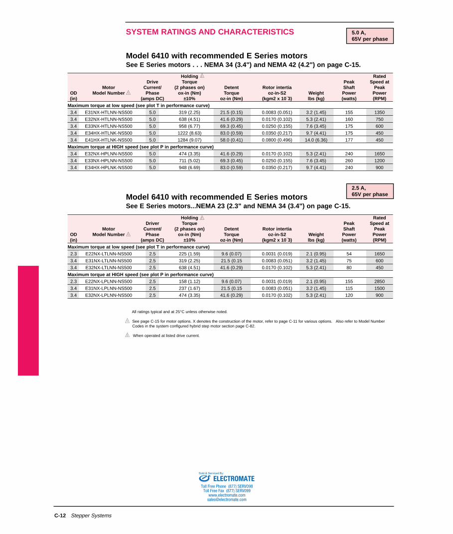
Model 6410 with recommended E Series motorsSee E Series motors . . . NEMA 34 (3.4") and NEMA 42 (4.2") on page C-15.

Model 6410 with recommended E Series motorsSee E Series motors...NEMA 23 (2.3" and NEMA 34 (3.4") on page C-15.

All ratings typical and at 25°C unless otherwise noted.

See page C-15 for motor options. X denotes the construction of the motor, refer to page C-11 for various options. Also refer to Model NumberCodes in the system configured hybrid step motor section page C-82.

When operated at listed drive current.

2.5 A,65V per phase

Holding RatedDrive Torque Peak Speed at

Motor Current/ (2 phases on) Detent Rotor intertia Shaft PeakOD Model Number Phase ox-in (Nm) Torque oz-in-S2 Weight Power Power(in) (amps DC) ±10% oz-in (Nm) (kgm2 x 10¯3) lbs (kg) (watts) (RPM)

Maximum torque at low speed (see plot T in performance curve)3.4 E31NX-HTLNN-NS500 5.0 319 (2.25) 21.5 (0.15) 0.0083 (0.051) 3.2 (1.45) 155 1350

3.4 E32NX-HTLNN-NS500 5.0 638 (4.51) 41.6 (0.29) 0.0170 (0.102) 5.3 (2.41) 160 750

3.4 E33NX-HTLNN-NS500 5.0 958 (6.77) 69.3 (0.45) 0.0250 (0.155) 7.6 (3.45) 175 600

3.4 E34HX-HTLNK-NS500 5.0 1222 (8.63) 83.0 (0.59) 0.0350 (0.217) 9.7 (4.41) 175 450

3.4 E41HX-HTLNK-NS500 5.0 1284 (9.07) 58.0 (0.41) 0.0800 (0.496) 14.0 (6.36) 177 450

Maximum torque at HIGH speed (see plot P in performance curve)3.4 E32NX-HPLNN-NS500 5.0 474 (3.35) 41.6 (0.29) 0.0170 (0.102) 5.3 (2.41) 240 1650

3.4 E33NX-HPLNN-NS500 5.0 711 (5.02) 69.3 (0.45) 0.0250 (0.155) 7.6 (3.45) 260 1200

3.4 E34HX-HPLNK-NS500 5.0 948 (6.69) 83.0 (0.59) 0.0350 (0.217) 9.7 (4.41) 240 900

Holding RatedDriver Torque Peak Speed at

Motor Current/ (2 phases on) Detent Rotor intertia Shaft PeakOD Model Number Phase ox-in (Nm) Torque oz-in-S2 Weight Power Power(in) (amps DC) ±10% oz-in (Nm) (kgm2 x 10¯3) lbs (kg) (watts) (RPM)

Maximum torque at low speed (see plot T in performance curve)2.3 E22NX-LTLNN-NS500 2.5 225 (1.59) 9.6 (0.07) 0.0031 (0.019) 2.1 (0.95) 54 1650

3.4 E31NX-LTLNN-NS500 2.5 319 (2.25) 21.5 (0.15 0.0083 (0.051) 3.2 (1.45) 75 600

3.4 E32NX-LTLNN-NS500 2.5 638 (4.51) 41.6 (0.29) 0.0170 (0.102) 5.3 (2.41) 80 450

Maximum torque at HIGH speed (see plot P in performance curve)2.3 E22NX-LPLNN-NS500 2.5 158 (1.12) 9.6 (0.07) 0.0031 (0.019) 2.1 (0.95) 155 2850

3.4 E31NX-LPLNN-NS500 2.5 237 (1.67) 21.5 (0.15 0.0083 (0.051) 3.2 (1.45) 115 1500

3.4 E32NX-LPLNN-NS500 2.5 474 (3.35) 41.6 (0.29) 0.0170 (0.102) 5.3 (2.41) 120 900

ELECTROMATEToll Free Phone (877) SERVO98

Toll Free Fax (877) SERV099www.electromate.com

[email protected]

Sold & Serviced By:

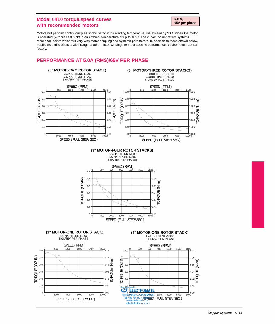
Model 6410 torque/speed curveswith recommended motors

C-13

Motors will perform continuously as shown without the winding temperature rise exceeding 90°C when the motoris operated (without heat sink) in an ambient temperature of up to 40°C. The curves do not reflect systemsresonance points which will vary with motor coupling and systems parameters. In addition to those shown below,Pacific Scientific offers a wide range of other motor windings to meet specific performance requirements. Consultfactory.

Stepper Systems

PERFORMANCE AT 5.0A (RMS)/65V PER PHASE

SPEED (RPM)

TOR

QU

E (O

Z-IN

)

0 1000 2000 3000 4000 5000 60000

200

400

600

800

1000

12000 300 600 900 1200 1500 1800

0.00

1.41

2.82

4.24

5.65

7.06

8.47

TOR

QU

E (N

-m)

(3" MOTOR-FOUR ROTOR STACKS)E34HX-HTLNK-NS00E32HX-HPLNK-NS005.0A/65V PER PHASE

SPEED (FULL STEP/SEC)

T

P

0 2000 4000 6000 8000 100000

100

200

300

400

500

6000 600 1200 1800 2400 3000

0.00

0.71

1.41

2.12

2.82

3.53

4.24

SPEED (RPM)

TOR

QU

E (O

Z-IN

)

TOR

QU

E (N

-m)

(3" MOTOR-TWO ROTOR STACK)E32NX-HTLNN-NS00E32NX-HPLNN-NS005.0A/65V PER PHASE

SPEED (FULL STEP/SEC)

T

P

TOR

QU

E (N

-m)

0 2000 4000 6000 8000 100000

150

300

450

600

750

9000 600 1200 1800 2400 3000

0.00

1.06

2.12

3.18

4.24

5.30

6.36

SPEED (RPM)

TOR

QU

E (O

Z-IN

)

(3" MOTOR-THREE ROTOR STACKS)E33NX-HTLNK-NS00E33NX-HPLNK-NS005.0A/65V PER PHASE

SPEED (FULL STEP/SEC)

T

P

0 2000 4000 6000 8000 100000

50

100

150

200

250

3000 600 1200 1800 2400 3000

0.00

0.35

0.71

1.06

1.41

1.77

2.12

SPEED(RPM)

TOR

QU

E (O

Z-IN

)

TOR

QU

E (N

-m)

(3" MOTOR-ONE ROTOR STACK)E31NX-HTLNN-NS005.0A/65V PER PHASE

T

SPEED (FULL STEP/SEC)0 1000 2000 3000 4000 5000 6000

0

200

400

600

800

1000

12000 300 600 900 1200 1500 1800

0.00

1.41

2.82

4.24

5.65

7.06

8.47

SPEED (RPM)

TOR

QU

E (O

Z-IN

)

TOR

QU

E (N

-m)

(4" MOTOR-ONE ROTOR STACK)E41HX-HTLNK-NS005.0A/65V PER PHASE

SPEED (FULL STEP/SEC)

T

5.0 A,65V per phase

ELECTROMATEToll Free Phone (877) SERVO98

Toll Free Fax (877) SERV099www.electromate.com

[email protected]

Sold & Serviced By:

C-14 Stepper Systems

2.5 A,65V per phase

PERFORMANCE AT 2.5A (RMS)/65V PER PHASE

SPEED (FULL STEP/SEC)0 2000 4000 6000 8000 10000

0

50

100

150

200

250

3000 600 1200 1800 2400 3000

0.00

0.35

0.71

1.06

1.41

1.77

2.12

SPEED(RPM)

TOR

QU

E (O

Z-IN

)

TOR

QU

E (N

-m)

(3" MOTOR-ONE ROTOR STACK)E31NX-LTLNN-NS00E31NX-LPLNN-NS00

2.5A/65V PER PHASE

T

P

SPEED (FULL STEP/SEC)0 2000 4000 6000 8000 10000

0

100

200

300

400

500

6000 600 1200 1800 2400 3000

0.00

0.71

1.41

2.12

2.83

3.53

4.24

SPEED (RPM)

TOR

QU

E (O

Z-IN

)

TOR

QU

E (N

-m)

(3" MOTOR-TWO ROTOR STACK)E32NX-LTLNN-NS00E32NX-LPLNN-NS00

2.5A/65V PER PHASE

T

P

0 2000 4000 6000 8000 100000

40

80

120

160

2000 600 1200 1800 2400 3000

0.00

0.28

0.56

0.85

1.13

1.41

SPEED (RPM)

TOR

QU

E (O

Z-IN

)

TOR

QU

E (N

-m)

(2" MOTOR-TWO ROTOR STACKS)E22NX-LTLNN-NS00E22NX-LPLNN-NS00

2.5A/65V PER PHASE

SPEED (FULL STEP/SEC)

T

P

ELECTROMATEToll Free Phone (877) SERVO98

Toll Free Fax (877) SERV099www.electromate.com

[email protected]

Sold & Serviced By:

C-15Stepper Systems

NEMA 23, 34 AND 42 MECHANICAL CONFIGURATIONS

REGULAR CONSTRUCTION/FLYING LEAD HOOK-UP

SPLASHPROOF CONSTRUCTION

SYSTEMS CONSTRUCTION

1

MAX.

.58

.76

.06

.06

1,52

(.18)

(4,57)1.25

31,75

Ø

5,54

5,51

8,53

3.38)

85,85)

4X Ø THRU

EQUALLY SPACED ON

A Ø B.C.

.2185,46

3 .875

98,43

2.875 ± .002

A0,077

.003

.003

0,077

73,025 ± 0,51

A

+.0000-.0005

9,53 - 0,013

.002

-A-

0,051

.3750

1 4 LEAD MOTORS: #18 AWG,

MINIMUM

6 & 8 LEAD MOTORS: #22 AWG,

MINIMUM

NOTE:

L MAX.

Ø

MOTOR LEADS

12.0304,8

12.0

304,8

+.0000-.0005 .3750

9,53 -0,013Ø

1.25

31,75

.06

1,52

(.18)(4,57)

(85,85)

(3.38)

4X Ø THRU

EQUALLY SPACED ON

A Ø B.C.

.218

5,46

3.875

98,43

.003A

0,077

2.875 ± .002

73.025 ± 0.051

.002

-A-0,051

.003

0,077 A

(43.69)

2.02

51.31MAX.

R(1.72)

Ø

(2X 45¡)

L2

L1 MAX.

REMOVABLEINSULATING BUSHING

1

(2.87)

(72,9)

(4.02)

(102,11)

(5 30)

3.62

91,95

4.77

121,16

6 05

31N (L OR M)

32N (L OR M)

MODELNUMBER L1 MAX. L2

+.0000-.0005 .3750

ENCODER OPTION ONLY

9,53 -0,013Ø

1.25

31,75

.06

1,52

(.18)(4,57)

.71

18,04

(85,85)

(3.38)

4X Ø THRU

EQUALLY SPACED ON A

Ø B.C.

.218

5,46

3.875

98,43

.003A

0,077

2.875 ± .002

73,025 ± 0,051

.002

-A-0,051

.003

0,077 A

(43,69)

2.62

66,55MAX.

R(1.72)

MAX-ENCODEROPTION ONLYØ

(2X 45˙)

L2

L1 MAX.

ENCODERCONNECTOR-

MOTOR CONNECTOR

MODEL

NUMBER

A

31NX 32NX 33NX

2.58

65,54

5.06

128,53

B

3.76

95,51

D

2HNX 21NX 22NX 33HX 34HX

1.56

39,63

2.06

52,33

3.06

77,73

5.33

135,39

6.58

162,14

1.25

31,75

0.81

20,57

0.81

20,57

1.25

31,75

0.81

20,57

0.25

6,35

0.25

6,35

0.25

6,35

0.375

9,53

1.25

31,75

0.375

9,53

0.375

9,53

1.25

31,75

0.5

12,7

1.25

31,75

0.5

12,7

Substitute R for X for flying lead

Note:

MODEL

NUMBER

A

33HX 34HX 41HX

6.73

170,94

5.61

142,5

B

7.62

193,55

D

31NX 32NX 33NX 42HX 43HX

3.62

91,95

4.77

121,16

6.05

153,67

8.04

204,22

10.56

268,23

1.125

31,75

1.125

31,75

1.125

31,75

1.125

31,75

1.125

31,75

0.375

9,53

0.375

9,53

0.375

9,53

0.5

12.7

1.75

44,45

0.625

15,875

0.5

12.7

2.19

55,63

0.625

15,875

2.19

55,63

0.75

19,05

Substitute L for X to specifyconduit connection (1/2 NPS Tap)

Substitute M for X to specifyconduit connection (PDG 11 Tap)

Note:

A

B

D

33HX 34HX 41HX

6.73

170,94

5.61

142,5

7.62

193,55

31NX 32NX 33NX 42HX 43HX

3.62

91,95

4.77

121,16

6.05

153,67

8.04

204,22

10.56

268,23

1.125

31,75

1.125

31,75

1.125

31,75

1.125

31,75

1.125

31,75

0.375

9,53

0.375

9,53

0.375

9,53

0.5

12.7

1.75

44,45

0.625

15,875

0.5

12.7

2.19

55,63

0.625

15,875

2.19

55,63

0.75

19,05

MODEL

NUMBER Note:

Substitute C for X for MS connectortermination

ELECTROMATEToll Free Phone (877) SERVO98

Toll Free Fax (877) SERV099www.electromate.com

[email protected]

Sold & Serviced By:

MODEL 6415

C-16

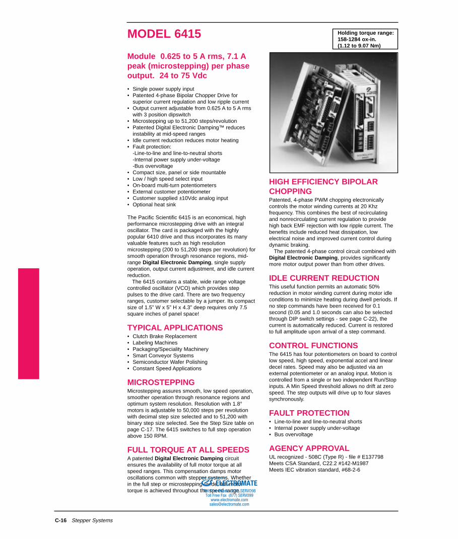
Module 0.625 to 5 A rms, 7.1 Apeak (microstepping) per phaseoutput. 24 to 75 Vdc

• Single power supply input • Patented 4-phase Bipolar Chopper Drive for

superior current regulation and low ripple current• Output current adjustable from 0.625 A to 5 A rms

with 3 position dipswitch• Microstepping up to 51,200 steps/revolution• Patented Digital Electronic Damping™ reduces

instability at mid-speed ranges• Idle current reduction reduces motor heating• Fault protection:

-Line-to-line and line-to-neutral shorts-Internal power supply under-voltage-Bus overvoltage

• Compact size, panel or side mountable• Low / high speed select input• On-board multi-turn potentiometers • External customer potentiometer• Customer supplied ±10Vdc analog input• Optional heat sink

The Pacific Scientific 6415 is an economical, highperformance microstepping drive with an integraloscillator. The card is packaged with the highlypopular 6410 drive and thus incorporates its manyvaluable features such as high resolutionmicrostepping (200 to 51,200 steps per revolution) forsmooth operation through resonance regions, mid-range Digital Electronic Damping, single supplyoperation, output current adjustment, and idle currentreduction.

The 6415 contains a stable, wide range voltagecontrolled oscillator (VCO) which provides steppulses to the drive card. There are two frequencyranges, customer selectable by a jumper. Its compactsize of 1.5” W x 5” H x 4.3” deep requires only 7.5square inches of panel space!

TYPICAL APPLICATIONS• Clutch Brake Replacement• Labeling Machines• Packaging/Speciality Machinery• Smart Conveyor Systems• Semiconductor Wafer Polishing• Constant Speed Applications

MICROSTEPPINGMicrostepping assures smooth, low speed operation,smoother operation through resonance regions andoptimum system resolution. Resolution with 1.8°motors is adjustable to 50,000 steps per revolutionwith decimal step size selected and to 51,200 withbinary step size selected. See the Step Size table onpage C-17. The 6415 switches to full step operationabove 150 RPM.

FULL TORQUE AT ALL SPEEDSA patented Digital Electronic Damping circuitensures the availability of full motor torque at allspeed ranges. This compensation damps motoroscillations common with stepper systems. Whetherin the full step or microstepping mode, full motortorque is achieved throughout the speed range.

Stepper Systems

HIGH EFFICIENCY BIPOLARCHOPPINGPatented, 4-phase PWM chopping electronicallycontrols the motor winding currents at 20 Khzfrequency. This combines the best of recirculatingand nonrecirculating current regulation to providehigh back EMF rejection with low ripple current. Thebenefits include reduced heat dissipation, lowelectrical noise and improved current control duringdynamic braking.

The patented 4-phase control circuit combined withDigital Electronic Damping, provides significantlymore motor output power than from other drives.

IDLE CURRENT REDUCTIONThis useful function permits an automatic 50%reduction in motor winding current during motor idleconditions to minimize heating during dwell periods. Ifno step commands have been received for 0.1second (0.05 and 1.0 seconds can also be selectedthrough DIP switch settings - see page C-22), thecurrent is automatically reduced. Current is restoredto full amplitude upon arrival of a step command.

CONTROL FUNCTIONSThe 6415 has four potentiometers on board to controllow speed, high speed, exponential accel and lineardecel rates. Speed may also be adjusted via anexternal potentiometer or an analog input. Motion iscontrolled from a single or two independent Run/Stopinputs. A Min Speed threshold allows no drift at zerospeed. The step outputs will drive up to four slavessynchronously.

FAULT PROTECTION• Line-to-line and line-to-neutral shorts• Internal power supply under-voltage• Bus overvoltage

AGENCY APPROVALUL recognized - 508C (Type R) - file # E137798Meets CSA Standard, C22.2 #142-M1987Meets IEC vibration standard, #68-2-6

Holding torque range:158-1284 ox-in.(1.12 to 9.07 Nm)

ELECTROMATEToll Free Phone (877) SERVO98

Toll Free Fax (877) SERV099www.electromate.com

[email protected]

Sold & Serviced By:

GENERAL. . .Model 6415

C-17

Input Power Voltage . . . . . . . . . . . . . . .24 Vdc to 75 VdcInput Power Current . . . . . . . . . . . . . . .Motor and load dependent. Usually < motor phase current.Output motor phase current . . . . . . . . .See Figure C-15, page C-22

5 A rms max. (5 A peak full step, 7.1 A peak microstepping)Adjustable from 0.625 to 5 A rms in 0.625 amp increments

Run Speed Control . . . . . . . . . . . . . . . .Analog input range. See Figures C-10 and C-11, page C-21Also controllable with internal or external pots ±10 Vdc

Analog Input Impedance . . . .20 KW (differential amp)High Frequency Range . . . . .Run Speed Control: 8 KHZ to 500 KHZ

Low Speed Control: 8 KHz to 370 KHzLow Frequency Range . . . . .Run Speed Control: 4 KHz to 250 KHz

Low Speed Control: 4 KHz to 180 KHz

Run Speed/Low SpeedStability Over Temp./Range . .±1% of full scale (typical)

Accel Ramp . . . . . . . . . . . . . . . . . . . . .ExponentialAccel Pot Fully CW: 0.4 sec (single time constant)Accel Pot Fully CCW: 0.4 msec (single time constant)

Decel Ramp . . . . . . . . . . . . . . . . . . . . .LinearDecel Pot Fully CW: 1.4 secDecel Pot Fully CCW: 6.0 msec

Min Speed . . . . . . . . . . . . . . . . . . . . . .4 KHz maximum (high frequency range)2 KHz maximum (low frequency range)Steps below this frequency are inhibited to insure no movement at endof decel ramp. This functionality can be disabled by inserting jumper E5Note: Motor rpm = 0.3 * Freq. (Hz)/step size.For example: If frequency = 500 KHz and step size = 125, rpm = 1200.

Inputs . . . . . . . . . . . . . . . . . . . . . . .Optically isolated TTL compatibleSee Figures C-8 and C-9, page C-20

OutputsVCO Input Monitor . . . . . . . .100 KW input impedance

8 Vdc full scale+8 V Ref. Out . . . . . . . . . . . .50 ma max. @ 25 deg C ambient

25 ma max. @ 50 deg C ambientStep Out . . . . . . . . . . . . . . . .See Figure C-9, page C-20

100 ma max. @ 25 deg C ambient50 ma max. @ 50 deg C ambient(max reverse voltage = -50 Vdc)

Step Size . . . . . . . . . . . . . . . . . . . . . . .See Figure C-15, page C-22Set using 3 positions of DIP switch and decimal jumper Note: Binary values are in BoldStep Size Steps per Revolution Maximum RPM*

(1.8° motor)Full (1/2) 200 (400) 12000 (12000)1/2 (1/4) 400 (800) 12000 (12000)1/5 (1/8) 1000 (1600) 12000 (12000)1/10 (1/16) 2000 (3200) 12000 (12000)1/25 (1/32) 5000 (6400) 12000 (12000)1/50 (1/64) 10000 (12800) 12000 (9000)1/125 (1/128) 25000 (25600) 4800 (4600)1/250 (1/256) 50000 (51200) 2400 (2300)*1. Consult factory if operating motor above 3000 RPM.

Idle Current Reduction . . . . . . . . . . . . .See Figure C-15, page C-22Enabled or disabled with DIP switch, 50% output current reduction after0.1 second from last step command (0.05 and 1.0 second time-outs canalso be selected using a plug-on jumper. Consult factory for othercurrent reduction options).

DIGITAL ELECTRONIC DAMPING . . .See Figure C-15, page C-22Enabled or disabled with DIP switchMax. delay from input step to change in motor excitation:

Step frequency < 500 full steps/sec: 500 µsStep frequency > 500 full steps/sec: 270° of step period

Protection . . . . . . . . . . . . . . . . . . . . . . .(Any fault disables the drive and must be cleared by cycling input power) Line-to-line short, line to neutral, internal supply under voltage bus over voltage (83 Vdc)

MechanicalDimensions . . . . . . . . . . . . . .5” x 1.5” x 4.3”Weight . . . . . . . . . . . . . . . . .1 lb. nominal

Stepper Systems

ELECTROMATEToll Free Phone (877) SERVO98

Toll Free Fax (877) SERV099www.electromate.com

[email protected]

Sold & Serviced By:

GENERAL AND ENVIRONMENTAL. . .Model 6415

C-18

Connectors . . . . . . . . . . . . . . . . . . . . . .See Figure C-7, page C-19Power Supply . . . . . . . . . . . .3 contact plug-in screw terminalMotor . . . . . . . . . . . . . . . . . .5 contact plug-in screw terminalSignal . . . . . . . . . . . . . . . . . .25 contact plug D sub miniature

Storage Temperature . . . . . . . . . . . . . .-55°C to +70°COperating Temperature . . . . . . . . . . . . .Full rated current 0° to 50°C ambient air with or without cover

provided chassis properly mounted so as not to exceed 60°C.Maximum Chassis Temperature . . . . . .60°C.

Note: For optimal thermal performance, mount the 6415 chassis (back or side) to a cooling plate or heatsink. Use a thermal pad orgrease if surface is irregular. A fan or idle current reduction may be employed to keep chassis below 60°C

Convection Cooling . . . . . . . . . . . . . . .(6415 not mounted on cooling plate)With optional heat sink . . . . .Full rating (5A) at 25°C Ambient

2.5A max at 45°C AmbientWithout optional heat sink . . .2.5A max at 25°C Ambient

1.25A max at 45°C AmbientSee chart below for plot of drive power dissipation vs. outputcurrent.

Humidity Range . . . . . . . . . . . . . . . . . .10% to 90%, non-condensing

Stepper Systems

DRIVE POWER DISSIPATIONCHART

DIMENSIONS. . .Model 6415 [mm—dimensions for ref. only]

OPTIONALOPTIONALHEAT SINKHEAT SINK

1.0" [2.5mm]

6415 OSCILLATOR

DRIVER

BB

BB

AA

AA

++

LED 1

Figure C-5.

ELECTROMATEToll Free Phone (877) SERVO98

Toll Free Fax (877) SERV099www.electromate.com

[email protected]

Sold & Serviced By:

DIMENSIONS. . .Model 6415 [mm—dimensions for ref. only]

C-19Stepper Systems

1

2

3

14

15

16

4

17

5

18

6

19

7

8

21

9

22

10

23

11

24

12

25

13

20

VCO_INPUT_MON

+8V_REF_OUT

+8V_REF_OUT

+8V_REF_OUT

EXTERNAL_POT

GNDA

GNDA

GNDA

GNDA

ANALOG_INPUT+

ANALOG_INPUT-

LOW_SPD+

LOW_SPD-

RUN+

RUN-

STOP+

STOP-

DIR+

DIR-

ENABLE+

ENABLE-

STEP_OUT

STEP_OUT

STEP_OUT

STEP_OUT

Use

r's C

ontr

olE

lect

roni

cs

J4

1

2

3

4

5

6

7

8

9

NOT USED

5

4

3

2

1

1

2

3

J3

J2DC-

DC+

Case GND

Unregulated24Vdc to 75Vdc

2 PhaseStepperMotor

Phase A

Phase A

Phase B

Phase B

Case GND

J1

6415OSCILLATOR

DRIVE

CONNECTION DIAGRAM. . .Model 6415

M4x8mmM4x8mm

M4x8mmM4x8mm

CUSTOMER MTG

M4x8mmM4x8mmM4x8mmM4x8mm

M4x8mmM4x8mm M4x8mmM4x8mm

4.75" [120.7mm]

OPTIONAL SIDE MTG

CLEARANCE FOR M4 or 6-32 SCREW

B

B

A

A

ACCEL RAMP

RUN SPEED

LOW SPEED

DECEL RAMP

++

6415 OSCILLATOR

DRIVER

2.75" [69.9 mm]

4.30" [109.2 mm]

1.50" [38.1 mm]

5.00" [127.0 mm]

+ 0.04"

CUSTOMER MTG

0.75" [19.1 mm]

+ 0.02"

+ 0.02"

+ 0.04"

1.10" [27.9 mm]

+ 0.04"

+ 0.02"

+ 0.04"

1.44" [36.7mm]

LED 1

Figure C-6.

Figure C-7. Connection Diagram ELECTROMATEToll Free Phone (877) SERVO98

Toll Free Fax (877) SERV099www.electromate.com

[email protected]

Sold & Serviced By:

DIGITAL INTERFACE CIRCUITRY. . .Model 6415

C-20

Run+/Run-, Stop+/Stop-,Separate Latched Inputs (E4 Jumper Installed-Default)

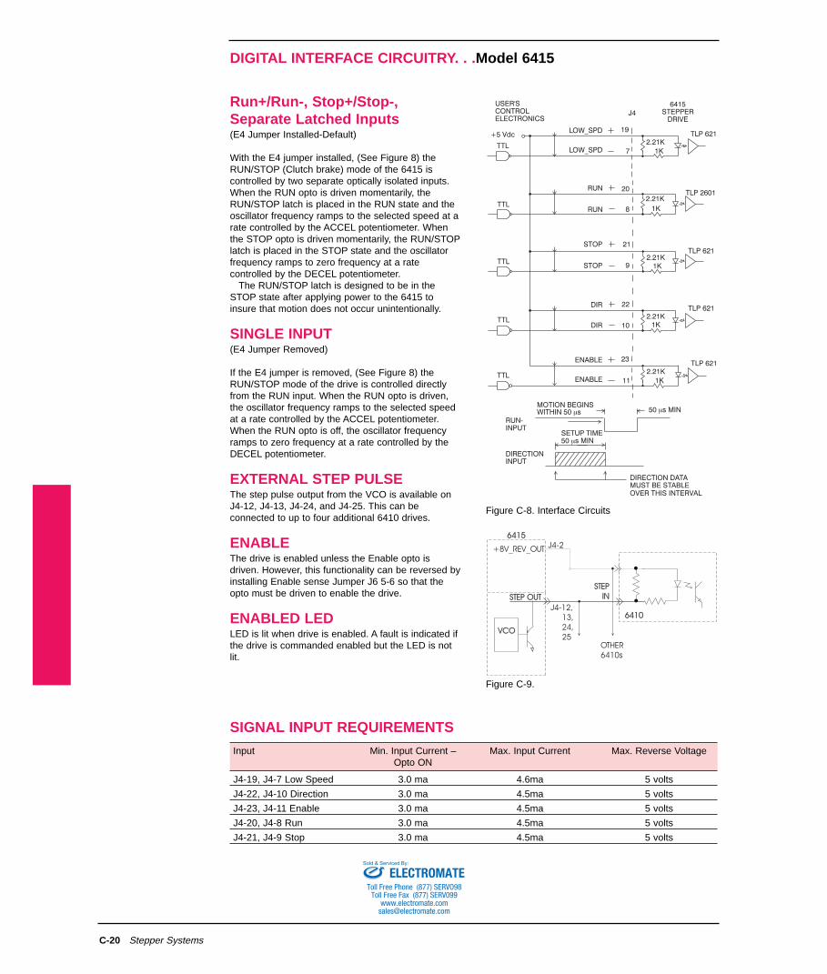
With the E4 jumper installed, (See Figure 8) theRUN/STOP (Clutch brake) mode of the 6415 iscontrolled by two separate optically isolated inputs.When the RUN opto is driven momentarily, theRUN/STOP latch is placed in the RUN state and theoscillator frequency ramps to the selected speed at arate controlled by the ACCEL potentiometer. Whenthe STOP opto is driven momentarily, the RUN/STOPlatch is placed in the STOP state and the oscillatorfrequency ramps to zero frequency at a ratecontrolled by the DECEL potentiometer.

The RUN/STOP latch is designed to be in theSTOP state after applying power to the 6415 toinsure that motion does not occur unintentionally.

SINGLE INPUT (E4 Jumper Removed)

If the E4 jumper is removed, (See Figure 8) theRUN/STOP mode of the drive is controlled directlyfrom the RUN input. When the RUN opto is driven,the oscillator frequency ramps to the selected speedat a rate controlled by the ACCEL potentiometer.When the RUN opto is off, the oscillator frequencyramps to zero frequency at a rate controlled by theDECEL potentiometer.

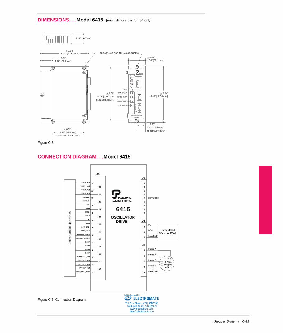
EXTERNAL STEP PULSEThe step pulse output from the VCO is available onJ4-12, J4-13, J4-24, and J4-25. This can beconnected to up to four additional 6410 drives.

ENABLEThe drive is enabled unless the Enable opto isdriven. However, this functionality can be reversed byinstalling Enable sense Jumper J6 5-6 so that theopto must be driven to enable the drive.

ENABLED LEDLED is lit when drive is enabled. A fault is indicated ifthe drive is commanded enabled but the LED is notlit.

Stepper Systems

TLP 2601

DIR

DIR

22

10

STOP

STOP

RUN

RUN 20

8

21

9

23

11

TTL

TTL

TTL

TTL

USER'SCONTROLELECTRONICS

+5 Vdc

STEPPERDRIVE

6415

ENABLE

ENABLE

J4

2.21K

2.21K

2.21K

2.21K

1K

1K

TLP 621

TLP 621

TLP 621

1K

1K

19

7TTL

LOW_SPD

LOW_SPD2.21K

TLP 621

1K

MOTION BEGINSWITHIN 50 sm

SETUP TIME

RUN-INPUT

DIRECTIONINPUT

DIRECTION DATA

50 s MINm

OVER THIS INTERVALMUST BE STABLE

50 s MINm

STEP

IN

STEP

IN

VCOVCO

+8V_REV_OUT

OTHER

6410s

64106410J4-12,

13,

24,

25

64156415

STEP OUTSTEP OUT

J4-2

SIGNAL INPUT REQUIREMENTS

Figure C-8. Interface Circuits

Figure C-9.

Input Min. Input Current – Max. Input Current Max. Reverse VoltageOpto ON

J4-19, J4-7 Low Speed 3.0 ma 4.6ma 5 volts

J4-22, J4-10 Direction 3.0 ma 4.5ma 5 volts

J4-23, J4-11 Enable 3.0 ma 4.5ma 5 volts

J4-20, J4-8 Run 3.0 ma 4.5ma 5 volts

J4-21, J4-9 Stop 3.0 ma 4.5ma 5 volts

ELECTROMATEToll Free Phone (877) SERVO98

Toll Free Fax (877) SERV099www.electromate.com

[email protected]

Sold & Serviced By:

ANALOG INTERFACE CIRCUITRY. . .Model 6415

C-21

LOW_SPD+/LOW_SPD-This optically isolated input selects the source of theanalog speed command. With the LOW_SPD optoon (J4-7 Low), the analog speed command is derivedfrom the LOW SPEED potentiometer.

With the LOW_SPD opto off (J4-7 High), theanalog speed command is derived from one of thefollowing sources depending upon the E1 and E3jumper configurations:

• Internal RUN SPEED potentiometer (E1 1-2 and E3 1-2 installed - Default)

• External potentiometer (E1 3-4 installed)• External analog input (E1 5-6 and E3 1-2

installed)• External analog input scaled (fine tuned) by

internal RUN SPEED potentiometer (E1 1-2 and E3 3-4 installed)

The LOW_SPD input can change at any time. Thespeed (oscillator frequency) will not change instantly,but will ramp to the newly selected speed at a ratecontrolled by the ACCEL or DECEL potentiometersdepending upon whether the speed (magnitude) isincreasing or decreasing.

Figure C-12 shows the velocity wave form in atypical application where the high speed is selectedwhen the RUN input is pulsed and latched. Near theend of the motion profile, low speed is selected toinsure a short and precise stopping distance whenthe STOP input is pulsed.

Adjustment PotentiometersFigures C-12 and C-13 show the typical velocity(pulse frequency) profile in response to a separateRUN/STOP or with a single RUN/STOP andRUN/LOW commands.

Adjustments for RUN SPEED, LOW SPEED,ACCEL RAMP, and DECEL RAMP are made with 4multi-turn potentiometers.

LOW SPEED is typically set lower than RUNSPEED to allow for accurate stopping. It can also beused as a second RUN SPEED. ACCEL RAMP istypically set to minimize time to reach RUN SPEEDwithout allowing the motor to stall. The DECELRAMP is linear and stable, allowing a more precise,repeatable stopping position.

Stepper Systems

J4 6415

USER'SPOT

15

3

16

10K

+8V_REF_OUT

GND A

EXTERNAL POT(Z > 1 MEG OHM)in

USER'SSIGNALSOURCE

6

18

ANALOG_INPUT-

ANALOG_INPUT+

10K

10K 10K

10K

16.2K

16.2K

0.01UF

0.01UF

J4 6415

Figure C-10.

Figure C-11.

Figure C-12.

Figure C-13.

ELECTROMATEToll Free Phone (877) SERVO98

Toll Free Fax (877) SERV099www.electromate.com

[email protected]

Sold & Serviced By:

C-22 Stepper Systems

DIP SWITCH (S1) SETTINGS. . .Model 6415

SW1JMPR

Side View 6415

Oscillator Board

E2 - Frequency Range

INOUT

LOW FREQUENCYHIGH FREQUENCY

E5 - MIN SPEED Frequency

INOUT

DISABLEDENABLED

E4 - RUN/STOP Control

INOUT

SEPARATE INPUTSSINGLE INPUT

E1 E3 - Velocity Control Mode

1-2 IN

3-4 IN

5-6 IN

1-2 IN

1-2 IN

N/A

1-2 IN

3-4 IN

Internal RUN SPEEDPotentiometerExternal Potentiometer

External Analog Input

External Analog Inputscaled by internalRUN SPEED potentiometer

LED1LED1

RU

NS

PE

ED

RU

NS

PE

ED

LOW

SP

EE

DLO

WS

PE

ED

AC

CE

LR

AM

PA

CC

EL

RA

MP

DE

CE

LR

AM

PD

EC

EL

RA

MP

E3E3

11 1166

E1E1

U13U13

E8E8 E7E7

E6E6

E5E5

E4E4

U16U16U3U3

U14U14

U10U10

U12U12

U1U1U2U2

U7U7 U8U8

U15U15

E2E2 U9U9

J4J4

11

14142525

Control SourceDIR+/DIR-

Jumpers

Analog In

E6OUTOUTIN

ININ

OUT

E7OUTOUTIN

OUTOUT

OUT

E8OUTOUTOUT

ININ

OUT

DIR OptoDrivenNot DrivenDrivenNot DrivenDrivenNot Driven

Analog In-----------------------------NegativePositive

RotationCCWCWCCWCWCCWCW

OPENOPEN

SWIPOSITION 4

CLOSEDOPEN

DIGITAL ELECTRONIC DAMPING

DISABLEDENABLED

SW1 POSITION

1 2 3

STEP SIZE

CLOSEDCLOSEDCLOSEDCLOSEDOPENOPENOPENOPEN

CLOSEDCLOSEDOPENOPENCLOSEDCLOSEDOPENOPEN

CLOSEDOPENCLOSEDOPENCLOSEDOPENCLOSEDOPEN

DECJMPRIN

DECJMPROUT

FULLHALF1/51/101/251/501/1251/250

HALF1/41/81/161/321/641/1281/256

IN: OPTO ON TO ENABLEOUT: OPTO OFF TO ENABLE

ENABLE SENSE JUMPER

IDLE T JUMPER

SELECT IDLE CURRENTREDUCTION TIMESEE TABLE BELOW

DEC JUMPER (SEE SW1 TABLE BELOW)

IN: SELECT DECIMAL STEP SIZESOUT: SELECT BINARY STEP SIZES

STEP BW JUMPER

IN: 500 KHz MAX STEP RATEOUT: 2 MHz MAX STEP RATE

JUMPERS 1-2, 3-4, & 7-8INSTALLED AT FACTORY

OPEN

IDLE-TJUMPER

SW1POSITION 5

IDLE CURRENTREDUCTION

ININOUTOUT

CLOSEDOPENCLOSEDOPEN

DISABLED0.1 SEC DELAY0.05 SEC DELAY1.0 SEC DELAY

PC CARD EDGE

S1

J6

8 2

MOTORCURRENTAMPS RMS

SW1 POSITION

6 7 8

CLOSEDCLOSEDCLOSEDCLOSEDOPENOPENOPENOPEN

CLOSEDCLOSEDOPENOPENCLOSEDCLOSEDOPENOPEN

CLOSEDOPENCLOSEDOPENCLOSEDOPENCLOSEDOPEN

5.04.3753.7503.1252.51.8751.250.625

1 2 3 4 5 6 7 8

S1 SIDE VIEWFACTORY DEFAULT POSITIONS SHOWN

FACTORY DEFAULTS:5.0 AMPS RMS

STEPSIZE 1/25

500 KHz MAX STEP RATE

IDLE CURRENT REDUCTIONENABLED (0.1 SEC)

DIGITAL ELECTRONICDAMPING CONTROL ENABLED

DRIVER ENABLED UNLESSENABLE OPTO DRIVEN

OSCILLATOR LOWER BOARD

Figure C-14.

Figure C-15.

OSCILLATOR UPPER BOARD [factory defaults are in bold]

ELECTROMATEToll Free Phone (877) SERVO98

Toll Free Fax (877) SERV099www.electromate.com

[email protected]

Sold & Serviced By:

C-23Stepper Systems

FUNCTIONAL ENHANCEMENT

The 6415 microstepping oscillator drive is one of a full family of products adding enhanced functionality.

Additional Products24-75 Vdc Input:

6410 Step Motor Drive . . . . . .Step and direction input drive6420 Indexer/Drive . . . . . . . .RS232/RS485 programmable package mnemonic language 8 BDIO

120/240 Vac 50-60Hz Input:6430 Package . . . . . . . . . . . .6410 drive with AC input6435 Package . . . . . . . . . . . .6415 oscillator/drive with AC input6440 Package . . . . . . . . . . . .6420 indexer/drive with AC input6445 Package . . . . . . . . . . . .6410 drive with Stepper Basic indexer and AC input functionality.

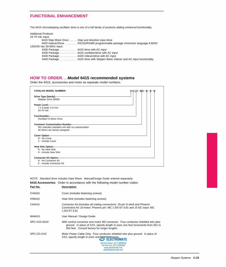
HOW TO ORDER. . .Model 6415 recommended systemsOrder the 6415, accessories and motor as separate model numbers.

CATALOG MODEL NUMBER: 6 4 1 5 - 001 - N - N - N

Drive Type (family):Stepper Drive (6000)

Power Level:7.1 A peak, 5 A rms24-75 Vdc

Functionality:Oscillator & Motor Drive

Customer Customization Number:001 indicates standard unit with no customizationAll others are factory assigned

Cover Option:N - No CoverC - Include Cover

Heat Sink Option:N - No Heat SinkH - Include Heat Sink

Connector Kit Option:N - No Connector KitK - Include Connector Kit

NOTE: Standard drive includes Data Sheet. Manual/Design Guide ordered separately.

6415 Accessories: Order in accordance with the following model number codes:Part No. Description

CV6415 Cover (includes fastening screws)

HS6410 Heat Sink (includes fastening screws)

CK6415 Connector Kit (includes all mating connectors) 25-pin D-shell and PhoenixConnectors for J3-motor: Phoenix p/n: MC 1.5/5-ST-3.81 and J2-DC input: MC 1.5/3-ST-3.81

MA6415 User Manual / Design Guide

SPC-XXX-6410 With control connector and motor MS connector. Four conductor shielded wire plus ground. In place of XXX, specify length in even one foot increments from 001 to 050 feet. Consult factory for longer lengths.

SPC-CO-XXX Motor Power Cable Only. Four conductor shielded wire plus ground. In place of XXX, specify length in even one foot increments.

ELECTROMATEToll Free Phone (877) SERVO98

Toll Free Fax (877) SERV099www.electromate.com

[email protected]

Sold & Serviced By:

C-24 Stepper Systems

SYSTEM RATINGS AND CHARACTERISTICS

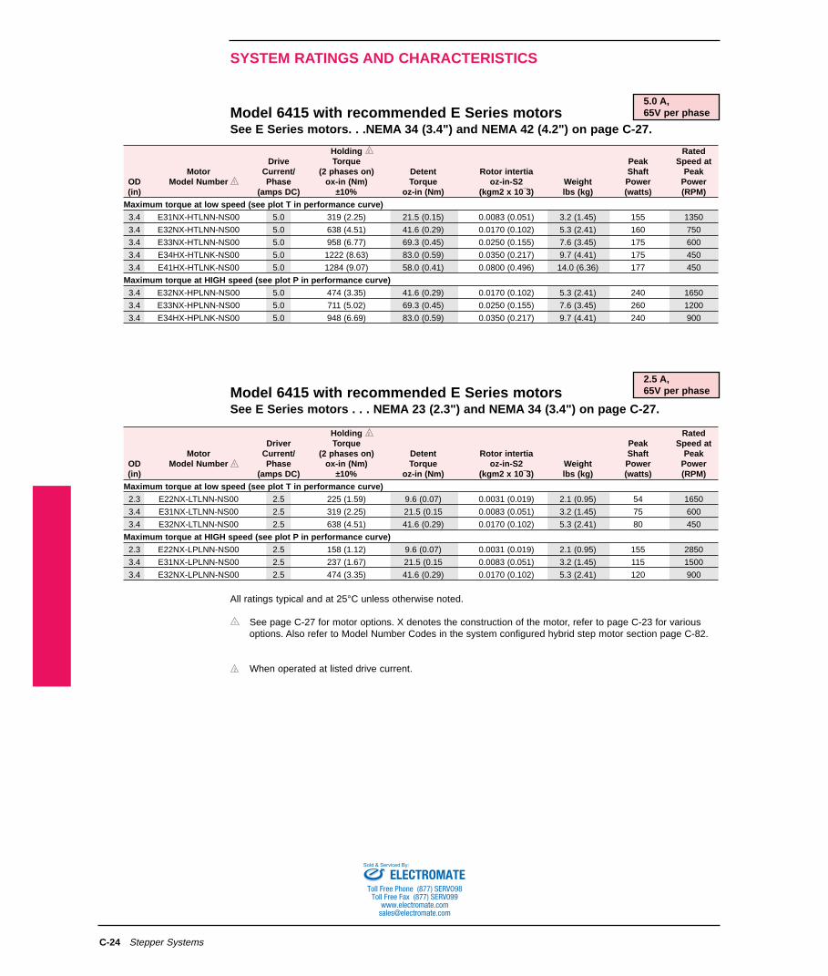
Model 6415 with recommended E Series motorsSee E Series motors. . .NEMA 34 (3.4") and NEMA 42 (4.2") on page C-27.

5.0 A,65V per phase

Model 6415 with recommended E Series motorsSee E Series motors . . . NEMA 23 (2.3") and NEMA 34 (3.4") on page C-27.

2.5 A,65V per phase

All ratings typical and at 25°C unless otherwise noted.

See page C-27 for motor options. X denotes the construction of the motor, refer to page C-23 for various options. Also refer to Model Number Codes in the system configured hybrid step motor section page C-82.

When operated at listed drive current.

Holding RatedDrive Torque Peak Speed at

Motor Current/ (2 phases on) Detent Rotor intertia Shaft PeakOD Model Number Phase ox-in (Nm) Torque oz-in-S2 Weight Power Power(in) (amps DC) ±10% oz-in (Nm) (kgm2 x 10¯3) lbs (kg) (watts) (RPM)

Maximum torque at low speed (see plot T in performance curve)3.4 E31NX-HTLNN-NS00 5.0 319 (2.25) 21.5 (0.15) 0.0083 (0.051) 3.2 (1.45) 155 1350

3.4 E32NX-HTLNN-NS00 5.0 638 (4.51) 41.6 (0.29) 0.0170 (0.102) 5.3 (2.41) 160 750

3.4 E33NX-HTLNN-NS00 5.0 958 (6.77) 69.3 (0.45) 0.0250 (0.155) 7.6 (3.45) 175 600

3.4 E34HX-HTLNK-NS00 5.0 1222 (8.63) 83.0 (0.59) 0.0350 (0.217) 9.7 (4.41) 175 450

3.4 E41HX-HTLNK-NS00 5.0 1284 (9.07) 58.0 (0.41) 0.0800 (0.496) 14.0 (6.36) 177 450

Maximum torque at HIGH speed (see plot P in performance curve)3.4 E32NX-HPLNN-NS00 5.0 474 (3.35) 41.6 (0.29) 0.0170 (0.102) 5.3 (2.41) 240 1650

3.4 E33NX-HPLNN-NS00 5.0 711 (5.02) 69.3 (0.45) 0.0250 (0.155) 7.6 (3.45) 260 1200

3.4 E34HX-HPLNK-NS00 5.0 948 (6.69) 83.0 (0.59) 0.0350 (0.217) 9.7 (4.41) 240 900

Holding RatedDriver Torque Peak Speed at

Motor Current/ (2 phases on) Detent Rotor intertia Shaft PeakOD Model Number Phase ox-in (Nm) Torque oz-in-S2 Weight Power Power(in) (amps DC) ±10% oz-in (Nm) (kgm2 x 10¯3) lbs (kg) (watts) (RPM)

Maximum torque at low speed (see plot T in performance curve)2.3 E22NX-LTLNN-NS00 2.5 225 (1.59) 9.6 (0.07) 0.0031 (0.019) 2.1 (0.95) 54 1650

3.4 E31NX-LTLNN-NS00 2.5 319 (2.25) 21.5 (0.15 0.0083 (0.051) 3.2 (1.45) 75 600

3.4 E32NX-LTLNN-NS00 2.5 638 (4.51) 41.6 (0.29) 0.0170 (0.102) 5.3 (2.41) 80 450

Maximum torque at HIGH speed (see plot P in performance curve)2.3 E22NX-LPLNN-NS00 2.5 158 (1.12) 9.6 (0.07) 0.0031 (0.019) 2.1 (0.95) 155 2850

3.4 E31NX-LPLNN-NS00 2.5 237 (1.67) 21.5 (0.15 0.0083 (0.051) 3.2 (1.45) 115 1500

3.4 E32NX-LPLNN-NS00 2.5 474 (3.35) 41.6 (0.29) 0.0170 (0.102) 5.3 (2.41) 120 900

ELECTROMATEToll Free Phone (877) SERVO98

Toll Free Fax (877) SERV099www.electromate.com

[email protected]

Sold & Serviced By:

C-25Stepper Systems

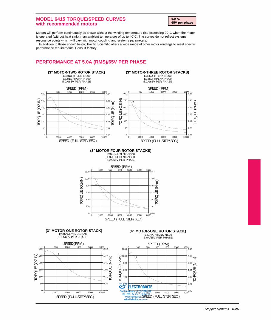
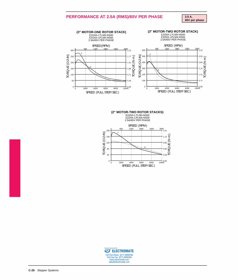
MODEL 6415 TORQUE/SPEED CURVESwith recommended motors

Motors will perform continuously as shown without the winding temperature rise exceeding 90°C when the motoris operated (without heat sink) in an ambient temperature of up to 40°C. The curves do not reflect systemsresonance points which will vary with motor coupling and systems parameters.

In addition to those shown below, Pacific Scientific offers a wide range of other motor windings to meet specificperformance requirements. Consult factory.

PERFORMANCE AT 5.0A (RMS)/65V PER PHASE

5.0 A,65V per phase

SPEED (RPM)

TOR

QU

E (O

Z-IN

)

0 1000 2000 3000 4000 5000 60000

200

400

600

800

1000

12000 300 600 900 1200 1500 1800

0.00

1.41

2.82

4.24

5.65

7.06

8.47

TOR

QU

E (N

-m)

(3" MOTOR-FOUR ROTOR STACKS)E34HX-HTLNK-NS00E32HX-HPLNK-NS005.0A/65V PER PHASE

SPEED (FULL STEP/SEC)

T

P

0 2000 4000 6000 8000 100000

100

200

300

400

500

6000 600 1200 1800 2400 3000

0.00

0.71

1.41

2.12

2.82

3.53

4.24

SPEED (RPM)

TOR

QU

E (O

Z-IN

)

TOR

QU

E (N

-m)

(3" MOTOR-TWO ROTOR STACK)E32NX-HTLNN-NS00E32NX-HPLNN-NS005.0A/65V PER PHASE

SPEED (FULL STEP/SEC)

T

P

TOR

QU

E (N

-m)

0 2000 4000 6000 8000 100000

150

300

450

600

750

9000 600 1200 1800 2400 3000

0.00

1.06

2.12

3.18

4.24

5.30

6.36

SPEED (RPM)

TOR

QU

E (O

Z-IN

)

(3" MOTOR-THREE ROTOR STACKS)E33NX-HTLNK-NS00E33NX-HPLNK-NS005.0A/65V PER PHASE

SPEED (FULL STEP/SEC)

T

P

0 2000 4000 6000 8000 100000

50

100

150

200

250

3000 600 1200 1800 2400 3000

0.00

0.35

0.71

1.06

1.41

1.77

2.12

SPEED(RPM)

TOR

QU

E (O

Z-IN

)

TOR

QU

E (N

-m)

(3" MOTOR-ONE ROTOR STACK)E31NX-HTLNN-NS005.0A/65V PER PHASE

T

SPEED (FULL STEP/SEC)0 1000 2000 3000 4000 5000 6000

0

200

400

600

800

1000

12000 300 600 900 1200 1500 1800

0.00

1.41

2.82

4.24

5.65

7.06

8.47

SPEED (RPM)

TOR

QU

E (O

Z-IN

)

TOR

QU

E (N

-m)

(4" MOTOR-ONE ROTOR STACK)E41HX-HTLNK-NS005.0A/65V PER PHASE

SPEED (FULL STEP/SEC)

T

ELECTROMATEToll Free Phone (877) SERVO98

Toll Free Fax (877) SERV099www.electromate.com

[email protected]

Sold & Serviced By:

C-26 Stepper Systems

PERFORMANCE AT 2.5A (RMS)/65V PER PHASE 2.5 A,65V per phase

SPEED (FULL STEP/SEC)0 2000 4000 6000 8000 10000

0

50

100

150

200

250

3000 600 1200 1800 2400 3000

0.00

0.35

0.71

1.06

1.41

1.77

2.12

SPEED(RPM)

TOR

QU

E (O

Z-IN

)

TOR

QU

E (N

-m)

(3" MOTOR-ONE ROTOR STACK)E31NX-LTLNN-NS00E31NX-LPLNN-NS00

2.5A/65V PER PHASE

T

P

SPEED (FULL STEP/SEC)0 2000 4000 6000 8000 10000

0

100

200

300

400

500

6000 600 1200 1800 2400 3000

0.00

0.71

1.41

2.12

2.83

3.53

4.24

SPEED (RPM)

TOR

QU

E (O

Z-IN

)

TOR

QU

E (N

-m)

(3" MOTOR-TWO ROTOR STACK)E32NX-LTLNN-NS00E32NX-LPLNN-NS00

2.5A/65V PER PHASE

T

P

0 2000 4000 6000 8000 100000

40

80

120

160

2000 600 1200 1800 2400 3000

0.00

0.28

0.56

0.85

1.13

1.41

SPEED (RPM)

TOR

QU

E (O

Z-IN

)

TOR

QU

E (N

-m)

(2" MOTOR-TWO ROTOR STACKS)E22NX-LTLNN-NS00E22NX-LPLNN-NS00

2.5A/65V PER PHASE

SPEED (FULL STEP/SEC)

T

P

ELECTROMATEToll Free Phone (877) SERVO98

Toll Free Fax (877) SERV099www.electromate.com

[email protected]

Sold & Serviced By:

C-27Stepper Systems

NEMA 23, 34 AND 42 MECHANICAL CONFIGURATIONS

REGULAR CONSTRUCTION/FLYING LEAD HOOK-UP

SPLASHPROOF CONSTRUCTION

SYSTEMS CONSTRUCTION

1

.06

1,52

(.18)

(4,57)1 25

Ø

38)

5,85)

4X Ø THRU

EQUALLY SPACED ON

A Ø B.C.

.2185,46

3 .875

98,43

2.875 ± .002

003

73,025 ± 0,51

+.0000-.0005

9,53 - 0,013

.002

-A-

0,051

.3750

1 4 LEAD MOTORS: #18 AWG,

MINIMUM

NOTE:

Ø

MOTOR LEADS

12.0304 8

+.0000-.0005 .3750

9,53 -0,013Ø

.06

1,52

( 18)

(85,85)

(3.38)

4X Ø THRU

EQUALLY SPACED ON

A Ø B.C.

.218

5,46

3.875

98,43

2.875 ± .002

73 025 0 051

.002

-A-0,051

(43.69)R

(1.72)

Ø

(2X 45¡)

+.0000-.0005 .3750

9,53 -0,013Ø

.06

1,52

(.18)(4,57)

.71

18,04

(85,85)

(3.38)

4X Ø THRU

EQUALLY SPACED ON A

Ø B.C.

.218

5,46

3.875

98,43

003

2.875 ± .002

73,025 ± 0,051

.002

-A-0,051

(43,69)

2.6

66,5

R(1.72)

MAX-ENCODEROPTION ONLYØ

(2X 45˙)

MODEL

NUMBER

A

31NX 32NX 33NX

2.58

65,54

5.06

128,53

B

3.76

95,51

D

2HNX 21NX 22NX 33HX 34HX

1.56

39,63

2.06

52,33

3.06

77,73

5.33

135,39

6.58

162,14

1.25

31,75

0.81

20,57

0.81

20,57

1.25

31,75

0.81

20,57

0.25

6,35

0.25

6,35

0.25

6,35

0.375

9,53

1.25

31,75

0.375

9,53

0.375

9,53

1.25

31,75

0.5

12,7

1.25

31,75

0.5

12,7

Substitute R for X for flying lead

Note:

MODEL

NUMBER

A

33HX 34HX 41HX

6.73

170,94

5.61

142,5

B

7.62

193,55

D

31NX 32NX 33NX 42HX 43HX

3.62

91,95

4.77

121,16

6.05

153,67

8.04

204,22

10.56

268,23

1.125

31,75

1.125

31,75

1.125

31,75

1.125

31,75

1.125

31,75

0.375

9,53

0.375

9,53

0.375

9,53

0.5

12.7

1.75

44,45

0.625

15,875

0.5

12.7

2.19

55,63

0.625

15,875

2.19

55,63

0.75

19,05

Substitute L for X to specifyconduit connection (1/2 NPS Tap)

Substitute M for X to specifyconduit connection (PDG 11 Tap)

Note:

A

B

D

33HX 34HX 41HX

6.73

170,94

5.61

142,5

7.62

193,55

31NX 32NX 33NX 42HX 43HX

3.62

91,95

4.77

121,16

6.05

153,67

8.04

204,22

10.56

268,23

1.125

31,75

1.125

31,75

1.125

31,75

1.125

31,75

1.125

31,75

0.375

9,53

0.375

9,53

0.375

9,53

0.5

12.7

1.75

44,45

0.625

15,875

0.5

12.7

2.19

55,63

0.625

15,875

2.19

55,63

0.75

19,05

MODEL

NUMBER Note:

Substitute C for X for MS connectortermination

ELECTROMATEToll Free Phone (877) SERVO98

Toll Free Fax (877) SERV099www.electromate.com

[email protected]

Sold & Serviced By:


Recommended