KLM Technology Group Practical Engineerin g Guidelines for Processing Plant SolutionsSOLUTIONS, STANDARDS AND SOFTWARE www.klmtechgroup.com Page : 1 of 58 Rev: 04 Rev 01 Jan 2007 Rev 02 May 2012 Rev 03 Sept 2012 Rev 04 Nov 2013 KLM Technology Group #03-12 Block Aronia, Jalan Sri Perkasa 2 Taman Tampoi Utama 81200 Johor Bahru MalaysiaKolmetz Handbook of Process Equipment Design Piping Hydraulics Fluid Flow Line Sizing and Material Selection (ENGINEERING DESIGN GUIDELINE) Co Author Rev 01 Ling Ai Li Rev 02 K Kolmetz Rev 03 Aprilia Jaya Rev 04 Aprilia Jaya Editor / Author Karl Kolmetz TABLE OF CONTENT INTRODUCTION Scope5 General Design Consideration6 DEFINITIONS 9NOMENCLATURE 11 THEORY OF THE DESIGN A) General Fluid Flow Theory 13 KLM Technology Group has developed; 1) Process Engineering Equipment Design Guidelines, 2) Equipment Design Software, 3) Project Engineering Standards and Spec ifications, and 4) Unit Operations Manuals. Each ha s many hours of engineering development. KLM is providing the introduction to this guideline for free on the internet. Please go to our website to order the complete document. www.klmtechgroup.com
Transcript
8102019 Kolmetz Handbook of Process Equipment Design
Rev 01 Jan 2007Rev 02 May 2012Rev 03 Sept 2012Rev 04 Nov 2013
KLM Technology Group03-12 Block AroniaJalan Sri Perkasa 2Taman Tampoi Utama81200 Johor BahruMalaysia
Kolmetz Handbookof Process Equipment Design
Piping Hydraulics Fluid FlowLine Sizing and
Material Selection
(ENGINEERING DESIGN GUIDELINE)
Co Author
Rev 01 Ling Ai LiRev 02 K KolmetzRev 03 Aprilia JayaRev 04 Aprilia Jaya
Editor Author
Karl Kolmetz
TABLE OF CONTENT
INTRODUCTION
Scope 5
General Design Consideration 6
DEFINITIONS 9
NOMENCLATURE 11
THEORY OF THE DESIGN
A) General Fluid Flow Theory 13
KLM Technology Group has developed 1) Process Engineering EquipmentDesign Guidelines 2) Equipment Design Software 3) Project EngineeringStandards and Specifications and 4) Unit Operations Manuals Each hasmany hours of engineering development
KLM is providing the introduction to this guideline for free on the internetPlease go to our website to order the complete document
wwwklmtechgroupcom
8102019 Kolmetz Handbook of Process Equipment Design
Practical EngineeringGuidelines for Processing Plant
Solutions
Kolmetz Handbookof Process Equipment Design
Piping Hydraulics Fluid FlowLine Sizing and
Material Selection
(ENGINEERING DESIGN GUIDELINES)
Page 2 of 58
Rev 04
November 2013
These design guideline are believed to be as accurate as possible but are very general and not for specific designcases They were designed for engineers to do preliminary designs and process specification sheets The finaldesign must always be guaranteed for the service selected by the manufacturing vendor but these guidelines willgreatly reduce the amount of up front engineering hours that are required to develop the final design The guidelinesare a training tool for young engineers or a resource for engineers with experience
This document is entrusted to the recipient personally but the copyright remains with us It must not be copied
reproduced or in any way communicated or made accessible to third parties without our written consent
I) Physical Properties of Fluids 13
Viscosity 13
Density Specific Volume and Specify Gravity 13
Mean Velocity 14
II) Flow Characteristic in Pipe 15
Reynolds Number 15
Fluid Flow Equations for the Friction LossPressure Drop in Pipe 16
Straight Line Pressure Drop 19
Effect of Valve Fitting on Pressure Drop 20
Enlargements and Contraction Pipe Line Pressure Drops Calculation 23
Nozzles and Orifices 24
Water Hammer 24
B) Piping Fluid Flow Material Selection 24
C) Line Sizing 28
I) Liquid Flow (In-Compressible Flow) 29
II) Gas Flow (Compressible Flow) 30
D) Pump Suction Piping 35
8102019 Kolmetz Handbook of Process Equipment Design
Practical EngineeringGuidelines for Processing Plant
Solutions
Kolmetz Handbookof Process Equipment Design
Piping Hydraulics Fluid FlowLine Sizing and
Material Selection
(ENGINEERING DESIGN GUIDELINES)
Page 3 of 58
Rev 04
November 2013
These design guideline are believed to be as accurate as possible but are very general and not for specific designcases They were designed for engineers to do preliminary designs and process specification sheets The finaldesign must always be guaranteed for the service selected by the manufacturing vendor but these guidelines willgreatly reduce the amount of up front engineering hours that are required to develop the final design The guidelinesare a training tool for young engineers or a resource for engineers with experience
This document is entrusted to the recipient personally but the copyright remains with us It must not be copied
reproduced or in any way communicated or made accessible to third parties without our written consent
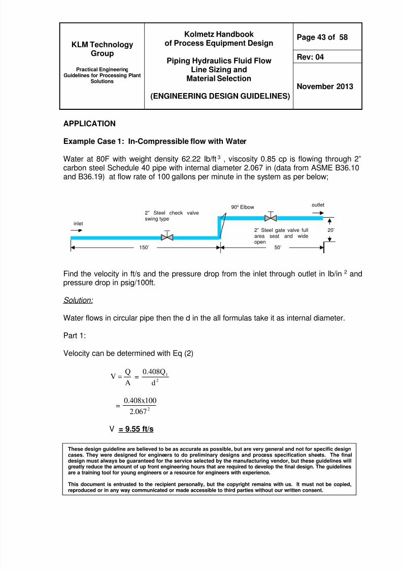
APPLICATION
Example Case 1 In-Compressible flow with Water 43
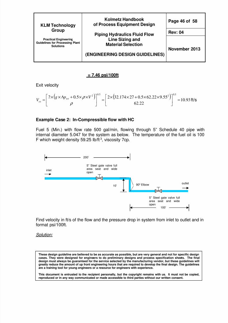
Example Case 2 In-Compressible flow with HC 46
Example Case 3 Compressible flow with Steam 49
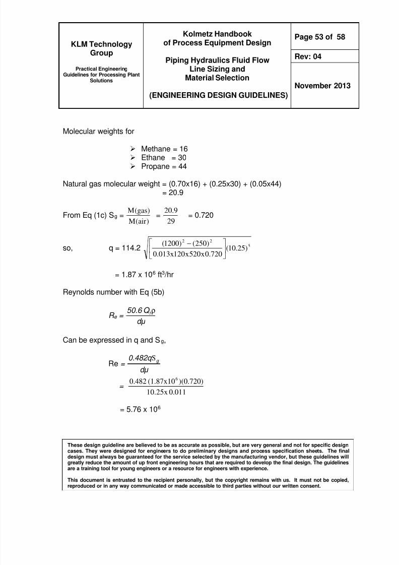
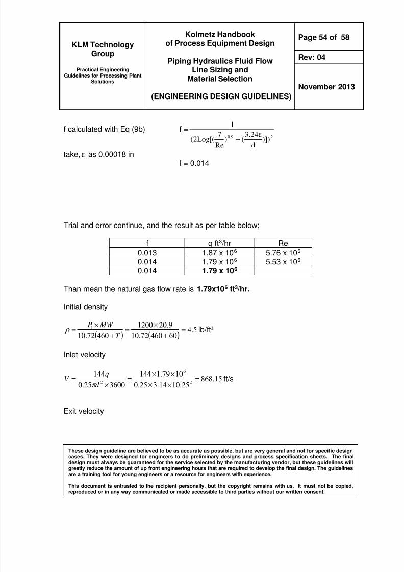
Example Case 4 Compressible flow with Natural Gas 52
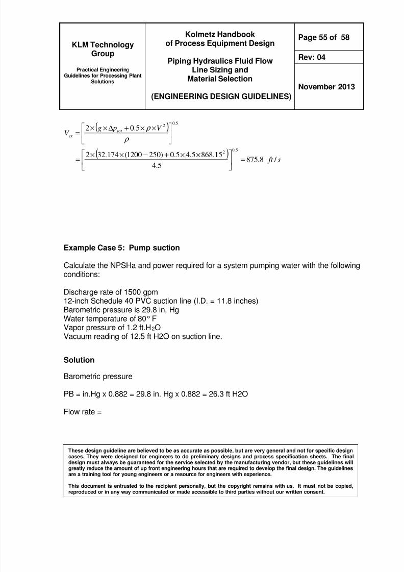
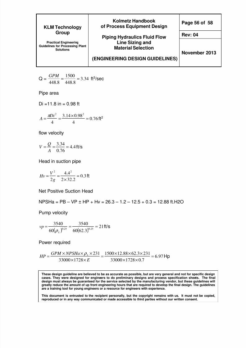
Example Case 5 Pump Suction 55
REFEREENCES 58
LIST OF TABLE
Table 1 General Pipe Material Roughness 19
Table 2a Example of the equivalent lengths for various kinds of fittings 21
Table 2b Friction factor for the commercial steel pipe 21
Table 3 Guideline for the Piping Fitting and Pipe Material Selection 29
Table 4 Pipe velocities and allowable pressure drops for various fluids 31
Table 5 Optimum velocity for various fluid densities 31
Table 6 Reasonable Velocities for flow of waterfluid with almost same densitythrough pipe 33
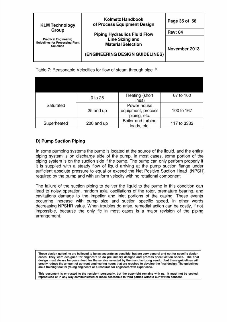
Table 7 Reasonable Velocities for flow of steam through pipe 37
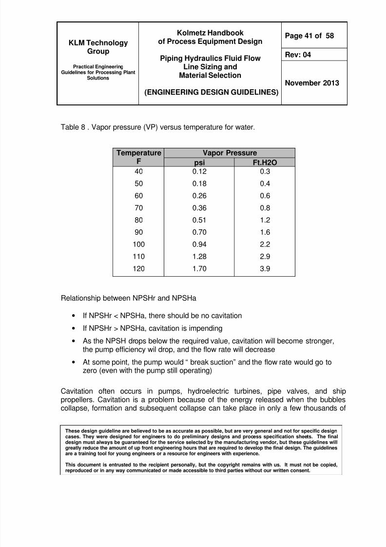
Table 8 Vapor pressure (VP) versus temperature for water 40
8102019 Kolmetz Handbook of Process Equipment Design
Practical EngineeringGuidelines for Processing Plant
Solutions
Kolmetz Handbookof Process Equipment Design
Piping Hydraulics Fluid FlowLine Sizing and
Material Selection
(ENGINEERING DESIGN GUIDELINES)
Page 4 of 58
Rev 04
November 2013
These design guideline are believed to be as accurate as possible but are very general and not for specific designcases They were designed for engineers to do preliminary designs and process specification sheets The finaldesign must always be guaranteed for the service selected by the manufacturing vendor but these guidelines willgreatly reduce the amount of up front engineering hours that are required to develop the final design The guidelinesare a training tool for young engineers or a resource for engineers with experience
This document is entrusted to the recipient personally but the copyright remains with us It must not be copied
reproduced or in any way communicated or made accessible to third parties without our written consent
KLM Technology Group is providing the introduction to this guideline for free onthe internet Please go to our website to order the complete document
wwwklmtechgroupcom
INTRODUCTION
Scope
The understanding of how gasses and fluids flow in equipment is the foundation ofequipment design All of the other Engineering Design Guidelines are based on thesefundamentals therefore it is critical that the principles of fluid flow are understood beforedesigning equipment The principles are not complex but neither are they simple dueto the interdependence of pressure drop and friction
This design guideline covers the basic elements in the field of Piping Fluid Flow MaterialSelection and Line Sizing in sufficient detail to design a pipeline and or other pipingclasses This design guideline includes single phase liquid flow single phase gas flow
for hydrocarbon water steam and natural gases Two phase flow is covered in aseparate guideline
Proper pipe sizing is determined by the length of the pipe and the allowable pressuredrop in the line The allowable pressure drop may be influenced by factors includingprocess requirements economics safety and noise or vibration limitations
This guideline also covers other piping related equipment such as valve fittings andorifices Pressure drop calculations in these fitting are discussed in detail to help thedesign of piping systems
Fluid phases can be considered as pure liquid or pure gas phases In this guidelinethese differences phases were discussed in detail for the engineering design for thelaminar and turbulence flow and for various substances of fluids for example watersteam and hydrocarbon A second guideline discusses mixed phase fundamentals
8102019 Kolmetz Handbook of Process Equipment Design
Practical EngineeringGuidelines for Processing Plant
Solutions
Kolmetz Handbookof Process Equipment Design
Piping Hydraulics Fluid FlowLine Sizing and
Material Selection
(ENGINEERING DESIGN GUIDELINES)
Page 5 of 58
Rev 04
November 2013
These design guideline are believed to be as accurate as possible but are very general and not for specific designcases They were designed for engineers to do preliminary designs and process specification sheets The finaldesign must always be guaranteed for the service selected by the manufacturing vendor but these guidelines willgreatly reduce the amount of up front engineering hours that are required to develop the final design The guidelinesare a training tool for young engineers or a resource for engineers with experience
This document is entrusted to the recipient personally but the copyright remains with us It must not be copied
reproduced or in any way communicated or made accessible to third parties without our written consent
The theory section covers the selection method of the piping material based on theirapplication and engineering calculations for the sizing of the piping In the applicationsection of this guideline four case studies are shown and discussed in detailhighlighting the way to apply the theory for the calculation
Fundamental theories such as Bernoullirsquos theory is used as the basic of calculationsbecause it is applicable for various conditions The case studies will assist the engineerdevelop typical selection and sizing for the piping based on their own plant system
Example Calculation Spreadsheets are included in this guideline The ExampleCalculation Spreadsheets are based on case studies in the application section to makethem easier to understand
INTRODUCTION
General Design Consideration
In designing the piping fluid flow there are many factors have to be considered for thesuitability of the material selection for the application codes and standards
environmental requirements safety performance of the requirements and theeconomics of the design and other parameters which may constrain the work
They should be included engineering calculations for the piping system designCombined with the piping design criteria calculations define the process flow ratessystem pressure and temperature pipe wall thickness and stress and pipe supportrequirements
The service conditions should be the consideration as well because the piping system isdesigned to accommodate all combinations of loading situations such as pressurechanges temperature changes thermal expansion and contraction and other forces or
moments that may occur simultaneously and they are used to set the stress limit of thedesign
Design code and the standards are reviewed for the project of the design for the safetypurposes and the verification of the applicability In this design guideline generally
8102019 Kolmetz Handbook of Process Equipment Design
Practical EngineeringGuidelines for Processing Plant
Solutions
Kolmetz Handbookof Process Equipment Design
Piping Hydraulics Fluid FlowLine Sizing and
Material Selection
(ENGINEERING DESIGN GUIDELINES)
Page 6 of 58
Rev 04
November 2013
These design guideline are believed to be as accurate as possible but are very general and not for specific designcases They were designed for engineers to do preliminary designs and process specification sheets The finaldesign must always be guaranteed for the service selected by the manufacturing vendor but these guidelines willgreatly reduce the amount of up front engineering hours that are required to develop the final design The guidelinesare a training tool for young engineers or a resource for engineers with experience
This document is entrusted to the recipient personally but the copyright remains with us It must not be copied
reproduced or in any way communicated or made accessible to third parties without our written consent
follows the codes and the standards of the American Society of Mechanical Engineers(ASME) Code for Pressure Piping B31 ASME B31 includes the minimum designrequirements for various pressure piping applications(4)
Normal environmental factors that have the potential for damage due to corrosion mustbe addressed in the design of process piping Physical damage may also occur due tocredible operational and natural phenomena such as fires earthquakes winds snow orice loading and subsidence Two instances of temperature changes must be
considered as a minimum First there are daily and seasonal changes Second thermalexpansion where elevated liquid temperatures are used must be accommodatedCompensation for the resulting expansions contractions are made in both the pipingsystem and support systems Internal wear and erosion also pose unseen hazards thatcan result in system failures
Most failures of fluid process systems occur at or within interconnect points the pipingflanges valves fittings etc It is therefore vital to select interconnecting equipment andmaterials that are compatible with each other and the expected environment Materialsselection is an optimization process and the material selected for an application mustbe chosen for the sum of its properties That is the selected material may not rank first
in each evaluation category it should however be the best overall choiceConsiderations include cost and availability Key evaluation factors are strengthductility toughness and corrosion resistance
Piping material is selected by optimizing the basis of design The remaining materialsare evaluated for advantages and disadvantages such as capital fabrication andinstallation costs support system complexity compatibility to handle thermal cyclingand catholic protection requirements The highest ranked material of construction isthen selected
The design proceeds with pipe sizing pressure integrity calculations and stress
analyses If the selected piping material does not meet those requirements then secondranked material is used to sizing pressure integrity calculation and stress analyses arerepeated
8102019 Kolmetz Handbook of Process Equipment Design
Practical EngineeringGuidelines for Processing Plant
Solutions
Kolmetz Handbookof Process Equipment Design
Piping Hydraulics Fluid FlowLine Sizing and
Material Selection
(ENGINEERING DESIGN GUIDELINES)
Page 7 of 58
Rev 04
November 2013
These design guideline are believed to be as accurate as possible but are very general and not for specific designcases They were designed for engineers to do preliminary designs and process specification sheets The finaldesign must always be guaranteed for the service selected by the manufacturing vendor but these guidelines willgreatly reduce the amount of up front engineering hours that are required to develop the final design The guidelinesare a training tool for young engineers or a resource for engineers with experience
This document is entrusted to the recipient personally but the copyright remains with us It must not be copied
reproduced or in any way communicated or made accessible to third parties without our written consent
For the pressure drop calculation the primary requirement of the design is to find aninside diameter with system design flow rates and pressure drops The design flowrates are based on system demands that are normally established in the process designphase of a project This will involves trial and error procedure to find the suitable insidediameter
Basically service conditions must be reviewed to determine operational requirementssuch as recommended fluid velocity for the application and liquid characteristics such as
viscosity temperature suspended solids concentration solids density and settlingvelocity abrasiveness and corrosively This information is useful to determine theminimum internal diameter of the pipe for the whole system network
Normal liquid service applications the acceptable velocity in pipes is 21 plusmn 09 ms (7 plusmn3 fts) with a maximum velocity limited to 21 ms (7 fts) at piping discharge points Thisvelocity range is considered reasonable for normal applications(4)
Pressure drops throughout the piping network are designed to provide an optimumbalance between the installed cost of the piping system and operating costs of thesystem pumps Primary factors that will impact these costs and system operating
performance are internal pipe diameter (and the resulting fluid velocity) materials ofconstruction and pipe routing
Pressure drop or head loss is caused by friction between the pipe wall and the fluidand by minor losses such as flow obstructions changes in direction changes in flowarea etc Fluid head loss is added to elevation changes to determine pumprequirements A common method for calculating pressure drop is the Darcy-Weisbachequation
Normally for the line sizing the following rules should be follow
1) Calculate the Pressure drop with expressed in the term ldquopsi100 ft of piperdquo
2) Select the suitable Velocity which expressed in ftsec there is standard forgeneral liquid flow the range of the velocity should be in the suitable range for thebasic design
8102019 Kolmetz Handbook of Process Equipment Design
Practical EngineeringGuidelines for Processing Plant
Solutions
Kolmetz Handbookof Process Equipment Design
Piping Hydraulics Fluid FlowLine Sizing and
Material Selection
(ENGINEERING DESIGN GUIDELINES)
Page 8 of 58
Rev 04
November 2013
These design guideline are believed to be as accurate as possible but are very general and not for specific designcases They were designed for engineers to do preliminary designs and process specification sheets The finaldesign must always be guaranteed for the service selected by the manufacturing vendor but these guidelines willgreatly reduce the amount of up front engineering hours that are required to develop the final design The guidelinesare a training tool for young engineers or a resource for engineers with experience
This document is entrusted to the recipient personally but the copyright remains with us It must not be copied
reproduced or in any way communicated or made accessible to third parties without our written consent
3) Calculate the Reynolds number to determine the fluid flow Reynolds number is afactor of pipe diameter flow rate density and viscosity of the liquid allowsanalysis of flow characteristics (slug laminar transition turbulent) sanitarysystems always require full turbulence (Reynolds number gt 10000)
4) Determine the suitable of pipe diameter - the inside pipe or tube diameter is usedin the several equations to determine the pressure drops Reynolds number
velocity and etc
5) Determine the roughness of pipe the more rough the pipe the larger the frictionfactor the larger the friction factor the more pressure drop
6) Incompressible flow - liquids actual pressure is not a factor in pressure dropcalculation
7) Compressible flow - gases and vapors actual pressure is a direct factor inpressure drop calculation
Liquids (Incompressible Flow) Size longer lines for less pressure drop than shorterlines Most water-like liquids long lines should be sized for 05 to 10 psi100 ft short
lines should be sized for 10 to 20 psi100 ft but there are no hard and fast rules
For liquids with viscosities 10 cp or less consider just like water above 10 cp checkReynolds number to see what equations to use for pressure drop calculation Carefulwith sizing lines in the fractional line size range It may cost more to install frac34rdquo pipe andsmaller than 1rdquo pipe due to support requirements
Usually do not save on header sizing to allow for future increase in capacity withoutchanging out piping Pipeline holdup of process liquids may be a factor smaller pipe
may be desired to limit holdup even though pressure drop goes up
Gases and Vapors (Compressible Flow) Supply pressure is a major factor in line sizingcalculations also overall pressure drop by means of typical calculation methods shouldnot exceed 10 of the supply pressure otherwise alternative calculation methods must
8102019 Kolmetz Handbook of Process Equipment Design
Practical EngineeringGuidelines for Processing Plant
Solutions
Kolmetz Handbookof Process Equipment Design
Piping Hydraulics Fluid FlowLine Sizing and
Material Selection
(ENGINEERING DESIGN GUIDELINES)
Page 9 of 58
Rev 04
November 2013
These design guideline are believed to be as accurate as possible but are very general and not for specific designcases They were designed for engineers to do preliminary designs and process specification sheets The finaldesign must always be guaranteed for the service selected by the manufacturing vendor but these guidelines willgreatly reduce the amount of up front engineering hours that are required to develop the final design The guidelinesare a training tool for young engineers or a resource for engineers with experience
This document is entrusted to the recipient personally but the copyright remains with us It must not be copied
reproduced or in any way communicated or made accessible to third parties without our written consent
be used Typically consider all gases and vapors (including saturated steam) tobehave gases in order to calculate vapor densities (PV = nRT)
DEFINITIONS
Compressible Fluid - Molecules in a fluid to be compacted and the density is variesEnergy is exchanged not only among the kinetic energy and the potential energies dueto gravity and pressure but also with the internal energy (7)
Darcy Friction Factor f -This factor is a function of Reynolds Number and relative pipewall roughness ε d For a given class of pipe material the roughness is relativelyindependent of the pipe diameter so that in a plot of f vs Re d often replaces ε d as aparameter
In-Compressible Fluid - An incompressible flow is one in which the density of the fluidis constant or nearly constant Liquid flows are normally treated as incompressible (6)Molecules in a fluid to be cannot be compacted Generally the flow energy is convertedto friction kinetic and potential energy if available and not the internal energy
Laminar Flow - Laminar flow occurs when adjacent layers of fluid move relative to eachother in smooth streamlines without macroscopic mixing In laminar flow viscousshear which is caused by molecular momentum exchange between fluid layers is thepredominant influence in establishing the fluid flow This flow type occurs in pipes whenRe lt 2100
Newtonian Fluids - A fluid characterized by a linear relationship between shear rate(rate of angular deformation) and shear stress
Non-Newtonian Liquids - Fluids may be broadly classified by their ability to retain thememory of a past deformation (which is usually reflected in a time dependence of the
material properties) Fluids that display memory effects usually exhibit elasticity(8)
Fluidsin which viscosity depends on shear rate andor time Examples are some slurriesemulsions and polymer melts and solutions
8102019 Kolmetz Handbook of Process Equipment Design
Practical EngineeringGuidelines for Processing Plant
Solutions
Kolmetz Handbookof Process Equipment Design
Piping Hydraulics Fluid FlowLine Sizing and
Material Selection
(ENGINEERING DESIGN GUIDELINES)
Page 10 of 58
Rev 04
November 2013
These design guideline are believed to be as accurate as possible but are very general and not for specific designcases They were designed for engineers to do preliminary designs and process specification sheets The finaldesign must always be guaranteed for the service selected by the manufacturing vendor but these guidelines willgreatly reduce the amount of up front engineering hours that are required to develop the final design The guidelinesare a training tool for young engineers or a resource for engineers with experience
This document is entrusted to the recipient personally but the copyright remains with us It must not be copied
reproduced or in any way communicated or made accessible to third parties without our written consent
Relative Roughness - Ratio of absolute pipe wall roughness ε to inside diameter d inconsistent units
Reynolds Number Re - A dimensionless number which expresses the ratio of inertialto viscous forces in fluid flow Resistance Coefficient K - Empirical coefficient in the friction loss equation for valvesand fittings It expresses the number of velocity heads lost by friction for the particularvalve or fitting The coefficient is usually a function of the nominal diameter
Shear Rate - The velocity gradient (change in velocity with position)
Shear Stress - Force per unit area Force in direction of flow area in plane normal tovelocity gradient
Sonic Velocity (Choked Flow) - The maximum velocity that a gas or gas-liquid mixturecan attain in a conduit at a given upstream pressure (except in certain converging-diverging nozzles) no matter how low the discharge pressure is For gases thismaximum velocity is equal to the speed of sound at the local conditions
Specific gravity - Is a relative measure of weight density Normally pressure has notsignificant effect for the weight density of liquid temperature is only condition must beconsidered in designating the basis for specific gravity
Steam Hammer - Steam hammer is excessive pipe vibrations that occur due to thecollapse of large vapor bubbles in a cool liquid stream
Transition Flow - Flow regime lying between laminar and turbulent flow In this regimevelocity fluctuations may or may not be present and flow may be intermittently laminarand turbulent This flow type occurs in pipes when 2100 lt Re lt 4000
Turbulent Flow - Turbulence is characterized by velocity fluctuations that transportmomentum across streamlines there is no simple relationship between shear stressand strain rate in turbulent flow Instantaneous properties cannot be predicted in aturbulent flow field only average values can be calculated For engineering analysesturbulent flow is handled empirically using curve-fits to velocity profiles and
8102019 Kolmetz Handbook of Process Equipment Design
Practical EngineeringGuidelines for Processing Plant
Solutions
Kolmetz Handbookof Process Equipment Design
Piping Hydraulics Fluid FlowLine Sizing and
Material Selection
(ENGINEERING DESIGN GUIDELINES)
Page 11 of 58
Rev 04
November 2013
These design guideline are believed to be as accurate as possible but are very general and not for specific designcases They were designed for engineers to do preliminary designs and process specification sheets The finaldesign must always be guaranteed for the service selected by the manufacturing vendor but these guidelines willgreatly reduce the amount of up front engineering hours that are required to develop the final design The guidelinesare a training tool for young engineers or a resource for engineers with experience
This document is entrusted to the recipient personally but the copyright remains with us It must not be copied
reproduced or in any way communicated or made accessible to third parties without our written consent
experimentally determinate loss coefficients This flow type occurs in pipes in industrialsituations when Re gt 4000 Under very controlled laboratory situations laminar flowmay persist at Re gt 4000
Viscosity- Defined as the shear stress per unit area at any point in a confined fluiddivided by the velocity gradient in the direction perpendicular to the direction of flow ifthe ratio is constant with time at a given temperature and pressure for any species thefluid is called a Newtonian fluid
Water Hammer - Water hammer is the dynamic pressure surge that results from thesudden transformation of the kinetic energy in a flowing fluid into pressure when theflow is suddenly stopped The sudden closing of a valve can cause a water hammer
NOMENCLATURE
A Radius-sectional area ft2 (m2)a Sum of mechanical allowances plus corrosion allowance plus erosion
allowance in(mm)
C Flow coefficient for the nozzles and orificesc Compressible factor for perfect gas c =10D Internal diameter of pipe ft (m)d Internal diameter of pipe ind1 Pipe with smaller diameter in enlargements or contractions in pipesd2 Pipe with smaller diameter in enlargements or contractions in pipesde Equivalent hydraulic diameter in (mm) Do Outside diameter of pipe in (mm)E Weld joint efficiency or quality factor from ASME B313f Dancyrsquos friction factor dimensionlessf t Friction factor for fitting
g Acceleration of gravity fts2
(ms2
) ndash 322fts2
ΔH Surge pressure ft-liq (m-liq)hL Head loss ft (m)k Ratio of specific heat at constant pressure to specific heat at constant
volume = cp cv
8102019 Kolmetz Handbook of Process Equipment Design
Practical EngineeringGuidelines for Processing Plant
Solutions
Kolmetz Handbookof Process Equipment Design
Piping Hydraulics Fluid FlowLine Sizing and
Material Selection
(ENGINEERING DESIGN GUIDELINES)
Page 12 of 58
Rev 04
November 2013
These design guideline are believed to be as accurate as possible but are very general and not for specific designcases They were designed for engineers to do preliminary designs and process specification sheets The finaldesign must always be guaranteed for the service selected by the manufacturing vendor but these guidelines willgreatly reduce the amount of up front engineering hours that are required to develop the final design The guidelinesare a training tool for young engineers or a resource for engineers with experience
This document is entrusted to the recipient personally but the copyright remains with us It must not be copied
reproduced or in any way communicated or made accessible to third parties without our written consent
K Resistance coefficient dimensionless K1 Resistance coefficient for enlargementcontraction dimensionlessL Length of pipe ft (m)Leq Equivalent length ft (m)Lm Length of pipe milesM Molecular weightP Pressure drop in pipe Ibfin2(Pa)Pi Internal design pressure psig (kPa gage)
Q Volumetric flow rate ft3
s (m3
s)q Volumetric flow rate ft3 hr (m3 hr)Q 1 Rate of flow galminR Individual gas constant MR =1544R e Reynolds Number dimensionlessS Specific gravity of a liquid dimensionless (hydrocarbon in API)Sg Specific gravity of a gas dimensionlessSm Allowable stress from ASME B313 psi (MPa)T Absolute temperature R (460+oF)Tv Valve stroking time (s)Te Effective valve stroking time (s)
t Pressure design minimum thickness in (mm)tm Total minimum wall thickness required for pressure integrity in (mm)tnom Wall thickness in (mm)V Mean velocity fts (ms)
V Specific volume ft3 Ibm (m3 kg)
1V Inlet specific volume ft3 Ib
V max The bigger velocity for enlargement contraction fts (ms)ΔV Change of linear flow velocity fts (ms)vs Sonic velocity fts (kgs) W Mass flow rate Ibmhr (kghr)w Mass flow rate Ibms (kgs)Y Expansion factor (dimensionless)z Elevation of pipe ft (m)
8102019 Kolmetz Handbook of Process Equipment Design
Practical EngineeringGuidelines for Processing Plant
Solutions
Kolmetz Handbookof Process Equipment Design
Piping Hydraulics Fluid FlowLine Sizing and
Material Selection
(ENGINEERING DESIGN GUIDELINES)
Page 13 of 58
Rev 04
November 2013
These design guideline are believed to be as accurate as possible but are very general and not for specific designcases They were designed for engineers to do preliminary designs and process specification sheets The finaldesign must always be guaranteed for the service selected by the manufacturing vendor but these guidelines willgreatly reduce the amount of up front engineering hours that are required to develop the final design The guidelinesare a training tool for young engineers or a resource for engineers with experience
This document is entrusted to the recipient personally but the copyright remains with us It must not be copied
reproduced or in any way communicated or made accessible to third parties without our written consent
Greek letters ρ Weight density of fluid Ibmft3 (kgm3)
e micro Absolute viscosity Ibms ft (kgsm)
micro Absolute (dynamic) viscosity cp
ε Absolute roughness in (mm) θ Angle of convergence or divergence in enlargements or contractions in
pipes
∆ Differential between two points
8102019 Kolmetz Handbook of Process Equipment Design
Practical EngineeringGuidelines for Processing Plant
Solutions
Kolmetz Handbookof Process Equipment Design
Piping Hydraulics Fluid FlowLine Sizing and
Material Selection
(ENGINEERING DESIGN GUIDELINES)
Page 14 of 58
Rev 04
November 2013
These design guideline are believed to be as accurate as possible but are very general and not for specific designcases They were designed for engineers to do preliminary designs and process specification sheets The finaldesign must always be guaranteed for the service selected by the manufacturing vendor but these guidelines willgreatly reduce the amount of up front engineering hours that are required to develop the final design The guidelinesare a training tool for young engineers or a resource for engineers with experience
This document is entrusted to the recipient personally but the copyright remains with us It must not be copied
reproduced or in any way communicated or made accessible to third parties without our written consent
THEORY
A) General Fluid Flow Theory
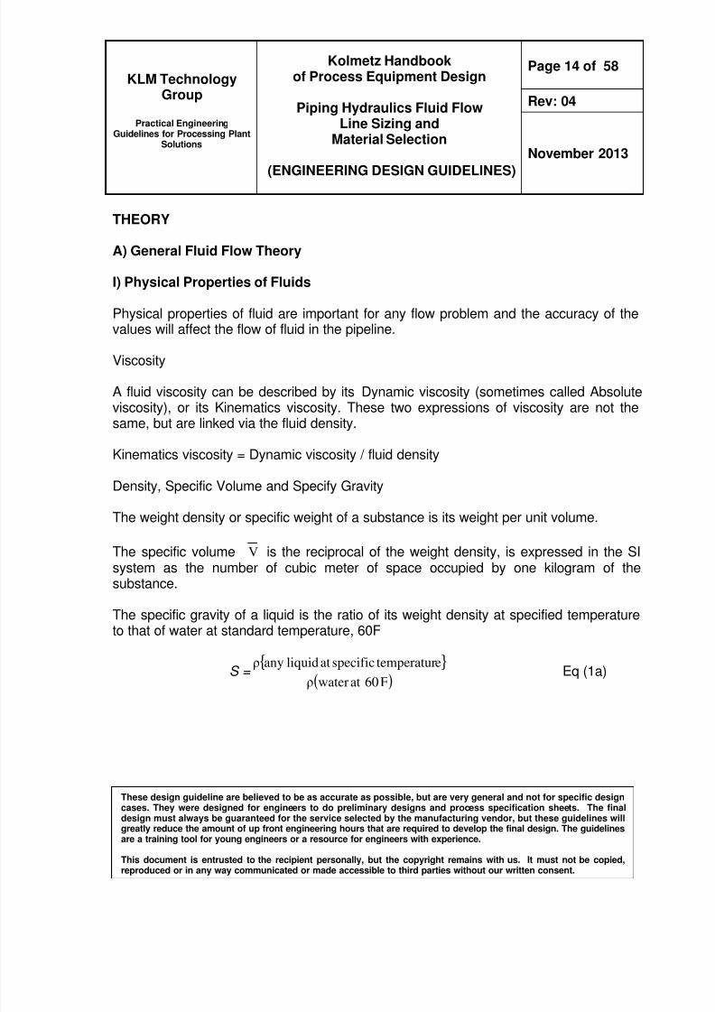
I) Physical Properties of Fluids
Physical properties of fluid are important for any flow problem and the accuracy of thevalues will affect the flow of fluid in the pipeline
Viscosity
A fluid viscosity can be described by its Dynamic viscosity (sometimes called Absoluteviscosity) or its Kinematics viscosity These two expressions of viscosity are not thesame but are linked via the fluid density
Kinematics viscosity = Dynamic viscosity fluid density
Density Specific Volume and Specify Gravity
The weight density or specific weight of a substance is its weight per unit volume
The specific volume V is the reciprocal of the weight density is expressed in the SIsystem as the number of cubic meter of space occupied by one kilogram of thesubstance
The specific gravity of a liquid is the ratio of its weight density at specified temperatureto that of water at standard temperature 60F
S =
( )F60atwaterρ
etemperaturspecificatliquidanyρ Eq (1a)
8102019 Kolmetz Handbook of Process Equipment Design
Practical EngineeringGuidelines for Processing Plant
Solutions
Kolmetz Handbookof Process Equipment Design
Piping Hydraulics Fluid FlowLine Sizing and
Material Selection
(ENGINEERING DESIGN GUIDELINES)
Page 15 of 58
Rev 04
November 2013
These design guideline are believed to be as accurate as possible but are very general and not for specific designcases They were designed for engineers to do preliminary designs and process specification sheets The finaldesign must always be guaranteed for the service selected by the manufacturing vendor but these guidelines willgreatly reduce the amount of up front engineering hours that are required to develop the final design The guidelinesare a training tool for young engineers or a resource for engineers with experience
This document is entrusted to the recipient personally but the copyright remains with us It must not be copied
reproduced or in any way communicated or made accessible to third parties without our written consent
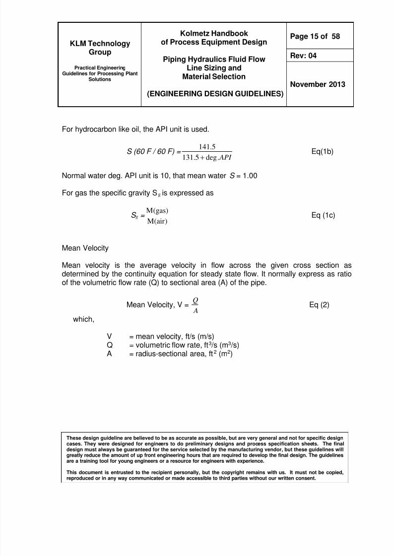
For hydrocarbon like oil the API unit is used
S (60 F 60 F) = API deg5131
5141
+ Eq(1b)
Normal water deg API unit is 10 that mean water S = 100
For gas the specific gravity Sg is expressed as
S g = )air(M
)gas(M Eq (1c)
Mean Velocity
Mean velocity is the average velocity in flow across the given cross section asdetermined by the continuity equation for steady state flow It normally express as ratio
of the volumetric flow rate (Q) to sectional area (A) of the pipe
Mean Velocity V = A
Q Eq (2)
which
V = mean velocity fts (ms)Q = volumetric flow rate ft3 s (m3 s)A = radius-sectional area ft2 (m2)
8102019 Kolmetz Handbook of Process Equipment Design
Practical EngineeringGuidelines for Processing Plant
Solutions
Kolmetz Handbookof Process Equipment Design
Piping Hydraulics Fluid FlowLine Sizing and
Material Selection
(ENGINEERING DESIGN GUIDELINES)
Page 16 of 58
Rev 04
November 2013
These design guideline are believed to be as accurate as possible but are very general and not for specific designcases They were designed for engineers to do preliminary designs and process specification sheets The finaldesign must always be guaranteed for the service selected by the manufacturing vendor but these guidelines willgreatly reduce the amount of up front engineering hours that are required to develop the final design The guidelinesare a training tool for young engineers or a resource for engineers with experience
This document is entrusted to the recipient personally but the copyright remains with us It must not be copied
reproduced or in any way communicated or made accessible to third parties without our written consent
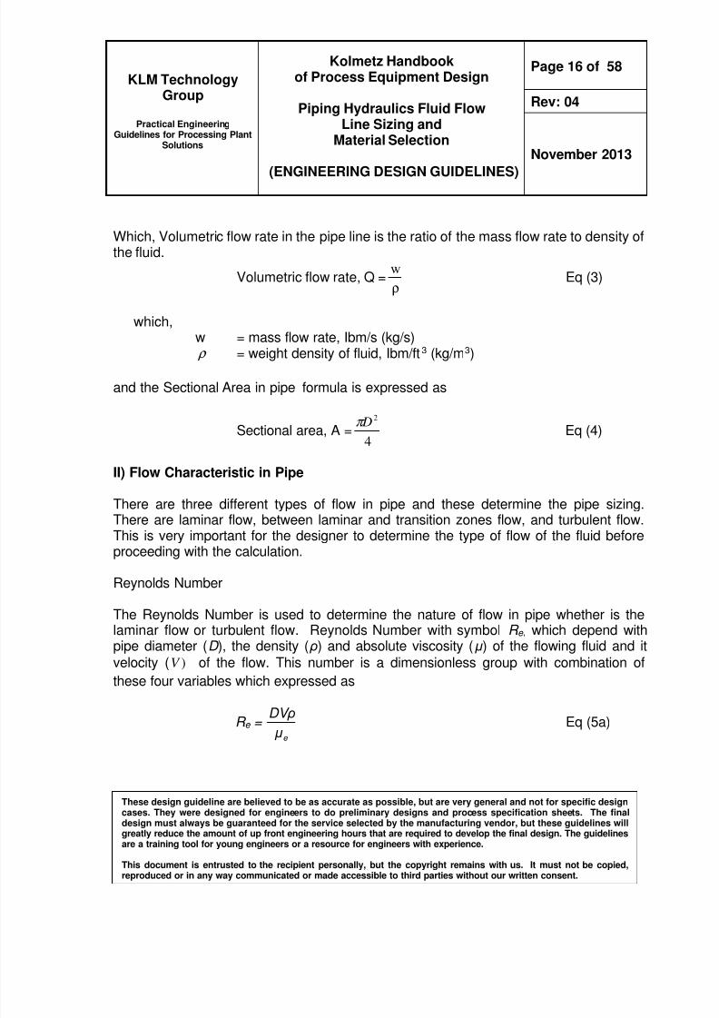
Which Volumetric flow rate in the pipe line is the ratio of the mass flow rate to density ofthe fluid
Volumetric flow rate Q =ρ
w Eq (3)
whichw = mass flow rate Ibms (kgs) ρ = weight density of fluid Ibmft3 (kgm3)
and the Sectional Area in pipe formula is expressed as
Sectional area A =4
2 Dπ Eq (4)
II) Flow Characteristic in Pipe
There are three different types of flow in pipe and these determine the pipe sizing
There are laminar flow between laminar and transition zones flow and turbulent flowThis is very important for the designer to determine the type of flow of the fluid beforeproceeding with the calculation
Reynolds Number
The Reynolds Number is used to determine the nature of flow in pipe whether is thelaminar flow or turbulent flow Reynolds Number with symbol R e which depend withpipe diameter (D ) the density ( ρ) and absolute viscosity ( μ ) of the flowing fluid and itvelocity ( )V of the flow This number is a dimensionless group with combination of
these four variables which expressed as
R e =e μ
DV ρ Eq (5a)
8102019 Kolmetz Handbook of Process Equipment Design
Practical EngineeringGuidelines for Processing Plant
Solutions
Kolmetz Handbookof Process Equipment Design
Piping Hydraulics Fluid FlowLine Sizing and
Material Selection
(ENGINEERING DESIGN GUIDELINES)
Page 17 of 58
Rev 04
November 2013
These design guideline are believed to be as accurate as possible but are very general and not for specific designcases They were designed for engineers to do preliminary designs and process specification sheets The finaldesign must always be guaranteed for the service selected by the manufacturing vendor but these guidelines willgreatly reduce the amount of up front engineering hours that are required to develop the final design The guidelinesare a training tool for young engineers or a resource for engineers with experience
This document is entrusted to the recipient personally but the copyright remains with us It must not be copied
reproduced or in any way communicated or made accessible to third parties without our written consent
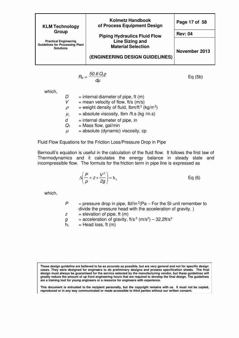
R e =d μ
Q 506 1ρ Eq (5b)
whichD = internal diameter of pipe ft (m)V = mean velocity of flow fts (ms) ρ = weight density of fluid Ibmft3 (kgm3)
e micro = absolute viscosity Ibm fts (kg ms)d = internal diameter of pipe inQ 1 = Mass flow galmin micro = absolute (dynamic) viscosity cp
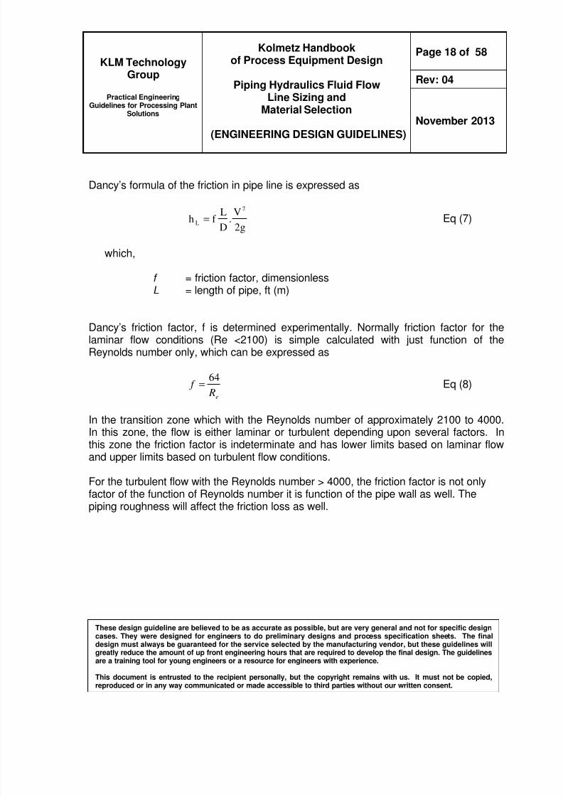
Fluid Flow Equations for the Friction LossPressure Drop in Pipe
Bernoullirsquos equation is useful in the calculation of the fluid flow It follows the first law ofThermodynamics and it calculates the energy balance in steady state andincompressible flow The formula for the friction term in pipe line is expressed as
Lh=
++∆
2g V z
ρ
P 2 Eq (6)
which
P = pressure drop in pipe Ibfin2(Pa ndash For the SI unit remember todivide the pressure head with the acceleration of gravity )
z = elevation of pipe ft (m)g = acceleration of gravity fts2 (ms2) ndash 322fts2 hL = Head loss ft (m)
8102019 Kolmetz Handbook of Process Equipment Design
Practical EngineeringGuidelines for Processing Plant
Solutions
Kolmetz Handbookof Process Equipment Design
Piping Hydraulics Fluid FlowLine Sizing and
Material Selection
(ENGINEERING DESIGN GUIDELINES)
Page 18 of 58
Rev 04
November 2013
These design guideline are believed to be as accurate as possible but are very general and not for specific designcases They were designed for engineers to do preliminary designs and process specification sheets The finaldesign must always be guaranteed for the service selected by the manufacturing vendor but these guidelines willgreatly reduce the amount of up front engineering hours that are required to develop the final design The guidelinesare a training tool for young engineers or a resource for engineers with experience
This document is entrusted to the recipient personally but the copyright remains with us It must not be copied
reproduced or in any way communicated or made accessible to third parties without our written consent
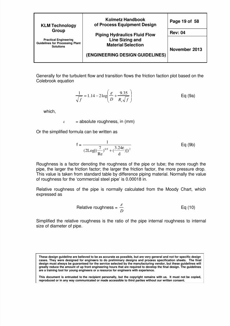
Dancyrsquos formula of the friction in pipe line is expressed as
g2
V
D
Lf h
2
L = Eq (7)
which
f = friction factor dimensionlessL = length of pipe ft (m)
Dancyrsquos friction factor f is determined experimentally Normally friction factor for thelaminar flow conditions (Re lt2100) is simple calculated with just function of theReynolds number only which can be expressed as
e R f
64= Eq (8)
In the transition zone which with the Reynolds number of approximately 2100 to 4000In this zone the flow is either laminar or turbulent depending upon several factors Inthis zone the friction factor is indeterminate and has lower limits based on laminar flowand upper limits based on turbulent flow conditions
For the turbulent flow with the Reynolds number gt 4000 the friction factor is not onlyfactor of the function of Reynolds number it is function of the pipe wall as well Thepiping roughness will affect the friction loss as well
8102019 Kolmetz Handbook of Process Equipment Design
Practical EngineeringGuidelines for Processing Plant
Solutions
Kolmetz Handbookof Process Equipment Design
Piping Hydraulics Fluid FlowLine Sizing and
Material Selection
(ENGINEERING DESIGN GUIDELINES)
Page 19 of 58
Rev 04
November 2013
These design guideline are believed to be as accurate as possible but are very general and not for specific designcases They were designed for engineers to do preliminary designs and process specification sheets The finaldesign must always be guaranteed for the service selected by the manufacturing vendor but these guidelines willgreatly reduce the amount of up front engineering hours that are required to develop the final design The guidelinesare a training tool for young engineers or a resource for engineers with experience
This document is entrusted to the recipient personally but the copyright remains with us It must not be copied
reproduced or in any way communicated or made accessible to third parties without our written consent
Generally for the turbulent flow and transition flows the friction faction plot based on theColebrook equation
+minus=
f R D f e
359log2141
1 ε Eq (9a)
which
ε = absolute roughness in (mm)
Or the simplified formula can be written as
f =290 )])
d
243()
Re
7[(Log2(
1
ε+
Eq (9b)
Roughness is a factor denoting the roughness of the pipe or tube the more rough the
pipe the larger the friction factor the larger the friction factor the more pressure dropThis value is taken from standard table by difference piping material Normally the valueof roughness for the lsquocommercial steel pipersquo is 000018 in
Relative roughness of the pipe is normally calculated from the Moody Chart whichexpressed as
Relative roughness = D
ε Eq (10)
Simplified the relative roughness is the ratio of the pipe internal roughness to internalsize of diameter of pipe
8102019 Kolmetz Handbook of Process Equipment Design
Practical EngineeringGuidelines for Processing Plant
Solutions
Kolmetz Handbookof Process Equipment Design
Piping Hydraulics Fluid FlowLine Sizing and
Material Selection
(ENGINEERING DESIGN GUIDELINES)
Page 20 of 58
Rev 04
November 2013
These design guideline are believed to be as accurate as possible but are very general and not for specific designcases They were designed for engineers to do preliminary designs and process specification sheets The finaldesign must always be guaranteed for the service selected by the manufacturing vendor but these guidelines willgreatly reduce the amount of up front engineering hours that are required to develop the final design The guidelinesare a training tool for young engineers or a resource for engineers with experience
This document is entrusted to the recipient personally but the copyright remains with us It must not be copied
reproduced or in any way communicated or made accessible to third parties without our written consent
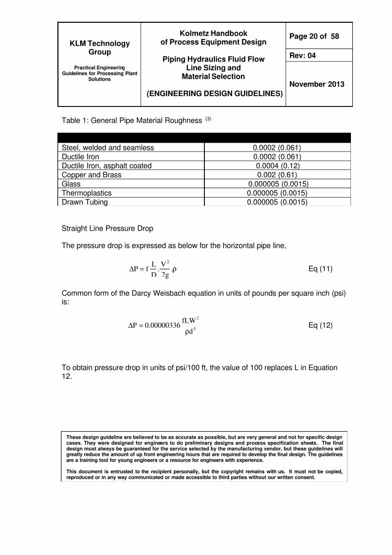
Table 1 General Pipe Material Roughness (3)
Pipe Material Roughness εεεε in (mm)Steel welded and seamless 00002 (0061)Ductile Iron 00002 (0061)Ductile Iron asphalt coated 00004 (012)Copper and Brass 0002 (061)
Practical EngineeringGuidelines for Processing Plant
Solutions
Kolmetz Handbookof Process Equipment Design
Piping Hydraulics Fluid FlowLine Sizing and
Material Selection
(ENGINEERING DESIGN GUIDELINES)
Page 21 of 58
Rev 04
November 2013
These design guideline are believed to be as accurate as possible but are very general and not for specific designcases They were designed for engineers to do preliminary designs and process specification sheets The finaldesign must always be guaranteed for the service selected by the manufacturing vendor but these guidelines willgreatly reduce the amount of up front engineering hours that are required to develop the final design The guidelinesare a training tool for young engineers or a resource for engineers with experience
This document is entrusted to the recipient personally but the copyright remains with us It must not be copied
reproduced or in any way communicated or made accessible to third parties without our written consent
In the non-horizontal pipe line pressure drop is expressed
z) ρ( ρP)( e ∆==∆ Lh Eq (13)
For the velocity change the in pressure drop the formula is expressed as
g2
V
h
2
L
∆ρ
==∆ ρP)( k Eq (14)
Effect of Valve Fitting on Pressure Drop
In the fluid systems the effect of valves elbows and etc on the pressure drop is neededto be taken into consideration when designing
General pressure drop in the fitting expressed as formula for the laminar flow andturbulent flow
)2
(2
gV K
ρP ft =∆ Eq (15)
Which
K = resistance coefficient dimensionless
ft P∆ = Pressure Drop in specific fitting Ibfin2 (Pa)
K = f t D
Leq
Eq (16)
8102019 Kolmetz Handbook of Process Equipment Design
Practical EngineeringGuidelines for Processing Plant
Solutions
Kolmetz Handbookof Process Equipment Design
Piping Hydraulics Fluid FlowLine Sizing and
Material Selection
(ENGINEERING DESIGN GUIDELINES)
Page 22 of 58
Rev 04
November 2013
These design guideline are believed to be as accurate as possible but are very general and not for specific designcases They were designed for engineers to do preliminary designs and process specification sheets The finaldesign must always be guaranteed for the service selected by the manufacturing vendor but these guidelines willgreatly reduce the amount of up front engineering hours that are required to develop the final design The guidelinesare a training tool for young engineers or a resource for engineers with experience
This document is entrusted to the recipient personally but the copyright remains with us It must not be copied
reproduced or in any way communicated or made accessible to third parties without our written consent
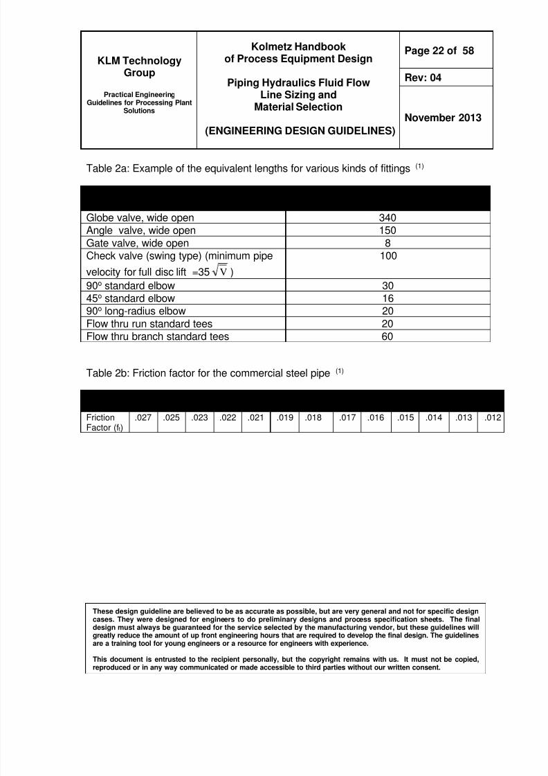
Table 2a Example of the equivalent lengths for various kinds of fittings (1)
Type of Fitting Equivalent Length LeqD(dimensionless)
Globe valve wide open 340Angle valve wide open 150
Gate valve wide open 8Check valve (swing type) (minimum pipe
velocity for full disc lift =35 V )
100
90o standard elbow 3045o standard elbow 1690o long-radius elbow 20
Flow thru run standard tees 20Flow thru branch standard tees 60
Table 2b Friction factor for the commercial steel pipe (1)
Practical EngineeringGuidelines for Processing Plant
Solutions
Kolmetz Handbookof Process Equipment Design
Piping Hydraulics Fluid FlowLine Sizing and
Material Selection
(ENGINEERING DESIGN GUIDELINES)
Page 23 of 58
Rev 04
November 2013
These design guideline are believed to be as accurate as possible but are very general and not for specific designcases They were designed for engineers to do preliminary designs and process specification sheets The finaldesign must always be guaranteed for the service selected by the manufacturing vendor but these guidelines willgreatly reduce the amount of up front engineering hours that are required to develop the final design The guidelinesare a training tool for young engineers or a resource for engineers with experience
This document is entrusted to the recipient personally but the copyright remains with us It must not be copied
reproduced or in any way communicated or made accessible to third parties without our written consent
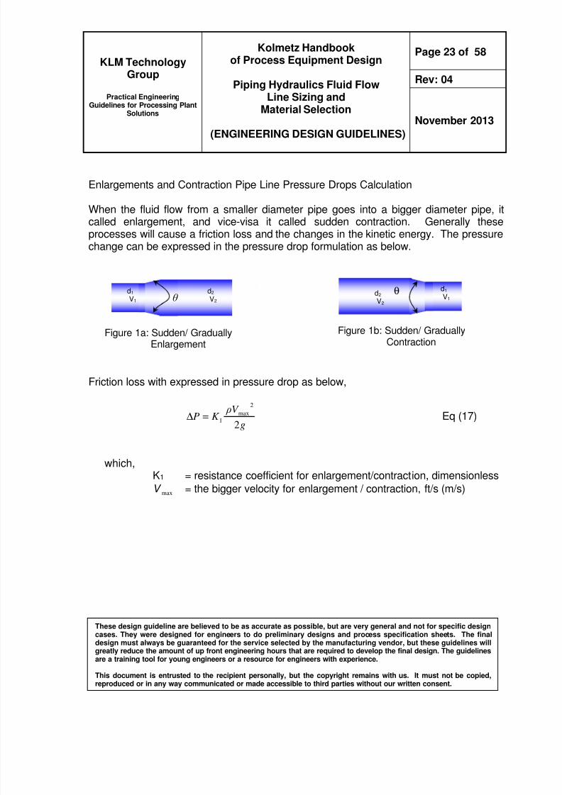
Enlargements and Contraction Pipe Line Pressure Drops Calculation
When the fluid flow from a smaller diameter pipe goes into a bigger diameter pipe itcalled enlargement and vice-visa it called sudden contraction Generally theseprocesses will cause a friction loss and the changes in the kinetic energy The pressurechange can be expressed in the pressure drop formulation as below
Friction loss with expressed in pressure drop as below
gV ρK P2
2
max
1=∆ Eq (17)
whichK1 = resistance coefficient for enlargementcontraction dimensionless
V max = the bigger velocity for enlargement contraction fts (ms)
d2 V2
d1 V1
Figure 1b Sudden GraduallyContraction
θ
Figure 1a Sudden GraduallyEnlargement
d1 V1 θ
d2 V2
8102019 Kolmetz Handbook of Process Equipment Design
Practical EngineeringGuidelines for Processing Plant
Solutions
Kolmetz Handbookof Process Equipment Design
Piping Hydraulics Fluid FlowLine Sizing and
Material Selection
(ENGINEERING DESIGN GUIDELINES)
Page 24 of 58
Rev 04
November 2013
These design guideline are believed to be as accurate as possible but are very general and not for specific designcases They were designed for engineers to do preliminary designs and process specification sheets The finaldesign must always be guaranteed for the service selected by the manufacturing vendor but these guidelines willgreatly reduce the amount of up front engineering hours that are required to develop the final design The guidelinesare a training tool for young engineers or a resource for engineers with experience
This document is entrusted to the recipient personally but the copyright remains with us It must not be copied
reproduced or in any way communicated or made accessible to third parties without our written consent
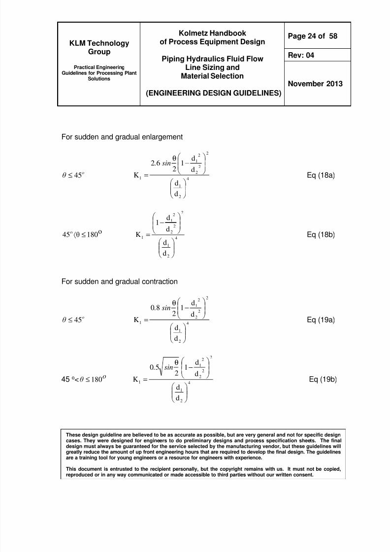
For sudden and gradual enlargement
oθ 45le
4
2
1
2
2
2
2
1
1
d
d
d
d1
262
K
minus
θ
=
sin
Eq (18a)
o180θ45o lelang 4
2
1
2
2
2
2
1
1
d
d
d
d1
K
minus
= Eq (18b)
For sudden and gradual contraction
oθ 45le
4
2
1
2
2
2
2
1
1
d
d
d
d1
280
K
minus
θ
=
sin
Eq (19a)
45 olt oθ 180le 4
2
1
2
2
2
2
1
1
d
d
d
d1
250
K
minus
θ
=
sin
Eq (19b)
8102019 Kolmetz Handbook of Process Equipment Design
Practical EngineeringGuidelines for Processing Plant
Solutions
Kolmetz Handbookof Process Equipment Design
Piping Hydraulics Fluid FlowLine Sizing and
Material Selection
(ENGINEERING DESIGN GUIDELINES)
Page 25 of 58
Rev 04
November 2013
These design guideline are believed to be as accurate as possible but are very general and not for specific designcases They were designed for engineers to do preliminary designs and process specification sheets The finaldesign must always be guaranteed for the service selected by the manufacturing vendor but these guidelines willgreatly reduce the amount of up front engineering hours that are required to develop the final design The guidelinesare a training tool for young engineers or a resource for engineers with experience
This document is entrusted to the recipient personally but the copyright remains with us It must not be copied
reproduced or in any way communicated or made accessible to third parties without our written consent
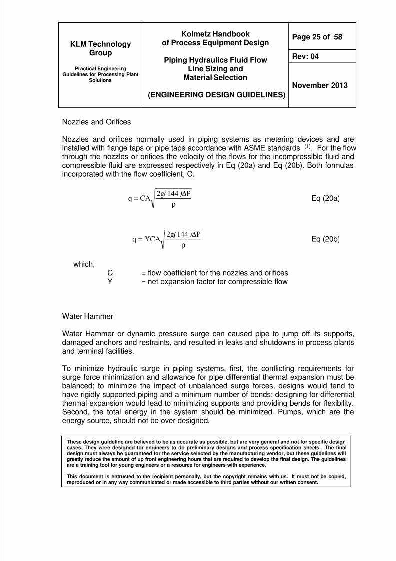
Nozzles and Orifices
Nozzles and orifices normally used in piping systems as metering devices and areinstalled with flange taps or pipe taps accordance with ASME standards (1) For the flowthrough the nozzles or orifices the velocity of the flows for the incompressible fluid andcompressible fluid are expressed respectively in Eq (20a) and Eq (20b) Both formulasincorporated with the flow coefficient C
ρ
∆= P144g2CAq )( Eq (20a)
ρ
∆=
P144g2YCAq
)( Eq (20b)
whichC = flow coefficient for the nozzles and orificesY = net expansion factor for compressible flow
Water Hammer
Water Hammer or dynamic pressure surge can caused pipe to jump off its supportsdamaged anchors and restraints and resulted in leaks and shutdowns in process plantsand terminal facilities
To minimize hydraulic surge in piping systems first the conflicting requirements forsurge force minimization and allowance for pipe differential thermal expansion must be
balanced to minimize the impact of unbalanced surge forces designs would tend tohave rigidly supported piping and a minimum number of bends designing for differentialthermal expansion would lead to minimizing supports and providing bends for flexibilitySecond the total energy in the system should be minimized Pumps which are theenergy source should not be over designed
8102019 Kolmetz Handbook of Process Equipment Design
Practical EngineeringGuidelines for Processing Plant
Solutions
Kolmetz Handbookof Process Equipment Design
Piping Hydraulics Fluid FlowLine Sizing and
Material Selection
(ENGINEERING DESIGN GUIDELINES)
Page 26 of 58
Rev 04
November 2013
These design guideline are believed to be as accurate as possible but are very general and not for specific designcases They were designed for engineers to do preliminary designs and process specification sheets The finaldesign must always be guaranteed for the service selected by the manufacturing vendor but these guidelines willgreatly reduce the amount of up front engineering hours that are required to develop the final design The guidelinesare a training tool for young engineers or a resource for engineers with experience
This document is entrusted to the recipient personally but the copyright remains with us It must not be copied
reproduced or in any way communicated or made accessible to third parties without our written consent
General design recommendations for minimizing surge forces are
Minimize the number of bends used in the system Use the largest enclosed angle and radius possible for bends Bend to bend distance should be as far as possible Provide supports near all large components Provide bypasses at pump stations
Install control valves on pump discharges Limit flow velocity to a maximum of 10 ftsec (3 ms) in pipes and 35 ftsec (10
ms) in loading arms
General rule closure times of valves in pipes up to 24 in (600 mm) in diameter shouldexceed 15 seconds For pipe diameters of 24 in (600 mm) or larger the closure timeshould be at least 30 seconds Valve operators of the air pneumatic piston type shouldbe avoided because they may cause pressure surges due to sudden closing of valvesIf surge forces are unavoidable protection devices should be used including safetyvalves or rupture disks for tube split protection on high pressure exchangers pulsationbottle for positive displacement pumps LPG line surge drums etc
B) Piping Fluid Flow Material Selection
Many factors have to be considered when selecting engineering materials for the pipingNormally the material selections of piping it depend on the application refer Table 3
The most economical material that satisfies both process and mechanical requirementsshould be selected this will be the material that gives the lowest cost over the workinglife of the plant allowing for maintenance and replacement for the piping (3)
8102019 Kolmetz Handbook of Process Equipment Design
Practical EngineeringGuidelines for Processing Plant
Solutions
Kolmetz Handbookof Process Equipment Design
Piping Hydraulics Fluid FlowLine Sizing and
Material Selection
(ENGINEERING DESIGN GUIDELINES)
Page 27 of 58
Rev 04
November 2013
These design guideline are believed to be as accurate as possible but are very general and not for specific designcases They were designed for engineers to do preliminary designs and process specification sheets The finaldesign must always be guaranteed for the service selected by the manufacturing vendor but these guidelines willgreatly reduce the amount of up front engineering hours that are required to develop the final design The guidelinesare a training tool for young engineers or a resource for engineers with experience
This document is entrusted to the recipient personally but the copyright remains with us It must not be copied
reproduced or in any way communicated or made accessible to third parties without our written consent
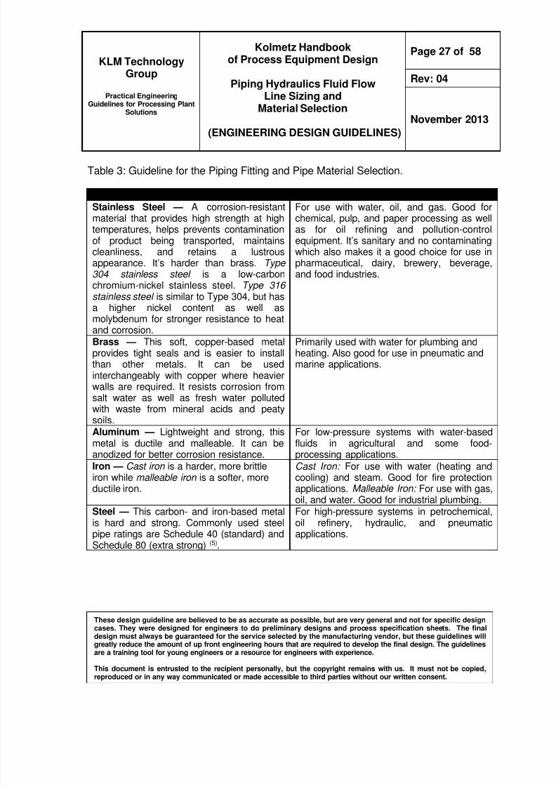
Table 3 Guideline for the Piping Fitting and Pipe Material Selection
Type of Material amp Features General Applications
Stainless Steel mdash A corrosion-resistantmaterial that provides high strength at hightemperatures helps prevents contaminationof product being transported maintainscleanliness and retains a lustrousappearance Itrsquos harder than brass Type304 stainless steel is a low-carbonchromium-nickel stainless steel Type 316stainless steel is similar to Type 304 but hasa higher nickel content as well asmolybdenum for stronger resistance to heatand corrosion
For use with water oil and gas Good forchemical pulp and paper processing as wellas for oil refining and pollution-controlequipment Itrsquos sanitary and no contaminatingwhich also makes it a good choice for use inpharmaceutical dairy brewery beverageand food industries
Brass mdash This soft copper-based metalprovides tight seals and is easier to installthan other metals It can be usedinterchangeably with copper where heavierwalls are required It resists corrosion fromsalt water as well as fresh water pollutedwith waste from mineral acids and peatysoils
Primarily used with water for plumbing andheating Also good for use in pneumatic andmarine applications
Aluminum mdash Lightweight and strong thismetal is ductile and malleable It can beanodized for better corrosion resistance
For low-pressure systems with water-basedfluids in agricultural and some food-processing applications
Iron mdash Cast iron is a harder more brittleiron while malleable iron is a softer moreductile iron
Cast Iron For use with water (heating andcooling) and steam Good for fire protectionapplications Malleable Iron For use with gasoil and water Good for industrial plumbing
Steel mdash This carbon- and iron-based metalis hard and strong Commonly used steelpipe ratings are Schedule 40 (standard) andSchedule 80 (extra strong) (5)
For high-pressure systems in petrochemicaloil refinery hydraulic and pneumaticapplications
8102019 Kolmetz Handbook of Process Equipment Design
Practical EngineeringGuidelines for Processing Plant
Solutions
Kolmetz Handbookof Process Equipment Design
Piping Hydraulics Fluid FlowLine Sizing and
Material Selection
(ENGINEERING DESIGN GUIDELINES)
Page 28 of 58
Rev 04
November 2013
These design guideline are believed to be as accurate as possible but are very general and not for specific designcases They were designed for engineers to do preliminary designs and process specification sheets The finaldesign must always be guaranteed for the service selected by the manufacturing vendor but these guidelines willgreatly reduce the amount of up front engineering hours that are required to develop the final design The guidelinesare a training tool for young engineers or a resource for engineers with experience
This document is entrusted to the recipient personally but the copyright remains with us It must not be copied
reproduced or in any way communicated or made accessible to third parties without our written consent
Once the material of construction is selected the selected piping it should be selectedbased on piping schedule pipe diameter (inside or outside diameter) and pipe wallthickness which cover under the standards codes Below are the standards codescovers
1 American Standard ASME B36102 American Standard ASME B3619
3 New United States Legal Standard for Steel Plate Gauges
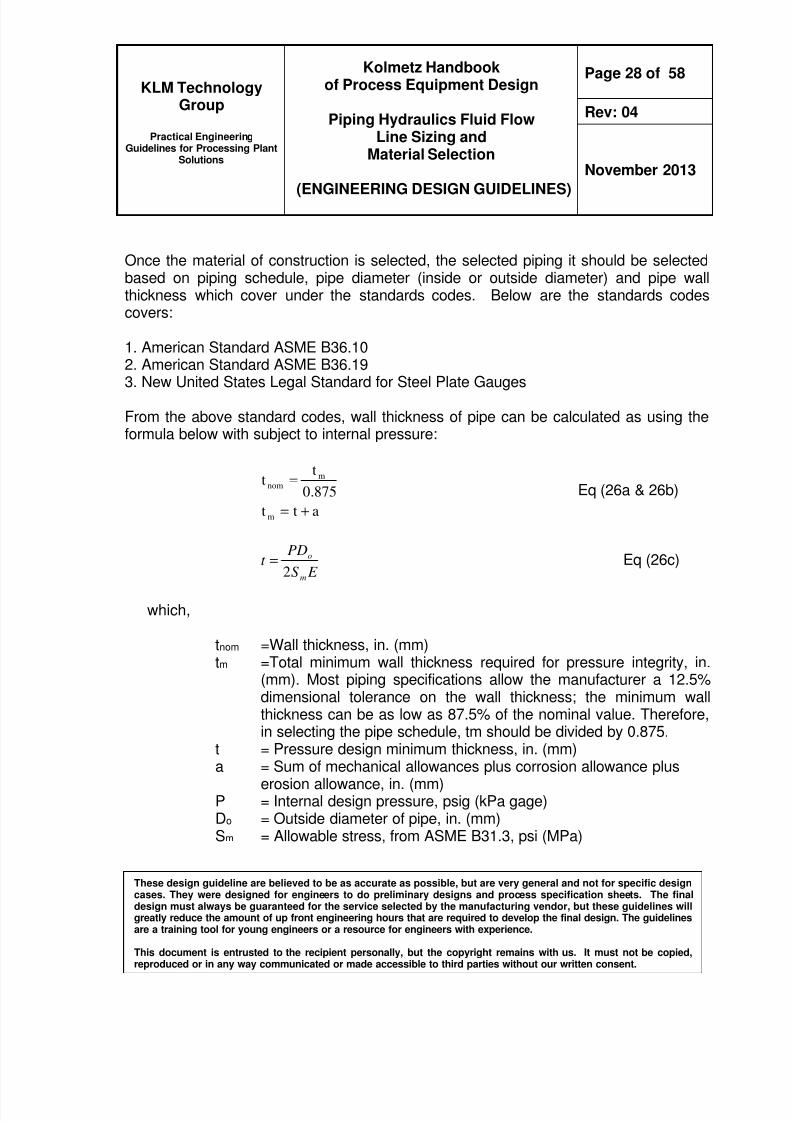
From the above standard codes wall thickness of pipe can be calculated as using theformula below with subject to internal pressure
att
8750
tt
m
mnom
+=
= Eq (26a amp 26b)
E S
PDt
m
o
2
= Eq (26c)
which
tnom =Wall thickness in (mm)tm =Total minimum wall thickness required for pressure integrity in
(mm) Most piping specifications allow the manufacturer a 125dimensional tolerance on the wall thickness the minimum wallthickness can be as low as 875 of the nominal value Thereforein selecting the pipe schedule tm should be divided by 0875
t = Pressure design minimum thickness in (mm)
a = Sum of mechanical allowances plus corrosion allowance pluserosion allowance in (mm)
P = Internal design pressure psig (kPa gage)Do = Outside diameter of pipe in (mm)Sm = Allowable stress from ASME B313 psi (MPa)
8102019 Kolmetz Handbook of Process Equipment Design
Practical EngineeringGuidelines for Processing Plant
Solutions
Kolmetz Handbookof Process Equipment Design
Piping Hydraulics Fluid FlowLine Sizing and
Material Selection
(ENGINEERING DESIGN GUIDELINES)
Page 29 of 58
Rev 04
November 2013
These design guideline are believed to be as accurate as possible but are very general and not for specific designcases They were designed for engineers to do preliminary designs and process specification sheets The finaldesign must always be guaranteed for the service selected by the manufacturing vendor but these guidelines willgreatly reduce the amount of up front engineering hours that are required to develop the final design The guidelinesare a training tool for young engineers or a resource for engineers with experience
This document is entrusted to the recipient personally but the copyright remains with us It must not be copied
reproduced or in any way communicated or made accessible to third parties without our written consent
E = Weld joint efficiency or quality factor from ASME B313 Exampleseamless pipe E = 10
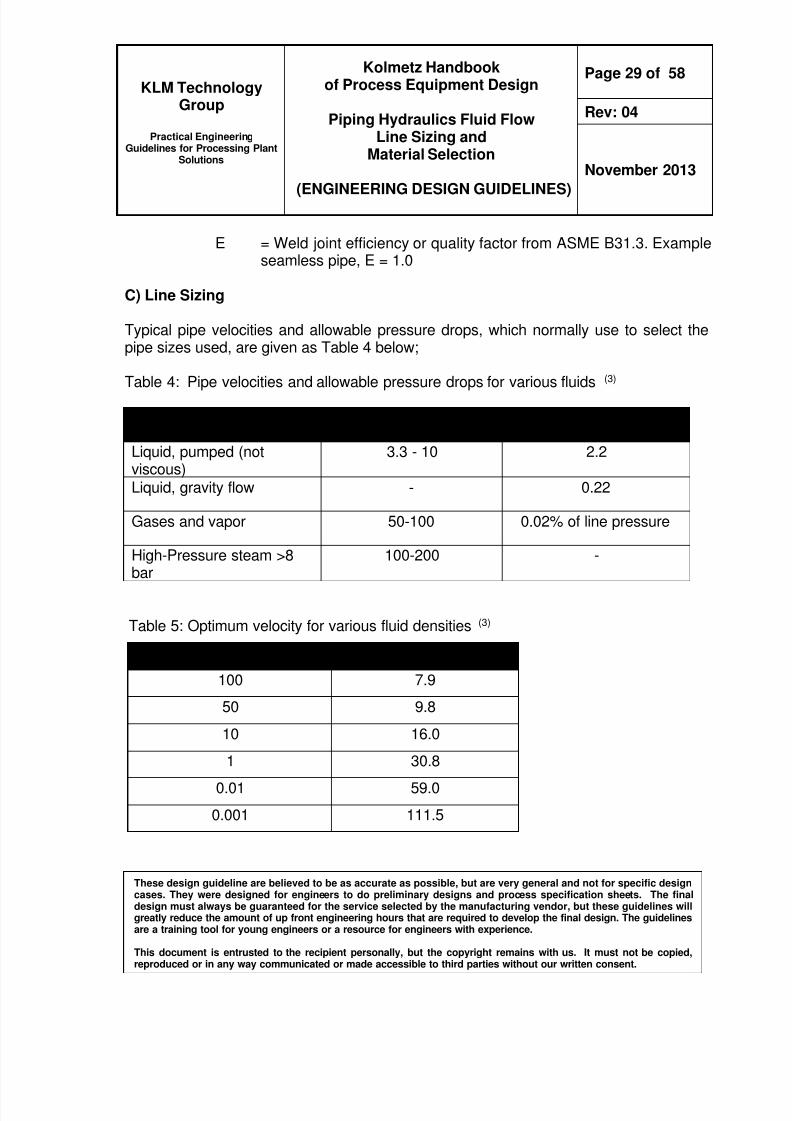
C) Line Sizing
Typical pipe velocities and allowable pressure drops which normally use to select thepipe sizes used are given as Table 4 below
Table 4 Pipe velocities and allowable pressure drops for various fluids(3)
Type of Fluid Velocity ftsec ∆∆∆∆P in psi100ft
Liquid pumped (notviscous)
33 - 10 22
Liquid gravity flow - 022
Gases and vapor 50-100 002 of line pressure
High-Pressure steam gt8
bar
100-200 -
Table 5 Optimum velocity for various fluid densities (3)
Fluid density Ibft3 Velocity ftsec
100 79
50 98
10 160
1 308001 590
0001 1115
8102019 Kolmetz Handbook of Process Equipment Design
Practical EngineeringGuidelines for Processing Plant
Solutions
Kolmetz Handbookof Process Equipment Design
Piping Hydraulics Fluid FlowLine Sizing and
Material Selection
(ENGINEERING DESIGN GUIDELINES)
Page 30 of 58
Rev 04
November 2013
These design guideline are believed to be as accurate as possible but are very general and not for specific designcases They were designed for engineers to do preliminary designs and process specification sheets The finaldesign must always be guaranteed for the service selected by the manufacturing vendor but these guidelines willgreatly reduce the amount of up front engineering hours that are required to develop the final design The guidelinesare a training tool for young engineers or a resource for engineers with experience
This document is entrusted to the recipient personally but the copyright remains with us It must not be copied
reproduced or in any way communicated or made accessible to third parties without our written consent
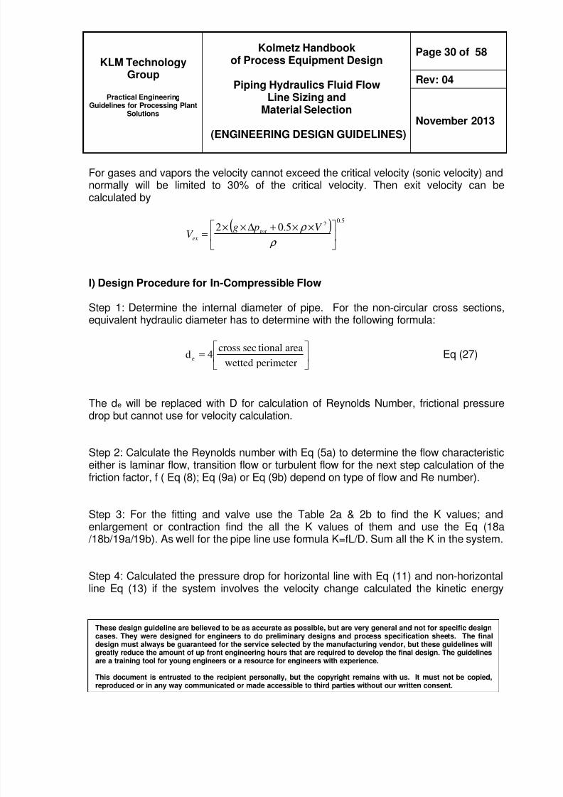
For gases and vapors the velocity cannot exceed the critical velocity (sonic velocity) andnormally will be limited to 30 of the critical velocity Then exit velocity can becalculated by
( )50
2502
timestimes+∆timestimes=
ρ
ρ V pgV tot
ex
I) Design Procedure for In-Compressible Flow
Step 1 Determine the internal diameter of pipe For the non-circular cross sectionsequivalent hydraulic diameter has to determine with the following formula
=
perimeterwetted
areationalseccross4d e Eq (27)
The de will be replaced with D for calculation of Reynolds Number frictional pressuredrop but cannot use for velocity calculation
Step 2 Calculate the Reynolds number with Eq (5a) to determine the flow characteristiceither is laminar flow transition flow or turbulent flow for the next step calculation of thefriction factor f ( Eq (8) Eq (9a) or Eq (9b) depend on type of flow and Re number)
Step 3 For the fitting and valve use the Table 2a amp 2b to find the K values andenlargement or contraction find the all the K values of them and use the Eq (18a
18b19a19b) As well for the pipe line use formula K=fLD Sum all the K in the system
Step 4 Calculated the pressure drop for horizontal line with Eq (11) and non-horizontalline Eq (13) if the system involves the velocity change calculated the kinetic energy
8102019 Kolmetz Handbook of Process Equipment Design
Practical EngineeringGuidelines for Processing Plant
Solutions
Kolmetz Handbookof Process Equipment Design
Piping Hydraulics Fluid FlowLine Sizing and
Material Selection
(ENGINEERING DESIGN GUIDELINES)
Page 31 of 58
Rev 04
November 2013
These design guideline are believed to be as accurate as possible but are very general and not for specific designcases They were designed for engineers to do preliminary designs and process specification sheets The finaldesign must always be guaranteed for the service selected by the manufacturing vendor but these guidelines willgreatly reduce the amount of up front engineering hours that are required to develop the final design The guidelinesare a training tool for young engineers or a resource for engineers with experience
This document is entrusted to the recipient personally but the copyright remains with us It must not be copied
reproduced or in any way communicated or made accessible to third parties without our written consent
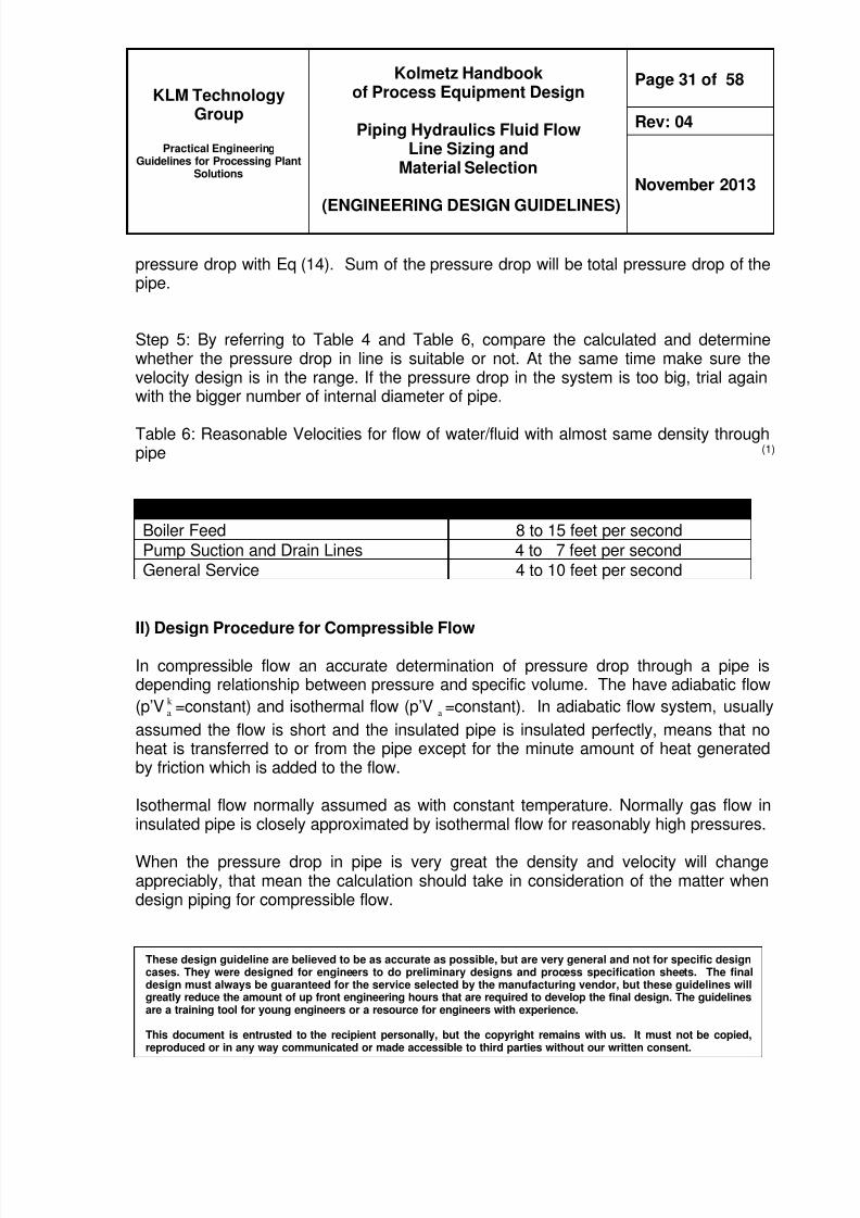
pressure drop with Eq (14) Sum of the pressure drop will be total pressure drop of thepipe
Step 5 By referring to Table 4 and Table 6 compare the calculated and determinewhether the pressure drop in line is suitable or not At the same time make sure thevelocity design is in the range If the pressure drop in the system is too big trial againwith the bigger number of internal diameter of pipe
Table 6 Reasonable Velocities for flow of waterfluid with almost same density throughpipe (1)
Service Condition Reasonable VelocityBoiler Feed 8 to 15 feet per secondPump Suction and Drain Lines 4 to 7 feet per secondGeneral Service 4 to 10 feet per second
II) Design Procedure for Compressible Flow
In compressible flow an accurate determination of pressure drop through a pipe isdepending relationship between pressure and specific volume The have adiabatic flow
(prsquoV k
a =constant) and isothermal flow (prsquoV a =constant) In adiabatic flow system usually
assumed the flow is short and the insulated pipe is insulated perfectly means that noheat is transferred to or from the pipe except for the minute amount of heat generatedby friction which is added to the flow
Isothermal flow normally assumed as with constant temperature Normally gas flow ininsulated pipe is closely approximated by isothermal flow for reasonably high pressures
When the pressure drop in pipe is very great the density and velocity will changeappreciably that mean the calculation should take in consideration of the matter whendesign piping for compressible flow
8102019 Kolmetz Handbook of Process Equipment Design
Practical EngineeringGuidelines for Processing Plant
Solutions
Kolmetz Handbookof Process Equipment Design
Piping Hydraulics Fluid FlowLine Sizing and
Material Selection
(ENGINEERING DESIGN GUIDELINES)
Page 32 of 58
Rev 04
November 2013
These design guideline are believed to be as accurate as possible but are very general and not for specific designcases They were designed for engineers to do preliminary designs and process specification sheets The finaldesign must always be guaranteed for the service selected by the manufacturing vendor but these guidelines willgreatly reduce the amount of up front engineering hours that are required to develop the final design The guidelinesare a training tool for young engineers or a resource for engineers with experience
This document is entrusted to the recipient personally but the copyright remains with us It must not be copied
reproduced or in any way communicated or made accessible to third parties without our written consent
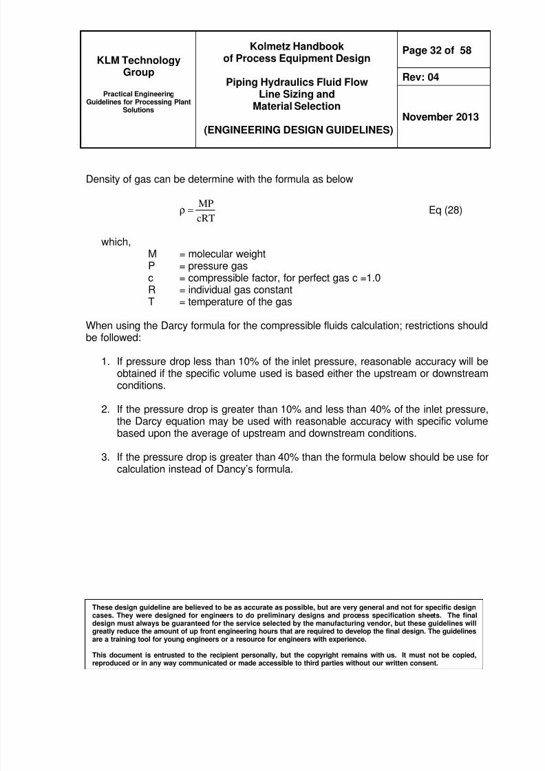
Density of gas can be determine with the formula as below
cRT
MP=ρ Eq (28)
whichM = molecular weight
P = pressure gasc = compressible factor for perfect gas c =10R = individual gas constantT = temperature of the gas
When using the Darcy formula for the compressible fluids calculation restrictions shouldbe followed
1 If pressure drop less than 10 of the inlet pressure reasonable accuracy will beobtained if the specific volume used is based either the upstream or downstreamconditions
2 If the pressure drop is greater than 10 and less than 40 of the inlet pressurethe Darcy equation may be used with reasonable accuracy with specific volumebased upon the average of upstream and downstream conditions
3 If the pressure drop is greater than 40 than the formula below should be use forcalculation instead of Dancyrsquos formula
8102019 Kolmetz Handbook of Process Equipment Design
Practical EngineeringGuidelines for Processing Plant
Solutions
Kolmetz Handbookof Process Equipment Design
Piping Hydraulics Fluid FlowLine Sizing and
Material Selection
(ENGINEERING DESIGN GUIDELINES)
Page 33 of 58
Rev 04
November 2013
These design guideline are believed to be as accurate as possible but are very general and not for specific designcases They were designed for engineers to do preliminary designs and process specification sheets The finaldesign must always be guaranteed for the service selected by the manufacturing vendor but these guidelines willgreatly reduce the amount of up front engineering hours that are required to develop the final design The guidelinesare a training tool for young engineers or a resource for engineers with experience
This document is entrusted to the recipient personally but the copyright remains with us It must not be copied
reproduced or in any way communicated or made accessible to third parties without our written consent
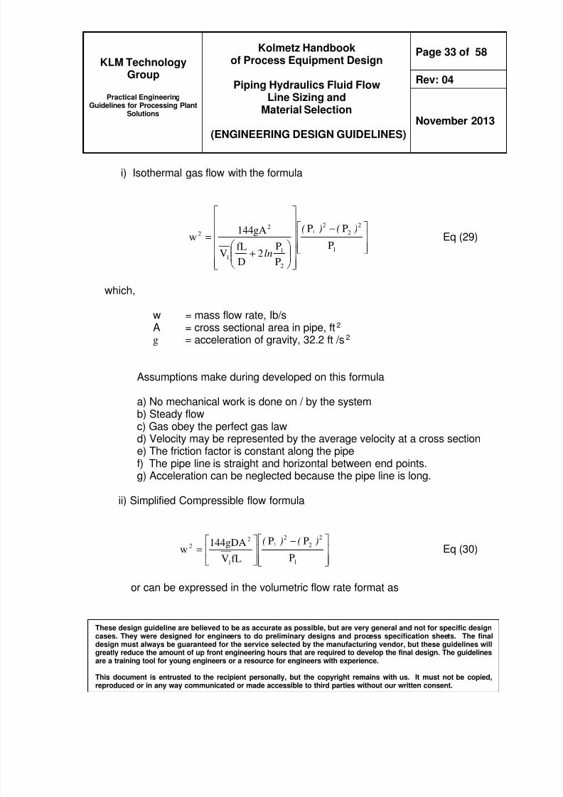
i) Isothermal gas flow with the formula
minus
+
=1
2
2
2
2
11
22
P
PP
P
P2
D
fLV
gA144w
1 )()(
ln
Eq (29)
which
w = mass flow rate IbsA = cross sectional area in pipe ft2 g = acceleration of gravity 322 ft s2
Assumptions make during developed on this formula
a) No mechanical work is done on by the systemb) Steady flowc) Gas obey the perfect gas lawd) Velocity may be represented by the average velocity at a cross sectione) The friction factor is constant along the pipef) The pipe line is straight and horizontal between end pointsg) Acceleration can be neglected because the pipe line is long
ii) Simplified Compressible flow formula
minus
=
1
2
2
2
1
2
2
P
PP
fLVgDA144w
1 )()( Eq (30)
or can be expressed in the volumetric flow rate format as
8102019 Kolmetz Handbook of Process Equipment Design
Practical EngineeringGuidelines for Processing Plant
Solutions
Kolmetz Handbookof Process Equipment Design
Piping Hydraulics Fluid FlowLine Sizing and
Material Selection
(ENGINEERING DESIGN GUIDELINES)
Page 34 of 58
Rev 04
November 2013
These design guideline are believed to be as accurate as possible but are very general and not for specific designcases They were designed for engineers to do preliminary designs and process specification sheets The finaldesign must always be guaranteed for the service selected by the manufacturing vendor but these guidelines willgreatly reduce the amount of up front engineering hours that are required to develop the final design The guidelinesare a training tool for young engineers or a resource for engineers with experience
This document is entrusted to the recipient personally but the copyright remains with us It must not be copied
reproduced or in any way communicated or made accessible to third parties without our written consent
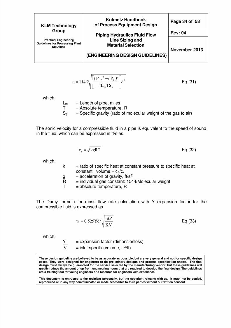
5
gm
2
2
2
dTSfL
PP2114q
1
minus=
)()( Eq (31)
whichLm = Length of pipe milesT = Absolute temperature R
Sg = Specific gravity (ratio of molecular weight of the gas to air)
The sonic velocity for a compressible fluid in a pipe is equivalent to the speed of soundin the fluid which can be expressed in fts as
kgRTvs = Eq (32)
whichk = ratio of specific heat at constant pressure to specific heat at
constant volume = cp cv
g = acceleration of gravity fts2 R = individual gas constant 1544Molecular weightT = absolute temperature R
The Darcy formula for mass flow rate calculation with Y expansion factor for thecompressible fluid is expressed as
1
2
VK
PYd5250w ∆
= Eq (33)
whichY = expansion factor (dimensionless)
1V = inlet specific volume ft3 Ib
8102019 Kolmetz Handbook of Process Equipment Design
Practical EngineeringGuidelines for Processing Plant
Solutions
Kolmetz Handbookof Process Equipment Design
Piping Hydraulics Fluid FlowLine Sizing and
Material Selection
(ENGINEERING DESIGN GUIDELINES)
Page 35 of 58
Rev 04
November 2013
These design guideline are believed to be as accurate as possible but are very general and not for specific designcases They were designed for engineers to do preliminary designs and process specification sheets The finaldesign must always be guaranteed for the service selected by the manufacturing vendor but these guidelines willgreatly reduce the amount of up front engineering hours that are required to develop the final design The guidelinesare a training tool for young engineers or a resource for engineers with experience
This document is entrusted to the recipient personally but the copyright remains with us It must not be copied
reproduced or in any way communicated or made accessible to third parties without our written consent
Table 7 Reasonable Velocities for flow of steam through pipe (1)
Condition ofSteam
Pressure (P) psig ServiceReasonable
velocityV ftsec
Saturated
0 to 25Heating (short
lines)67 to 100
25 and up
Power house
equipment processpiping etc
100 to 167
Superheated 200 and upBoiler and turbine
leads etc117 to 3333
D) Pump Suction Piping
In some pumping systems the pump is located at the source of the liquid and the entirepiping system is on discharge side of the pump In most cases some portion of thepiping system is on the suction side if the pump The pump can only perform properly if
it is supplied with a steady flow of liquid arriving at the pump suction flange undersufficient absolute pressure to equal or exceed the Net Positive Suction Head (NPSH)required by the pump and with uniform velocity with no rotational component
The failure of the suction piping to deliver the liquid to the pump in this condition canlead to noisy operation random axial oscillations of the rotor premature bearing andcavitations damage to the impeller and inlet portions of the casing These eventsoccurring increase with pump size and suction specific speed in other wordsdecreasing NPSHR value When troubles do arise remedial action can be costly if notimpossible because the only fic in most cases is a major revision of the pipingarrangement
8102019 Kolmetz Handbook of Process Equipment Design
Practical EngineeringGuidelines for Processing Plant
Solutions
Kolmetz Handbookof Process Equipment Design
Piping Hydraulics Fluid FlowLine Sizing and
Material Selection
(ENGINEERING DESIGN GUIDELINES)
Page 36 of 58
Rev 04
November 2013
These design guideline are believed to be as accurate as possible but are very general and not for specific designcases They were designed for engineers to do preliminary designs and process specification sheets The finaldesign must always be guaranteed for the service selected by the manufacturing vendor but these guidelines willgreatly reduce the amount of up front engineering hours that are required to develop the final design The guidelinesare a training tool for young engineers or a resource for engineers with experience
This document is entrusted to the recipient personally but the copyright remains with us It must not be copied
reproduced or in any way communicated or made accessible to third parties without our written consent
The root cause of many pump problems and failures can be traced to poor upstreamsuction-side pipeline design Common problems to avoid are
1 Insufficient fluid pressure leading to cavitation within the pump
2 Narrow pipes and constrictions producing noise turbulence and friction losses
3 Air or vapour entrainment causing noise friction and loss of performance
4 Suspended solids resulting in increased erosion
5 Poor installation of pipework and other components
Therefore it is important to avoid the problem in the first place
1 Adequate priming or venting is required In modern piping systems foot valves areonly infrequently used and each pump must therefore be primed before start-up Thepoint of connection between the priming device and the pump should be at thehighest point on the casing which will be above the pump suction flange
2 Reducers for lower velocity Reducers are frequently installed just ahead of the
pump suction in order to permit lower suction pipe velocities and therefore lowerfriction losses than would otherwise occur When the liquid source is below thepumps the reducer should be eccentric and should be installed with the flat side upFor end suction pumps additional cautions about the application of reducers mustbe observed because of the close proximity of the impeller inlet to the suctionflange The following precautionary guidelines should be considered
bull Limit reducers at the pump suction to a change in diameter of one pipe sizesuch as 12rsquo x 10rsquo or 24rsquo x 20rsquo
bull Where suction lines larger than one size over the suction flange must beused two or more standard reducers may be installed in series or a speciallyfabricated reducer with low convergence could be used (10o maximum total inangle)
bull When the source of the liquid is above the pump concentric reducers arepreferred for end suction pumps
8102019 Kolmetz Handbook of Process Equipment Design
Practical EngineeringGuidelines for Processing Plant
Solutions
Kolmetz Handbookof Process Equipment Design
Piping Hydraulics Fluid FlowLine Sizing and
Material Selection
(ENGINEERING DESIGN GUIDELINES)
Page 37 of 58
Rev 04
November 2013
These design guideline are believed to be as accurate as possible but are very general and not for specific designcases They were designed for engineers to do preliminary designs and process specification sheets The finaldesign must always be guaranteed for the service selected by the manufacturing vendor but these guidelines willgreatly reduce the amount of up front engineering hours that are required to develop the final design The guidelinesare a training tool for young engineers or a resource for engineers with experience
This document is entrusted to the recipient personally but the copyright remains with us It must not be copied
reproduced or in any way communicated or made accessible to third parties without our written consent
3 Piping velocities These velocities should generally not exceed the value whichexists at the pump suction flange In the simplest of systems where the inlet pipe isa straight line between the liquid source and the pump suction the velocity in thepipe itself can be the same as at the pump suction provided the line losses do notpreclude the availability of adequate NPSH at the pump suction
bull For most industrial centrifugal pump designs suction flange velocities willvary between approximately 8 fts and 15 fts
bull The standard reducer between any two consecutive standard pipe sizes (10in and 30 in) will reduce these values to ranges of approximately at 45 to 55fts and 84 to 104 fts below 10 in a one size reduction in diameter mayaffect a greater reduction of velocity Above 30 in the effect will be less
bull At a suction line velocity of 5 fts a straight run of pipe equal to 5 pipediameters should be adequate to rectify irregularities in the velocity profilewhich result from a 90 degree change in flow direction through an elbow ortee
bull At a suction line velocity of 10 fts the straight section will probably have to beat least 10 diameters in length
bull It should be noted that pump suction velocities for saturated liquids arerecommended to be in a normal range of three to 5 ftsec with a maximum of7 ftsec At the maximum velocity the total acceleration loss is 08 ft of fluid(03 psi for water)
The following requirements are recommended for designing suction piping
1 Piping should be as short and direct as possible with a minimum number ofelbows and fittings
2 Piping should be one or two sizes larger than the pump suction connection
3 Maintain a velocity and pressure drop in accordance with the Guidelines forSizing Liquid Lines Table
8102019 Kolmetz Handbook of Process Equipment Design
Practical EngineeringGuidelines for Processing Plant
Solutions
Kolmetz Handbookof Process Equipment Design
Piping Hydraulics Fluid FlowLine Sizing and
Material Selection
(ENGINEERING DESIGN GUIDELINES)
Page 38 of 58
Rev 04
November 2013
These design guideline are believed to be as accurate as possible but are very general and not for specific designcases They were designed for engineers to do preliminary designs and process specification sheets The finaldesign must always be guaranteed for the service selected by the manufacturing vendor but these guidelines willgreatly reduce the amount of up front engineering hours that are required to develop the final design The guidelinesare a training tool for young engineers or a resource for engineers with experience
This document is entrusted to the recipient personally but the copyright remains with us It must not be copied
reproduced or in any way communicated or made accessible to third parties without our written consent
4 Friction losses based on rated flow
5 Piping should contain a minimum number of turns and necessary turns should beaccomplished with long-radius elbows or laterals
6 Piping lead should be one size smaller than the header size if possible and
7 Piping should be designed to preclude the collection of vapor in the piping (no
high points unless vented)
8 Eccentric reducers should be used near the pump with the flat side up to keepthe top of line level This eliminates the possibility of gas pockets being formed inthe suction piping If potential for accumulation of debris is a concern means forremoval is recommended
9 For reciprocating pumps provide a suitable pulsation dampener (or makeprovisions for adding a dampener at a later date) as close to the pump cylinderas possible
10 In multi-pump installations size the common feed line so the velocity will be asclose as possible to the velocity in the laterals going to the individual pumps Thiswill avoid velocity changes and thereby minimize acceleration head effects
Special Considerations
1 In reference to Pump NPSH Determination use Vessel Elevation and PumpNPSH Calculation Form (Part A) for pump suction pressure and NPSHcalculations
2 For a circuit going through the Battery Limits to offsite check for the Battery limitpressure required or establish the battery limit pressure by a point to pointcalculation to the offsite piece of equipment
3 Where the process requirements consist of alternate cases or multipledestinations each must be analyzed individually and a controlling case selectedthat determines the highest differential
8102019 Kolmetz Handbook of Process Equipment Design
Practical EngineeringGuidelines for Processing Plant
Solutions
Kolmetz Handbookof Process Equipment Design
Piping Hydraulics Fluid FlowLine Sizing and
Material Selection
(ENGINEERING DESIGN GUIDELINES)
Page 39 of 58
Rev 04
November 2013
These design guideline are believed to be as accurate as possible but are very general and not for specific designcases They were designed for engineers to do preliminary designs and process specification sheets The finaldesign must always be guaranteed for the service selected by the manufacturing vendor but these guidelines willgreatly reduce the amount of up front engineering hours that are required to develop the final design The guidelinesare a training tool for young engineers or a resource for engineers with experience
This document is entrusted to the recipient personally but the copyright remains with us It must not be copied
reproduced or in any way communicated or made accessible to third parties without our written consent
4 When selecting the control valve in the discharge circuit adequate pressure dropshould be allowed to ensure that the control valve will perform in an acceptablerange In this way the desired CvcCv ratio will be achieved for all operatingcases Minimum acceptable control valve pressure drop is 10 psi at rated flowconditions or 33 of system variable loss at normal flow conditions whichever isgreater
5 Be sure to check the pressure losses due to equipment internals at the pump
circuit terminal point In some instances strainers or filters are present in the inletto the equipment this can add a significant pressure drop This pressure dropshould be considered in the pump calculation
6 Not in all instances can a pump be chosen that will match the flow and the pumpdifferential pressure specified by Fluid Systems For instances of low flow andhigh head extremely high flow or any unusual flow scheme the RotatingEngineer should be consulted A quick inquiry with the Rotating EquipmentEngineer can be done to determine whether a pump does or does not exist forthe flow and differential pressure required by the circuit Consulting with theRotating Equipment Engineer can save time reissuing data
7 For calculations performed on existing pumps the existing pump curve should bechecked to ensure that the existing pump can handle the new flow and thedischarge head with the existing size otherwise different size impellers which fitinto the specific pump casing could be considered
NPSH is simply a measure of the amount of head present to prevent this vaporization atthe lowest pressure point in the pump The NPSH required (NPSHr) depends on thepump design As the liquid passes from the pump suction to the eye of the impeller thevelocity increases and pressure decreases The NPSHr is the positive head (in feet
absolute) required at the pump suction to overcome these pressure drops in the pumpand maintain the liquid above its vapor pressure NPSHr generally increases withincreasing flow rate in a given pump this is because higher velocities occur within thepump leding to lower pressures NPSHr is usually higher for larger pumps meaning thatcavitation can be more of a problem in larger pump sizes
8102019 Kolmetz Handbook of Process Equipment Design
Practical EngineeringGuidelines for Processing Plant
Solutions
Kolmetz Handbookof Process Equipment Design
Piping Hydraulics Fluid FlowLine Sizing and
Material Selection
(ENGINEERING DESIGN GUIDELINES)
Page 40 of 58
Rev 04
November 2013
These design guideline are believed to be as accurate as possible but are very general and not for specific designcases They were designed for engineers to do preliminary designs and process specification sheets The finaldesign must always be guaranteed for the service selected by the manufacturing vendor but these guidelines willgreatly reduce the amount of up front engineering hours that are required to develop the final design The guidelinesare a training tool for young engineers or a resource for engineers with experience
This document is entrusted to the recipient personally but the copyright remains with us It must not be copied
reproduced or in any way communicated or made accessible to third parties without our written consent
Available NPSH (NPSHa) is a characteristic of the system in which the pump operatesIt is the excess pressure of the liquid (expressed in feet of head) over its vapor pressureas it arrives at the pump suction In an existing system the NPSHa can be calculatedwith a vacuum gauge reading on the pump suction line by
NPSHa = PB - VP plusmn Hp + HV
WherePB = Barometric pressure (ft)VP = Vapor pressure of water at maximum pumping temperature (ft)Hp = Pressure head at the pump suction (ft) (Negative value for vacuum and
positive if flooded suction) corrected to the elevation of the pumpcenterline
Hv = Velocity head in the suction pipe (feet) = V2 2gV = velocity of water (fts)g = the acceleration of gravity = 322 ft s2
The work performed in pumping a fluid will depend on the volume flow rate the densityof the fluid the additional head to be added to the fluid pressure and the efficiency ofthe pump Power required (Hp)
E
NPSHaGPM Pwr L
timestimes
timestimestimes=
172833000
231 ρ
8102019 Kolmetz Handbook of Process Equipment Design
Practical EngineeringGuidelines for Processing Plant
Solutions
Kolmetz Handbookof Process Equipment Design
Piping Hydraulics Fluid FlowLine Sizing and
Material Selection
(ENGINEERING DESIGN GUIDELINES)
Page 41 of 58
Rev 04
November 2013
These design guideline are believed to be as accurate as possible but are very general and not for specific designcases They were designed for engineers to do preliminary designs and process specification sheets The finaldesign must always be guaranteed for the service selected by the manufacturing vendor but these guidelines willgreatly reduce the amount of up front engineering hours that are required to develop the final design The guidelinesare a training tool for young engineers or a resource for engineers with experience
This document is entrusted to the recipient personally but the copyright remains with us It must not be copied
reproduced or in any way communicated or made accessible to third parties without our written consent
Table 8 Vapor pressure (VP) versus temperature for water
TemperatureF
Vapor Pressure
psi FtH2O40
50
60
70
80
90
100
110
120
012
018
026
036
051
070
094
128
170
03
04
06
08
12
16
22
29
39
Relationship between NPSHr and NPSHa
bull If NPSHr lt NPSHa there should be no cavitation
bull If NPSHr gt NPSHa cavitation is impending
bull As the NPSH drops below the required value cavitation will become strongerthe pump efficiency wil drop and the flow rate will decrease
bull At some point the pump would ldquo break suctionrdquo and the flow rate would go tozero (even with the pump still operating)
Cavitation often occurs in pumps hydroelectric turbines pipe valves and shippropellers Cavitation is a problem because of the energy released when the bubblescollapse formation and subsequent collapse can take place in only a few thousands of
8102019 Kolmetz Handbook of Process Equipment Design
Practical EngineeringGuidelines for Processing Plant
Solutions
Kolmetz Handbookof Process Equipment Design
Piping Hydraulics Fluid FlowLine Sizing and
Material Selection
(ENGINEERING DESIGN GUIDELINES)
Page 43 of 58
Rev 04
November 2013
These design guideline are believed to be as accurate as possible but are very general and not for specific designcases They were designed for engineers to do preliminary designs and process specification sheets The finaldesign must always be guaranteed for the service selected by the manufacturing vendor but these guidelines willgreatly reduce the amount of up front engineering hours that are required to develop the final design The guidelinesare a training tool for young engineers or a resource for engineers with experience
This document is entrusted to the recipient personally but the copyright remains with us It must not be copied
reproduced or in any way communicated or made accessible to third parties without our written consent
APPLICATION
Example Case 1 In-Compressible flow with Water
Water at 80F with weight density 6222 Ibft3 viscosity 085 cp is flowing through 2rdquocarbon steel Schedule 40 pipe with internal diameter 2067 in (data from ASME B3610and B3619) at flow rate of 100 gallons per minute in the system as per below
Find the velocity in fts and the pressure drop from the inlet through outlet in Ibin2 andpressure drop in psig100ft
Solution
Water flows in circular pipe then the d in the all formulas take it as internal diameter
Part 1
Velocity can be determined with Eq (2)
A
QV = =
2
1
d
Q4080
=20672
100x4080
V = 955 fts
outlet
inlet
2rdquo Steel gate valve fullarea seat and wideopen
20rsquo
150rsquo 50rsquo
2rdquo Steel check valveswing type
90o Elbow
8102019 Kolmetz Handbook of Process Equipment Design
Practical EngineeringGuidelines for Processing Plant
Solutions
Kolmetz Handbookof Process Equipment Design
Piping Hydraulics Fluid FlowLine Sizing and
Material Selection
(ENGINEERING DESIGN GUIDELINES)
Page 44 of 58
Rev 04
November 2013
These design guideline are believed to be as accurate as possible but are very general and not for specific designcases They were designed for engineers to do preliminary designs and process specification sheets The finaldesign must always be guaranteed for the service selected by the manufacturing vendor but these guidelines willgreatly reduce the amount of up front engineering hours that are required to develop the final design The guidelinesare a training tool for young engineers or a resource for engineers with experience
This document is entrusted to the recipient personally but the copyright remains with us It must not be copied
reproduced or in any way communicated or made accessible to third parties without our written consent
Part 2
Determine the Reynolds number with Eq (5b)
d μ
Q 506 1ρ= Re
=850x0672
2262x100x650
= 18x105 gt 2100 turbulence flow
Because of the turbulence flow and the imperial friction factor Eq (9b) is used forcalculation
290
d
2437Log2
1f
)])
()
Re
[(( ε+
=
take ε as 000018 in
f = 0021
Valve and fitting resistance coefficient K determination with Eq (17)
D
Lf K
eq
t=
By referring to the Table 2a for the
Gate valve the Leq D = 8 K = 8ft
8102019 Kolmetz Handbook of Process Equipment Design
Practical EngineeringGuidelines for Processing Plant
Solutions
Kolmetz Handbookof Process Equipment Design
Piping Hydraulics Fluid FlowLine Sizing and
Material Selection
(ENGINEERING DESIGN GUIDELINES)
Page 45 of 58
Rev 04
November 2013
These design guideline are believed to be as accurate as possible but are very general and not for specific designcases They were designed for engineers to do preliminary designs and process specification sheets The finaldesign must always be guaranteed for the service selected by the manufacturing vendor but these guidelines willgreatly reduce the amount of up front engineering hours that are required to develop the final design The guidelinesare a training tool for young engineers or a resource for engineers with experience
This document is entrusted to the recipient personally but the copyright remains with us It must not be copied
reproduced or in any way communicated or made accessible to third parties without our written consent
Practical EngineeringGuidelines for Processing Plant
Solutions
Kolmetz Handbookof Process Equipment Design
Piping Hydraulics Fluid FlowLine Sizing and
Material Selection
(ENGINEERING DESIGN GUIDELINES)
Page 46 of 58
Rev 04
November 2013
These design guideline are believed to be as accurate as possible but are very general and not for specific designcases They were designed for engineers to do preliminary designs and process specification sheets The finaldesign must always be guaranteed for the service selected by the manufacturing vendor but these guidelines willgreatly reduce the amount of up front engineering hours that are required to develop the final design The guidelinesare a training tool for young engineers or a resource for engineers with experience
This document is entrusted to the recipient personally but the copyright remains with us It must not be copied
reproduced or in any way communicated or made accessible to third parties without our written consent
= 746 psi100ft
Exit velocity
( ) ( )9310
2262
5592262502717432250250
250
2
=
timestimes+timestimes=
timestimes+∆timestimes=
ρ
ρ V pgV tot
ex fts
Example Case 2 In-Compressible flow with HC
Fuel 5 (Min) with flow rate 500 galmin flowing through 5rdquo Schedule 40 pipe withinternal diameter 5047 for the system as below The temperature of the fuel oil is 100F which weight density 5925 Ibft3 viscosity 7cp
Find velocity in fts of the flow and the pressure drop in system from inlet to outlet and informat psi100ft
Solution
outlet
inlet
5rdquo Steel gate valve fullarea seat and wideopen
10rsquo
200rsquo
100rsquo
5rdquo Steel gate valve fullarea seat and wideopen
90o Elbow
8102019 Kolmetz Handbook of Process Equipment Design
Practical EngineeringGuidelines for Processing Plant
Solutions
Kolmetz Handbookof Process Equipment Design
Piping Hydraulics Fluid FlowLine Sizing and
Material Selection
(ENGINEERING DESIGN GUIDELINES)
Page 47 of 58
Rev 04
November 2013
These design guideline are believed to be as accurate as possible but are very general and not for specific designcases They were designed for engineers to do preliminary designs and process specification sheets The finaldesign must always be guaranteed for the service selected by the manufacturing vendor but these guidelines willgreatly reduce the amount of up front engineering hours that are required to develop the final design The guidelinesare a training tool for young engineers or a resource for engineers with experience
This document is entrusted to the recipient personally but the copyright remains with us It must not be copied
reproduced or in any way communicated or made accessible to third parties without our written consent
Fuel 5 Min flows in circular pipe then the d in the all formulas takes it as internaldiameter
Part 1
Velocity can be determined with Eq (2)
V=A
Q =
2
1
d
Q4080
=20475
500x4080
V = 800 fts
Part 2
Determine the Reynolds number with Eq (5b)
R e =d μ
Q 506 1ρ
=007x0475
2559x500x650
= 42x104 gt 2100 turbulence flow
Because of the turbulence flow and the imperial friction factor Eq (9b) is used forcalculation
f =290 )])
d
243()
Re
7[(Log2(
1
ε+
8102019 Kolmetz Handbook of Process Equipment Design
Practical EngineeringGuidelines for Processing Plant
Solutions
Kolmetz Handbookof Process Equipment Design
Piping Hydraulics Fluid FlowLine Sizing and
Material Selection
(ENGINEERING DESIGN GUIDELINES)
Page 48 of 58
Rev 04
November 2013
These design guideline are believed to be as accurate as possible but are very general and not for specific designcases They were designed for engineers to do preliminary designs and process specification sheets The finaldesign must always be guaranteed for the service selected by the manufacturing vendor but these guidelines willgreatly reduce the amount of up front engineering hours that are required to develop the final design The guidelinesare a training tool for young engineers or a resource for engineers with experience
This document is entrusted to the recipient personally but the copyright remains with us It must not be copied
reproduced or in any way communicated or made accessible to third parties without our written consent
take ε as 000018 in
f = 0023
Valve and fitting resistance coefficient K determination with Eq (17)
K = f t D
Leq
By referring to the Table 2a for the
2XGate valve the Leq D = 8 K = 8ft 2X 90o Elbow the Leq D = 30 K = 30 ft
Practical EngineeringGuidelines for Processing Plant
Solutions
Kolmetz Handbookof Process Equipment Design
Piping Hydraulics Fluid FlowLine Sizing and
Material Selection
(ENGINEERING DESIGN GUIDELINES)
Page 49 of 58
Rev 04
November 2013
These design guideline are believed to be as accurate as possible but are very general and not for specific designcases They were designed for engineers to do preliminary designs and process specification sheets The finaldesign must always be guaranteed for the service selected by the manufacturing vendor but these guidelines willgreatly reduce the amount of up front engineering hours that are required to develop the final design The guidelinesare a training tool for young engineers or a resource for engineers with experience
This document is entrusted to the recipient personally but the copyright remains with us It must not be copied
reproduced or in any way communicated or made accessible to third parties without our written consent
= 2559x232x144x2
)008(18182
-144
2559x10
= (743 ndash 411)Ibin2
= 332 Ibin2
Pressure drop in psi100ft = )0475)(232)(144(2
)2559)(12()008)(100)(0230( 2
= 223 psi100ft
Exit velocity
( ) ( )248
2559
825595032317432250250
250
2
=
timestimes+timestimes=
timestimes+∆timestimes=
ρ
ρ V pgV tot
ex fts
Example Case 3 Compressible flow with Steam
Steam at 500 psia 600 F flows through a 300 ft horizontal pipe with a 5rdquo Schedule 40pipe at a rate of 90000 Ibhr with viscosity 0021 and the specific volume 11584 ft3 Ib(density = 082 Ibft3) The system consists of a wide open 5rdquo steel glove valve
inlet
300rsquo
5rdquo wide open steelglove valve
8102019 Kolmetz Handbook of Process Equipment Design
Practical EngineeringGuidelines for Processing Plant
Solutions
Kolmetz Handbookof Process Equipment Design
Piping Hydraulics Fluid FlowLine Sizing and
Material Selection
(ENGINEERING DESIGN GUIDELINES)
Page 50 of 58
Rev 04
November 2013
These design guideline are believed to be as accurate as possible but are very general and not for specific designcases They were designed for engineers to do preliminary designs and process specification sheets The finaldesign must always be guaranteed for the service selected by the manufacturing vendor but these guidelines willgreatly reduce the amount of up front engineering hours that are required to develop the final design The guidelinesare a training tool for young engineers or a resource for engineers with experience
This document is entrusted to the recipient personally but the copyright remains with us It must not be copied
reproduced or in any way communicated or made accessible to third parties without our written consent
Find the pressure drop through system in Ibin2 pressure drop psi100ft and the velocityin fts
Solution
The pressure drop in system can be determine with Eq (12)
5
2
d
fLW
000003360P ρ=∆
K = fLD (which D is diameter in ft d is diameter in inches)
So the formula can be expressed as
4
2
d12
KW000003360P
ρ=∆
= 4
28
d
KW10x28
ρ
minus
Resistance coefficient for the wide open glove valve from the Table 2(a) is
Leq D =340 K = 340ft (ft = 0016 for 5rdquo valve)
= 340(0016)
= 544 helliphelliphelliphelliphellip Glove valve
Reynolds number can be determine with Eq (5b)
R e =d μ
Q 506 1ρ Q1 is in 10 galmin = 802 ft3 hr
8102019 Kolmetz Handbook of Process Equipment Design
Practical EngineeringGuidelines for Processing Plant
Solutions
Kolmetz Handbookof Process Equipment Design
Piping Hydraulics Fluid FlowLine Sizing and
Material Selection
(ENGINEERING DESIGN GUIDELINES)
Page 51 of 58
Rev 04
November 2013
These design guideline are believed to be as accurate as possible but are very general and not for specific designcases They were designed for engineers to do preliminary designs and process specification sheets The finaldesign must always be guaranteed for the service selected by the manufacturing vendor but these guidelines willgreatly reduce the amount of up front engineering hours that are required to develop the final design The guidelinesare a training tool for young engineers or a resource for engineers with experience
This document is entrusted to the recipient personally but the copyright remains with us It must not be copied
reproduced or in any way communicated or made accessible to third parties without our written consent
R e =802d μ
506 W or
d μ
631 W= Re
=0210x0475
90000x316
= 535x106
Because of the turbulence flow and the imperial friction factor calculated with Eq (9b) is
f =00157for the pipe
K = f LD
=5047
(12)00)(00157)(3
= 1120
Total of resistance coefficient in the system K = 544+1120 = 1664
Pressure drop in the system4
28
0475
1584190000641610x28P
)(
)())((minus
=
= 674 Ibin2
Pressure drop in psi100ft =5
27
)0475(
)15841()90000)(100)(01570(10x633 minus
= 1512 psi100ft
Velocity of the flow V =2
3142D
V4W =
)3600()0475(1423
4x)144)(15841(900002
8102019 Kolmetz Handbook of Process Equipment Design
Practical EngineeringGuidelines for Processing Plant
Solutions
Kolmetz Handbookof Process Equipment Design
Piping Hydraulics Fluid FlowLine Sizing and
Material Selection
(ENGINEERING DESIGN GUIDELINES)
Page 52 of 58
Rev 04
November 2013
These design guideline are believed to be as accurate as possible but are very general and not for specific designcases They were designed for engineers to do preliminary designs and process specification sheets The finaldesign must always be guaranteed for the service selected by the manufacturing vendor but these guidelines willgreatly reduce the amount of up front engineering hours that are required to develop the final design The guidelinesare a training tool for young engineers or a resource for engineers with experience
This document is entrusted to the recipient personally but the copyright remains with us It must not be copied
reproduced or in any way communicated or made accessible to third parties without our written consent
= 208 fts
Exit velocity
( ) ( )11220
8630
20886305046717432250250
250
2
=
timestimes+timestimes=
timestimes+∆timestimes=
ρ
ρ V pgV tot
ex fts
Example Case 4 Compressible flow with Natural Gas
A natural gas flowing in a horizontal pipe line made of 10-in (internal diameter =1025 in)Schedule 20 pipe with 120 miles long The inlet pressure is 1200 psia and the outletpressure is 250 psia in a isothermal system with temperature 60 F (viscosity =0011cp)The gas consist of 70 methane (CH4) 25 ethane (C2H6) and 5 propane (C3H8)
Find the volumetric flow of in million of standard cubic feet per hr
Solution The flow rate of the nature gas in the system above can be determined withthe simplifier Eq (31)
5
gm
2
2
2
dTSfL
PP2114q
1
minus=
)()(
d= 1025 in
Because the in the formulation there have two unknown (q and f) trial and error methodis use to get the correct number of the flow rate
At first f is assumed for turbulent flow with 0013
T in the Rankin = 460 + F= 460 + 60 = 520 R
8102019 Kolmetz Handbook of Process Equipment Design
Practical EngineeringGuidelines for Processing Plant
Solutions
Kolmetz Handbookof Process Equipment Design
Piping Hydraulics Fluid FlowLine Sizing and
Material Selection
(ENGINEERING DESIGN GUIDELINES)
Page 53 of 58
Rev 04
November 2013
These design guideline are believed to be as accurate as possible but are very general and not for specific designcases They were designed for engineers to do preliminary designs and process specification sheets The finaldesign must always be guaranteed for the service selected by the manufacturing vendor but these guidelines willgreatly reduce the amount of up front engineering hours that are required to develop the final design The guidelinesare a training tool for young engineers or a resource for engineers with experience
This document is entrusted to the recipient personally but the copyright remains with us It must not be copied
reproduced or in any way communicated or made accessible to third parties without our written consent
Molecular weights for
Methane = 16 Ethane = 30 Propane = 44
Natural gas molecular weight = (070x16) + (025x30) + (005x44)
= 209
From Eq (1c) Sg =)air(M
)gas(M =
29
920 = 0720
so q = 1142 522
)2510(7200x520x120x0130
)250()1200(
minus
= 187 x 106 ft3 hr
Reynolds number with Eq (5b)
R e =d μ
Q 506 1ρ
Can be expressed in q and Sg
Re =d μ
0482q g S
= 00111025x
)(0720)(187x1004826
= 576 x 106
8102019 Kolmetz Handbook of Process Equipment Design
Practical EngineeringGuidelines for Processing Plant
Solutions
Kolmetz Handbookof Process Equipment Design
Piping Hydraulics Fluid FlowLine Sizing and
Material Selection
(ENGINEERING DESIGN GUIDELINES)
Page 54 of 58
Rev 04
November 2013
These design guideline are believed to be as accurate as possible but are very general and not for specific designcases They were designed for engineers to do preliminary designs and process specification sheets The finaldesign must always be guaranteed for the service selected by the manufacturing vendor but these guidelines willgreatly reduce the amount of up front engineering hours that are required to develop the final design The guidelinesare a training tool for young engineers or a resource for engineers with experience
This document is entrusted to the recipient personally but the copyright remains with us It must not be copied
reproduced or in any way communicated or made accessible to third parties without our written consent
f calculated with Eq (9b) f =290 )])
d
243()
Re
7[(Log2(
1
ε+
takeε as 000018 inf = 0014
Trial and error continue and the result as per table below
f q ft3 hr Re0013 187 x 106 576 x 106 0014 179 x 106 553 x 106 0014 179 x 106
Than mean the natural gas flow rate is 179x106 ft3hr
Initial density
( ) ( )54
604607210
9201200
4607210
1 =+
times=
+
times=
T
MW P ρ lbft983219
Inlet velocity
158682510143250
10791144
3600250
1442
6
2 =
timestimes
timestimes=
times=
d
qV
π fts
Exit velocity
8102019 Kolmetz Handbook of Process Equipment Design
Practical EngineeringGuidelines for Processing Plant
Solutions
Kolmetz Handbookof Process Equipment Design
Piping Hydraulics Fluid FlowLine Sizing and
Material Selection
(ENGINEERING DESIGN GUIDELINES)
Page 55 of 58
Rev 04
November 2013
These design guideline are believed to be as accurate as possible but are very general and not for specific designcases They were designed for engineers to do preliminary designs and process specification sheets The finaldesign must always be guaranteed for the service selected by the manufacturing vendor but these guidelines willgreatly reduce the amount of up front engineering hours that are required to develop the final design The guidelinesare a training tool for young engineers or a resource for engineers with experience
This document is entrusted to the recipient personally but the copyright remains with us It must not be copied
reproduced or in any way communicated or made accessible to third parties without our written consent
( )
( )s ft
V pgV tot
ex
887554
158685450)2501200(174322
502
502
502
=
timestimes+minustimestimes=
timestimes+∆timestimes=
ρ
ρ
Example Case 5 Pump suction
Calculate the NPSHa and power required for a system pumping water with the followingconditions
Discharge rate of 1500 gpm12-inch Schedule 40 PVC suction line (ID = 118 inches)Barometric pressure is 298 in HgWater temperature of 80deg FVapor pressure of 12 ftH2OVacuum reading of 125 ft H2O on suction line
Solution
Barometric pressure
PB = inHg x 0882 = 298 in Hg x 0882 = 263 ft H2O
Flow rate =
8102019 Kolmetz Handbook of Process Equipment Design
Practical EngineeringGuidelines for Processing Plant
Solutions
Kolmetz Handbookof Process Equipment Design
Piping Hydraulics Fluid FlowLine Sizing and
Material Selection
(ENGINEERING DESIGN GUIDELINES)
Page 56 of 58
Rev 04
November 2013
These design guideline are believed to be as accurate as possible but are very general and not for specific designcases They were designed for engineers to do preliminary designs and process specification sheets The finaldesign must always be guaranteed for the service selected by the manufacturing vendor but these guidelines willgreatly reduce the amount of up front engineering hours that are required to develop the final design The guidelinesare a training tool for young engineers or a resource for engineers with experience
This document is entrusted to the recipient personally but the copyright remains with us It must not be copied
reproduced or in any way communicated or made accessible to third parties without our written consent
Practical EngineeringGuidelines for Processing Plant
Solutions
Kolmetz Handbookof Process Equipment Design
Piping Hydraulics Fluid FlowLine Sizing and
Material Selection
(ENGINEERING DESIGN GUIDELINES)
Page 57 of 58
Rev 04
November 2013
These design guideline are believed to be as accurate as possible but are very general and not for specific designcases They were designed for engineers to do preliminary designs and process specification sheets The finaldesign must always be guaranteed for the service selected by the manufacturing vendor but these guidelines willgreatly reduce the amount of up front engineering hours that are required to develop the final design The guidelinesare a training tool for young engineers or a resource for engineers with experience
This document is entrusted to the recipient personally but the copyright remains with us It must not be copied
reproduced or in any way communicated or made accessible to third parties without our written consent
REFERENCES
1 ldquoFlow of Fluids through Valves Fittings and Piperdquo by the Crane Co ChicagoTechnical Paper No 410 1988
2 ldquoFluid Mechanics for Chemical Engineersrdquo Noel de Nevers McGraw-Hill Inc1991
3 ldquoCoulson amp Richardsonrsquos Chemical Engineering Volume 6rdquo by RK SinnottThird Edition 1999
4 ldquoEngineering and Design Liquid Process Pipingrdquo by US Army Corps ofEngineers 1999
5 ldquoChapter 5 Pipingrdquo by Kevin D Rafferty Geo-Heat Center Klamath Falls Oregon97601
6 ldquoFluid and Particle Mechanicsrdquo Perryrsquos Chemical Engineering Handbook 7th
Ed Section 6 1997
7 ldquoFluid Mechanicsrdquo Mechanical Engineering Handbook Ed Frank Kreith BocaRaton CRC Press LLC Section 3 1999
8 ldquoThe Rheology of Non-Newtonian Fluidsrdquo The Engineering Handbook EdRichard C Dorf Boca Raton CRC Press LLC Section VI 2000
8102019 Kolmetz Handbook of Process Equipment Design
Practical EngineeringGuidelines for Processing Plant
Solutions
Kolmetz Handbookof Process Equipment Design
Piping Hydraulics Fluid FlowLine Sizing and
Material Selection
(ENGINEERING DESIGN GUIDELINES)
Page 2 of 58
Rev 04
November 2013
These design guideline are believed to be as accurate as possible but are very general and not for specific designcases They were designed for engineers to do preliminary designs and process specification sheets The finaldesign must always be guaranteed for the service selected by the manufacturing vendor but these guidelines willgreatly reduce the amount of up front engineering hours that are required to develop the final design The guidelinesare a training tool for young engineers or a resource for engineers with experience
This document is entrusted to the recipient personally but the copyright remains with us It must not be copied
reproduced or in any way communicated or made accessible to third parties without our written consent
I) Physical Properties of Fluids 13
Viscosity 13
Density Specific Volume and Specify Gravity 13
Mean Velocity 14
II) Flow Characteristic in Pipe 15
Reynolds Number 15
Fluid Flow Equations for the Friction LossPressure Drop in Pipe 16
Straight Line Pressure Drop 19
Effect of Valve Fitting on Pressure Drop 20
Enlargements and Contraction Pipe Line Pressure Drops Calculation 23
Nozzles and Orifices 24
Water Hammer 24
B) Piping Fluid Flow Material Selection 24
C) Line Sizing 28
I) Liquid Flow (In-Compressible Flow) 29
II) Gas Flow (Compressible Flow) 30
D) Pump Suction Piping 35
8102019 Kolmetz Handbook of Process Equipment Design
Practical EngineeringGuidelines for Processing Plant
Solutions
Kolmetz Handbookof Process Equipment Design
Piping Hydraulics Fluid FlowLine Sizing and
Material Selection
(ENGINEERING DESIGN GUIDELINES)
Page 3 of 58
Rev 04
November 2013
These design guideline are believed to be as accurate as possible but are very general and not for specific designcases They were designed for engineers to do preliminary designs and process specification sheets The finaldesign must always be guaranteed for the service selected by the manufacturing vendor but these guidelines willgreatly reduce the amount of up front engineering hours that are required to develop the final design The guidelinesare a training tool for young engineers or a resource for engineers with experience
This document is entrusted to the recipient personally but the copyright remains with us It must not be copied
reproduced or in any way communicated or made accessible to third parties without our written consent
APPLICATION
Example Case 1 In-Compressible flow with Water 43
Example Case 2 In-Compressible flow with HC 46
Example Case 3 Compressible flow with Steam 49
Example Case 4 Compressible flow with Natural Gas 52
Example Case 5 Pump Suction 55
REFEREENCES 58
LIST OF TABLE
Table 1 General Pipe Material Roughness 19
Table 2a Example of the equivalent lengths for various kinds of fittings 21
Table 2b Friction factor for the commercial steel pipe 21
Table 3 Guideline for the Piping Fitting and Pipe Material Selection 29
Table 4 Pipe velocities and allowable pressure drops for various fluids 31
Table 5 Optimum velocity for various fluid densities 31
Table 6 Reasonable Velocities for flow of waterfluid with almost same densitythrough pipe 33
Table 7 Reasonable Velocities for flow of steam through pipe 37
Table 8 Vapor pressure (VP) versus temperature for water 40
8102019 Kolmetz Handbook of Process Equipment Design
Practical EngineeringGuidelines for Processing Plant
Solutions
Kolmetz Handbookof Process Equipment Design
Piping Hydraulics Fluid FlowLine Sizing and
Material Selection
(ENGINEERING DESIGN GUIDELINES)
Page 4 of 58
Rev 04
November 2013
These design guideline are believed to be as accurate as possible but are very general and not for specific designcases They were designed for engineers to do preliminary designs and process specification sheets The finaldesign must always be guaranteed for the service selected by the manufacturing vendor but these guidelines willgreatly reduce the amount of up front engineering hours that are required to develop the final design The guidelinesare a training tool for young engineers or a resource for engineers with experience
This document is entrusted to the recipient personally but the copyright remains with us It must not be copied
reproduced or in any way communicated or made accessible to third parties without our written consent
KLM Technology Group is providing the introduction to this guideline for free onthe internet Please go to our website to order the complete document
wwwklmtechgroupcom
INTRODUCTION
Scope
The understanding of how gasses and fluids flow in equipment is the foundation ofequipment design All of the other Engineering Design Guidelines are based on thesefundamentals therefore it is critical that the principles of fluid flow are understood beforedesigning equipment The principles are not complex but neither are they simple dueto the interdependence of pressure drop and friction
This design guideline covers the basic elements in the field of Piping Fluid Flow MaterialSelection and Line Sizing in sufficient detail to design a pipeline and or other pipingclasses This design guideline includes single phase liquid flow single phase gas flow
for hydrocarbon water steam and natural gases Two phase flow is covered in aseparate guideline
Proper pipe sizing is determined by the length of the pipe and the allowable pressuredrop in the line The allowable pressure drop may be influenced by factors includingprocess requirements economics safety and noise or vibration limitations
This guideline also covers other piping related equipment such as valve fittings andorifices Pressure drop calculations in these fitting are discussed in detail to help thedesign of piping systems
Fluid phases can be considered as pure liquid or pure gas phases In this guidelinethese differences phases were discussed in detail for the engineering design for thelaminar and turbulence flow and for various substances of fluids for example watersteam and hydrocarbon A second guideline discusses mixed phase fundamentals
8102019 Kolmetz Handbook of Process Equipment Design
Practical EngineeringGuidelines for Processing Plant
Solutions
Kolmetz Handbookof Process Equipment Design
Piping Hydraulics Fluid FlowLine Sizing and
Material Selection
(ENGINEERING DESIGN GUIDELINES)
Page 5 of 58
Rev 04
November 2013
These design guideline are believed to be as accurate as possible but are very general and not for specific designcases They were designed for engineers to do preliminary designs and process specification sheets The finaldesign must always be guaranteed for the service selected by the manufacturing vendor but these guidelines willgreatly reduce the amount of up front engineering hours that are required to develop the final design The guidelinesare a training tool for young engineers or a resource for engineers with experience
This document is entrusted to the recipient personally but the copyright remains with us It must not be copied
reproduced or in any way communicated or made accessible to third parties without our written consent
The theory section covers the selection method of the piping material based on theirapplication and engineering calculations for the sizing of the piping In the applicationsection of this guideline four case studies are shown and discussed in detailhighlighting the way to apply the theory for the calculation
Fundamental theories such as Bernoullirsquos theory is used as the basic of calculationsbecause it is applicable for various conditions The case studies will assist the engineerdevelop typical selection and sizing for the piping based on their own plant system
Example Calculation Spreadsheets are included in this guideline The ExampleCalculation Spreadsheets are based on case studies in the application section to makethem easier to understand
INTRODUCTION
General Design Consideration
In designing the piping fluid flow there are many factors have to be considered for thesuitability of the material selection for the application codes and standards
environmental requirements safety performance of the requirements and theeconomics of the design and other parameters which may constrain the work
They should be included engineering calculations for the piping system designCombined with the piping design criteria calculations define the process flow ratessystem pressure and temperature pipe wall thickness and stress and pipe supportrequirements
The service conditions should be the consideration as well because the piping system isdesigned to accommodate all combinations of loading situations such as pressurechanges temperature changes thermal expansion and contraction and other forces or
moments that may occur simultaneously and they are used to set the stress limit of thedesign
Design code and the standards are reviewed for the project of the design for the safetypurposes and the verification of the applicability In this design guideline generally
8102019 Kolmetz Handbook of Process Equipment Design
Practical EngineeringGuidelines for Processing Plant
Solutions
Kolmetz Handbookof Process Equipment Design
Piping Hydraulics Fluid FlowLine Sizing and
Material Selection
(ENGINEERING DESIGN GUIDELINES)
Page 6 of 58
Rev 04
November 2013
These design guideline are believed to be as accurate as possible but are very general and not for specific designcases They were designed for engineers to do preliminary designs and process specification sheets The finaldesign must always be guaranteed for the service selected by the manufacturing vendor but these guidelines willgreatly reduce the amount of up front engineering hours that are required to develop the final design The guidelinesare a training tool for young engineers or a resource for engineers with experience
This document is entrusted to the recipient personally but the copyright remains with us It must not be copied
reproduced or in any way communicated or made accessible to third parties without our written consent
follows the codes and the standards of the American Society of Mechanical Engineers(ASME) Code for Pressure Piping B31 ASME B31 includes the minimum designrequirements for various pressure piping applications(4)
Normal environmental factors that have the potential for damage due to corrosion mustbe addressed in the design of process piping Physical damage may also occur due tocredible operational and natural phenomena such as fires earthquakes winds snow orice loading and subsidence Two instances of temperature changes must be
considered as a minimum First there are daily and seasonal changes Second thermalexpansion where elevated liquid temperatures are used must be accommodatedCompensation for the resulting expansions contractions are made in both the pipingsystem and support systems Internal wear and erosion also pose unseen hazards thatcan result in system failures
Most failures of fluid process systems occur at or within interconnect points the pipingflanges valves fittings etc It is therefore vital to select interconnecting equipment andmaterials that are compatible with each other and the expected environment Materialsselection is an optimization process and the material selected for an application mustbe chosen for the sum of its properties That is the selected material may not rank first
in each evaluation category it should however be the best overall choiceConsiderations include cost and availability Key evaluation factors are strengthductility toughness and corrosion resistance
Piping material is selected by optimizing the basis of design The remaining materialsare evaluated for advantages and disadvantages such as capital fabrication andinstallation costs support system complexity compatibility to handle thermal cyclingand catholic protection requirements The highest ranked material of construction isthen selected
The design proceeds with pipe sizing pressure integrity calculations and stress
analyses If the selected piping material does not meet those requirements then secondranked material is used to sizing pressure integrity calculation and stress analyses arerepeated
8102019 Kolmetz Handbook of Process Equipment Design
Practical EngineeringGuidelines for Processing Plant
Solutions
Kolmetz Handbookof Process Equipment Design
Piping Hydraulics Fluid FlowLine Sizing and
Material Selection
(ENGINEERING DESIGN GUIDELINES)
Page 7 of 58
Rev 04
November 2013
These design guideline are believed to be as accurate as possible but are very general and not for specific designcases They were designed for engineers to do preliminary designs and process specification sheets The finaldesign must always be guaranteed for the service selected by the manufacturing vendor but these guidelines willgreatly reduce the amount of up front engineering hours that are required to develop the final design The guidelinesare a training tool for young engineers or a resource for engineers with experience
This document is entrusted to the recipient personally but the copyright remains with us It must not be copied
reproduced or in any way communicated or made accessible to third parties without our written consent
For the pressure drop calculation the primary requirement of the design is to find aninside diameter with system design flow rates and pressure drops The design flowrates are based on system demands that are normally established in the process designphase of a project This will involves trial and error procedure to find the suitable insidediameter
Basically service conditions must be reviewed to determine operational requirementssuch as recommended fluid velocity for the application and liquid characteristics such as
viscosity temperature suspended solids concentration solids density and settlingvelocity abrasiveness and corrosively This information is useful to determine theminimum internal diameter of the pipe for the whole system network
Normal liquid service applications the acceptable velocity in pipes is 21 plusmn 09 ms (7 plusmn3 fts) with a maximum velocity limited to 21 ms (7 fts) at piping discharge points Thisvelocity range is considered reasonable for normal applications(4)
Pressure drops throughout the piping network are designed to provide an optimumbalance between the installed cost of the piping system and operating costs of thesystem pumps Primary factors that will impact these costs and system operating
performance are internal pipe diameter (and the resulting fluid velocity) materials ofconstruction and pipe routing
Pressure drop or head loss is caused by friction between the pipe wall and the fluidand by minor losses such as flow obstructions changes in direction changes in flowarea etc Fluid head loss is added to elevation changes to determine pumprequirements A common method for calculating pressure drop is the Darcy-Weisbachequation
Normally for the line sizing the following rules should be follow
1) Calculate the Pressure drop with expressed in the term ldquopsi100 ft of piperdquo
2) Select the suitable Velocity which expressed in ftsec there is standard forgeneral liquid flow the range of the velocity should be in the suitable range for thebasic design
8102019 Kolmetz Handbook of Process Equipment Design
Practical EngineeringGuidelines for Processing Plant
Solutions
Kolmetz Handbookof Process Equipment Design
Piping Hydraulics Fluid FlowLine Sizing and
Material Selection
(ENGINEERING DESIGN GUIDELINES)
Page 8 of 58
Rev 04
November 2013
These design guideline are believed to be as accurate as possible but are very general and not for specific designcases They were designed for engineers to do preliminary designs and process specification sheets The finaldesign must always be guaranteed for the service selected by the manufacturing vendor but these guidelines willgreatly reduce the amount of up front engineering hours that are required to develop the final design The guidelinesare a training tool for young engineers or a resource for engineers with experience
This document is entrusted to the recipient personally but the copyright remains with us It must not be copied
reproduced or in any way communicated or made accessible to third parties without our written consent
3) Calculate the Reynolds number to determine the fluid flow Reynolds number is afactor of pipe diameter flow rate density and viscosity of the liquid allowsanalysis of flow characteristics (slug laminar transition turbulent) sanitarysystems always require full turbulence (Reynolds number gt 10000)
4) Determine the suitable of pipe diameter - the inside pipe or tube diameter is usedin the several equations to determine the pressure drops Reynolds number
velocity and etc
5) Determine the roughness of pipe the more rough the pipe the larger the frictionfactor the larger the friction factor the more pressure drop
6) Incompressible flow - liquids actual pressure is not a factor in pressure dropcalculation
7) Compressible flow - gases and vapors actual pressure is a direct factor inpressure drop calculation
Liquids (Incompressible Flow) Size longer lines for less pressure drop than shorterlines Most water-like liquids long lines should be sized for 05 to 10 psi100 ft short
lines should be sized for 10 to 20 psi100 ft but there are no hard and fast rules
For liquids with viscosities 10 cp or less consider just like water above 10 cp checkReynolds number to see what equations to use for pressure drop calculation Carefulwith sizing lines in the fractional line size range It may cost more to install frac34rdquo pipe andsmaller than 1rdquo pipe due to support requirements
Usually do not save on header sizing to allow for future increase in capacity withoutchanging out piping Pipeline holdup of process liquids may be a factor smaller pipe
may be desired to limit holdup even though pressure drop goes up
Gases and Vapors (Compressible Flow) Supply pressure is a major factor in line sizingcalculations also overall pressure drop by means of typical calculation methods shouldnot exceed 10 of the supply pressure otherwise alternative calculation methods must
8102019 Kolmetz Handbook of Process Equipment Design
Practical EngineeringGuidelines for Processing Plant
Solutions
Kolmetz Handbookof Process Equipment Design
Piping Hydraulics Fluid FlowLine Sizing and
Material Selection
(ENGINEERING DESIGN GUIDELINES)
Page 9 of 58
Rev 04
November 2013
These design guideline are believed to be as accurate as possible but are very general and not for specific designcases They were designed for engineers to do preliminary designs and process specification sheets The finaldesign must always be guaranteed for the service selected by the manufacturing vendor but these guidelines willgreatly reduce the amount of up front engineering hours that are required to develop the final design The guidelinesare a training tool for young engineers or a resource for engineers with experience
This document is entrusted to the recipient personally but the copyright remains with us It must not be copied
reproduced or in any way communicated or made accessible to third parties without our written consent
be used Typically consider all gases and vapors (including saturated steam) tobehave gases in order to calculate vapor densities (PV = nRT)
DEFINITIONS
Compressible Fluid - Molecules in a fluid to be compacted and the density is variesEnergy is exchanged not only among the kinetic energy and the potential energies dueto gravity and pressure but also with the internal energy (7)
Darcy Friction Factor f -This factor is a function of Reynolds Number and relative pipewall roughness ε d For a given class of pipe material the roughness is relativelyindependent of the pipe diameter so that in a plot of f vs Re d often replaces ε d as aparameter
In-Compressible Fluid - An incompressible flow is one in which the density of the fluidis constant or nearly constant Liquid flows are normally treated as incompressible (6)Molecules in a fluid to be cannot be compacted Generally the flow energy is convertedto friction kinetic and potential energy if available and not the internal energy
Laminar Flow - Laminar flow occurs when adjacent layers of fluid move relative to eachother in smooth streamlines without macroscopic mixing In laminar flow viscousshear which is caused by molecular momentum exchange between fluid layers is thepredominant influence in establishing the fluid flow This flow type occurs in pipes whenRe lt 2100
Newtonian Fluids - A fluid characterized by a linear relationship between shear rate(rate of angular deformation) and shear stress
Non-Newtonian Liquids - Fluids may be broadly classified by their ability to retain thememory of a past deformation (which is usually reflected in a time dependence of the
material properties) Fluids that display memory effects usually exhibit elasticity(8)
Fluidsin which viscosity depends on shear rate andor time Examples are some slurriesemulsions and polymer melts and solutions
8102019 Kolmetz Handbook of Process Equipment Design
Practical EngineeringGuidelines for Processing Plant
Solutions
Kolmetz Handbookof Process Equipment Design
Piping Hydraulics Fluid FlowLine Sizing and
Material Selection
(ENGINEERING DESIGN GUIDELINES)
Page 10 of 58
Rev 04
November 2013
These design guideline are believed to be as accurate as possible but are very general and not for specific designcases They were designed for engineers to do preliminary designs and process specification sheets The finaldesign must always be guaranteed for the service selected by the manufacturing vendor but these guidelines willgreatly reduce the amount of up front engineering hours that are required to develop the final design The guidelinesare a training tool for young engineers or a resource for engineers with experience
This document is entrusted to the recipient personally but the copyright remains with us It must not be copied
reproduced or in any way communicated or made accessible to third parties without our written consent
Relative Roughness - Ratio of absolute pipe wall roughness ε to inside diameter d inconsistent units
Reynolds Number Re - A dimensionless number which expresses the ratio of inertialto viscous forces in fluid flow Resistance Coefficient K - Empirical coefficient in the friction loss equation for valvesand fittings It expresses the number of velocity heads lost by friction for the particularvalve or fitting The coefficient is usually a function of the nominal diameter
Shear Rate - The velocity gradient (change in velocity with position)
Shear Stress - Force per unit area Force in direction of flow area in plane normal tovelocity gradient
Sonic Velocity (Choked Flow) - The maximum velocity that a gas or gas-liquid mixturecan attain in a conduit at a given upstream pressure (except in certain converging-diverging nozzles) no matter how low the discharge pressure is For gases thismaximum velocity is equal to the speed of sound at the local conditions
Specific gravity - Is a relative measure of weight density Normally pressure has notsignificant effect for the weight density of liquid temperature is only condition must beconsidered in designating the basis for specific gravity
Steam Hammer - Steam hammer is excessive pipe vibrations that occur due to thecollapse of large vapor bubbles in a cool liquid stream
Transition Flow - Flow regime lying between laminar and turbulent flow In this regimevelocity fluctuations may or may not be present and flow may be intermittently laminarand turbulent This flow type occurs in pipes when 2100 lt Re lt 4000
Turbulent Flow - Turbulence is characterized by velocity fluctuations that transportmomentum across streamlines there is no simple relationship between shear stressand strain rate in turbulent flow Instantaneous properties cannot be predicted in aturbulent flow field only average values can be calculated For engineering analysesturbulent flow is handled empirically using curve-fits to velocity profiles and
8102019 Kolmetz Handbook of Process Equipment Design
Practical EngineeringGuidelines for Processing Plant
Solutions
Kolmetz Handbookof Process Equipment Design
Piping Hydraulics Fluid FlowLine Sizing and
Material Selection
(ENGINEERING DESIGN GUIDELINES)
Page 11 of 58
Rev 04
November 2013
These design guideline are believed to be as accurate as possible but are very general and not for specific designcases They were designed for engineers to do preliminary designs and process specification sheets The finaldesign must always be guaranteed for the service selected by the manufacturing vendor but these guidelines willgreatly reduce the amount of up front engineering hours that are required to develop the final design The guidelinesare a training tool for young engineers or a resource for engineers with experience
This document is entrusted to the recipient personally but the copyright remains with us It must not be copied
reproduced or in any way communicated or made accessible to third parties without our written consent
experimentally determinate loss coefficients This flow type occurs in pipes in industrialsituations when Re gt 4000 Under very controlled laboratory situations laminar flowmay persist at Re gt 4000
Viscosity- Defined as the shear stress per unit area at any point in a confined fluiddivided by the velocity gradient in the direction perpendicular to the direction of flow ifthe ratio is constant with time at a given temperature and pressure for any species thefluid is called a Newtonian fluid
Water Hammer - Water hammer is the dynamic pressure surge that results from thesudden transformation of the kinetic energy in a flowing fluid into pressure when theflow is suddenly stopped The sudden closing of a valve can cause a water hammer
NOMENCLATURE
A Radius-sectional area ft2 (m2)a Sum of mechanical allowances plus corrosion allowance plus erosion
allowance in(mm)
C Flow coefficient for the nozzles and orificesc Compressible factor for perfect gas c =10D Internal diameter of pipe ft (m)d Internal diameter of pipe ind1 Pipe with smaller diameter in enlargements or contractions in pipesd2 Pipe with smaller diameter in enlargements or contractions in pipesde Equivalent hydraulic diameter in (mm) Do Outside diameter of pipe in (mm)E Weld joint efficiency or quality factor from ASME B313f Dancyrsquos friction factor dimensionlessf t Friction factor for fitting
g Acceleration of gravity fts2
(ms2
) ndash 322fts2
ΔH Surge pressure ft-liq (m-liq)hL Head loss ft (m)k Ratio of specific heat at constant pressure to specific heat at constant
volume = cp cv
8102019 Kolmetz Handbook of Process Equipment Design
Practical EngineeringGuidelines for Processing Plant
Solutions
Kolmetz Handbookof Process Equipment Design
Piping Hydraulics Fluid FlowLine Sizing and
Material Selection
(ENGINEERING DESIGN GUIDELINES)
Page 12 of 58
Rev 04
November 2013
These design guideline are believed to be as accurate as possible but are very general and not for specific designcases They were designed for engineers to do preliminary designs and process specification sheets The finaldesign must always be guaranteed for the service selected by the manufacturing vendor but these guidelines willgreatly reduce the amount of up front engineering hours that are required to develop the final design The guidelinesare a training tool for young engineers or a resource for engineers with experience
This document is entrusted to the recipient personally but the copyright remains with us It must not be copied
reproduced or in any way communicated or made accessible to third parties without our written consent
K Resistance coefficient dimensionless K1 Resistance coefficient for enlargementcontraction dimensionlessL Length of pipe ft (m)Leq Equivalent length ft (m)Lm Length of pipe milesM Molecular weightP Pressure drop in pipe Ibfin2(Pa)Pi Internal design pressure psig (kPa gage)
Q Volumetric flow rate ft3
s (m3
s)q Volumetric flow rate ft3 hr (m3 hr)Q 1 Rate of flow galminR Individual gas constant MR =1544R e Reynolds Number dimensionlessS Specific gravity of a liquid dimensionless (hydrocarbon in API)Sg Specific gravity of a gas dimensionlessSm Allowable stress from ASME B313 psi (MPa)T Absolute temperature R (460+oF)Tv Valve stroking time (s)Te Effective valve stroking time (s)
t Pressure design minimum thickness in (mm)tm Total minimum wall thickness required for pressure integrity in (mm)tnom Wall thickness in (mm)V Mean velocity fts (ms)
V Specific volume ft3 Ibm (m3 kg)
1V Inlet specific volume ft3 Ib
V max The bigger velocity for enlargement contraction fts (ms)ΔV Change of linear flow velocity fts (ms)vs Sonic velocity fts (kgs) W Mass flow rate Ibmhr (kghr)w Mass flow rate Ibms (kgs)Y Expansion factor (dimensionless)z Elevation of pipe ft (m)
8102019 Kolmetz Handbook of Process Equipment Design
Practical EngineeringGuidelines for Processing Plant
Solutions
Kolmetz Handbookof Process Equipment Design
Piping Hydraulics Fluid FlowLine Sizing and
Material Selection
(ENGINEERING DESIGN GUIDELINES)
Page 13 of 58
Rev 04
November 2013
These design guideline are believed to be as accurate as possible but are very general and not for specific designcases They were designed for engineers to do preliminary designs and process specification sheets The finaldesign must always be guaranteed for the service selected by the manufacturing vendor but these guidelines willgreatly reduce the amount of up front engineering hours that are required to develop the final design The guidelinesare a training tool for young engineers or a resource for engineers with experience
This document is entrusted to the recipient personally but the copyright remains with us It must not be copied
reproduced or in any way communicated or made accessible to third parties without our written consent
Greek letters ρ Weight density of fluid Ibmft3 (kgm3)
e micro Absolute viscosity Ibms ft (kgsm)
micro Absolute (dynamic) viscosity cp
ε Absolute roughness in (mm) θ Angle of convergence or divergence in enlargements or contractions in
pipes
∆ Differential between two points
8102019 Kolmetz Handbook of Process Equipment Design
Practical EngineeringGuidelines for Processing Plant
Solutions
Kolmetz Handbookof Process Equipment Design
Piping Hydraulics Fluid FlowLine Sizing and
Material Selection
(ENGINEERING DESIGN GUIDELINES)
Page 14 of 58
Rev 04
November 2013
These design guideline are believed to be as accurate as possible but are very general and not for specific designcases They were designed for engineers to do preliminary designs and process specification sheets The finaldesign must always be guaranteed for the service selected by the manufacturing vendor but these guidelines willgreatly reduce the amount of up front engineering hours that are required to develop the final design The guidelinesare a training tool for young engineers or a resource for engineers with experience
This document is entrusted to the recipient personally but the copyright remains with us It must not be copied
reproduced or in any way communicated or made accessible to third parties without our written consent
THEORY
A) General Fluid Flow Theory
I) Physical Properties of Fluids
Physical properties of fluid are important for any flow problem and the accuracy of thevalues will affect the flow of fluid in the pipeline
Viscosity
A fluid viscosity can be described by its Dynamic viscosity (sometimes called Absoluteviscosity) or its Kinematics viscosity These two expressions of viscosity are not thesame but are linked via the fluid density
Kinematics viscosity = Dynamic viscosity fluid density
Density Specific Volume and Specify Gravity
The weight density or specific weight of a substance is its weight per unit volume
The specific volume V is the reciprocal of the weight density is expressed in the SIsystem as the number of cubic meter of space occupied by one kilogram of thesubstance
The specific gravity of a liquid is the ratio of its weight density at specified temperatureto that of water at standard temperature 60F
S =
( )F60atwaterρ
etemperaturspecificatliquidanyρ Eq (1a)
8102019 Kolmetz Handbook of Process Equipment Design
Practical EngineeringGuidelines for Processing Plant
Solutions
Kolmetz Handbookof Process Equipment Design
Piping Hydraulics Fluid FlowLine Sizing and
Material Selection
(ENGINEERING DESIGN GUIDELINES)
Page 15 of 58
Rev 04
November 2013
These design guideline are believed to be as accurate as possible but are very general and not for specific designcases They were designed for engineers to do preliminary designs and process specification sheets The finaldesign must always be guaranteed for the service selected by the manufacturing vendor but these guidelines willgreatly reduce the amount of up front engineering hours that are required to develop the final design The guidelinesare a training tool for young engineers or a resource for engineers with experience
This document is entrusted to the recipient personally but the copyright remains with us It must not be copied
reproduced or in any way communicated or made accessible to third parties without our written consent
For hydrocarbon like oil the API unit is used
S (60 F 60 F) = API deg5131
5141
+ Eq(1b)
Normal water deg API unit is 10 that mean water S = 100
For gas the specific gravity Sg is expressed as
S g = )air(M
)gas(M Eq (1c)
Mean Velocity
Mean velocity is the average velocity in flow across the given cross section asdetermined by the continuity equation for steady state flow It normally express as ratio
of the volumetric flow rate (Q) to sectional area (A) of the pipe
Mean Velocity V = A
Q Eq (2)
which
V = mean velocity fts (ms)Q = volumetric flow rate ft3 s (m3 s)A = radius-sectional area ft2 (m2)
8102019 Kolmetz Handbook of Process Equipment Design
Practical EngineeringGuidelines for Processing Plant
Solutions
Kolmetz Handbookof Process Equipment Design
Piping Hydraulics Fluid FlowLine Sizing and
Material Selection
(ENGINEERING DESIGN GUIDELINES)
Page 16 of 58
Rev 04
November 2013
These design guideline are believed to be as accurate as possible but are very general and not for specific designcases They were designed for engineers to do preliminary designs and process specification sheets The finaldesign must always be guaranteed for the service selected by the manufacturing vendor but these guidelines willgreatly reduce the amount of up front engineering hours that are required to develop the final design The guidelinesare a training tool for young engineers or a resource for engineers with experience
This document is entrusted to the recipient personally but the copyright remains with us It must not be copied
reproduced or in any way communicated or made accessible to third parties without our written consent
Which Volumetric flow rate in the pipe line is the ratio of the mass flow rate to density ofthe fluid
Volumetric flow rate Q =ρ
w Eq (3)
whichw = mass flow rate Ibms (kgs) ρ = weight density of fluid Ibmft3 (kgm3)
and the Sectional Area in pipe formula is expressed as
Sectional area A =4
2 Dπ Eq (4)
II) Flow Characteristic in Pipe
There are three different types of flow in pipe and these determine the pipe sizing
There are laminar flow between laminar and transition zones flow and turbulent flowThis is very important for the designer to determine the type of flow of the fluid beforeproceeding with the calculation
Reynolds Number
The Reynolds Number is used to determine the nature of flow in pipe whether is thelaminar flow or turbulent flow Reynolds Number with symbol R e which depend withpipe diameter (D ) the density ( ρ) and absolute viscosity ( μ ) of the flowing fluid and itvelocity ( )V of the flow This number is a dimensionless group with combination of
these four variables which expressed as
R e =e μ
DV ρ Eq (5a)
8102019 Kolmetz Handbook of Process Equipment Design
Practical EngineeringGuidelines for Processing Plant
Solutions
Kolmetz Handbookof Process Equipment Design
Piping Hydraulics Fluid FlowLine Sizing and
Material Selection
(ENGINEERING DESIGN GUIDELINES)
Page 17 of 58
Rev 04
November 2013
These design guideline are believed to be as accurate as possible but are very general and not for specific designcases They were designed for engineers to do preliminary designs and process specification sheets The finaldesign must always be guaranteed for the service selected by the manufacturing vendor but these guidelines willgreatly reduce the amount of up front engineering hours that are required to develop the final design The guidelinesare a training tool for young engineers or a resource for engineers with experience
This document is entrusted to the recipient personally but the copyright remains with us It must not be copied
reproduced or in any way communicated or made accessible to third parties without our written consent
R e =d μ
Q 506 1ρ Eq (5b)
whichD = internal diameter of pipe ft (m)V = mean velocity of flow fts (ms) ρ = weight density of fluid Ibmft3 (kgm3)
e micro = absolute viscosity Ibm fts (kg ms)d = internal diameter of pipe inQ 1 = Mass flow galmin micro = absolute (dynamic) viscosity cp
Fluid Flow Equations for the Friction LossPressure Drop in Pipe
Bernoullirsquos equation is useful in the calculation of the fluid flow It follows the first law ofThermodynamics and it calculates the energy balance in steady state andincompressible flow The formula for the friction term in pipe line is expressed as
Lh=
++∆
2g V z
ρ
P 2 Eq (6)
which
P = pressure drop in pipe Ibfin2(Pa ndash For the SI unit remember todivide the pressure head with the acceleration of gravity )
z = elevation of pipe ft (m)g = acceleration of gravity fts2 (ms2) ndash 322fts2 hL = Head loss ft (m)
8102019 Kolmetz Handbook of Process Equipment Design
Practical EngineeringGuidelines for Processing Plant
Solutions
Kolmetz Handbookof Process Equipment Design
Piping Hydraulics Fluid FlowLine Sizing and
Material Selection
(ENGINEERING DESIGN GUIDELINES)
Page 18 of 58
Rev 04
November 2013
These design guideline are believed to be as accurate as possible but are very general and not for specific designcases They were designed for engineers to do preliminary designs and process specification sheets The finaldesign must always be guaranteed for the service selected by the manufacturing vendor but these guidelines willgreatly reduce the amount of up front engineering hours that are required to develop the final design The guidelinesare a training tool for young engineers or a resource for engineers with experience
This document is entrusted to the recipient personally but the copyright remains with us It must not be copied
reproduced or in any way communicated or made accessible to third parties without our written consent
Dancyrsquos formula of the friction in pipe line is expressed as
g2
V
D
Lf h
2
L = Eq (7)
which
f = friction factor dimensionlessL = length of pipe ft (m)
Dancyrsquos friction factor f is determined experimentally Normally friction factor for thelaminar flow conditions (Re lt2100) is simple calculated with just function of theReynolds number only which can be expressed as
e R f
64= Eq (8)
In the transition zone which with the Reynolds number of approximately 2100 to 4000In this zone the flow is either laminar or turbulent depending upon several factors Inthis zone the friction factor is indeterminate and has lower limits based on laminar flowand upper limits based on turbulent flow conditions
For the turbulent flow with the Reynolds number gt 4000 the friction factor is not onlyfactor of the function of Reynolds number it is function of the pipe wall as well Thepiping roughness will affect the friction loss as well
8102019 Kolmetz Handbook of Process Equipment Design
Practical EngineeringGuidelines for Processing Plant
Solutions
Kolmetz Handbookof Process Equipment Design
Piping Hydraulics Fluid FlowLine Sizing and
Material Selection
(ENGINEERING DESIGN GUIDELINES)
Page 19 of 58
Rev 04
November 2013
These design guideline are believed to be as accurate as possible but are very general and not for specific designcases They were designed for engineers to do preliminary designs and process specification sheets The finaldesign must always be guaranteed for the service selected by the manufacturing vendor but these guidelines willgreatly reduce the amount of up front engineering hours that are required to develop the final design The guidelinesare a training tool for young engineers or a resource for engineers with experience
This document is entrusted to the recipient personally but the copyright remains with us It must not be copied
reproduced or in any way communicated or made accessible to third parties without our written consent
Generally for the turbulent flow and transition flows the friction faction plot based on theColebrook equation
+minus=
f R D f e
359log2141
1 ε Eq (9a)
which
ε = absolute roughness in (mm)
Or the simplified formula can be written as
f =290 )])
d
243()
Re
7[(Log2(
1
ε+
Eq (9b)
Roughness is a factor denoting the roughness of the pipe or tube the more rough the
pipe the larger the friction factor the larger the friction factor the more pressure dropThis value is taken from standard table by difference piping material Normally the valueof roughness for the lsquocommercial steel pipersquo is 000018 in
Relative roughness of the pipe is normally calculated from the Moody Chart whichexpressed as
Relative roughness = D
ε Eq (10)
Simplified the relative roughness is the ratio of the pipe internal roughness to internalsize of diameter of pipe
8102019 Kolmetz Handbook of Process Equipment Design
Practical EngineeringGuidelines for Processing Plant
Solutions
Kolmetz Handbookof Process Equipment Design
Piping Hydraulics Fluid FlowLine Sizing and
Material Selection
(ENGINEERING DESIGN GUIDELINES)
Page 20 of 58
Rev 04
November 2013
These design guideline are believed to be as accurate as possible but are very general and not for specific designcases They were designed for engineers to do preliminary designs and process specification sheets The finaldesign must always be guaranteed for the service selected by the manufacturing vendor but these guidelines willgreatly reduce the amount of up front engineering hours that are required to develop the final design The guidelinesare a training tool for young engineers or a resource for engineers with experience
This document is entrusted to the recipient personally but the copyright remains with us It must not be copied
reproduced or in any way communicated or made accessible to third parties without our written consent
Table 1 General Pipe Material Roughness (3)
Pipe Material Roughness εεεε in (mm)Steel welded and seamless 00002 (0061)Ductile Iron 00002 (0061)Ductile Iron asphalt coated 00004 (012)Copper and Brass 0002 (061)
Practical EngineeringGuidelines for Processing Plant
Solutions
Kolmetz Handbookof Process Equipment Design
Piping Hydraulics Fluid FlowLine Sizing and
Material Selection
(ENGINEERING DESIGN GUIDELINES)
Page 21 of 58
Rev 04
November 2013
These design guideline are believed to be as accurate as possible but are very general and not for specific designcases They were designed for engineers to do preliminary designs and process specification sheets The finaldesign must always be guaranteed for the service selected by the manufacturing vendor but these guidelines willgreatly reduce the amount of up front engineering hours that are required to develop the final design The guidelinesare a training tool for young engineers or a resource for engineers with experience
This document is entrusted to the recipient personally but the copyright remains with us It must not be copied
reproduced or in any way communicated or made accessible to third parties without our written consent
In the non-horizontal pipe line pressure drop is expressed
z) ρ( ρP)( e ∆==∆ Lh Eq (13)
For the velocity change the in pressure drop the formula is expressed as
g2
V
h
2
L
∆ρ
==∆ ρP)( k Eq (14)
Effect of Valve Fitting on Pressure Drop
In the fluid systems the effect of valves elbows and etc on the pressure drop is neededto be taken into consideration when designing
General pressure drop in the fitting expressed as formula for the laminar flow andturbulent flow
)2
(2
gV K
ρP ft =∆ Eq (15)
Which
K = resistance coefficient dimensionless
ft P∆ = Pressure Drop in specific fitting Ibfin2 (Pa)
K = f t D
Leq
Eq (16)
8102019 Kolmetz Handbook of Process Equipment Design
Practical EngineeringGuidelines for Processing Plant
Solutions
Kolmetz Handbookof Process Equipment Design
Piping Hydraulics Fluid FlowLine Sizing and
Material Selection
(ENGINEERING DESIGN GUIDELINES)
Page 22 of 58
Rev 04
November 2013
These design guideline are believed to be as accurate as possible but are very general and not for specific designcases They were designed for engineers to do preliminary designs and process specification sheets The finaldesign must always be guaranteed for the service selected by the manufacturing vendor but these guidelines willgreatly reduce the amount of up front engineering hours that are required to develop the final design The guidelinesare a training tool for young engineers or a resource for engineers with experience
This document is entrusted to the recipient personally but the copyright remains with us It must not be copied
reproduced or in any way communicated or made accessible to third parties without our written consent
Table 2a Example of the equivalent lengths for various kinds of fittings (1)
Type of Fitting Equivalent Length LeqD(dimensionless)
Globe valve wide open 340Angle valve wide open 150
Gate valve wide open 8Check valve (swing type) (minimum pipe
velocity for full disc lift =35 V )
100
90o standard elbow 3045o standard elbow 1690o long-radius elbow 20
Flow thru run standard tees 20Flow thru branch standard tees 60
Table 2b Friction factor for the commercial steel pipe (1)
Practical EngineeringGuidelines for Processing Plant
Solutions
Kolmetz Handbookof Process Equipment Design
Piping Hydraulics Fluid FlowLine Sizing and
Material Selection
(ENGINEERING DESIGN GUIDELINES)
Page 23 of 58
Rev 04
November 2013
These design guideline are believed to be as accurate as possible but are very general and not for specific designcases They were designed for engineers to do preliminary designs and process specification sheets The finaldesign must always be guaranteed for the service selected by the manufacturing vendor but these guidelines willgreatly reduce the amount of up front engineering hours that are required to develop the final design The guidelinesare a training tool for young engineers or a resource for engineers with experience
This document is entrusted to the recipient personally but the copyright remains with us It must not be copied
reproduced or in any way communicated or made accessible to third parties without our written consent
Enlargements and Contraction Pipe Line Pressure Drops Calculation
When the fluid flow from a smaller diameter pipe goes into a bigger diameter pipe itcalled enlargement and vice-visa it called sudden contraction Generally theseprocesses will cause a friction loss and the changes in the kinetic energy The pressurechange can be expressed in the pressure drop formulation as below
Friction loss with expressed in pressure drop as below
gV ρK P2
2
max
1=∆ Eq (17)
whichK1 = resistance coefficient for enlargementcontraction dimensionless
V max = the bigger velocity for enlargement contraction fts (ms)
d2 V2
d1 V1
Figure 1b Sudden GraduallyContraction
θ
Figure 1a Sudden GraduallyEnlargement
d1 V1 θ
d2 V2
8102019 Kolmetz Handbook of Process Equipment Design
Practical EngineeringGuidelines for Processing Plant
Solutions
Kolmetz Handbookof Process Equipment Design
Piping Hydraulics Fluid FlowLine Sizing and
Material Selection
(ENGINEERING DESIGN GUIDELINES)
Page 24 of 58
Rev 04
November 2013
These design guideline are believed to be as accurate as possible but are very general and not for specific designcases They were designed for engineers to do preliminary designs and process specification sheets The finaldesign must always be guaranteed for the service selected by the manufacturing vendor but these guidelines willgreatly reduce the amount of up front engineering hours that are required to develop the final design The guidelinesare a training tool for young engineers or a resource for engineers with experience
This document is entrusted to the recipient personally but the copyright remains with us It must not be copied
reproduced or in any way communicated or made accessible to third parties without our written consent
For sudden and gradual enlargement
oθ 45le
4
2
1
2
2
2
2
1
1
d
d
d
d1
262
K
minus
θ
=
sin
Eq (18a)
o180θ45o lelang 4
2
1
2
2
2
2
1
1
d
d
d
d1
K
minus
= Eq (18b)
For sudden and gradual contraction
oθ 45le
4
2
1
2
2
2
2
1
1
d
d
d
d1
280
K
minus
θ
=
sin
Eq (19a)
45 olt oθ 180le 4
2
1
2
2
2
2
1
1
d
d
d
d1
250
K
minus
θ
=
sin
Eq (19b)
8102019 Kolmetz Handbook of Process Equipment Design
Practical EngineeringGuidelines for Processing Plant
Solutions
Kolmetz Handbookof Process Equipment Design
Piping Hydraulics Fluid FlowLine Sizing and
Material Selection
(ENGINEERING DESIGN GUIDELINES)
Page 25 of 58
Rev 04
November 2013
These design guideline are believed to be as accurate as possible but are very general and not for specific designcases They were designed for engineers to do preliminary designs and process specification sheets The finaldesign must always be guaranteed for the service selected by the manufacturing vendor but these guidelines willgreatly reduce the amount of up front engineering hours that are required to develop the final design The guidelinesare a training tool for young engineers or a resource for engineers with experience
This document is entrusted to the recipient personally but the copyright remains with us It must not be copied
reproduced or in any way communicated or made accessible to third parties without our written consent
Nozzles and Orifices
Nozzles and orifices normally used in piping systems as metering devices and areinstalled with flange taps or pipe taps accordance with ASME standards (1) For the flowthrough the nozzles or orifices the velocity of the flows for the incompressible fluid andcompressible fluid are expressed respectively in Eq (20a) and Eq (20b) Both formulasincorporated with the flow coefficient C
ρ
∆= P144g2CAq )( Eq (20a)
ρ
∆=
P144g2YCAq
)( Eq (20b)
whichC = flow coefficient for the nozzles and orificesY = net expansion factor for compressible flow
Water Hammer
Water Hammer or dynamic pressure surge can caused pipe to jump off its supportsdamaged anchors and restraints and resulted in leaks and shutdowns in process plantsand terminal facilities
To minimize hydraulic surge in piping systems first the conflicting requirements forsurge force minimization and allowance for pipe differential thermal expansion must be
balanced to minimize the impact of unbalanced surge forces designs would tend tohave rigidly supported piping and a minimum number of bends designing for differentialthermal expansion would lead to minimizing supports and providing bends for flexibilitySecond the total energy in the system should be minimized Pumps which are theenergy source should not be over designed
8102019 Kolmetz Handbook of Process Equipment Design
Practical EngineeringGuidelines for Processing Plant
Solutions
Kolmetz Handbookof Process Equipment Design
Piping Hydraulics Fluid FlowLine Sizing and
Material Selection
(ENGINEERING DESIGN GUIDELINES)
Page 26 of 58
Rev 04
November 2013
These design guideline are believed to be as accurate as possible but are very general and not for specific designcases They were designed for engineers to do preliminary designs and process specification sheets The finaldesign must always be guaranteed for the service selected by the manufacturing vendor but these guidelines willgreatly reduce the amount of up front engineering hours that are required to develop the final design The guidelinesare a training tool for young engineers or a resource for engineers with experience
This document is entrusted to the recipient personally but the copyright remains with us It must not be copied
reproduced or in any way communicated or made accessible to third parties without our written consent
General design recommendations for minimizing surge forces are
Minimize the number of bends used in the system Use the largest enclosed angle and radius possible for bends Bend to bend distance should be as far as possible Provide supports near all large components Provide bypasses at pump stations
Install control valves on pump discharges Limit flow velocity to a maximum of 10 ftsec (3 ms) in pipes and 35 ftsec (10
ms) in loading arms
General rule closure times of valves in pipes up to 24 in (600 mm) in diameter shouldexceed 15 seconds For pipe diameters of 24 in (600 mm) or larger the closure timeshould be at least 30 seconds Valve operators of the air pneumatic piston type shouldbe avoided because they may cause pressure surges due to sudden closing of valvesIf surge forces are unavoidable protection devices should be used including safetyvalves or rupture disks for tube split protection on high pressure exchangers pulsationbottle for positive displacement pumps LPG line surge drums etc
B) Piping Fluid Flow Material Selection
Many factors have to be considered when selecting engineering materials for the pipingNormally the material selections of piping it depend on the application refer Table 3
The most economical material that satisfies both process and mechanical requirementsshould be selected this will be the material that gives the lowest cost over the workinglife of the plant allowing for maintenance and replacement for the piping (3)
8102019 Kolmetz Handbook of Process Equipment Design
Practical EngineeringGuidelines for Processing Plant
Solutions
Kolmetz Handbookof Process Equipment Design
Piping Hydraulics Fluid FlowLine Sizing and
Material Selection
(ENGINEERING DESIGN GUIDELINES)
Page 27 of 58
Rev 04
November 2013
These design guideline are believed to be as accurate as possible but are very general and not for specific designcases They were designed for engineers to do preliminary designs and process specification sheets The finaldesign must always be guaranteed for the service selected by the manufacturing vendor but these guidelines willgreatly reduce the amount of up front engineering hours that are required to develop the final design The guidelinesare a training tool for young engineers or a resource for engineers with experience
This document is entrusted to the recipient personally but the copyright remains with us It must not be copied
reproduced or in any way communicated or made accessible to third parties without our written consent
Table 3 Guideline for the Piping Fitting and Pipe Material Selection
Type of Material amp Features General Applications
Stainless Steel mdash A corrosion-resistantmaterial that provides high strength at hightemperatures helps prevents contaminationof product being transported maintainscleanliness and retains a lustrousappearance Itrsquos harder than brass Type304 stainless steel is a low-carbonchromium-nickel stainless steel Type 316stainless steel is similar to Type 304 but hasa higher nickel content as well asmolybdenum for stronger resistance to heatand corrosion
For use with water oil and gas Good forchemical pulp and paper processing as wellas for oil refining and pollution-controlequipment Itrsquos sanitary and no contaminatingwhich also makes it a good choice for use inpharmaceutical dairy brewery beverageand food industries
Brass mdash This soft copper-based metalprovides tight seals and is easier to installthan other metals It can be usedinterchangeably with copper where heavierwalls are required It resists corrosion fromsalt water as well as fresh water pollutedwith waste from mineral acids and peatysoils
Primarily used with water for plumbing andheating Also good for use in pneumatic andmarine applications
Aluminum mdash Lightweight and strong thismetal is ductile and malleable It can beanodized for better corrosion resistance
For low-pressure systems with water-basedfluids in agricultural and some food-processing applications
Iron mdash Cast iron is a harder more brittleiron while malleable iron is a softer moreductile iron
Cast Iron For use with water (heating andcooling) and steam Good for fire protectionapplications Malleable Iron For use with gasoil and water Good for industrial plumbing
Steel mdash This carbon- and iron-based metalis hard and strong Commonly used steelpipe ratings are Schedule 40 (standard) andSchedule 80 (extra strong) (5)
For high-pressure systems in petrochemicaloil refinery hydraulic and pneumaticapplications
8102019 Kolmetz Handbook of Process Equipment Design
Practical EngineeringGuidelines for Processing Plant
Solutions
Kolmetz Handbookof Process Equipment Design
Piping Hydraulics Fluid FlowLine Sizing and
Material Selection
(ENGINEERING DESIGN GUIDELINES)
Page 28 of 58
Rev 04
November 2013
These design guideline are believed to be as accurate as possible but are very general and not for specific designcases They were designed for engineers to do preliminary designs and process specification sheets The finaldesign must always be guaranteed for the service selected by the manufacturing vendor but these guidelines willgreatly reduce the amount of up front engineering hours that are required to develop the final design The guidelinesare a training tool for young engineers or a resource for engineers with experience
This document is entrusted to the recipient personally but the copyright remains with us It must not be copied
reproduced or in any way communicated or made accessible to third parties without our written consent
Once the material of construction is selected the selected piping it should be selectedbased on piping schedule pipe diameter (inside or outside diameter) and pipe wallthickness which cover under the standards codes Below are the standards codescovers
1 American Standard ASME B36102 American Standard ASME B3619
3 New United States Legal Standard for Steel Plate Gauges
From the above standard codes wall thickness of pipe can be calculated as using theformula below with subject to internal pressure
att
8750
tt
m
mnom
+=
= Eq (26a amp 26b)
E S
PDt
m
o
2
= Eq (26c)
which
tnom =Wall thickness in (mm)tm =Total minimum wall thickness required for pressure integrity in
(mm) Most piping specifications allow the manufacturer a 125dimensional tolerance on the wall thickness the minimum wallthickness can be as low as 875 of the nominal value Thereforein selecting the pipe schedule tm should be divided by 0875
t = Pressure design minimum thickness in (mm)
a = Sum of mechanical allowances plus corrosion allowance pluserosion allowance in (mm)
P = Internal design pressure psig (kPa gage)Do = Outside diameter of pipe in (mm)Sm = Allowable stress from ASME B313 psi (MPa)
8102019 Kolmetz Handbook of Process Equipment Design
Practical EngineeringGuidelines for Processing Plant
Solutions
Kolmetz Handbookof Process Equipment Design
Piping Hydraulics Fluid FlowLine Sizing and
Material Selection
(ENGINEERING DESIGN GUIDELINES)
Page 29 of 58
Rev 04
November 2013
These design guideline are believed to be as accurate as possible but are very general and not for specific designcases They were designed for engineers to do preliminary designs and process specification sheets The finaldesign must always be guaranteed for the service selected by the manufacturing vendor but these guidelines willgreatly reduce the amount of up front engineering hours that are required to develop the final design The guidelinesare a training tool for young engineers or a resource for engineers with experience
This document is entrusted to the recipient personally but the copyright remains with us It must not be copied
reproduced or in any way communicated or made accessible to third parties without our written consent
E = Weld joint efficiency or quality factor from ASME B313 Exampleseamless pipe E = 10
C) Line Sizing
Typical pipe velocities and allowable pressure drops which normally use to select thepipe sizes used are given as Table 4 below
Table 4 Pipe velocities and allowable pressure drops for various fluids(3)
Type of Fluid Velocity ftsec ∆∆∆∆P in psi100ft
Liquid pumped (notviscous)
33 - 10 22
Liquid gravity flow - 022
Gases and vapor 50-100 002 of line pressure
High-Pressure steam gt8
bar
100-200 -
Table 5 Optimum velocity for various fluid densities (3)
Fluid density Ibft3 Velocity ftsec
100 79
50 98
10 160
1 308001 590
0001 1115
8102019 Kolmetz Handbook of Process Equipment Design
Practical EngineeringGuidelines for Processing Plant
Solutions
Kolmetz Handbookof Process Equipment Design
Piping Hydraulics Fluid FlowLine Sizing and
Material Selection
(ENGINEERING DESIGN GUIDELINES)
Page 30 of 58
Rev 04
November 2013
These design guideline are believed to be as accurate as possible but are very general and not for specific designcases They were designed for engineers to do preliminary designs and process specification sheets The finaldesign must always be guaranteed for the service selected by the manufacturing vendor but these guidelines willgreatly reduce the amount of up front engineering hours that are required to develop the final design The guidelinesare a training tool for young engineers or a resource for engineers with experience
This document is entrusted to the recipient personally but the copyright remains with us It must not be copied
reproduced or in any way communicated or made accessible to third parties without our written consent
For gases and vapors the velocity cannot exceed the critical velocity (sonic velocity) andnormally will be limited to 30 of the critical velocity Then exit velocity can becalculated by
( )50
2502
timestimes+∆timestimes=
ρ
ρ V pgV tot
ex
I) Design Procedure for In-Compressible Flow
Step 1 Determine the internal diameter of pipe For the non-circular cross sectionsequivalent hydraulic diameter has to determine with the following formula
=
perimeterwetted
areationalseccross4d e Eq (27)
The de will be replaced with D for calculation of Reynolds Number frictional pressuredrop but cannot use for velocity calculation
Step 2 Calculate the Reynolds number with Eq (5a) to determine the flow characteristiceither is laminar flow transition flow or turbulent flow for the next step calculation of thefriction factor f ( Eq (8) Eq (9a) or Eq (9b) depend on type of flow and Re number)
Step 3 For the fitting and valve use the Table 2a amp 2b to find the K values andenlargement or contraction find the all the K values of them and use the Eq (18a
18b19a19b) As well for the pipe line use formula K=fLD Sum all the K in the system
Step 4 Calculated the pressure drop for horizontal line with Eq (11) and non-horizontalline Eq (13) if the system involves the velocity change calculated the kinetic energy
8102019 Kolmetz Handbook of Process Equipment Design
Practical EngineeringGuidelines for Processing Plant
Solutions
Kolmetz Handbookof Process Equipment Design
Piping Hydraulics Fluid FlowLine Sizing and
Material Selection
(ENGINEERING DESIGN GUIDELINES)
Page 31 of 58
Rev 04
November 2013
These design guideline are believed to be as accurate as possible but are very general and not for specific designcases They were designed for engineers to do preliminary designs and process specification sheets The finaldesign must always be guaranteed for the service selected by the manufacturing vendor but these guidelines willgreatly reduce the amount of up front engineering hours that are required to develop the final design The guidelinesare a training tool for young engineers or a resource for engineers with experience
This document is entrusted to the recipient personally but the copyright remains with us It must not be copied
reproduced or in any way communicated or made accessible to third parties without our written consent
pressure drop with Eq (14) Sum of the pressure drop will be total pressure drop of thepipe
Step 5 By referring to Table 4 and Table 6 compare the calculated and determinewhether the pressure drop in line is suitable or not At the same time make sure thevelocity design is in the range If the pressure drop in the system is too big trial againwith the bigger number of internal diameter of pipe
Table 6 Reasonable Velocities for flow of waterfluid with almost same density throughpipe (1)
Service Condition Reasonable VelocityBoiler Feed 8 to 15 feet per secondPump Suction and Drain Lines 4 to 7 feet per secondGeneral Service 4 to 10 feet per second
II) Design Procedure for Compressible Flow
In compressible flow an accurate determination of pressure drop through a pipe isdepending relationship between pressure and specific volume The have adiabatic flow
(prsquoV k
a =constant) and isothermal flow (prsquoV a =constant) In adiabatic flow system usually
assumed the flow is short and the insulated pipe is insulated perfectly means that noheat is transferred to or from the pipe except for the minute amount of heat generatedby friction which is added to the flow
Isothermal flow normally assumed as with constant temperature Normally gas flow ininsulated pipe is closely approximated by isothermal flow for reasonably high pressures
When the pressure drop in pipe is very great the density and velocity will changeappreciably that mean the calculation should take in consideration of the matter whendesign piping for compressible flow
8102019 Kolmetz Handbook of Process Equipment Design
Practical EngineeringGuidelines for Processing Plant
Solutions
Kolmetz Handbookof Process Equipment Design
Piping Hydraulics Fluid FlowLine Sizing and
Material Selection
(ENGINEERING DESIGN GUIDELINES)
Page 32 of 58
Rev 04
November 2013
These design guideline are believed to be as accurate as possible but are very general and not for specific designcases They were designed for engineers to do preliminary designs and process specification sheets The finaldesign must always be guaranteed for the service selected by the manufacturing vendor but these guidelines willgreatly reduce the amount of up front engineering hours that are required to develop the final design The guidelinesare a training tool for young engineers or a resource for engineers with experience
This document is entrusted to the recipient personally but the copyright remains with us It must not be copied
reproduced or in any way communicated or made accessible to third parties without our written consent
Density of gas can be determine with the formula as below
cRT
MP=ρ Eq (28)
whichM = molecular weight
P = pressure gasc = compressible factor for perfect gas c =10R = individual gas constantT = temperature of the gas
When using the Darcy formula for the compressible fluids calculation restrictions shouldbe followed
1 If pressure drop less than 10 of the inlet pressure reasonable accuracy will beobtained if the specific volume used is based either the upstream or downstreamconditions
2 If the pressure drop is greater than 10 and less than 40 of the inlet pressurethe Darcy equation may be used with reasonable accuracy with specific volumebased upon the average of upstream and downstream conditions
3 If the pressure drop is greater than 40 than the formula below should be use forcalculation instead of Dancyrsquos formula
8102019 Kolmetz Handbook of Process Equipment Design
Practical EngineeringGuidelines for Processing Plant
Solutions
Kolmetz Handbookof Process Equipment Design
Piping Hydraulics Fluid FlowLine Sizing and
Material Selection
(ENGINEERING DESIGN GUIDELINES)
Page 33 of 58
Rev 04
November 2013
These design guideline are believed to be as accurate as possible but are very general and not for specific designcases They were designed for engineers to do preliminary designs and process specification sheets The finaldesign must always be guaranteed for the service selected by the manufacturing vendor but these guidelines willgreatly reduce the amount of up front engineering hours that are required to develop the final design The guidelinesare a training tool for young engineers or a resource for engineers with experience
This document is entrusted to the recipient personally but the copyright remains with us It must not be copied
reproduced or in any way communicated or made accessible to third parties without our written consent
i) Isothermal gas flow with the formula
minus
+
=1
2
2
2
2
11
22
P
PP
P
P2
D
fLV
gA144w
1 )()(
ln
Eq (29)
which
w = mass flow rate IbsA = cross sectional area in pipe ft2 g = acceleration of gravity 322 ft s2
Assumptions make during developed on this formula
a) No mechanical work is done on by the systemb) Steady flowc) Gas obey the perfect gas lawd) Velocity may be represented by the average velocity at a cross sectione) The friction factor is constant along the pipef) The pipe line is straight and horizontal between end pointsg) Acceleration can be neglected because the pipe line is long
ii) Simplified Compressible flow formula
minus
=
1
2
2
2
1
2
2
P
PP
fLVgDA144w
1 )()( Eq (30)
or can be expressed in the volumetric flow rate format as
8102019 Kolmetz Handbook of Process Equipment Design
Practical EngineeringGuidelines for Processing Plant
Solutions
Kolmetz Handbookof Process Equipment Design
Piping Hydraulics Fluid FlowLine Sizing and
Material Selection
(ENGINEERING DESIGN GUIDELINES)
Page 34 of 58
Rev 04
November 2013
These design guideline are believed to be as accurate as possible but are very general and not for specific designcases They were designed for engineers to do preliminary designs and process specification sheets The finaldesign must always be guaranteed for the service selected by the manufacturing vendor but these guidelines willgreatly reduce the amount of up front engineering hours that are required to develop the final design The guidelinesare a training tool for young engineers or a resource for engineers with experience
This document is entrusted to the recipient personally but the copyright remains with us It must not be copied
reproduced or in any way communicated or made accessible to third parties without our written consent
5
gm
2
2
2
dTSfL
PP2114q
1
minus=
)()( Eq (31)
whichLm = Length of pipe milesT = Absolute temperature R
Sg = Specific gravity (ratio of molecular weight of the gas to air)
The sonic velocity for a compressible fluid in a pipe is equivalent to the speed of soundin the fluid which can be expressed in fts as
kgRTvs = Eq (32)
whichk = ratio of specific heat at constant pressure to specific heat at
constant volume = cp cv
g = acceleration of gravity fts2 R = individual gas constant 1544Molecular weightT = absolute temperature R
The Darcy formula for mass flow rate calculation with Y expansion factor for thecompressible fluid is expressed as
1
2
VK
PYd5250w ∆
= Eq (33)
whichY = expansion factor (dimensionless)
1V = inlet specific volume ft3 Ib
8102019 Kolmetz Handbook of Process Equipment Design
Practical EngineeringGuidelines for Processing Plant
Solutions
Kolmetz Handbookof Process Equipment Design
Piping Hydraulics Fluid FlowLine Sizing and
Material Selection
(ENGINEERING DESIGN GUIDELINES)
Page 35 of 58
Rev 04
November 2013
These design guideline are believed to be as accurate as possible but are very general and not for specific designcases They were designed for engineers to do preliminary designs and process specification sheets The finaldesign must always be guaranteed for the service selected by the manufacturing vendor but these guidelines willgreatly reduce the amount of up front engineering hours that are required to develop the final design The guidelinesare a training tool for young engineers or a resource for engineers with experience
This document is entrusted to the recipient personally but the copyright remains with us It must not be copied
reproduced or in any way communicated or made accessible to third parties without our written consent
Table 7 Reasonable Velocities for flow of steam through pipe (1)
Condition ofSteam
Pressure (P) psig ServiceReasonable
velocityV ftsec
Saturated
0 to 25Heating (short
lines)67 to 100
25 and up
Power house
equipment processpiping etc
100 to 167
Superheated 200 and upBoiler and turbine
leads etc117 to 3333
D) Pump Suction Piping
In some pumping systems the pump is located at the source of the liquid and the entirepiping system is on discharge side of the pump In most cases some portion of thepiping system is on the suction side if the pump The pump can only perform properly if
it is supplied with a steady flow of liquid arriving at the pump suction flange undersufficient absolute pressure to equal or exceed the Net Positive Suction Head (NPSH)required by the pump and with uniform velocity with no rotational component
The failure of the suction piping to deliver the liquid to the pump in this condition canlead to noisy operation random axial oscillations of the rotor premature bearing andcavitations damage to the impeller and inlet portions of the casing These eventsoccurring increase with pump size and suction specific speed in other wordsdecreasing NPSHR value When troubles do arise remedial action can be costly if notimpossible because the only fic in most cases is a major revision of the pipingarrangement
8102019 Kolmetz Handbook of Process Equipment Design
Practical EngineeringGuidelines for Processing Plant
Solutions
Kolmetz Handbookof Process Equipment Design
Piping Hydraulics Fluid FlowLine Sizing and
Material Selection
(ENGINEERING DESIGN GUIDELINES)
Page 36 of 58
Rev 04
November 2013
These design guideline are believed to be as accurate as possible but are very general and not for specific designcases They were designed for engineers to do preliminary designs and process specification sheets The finaldesign must always be guaranteed for the service selected by the manufacturing vendor but these guidelines willgreatly reduce the amount of up front engineering hours that are required to develop the final design The guidelinesare a training tool for young engineers or a resource for engineers with experience
This document is entrusted to the recipient personally but the copyright remains with us It must not be copied
reproduced or in any way communicated or made accessible to third parties without our written consent
The root cause of many pump problems and failures can be traced to poor upstreamsuction-side pipeline design Common problems to avoid are
1 Insufficient fluid pressure leading to cavitation within the pump
2 Narrow pipes and constrictions producing noise turbulence and friction losses
3 Air or vapour entrainment causing noise friction and loss of performance
4 Suspended solids resulting in increased erosion
5 Poor installation of pipework and other components
Therefore it is important to avoid the problem in the first place
1 Adequate priming or venting is required In modern piping systems foot valves areonly infrequently used and each pump must therefore be primed before start-up Thepoint of connection between the priming device and the pump should be at thehighest point on the casing which will be above the pump suction flange
2 Reducers for lower velocity Reducers are frequently installed just ahead of the
pump suction in order to permit lower suction pipe velocities and therefore lowerfriction losses than would otherwise occur When the liquid source is below thepumps the reducer should be eccentric and should be installed with the flat side upFor end suction pumps additional cautions about the application of reducers mustbe observed because of the close proximity of the impeller inlet to the suctionflange The following precautionary guidelines should be considered
bull Limit reducers at the pump suction to a change in diameter of one pipe sizesuch as 12rsquo x 10rsquo or 24rsquo x 20rsquo
bull Where suction lines larger than one size over the suction flange must beused two or more standard reducers may be installed in series or a speciallyfabricated reducer with low convergence could be used (10o maximum total inangle)
bull When the source of the liquid is above the pump concentric reducers arepreferred for end suction pumps
8102019 Kolmetz Handbook of Process Equipment Design
Practical EngineeringGuidelines for Processing Plant
Solutions
Kolmetz Handbookof Process Equipment Design
Piping Hydraulics Fluid FlowLine Sizing and
Material Selection
(ENGINEERING DESIGN GUIDELINES)
Page 37 of 58
Rev 04
November 2013
These design guideline are believed to be as accurate as possible but are very general and not for specific designcases They were designed for engineers to do preliminary designs and process specification sheets The finaldesign must always be guaranteed for the service selected by the manufacturing vendor but these guidelines willgreatly reduce the amount of up front engineering hours that are required to develop the final design The guidelinesare a training tool for young engineers or a resource for engineers with experience
This document is entrusted to the recipient personally but the copyright remains with us It must not be copied
reproduced or in any way communicated or made accessible to third parties without our written consent
3 Piping velocities These velocities should generally not exceed the value whichexists at the pump suction flange In the simplest of systems where the inlet pipe isa straight line between the liquid source and the pump suction the velocity in thepipe itself can be the same as at the pump suction provided the line losses do notpreclude the availability of adequate NPSH at the pump suction
bull For most industrial centrifugal pump designs suction flange velocities willvary between approximately 8 fts and 15 fts
bull The standard reducer between any two consecutive standard pipe sizes (10in and 30 in) will reduce these values to ranges of approximately at 45 to 55fts and 84 to 104 fts below 10 in a one size reduction in diameter mayaffect a greater reduction of velocity Above 30 in the effect will be less
bull At a suction line velocity of 5 fts a straight run of pipe equal to 5 pipediameters should be adequate to rectify irregularities in the velocity profilewhich result from a 90 degree change in flow direction through an elbow ortee
bull At a suction line velocity of 10 fts the straight section will probably have to beat least 10 diameters in length
bull It should be noted that pump suction velocities for saturated liquids arerecommended to be in a normal range of three to 5 ftsec with a maximum of7 ftsec At the maximum velocity the total acceleration loss is 08 ft of fluid(03 psi for water)
The following requirements are recommended for designing suction piping
1 Piping should be as short and direct as possible with a minimum number ofelbows and fittings
2 Piping should be one or two sizes larger than the pump suction connection
3 Maintain a velocity and pressure drop in accordance with the Guidelines forSizing Liquid Lines Table
8102019 Kolmetz Handbook of Process Equipment Design
Practical EngineeringGuidelines for Processing Plant
Solutions
Kolmetz Handbookof Process Equipment Design
Piping Hydraulics Fluid FlowLine Sizing and
Material Selection
(ENGINEERING DESIGN GUIDELINES)
Page 38 of 58
Rev 04
November 2013
These design guideline are believed to be as accurate as possible but are very general and not for specific designcases They were designed for engineers to do preliminary designs and process specification sheets The finaldesign must always be guaranteed for the service selected by the manufacturing vendor but these guidelines willgreatly reduce the amount of up front engineering hours that are required to develop the final design The guidelinesare a training tool for young engineers or a resource for engineers with experience
This document is entrusted to the recipient personally but the copyright remains with us It must not be copied
reproduced or in any way communicated or made accessible to third parties without our written consent
4 Friction losses based on rated flow
5 Piping should contain a minimum number of turns and necessary turns should beaccomplished with long-radius elbows or laterals
6 Piping lead should be one size smaller than the header size if possible and
7 Piping should be designed to preclude the collection of vapor in the piping (no
high points unless vented)
8 Eccentric reducers should be used near the pump with the flat side up to keepthe top of line level This eliminates the possibility of gas pockets being formed inthe suction piping If potential for accumulation of debris is a concern means forremoval is recommended
9 For reciprocating pumps provide a suitable pulsation dampener (or makeprovisions for adding a dampener at a later date) as close to the pump cylinderas possible
10 In multi-pump installations size the common feed line so the velocity will be asclose as possible to the velocity in the laterals going to the individual pumps Thiswill avoid velocity changes and thereby minimize acceleration head effects
Special Considerations
1 In reference to Pump NPSH Determination use Vessel Elevation and PumpNPSH Calculation Form (Part A) for pump suction pressure and NPSHcalculations
2 For a circuit going through the Battery Limits to offsite check for the Battery limitpressure required or establish the battery limit pressure by a point to pointcalculation to the offsite piece of equipment
3 Where the process requirements consist of alternate cases or multipledestinations each must be analyzed individually and a controlling case selectedthat determines the highest differential
8102019 Kolmetz Handbook of Process Equipment Design
Practical EngineeringGuidelines for Processing Plant
Solutions
Kolmetz Handbookof Process Equipment Design
Piping Hydraulics Fluid FlowLine Sizing and
Material Selection
(ENGINEERING DESIGN GUIDELINES)
Page 39 of 58
Rev 04
November 2013
These design guideline are believed to be as accurate as possible but are very general and not for specific designcases They were designed for engineers to do preliminary designs and process specification sheets The finaldesign must always be guaranteed for the service selected by the manufacturing vendor but these guidelines willgreatly reduce the amount of up front engineering hours that are required to develop the final design The guidelinesare a training tool for young engineers or a resource for engineers with experience
This document is entrusted to the recipient personally but the copyright remains with us It must not be copied
reproduced or in any way communicated or made accessible to third parties without our written consent
4 When selecting the control valve in the discharge circuit adequate pressure dropshould be allowed to ensure that the control valve will perform in an acceptablerange In this way the desired CvcCv ratio will be achieved for all operatingcases Minimum acceptable control valve pressure drop is 10 psi at rated flowconditions or 33 of system variable loss at normal flow conditions whichever isgreater
5 Be sure to check the pressure losses due to equipment internals at the pump
circuit terminal point In some instances strainers or filters are present in the inletto the equipment this can add a significant pressure drop This pressure dropshould be considered in the pump calculation
6 Not in all instances can a pump be chosen that will match the flow and the pumpdifferential pressure specified by Fluid Systems For instances of low flow andhigh head extremely high flow or any unusual flow scheme the RotatingEngineer should be consulted A quick inquiry with the Rotating EquipmentEngineer can be done to determine whether a pump does or does not exist forthe flow and differential pressure required by the circuit Consulting with theRotating Equipment Engineer can save time reissuing data
7 For calculations performed on existing pumps the existing pump curve should bechecked to ensure that the existing pump can handle the new flow and thedischarge head with the existing size otherwise different size impellers which fitinto the specific pump casing could be considered
NPSH is simply a measure of the amount of head present to prevent this vaporization atthe lowest pressure point in the pump The NPSH required (NPSHr) depends on thepump design As the liquid passes from the pump suction to the eye of the impeller thevelocity increases and pressure decreases The NPSHr is the positive head (in feet
absolute) required at the pump suction to overcome these pressure drops in the pumpand maintain the liquid above its vapor pressure NPSHr generally increases withincreasing flow rate in a given pump this is because higher velocities occur within thepump leding to lower pressures NPSHr is usually higher for larger pumps meaning thatcavitation can be more of a problem in larger pump sizes
8102019 Kolmetz Handbook of Process Equipment Design
Practical EngineeringGuidelines for Processing Plant
Solutions
Kolmetz Handbookof Process Equipment Design
Piping Hydraulics Fluid FlowLine Sizing and
Material Selection
(ENGINEERING DESIGN GUIDELINES)
Page 40 of 58
Rev 04
November 2013
These design guideline are believed to be as accurate as possible but are very general and not for specific designcases They were designed for engineers to do preliminary designs and process specification sheets The finaldesign must always be guaranteed for the service selected by the manufacturing vendor but these guidelines willgreatly reduce the amount of up front engineering hours that are required to develop the final design The guidelinesare a training tool for young engineers or a resource for engineers with experience
This document is entrusted to the recipient personally but the copyright remains with us It must not be copied
reproduced or in any way communicated or made accessible to third parties without our written consent
Available NPSH (NPSHa) is a characteristic of the system in which the pump operatesIt is the excess pressure of the liquid (expressed in feet of head) over its vapor pressureas it arrives at the pump suction In an existing system the NPSHa can be calculatedwith a vacuum gauge reading on the pump suction line by
NPSHa = PB - VP plusmn Hp + HV
WherePB = Barometric pressure (ft)VP = Vapor pressure of water at maximum pumping temperature (ft)Hp = Pressure head at the pump suction (ft) (Negative value for vacuum and
positive if flooded suction) corrected to the elevation of the pumpcenterline
Hv = Velocity head in the suction pipe (feet) = V2 2gV = velocity of water (fts)g = the acceleration of gravity = 322 ft s2
The work performed in pumping a fluid will depend on the volume flow rate the densityof the fluid the additional head to be added to the fluid pressure and the efficiency ofthe pump Power required (Hp)
E
NPSHaGPM Pwr L
timestimes
timestimestimes=
172833000
231 ρ
8102019 Kolmetz Handbook of Process Equipment Design
Practical EngineeringGuidelines for Processing Plant
Solutions
Kolmetz Handbookof Process Equipment Design
Piping Hydraulics Fluid FlowLine Sizing and
Material Selection
(ENGINEERING DESIGN GUIDELINES)
Page 41 of 58
Rev 04
November 2013
These design guideline are believed to be as accurate as possible but are very general and not for specific designcases They were designed for engineers to do preliminary designs and process specification sheets The finaldesign must always be guaranteed for the service selected by the manufacturing vendor but these guidelines willgreatly reduce the amount of up front engineering hours that are required to develop the final design The guidelinesare a training tool for young engineers or a resource for engineers with experience
This document is entrusted to the recipient personally but the copyright remains with us It must not be copied
reproduced or in any way communicated or made accessible to third parties without our written consent
Table 8 Vapor pressure (VP) versus temperature for water
TemperatureF
Vapor Pressure
psi FtH2O40
50
60
70
80
90
100
110
120
012
018
026
036
051
070
094
128
170
03
04
06
08
12
16
22
29
39
Relationship between NPSHr and NPSHa
bull If NPSHr lt NPSHa there should be no cavitation
bull If NPSHr gt NPSHa cavitation is impending
bull As the NPSH drops below the required value cavitation will become strongerthe pump efficiency wil drop and the flow rate will decrease
bull At some point the pump would ldquo break suctionrdquo and the flow rate would go tozero (even with the pump still operating)
Cavitation often occurs in pumps hydroelectric turbines pipe valves and shippropellers Cavitation is a problem because of the energy released when the bubblescollapse formation and subsequent collapse can take place in only a few thousands of
8102019 Kolmetz Handbook of Process Equipment Design
Practical EngineeringGuidelines for Processing Plant
Solutions
Kolmetz Handbookof Process Equipment Design
Piping Hydraulics Fluid FlowLine Sizing and
Material Selection
(ENGINEERING DESIGN GUIDELINES)
Page 43 of 58
Rev 04
November 2013
These design guideline are believed to be as accurate as possible but are very general and not for specific designcases They were designed for engineers to do preliminary designs and process specification sheets The finaldesign must always be guaranteed for the service selected by the manufacturing vendor but these guidelines willgreatly reduce the amount of up front engineering hours that are required to develop the final design The guidelinesare a training tool for young engineers or a resource for engineers with experience
This document is entrusted to the recipient personally but the copyright remains with us It must not be copied
reproduced or in any way communicated or made accessible to third parties without our written consent
APPLICATION
Example Case 1 In-Compressible flow with Water
Water at 80F with weight density 6222 Ibft3 viscosity 085 cp is flowing through 2rdquocarbon steel Schedule 40 pipe with internal diameter 2067 in (data from ASME B3610and B3619) at flow rate of 100 gallons per minute in the system as per below
Find the velocity in fts and the pressure drop from the inlet through outlet in Ibin2 andpressure drop in psig100ft
Solution
Water flows in circular pipe then the d in the all formulas take it as internal diameter
Part 1
Velocity can be determined with Eq (2)
A
QV = =
2
1
d
Q4080
=20672
100x4080
V = 955 fts
outlet
inlet
2rdquo Steel gate valve fullarea seat and wideopen
20rsquo
150rsquo 50rsquo
2rdquo Steel check valveswing type
90o Elbow
8102019 Kolmetz Handbook of Process Equipment Design
Practical EngineeringGuidelines for Processing Plant
Solutions
Kolmetz Handbookof Process Equipment Design
Piping Hydraulics Fluid FlowLine Sizing and
Material Selection
(ENGINEERING DESIGN GUIDELINES)
Page 44 of 58
Rev 04
November 2013
These design guideline are believed to be as accurate as possible but are very general and not for specific designcases They were designed for engineers to do preliminary designs and process specification sheets The finaldesign must always be guaranteed for the service selected by the manufacturing vendor but these guidelines willgreatly reduce the amount of up front engineering hours that are required to develop the final design The guidelinesare a training tool for young engineers or a resource for engineers with experience
This document is entrusted to the recipient personally but the copyright remains with us It must not be copied
reproduced or in any way communicated or made accessible to third parties without our written consent
Part 2
Determine the Reynolds number with Eq (5b)
d μ
Q 506 1ρ= Re
=850x0672
2262x100x650
= 18x105 gt 2100 turbulence flow
Because of the turbulence flow and the imperial friction factor Eq (9b) is used forcalculation
290
d
2437Log2
1f
)])
()
Re
[(( ε+
=
take ε as 000018 in
f = 0021
Valve and fitting resistance coefficient K determination with Eq (17)
D
Lf K
eq
t=
By referring to the Table 2a for the
Gate valve the Leq D = 8 K = 8ft
8102019 Kolmetz Handbook of Process Equipment Design
Practical EngineeringGuidelines for Processing Plant
Solutions
Kolmetz Handbookof Process Equipment Design
Piping Hydraulics Fluid FlowLine Sizing and
Material Selection
(ENGINEERING DESIGN GUIDELINES)
Page 45 of 58
Rev 04
November 2013
These design guideline are believed to be as accurate as possible but are very general and not for specific designcases They were designed for engineers to do preliminary designs and process specification sheets The finaldesign must always be guaranteed for the service selected by the manufacturing vendor but these guidelines willgreatly reduce the amount of up front engineering hours that are required to develop the final design The guidelinesare a training tool for young engineers or a resource for engineers with experience
This document is entrusted to the recipient personally but the copyright remains with us It must not be copied
reproduced or in any way communicated or made accessible to third parties without our written consent
Practical EngineeringGuidelines for Processing Plant
Solutions
Kolmetz Handbookof Process Equipment Design
Piping Hydraulics Fluid FlowLine Sizing and
Material Selection
(ENGINEERING DESIGN GUIDELINES)
Page 46 of 58
Rev 04
November 2013
These design guideline are believed to be as accurate as possible but are very general and not for specific designcases They were designed for engineers to do preliminary designs and process specification sheets The finaldesign must always be guaranteed for the service selected by the manufacturing vendor but these guidelines willgreatly reduce the amount of up front engineering hours that are required to develop the final design The guidelinesare a training tool for young engineers or a resource for engineers with experience
This document is entrusted to the recipient personally but the copyright remains with us It must not be copied
reproduced or in any way communicated or made accessible to third parties without our written consent
= 746 psi100ft
Exit velocity
( ) ( )9310
2262
5592262502717432250250
250
2
=
timestimes+timestimes=
timestimes+∆timestimes=
ρ
ρ V pgV tot
ex fts
Example Case 2 In-Compressible flow with HC
Fuel 5 (Min) with flow rate 500 galmin flowing through 5rdquo Schedule 40 pipe withinternal diameter 5047 for the system as below The temperature of the fuel oil is 100F which weight density 5925 Ibft3 viscosity 7cp
Find velocity in fts of the flow and the pressure drop in system from inlet to outlet and informat psi100ft
Solution
outlet
inlet
5rdquo Steel gate valve fullarea seat and wideopen
10rsquo
200rsquo
100rsquo
5rdquo Steel gate valve fullarea seat and wideopen
90o Elbow
8102019 Kolmetz Handbook of Process Equipment Design
Practical EngineeringGuidelines for Processing Plant
Solutions
Kolmetz Handbookof Process Equipment Design
Piping Hydraulics Fluid FlowLine Sizing and
Material Selection
(ENGINEERING DESIGN GUIDELINES)
Page 47 of 58
Rev 04
November 2013
These design guideline are believed to be as accurate as possible but are very general and not for specific designcases They were designed for engineers to do preliminary designs and process specification sheets The finaldesign must always be guaranteed for the service selected by the manufacturing vendor but these guidelines willgreatly reduce the amount of up front engineering hours that are required to develop the final design The guidelinesare a training tool for young engineers or a resource for engineers with experience
This document is entrusted to the recipient personally but the copyright remains with us It must not be copied
reproduced or in any way communicated or made accessible to third parties without our written consent
Fuel 5 Min flows in circular pipe then the d in the all formulas takes it as internaldiameter
Part 1
Velocity can be determined with Eq (2)
V=A
Q =
2
1
d
Q4080
=20475
500x4080
V = 800 fts
Part 2
Determine the Reynolds number with Eq (5b)
R e =d μ
Q 506 1ρ
=007x0475
2559x500x650
= 42x104 gt 2100 turbulence flow
Because of the turbulence flow and the imperial friction factor Eq (9b) is used forcalculation
f =290 )])
d
243()
Re
7[(Log2(
1
ε+
8102019 Kolmetz Handbook of Process Equipment Design
Practical EngineeringGuidelines for Processing Plant
Solutions
Kolmetz Handbookof Process Equipment Design
Piping Hydraulics Fluid FlowLine Sizing and
Material Selection
(ENGINEERING DESIGN GUIDELINES)
Page 48 of 58
Rev 04
November 2013
These design guideline are believed to be as accurate as possible but are very general and not for specific designcases They were designed for engineers to do preliminary designs and process specification sheets The finaldesign must always be guaranteed for the service selected by the manufacturing vendor but these guidelines willgreatly reduce the amount of up front engineering hours that are required to develop the final design The guidelinesare a training tool for young engineers or a resource for engineers with experience
This document is entrusted to the recipient personally but the copyright remains with us It must not be copied
reproduced or in any way communicated or made accessible to third parties without our written consent
take ε as 000018 in
f = 0023
Valve and fitting resistance coefficient K determination with Eq (17)
K = f t D
Leq
By referring to the Table 2a for the
2XGate valve the Leq D = 8 K = 8ft 2X 90o Elbow the Leq D = 30 K = 30 ft
Practical EngineeringGuidelines for Processing Plant
Solutions
Kolmetz Handbookof Process Equipment Design
Piping Hydraulics Fluid FlowLine Sizing and
Material Selection
(ENGINEERING DESIGN GUIDELINES)
Page 49 of 58
Rev 04
November 2013
These design guideline are believed to be as accurate as possible but are very general and not for specific designcases They were designed for engineers to do preliminary designs and process specification sheets The finaldesign must always be guaranteed for the service selected by the manufacturing vendor but these guidelines willgreatly reduce the amount of up front engineering hours that are required to develop the final design The guidelinesare a training tool for young engineers or a resource for engineers with experience
This document is entrusted to the recipient personally but the copyright remains with us It must not be copied
reproduced or in any way communicated or made accessible to third parties without our written consent
= 2559x232x144x2
)008(18182
-144
2559x10
= (743 ndash 411)Ibin2
= 332 Ibin2
Pressure drop in psi100ft = )0475)(232)(144(2
)2559)(12()008)(100)(0230( 2
= 223 psi100ft
Exit velocity
( ) ( )248
2559
825595032317432250250
250
2
=
timestimes+timestimes=
timestimes+∆timestimes=
ρ
ρ V pgV tot
ex fts
Example Case 3 Compressible flow with Steam
Steam at 500 psia 600 F flows through a 300 ft horizontal pipe with a 5rdquo Schedule 40pipe at a rate of 90000 Ibhr with viscosity 0021 and the specific volume 11584 ft3 Ib(density = 082 Ibft3) The system consists of a wide open 5rdquo steel glove valve
inlet
300rsquo
5rdquo wide open steelglove valve
8102019 Kolmetz Handbook of Process Equipment Design
Practical EngineeringGuidelines for Processing Plant
Solutions
Kolmetz Handbookof Process Equipment Design
Piping Hydraulics Fluid FlowLine Sizing and
Material Selection
(ENGINEERING DESIGN GUIDELINES)
Page 50 of 58
Rev 04
November 2013
These design guideline are believed to be as accurate as possible but are very general and not for specific designcases They were designed for engineers to do preliminary designs and process specification sheets The finaldesign must always be guaranteed for the service selected by the manufacturing vendor but these guidelines willgreatly reduce the amount of up front engineering hours that are required to develop the final design The guidelinesare a training tool for young engineers or a resource for engineers with experience
This document is entrusted to the recipient personally but the copyright remains with us It must not be copied
reproduced or in any way communicated or made accessible to third parties without our written consent
Find the pressure drop through system in Ibin2 pressure drop psi100ft and the velocityin fts
Solution
The pressure drop in system can be determine with Eq (12)
5
2
d
fLW
000003360P ρ=∆
K = fLD (which D is diameter in ft d is diameter in inches)
So the formula can be expressed as
4
2
d12
KW000003360P
ρ=∆
= 4
28
d
KW10x28
ρ
minus
Resistance coefficient for the wide open glove valve from the Table 2(a) is
Leq D =340 K = 340ft (ft = 0016 for 5rdquo valve)
= 340(0016)
= 544 helliphelliphelliphelliphellip Glove valve
Reynolds number can be determine with Eq (5b)
R e =d μ
Q 506 1ρ Q1 is in 10 galmin = 802 ft3 hr
8102019 Kolmetz Handbook of Process Equipment Design
Practical EngineeringGuidelines for Processing Plant
Solutions
Kolmetz Handbookof Process Equipment Design
Piping Hydraulics Fluid FlowLine Sizing and
Material Selection
(ENGINEERING DESIGN GUIDELINES)
Page 51 of 58
Rev 04
November 2013
These design guideline are believed to be as accurate as possible but are very general and not for specific designcases They were designed for engineers to do preliminary designs and process specification sheets The finaldesign must always be guaranteed for the service selected by the manufacturing vendor but these guidelines willgreatly reduce the amount of up front engineering hours that are required to develop the final design The guidelinesare a training tool for young engineers or a resource for engineers with experience
This document is entrusted to the recipient personally but the copyright remains with us It must not be copied
reproduced or in any way communicated or made accessible to third parties without our written consent
R e =802d μ
506 W or
d μ
631 W= Re
=0210x0475
90000x316
= 535x106
Because of the turbulence flow and the imperial friction factor calculated with Eq (9b) is
f =00157for the pipe
K = f LD
=5047
(12)00)(00157)(3
= 1120
Total of resistance coefficient in the system K = 544+1120 = 1664
Pressure drop in the system4
28
0475
1584190000641610x28P
)(
)())((minus
=
= 674 Ibin2
Pressure drop in psi100ft =5
27
)0475(
)15841()90000)(100)(01570(10x633 minus
= 1512 psi100ft
Velocity of the flow V =2
3142D
V4W =
)3600()0475(1423
4x)144)(15841(900002
8102019 Kolmetz Handbook of Process Equipment Design
Practical EngineeringGuidelines for Processing Plant
Solutions
Kolmetz Handbookof Process Equipment Design
Piping Hydraulics Fluid FlowLine Sizing and
Material Selection
(ENGINEERING DESIGN GUIDELINES)
Page 52 of 58
Rev 04
November 2013
These design guideline are believed to be as accurate as possible but are very general and not for specific designcases They were designed for engineers to do preliminary designs and process specification sheets The finaldesign must always be guaranteed for the service selected by the manufacturing vendor but these guidelines willgreatly reduce the amount of up front engineering hours that are required to develop the final design The guidelinesare a training tool for young engineers or a resource for engineers with experience
This document is entrusted to the recipient personally but the copyright remains with us It must not be copied
reproduced or in any way communicated or made accessible to third parties without our written consent
= 208 fts
Exit velocity
( ) ( )11220
8630
20886305046717432250250
250
2
=
timestimes+timestimes=
timestimes+∆timestimes=
ρ
ρ V pgV tot
ex fts
Example Case 4 Compressible flow with Natural Gas
A natural gas flowing in a horizontal pipe line made of 10-in (internal diameter =1025 in)Schedule 20 pipe with 120 miles long The inlet pressure is 1200 psia and the outletpressure is 250 psia in a isothermal system with temperature 60 F (viscosity =0011cp)The gas consist of 70 methane (CH4) 25 ethane (C2H6) and 5 propane (C3H8)
Find the volumetric flow of in million of standard cubic feet per hr
Solution The flow rate of the nature gas in the system above can be determined withthe simplifier Eq (31)
5
gm
2
2
2
dTSfL
PP2114q
1
minus=
)()(
d= 1025 in
Because the in the formulation there have two unknown (q and f) trial and error methodis use to get the correct number of the flow rate
At first f is assumed for turbulent flow with 0013
T in the Rankin = 460 + F= 460 + 60 = 520 R
8102019 Kolmetz Handbook of Process Equipment Design
Practical EngineeringGuidelines for Processing Plant
Solutions
Kolmetz Handbookof Process Equipment Design
Piping Hydraulics Fluid FlowLine Sizing and
Material Selection
(ENGINEERING DESIGN GUIDELINES)
Page 53 of 58
Rev 04
November 2013
These design guideline are believed to be as accurate as possible but are very general and not for specific designcases They were designed for engineers to do preliminary designs and process specification sheets The finaldesign must always be guaranteed for the service selected by the manufacturing vendor but these guidelines willgreatly reduce the amount of up front engineering hours that are required to develop the final design The guidelinesare a training tool for young engineers or a resource for engineers with experience
This document is entrusted to the recipient personally but the copyright remains with us It must not be copied
reproduced or in any way communicated or made accessible to third parties without our written consent
Molecular weights for
Methane = 16 Ethane = 30 Propane = 44
Natural gas molecular weight = (070x16) + (025x30) + (005x44)
= 209
From Eq (1c) Sg =)air(M
)gas(M =
29
920 = 0720
so q = 1142 522
)2510(7200x520x120x0130
)250()1200(
minus
= 187 x 106 ft3 hr
Reynolds number with Eq (5b)
R e =d μ
Q 506 1ρ
Can be expressed in q and Sg
Re =d μ
0482q g S
= 00111025x
)(0720)(187x1004826
= 576 x 106
8102019 Kolmetz Handbook of Process Equipment Design
Practical EngineeringGuidelines for Processing Plant
Solutions
Kolmetz Handbookof Process Equipment Design
Piping Hydraulics Fluid FlowLine Sizing and
Material Selection
(ENGINEERING DESIGN GUIDELINES)
Page 54 of 58
Rev 04
November 2013
These design guideline are believed to be as accurate as possible but are very general and not for specific designcases They were designed for engineers to do preliminary designs and process specification sheets The finaldesign must always be guaranteed for the service selected by the manufacturing vendor but these guidelines willgreatly reduce the amount of up front engineering hours that are required to develop the final design The guidelinesare a training tool for young engineers or a resource for engineers with experience
This document is entrusted to the recipient personally but the copyright remains with us It must not be copied
reproduced or in any way communicated or made accessible to third parties without our written consent
f calculated with Eq (9b) f =290 )])
d
243()
Re
7[(Log2(
1
ε+
takeε as 000018 inf = 0014
Trial and error continue and the result as per table below
f q ft3 hr Re0013 187 x 106 576 x 106 0014 179 x 106 553 x 106 0014 179 x 106
Than mean the natural gas flow rate is 179x106 ft3hr
Initial density
( ) ( )54
604607210
9201200
4607210
1 =+
times=
+
times=
T
MW P ρ lbft983219
Inlet velocity
158682510143250
10791144
3600250
1442
6
2 =
timestimes
timestimes=
times=
d
qV
π fts
Exit velocity
8102019 Kolmetz Handbook of Process Equipment Design
Practical EngineeringGuidelines for Processing Plant
Solutions
Kolmetz Handbookof Process Equipment Design
Piping Hydraulics Fluid FlowLine Sizing and
Material Selection
(ENGINEERING DESIGN GUIDELINES)
Page 55 of 58
Rev 04
November 2013
These design guideline are believed to be as accurate as possible but are very general and not for specific designcases They were designed for engineers to do preliminary designs and process specification sheets The finaldesign must always be guaranteed for the service selected by the manufacturing vendor but these guidelines willgreatly reduce the amount of up front engineering hours that are required to develop the final design The guidelinesare a training tool for young engineers or a resource for engineers with experience
This document is entrusted to the recipient personally but the copyright remains with us It must not be copied
reproduced or in any way communicated or made accessible to third parties without our written consent
( )
( )s ft
V pgV tot
ex
887554
158685450)2501200(174322
502
502
502
=
timestimes+minustimestimes=
timestimes+∆timestimes=
ρ
ρ
Example Case 5 Pump suction
Calculate the NPSHa and power required for a system pumping water with the followingconditions
Discharge rate of 1500 gpm12-inch Schedule 40 PVC suction line (ID = 118 inches)Barometric pressure is 298 in HgWater temperature of 80deg FVapor pressure of 12 ftH2OVacuum reading of 125 ft H2O on suction line
Solution
Barometric pressure
PB = inHg x 0882 = 298 in Hg x 0882 = 263 ft H2O
Flow rate =
8102019 Kolmetz Handbook of Process Equipment Design
Practical EngineeringGuidelines for Processing Plant
Solutions
Kolmetz Handbookof Process Equipment Design
Piping Hydraulics Fluid FlowLine Sizing and
Material Selection
(ENGINEERING DESIGN GUIDELINES)
Page 56 of 58
Rev 04
November 2013
These design guideline are believed to be as accurate as possible but are very general and not for specific designcases They were designed for engineers to do preliminary designs and process specification sheets The finaldesign must always be guaranteed for the service selected by the manufacturing vendor but these guidelines willgreatly reduce the amount of up front engineering hours that are required to develop the final design The guidelinesare a training tool for young engineers or a resource for engineers with experience
This document is entrusted to the recipient personally but the copyright remains with us It must not be copied
reproduced or in any way communicated or made accessible to third parties without our written consent
Practical EngineeringGuidelines for Processing Plant
Solutions
Kolmetz Handbookof Process Equipment Design
Piping Hydraulics Fluid FlowLine Sizing and
Material Selection
(ENGINEERING DESIGN GUIDELINES)
Page 57 of 58
Rev 04
November 2013
These design guideline are believed to be as accurate as possible but are very general and not for specific designcases They were designed for engineers to do preliminary designs and process specification sheets The finaldesign must always be guaranteed for the service selected by the manufacturing vendor but these guidelines willgreatly reduce the amount of up front engineering hours that are required to develop the final design The guidelinesare a training tool for young engineers or a resource for engineers with experience
This document is entrusted to the recipient personally but the copyright remains with us It must not be copied
reproduced or in any way communicated or made accessible to third parties without our written consent
REFERENCES
1 ldquoFlow of Fluids through Valves Fittings and Piperdquo by the Crane Co ChicagoTechnical Paper No 410 1988
2 ldquoFluid Mechanics for Chemical Engineersrdquo Noel de Nevers McGraw-Hill Inc1991
3 ldquoCoulson amp Richardsonrsquos Chemical Engineering Volume 6rdquo by RK SinnottThird Edition 1999
4 ldquoEngineering and Design Liquid Process Pipingrdquo by US Army Corps ofEngineers 1999
5 ldquoChapter 5 Pipingrdquo by Kevin D Rafferty Geo-Heat Center Klamath Falls Oregon97601
6 ldquoFluid and Particle Mechanicsrdquo Perryrsquos Chemical Engineering Handbook 7th
Ed Section 6 1997
7 ldquoFluid Mechanicsrdquo Mechanical Engineering Handbook Ed Frank Kreith BocaRaton CRC Press LLC Section 3 1999
8 ldquoThe Rheology of Non-Newtonian Fluidsrdquo The Engineering Handbook EdRichard C Dorf Boca Raton CRC Press LLC Section VI 2000
8102019 Kolmetz Handbook of Process Equipment Design
Practical EngineeringGuidelines for Processing Plant
Solutions
Kolmetz Handbookof Process Equipment Design
Piping Hydraulics Fluid FlowLine Sizing and
Material Selection
(ENGINEERING DESIGN GUIDELINES)
Page 57 of 58
Rev 04
November 2013
These design guideline are believed to be as accurate as possible but are very general and not for specific designcases They were designed for engineers to do preliminary designs and process specification sheets The finaldesign must always be guaranteed for the service selected by the manufacturing vendor but these guidelines willgreatly reduce the amount of up front engineering hours that are required to develop the final design The guidelinesare a training tool for young engineers or a resource for engineers with experience
This document is entrusted to the recipient personally but the copyright remains with us It must not be copied
reproduced or in any way communicated or made accessible to third parties without our written consent
REFERENCES
1 ldquoFlow of Fluids through Valves Fittings and Piperdquo by the Crane Co ChicagoTechnical Paper No 410 1988
2 ldquoFluid Mechanics for Chemical Engineersrdquo Noel de Nevers McGraw-Hill Inc1991
3 ldquoCoulson amp Richardsonrsquos Chemical Engineering Volume 6rdquo by RK SinnottThird Edition 1999
4 ldquoEngineering and Design Liquid Process Pipingrdquo by US Army Corps ofEngineers 1999
5 ldquoChapter 5 Pipingrdquo by Kevin D Rafferty Geo-Heat Center Klamath Falls Oregon97601
6 ldquoFluid and Particle Mechanicsrdquo Perryrsquos Chemical Engineering Handbook 7th
Ed Section 6 1997
7 ldquoFluid Mechanicsrdquo Mechanical Engineering Handbook Ed Frank Kreith BocaRaton CRC Press LLC Section 3 1999
8 ldquoThe Rheology of Non-Newtonian Fluidsrdquo The Engineering Handbook EdRichard C Dorf Boca Raton CRC Press LLC Section VI 2000
8102019 Kolmetz Handbook of Process Equipment Design