42
VR-3000S S-VDR INSTALLATION GUIDANCE

VR-3000S
S-VDR
INSTALLATION GUIDANCE

VR-3000/VR-3000S
SP - 1 E4437S01-1 060420
SPECIFICATIONS OF VOYAGE DATA RECORDER VR-3000/
SIMPLIFIED VOYAGE DATA RECORDING VR-3000S
The Voyager Data Recorder (VDR) is a recording system required on certain categories of ships
from 1st July 2002 by the revised SOLAS Chapter V. The Simplified Voyager Data Recorder
(S-VDR) is a recording system required by IMO MSC.163(78). VR-3000 fully complies with the IMO
Resolution A. 861 (20) and IEC 61996 testing standard. VR-3000S fully complies with the IMO
MSC.163(78) and IEC/PAS 61996 testing standard.
1 GENERAL 1.1 Recording Period 12 hours, IEC 61996.4.5.4 - A. 861.5.3.3
1.2 Recording Medium Solid state component in a protected capsule
1.3 Reserve Power Source Lead acid battery (12 VDC, 16 AH x 2 pcs.)
IEC 61996.4.5.3 - A. 861.5.3.2
2 DATA COLLECTING UNIT (DCU): VR-3010 2.1 CPU Intel Pentium M 1.6GHz
2.2 Memory 512 M byte of PC-333 SDRAM
2.3 Interface IEC 61162-1/2 : 2ch
IEC 61162-1/NMEA0183 : 6ch
RADAR I/F : 4ch max, option for VR-3000S
AUDIO(MICROPHONE) : 6ch (775 mV AC/600 ohm)
AUDIO(VHF) : 2ch (775 mV AC/600 ohm)
Remote Ack Input : 1ch (Dry Contact a/b)
System Fail Output : 1ch (Dry Contact a/b)
Local Ack Output : 1ch (Dry Contact a/b)
Ethernet 100Base-T : 2ch (For Live Player, Junction Box)
3 DATA RECORDING UNIT (DRU): VR-5020 3.1 Chassis Protective capsule
3.2 Shock Resistance 50G x 11 ms
3.3 Penetration Resistance 250 kg weight, dropped from 3 m height
3.4 Fire Resistance 1100pC for 1 hour, 260pC for 10 hours
3.5 Submersible 6000 m
3.6 Acoustic Beacon DK120 / Replaced every 6 years
1

VR-3000/VR-3000S
SP - 2 E4437S01-1 060420
4 JUNCTION BOX: IF-8530 (OPTION FOR VR-3000S) 4.1 Interface IEC 61162-1/2: 2ch
IEC 61162-1/NMEA0183: 6ch
DIGITAL (10-32Vm, contact (a/b)): 64ch ANALOG (0-+10V, 10V, 4-20mA): 16ch
Ethernet 100Base-T: 1ch (for DCU)
4.2 Power Supply 24 VDC 1A, from DCU
5 MICROPHONE: VR-5011 5.1 AGC Amplifier Output 775 mV AC/600 ohm
5.2 Frequency Response less than 6 dB=(150 Hz-6 kHz)
5.3 Audio Coverage Cylindrical area of approx. 10 m in diameter
Distance: approx. 2 m
5.4 On-board Beeper 1s in 12 hours period (built in)
6 POWER SUPPLY 100-230 VAC, 1 phase, 50/60 Hz, 2.0-0.9A
(w/Emergency Power Supply)
24 VDC, 7.5A Max
7 ENVIRONMENTAL CONDITION 7.1 Ambient Temperature (IEC 60945)
Data collecting unit (VR-3010) -15pC to +55pC Data recording unit (VR-5020) -25pC to +55pC (IEC 61996) Others -15pC to +55pC
7.2 Relative Humidity 93% at 40pC 7.3 Waterproofing (IEC 60952)
Data collecting unit (VR-3010) IP20 Data recording unit (VR-5020) IPX7 (IEC 61996) Junction box (IF-8530) IP20 Remote alarm panel (VR-3016) IP20 Microphone (VR-5011) IP20
7.4 Vibration (IEC 60945) - 2 - 5 Hz and up to 13.2 Hz with an amplitude of
o1 mm o10% (7 m/s2 maximum acceleration at 13.2 Hz)
- 13.2 - 100 Hz with a constant maximum acceleration of 7 m/s2
8 COATING COLOR 8.1 Data Collecting Unit (VR-3010) 2.5GY5/1.5 8.2 Data Recording Unit (VR-5020) Fluorescent orange 8.3 Junction Box (IF-8530) 2.5GY5/1.5 8.4 Remote Alarm Panel (VR-3016) N3.0 8.5 Microphone (VR-5011) 2.5GY5/1.5
2

FURUNO AD-100
SPECIFICATIONS OF A-D CONVERTER AD-100
This is a kind of gyrocompass repeater. It indicates gyrocompass reading data like ship’s heading
on 4-digit LED display. It converts gyro repeater signal into digital coded bearing data. The digital
bearing data are used for navigational equipment such as radar, GPS navigator and autopilot.
1 GENERAL 1.1 Input signal Gyro repeater signal
(AC Synchronous, DC Synchronous or Step-by-step)
Dipswitch is provided to select the input signal.
1.2 Input voltage AC type: 20VAC to 135VAC (rotor)
20VAC to 135VAC (stator)
50/60Hz, 400Hz or 500Hz
DC type: 20VDC to 100VDC (rotor)
20VDC to 100VDC (stator)
Step-by-step: 20VDC to 100VDC
1.3 Tracking speed 30°/sec
1.4 Bearing display 4 digit LED display
1.5 Data output
AD-10 format: Photo-coupler driver type, 4-digit BCD code,
MSB transmission order
NMEA0183: HDT, VHW, RS-485 level, Ver1.5/2.0, 4800bps or 38,400bps
Talker: AG or HE selectable
1.6 Output ports AD-10 format: 6 ports, NMEA0183 format: 1 port
1.7 Data transmission interval
AD-10 format: Selectable 25ms or 200ms use (25ms for radar only)
NMEA0183: Selectable 25ms, 100ms, 200ms or 1 s
2 ENVIRONMENTAL CONDITIONS2.1 Ambient temperature -25°C to +55°C
2.2 Relative humidity 95% (at 45°C)
2.3 Waterproofing IPX2
3 POWER SUPPLY3.1 AC- synchronous 20 VAC to 135 VAC, 50/60/400/500Hz, 5VA or
3.2 DC-step/synchronous 20 VDC to 100 VDC, 5W (supplied from gyrocompass)
4 COATING COLORPanel: N3.0, Cover: 2.5GY5/1.5
SP - 1 E4340S01C 050727
3

On Board Check List for the Simplified VDR Ship's Name: A051018 FURUNO
for minimum carriage requirement Class:
Please fill in the blue-colored items
<GPS data> IEC61996-2 Annex A obliges to record following data.
1) Date and time : IEC61163 : $--ZDA2) Ship's position and datum used : IEC61163:$--GNS and $--DTM
・Experience shows that $--GLL or $--GGA can be used instead of 2) $--GNS.・Geodetic data of $-DTM should be recorded.
※If an equipment can not output above data, equipment needs to be replaced.<Speed log data> IEC61996-2 Annex A obliges to record following data.
1)Speed (through the water and/or over the ground) : IEC61162 : $--VBW
・FEC plans to recommend some specific equipment.<Gyro compass data> IEC61996-2 Annex A obliges to record following data.
1)Heading(ture) IEC61162 : $--HDT
<Bridge audio recording> Please install more than one microphone exclusive for VDR in a work station inside of W/H. Work station is defined in IEC91996-2 3.1.9 as follows.
3.1.9 bridge work station・center line conning ・chart table・bridge wing(s) ・helms・main radar ・communication
<Communications audio recording> VHF Radio telephone communication voice should be recorded.
Data to be recorded
Interface (IEC-61162)
-
GMDSS VHF
Interface (IEC-61162)
・VR-3000S can connect from 1 to 6 microphones.
Installation Caution
Date and time
Yes
Product Check PointsMaker/Type
YesInterface (IEC-61162)
・As long as voices in W/H can be recorded properly, it is not needed to install microphones to all places.
・Experience shows that closed wing type ship and CLASS-NK ship which voyages at high latitude has microphones in bridge wing(s).
・If Step, Synchro or any other data will be output, "IEC61162:$--HDT" should be input by using AD-100.
・If Pulse data or any other data will be output, "IEC61162:$--VBW" should be input by using Signal interface.
3 Heading (from compass) Gyro/ Magneticcompass
4Bridge audio (by one ormore microphones on thebridge)
FURUNO supplyas standard.
Yes
- ( ) ch
- ( ) ch
Speed LogSpeed (through the waterand/or over the ground)
2
5 Communications audio
1
Ship's position anddatum used
GPS
Necessity of data to be recorded is depending on each ship classification society.Therefore, please get an approval of data to be recorded from each ship classification society by using check list.Should have any questions, please contact proper ship classification society.
・Number of radio telephone which should be recorded is not defined. In general, two radio telephones which are obliged to install in GMDSS are recorded.
・If present VHF equipment has no output port for Communication audio, please ask the manufacturer to modify it.・If FM8500/8700 is installed, please use IF-5200.・VR-3000S has two input ports.
4

<Radar data - Post-display > It is obliged to record display image of one of radars.
Please confirm the following points whether the images of RADAR can be connected or not,when Rarars are the products of other maker's instead of FURUNO's.
<AIS data / AIS> If RADAR display image data can not be recorded, AIS data should be input. If AIS data should be recorded, IEC61996-2 Annex A obliges to record following data.
1)AIS-VHF data-link message IEC61162 : $--VDM2)AIS-VHF data-link own-vessel message IEC61162 : $--VDO
8 Depth Echo sounder Interface (NMEA/IEC-61162) Yes / No
9Main alarms (mandatoryalarms on the bridge) Alarm unit Interface
(NMEA/IEC-61162) Yes / No
10Rudder order andresponse Auto Pilot Interface
(NMEA/IEC-61162) Yes / No
11Engine order andresponse
Engine ControlUnit
Interface (NMEA/IEC-61162) Yes / No
12
Hull openings status (allmandatory informationrequired to be displayedon the bridge)
Interface (NMEA/IEC-61162) Yes / No
13
Water tight and fire doorstatus (all mandatoryinformation required tobe displayed on thebridge)
Interface (NMEA/IEC-61162) Yes / No
14Accelerations and hullstresses (If fitted)
Interface (NMEA/IEC-61162) Yes / No
15Wind speed and direction(If fitted)
Interface (NMEA/IEC-61162) Yes / No
RADARRadar, post-displayselection
6
7 Yes / NoInterface (IEC-61162)AISAIS Information
<Other Item data> Regarding following equipment, if IEC61162 format as defined in IEC61996-2 Annex A can be output,it is requested to record to S-VDR.If it is not applied to Annex A, it is not necessary to record data.
1) Echo sounder IEC61162 : $--DPT 2) Main alarms IEC61163 : $--ALR 3) Rudder order/response IEC61164 : $--RSA 4) Rudder order/response automatic IEC61165 : $--HTC and $--HTD 5) Engine order/response IEC61166 : $--RPM and $--XDR 6) Hull openings, watertight/fire door status IEC61167 : $--XDR 7) Accelerations and hull stress IEC61168 : $--XDR or $--ALR 8) Wind speed and direction IEC61169 : $--MWV
・It is requested to record RADAR display image without any change. It is not requested to record data according to IEC 61162.
・In case that interfaces are not available, RADAR display image record can be omitted by inputting AIS data.
・RADAR type is not defined. Please connect No. 1 radar to S-VDR.
※If RADAR is replaced after S-VDR has been installed, Radar display image should be recorded.
RGB output is available? Yes / No
Are the RadarsFURUNO's procucts? No
2) Is vertical SYNC Polarity Positive or Negative?
3) What's the value of Horizontal Resolution?
4) What's the value of Vertical Resolution?
5) Is Pixel Rate within the range between 0 --- 162MHz?
6) Is interlace type Not Interlace or Interlace?
[Vertical SYNC Frequency (kHz)] = [Horizontal SYNC Frequency (kHz)] / [Vertical Resolution]
1) Is Horizontal SYNC Polarity Positive or Negative?
7) Is Sync Type Separate SYNC, SYNC on Green, SYNC HD (Composite SYNC), or SYNC VD (Composite SYNC)?
8) What's the value of Horizontal SYNC Frequency?
The value can be achieved by the following formula
9) What's the value of Refresh Rate (Vertical SYNC Frequency)?
[Horizontal SYNC Frequency (kHz)] = [Pixel Rate (kHz)] / [Horizontal Low Counter + Horizontal High Counter]
The value can be achieved by the following formula
5
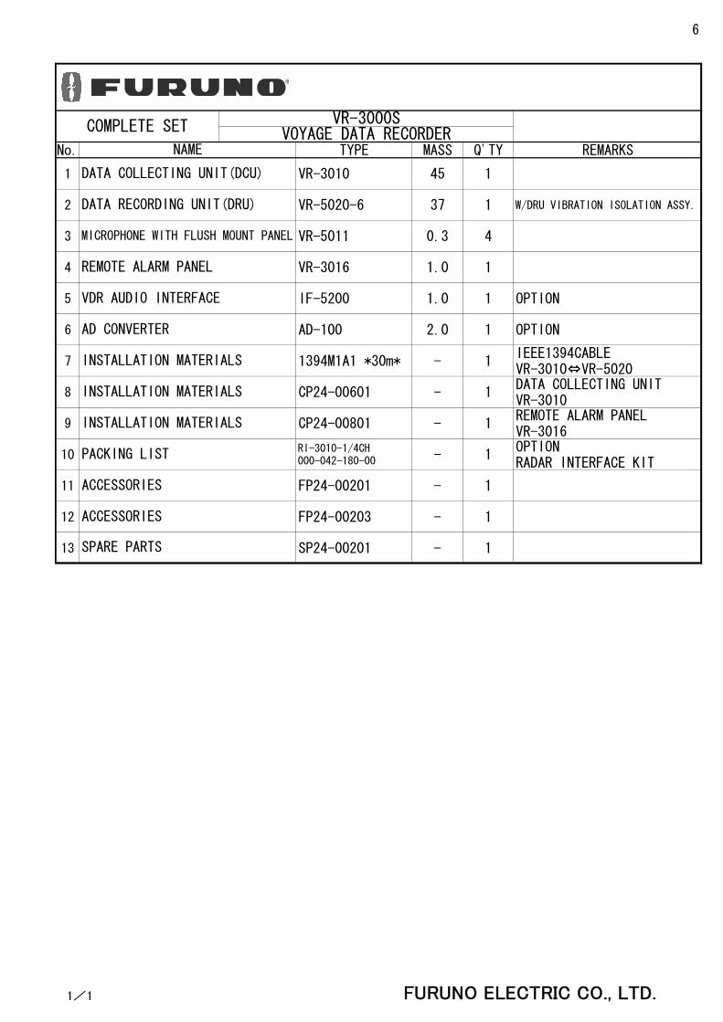
No. TYPE MASS Q'TY REMARKS
1 VR-3010 45 1
2 VR-5020-6 37 1 W/DRU VIBRATION ISOLATION ASSY.
3 VR-5011 0.3 4
4 VR-3016 1.0 1
5 IF-5200 1.0 1 OPTION
6 AD-100 2.0 1 OPTION
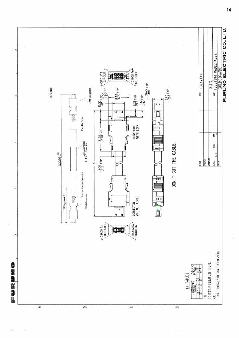
7 1394M1A1 *30m* - 1IEEE1394CABLEVR-3010⇔VR-5020
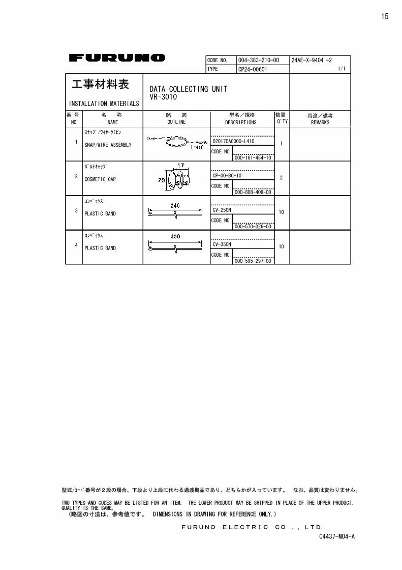
8 CP24-00601 - 1DATA COLLECTING UNITVR-3010
9 CP24-00801 - 1REMOTE ALARM PANELVR-3016
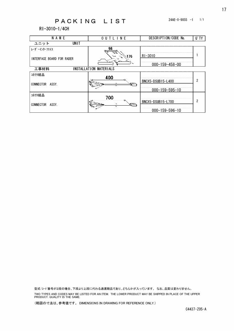
10RI-3010-1/4CH000-042-180-00 - 1
OPTIONRADAR INTERFACE KIT
11 FP24-00201 - 1
12 FP24-00203 - 1
13 SP24-00201 - 1
ACCESSORIES
SPARE PARTS
INSTALLATION MATERIALS
PACKING LIST
ACCESSORIES
INSTALLATION MATERIALS
INSTALLATION MATERIALS
NAME
REMOTE ALARM PANEL
DATA COLLECTING UNIT(DCU)
DATA RECORDING UNIT(DRU)
MICROPHONE WITH FLUSH MOUNT PANEL
VDR AUDIO INTERFACE
AD CONVERTER
COMPLETE SET VR-3000SVOYAGE DATA RECORDER
1/1 FURUNO ELECTRIC CO., LTD.
6
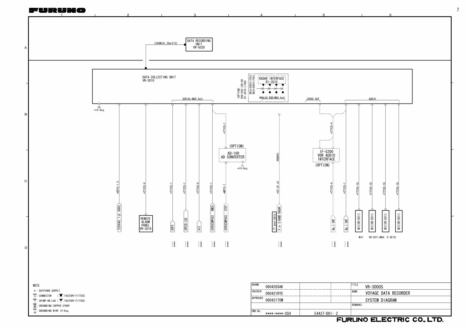
1 2
D
C
B
A
SYSTEM DIAGRAM
DRAWN
DWG.No.
TITLE
NAME
REMARKS
VOYAGE DATA RECORDER:FACTORY-FITTED)
:FACTORY-FITTED)
:CONNECTOR (
:CRIMP-ON LUG(
NOTE
:GROUNDING WIRE IV-8sq.
:GROUNDING COPPER STRAP
*:SHIPYARD SUPPLY
3 4 5 6
E4437-D01- 2
VR-3000S
SERIAL(MAX.8ch)
AIS
----
****
----
****
----
****
DGPS
----
****
*IV-8sq.
*TTYCS-1
*TTYCS-1
*TTYCS-1
*TTYCS-4
GYROCOMPASS:
NMEA
PANELVR-3016
REMOTEALARM
220
VAC
,1φ
,60
Hz
----
****
*MPYC-7
GYROCOMPASS:
STEP
----
****
Ifavailable
(RGBHV)
Xor
S-BAND
RADAR
*IV-8sq.
*TTYCS-1
*5C-2Vx5
*TTYCS-4
CHECKED
APPROVED
SPEEDLOG
DATA COLLECTING UNITVR-3010
RADAR INTERFACE
BNCx
5-DS
UB15
-L70
0x2
BNCx
5-DS
UB15
-L70
0x2
DATA RECORDINGUNIT
VR-5020
1394M1A1,30m(FIX)
ANALOG RGB(MAX.4ch)(OPTION)
RI-3010-1/4CH
000-042-180-00
060420SAK
060421RYE
060421TOM
****-****-SS4
RI-3010
*DPYC-1.5
(OPTION)
AD CONVERTERAD-100
AUDIO
MIC(VR-5011)
MIC(VR-5011)
MIC(VR-5011)
MIC(VR-5011)
VR-5011(MAX. 6 SETS)MIC
*TTYCS-1Q
*TTYCS-1Q
*TTYCS-1Q
*TTYCS-1Q
24VDC OUT
*TTYCS-4
*TTYCS-4
VDR AUDIOINTERFACE
IF-5200
****
----
No.1
VHF
No.1
VHF
----
****
(OPTION)
*TTYCS-1
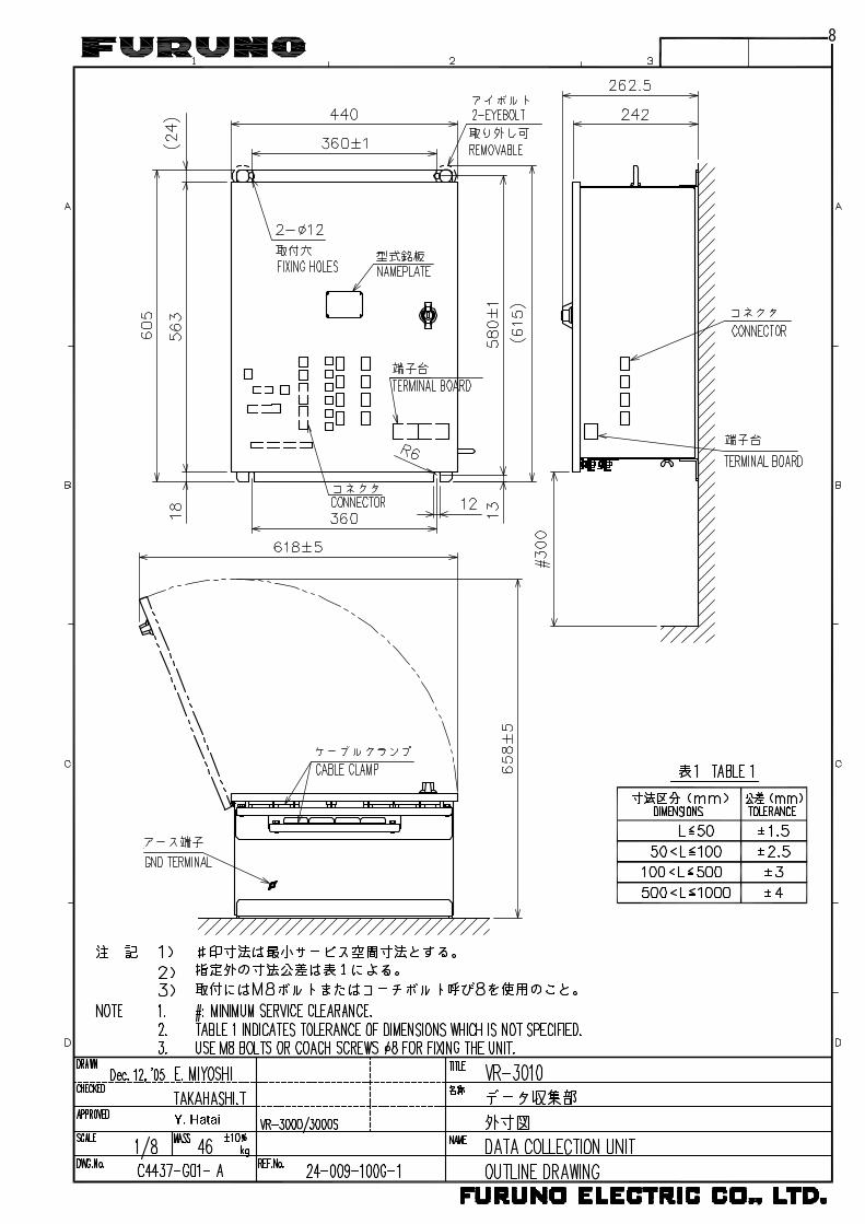
7
8

9

10
11

12

13
14
1394M1A1
CONNECTOR
WITHOUT LOCK
CONNECTOR
WITH LOCK
8.4±
0.1
IEEE1394 CABLE ASSY.
DON'T CUT THE CABLE.
15
DATA COLLECTING UNITVR-3010

16
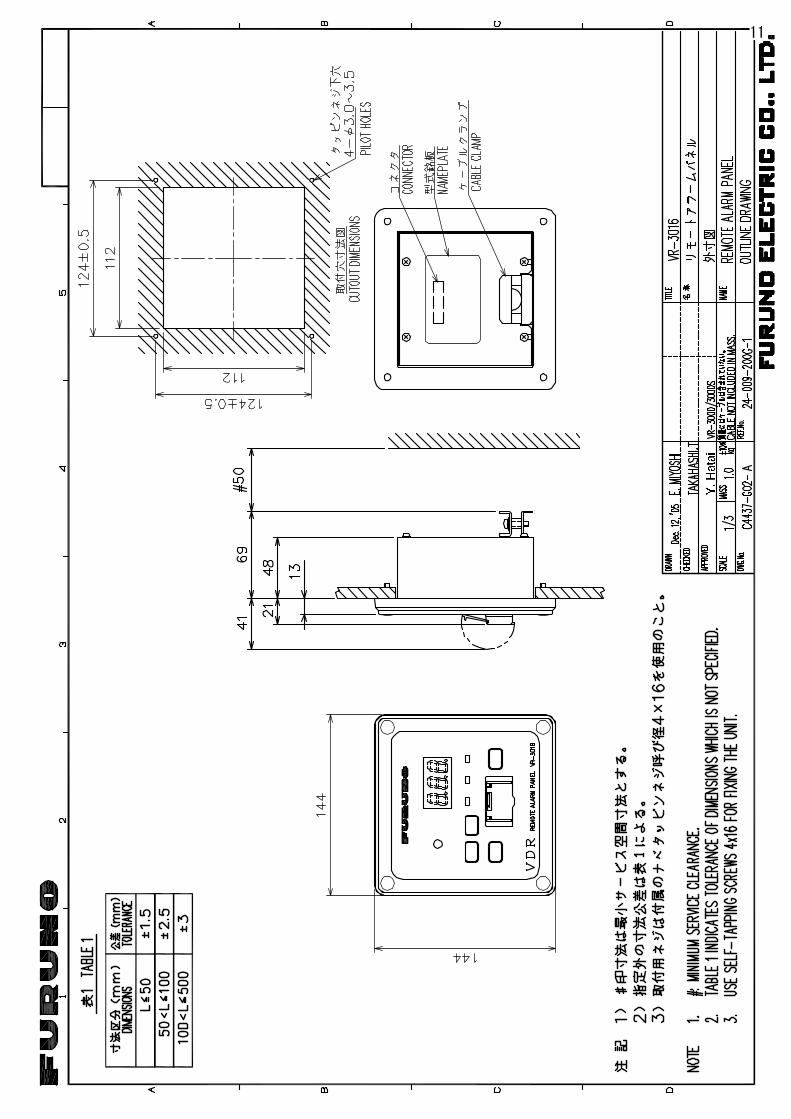
REMOTE ALARM PANELVR-3016
17

18

19

20
DATA COLLECTING UNITVR-3010
1 2 4 5 63
B
A
D
C
NAME
名称
TITLE
DWG No.
DRAWN
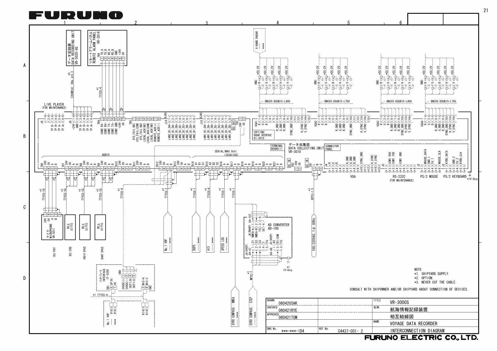
REF.No.INTERCONNECTION DIAGRAM
相互結線図
航海情報記録装置
VOYAGE DATA RECORDER
C4437-C01- 2
CONSULT WITH SHIPOWNER AND/OR SHIPYARD ABOUT CONNECTION OF DEVICES.
124V
124V
124V
124V
TB7
TB8
TB9
TB10
124V
TB11
4 2 3
OV A B
4 2 3
OV A B
4 2 3
OV A B
4 2 3
OV A B
4 2 3
OV A B
124V
TB6
4 2 3
OV A B
1 2 3 4 5 6
TB5
7 8
SYS_FAIL(COM)
SYS_FAIL(NC)
SYS_FAIL(NO)
LOCAL_ACK(COM)
LOCAL_ACK(NC)
LOCAL_ACK(NO)
REMOTE_ACK(+)
REMOTE_ACK(-)
1 2 3 4 5 6 7 8
LAN2_BI_DA+
LAN2_BI_DA-
LAN2_BI_DB+
LAN2_BI_DC-
LAN2_BI_DC+
LAN2_BI_DB-
LAN2_BI_DD-
LAN2_BI_DD+
RJ45
1 2 3 4 5 6 7 8
LAN1_BI_DA+
LAN1_BI_DA-
LAN1_BI_DB+
LAN1_BI_DC+
LAN1_BI_DC-
LAN1_BI_DB-
LAN1_BI_DD+
LAN1_BI_DD-
RJ45
1 224V 0VTB
3
1 2 3 4
TB4
5 6 7OV
+24V
COM2
RX-
COM2
RX+
COM2
TX-
COM2
TX+
COM2
GND
1 2 3 4 5 6
GNDJ8
+24V J1
4
J10
DCOUT
TPB-
TPB+
TPA-
TPA+
1 2 3 4 5 6
TPB-
TPB+
TPA-
TPA+J6
(FOR MAINTENANCE)LIVE PLAYER
AUDIOSERIAL(MAX.8ch)
TTYCS-1Q
CHARTSPAC
E
RADI
OSPACE
BCCST
BD
BCCPORT
同上
DITTO
同上
DITTO
*1
*1
*1
*1
TTYCS-1Q
TTYCS-1Q
TTYCS-1Q
同上
DITTO
マイク
VR-5011
MICROPHONE
BAOV
324 5
24V
1
PP P P PP P PTTYCS-4*1
GND
+24V
OV
7
RD_B
RD_A
TD_B
TD_A
VR-3
016
リモートアラームパネル
REMO
TEAL
ARM
PANEL
65
TB4
4321P P P
1394M1A1
VR-
5020-
6G
30m,φ
6.3
*3デ
ータ
記録
器DAT
AREC
ORDI
NGUN
IT
NOTE*1. SHIPYARD SUPPLY.
*3. NEVER CUT THE CABLE.*2. OPTION.
*IV-8sq.VGA
1 2 3 4 5 6 87 9 10
11
12
13
14
15
H_SYNC
V_SYNC
R BG R_GND
G_GND
B_GND
SYNC_GND
RS-232C
1 2 3 4 5 6 87 9
COM1RXD
COM1TXD
COM1GND
PS/2 MOUSE
1 2 3 4 5 6
MOUSE_DATA
GND_1
5V_1
MOUSE_CLK
1 2 3 4 5 6
KYBD_DATA
KYBD_CLK
GND_2
5V_2
CONNECTORPANEL
(FOR MAINTENANCE)
J4
J3
J2
J5
PS/2 KEYBOARD
1 2 3
TB1 L N G
1 2
TB2 24
V0V
DCIN
ACIN
DATA COLLECTING UNITデータ収集部
VR-3010
*1
TB12
TB13
1 2 3
TB14
A1 B1 G1
1 2 3
TB15
1 2
TB16
A2 B2 G2 A B
1 2A B
1 2A B
1 2A B
1 2A B
1 2A B
TB17
TB18
TB19
TB20
TB21
2 3A B
124V
4OV
BOARD(1)TERMINAL
(IEC61162)
*1
*1
TTYCS-1
DGPS
*1
TTYCS-1
*1
TTYCS-1
2 3A B
124V
4OV
----:****
----:****
GYRO
COMPASS:NMEA
J6(NH4P) AD CONVERTER
AD-100
64-107
4321
FG
SG
NMEA-A
NMEA-B
J4(VH5P)
*1IV-8sq.
J5(VH3P)
64-48
64-47 54321 321
FG
S1
S2
S3
T FG
R2
R1/COM
----:****
GYRO
COMPASS:STEP
*1
----:****
----:****
AIS
TTYCS-4
100/
220VA
C,1φ
,60H
z
MPYC-7
VR-3000SCHECKED
APPROVED
SPEEDLOG
1 2 3 4 5 6 87 9 10
11
12
13
14
15
H_SYNC
V_SYNCR G B
R_GND
G_GND
B_GND
SYNC_GND
VGA1
****
----
*5C-2V
*5C-2V
*5C-2V
*5C-2V
X-BAND
RADAR
BNC R G B H V
BNCX5-DSUB15-L400
*5C-2V
RI-3010RADAR INTERFACE(OPTION)
1 2 3
R G B
*5C-2V
*5C-2V
*5C-2V
*5C-2V
BNC R G B H V
*5C-2V
6 87R_GND
G_GND
B_GND
10
SYNC_GND
13
14
H_SYNC
V_SYNC
1 2 3 4 5 6 87 9 10
11
12
13
14
15
H_SYNC
V_SYNCR G B
R_GND
G_GND
B_GND
SYNC_GND
VGA2
*5C-2V
*5C-2V
*5C-2V
*5C-2V
BNC R G B H V
*5C-2V
BNCX5-DSUB15-L700
1 2 3
R G B
*5C-2V
*5C-2V
*5C-2V
*5C-2V
BNC R G B H V
*5C-2V
BNCX5-DSUB15-L400
VGA3
6 87R_GND
G_GND
B_GND
10
SYNC_GND
13
14
H_SYNC
V_SYNC
VGA4
BNCX5-DSUB15-L700
DPYC-1.5
060420SAK
060421RYE
060421TOM
***-***-ID4
*1TTYCS-1
----:****
No.1
VHF
No.1
VHF
CN2
OVSP(H)
15
*1 TTYCS-4
MIC-OUT_H
MIC-OUT_C
SP-OUT_C
SP-OUT_H
****
----
TTYCS-4*1
CN9
24VDC(-)
24VDC(+)21
MIC-C
MIC-H
43
IF-5200
INTERFACE
インターフェース
OUT1(C)
OUT1(H)54
CN1
21

S-V
DR
(VR
-3000S) B
LO
CK D
IAG
RA
M F
OR
RA
DA
R

S-V
DR
(VR
-3000S)
BLO
CK D
IAG
RA
M F
OR
AIS

A-1Wiring method of S-VDR RADAR-CONNECTION Ver.
( RADAR video signal input Version : Minimum input situation )
VGA1~VGA4RADAR image input connector
(DSUB-15pin)
IEEE-1394 CABLE <===> VR-5020
TB14 : GPS Signal inputIt's necessary to input GPS-SIGNAL
into this terminal.
TB4 : RAP Connection <===> VR-3016
TB16~21 : IEC-61162 Signal input
<=== Input demand equipment
TB6~11 : VDR-MIC inpitThe numbers of microphones
change according to thearrangement and the size of W/H.---------------------------
TB12,13VHF sound of GMDSS equipment is
inputted.( Input of one set is indispensable )
Power supply input terminal100-230VAC,1φ,60/50Hz
or24VDC
( Either is chosen )
Wiring_method_of_VR-3000S
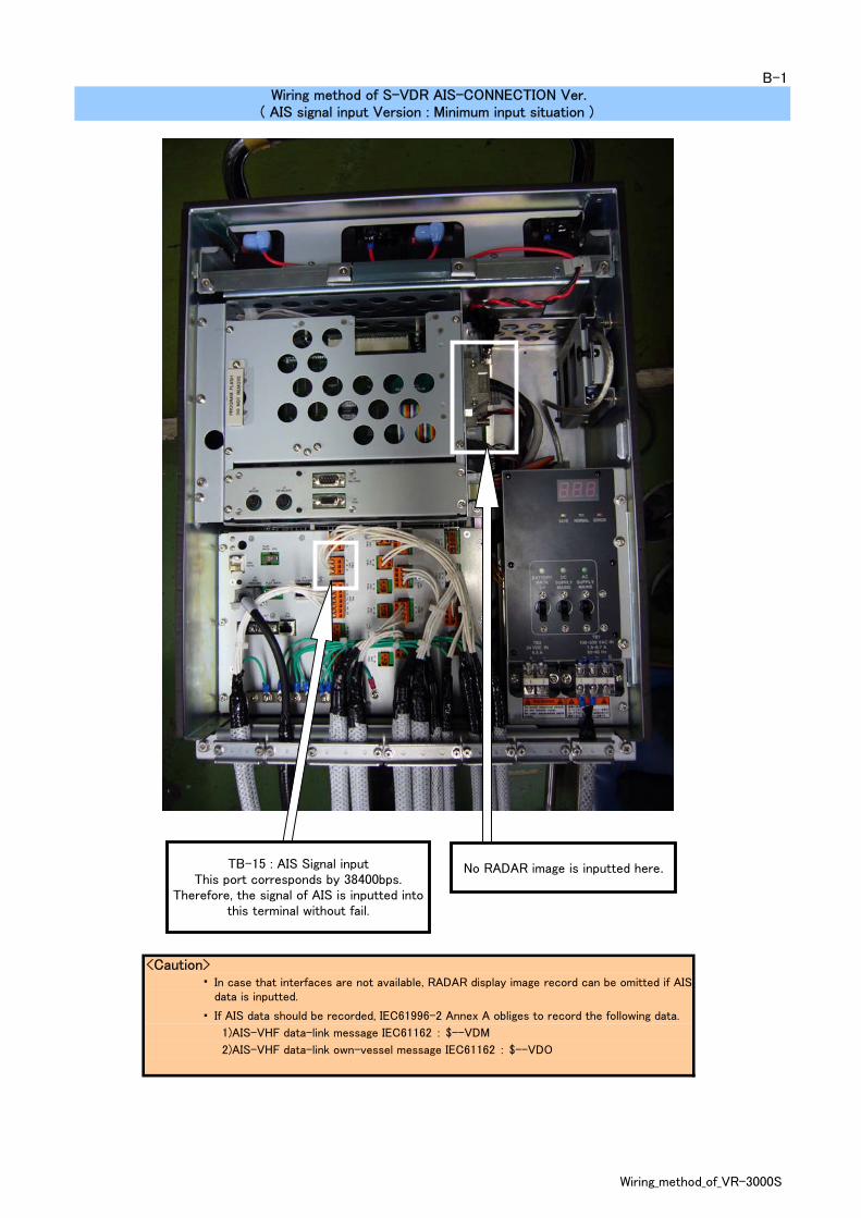
<Caution>・
・ If AIS data should be recorded, IEC61996-2 Annex A obliges to record the following data.
1)AIS-VHF data-link message IEC61162 : $--VDM
2)AIS-VHF data-link own-vessel message IEC61162 : $--VDO
B-1
In case that interfaces are not available, RADAR display image record can be omitted if AISdata is inputted.
Wiring method of S-VDR AIS-CONNECTION Ver.( AIS signal input Version : Minimum input situation )
TB-15 : AIS Signal inputThis port corresponds by 38400bps.
Therefore, the signal of AIS is inputted intothis terminal without fail.
No RADAR image is inputted here.
Wiring_method_of_VR-3000S

<Caution>RADAR-INTERFACE-BOARD : RI -3010 (000-159-458-00),RGBHV CABLE : BNCX5-DSUB15-L400 (000-158-870-00) andBNCX5-DSUB15-L700 (000-158-871-00) are not contained in thestandard composition of SVDR.
A : BNCX5-DSUB15-L400 (Cable length : 400mm)B : BNCX5-DSUB15-L700 (Cable length : 700mm) ・The 400mm cable wires right-hand side. And the 700mm cable wires left-hand side. ・When connecting with one RADAR, the suitable cable length can be chosen.
Wiring method of BNCX5-DSUB15:CONNECTOR-ASSY
Please follow the request of each Vessel concerning the aboveequipments arrangement.
( RADAR video signal input cable )
C-1
BA
G-LINE of CABLE-A is connected byusing the terminal panel's fixing screw.G-LINE of CABLE-B is connected with
Earth-bar.
BNC-CONNECTOR must be insulatedwith vinyl insulation tape etc.
The cable is fixed byPLASTIC-BAND using ventilation holes.
It lets CABLE-CLIP pass.Two or more cables are bound together with PLASTIC-
BAND, letting them passing through CABLE-CLIP.
Wiring_method_of_VR-3000S
C-2
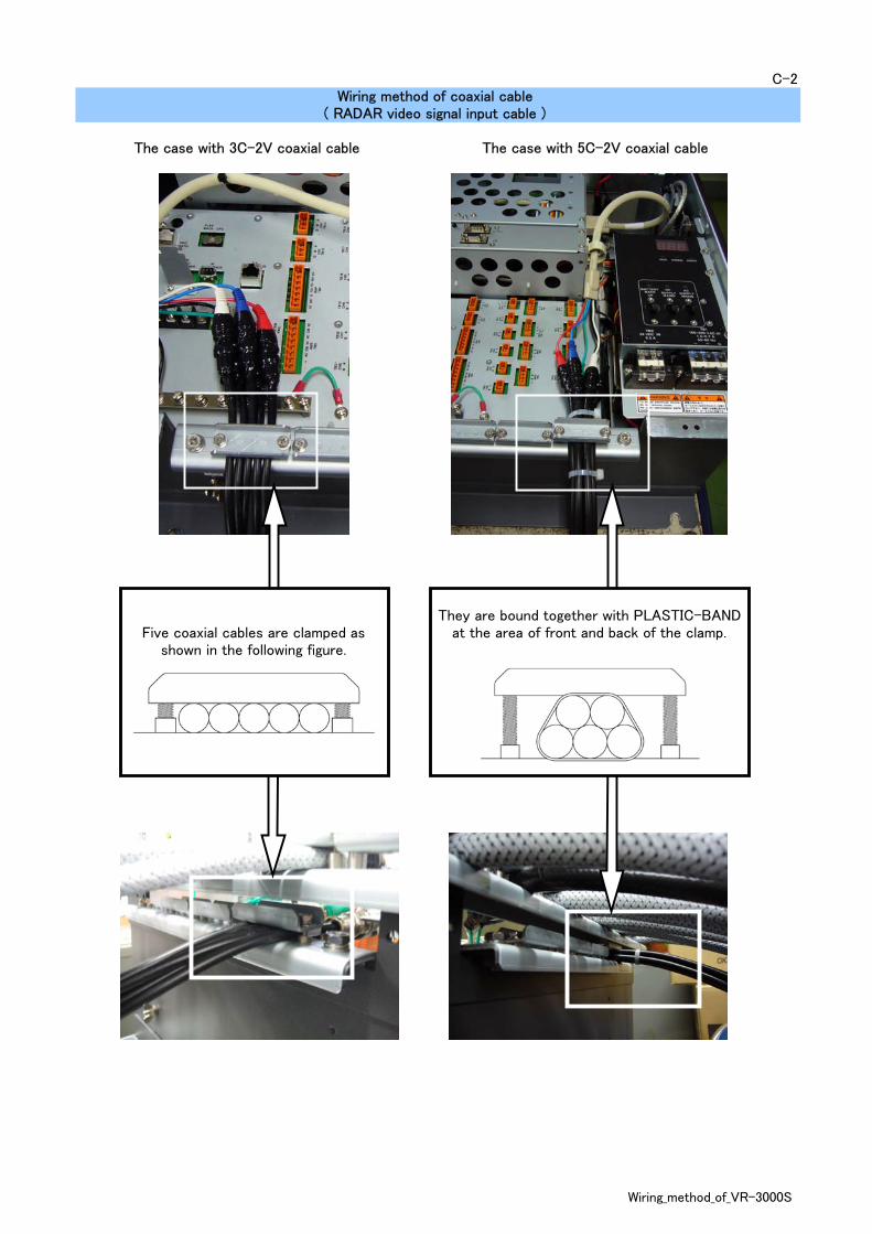
( RADAR video signal input cable )Wiring method of coaxial cable
The case with 3C-2V coaxial cable The case with 5C-2V coaxial cable
Five coaxial cables are clamped asshown in the following figure.
They are bound together with PLASTIC-BANDat the area of front and back of the clamp.
Wiring_method_of_VR-3000S

・ The Cable-Armor portion to be clamped.・ The shield to be connected to a ground bar.・ Use a green color cable as the ground cable.
・
・
・
D-1
Wago-Connector should be connected to theterminal stand after removing the chip to avoiddamage of the terminal stand.
Wiring method of IEEE-1394 cable : VR-3010 SIDE( Data transmission cable : Between VR-3010 and VR-5020 )
Wiring method of Shielded cable cable and Ground
To be inserted in terminal stand certainly aftercompleting connection with the connector chip.The processing part of the cable to be protected bya vinyl tape.
( The size to be 1.25sq or more )
Make sure that the cable is tightly connected to the portwith the guide of PLASTIC-BAND.
Wiring_method_of_VR-3000S

Wiring method of External wiring curvature( VR-3010 )
E-1
Bend radius of150mm
Clunping point300mm or more
Refer to the drawing to have some spacearound the equipment and allow the door
of the equipment open wide.
Wiring_method_of_VR-3000S

・ The Cable-Armor portion to be clamped.・
・ Use a green color cable as the ground cable.
・
・
・
・
( VR-3016 )
( The size to be 1.25sq or more )Wago-Connector should be connected to theterminal stand after removing the chip to avoiddamage of the terminal stand.
If the spacer "A" does not work when the space aretoo wide (as shown in the above) the spacer is notnecessary.The processing part of the cable to be protected bya vinyl tape.
The shielded cable is connected to the shield screwof the back panel.
To be inserted in terminal stand certainly aftercompleting connection with the connector chip.
Wiring method of REMOTE ALARM PANELF-1
A
A
Wiring_method_of_VR-3000S
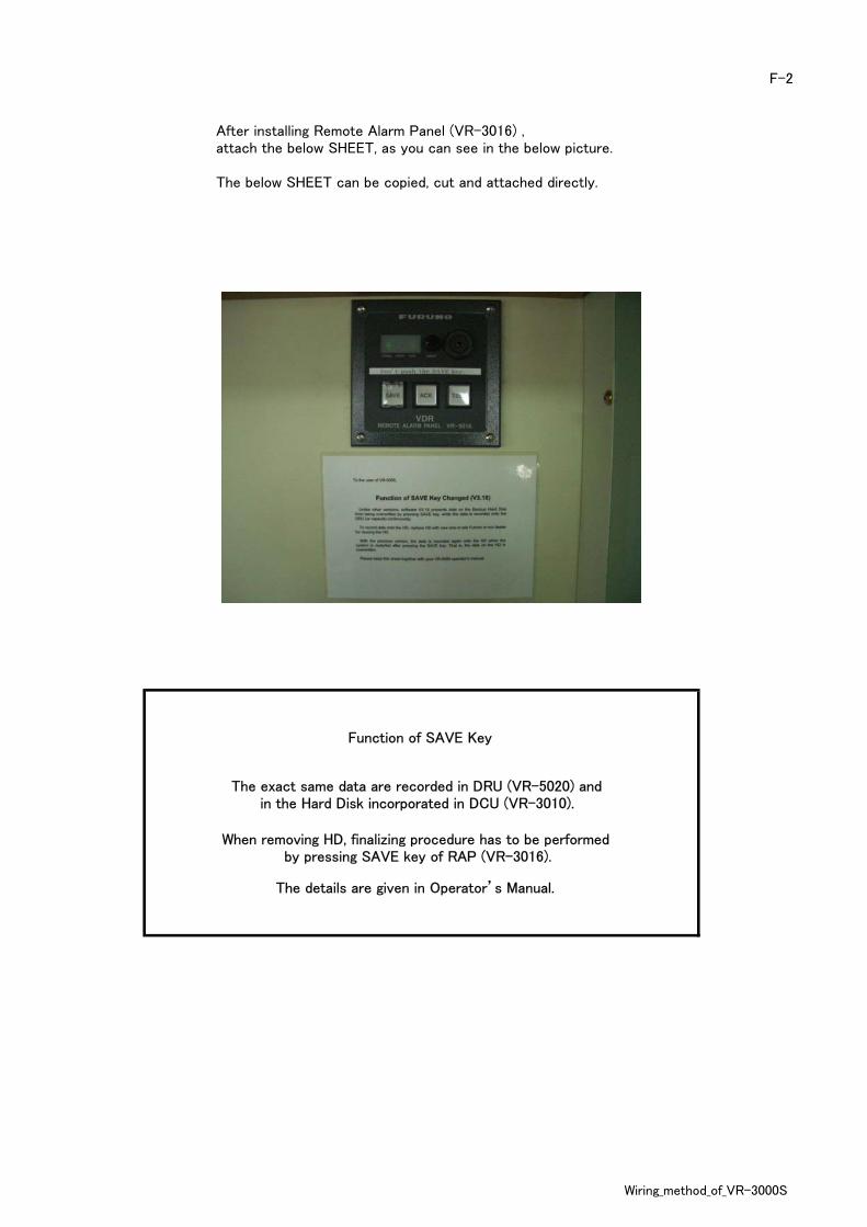
The exact same data are recorded in DRU (VR-5020) andin the Hard Disk incorporated in DCU (VR-3010).
When removing HD, finalizing procedure has to be performedby pressing SAVE key of RAP (VR-3016).
The details are given in Operator’s Manual.
Function of SAVE Key
F-2
After installing Remote Alarm Panel (VR-3016) ,attach the below SHEET, as you can see in the below picture.
The below SHEET can be copied, cut and attached directly.
Wiring_method_of_VR-3000S

・
・ Connection of a shield is indispensable.
・ The processing part of the cable is protected by a vinyl tape.
・
・ Waterproofing processing of the part of "A" is carried out. Waterproofing putty or silicone is used.
G-1Wiring method of MICROPHONE
( VR-5011 + VR-5012 ) : Provisional
Refer to the "Processing method of multi-core cable end"for processing of a cable.
( VR-5011 )
Wiring method of MICROPHONE
When equipping Open-wing with a microphone, a waterproofing box(VR-5012) and a microphone (VR-5011) are combined.
A
Wiring_method_of_VR-3000S

・
・
・
・
・ There is no coat for the DCU(VR-3010) side PLUG.
・
H-1
Let Cap-nut, Teflon Washer and Gum Bushinto the cable in advance.
Since the cable configurations are different atDCU (VR-3010) side and DRU (VR-5020) side,take care of handling the cable.
DRU(VR-5020) side PLUG is delivered with awaterproofing coat.Never remove this coat until the last minuteto connect to DRU.
Never damage the cable or plug whenremoving the waterproofing coat.
Wiring method of IEEE-1394 cable : VR-5020 SIDE( Data transmission cable : Between VR-3010 and VR-5020 )
Never cut this cable.
DRU-SIDE
DCU-SIDE
Wiring_method_of_VR-3000S
・
・
・
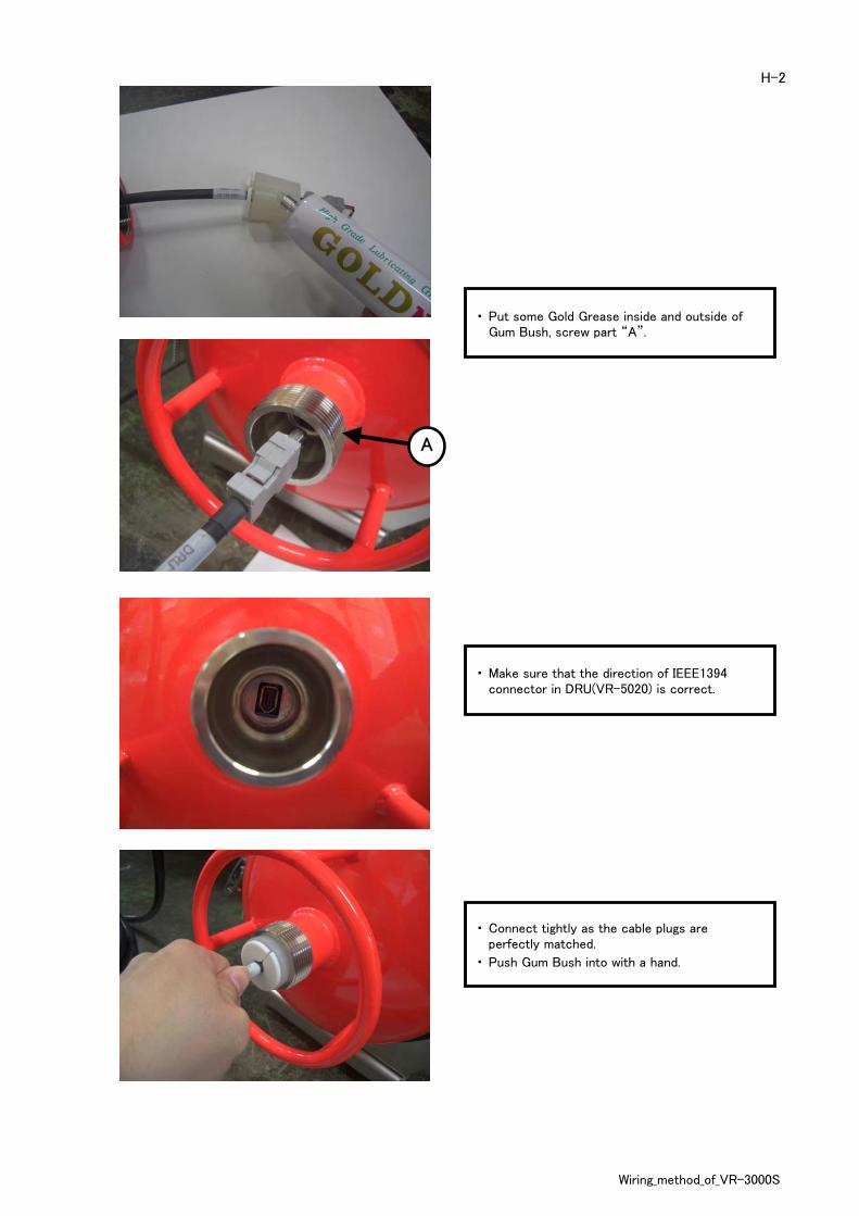
・ Push Gum Bush into with a hand.
Put some Gold Grease inside and outside ofGum Bush, screw part “A”.
Connect tightly as the cable plugs areperfectly matched.
Make sure that the direction of IEEE1394connector in DRU(VR-5020) is correct.
H-2
A
Wiring_method_of_VR-3000S

・
・
・
・ Waterproof perfectly with silicon (KE45).
The cap cannot be tightened up to theend of the thread.
Apply enough silicon (KE45) to the surface ofTeflon Washer and penetration part of cable.
The DRU cap nut is tightened until onethread or two threads are left visible.
H-3
Wiring_method_of_VR-3000S
・
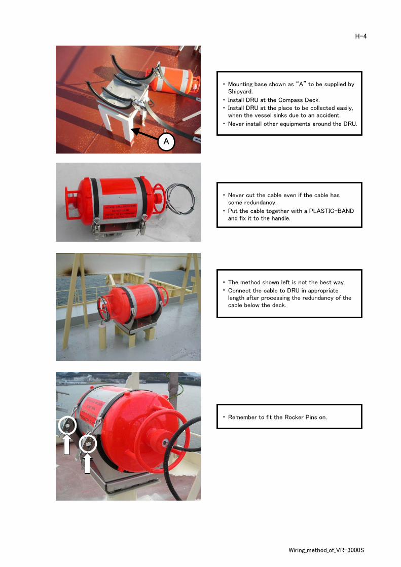
・ Install DRU at the Compass Deck.
・
・ Never install other equipments around the DRU.
・
・
・ The method shown left is not the best way.
・
・ Remember to fit the Rocker Pins on.
Connect the cable to DRU in appropriatelength after processing the redundancy of thecable below the deck.
Mounting base shown as “A” to be supplied byShipyard.
Install DRU at the place to be collected easily,when the vessel sinks due to an accident.
Put the cable together with a PLASTIC-BANDand fix it to the handle.
Never cut the cable even if the cable hassome redundancy.
H-4
A
Wiring_method_of_VR-3000S

・
・
・
I-1
( RADAR video signal input cable )
Let Clamp-nut, Washer, and Gasket into acoaxial cable in advance.
The coaxial shield and an insulator to bestripped 3mm from the tip.
The cable outer cover sheath to be stripped7mm.
Processing method of BNC connector
Clamp nut
Washer
Gasket
Clamp
Center pin
Outer shell
7mm
3mm
Wiring_method_of_VR-3000S

・
・
・ Center-pin is inserted into a core cable.And solder is carried out.
・ Make sure that Center-pin does not separate.
・ Outer-shell is put firmly.
・ Completion
I-2
Clamp is set and a coaxial shield is turned up.
The overflowing coaxial shield to be cut to aneven length.
Wiring_method_of_VR-3000S

・ Prepare the cable to skin.
・ Outside armor is stripped.
・
・
J-1
The vinyl sheath to be stripped from a 10mmplace from the end of outside armor.
The shield is divided and an inner cable ispulled out.
Processing method of multi-core cable end
10mm
Wiring_method_of_VR-3000S

・ The internal insulator of a cable is cut.
・ The cutting length of an insulator is 10mm.
・ The shield is twisted.
・
・
・
J-2
Unnecessary shield and cables are connectedto an earth cable after being cut and soldered.
The connection point of a ground cable isinsulated by a vinyl tape.
The processing part of the cable is protectedby a vinyl tape.
Wiring_method_of_VR-3000S

・ The Wago terminal chip is removed.
・ The tips of cables are skinned by 8~10mm.
・
・ A cable is inserted and a clip tool is drawn out.
・
・ Completion
K-1
Cables are pulled out and make sure theconnection are correctly performed.
A clip tool is inserted in a Wago terminal chip,and a clip is opened.
Processing method of Wago connector
Wiring_method_of_VR-3000S


