Quick Installation Guide Fujitsu Technology Solutions GmbH, User Documentation, 33106 Paderborn, Germany • Email - [email protected]l Online - http://ts.fujitsu.com/support All hardware and software names used are trademarks of their respective manufacturers. 590-1057-640A installation 4 KVM s4 Switch KVM s4-0812 | KVM s4-1622 | KVM s4-3242 The following instructions will help you install and use your switch easily. Should you require further assistance, please consult your installer/user guide. 1 Connecting the local port Connect your VGA monitor and USB keyboard and mouse cables into the appropriate ports on the KVM s4 switch. 2 Connecting a CAT 5 adapter cable to the KVM s4 switch Connect one end of a CAT 5 cable (4-pair, up to 150 ft/45 m) into an available numbered port on the rear of your switch. Connect the other end into the RJ-45 connector of the CAT 5 adapter cable. 3 Connecting a target device to a CAT 5 adapter cable Connect a CAT 5 adapter cable into the appropriate port on the back of a target device. Repeat steps 2 and 3 for all target devices you want to connect. 4 Connecting network users Connect a customer supplied CAT 5 cable from the Ethernet network into a LAN port on the back of the switch. Network users will access the switch through this port. 5 Connecting to an external modem (optional) The switch may also be accessed using an ITU V.92, V.90 or V.24-compatible modem. Connect one end of a CAT 5 cable into the MODEM port on the switch. Connect the other end into the CAT 5 to DB-9 (male) adapter, which then connects into the appropriate port on the back of the modem. KVM s4 switch configuration Telephone network Target devices 2 1 KVM s4 Switch (KVM s4-3242 shown) Ethernet Modem CAT 5 Adapters 3 4 Local USB Connections
Transcript
Quick Installation Guide
Fujitsu Technology Solutions GmbH, User Documentation, 33106 Paderborn, Germany • Email - [email protected] l Online - http://ts.fujitsu.com/supportAll hardware and software names used are trademarks of their respective manufacturers. 590-1057-640A
1 Connecting the local portConnect your VGA monitor and USB keyboard and
mouse cables into the appropriate ports on the KVM
s4 switch.
2 Connecting a CAT 5 adapter cable to the KVM s4 switchConnect one end of a CAT 5 cable (4-pair, up to 150 ft/45 m)
into an available numbered port on the rear of
your switch. Connect the other end into the RJ-45
connector of the CAT 5 adapter cable.
3 Connecting a target device to a CAT 5 adapter cableConnect a CAT 5 adapter cable into the appropriate
port on the back of a target device. Repeat steps 2
and 3 for all target devices you want to connect.
4 Connecting network usersConnect a customer supplied CAT 5 cable from the
Ethernet network into a LAN port on the back of
the switch. Network users will access the switch
through this port.
5 Connecting to an external modem (optional)The switch may also be accessed using an ITU V.92,
V.90 or V.24-compatible modem. Connect one end of
a CAT 5 cable into the MODEM port on the switch.
Connect the other end into the CAT 5 to DB-9 (male)
adapter, which then connects into the appropriate
port on the back of the modem.
KVM s4 switch configuration
Telephone network
Target devices
21
KVM s4 Switch (KVM s4-3242 shown)
Ethernet Modem
CAT 5 Adapters
3
4
Local USB Connections
Quick Installation Guide
Fujitsu Technology Solutions GmbH, User Documentation, 33106 Paderborn, Germany • Email - [email protected] l Online - http://ts.fujitsu.com/supportAll hardware and software names used are trademarks of their respective manufacturers. 590-1057-640A
6 Connecting a supported PDU to the switch (optional)Connect one end of the RJ-45 cable supplied with
the Power Distribution Unit (PDU) into the PDU1 port
on the switch. Using the supplied RJ-45 adapter,
connect the other end into the PDU. Connect the
power cords from the target devices into the PDU.
Connect the PDU into an appropriate AC wall outlet.
Repeat this procedure for the PDU2 port to connect
a second PDU, if desired.
7 Connecting local virtual media or smart cards (optional)Connect virtual media devices or smart card readers
to any of the USB ports on the switch. To open a virtual
media session with a target device, the target device
must first be connected to the switch using a virtual
media capable adapter cable. To map a smart card
with a target device, the target device must first be
connected to the switch using a smart card capable
adapter cable.
8 Turning on target devices and connecting power to the switchTurn on each target device, then locate the power
cords that came with the switch. Connect one end
into the power socket on the rear of the switch and
connect the other end into an appropriate AC wall
outlet. Repeat this step for the second power cord
to provide redundant internal power supplies.
NOTE: Plugging the redundant power supplies into
separate branch circuits provides additional redun-
dancy in the event one external AC power source
loses power.
NOTE: The network settings can be configured via
the local port using the local user interface or from
a VT100 terminal emulator connected to the serial
setup port.
Adapter configuration
Target devices
67
KVM s4 Switch (KVM s4-3242 shown)
PDU
External media device
8
The following instructions will help you install
and use your switch easily.
Should you require further assistance, please
consult your installer/user guide.
Quick Installation Guide
Fujitsu Technology Solutions GmbH, User Documentation, 33106 Paderborn, Germany • Email - [email protected] l Online - http://ts.fujitsu.com/supportAll hardware and software names used are trademarks of their respective manufacturers. 590-1057-640A
Fujitsu Technology Solutions GmbH, User Documentation, 33106 Paderborn, Germany • Email - [email protected] l Online - http://ts.fujitsu.com/supportAll hardware and software names used are trademarks of their respective manufacturers. 590-1057-640A
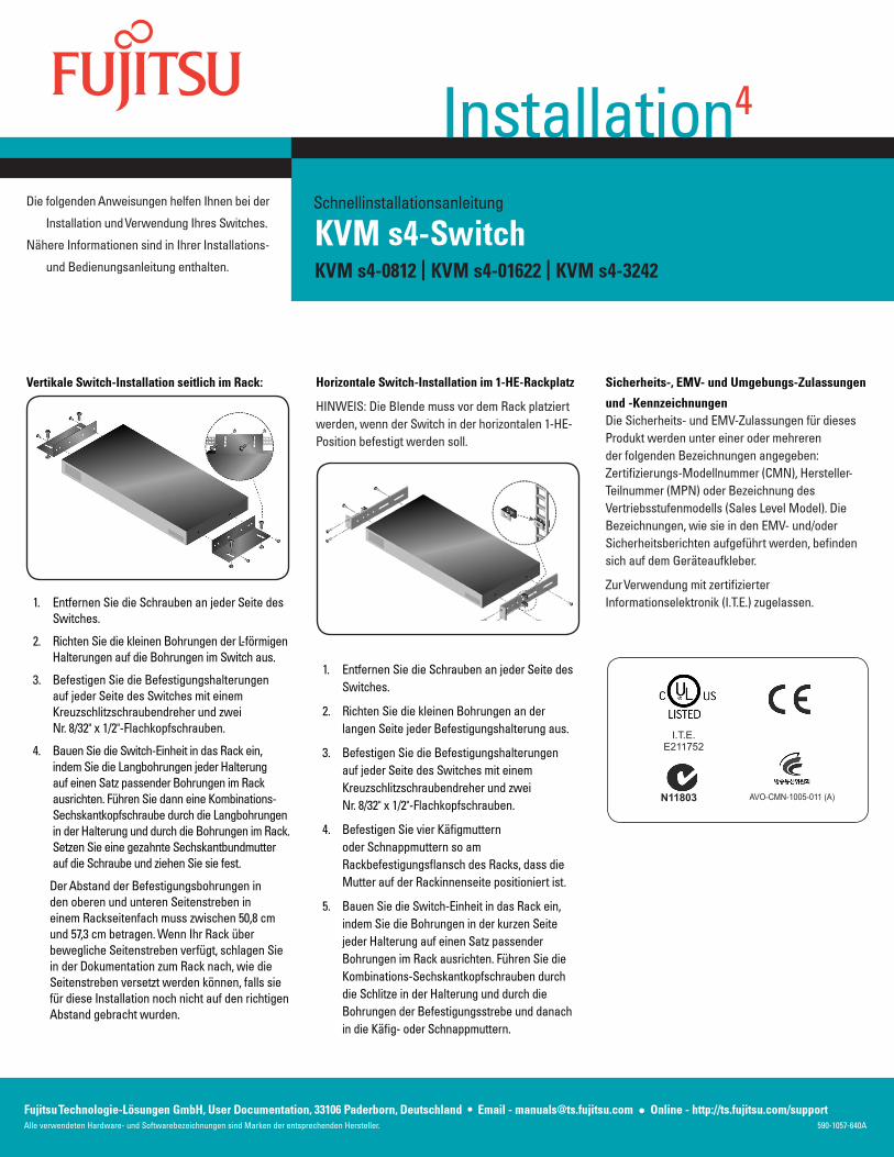
Installing the switch vertically in the side of a rack:
Remove the screws on each side of the switch.1.
Line up the small holes of the L-shaped brackets 2.
with the screw holes in the switch.
With a Phillips screwdriver, fasten the mounting 3.
brackets to the switch using two 8/32-inch x 1/2-
inch pan-head screws on each side.
Mount the switch assembly to the rack by 4.
matching the long slots on each bracket to a set
of holes on the rack. Next, insert a combination
hex-head screw through the slots in the bracket
and the holes in the rack. Cap the screw with a
hex serrated flange nut and tighten.
The mounting holes on the upper and lower
side braces in a rack side compartment must be
between 50.8-cm (20.0-in.) and 57.3-cm (22.6-in.)
apart. If the rack has movable side braces, refer
to the rack documentation for information about
relocating side braces if they are not already
spaced for this installation.
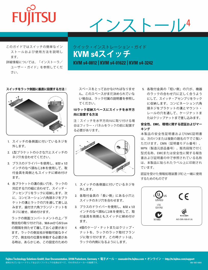
Installing the switch horizontally in the 1-U rack
mounting space
NOTE: The filler panel must be placed in front of the
rack when the switch is mounted in the horizontal
1-U orientation.
Remove the screws on each side of the switch.1.
Line up the small holes in the long side of each 2.
mounting bracket.
With a Phillips screwdriver, fasten the mounting 3.
brackets to the switch using two 8/32-inch x 1/2-
inch pan-head screws on each side.
Attach four cage nuts or clip nuts to the rack 4.
mounting flange of the rack so that the nut is
positioned on the inside of the rack.
Mount the switch assembly to the rack by 5.
matching the holes in the short side of each
mounting bracket to a set of matching holes
on the rack. Insert the combination hex-head
screws through the slots in the mounting bracket
and the holes in the mounting rail, then into the
cage nuts or clip nuts.
Safety, EMC and Environmental Approvals and
Markings
Safety certifications and EMC certifications for
this product are obtained under one or more of the
following designations: CMN (Certification Model
Number), MPN (Manufacturer’s Part Number) or
Sales Level Model designation. Designations that
are referenced in the EMC and/or safety reports
and certificates are printed on the label applied to
this product.
For use with Listed Information Technology Equip-
ment (I.T.E.).
I.T.E.E211752
N11803 AVO-CMN-1005-011 (A)
Schnellinstallationsanleitung
Fujitsu Technologie-Lösungen GmbH, User Documentation, 33106 Paderborn, Deutschland • Email - [email protected] l Online - http://ts.fujitsu.com/supportAlle verwendeten Hardware- und Softwarebezeichnungen sind Marken der entsprechenden Hersteller. 590-1057-640A
1 Anschließen des lokalen PortsSchließen Sie einen VGA-Monitor und USB-Tastatur- und Mauskabel an die entsprechenden Ports des KVM s4-Switches an.
2 Anschließen eines CAT 5-Adapterkabels an den KVM s4-SwitchSchließen Sie ein Ende eines CAT 5-Kabels (4-paarig, bis zu 45 m) an einen nummerierten Port auf der Rückseite des Switches an. Schließen Sie das andere Ende am RJ-45-Anschluss des CAT 5-Adapterkabels an.
3 Anschließen des Zielgeräts an ein CAT 5-AdapterkabelSchließen Sie das CAT 5-Adapterkabel an den entsprechenden Port an der Rückseite des Zielgeräts an. Wiederholen Sie die Schritte 2 und 3 für alle Zielgeräte, die angeschlossen werden sollen.
4 Anschließen von Netzwerk-BenutzernSchließen Sie eines der CAT 5-Kabel (im Lieferumfang enthalten) des Ethernet-Netzwerks an einen LAN-Port an der Rückseite des Switches an. Netzwerk-Benutzer greifen über diesen Port auf den Switch zu.
5 An ein externes Modem anschließen (optional)Auf den Switch kann auch über ein ITU V.92-, V.90- oder V.24-kompatibles Modem zugegriffen werden. Schließen Sie ein Ende eines CAT 5-Kabels an den MODEM-Port des Switches an. Schließen Sie das andere Ende am im Lieferumfang enthaltenen CAT 5-auf-DB-9-Adapterstecker an, der dann an den entsprechenden Port an der Modemrückseite angeschlossen wird.
Konfiguration des KVM s4-Switches
Telefonnetz
Zielgeräte
21
KVM s4-Switch (KVM S4-3242 abgebildet)
Ethernet Modem
CAT 5-Adapter
3
4
Lokale USB-Verbindungen
Schnellinstallationsanleitung
Fujitsu Technologie-Lösungen GmbH, User Documentation, 33106 Paderborn, Deutschland • Email - [email protected] l Online - http://ts.fujitsu.com/supportAlle verwendeten Hardware- und Softwarebezeichnungen sind Marken der entsprechenden Hersteller. 590-1057-640A
6 Anschließen einer unterstützten PDU an einen Switch anschließen (optional)Schließen Sie ein Ende des RJ-45-Kabels, das im Lieferumfang der Stromverteilungseinheit (Power Distribution Unit, PDU) enthalten ist, an den PDU1-Port des Switches an. Schließen Sie unter Verwendung des RJ-45-Adapters, der im Lieferumfang der PDU enthalten ist, das andere Ende des Kabels an PDU an. Schließen Sie die Netzkabel der Zielgeräte an die PDU an. Schließen Sie die PDU an eine geeignete Netzsteckdose mit Wechselstrom an. Wiederholen Sie diesen Vorgang für den PDU2-Port, um bei Bedarf eine zweite PDU anzuschließen.
7 Anschließen von lokaler Virtual Media oder Smartcards (optional)Schließen Sie Virtual Media-Geräte oder Smartcard-Lesegeräte an einen der USB-Ports am Switch an. Um eine Virtual Media-Sitzung mit einem Zielgerät zu öffnen, muss das Zielgerät zuerst mit einem Virtual Media-fähigen Kabel an die Einheit angeschlossen werden. Wenn eine Smartcard einem Zielgerät zugeordnet werden soll, muss das Zielgerät zunächst mithilfe eines Smartcard-fähigen Adapterkabels an den Switch angeschlossen werden.
8 Zielgeräte einschalten und den Switch mit Strom versorgenSchalten Sie alle Zielgeräte ein und legen Sie die Stromkabel bereit, das im Lieferumfang des Switches enthalten ist. Schließen Sie das eine Ende des Netzkabels an die Steckdose auf der Rückseite des Switches und das andere Ende an eine geeignete Netzstromsteckdose an. Wiederholen Sie diesen Schritt für das zweite Netzkabel, um eine redundante interne Stromversorgung zu schaffen.
HINWEIS: Der Anschluss der Redundanz-Stromversorgungen an voneinander unabhängige Abzweigleitungen sorgt für zusätzliche Redundanz beim eventuellen Ausfall einer externen Wechselstromquelle.
HINWEIS: Die Netzwerkeinstellungen können mit der lokalen Benutzeroberfläche über einen lokalen Port oder von einem VT100 Terminal-Emulator, der an den seriellen Setup-Port angeschlossen ist, konfiguriert werden.
Adapterkonfiguration
Zielgeräte
67
KVM s4-Switch (KVM s4-3242 abgebildet)
PDU
Externes Mediengerät
8
Die folgenden Anweisungen helfen Ihnen bei der
Installation und Verwendung Ihres Switches.
Nähere Informationen sind in Ihrer Installations-
und Bedienungsanleitung enthalten.
Schnellinstallationsanleitung
Fujitsu Technologie-Lösungen GmbH, User Documentation, 33106 Paderborn, Deutschland • Email - [email protected] l Online - http://ts.fujitsu.com/supportAlle verwendeten Hardware- und Softwarebezeichnungen sind Marken der entsprechenden Hersteller. 590-1057-640A
GEFAHRElektrischer Strom in Strom-, Telefon- und Kommunikationskabeln ist gefährlich.
Zur Vermeidung von Elektroschock:
Während eines Gewitters keine Kabel • anschließen bzw. abziehen oder Installations- bzw. Wartungsarbeiten oder eine Neukonfi guration dieses Produkts vornehmen.
Alle Stromkabel müssen an eine • ordnungsgemäß verdrahtete und geerdete Steckdose angeschlossen werden.
Alle Geräte, die an dieses Produkt • angeschlossen werden, müssen an ordnungsgemäß verdrahtete Steckdosen angeschlossen werden.
Signalkabel möglichst nur mit einer Hand • anschließen oder abziehen.
Niemals Geräte einschalten, wenn Anzeichen • von Feuer, Wasser oder strukturellen Schäden bemerkt werden.
Die angeschlossenen Stromkabel, • Telekommunikationssysteme, Netzwerke und Modems nicht entfernen, wenn die Geräteabdeckungen geöffnet sind, es sei denn, Sie werden ausdrücklich in den Installations- und Konfi gurationsanleitungen dazu aufgefordert.
Kabel gemäß den folgenden Anweisungen • anschließen bzw. abziehen, wenn dieses Produkt oder die angeschlossenen Geräte installiert, bewegt wird oder wenn die Abdeckungen geöffnet werden.
Anschließen:
Alle Geräte AUSSCHALTEN.1.
Zuerst alle Kabel an die Geräte anschließen.2.
Die Signalkabel an die Anschlüsse 3. anschließen.
Die Stromkabel an Steckdosen anschließen.4.
Gerät EINSCHALTEN.5.
Abziehen:
Alle Geräte AUSSCHALTEN.1.
Zuerst alle Stromkabel aus den Steckdosen 2. ziehen.
Die Signalkabel von den Anschlüssen 3. abziehen.
Alle Kabel von den Geräten abziehen.4.
Gefährliche Spannung, Strom und Energieniveaus befi nden sich in allen Komponenten mit dem oben abgebildeten Aufkleber. Im Inneren dieser Komponenten befi nden sich keine Teile, die gewartet werden müssen. Wenden Sie sich an einen Wartungstechniker, wenn Sie ein Problem mit einem dieser Teile vermuten.
Sicherheitsanleitungen für die RackbefestigungBei der Rackbefestigung eines Konsolen-Switches müssen die folgenden Faktoren beachtet werden:
Erhöhte Umgebungstemperatur beim • Betrieb – Beim Einbau in geschlossenen Racks oder in Racks mit mehreren Einheiten kann es vorkommen, dass die Betriebstemperatur in der Rack-Umgebung höher als die Raumtemperatur ist. Installieren Sie die Geräte in einer Umgebung, die für die Betriebstemperatur geeignet ist.
Unzureichende Belüftung – Die für • einen sicheren Betrieb der Geräte erforderliche Belüftung im Rack muss stets gewährleistet sein.
Mechanische Belastung – Vermeiden • Sie mögliche Gefahrensituationen, die durch eine ungleichmäßige mechanische Belastung verursacht werden, indem Sie die Geräte vorsichtig im Rack montieren.
Stromkreisüberlastung – Berücksichtigen • Sie beim Anschließen der Geräte an den Stromkreis, welche Auswirkungen eine Überlastung des Stromkreises auf den Überlastungsschutz und die Stromkabel haben kann. Beachten Sie hierzu die Spannungswerte auf den Typenschildern der Geräte.
Zuverlässige Erdung – Stellen Sie • sicher, dass rackmontierte Geräte stets zuverlässig geerdet sind. Achten Sie besonders auf Stromanschlüsse, die nicht direkt an den Verzweigungsschaltkreis angeschlossen sind, z. B. Mehrfach-steckdosen.
Das Gerät sollte nicht so installiert werden, • dass die hintere Gehäuseplatte nach unten zeigt.
Schnellinstallationsanleitung
Fujitsu Technologie-Lösungen GmbH, User Documentation, 33106 Paderborn, Deutschland • Email - [email protected] l Online - http://ts.fujitsu.com/supportAlle verwendeten Hardware- und Softwarebezeichnungen sind Marken der entsprechenden Hersteller. 590-1057-640A
Entfernen Sie die Schrauben an jeder Seite des 1. Switches.
Richten Sie die kleinen Bohrungen der L-förmigen 2. Halterungen auf die Bohrungen im Switch aus.
Befestigen Sie die Befestigungshalterungen 3. auf jeder Seite des Switches mit einem Kreuzschlitzschraubendreher und zwei Nr. 8/32" x 1/2"-Flachkopfschrauben.
Bauen Sie die Switch-Einheit in das Rack ein, 4. indem Sie die Langbohrungen jeder Halterung auf einen Satz passender Bohrungen im Rack ausrichten. Führen Sie dann eine Kombinations-Sechskantkopfschraube durch die Langbohrungen in der Halterung und durch die Bohrungen im Rack. Setzen Sie eine gezahnte Sechskantbundmutter auf die Schraube und ziehen Sie sie fest.
Der Abstand der Befestigungsbohrungen in den oberen und unteren Seitenstreben in einem Rackseitenfach muss zwischen 50,8 cm und 57,3 cm betragen. Wenn Ihr Rack über bewegliche Seitenstreben verfügt, schlagen Sie in der Dokumentation zum Rack nach, wie die Seitenstreben versetzt werden können, falls sie für diese Installation noch nicht auf den richtigen Abstand gebracht wurden.
Horizontale Switch-Installation im 1-HE-Rackplatz
HINWEIS: Die Blende muss vor dem Rack platziert werden, wenn der Switch in der horizontalen 1-HE-Position befestigt werden soll.
Entfernen Sie die Schrauben an jeder Seite des 1. Switches.
Richten Sie die kleinen Bohrungen an der 2. langen Seite jeder Befestigungshalterung aus.
Befestigen Sie die Befestigungshalterungen 3. auf jeder Seite des Switches mit einem Kreuzschlitzschraubendreher und zwei Nr. 8/32" x 1/2"-Flachkopfschrauben.
Befestigen Sie vier Käfigmuttern 4. oder Schnappmuttern so am Rackbefestigungsflansch des Racks, dass die Mutter auf der Rackinnenseite positioniert ist.
Bauen Sie die Switch-Einheit in das Rack ein, 5. indem Sie die Bohrungen in der kurzen Seite jeder Halterung auf einen Satz passender Bohrungen im Rack ausrichten. Führen Sie die Kombinations-Sechskantkopfschrauben durch die Schlitze in der Halterung und durch die Bohrungen der Befestigungsstrebe und danach in die Käfig- oder Schnappmuttern.
Sicherheits-, EMV- und Umgebungs-Zulassungen
und -KennzeichnungenDie Sicherheits- und EMV-Zulassungen für dieses Produkt werden unter einer oder mehreren der folgenden Bezeichnungen angegeben: Zertifizierungs-Modellnummer (CMN), Hersteller-Teilnummer (MPN) oder Bezeichnung des Vertriebsstufenmodells (Sales Level Model). Die Bezeichnungen, wie sie in den EMV- und/oder Sicherheitsberichten aufgeführt werden, befinden sich auf dem Geräteaufkleber.
Zur Verwendung mit zertifizierter Informationselektronik (I.T.E.) zugelassen.
I.T.E.E211752
N11803 AVO-CMN-1005-011 (A)
Guide d’installation rapide
Fujitsu Technology Solutions GmbH, Documentation utilisateur, 33106 Paderborn, Allemagne • E-mail : [email protected] l Site Web : http://ts.fujitsu.com/supportTous les noms de matériels et de logiciels utilisés sont des marques commerciales, propriété de leurs fabricants respectifs. 590-1057-640A
1 Connexion à la voie localeConnectez l’écran VGA, le clavier USB et la souris aux
voies correspondantes du commutateur KVM s4.
2 Connexion d’un câble adaptateur CAT 5 au commutateur KVM s4Branchez une extrémité d’un câble CAT 5
(4 paires, longueur maximale de 45 m) sur une voie
numérotée disponible à l’arrière du commutateur.
Branchez l’autre extrémité au connecteur RJ-45 du
câble adaptateur CAT 5.
3 Connexion d’un équipement cible à un câble adaptateur CAT 5Connectez un câble adaptateur CAT 5 aux voies
correspondantes à l’arrière de l’équipement cible.
Répétez les étapes 2 et 3 pour tous les équipements
cibles à connecter.
4 Connexion des utilisateurs du réseauBranchez un câble CAT 5 fourni par le client et relié
au réseau Ethernet sur une voie LAN à l’arrière du
commutateur. Les utilisateurs du réseau ont ainsi
accès au commutateur par cette voie.
5 Connexion à un modem externe (facultatif)Il est également possible d’accéder au commutateur par l’intermédiaire d’un modem compatible ITU V.92, V.90 ou V.24. Reliez l’extrémité d’un câble CAT 5 à la voie MODEM du commutateur. Branchez l’autre extrémité sur l’adaptateur CAT 5/DB-9 (mâle), lui-même relié à la voie appropriée située à l’arrière du modem.
Configuration du commutateur KVM s4
Réseau téléphonique
Équipements cibles
21
Commutateur KVM s4 (modèle KVM s4-3242 illustré)
Ethernet Modem
Adaptateurs CAT 5
3
4
Connexions USB locales
Guide d’installation rapide
Fujitsu Technology Solutions GmbH, Documentation utilisateur, 33106 Paderborn, Allemagne • E-mail : [email protected] l Site Web : http://ts.fujitsu.com/supportTous les noms de matériels et de logiciels utilisés sont des marques commerciales, propriété de leurs fabricants respectifs. 590-1057-640A
6 Connexion d’une PDU compatible au commutateur (facultatif)Branchez une extrémité du câble RJ-45 fourni avec la rampe électrique (PDU) sur la voie PDU1 du commutateur. À l’aide de l’adaptateur RJ-45 fourni, branchez l’autre extrémité sur la PDU. Branchez les cordons d’alimentation des équipements cibles sur la PDU. Branchez la PDU sur le secteur. Répétez cette procédure pour la voie PDU2 en vue de connecter une seconde PDU, le cas échéant.
7 Connexion d’équipements Virtual Media locaux ou de cartes à puce (facultatif)Connectez les équipements Virtual Media ou les lecteurs de cartes à l’une des voies USB du commutateur. Pour ouvrir une session Virtual Media à partir d’un équipement cible, connectez d’abord ce dernier au commutateur à l’aide d’un câble adaptateur compatible Virtual Media. Pour mapper une carte à puce à un équipement cible, connectez d’abord ce dernier au commutateur à l’aide d’un câble adaptateur compatible avec les cartes à puce.
8 Mise sous tension des équipements cibles et alimentation du commutateurMettez sous tension tous les équipements cibles,
puis munissez-vous des cordons d’alimentation
fournis avec le commutateur. Branchez une extrémité
d’un cordon d’alimentation sur la prise prévue à
l’arrière du commutateur et l’autre extrémité sur une
prise secteur appropriée. Répétez cette étape pour
le deuxième cordon d’alimentation prévu pour les
sources d’alimentation internes redondantes.
NOTA : Branchez les alimentations redondantes
à des circuits de dérivation séparés pour plus
de redondance en cas de panne de la source
d’alimentation c.a. externe.
NOTA : Il est possible de configurer les paramètres
réseau par la voie locale à partir de l’interface
utilisateur locale ou d’un émulateur de terminal
VT100 connecté à la voie de configuration série.
Configuration de l’adaptateur
Équipements cibles
67
Commutateur KVM s4 (modèle KVM s4-3242 illustré)
PDU
Périphérique multimédia
externe
8
Ces instructions vont vous guider lors de
l’installation et de l’utilisation de votre
commutateur.
Pour tout renseignement supplémentaire,
veuillez consulter votre guide d’installation
et d’utilisation.
Guide d’installation rapide
Fujitsu Technology Solutions GmbH, Documentation utilisateur, 33106 Paderborn, Allemagne • E-mail : [email protected] l Site Web : http://ts.fujitsu.com/supportTous les noms de matériels et de logiciels utilisés sont des marques commerciales, propriété de leurs fabricants respectifs. 590-1057-640A
DANGERLe courant électrique traversant les câbles d’alimentation, de téléphone et de communication est dangereux.
Pour éviter tout risque d’électrocution, respectez les consignes suivantes :
Lors d’un orage, ne branchez ou débranchez • jamais de câble et ne procédez jamais à l’installation, à l’entretien ou à la reconfi guration de ce produit.
Branchez tous les cordons d’alimentation sur • une prise électrique correctement câblée et reliée à la terre.
Branchez tout équipement qui sera relié à ce • produit à des prises correctement câblées.
Branchez ou débranchez autant que possible • les câbles d’interface à l’aide d’une seule main.
Ne mettez jamais sous tension un appareil • en cas d’incendie, en présence d’eau ou de dégâts structurels.
Débranchez les cordons d’alimentation, les • systèmes de télécommunication, les réseaux et les modems reliés avant d’ouvrir les couvercles des appareils, sauf instruction contraire dans les procédures d’installation et de confi guration.
Branchez et débranchez les câbles comme • indiqué dans les instructions suivantes lors de l’installation ou du déplacement de ce produit ou des équipements qui lui sont reliés, ou de l’ouverture des couvercles.
Branchement :
Mettez tous les équipements hors tension.1.
Branchez d’abord tous les câbles sur les 2. appareils.
Branchez les câbles d’interface aux 3. connecteurs.
Branchez les cordons d’alimentation sur les 4. prises.
Mettez l’équipement sous tension.5.
Débranchement :
Mettez tous les équipements hors tension.1.
Débranchez d’abord tous les cordons 2. d’alimentation des prises.
Débranchez les câbles d’interface des 3. connecteurs.
Déconnectez tous les câbles des équipements.4.
Des niveaux de tension, de courant et d’énergie dangereux sont présents à l’intérieur de tout composant sur lequel cette étiquette est apposée. Aucune pièce située à l’intérieur de ces composants ne peut être réparée par l’utilisateur. Contactez un technicien qualifi é si vous suspectez une anomalie au niveau de l’un de ces éléments.
Mesures de sécurité relatives au montage en rackLors du montage en rack d’un commutateur de consoles, tenez compte des éléments suivants :
Température de fonctionnement élevée : • si l’équipement est installé dans un rack fermé ou accueillant plusieurs unités, il se peut que la température ambiante à l’intérieur du rack soit supérieure à celle de la pièce. Installez l’équipement dans un environnement compatible avec la température de fonctionnement.
Circulation d’air réduite : la circulation • d’air nécessaire dans le rack pour une utilisation de l’équipement en toute sécurité ne doit pas être compromise.
Charge mécanique : l’équipement doit • être monté en rack de façon à garantir une bonne répartition des charges mécaniques et à éviter tout danger.
Surcharge du circuit : lors du • raccordement de l’équipement au circuit d’alimentation, prêtez une attention particulière à l’impact d’un circuit surchargé sur la protection contre la surintensité et aux risques qu’il présente pour le câblage d’alimentation. Tenez compte des valeurs nominales de l’équipement.
Mise à la terre : assurez-vous que la mise à • la terre de l’équipement monté en rack est fi able. Vérifi ez en particulier les branchements qui ne sont pas reliés directement au circuit de dérivation (lors de l’utilisation de barrettes de connexion, par exemple).
Ne montez pas le commutateur panneau • arrière dirigé vers le bas.
Guide d’installation rapide
Fujitsu Technology Solutions GmbH, Documentation utilisateur, 33106 Paderborn, Allemagne • E-mail : [email protected] l Site Web : http://ts.fujitsu.com/supportTous les noms de matériels et de logiciels utilisés sont des marques commerciales, propriété de leurs fabricants respectifs. 590-1057-640A
Montage vertical du commutateur sur le côté d’un rack :
Retirez les vis de chaque côté du commutateur.1.
Alignez les petits trous situés sur les supports 2. en L avec les trous de vis du commutateur.
À l’aide d’un tournevis cruciforme, fixez les 3. supports de montage sur le commutateur avec deux vis à tête cylindrique de 8/32 pouce x 1/2 pouce de chaque côté.
Montez le commutateur sur le rack en alignant 4. les encoches longues de chaque support avec les trous correspondants du rack. Insérez ensuite une vis à tête hexagonale mixte dans les fentes du support et dans les trous du rack. Posez un écrou à embase cannelé sur la vis et serrez.
Les trous de montage des armatures supérieure et inférieure d’un compartiment de rack latéral doivent être espacés de 50,8 à 57,3 cm. Si le rack dispose d’armatures latérales amovibles, consultez la documentation l’accompagnant pour en savoir plus sur le déplacement des armatures latérales si leur écartement n’est pas adapté à l’installation.
Montage horizontal du commutateur dans un
espace de montage 1 U
NOTA : Le panneau d’obturation doit être placé à
l’avant du rack lorsque le commutateur est monté
en position horizontale dans un espace 1 U.
Retirez les vis de chaque côté du commutateur.1.
Alignez les petits trous du côté long de chaque 2. support de montage.
À l’aide d’un tournevis cruciforme, fixez les 3. supports de montage sur le commutateur avec deux vis à tête cylindrique de 8/32 pouce x 1/2 pouce de chaque côté.
Fixez quatre écrous à cage ou de serrage sur le 4. rail de montage du rack, de sorte que chaque écrou soit à l’intérieur du rack.
Montez le commutateur sur le rack en alignant 5. les trous du côté court de chaque support de montage avec l’ensemble correspondant de trous sur le rack. Insérez ensuite des vis à tête hexagonale mixte dans les encoches du support de montage et dans les trous du rail de montage, puis dans les écrous à cage ou de serrage.
Certifications et labels de sécurité, EMC et
environnementauxLes certifications de sécurité et EMC de ce produit portent différents noms : CMN (Certification Model Number ou Numéro de modèle de conformité), MPN (Manufacturer’s Part Number ou Numéro de référence du fabricant) ou Sales Level Model (Modèle de niveau de vente). L’appellation utilisée dans les rapports et certificats de sécurité et/ou EMC est imprimée sur l’étiquette du produit.
À utiliser avec des équipements informatiques approuvés.
I.T.E.E211752
N11803 AVO-CMN-1005-011 (A)
Guía de instalación rápida
Fujitsu Technology Solutions GmbH, User Documentation, 33106 Paderborn, Alemania • Correo electrónico - [email protected] l Internet - http://ts.fujitsu.com/supportTodos los nombres de hardware y software mencionados son marcas registradas de sus respectivos fabricantes. 590-1057-640A
1 Conexión del puerto localConecte un cable VGA para el monitor y los cables del
teclado y el ratón USB en los puertos etiquetados
correspondientes del conmutador KVM s4.
2 Conexión de un cable adaptador CAT 5 al conmutador KVM s4Conecte un extremo de un cable CAT 5 (4 pares, hasta
45 m) en un puerto numerado disponible en la parte
posterior del conmutador. Conecte el otro extremo en
el conector RJ-45 del cable adaptador CAT 5.
3 Conexión de un dispositivo de destino al cable adaptador CAT 5Conecte el cable adaptador CAT 5 en el puerto
correspondiente de la parte posterior del dispositivo
de destino. Repita los pasos 2 y 3 en todos los
dispositivos de destino que desee conectar.
4 Conexión de usuarios remotosConecte un cable CAT 5 suministrado por el cliente
desde la red Ethernet al puerto LAN situado en la
parte posterior del conmutador. Los usuarios de red
tendrán acceso al conmutador a través de este puerto.
5 Conexión a un módem externo (opcional)También es posible acceder al conmutador mediante
un módem que sea compatible con ITU V.92, V.90 o
V.24. Conecte un extremo de un cable CAT 5 en el
puerto MODEM del conmutador. Conecte el otro
extremo en el adaptador de CAT 5 a DB-9 (macho),
que, a continuación, debe conectarse al puerto
adecuado en la parte posterior del módem.
Configuración del conmutador KVM s4
Red telefónica
Dispositivos de destino
21
Conmutador KVM s4 (se muestra KVM s4-3242)
Ethernet Módem
Adaptadores CAT 5
3
4
Conexiones USB locales
Guía de instalación rápida
Fujitsu Technology Solutions GmbH, User Documentation, 33106 Paderborn, Alemania • Correo electrónico - [email protected] l Internet - http://ts.fujitsu.com/supportTodos los nombres de hardware y software mencionados son marcas registradas de sus respectivos fabricantes. 590-1057-640A
6 Conexión de una PDU compatible al conmutador (opcional)Conecte un extremo del cable RJ-45 suministrado con la unidad de distribución de la alimentación (PDU) en el puerto PDU1 del conmutador. Con el adaptador RJ-45 suministrado, conecte el otro extremo en la PDU. Conecte los cables de alimentación de los dispositivos de destino a la PDU. Conecte la PDU a la toma de pared de CA adecuada. Repita este procedimiento con el puerto PDU2 si desea conectar una segunda PDU.
7 Conexión de medios virtuales locales o tarjetas inteligentes (opcional)Conecte los dispositivos de medio virtual o los lectores de tarjetas inteligentes en cualquiera de los puertos USB del conmutador. Para abrir una sesión de medio virtual con un dispositivo de destino, éste debe conectarse previamente al conmutador con un cable adaptador compatible con medios virtuales. Antes de asignar una tarjeta inteligente a un dispositivo de destino, éste debe conectarse al conmutador mediante un cable adaptador compatible con tarjetas inteligentes.
8 Encendido de los dispositivos de destino y conexión de la alimentación al conmutadorEncienda cada uno de los dispositivos de destino y, a continuación, localice los cables de alimentación suministrados con el conmutador. Conecte un extremo en la toma de alimentación situada en la parte posterior del conmutador y conecte el otro extremo en una toma de pared de CA apropiada. Repita este paso para el segundo cable de alimentación con el fin de suministrar fuentes de alimentación redundantes.
NOTA: Al enchufar las fuentes de alimentación redundantes en circuitos derivados independientes se proporciona redundancia adicional en el caso de que alguna fuente de alimentación de CA externa pierda alimentación.
NOTA: Los parámetros de red se pueden configurar a través del puerto local mediante la interfaz de usuario local o desde un emulador de terminal VT100 que esté conectado al puerto de configuración serie.
Configuración del adaptador
Dispositivos de destino
67
Conmutador KVM s4 (se muestra KVM s4-3242)
PDU
Dispositivo de medios externo
8
Las instrucciones siguientes le ayudarán a
instalar y a utilizar fácilmente el conmutador.
En caso de que necesite asistencia adicional,
consulte la guía de uso e instalación.
Guía de instalación rápida
Fujitsu Technology Solutions GmbH, User Documentation, 33106 Paderborn, Alemania • Correo electrónico - [email protected] l Internet - http://ts.fujitsu.com/supportTodos los nombres de hardware y software mencionados son marcas registradas de sus respectivos fabricantes. 590-1057-640A
PELIGROLa corriente eléctrica de la alimentación, del teléfono y de los cables de comunicación es peligrosa.
Para evitar el peligro de descarga eléctrica:
No conecte ni desconecte los cables ni • realice la instalación, mantenimiento o reconfi guración de este producto durante una tormenta eléctrica.
Conecte todos los cables de alimentación • a salidas eléctricas con conexión a tierra y cableadas correctamente.
Conecte a salidas cableadas correctamente el • equipo que se vaya a acoplar a este producto.
Si es posible, use una mano sólo para • conectar o desconectar los cables de señal.
No encienda nunca el equipo cuando • haya indicios de incendio, agua, o daños estructurales.
Desconecte los cables de alimentación • acoplados, sistemas de telecomunicaciones, redes y módems antes de abrir las cubiertas de los dispositivos, salvo indicación contraria del procedimiento de instalación y confi guración.
Conecte y desconecte los cables como se • describe en las instrucciones siguientes cuando instale, desplace o abra las cubiertas de este producto o de los dispositivos acoplados.
Para conectar:
APÁGUELO todo.1.
Primero, conecte todos los cables a los 2. dispositivos.
Acople los cables de señal a los conectores.3.
Acople los cables de alimentación a la 4. salida.
ENCIENDA el dispositivo.5.
Para desconectar:
APÁGUELO todo.1.
Primero, extraiga los cables de la salida.2.
Retire los cables de señal de los conectores.3.
Retire todos los cables de los dispositivos.4.
Existen niveles de voltaje, corriente y energía peligrosos en todos los componentes que tengan la etiqueta anterior adherida a ellos. Estos componentes no contienen piezas que se puedan reparar. Si cree que hay algún problema con una de estas piezas, póngase en contacto con un técnico de mantenimiento.
Instrucciones de seguridad para el montaje en
rackCuando monte un conmutador de consola en un rack, tenga en cuenta los factores siguientes:
Temperatura ambiente de funcionamiento • elevada: Si el equipo se instala en un montaje en rack cerrado o con varias unidades, la temperatura ambiente de funcionamiento del entorno del rack puede ser superior a la temperatura ambiente de la sala. Instale el equipo en un entorno compatible con la temperatura de funcionamiento.
Flujo de aire reducido: En el rack, no debe • obstruirse el fl ujo de aire necesario para un funcionamiento seguro del equipo.
Carga mecánica: Cargue el equipo en el • rack con mucho cuidado para evitar una posible situación de peligro causada por una carga mecánica desigual del mismo.
Sobrecarga de los circuitos: Cuando • conecte el equipo al circuito de alimentación, tenga en cuenta el efecto que una sobrecarga en los circuitos puede tener en la protección de sobrecorriente y en el cableado de alimentación. Tenga en cuenta las capacidades nominales indicadas en la placa de identifi cación del equipo para solucionar este problema.
Toma de tierra fi able: Asegúrese de que • los equipos montados en rack estén conectados a una toma de tierra fi able. Preste especial atención a las conexiones de alimentación que no sean conexiones directas al circuito derivado, como por ejemplo el uso de enchufes múltiples.
El producto no debería montarse con el • panel posterior orientado hacia abajo.
Guía de instalación rápida
Fujitsu Technology Solutions GmbH, User Documentation, 33106 Paderborn, Alemania • Correo electrónico - [email protected] l Internet - http://ts.fujitsu.com/supportTodos los nombres de hardware y software mencionados son marcas registradas de sus respectivos fabricantes. 590-1057-640A
Instalación del conmutador en posición vertical en
uno de los laterales del rack:
Retire los tornillos colocados a ambos lados del 1. conmutador.
Alinee los orificios pequeños de los soportes 2. en forma de L con los orificios de tornillo en el conmutador.
Con un destornillador Phillips, fije los soportes 3. de montaje al conmutador con dos tornillos de cabeza cónica de 6,35 mm x 12,7 mm a cada lado.
Monte el conjunto del conmutador en el rack 4. de forma que las ranuras largas de cada soporte coincidan con un conjunto de orificios del rack. A continuación, introduzca un tornillo combinado de cabeza hueca en las ranuras del soporte y en los orificios del rack. Coloque sobre el tornillo una tuerca con brida acanalada hexagonal y apriétela.
Los orificios de montaje en las abrazaderas laterales superior e inferior del compartimento lateral del rack deben estar a una distancia de entre 50,8 cm y 57,3 cm. Si el rack tiene abrazaderas laterales movibles, consulte la documentación del rack para obtener
información sobre cómo recolocar las abrazaderas laterales, en caso de que no se disponga de suficiente espacio para llevar a cabo esta instalación.
Instalación del conmutador en posición horizontal
en un espacio de montaje 1-U del rack
NOTA: El panel embellecedor debe colocarse delante del rack al montar el conmutador en posición horizontal 1-U.
Retire los tornillos colocados a ambos lados del 1. conmutador.
Alinee los orificios pequeños situados en el lado 2. largo de cada uno de los soportes de montaje.
Con un destornillador Phillips, fije los soportes 3. de montaje al conmutador con dos tornillos de cabeza cónica de 6,35 mm x 12,7 mm a cada lado.
Acople cuatro tuercas de tipo jaula o tuercas 4. de cierre a la brida de montaje del rack de modo que la tuerca quede colocada en la parte interior del rack.
Monte el conjunto del conmutador en el rack 5. de modo que los orificios del lado corto de
cada soporte de montaje coincidan con un conjunto correspondiente de orificios del rack. A continuación, introduzca los tornillos combinados de cabeza hueca en las ranuras del soporte, los orificios en el raíl de montaje y, a continuación, en las tuercas tipo jaula o en las tuercas de cierre.
Seguridad, marcas y homologaciones
ambientales EMCTanto los certificados de seguridad como los certificados EMC para este producto se obtienen con alguna de las siguientes designaciones: CMN (Certification Model Number, número de modelo de homologación), MPN (Manufacturer’s Part Number, número de pieza del fabricante) o la designación de modelo de nivel de distribución. Las designaciones a las que se hace referencia en los certificados e informes de seguridad y/o EMC están impresas en la etiqueta del producto.
Destinado al uso con equipos I.T.E. (Listed Information Technology Equipment).
I.T.E.E211752
N11803 AVO-CMN-1005-011 (A)
Guida all'installazione rapida
Fujitsu Technology Solutions GmbH, User Documentation, 33106 Paderborn, Germania • E-mail: [email protected] l Sito Web: http://ts.fujitsu.com/supportTutti i nomi dei prodotti hardware e software citati sono marchi dei rispettivi produttori. 590-1057-640A
Istruzioni per l'installazione e l'utilizzo dello switch.
Per ulteriori informazioni, fare riferimento alla
guida all'installazione e manuale dell'utente.
1 Collegamento alla porta localeCollegare i cavi del monitor VGA e della tastiera e mouse
USB alle corrispondenti porte sullo switch KVM s4.
2 Collegamento di un cavo adattatore CAT 5 allo switch KVM s4Collegare un'estremità di un cavo CAT 5 (a 4 doppini
e con lunghezza massima di 45 m) a una delle porte
numerate disponibili sul pannello posteriore dello
switch e l'altra estremità al connettore RJ-45 del
cavo adattatore CAT 5.
3 Collegamento di un dispositivo di destinazione a un cavo adattatore CAT 5Collegare un cavo adattatore CAT 5 alla porta
corretta sul pannello posteriore di un dispositivo
di destinazione. Ripetere le fasi 2 e 3 per tutti i
dispositivi di destinazione da collegare.
4 Collegamento degli utenti di reteCollegare un cavo CAT 5 (fornito dal cliente),
collegato alla rete Ethernet, alla porta LAN sul
pannello posteriore dello switch. Gli utenti di rete
potranno accedere allo switch tramite questa porta.
5 Collegamento di un modem esterno (opzionale)È possibile accedere allo switch anche tramite un
modem ITU V.92, V.90 o compatibile con V.24. Collegare
un'estremità di un cavo CAT 5 alla porta MODEM
sullo switch, l'altra estremità all'adattatore da CAT 5
a DB-9 (maschio) e quindi collegare alla porta
corrispondente sul pannello posteriore del modem.
Configurazione dello switch KVM s4
Rete telefonica
Dispositivi di destinazione
21
Switch KVM s4 (in figura KVM s4-3242)
Ethernet Modem
Adattatori CAT 5
3
4
Collegamenti USB locali
Guida all'installazione rapida
Fujitsu Technology Solutions GmbH, User Documentation, 33106 Paderborn, Germania • E-mail: [email protected] l Sito Web: http://ts.fujitsu.com/supportTutti i nomi dei prodotti hardware e software citati sono marchi dei rispettivi produttori. 590-1057-640A
in dotazione. Collegare i cavi di alimentazione dei
dispositivi di destinazione all'unità PDU. Collegare
l'unità PDU a una presa a corrente alternata adatta.
Ripetere eventualmente la procedura per collegare
una seconda unità PDU alla porta PDU2.
7 Collegamento di supporti virtuali locali o smart card (opzionale)Collegare ciascun dispositivo di supporto virtuale
o lettore di smart card a una delle porte USB dello
switch. Per avviare una sessione di supporto virtuale
su un dispositivo di destinazione, il dispositivo deve
essere collegato allo switch tramite un cavo adattatore
compatibile con le funzionalità di supporto virtuale.
Per mappare una smart card su un dispositivo di
destinazione, il dispositivo di destinazione deve essere
collegato allo switch tramite un cavo adattatore
compatibile con smart card.
8 Accensione dei dispositivi di destinazione e collegamento dello switch all'alimentazioneAccendere tutti i dispositivi di destinazione, quindi
individuare i cavi di alimentazione in dotazione
con lo switch. Collegare un'estremità alla presa di
alimentazione sul pannello posteriore dello switch
e l'altra estremità a una presa di corrente alternata
adatta. Ripetere l'operazione per il secondo cavo di
alimentazione per fornire corrente agli alimentatori
interni ridondanti.
NOTA: il collegamento degli alimentatori ridondanti
a un circuito derivato diverso garantisce
caratteristiche di ridondanza aggiuntiva in
caso di interruzione del servizio di una linea di
alimentazione a corrente alternata esterna.
NOTA: le impostazioni di rete possono essere
configurate tramite la porta locale utilizzando
l'interfaccia utente locale o tramite un emulatore di
terminale VT100 collegato alla porta di impostazione
seriale.
Configurazione dell'adattatore
Dispositivi di destinazione
67
Switch KVM s4 (in figura KVM s4-3242)
PDU
Dispositivo di supporto esterno
8
Istruzioni per l'installazione e l'utilizzo dello switch.
Per ulteriori informazioni, fare riferimento alla
guida all'installazione e manuale dell'utente.
Guida all'installazione rapida
Fujitsu Technology Solutions GmbH, User Documentation, 33106 Paderborn, Germania • E-mail: [email protected] l Sito Web: http://ts.fujitsu.com/supportTutti i nomi dei prodotti hardware e software citati sono marchi dei rispettivi produttori. 590-1057-640A
Istruzioni per l'installazione e l'utilizzo dello switch.
Per ulteriori informazioni, fare riferimento alla
guida all'installazione e manuale dell'utente.
Norme di sicurezza
PERICOLO
La corrente elettrica presente nei cavi di
alimentazione, telefonici e di comunicazione è fonte
di pericolo.
Per evitare il rischio di scosse elettriche:
Non collegare o scollegare i cavi o eseguire •
interventi di installazione, manutenzione
o riconfi gurazione del prodotto durante
temporali con scariche elettriche.
Collegare tutti i cavi di alimentazione a prese •
di corrente dotate di messa a terra.
Collegare tutte le apparecchiature da collegare •
al presente prodotto a prese di corrente
adeguate.
Se possibile, collegare o scollegare i cavi di •
segnale con una mano sola.
Non accendere le apparecchiature se si •
riscontrano danni strutturali o danni provocati
da acqua o fuoco.
Prima di rimuovere i coperchi dei dispositivi •
scollegare i cavi di alimentazione, i sistemi di
telecomunicazione, le reti e i modem, salvo
istruzioni diverse contenute nelle procedure di
installazione e confi gurazione.
Per installare, spostare o rimuovere il coperchio •
del presente prodotto o dei dispositivi collegati,
collegare e scollegare i cavi come indicato
nella seguenti istruzioni.
Per collegare:
Spegnere tutte le apparecchiature.1.
Collegare tutti i cavi ai dispositivi.2.
Collegare i cavi di segnale ai connettori.3.
Collegare i cavi di alimentazione alle prese 4.
di corrente.
Accendere il dispositivo.5.
Per scollegare:
Spegnere tutte le apparecchiature.1.
Scollegare i cavi di alimentazione dalle 2.
prese di corrente.
Scollegare i cavi di segnale dai connettori.3.
Scollegare tutti i cavi dai dispositivi.4.
Questa etichetta indica la presenza di livelli di
tensione e di corrente pericolosi all'interno del
componente. Tali componenti non contengono
elementi che possono essere sottoposti a
manutenzione. Se si ritiene che uno di questi
elementi sia guasto, rivolgersi a un tecnico
dell'assistenza.
Istruzioni di sicurezza per il montaggio su rack
Durante il montaggio su rack di uno switch di
console tenere in considerazione i seguenti
fattori:
Elevata temperatura nell'ambiente di •
esercizio - Se le apparecchiature vengono
installate in un rack chiuso o multiunità, è
possibile che durante l'uso la temperatura
all'interno del rack superi la temperatura
della stanza. Installare le apparecchiature
in un ambiente compatibile con la
temperatura di esercizio.
Ridotto fl usso d'aria - Nel rack deve •
essere garantito un fl usso d'aria adeguato
per un uso sicuro delle apparecchiature.
Montaggio equilibrato - Installare le •
apparecchiature nel rack in modo stabile e
bilanciato per evitare potenziali condizioni
di rischio.
Sovraccarico del circuito - Prestare •
attenzione al collegamento delle
apparecchiature al circuito di alimentazione
e a un possibile sovraccarico del
circuito, che potrebbe provocare danni ai
dispositivi di protezione da sovracorrente
e al cablaggio di alimentazione. Leggere
attentamente i valori nominali riportati sulle
targhette dati delle apparecchiature.
Messa a terra affi dabile - Dotare le •
apparecchiature montate su rack di messa
a terra affi dabile. Prestare particolare
attenzione ai collegamenti di alimentazione
non diretti al circuito derivato (per esempio
l'uso di prese multiple).
Il prodotto non deve essere montato con il •
pannello posteriore rivolto in basso.
Guida all'installazione rapida
Fujitsu Technology Solutions GmbH, User Documentation, 33106 Paderborn, Germania • E-mail: [email protected] l Sito Web: http://ts.fujitsu.com/supportTutti i nomi dei prodotti hardware e software citati sono marchi dei rispettivi produttori. 590-1057-640A


![KVM-301 / KVM-D301 - Comunidad SYSCOMforo.syscom.mx/uploads/FileUpload/52/d8448749b7c2fb46c...KVR-300[OPTION] KVM-301/KVM-D301 09.04 KVM-301 / KVM-D301 SINCE 1976 KOREACOMMUNICATIONS](https://static.documents.pub/doc/80x56/5ea6c15c8ebdd02307112efc/kvm-301-kvm-d301-comunidad-kvr-300option-kvm-301kvm-d301-0904-kvm-301.jpg)

