IntroductionThe Cat5/5e/6 DVI-D + Audio Extender consist of a transmitter and areceiver. This pair can extend your DVI-D and audio signal over Cat5/5e/6and 4-wire phone cable. If you are using short range receiver (DVI-CAT-SR) to receive the DVI-D signal, the extended distance is similar to standardDVI-D cable; and if using long range receiver (DVI-CAT-R), the extendedDVI-D distance can reach the distance up to 100m with 800 x 600resolution. You can use the audio receiver to extend audio over phonecable to provide a multimedia broadcasting.
Take the advantage of Cat5/5e/6 cable, DVS extender can simplify theinstallation, extend the AV signal, and centralize the multimedia server.Many nice features have been designed into these units, the single-porttransmitter is the smallest one in the world and can connect to DVI portwithout using another DVI cable. For single port receiver, you can fix the unitvery easily through its magnetic pad and optional metal plate. The multi-portunit is the first multi-port DVI extender over Cat5/5e/6, and you can use therack mounting kit to the unit in an industrial cabinet.
DVS extender family is perfect for Digital Signage extension to displayhigh resolution and crystallized image and easy to maintain and reduceinstallation cost.
5
Key Features1. Multiply one DVI-D and audio source to 2/4/8 DVI-D and audio outputs
over Cat5/5e/6 and 4-wire phone cable.
2. Video Amplifier Bandwidth: 1.65GHz3. Effective DVI-D extended distance and resolution:◆ DVI Input: transmitting over standard DVI cable up to 10 meters◆ DVI Output: transmitting over standard DVI cable, DVI resolution
1920x1200@35m.◆ RJ45 Output and using short range receiver DVI-CAT-SR:transmitting
over Cat5/5e/6 cable, maximum DVI resolution 800x600@20m,1024x768@15m, 1280x1024@10m
◆ RJ45 Output and using long range receiver DVI-CAT-R: transmittingover Cat5/5e/6 cable, maximum DVI resolution 800x600@100m,1024x768@70m, 1280x1024@60m, 1920x1200@35m
4. DVI Input/Output Connector: Type DVI-I, supports only DVI-D digital videosignal
5. Audio type and distance: Stereo can be transmitted over 4-wire phonecable over 100 meters. (Audio function not included in DVI-CAT-T, soyou will need to purchase a pair of DVI-CAT-AR to extend the audiosource.)
6. Input for one DVI-D + audio, output for one DVI-D + audio connectionand 1/2/4/8 sets of RJ-45 and RJ-11 connections to transmit DVI-D andaudio signal using Cat5/5e/6 and 4-wire phone cable. (Audio function notincluded in DVI-CAT-T)
7. RJ-45 to DVI-D receiver (DVI-CAT-SR or DVI-CAT-R) in the DVImonitor or projector to receive the DVI-D signal from Cat5/5e/6 cable,and RJ-11 to Audio changer (DVI-CAT-AR) to receive the audio signalfrom 4-wire phone cable (Audio function not included in DVI-CAT-T)
8. Receiver builds in DVI monitor’s EDID simulation, computer can bootup DVI signal without connecting local monitor, initial pre-set range offrequency up to 1920x1200
6
User Manual
9. LED status to indicate the DVI activity
10. Stackable capacity to expand the AV broadcasting11. Provides magnetic pad and attachable metal plate for single-port
receiver to ease the installation
DVI-CAT-T Transmitter DVI-CAT-2 Transmitter
DVI-CAT-4 Transmitter DVI-CAT-8 Transmitter
7
DVI-CAT-SR Short Range Receiver DVI-CAT-R Long Range Receiver
DVI-CAT-AR Audio Receiver DVI-CAB-1.8M DVI Integrated AV Cable 1.8M
8
❸
User Manual
Panel Description
1. DVI-CAT-T One-Port DVI-D Transmitter
❶ ❶ DVI-D Input (To PC’s DVI Port)
❷ Power Indicator (Orange LED)
❸ DDC B Activity (Green LED)
❹ RJ-45 DVI-D Output
❷
❹
2. DVI-CAT-2 -Port DVI-D + Audio Transmitter
❸❷
❶
❹ ❺ ❻ ❼ ❽
❶ DDC B Activity
❷ Link of Local Monitor
❸ Power Indicator
❹ Power Jack
❺ DVI+Audio Intput
❻ DVI+Audio Output
❼ RJ-45 DVI Output
❽ RJ-11 Stereo Output
9
3. DVI-CAT-4 4-Port DVI-D + Audio Transmitter
❻
❷ ❸❶
❹ ❺ ❼ ❽
❶ DDC B Activity
❷ Link of Local Monitor
❸ Power Indicator
❹ Power Jack
❺ DVI+Audio Intput
❻ DVI+Audio Output
❼ RJ-45 DVI Output
❽ RJ-11 Stereo Output
4. DVI-CAT-8 8-Port DVI-D + Audio Transmitter
❻
❷ ❸❶
❹ ❺ ❼ ❽
❶ DDC B Activity
❷ Link of Local Monitor
❸ Power Indicator
❹ Power Jack
❺ DVI+Audio Intput
❻ DVI+Audio Output
❼ RJ-45 DVI Output
❽ RJ-11 Stereo Output
User Manual
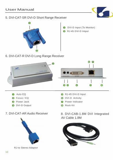
5. DVI-CAT-SR DVI-D Short Range Receiver
❶❶ DVI-D Input (To Monitor)
❷ RJ-45 DVI-D Intput
❷6. DVI-CAT-R DVI-D Long Range Receiver
❶ ❻ ❼
❷ ❸ ❹ ❺ ❽
❶ Auto EQ
❷ Focus / EQ
❸ Power Jack
❹ DVI-D Output
❺ RJ-45 DVI-D Input
❻ DVI-D Activity
❼ Power Indicator
❽ Rock Kit
7. DVI-CAT-AR Audio Receiver 8. DVI-CAB-1.8M DVI IntegratedAV Cable 1.8M
RJ-to Stereo Adaptor
10
Installation and Operation1. Install Single-Port Transmitter and Receiver:
(1) Basic Function Test: In the beginning, please connect your DVI monitorto your PC or DVI player to confirm the basic display function andremain these devices turned on for next installation sequence.
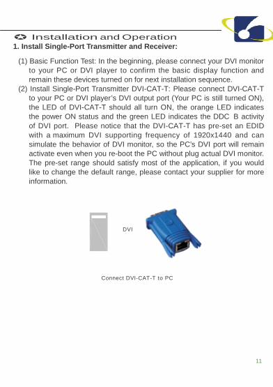
(2) Install Single-Port Transmitter DVI-CAT-T: Please connect DVI-CAT-Tto your PC or DVI player’s DVI output port (Your PC is still turned ON),the LED of DVI-CAT-T should all turn ON, the orange LED indicatesthe power ON status and the green LED indicates the DDC B activityof DVI port. Please notice that the DVI-CAT-T has pre-set an EDIDwith a maximum DVI supporting frequency of 1920x1440 and cansimulate the behavior of DVI monitor, so the PC’s DVI port will remainactivate even when you re-boot the PC without plug actual DVI monitor.The pre-set range should satisfy most of the application, if you wouldlike to change the default range, please contact your supplier for moreinformation.
DVI
Connect DVI-CAT-T to PC
11
User Manual
(3) Install Short Range Receiver DVI-CAT-SR: Pleaseconnect DVI-CAT-SR to your DVI monitor’s DVI port directly. The DVImonitor can be PDP, LCD TV, projector or LCD. The supported DVIresolution and distance will be similar to regular DVI cable. If you areusing long range receiver DVI-CAT-R, please refer to next section toinstall.
Projector PDP LCDDVI Projector Monitor
Connect directly
Short Range Receiver
(4) Install Long Range Receiver DVI-CAT-R:A. Plug power adaptor to DVI-CAT-R, the orange LED above RJ-45
should turn ON to indicate the power on status. The other LEDshould turn off, since there is no input of video signal from “SYSTEMLINK” port.
B. The “STATUS” led in the front panel will turn ON as the EQ/FOCUScontrol switch to the left end and the EQ/FOCUS will stay on AUTO,this will not function until the receiver received video signal from“SYSTEM LINK” port.
C. Connect DVI monitor’s DVI cable to the receiver.
Projector PDP LCDDVI Projector Monitor
DVI Cable
Long Range Receiver
12
(5) Selection of Cat5/5e/6 cable: You may use most ofcurrent Cat5/5e/6 cables, and since the quality varies, we doencounter some cables not perform well, even it is expensive.Therefore, please test your current cables before you installing thedevices on the site. For some environment need to prevent potentialinterference, the FTP type cable is recommended. The connectormust be made by 568B/568B type. The EIA/TIA definition of568B in the pin assignment is (1)orange white, (2)orange,(3)green white, (4)blue, (5)blue white, (6)green, (7)brown white,and (8)brown.
PAIR 3
PAIR 2 PAIR 1 PAIR 4
1 2 3 4 5 6 7 8
JACK POSITION
(6) Connect Cat5/5e/6 cable: Plug two ends of cable to Transmitter andReceiver’s RJ-45 “SYSTEM LINK” port, the Receiver’s connectedmonitor should display now and the green LED above DVI-CAT-R’sRJ-45 port should turn ON to reflect the DVI signal activation. ForDVI-CAT-R, you can manually adjust the EQ/FOCUS to have thebest DVI display. The displayed DVI resolution will also relate to thedistance been extended, it will be better to test prior actual installationand should not exceed the suggested frequency and correspondingdistance.
Projector PDP LCDDVI Projector Monitor
DVIor
Cat5e/6 cable
Connection of Single-Port DVI-D Extender
13
14
User Manual
(7) Extend Audio Signal: There is no audio function in theone-port mode,
so you need to use a pair of DVI-CAT-AR to extend the audioand the cable using is 4-wire phone cable and two ends of thecable should be made by straight RJ-11 connector.
Projector PDP LCDDVI Projector Monitor
or
Short RangeReceiver
To Speaker
Long RangeReceiver DVI-CAT-AR
DVI
DVI-CAT-T
Cat5/5e/6 cable (RJ-45 568B/568B)
AudioDVI-CAT-AR
4-Wire Photo Cable (RJ-11 Straight)
Extended Connection of DVI-D with Audio
2. Install Multi-Port Transmitter:(1) The 2/4/8-port model will all act the same except they have different
amount of outputs.(2) First Time Set-up: Please turn off the DVI output device (PC or DVD
Player) and monitors.(3) Connect local DVI monitor and speaker to the “VIDEO/AUDIO OUT” of
the transmitter and take one DVI integrated cable (DVI-CAB-1.8M),plug DVI end to “VIDEO/AUDIO IN” port of transmitter and the otherend of the cable to PC’s DVI-D video and speaker ports.
(4) Connect power adaptor.
15
(5) Turn on your DVI output device and monitor toconfirm the function of display. The “LINK” LED of the transmittershould turn orange to reflect the connection of a local DVI monitorand the “ACTIVE” LED should turn blue to indicate an activated DVI-D signal.
(6) The transmitter has built in an EDID simulator, when you connectlocal DVI monitor, the transmitter will automatically record the EDIDfrom DVI monitor. When you not connecting DVI monitor locally,the transmitter will simulate the EDID communication like a regularmonitor and activate the DVI signal of PC.
DVI+Audio Output x 1(Local Display)
DVIAudio
DVI+Audio cable
Local Connection of Multi-Port Transmitter
3. To connect monitors and speakers through RJ-45 and RJ-11 ports:(1) You can refer to previous section for Receiver to install and prepare the
cable to be connected.(2) RJ-45 VIDEO with Short Range Receiver DVI-CAT-SR: The RJ-45
ports in the back of Transmitter can only support DVI-D signal. Foreach connector, please prepare one Cat5/5e/6 cable and make thecable as 568B/568B type [more details about Cat5/5e/6 cable,please refer to previous section of 1. (3) ~ (6)], and plug one end ofthe cable to the “RJ-45 VIDEO” port and the other end to the “RJ-45”port of DVI-CAT-SR and connect “DVI-CAT-SR” to the DVI monitor. Ifthe video connectionis HDMI type, you will need to use appropriate DVI-HDMI adaptor toconnect. The supported DVI-D resolution and distance is similar tousing regular DVI cable, the estimated ranges are: 800x600@20m,1024x768@15m,1280x1024@10m. Previous range can be appliedin most of the application, but in some cases it might change. It will beappropriate to test the capacity of display before installation.
16
User Manual
(3) RJ-45 VIDEO with Long Range Receiver DVI-CAT-R:Please refer to previous section 1.(4) ~ (6) to install DVI-CAT-R and cable.If the video connection is HDMI type, you will need to use appropriateDVI-HDMI adaptor to connect. The supported DVI-D resolution anddistance is similar to regular DVI cable, the estimated ranges are:800x600@100m, 1024x768@70m, 1280x1024@60m, [email protected] range can be applied in most of the application, but in somecases it might change. It will be appropriate to test the capacity ofdisplay before installation.(4) RJ-11 AUDIO: The RJ-11 ports in the back of transmitter support stereo
audio and for each connector. Please prepare one 4-wire phone cableor use 4 wires out of the Cat5/5e/6 cable to make the RJ-11 connector.The pin definition of RJ-45 is one to one and the supported length isgreater than 50 meters (longer than the supported length of DVI-D)
Projector PDP LCDDVI Projector Monitor
orShort Range
ReceiverLong Range
Receiver
DVI+Audio Output x (Extended Display by Cat5e+Phone Cable)
Cat5/5e/6 + Phone cable
DVI+Audio Output x 1(Local Display)
DVIAudio
DVI+Audio cable
Connection of 2 -Port Transmitter
17
Stack More Transmitters to Have More Displays1. If you would like to broadcast more monitors and speakers, you
can connect another layer of same series Cat5/5e/6 DVI-D + AudioTransmitter. You can connect additional Transmitter from “VIDEO/AUDIO IN” port or “RJ-45 VIDEO and RJ-11 AUDIO” ports:
(1) From “VIDEO/AUDIO OUT”: Use one set of standard DVI/Audio cable,one end connect from the “VIDEO/AUDIO OUT” port of the first layer’s Transmitter and the other end to “DVI/AUDIO IN” port of the secondlayer’s Transmitter. (Refer to following connection ❶ )
(2) From “RJ-45 VIDEO and RJ-11 AUDIO”: Similar to the way ofconnecting monitor and speaker, you connect DVI-CAT-SR andDVS- AR to the “VIDEO/AUDIO IN” port of the second layer’sTransmitter. The length for this extension should between 10 to 25meters and the total extended length and resolution is about800x600@20m,1024x768@15m, 1280x1024@10m. Previous rangecan be applied in most of the application, but in some cases it mightchange. It will be appropriate to test the capacity of display beforeinstallation. (Refer to following connection ❷ )
Short RangeReceiver
Long RangeReceiver
Projector PDP LCDDVI Projector Monitor
x 8 x 4Cat5/5e/6 + Phone cableStandard DVI, Audio cable
10- 20 m ❶ 5 m ❷DVIAudio
DVI+Audio cable
Diagram of Connecting another Layer of Cat5/5e/6 DVI Transmitter
. To ensure the transmitting quality of DVI-D signal, more than two layer ofstacking is not recommended.
Power Consumption DC 5V, 50mA DC 5V, 800mA DC 5V, 1000mA DC 5V, 1200mA
Housing Plastic Metal
Dimension(LxWxH) mm Compact 1U Height 1U Height 1U Height
Order InformationOrder Details Part Number Remark
One-Port DVI-D Transmitter DVI-CAT-T -
One-Port DVI-D Short Range Receiver DVI-CAT-SR -
One-Port DVI-D Long Range Receiver DVI-CAT-R with DC 9V Power Adaptor x 1
One-Port Audio Receiver DVI-CAT-AR -
-Port DVI-D + Audio Transmitter DVS-102 C
With DC5V Power Adaptor x 1,DVI + Audio Integrated Cable x 1,
Rack-mount Kit x 1
4-Port DVI-D + Audio Transmitter DVI-CAT-4
With DC5V Power Adaptor x 1,DVI + Audio Integrated Cable x 1,
Rack-mount Kit x 1
8-Port DVI-D + Audio Transmitter DVI-CAT-8
With DC5V Power Adaptor x 1,DVI + Audio Integrated Cable x 1,
Rack-mount Kit x 1
19
Remarks
(1) Before operating this system, please read operationmanual carefully.(2) Please use correct power adapter and use high quality cable for
optimum broadcasting.(3) To prevent potential power damage, please don’t use 2-wire extension
cord and ensure AC outlets at relative devices on the same electronicphase and have correct grounding.
(4) Limited Warranty :A. In no events shall the direct vendor’s liability for direct or indirect,
special, incidental or consequential damages, loss of profit, loss ofbusiness, or financial loss which may be caused by the use of theproduct exceeds the price paid for the product.
B. The direct vendor makes no warranty or representation, expressedor implied with respect to the contents or use of this documentation,and especially disclaims its quality, performance, merchantability, orfitness for any particular purpose.
C. The direct vendor also reserves the right to revise or update theproduct or documentation without obligation to notify any user of suchrevisions or updates. For further information, please contact yourdirect vendor.