-- L~ -ar -.-c..e kicce..era 501: ,on .erence, 31 ..Lj YI -21 -b/ 97, Yancouver , Canada* CDN F- 97 0503 BNL-65004 .- Innovative Aspects of the SDL Control System -. REc E C ~ E D 'FE) Io 1998 W.S. Graves, S.K. Feng, P.S. Pearson, J.D. Smith National Synchrotron Light Source, Brookhaven National Lab, Upton, NY 11973 -7.1 Abstract The Source Development Lab at BNL consists of a 230 MeV electron linac and 10m long wiggler for short wave- length FEL development. The control system is based on that in use at the NSLS. Two new extensions of the con- trol system using VXI equipment are described. The first extension is the replacement of patch panels and lab oscil- loscopes to monitor RF equipment. Instead, the RF wave- forms are fed through a multiplexor into VXI digitizers. The waveforms can then be monitored remotely on any control console. The second extension is the replacement of the analog RF hardware needed to process beam posi- tion monitor signals. A digital system based on very fast (sub-nanosecond) VXI waveform digitizers is under de- velopment. The difficult operations requiring precise time alignment are then done in software. 1 INTRODUCTION The control system extensions discussed below are de- signed to increase the level of detail and the amount of information available to experimenter and accelerator op- erator alike. Most control rooms have several lab oscillo- scopes which are manually switched among different sig- nals on a patch panel as needed. This method is very lim- ited in its ability to capture and store information, and lacks the flexibility needed to change signals rapidly from any location. The new system under development greatly ex- pands the number of channels that may be used, automates their operation so that remote locations can switch signals, and integrates the data and its analysis into the main control system. It also takes advantage of the latest high-speed dig- itizers to simplify the often cumbersome analog signal pro- cessing needed before digitization. These digitizers have many features that expand their utility beyond data acquisi- tion, such as waveform integration and differentiation, FFT, standard pulse width and height measurements, a variety of digital filters, and auto-advancemode whereby many wave- forms may be acquired in rapid succession. The sections below briefly sketch the NSLS control sys- tem, and then give a detailed description of the new exten- sions including hardware, software, and current status of development. 2 NSLS CONTROL SYSTEM The control system at the Source Development Lab (SDL) is based on the system in use at the NSLS. The main NSLS facility consists of two storage rings, and an injection sys- tem comprised of a linear accelerator and Booster ring. It I has been in operation since 1979 and the control system has gone through several major upgrades [ 1,2,3]. The hardware architecture of the NSLS control system is a two-level distributed system consisting of HP Unix work- stations connected by ethernet to VME-based microproces- sor subsystems. The VME systems control and monitor the hardware status while the workstations are used as operator IO consoles. Host level applications use XI 1 and a Motif graphical interface. Standard interface libraries are used to give ap- plication programs a simplified high level interface to the hardware. At the lower level real-time software performs hardware control, data acquisition, error reporting and closed loop algorithms. It provides a standard interface to the high level programs on the host computers independent of differences at the hardware equipment level. The micro system uses a Motorola single board com- puter with an ethernet interface, battery backed memory and a utility board which provides extra timers, serial ports, bus-interrupter module, video display generator, software selectable switches and diagnostic LEDs. Each VME mi- cro has its own set of specific I/O interface and control re- quirements. The complexity and diversity of the hardware used in the facility makes each micro unique at the hardware con- trol level. To present a uniform hardware interface to the host level applications a standard set of commands for con- trol and data acquisition has been defined. Each hardware item to be monitored or controlled is treated as one or more standard devices. For instance, the fast digitizers described below are each treated as several devices; one to send dig- itization rate, another for trigger levels, and a third to set voltage ranges. 3 VXI EXTENSIONS TO VME MICROS The VME equipment has interfaces to both CAMAC and VXI crates. Most of the analog and digital I/O at the SDL is carried using legacy CAMAC equipment. The VXI equip- ment is dedicated to waveform acquisition and analysis. The first extension to the NSLS control system being tested at the SDL is the ability to measure and record many voltage waveforms using the control system. This is ac- complished using an RF multiplexor (MUX) and fast VXI waveform digitizers. The digitizers are essentially oscil- loscopes mounted in a VXI crate. Their advantages over standard lab oscilloscopes are that: 0 they are designed to be remotely controlled, Y *Work supported by the Department of Energy, c o n t r a c t s DE-ACO3-76SF00515 and DE-AC02-76CH00016Dm @ 18 Ulrlt- [OTIC QU&T ~ ---- J I' I; _.
CDN F- 97 0503 BNL-65004 .- Innovative Aspects of the SDL Control System
-. REc E C ~ E D ' FE) I o 1998 W.S. Graves, S.K. Feng, P.S. Pearson, J.D. Smith
National Synchrotron Light Source, Brookhaven National Lab, Upton, NY 11973 - 7 . 1
Abstract
The Source Development Lab at BNL consists of a 230 MeV electron linac and 10m long wiggler for short wave- length FEL development. The control system is based on that in use at the NSLS. Two new extensions of the con- trol system using VXI equipment are described. The first extension is the replacement of patch panels and lab oscil- loscopes to monitor RF equipment. Instead, the RF wave- forms are fed through a multiplexor into VXI digitizers. The waveforms can then be monitored remotely on any control console. The second extension is the replacement of the analog RF hardware needed to process beam posi- tion monitor signals. A digital system based on very fast (sub-nanosecond) VXI waveform digitizers is under de- velopment. The difficult operations requiring precise time alignment are then done in software.
1 INTRODUCTION
The control system extensions discussed below are de- signed to increase the level of detail and the amount of information available to experimenter and accelerator op- erator alike. Most control rooms have several lab oscillo- scopes which are manually switched among different sig- nals on a patch panel as needed. This method is very lim- ited in its ability to capture and store information, and lacks the flexibility needed to change signals rapidly from any location. The new system under development greatly ex- pands the number of channels that may be used, automates their operation so that remote locations can switch signals, and integrates the data and its analysis into the main control system. It also takes advantage of the latest high-speed dig- itizers to simplify the often cumbersome analog signal pro- cessing needed before digitization. These digitizers have many features that expand their utility beyond data acquisi- tion, such as waveform integration and differentiation, FFT, standard pulse width and height measurements, a variety of digital filters, and auto-advance mode whereby many wave- forms may be acquired in rapid succession.
The sections below briefly sketch the NSLS control sys- tem, and then give a detailed description of the new exten- sions including hardware, software, and current status of development.
2 NSLS CONTROL SYSTEM
The control system at the Source Development Lab (SDL) is based on the system in use at the NSLS. The main NSLS facility consists of two storage rings, and an injection sys- tem comprised of a linear accelerator and Booster ring. It
I
has been in operation since 1979 and the control system has gone through several major upgrades [ 1,2,3].
The hardware architecture of the NSLS control system is a two-level distributed system consisting of HP Unix work- stations connected by ethernet to VME-based microproces- sor subsystems. The VME systems control and monitor the hardware status while the workstations are used as operator IO consoles.
Host level applications use XI 1 and a Motif graphical interface. Standard interface libraries are used to give ap- plication programs a simplified high level interface to the hardware.
At the lower level real-time software performs hardware control, data acquisition, error reporting and closed loop algorithms. It provides a standard interface to the high level programs on the host computers independent of differences at the hardware equipment level.
The micro system uses a Motorola single board com- puter with an ethernet interface, battery backed memory and a utility board which provides extra timers, serial ports, bus-interrupter module, video display generator, software selectable switches and diagnostic LEDs. Each VME mi- cro has its own set of specific I/O interface and control re- quirements.
The complexity and diversity of the hardware used in the facility makes each micro unique at the hardware con- trol level. To present a uniform hardware interface to the host level applications a standard set of commands for con- trol and data acquisition has been defined. Each hardware item to be monitored or controlled is treated as one or more standard devices. For instance, the fast digitizers described below are each treated as several devices; one to send dig- itization rate, another for trigger levels, and a third to set voltage ranges.
3 VXI EXTENSIONS TO VME MICROS
The VME equipment has interfaces to both CAMAC and VXI crates. Most of the analog and digital I/O at the SDL is carried using legacy CAMAC equipment. The VXI equip- ment is dedicated to waveform acquisition and analysis.
The first extension to the NSLS control system being tested at the SDL is the ability to measure and record many voltage waveforms using the control system. This is ac- complished using an RF multiplexor (MUX) and fast VXI waveform digitizers. The digitizers are essentially oscil- loscopes mounted in a VXI crate. Their advantages over standard lab oscilloscopes are that:
0 they are designed to be remotely controlled,
Y *Work s u p p o r t e d by the D e p a r t m e n t of Energy, c o n t r a c t s DE-ACO3-76SF00515 and D E - A C 0 2 - 7 6 C H 0 0 0 1 6 D m @ 18 Ulrlt-
[OTIC QU&T ~ ---- J I' I; _.
A
0 they have the memory and bus bandwidth needed for high speed data transmission,
0 they can maintain precise timing information syn- chronous with accelerator timing signals,
0 they may be integrated with other sophisticated VXI equipment such as timing and signal generators.
Figure 1 shows the layout of the VME and VXI crates used to control the digitizers. In the VXI crate there are two Tektronix 4-channel 1 GS/s TVS641 digitizers used for general purpose data acquisition, and one two channel 5 GS/s TVS625 digitizer used for beam position monitor (BPM) processing [4]. In addition there is a card for com- munication with the controlling VME crate, and a 1.5 GHz RF MUX with 32 input channels and 8 output channels. The 8 outputs are sent to the two 4-channel digitizers. Thus this system can simultaneously monitor 8 of 32 waveforms in addition to the BPM processing.
Ethernet v L _ _ r l Q I I I 'I - 5:
X b U
T
VME
VXI - E 5: C X
I to RF Equipment
Figure 1 : VME and VXI hardware at SDL.
4 LOW-LEVEL CONTROLS
The communication between the VME CPU and the VXI devices is done via VME-MXI-VXI hardware and soft- ware. The VME-MXI-VXI hardware requires simple ini- tializations to configure/enable the address maps. After- wards, the MXI system becomes a transparent VME chas- sis extender.
A resource manager configures the VXI devices, per- forms a system self-test and diagnostic sequence, config- ures the system's address map, commander/servant hierar- chies, allocates IRQ lines, and initiates normal operation.
Both the waveform digitizer and RF MUX provide a VXI word-serial protocol for commands and data transfers. The software provides routines to read and write VXI message- based devices, to detect protocol errors, and a watchdog
timer to limit the transfer time between CPU and VXI de- vices.
Early in the evaluation stage tests of data transfer rates were done on different combinations of hardware platforms using a MVME162 CPU running VxWorks. Using GPIB controllers in the VME and VXI crates, the DMA data transfer rate was 12 kbytes/s from the TVS625. Using high performance MXI connections we measured a 2 1 kbytes/s transfer rate using the word-serial protocol. We then de- veloped a Fast Data Channel (FDC) driver to replace the word-serial protocol. This FDC driver (without DMA) per- formed roughly a factor of ten faster than the word-serial protocol. Utilizing the digitizers' auto-advance mode to transfer multiple waveforms without software intervention, the FDC driver without DMA performed at 883 kbytes/s for 100 records of data.
5 HIGH LEVEL CONTROLS
Figure 2 shows the main user interface to the SDL Scope Control and Monitor program. The program is being devel- oped using the XRT/Graph package under X11 and Motif. Devices are selected by clicking the appropriate pushbutton on the screen.
Figure 2: User interface to waveform digitizers.
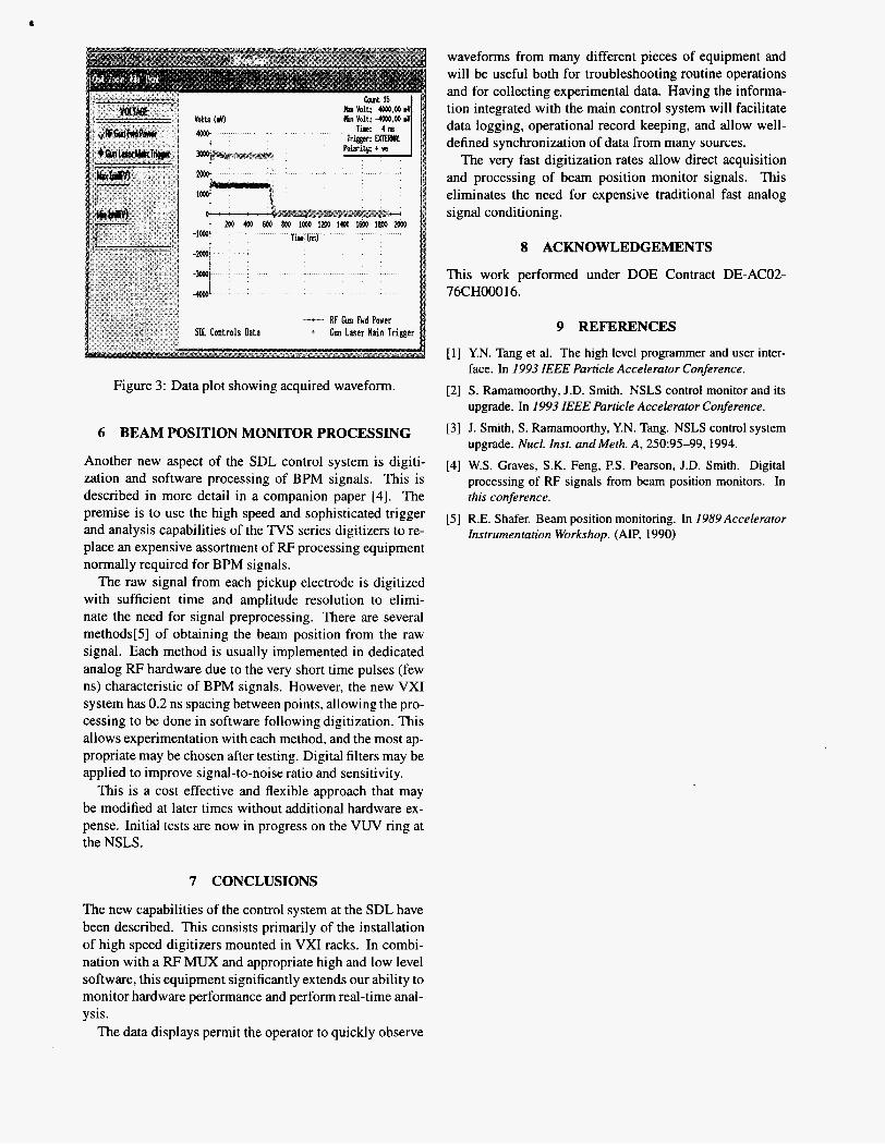
To view the trace from any device the Start pushbutton is selected. Figure 3 shows an example of the screen that then appears. The program graphs an array of data read from the scope micro device. It also provides the ability to alter the voltage range, trigger source and mode, and digitizer sample rate for each device that is being displayed.
The graph data is automatically updated in real time, is resizable, and zoom and print functions allow the user to study the data more closely. Any graph may be saved to file, for later recall and display.
DISCLAIMER
This report was prepared as an account of work sponsored by an agency of the United States Government. Neither the United States Government oor any agency thereof, nor any of their employees, makes any warranty, express or implied, or assumes any legal liability or responsibility for the accuracy, completeness, or use- fulness of any information, apparatus, product, or process disclosed, or represents that its use would not infringe privately owned rights. Reference herein to any spc- cific commercial product, process, or service by trade name, trademark, manufac- turer, or otherwise does not necessarily constitute or imply its endorsement. recom- mendation, or favoring by the United States Government or any agency thereof. The views and opinions of authors expressed herein do not necessarily state or reflect those of the United States Government or any agency thereof.
waveforms from many different pieces of equipment and will be useful both for troubleshooting routine operations and for collecting experimental data. Having the informa- tion integrated with the main control system will facilitate data logging, operational record keeping, and allow well- defined synchronization of data from many sources.
The very fast digitization rates allow direct acquisition and processing of beam position monitor signals. This eliminates the need for expensive traditional fast analog signal conditioning.
8 ACKNOWLEDGEMENTS
This work performed under DOE Contract DE-ACO2- 76CH00016.
9 REFERENCES
[ 11 Y.N. Tang et al. The high level programmer and user inter- face. In 1993 IEEE Particle Accelerator Conference.
[2] S . Ramamoorthy, J.D. Smith. NSLS control monitor and its upgrade. In 1993 IEEE Particle Accelerator Conference.
Figure 3: Data plot showing acquired waveform.
6 BEAM POSITION MONITOR PROCESSING [3] J. Smith, S. Ramamoorthy, Y.N. Tang. NSLS control system upgrade. Nucl. Inst. andMeth. A, 250~95-99,1994.
Another new aspect of the SDL control system is digiti- zation and software processing of BPM signals. This is described in more detail in a companion paper [4]. The premise 1s to use the high speed and SoPhiSticated trigger and analysis capabilities of the TVS series digitizers to re- place an expensive assortment of RF processing equipment normally required for BPM signals.
The raw signal from each pickup electrode is digitized with sufficient time and amplitude resolution to elimi- nate the need for signal preprocessing. There are several methods[5] of obtaining the beam position from the raw signal. Each method is usually implemented in dedicated analog RF hardware due to the very short time pulses (few ns) characteristic of BPM signals. However, the new VXI system has 0.2 ns spacing between points, allowing the pro- cessing to be done in software following digitization. This allows experimentation with each method, and the most ap- propriate may be chosen after testing. Digital filters may be applied to improve signal-to-noise ratio and sensitivity.
This is a cost effective and flexible approach that may be modified at later times without additional hardware ex- pense. Initial tests are now in progress on the VUV ring at the NSLS.
[4] W.S. Graves, S.K. Feng, PS. Pearson, J.D. Smith. Digital processing of RF signals from beam position monitors. In this conference.
[5] R.E. Shafer. Beam position monitoring. In 1989 Accelerator Instrumentation Workshop. (AIP, 1990)
7 CONCLUSIONS
The new capabilities of the control system at the SDL have been described. This consists primarily of the installation of high speed digitizers mounted in VXI racks. In combi- nation with a RF MUX and appropriate high and low level software, this equipment significantly extends our ability to monitor hardware performance and perform real-time anal- ysis.
The data displays permit the operator to quickly observe