1 - Do not store or use gasoline or other flam- mable vapors and liquids in the vicinity of this or any other appliance. - What to do if you smell gas • Do not try to light any appliance. • Do not touch any electrical switch. • Do not use any phone in your building. • Immediately call your gas supplier from a neighbor's phone. Follow the gas supplier's instructions. • If you cannot reach your gas supplier, call the fire department. - Installation and service must be performed by a qualified installer, service agency, or the gas supplier. Models: Pier-TRC ST-TRC L-Corner-TRC R-Corner-TRC Installers Guide WARNING: IMPROPER INSTALLA- TION, ADJUSTMENT, ALTERATION, SERVICE OR MAINTENANCE CAN CAUSE INJURY OR PROPERTY DAM- AGE. REFER TO THIS MANUAL. FOR ASSISTANCE OR ADDITIONAL INFOR- MATION CONSULT A QUALIFIED IN- STALLER, SERVICE AGENCY, OR THE GAS SUPPLIER. Underwriters Laboratories Listed 501-900M 11/02 READ THIS MANUAL BEFORE INSTALLING OR OPERATING THIS APPLIANCE. THIS INSTALLERS GUIDE MUST BE LEFT WITH APPLIANCE FOR FUTURE REFERENCE. 1. This appliance may be installed in an af- termarket, permanently located, manufac- tured (mobile) home, where not prohibited by local codes. 2. This appliance is only for use with the type of gas indicated on the rating plate. This appliance is not convertible for use with other gases, unless a certified kit is used. Please contact your Heat-N-Glo dealer with any questions or concerns. For the number of your nearest Heat-N-Glo dealer, please call 1-888-427-3973. Printed in U.S.A. Copyright 2002, Heat-N-Glo, a division of Hearth Technologies Inc. 20802 Kensington Boulevard, Lakeville, MN 55044 WARNING: IF THE INFORMATION IN THESE INSTRUCTIONS IS NOT FOLLOWED EXACTLY, A FIRE OR EXPLOSION MAY RESULT CAUS- ING PROPERTY DAMAGE, PER- SONAL INJURY, OR DEATH. This product is covered by one or more of the following patents: (United States) 4,112,913; 4,408,594; 4,422,426; 4,424,792; 4,520,791; 4,793,322; 4,852,548; 4,875,464; 5,000,162; 5,016,609; 5,076,254 5,191,877; 5,218,953; 5,328,356; 5,429,495; 5,452,708; 5,542,407; 5,613,487; (Australia) 543790; 586383; (Canada) 1,123,296; 1,297,746; 2,195,264; (Mexico) 97-0457; (New Zealand) 200265; or other U.S. and foreign patents pending.
Transcript
1
- Do not store or use gasoline or other flam-mable vapors and liquids in the vicinity of thisor any other appliance.
- What to do if you smell gas
• Do not try to light any appliance.
• Do not touch any electrical switch.
• Do not use any phone in your building.
• Immediately call your gas supplier from aneighbor's phone. Follow the gas supplier'sinstructions.
• If you cannot reach your gas supplier, callthe fire department.
- Installation and service must be performed by aqualified installer, service agency, or the gassupplier.
Models:Pier-TRCST-TRCL-Corner-TRCR-Corner-TRC
Installers Guide
WARNING: IMPROPER INSTALLA-TION, ADJUSTMENT, ALTERATION,SERVICE OR MAINTENANCE CANCAUSE INJURY OR PROPERTY DAM-AGE. REFER TO THIS MANUAL. FORASSISTANCE OR ADDITIONAL INFOR-MATION CONSULT A QUALIFIED IN-STALLER, SERVICE AGENCY, OR THEGAS SUPPLIER.
UnderwritersLaboratories Listed
501-900M 11/02
READ THIS MANUAL BEFORE INSTALLING OROPERATING THIS APPLIANCE. THIS INSTALLERSGUIDE MUST BE LEFT WITH APPLIANCE FORFUTURE REFERENCE.
1. This appliance may be installed in an af-termarket, permanently located, manufac-tured (mobile) home, where not prohibitedby local codes.
2. This appliance is only for use with the typeof gas indicated on the rating plate. Thisappliance is not convertible for use withother gases, unless a certified kit is used.
Please contact your Heat-N-Glo dealer with anyquestions or concerns. For the number of your nearestHeat-N-Glo dealer, please call 1-888-427-3973.
Printed in U.S.A. Copyright 2002,Heat-N-Glo, a division of Hearth Technologies Inc.20802 Kensington Boulevard, Lakeville, MN 55044
WARNING: IF THE INFORMATIONIN THESE INSTRUCTIONS IS NOTFOLLOWED EXACTLY, A FIRE OREXPLOSION MAY RESULT CAUS-ING PROPERTY DAMAGE, PER-SONAL INJURY, OR DEATH.
This product is covered by one or more of the following patents: (United States) 4,112,913; 4,408,594; 4,422,426; 4,424,792; 4,520,791; 4,793,322;4,852,548; 4,875,464; 5,000,162; 5,016,609; 5,076,254 5,191,877; 5,218,953; 5,328,356; 5,429,495; 5,452,708; 5,542,407; 5,613,487; (Australia)543790; 586383; (Canada) 1,123,296; 1,297,746; 2,195,264; (Mexico) 97-0457; (New Zealand) 200265; or other U.S. and foreign patents pending.
2
These units MUST use one of the vent systemsdescribed in the Installing the Fireplace section ofthe Installers Guide. NO OTHER vent systems orcomponents MAY BE USED.
This gas fireplace and vent assembly MUST bevented directly to the outside and MUST NEVER beattached to a chimney serving a separate solid fuelburning appliance. Each gas appliance MUST USEa separate vent system. Common vent systems arePROHIBITED.
INSPECT the external vent cap on a regular basis tomake sure that no debris is interfering with the airflow.
The glass door assembly MUST be in place andsealed, and the trim door assembly MUST be inplace on the fireplace before the unit can be placedinto safe operation.
DO NOT OPERATE this appliance with the glassdoor removed, cracked, or broken. Replacement ofthe glass door should be performed by a licensedor qualified service person. DO NOT strike or slamthe glass door.
The glass door assembly SHALL ONLY bereplaced as a complete unit, as supplied by the gasfireplace manufacturer. NO SUBSTITUTE materialmay be used.
DO NOT USE abrasive cleaners on the glass doorassembly. DO NOT ATTEMPT to clean the glassdoor when it is hot.
Turn off the gas before servicing this appliance. It isrecommended that a qualified service technicianperform an appliance check-up at the beginning ofeach heating season.
Any safety screen or guard removed for servicingmust be replaced before operating this appliance.
DO NOT place furniture or any other combustiblehousehold objects within 36 inches of the fireplacefront.
READ and UNDERSTAND all instructions carefullybefore starting the installation. FAILURE TOFOLLOW these installation instructions may resultin a possible fire hazard and will void the warranty.
Prior to the first firing of the fireplace, READ theUsing Your Fireplace section of the Owners Guide.
DO NOT USE this appliance if any part has beenunder water. Immediately CALL a qualified servicetechnician to inspect the unit and to replace any partof the control system and any gas control which hasbeen under water.
THIS UNIT IS NOT FOR USE WITH SOLID FUEL.
Installation and repair should be PERFORMED by aqualified service person. The appliance and ventingsystem should be INSPECTED before initial useand at least annually by a professional serviceperson. More frequent cleaning may be requireddue to excessive lint from carpeting, beddingmaterial, etc. It is IMPERATIVE that the unit’scontrol compartment, burners, and circulating airpassageways BE KEPT CLEAN to provide foradequate combustion and ventilation air.
Always KEEP the appliance clear and free fromcombustible materials, gasoline, and otherflammable vapors and liquids.
NEVER OBSTRUCT the flow of combustion andventilation air. Keep the front of the applianceCLEAR of all obstacles and materials for servicingand proper operations.
Due to the high temperature, the appliance shouldbe LOCATED out of traffic areas and away fromfurniture and draperies. Clothing or flammablematerial SHOULD NOT BE PLACED on or near theappliance.
Children and adults should be ALERTED to thehazards of high surface temperature and shouldSTAY AWAY to avoid burns or clothing ignition.Young children should be CAREFULLY SUPERVISEDwhen they are in the same room as the appliance.
!
!
!
!
!
!!
! !
!
!
!
!
!
!
!
!
SAFETY AND WARNING INFORMATION
!
!
3
TABLE OF CONTENTS
Safety and Warning Information ............................................... 2
Service Parts Lists .................................................................... 4
Section 1: Approvals and Codes ............................................ 12
Approval Listings and Codes ..................................................... 12
Placing the Ember Material ......................................... 38
Step 11 Before Lighting the Fireplace ...................................... 39
Step 12 Lighting the Fireplace .................................................. 39
After the Installation .................................................................... 39
Section 4: Maintaining and Servicing Your Fireplace ......... 40
u = Contains updated information.
u
u
u
u
u
4
* Part number list on following page.
* La liste des numéros de pièce se trouve à la page suivante.
2
3
Standing Pilot
3
5
6
4
7
1
8 Log Assembly
u(NG, LP) Exploded Parts Diagram(GN, PL) Vue éclatée des pièces
Service Parts Pier-TRCBeginning Manufacturing Date: 6-97Ending Manufacturing Date: ______
5
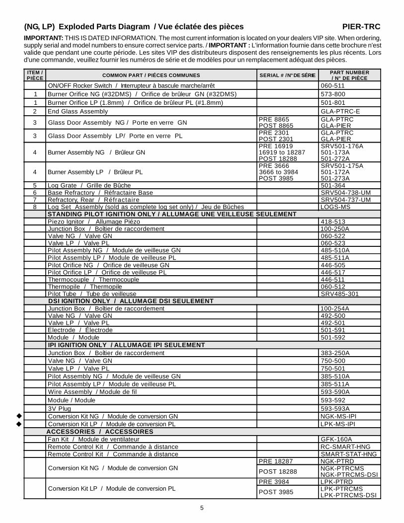
(NG, LP) Exploded Parts Diagram / Vue éclatée des piècesIMPORTANT: THIS IS DATED INFORMATION. The most current information is located on your dealers VIP site. When ordering,supply serial and model numbers to ensure correct service parts. / IMPORTANT : L'information fournie dans cette brochure n'estvalide que pendant une courte période. Les sites VIP des distributeurs disposent des renseignements les plus récents. Lorsd'une commande, veuillez fournir les numéros de série et de modèles pour un remplacement adéquat des pièces.
ITEM /PIÈCE COMMON PART / PIÉCES COMMUNES SERIAL # / N° DE SÉRIE PART NUMBER
/ N° DE PIÈCE
ON/OFF Rocker Switch / Interrupteur à bascule marche/arrêt 060-5111 Burner Orifice NG (#32DMS) / Orifice de brûleur GN (#32DMS) 573-8001 Burner Orifice LP (1.8mm) / Orifice de brûleur PL (#1.8mm) 501-8012 End Glass Assembly GLA-PTRC-E
3 Glass Door Assembly NG / Porte en verre GN PRE 8865POST 8865
GLA-PTRCGLA-PIER
3 Glass Door Assembly LP/ Porte en verre PL PRE 2301POST 2301
GLA-PTRCGLA-PIER
4 Burner Assembly NG / Brûleur GNPRE 1691916919 to 18287POST 18288
5 Log Grate / Grille de Bûche 501-3646 Base Refractory / Réfractaire Base SRV504-738-UM7 Refractory, Rear / Réfractaire SRV504-737-UM8 Log Set Assembly (sold as complete log set only) / Jeu de Bûches LOGS-MS
STANDING PILOT IGNITION ONLY / ALLUMAGE UNE VEILLEUSE SEULEMENTPiezo Ignitor / Allumage Piézo 418-513Junction Box / Boîtier de raccordement 100-250AValve NG / Valve GN 060-522Valve LP / Valve PL 060-523Pilot Assembly NG / Module de veilleuse GN 485-510APilot Assembly LP / Module de veilleuse PL 485-511APilot Orifice NG / Orifice de veilleuse GN 446-505Pilot Orifice LP / Orifice de veilleuse PL 446-517Thermocouple / Thermocouple 446-511Thermopile / Thermopile 060-512Pilot Tube / Tube de veilleuse SRV485-301
DSI IGNITION ONLY / ALLUMAGE DSI SEULEMENTJunction Box / Boîtier de raccordement 100-254AValve NG / Valve GN 492-500Valve LP / Valve PL 492-501Electrode / Électrode 501-591Module / Module 501-592IPI IGNITION ONLY / ALLUMAGE IPI SEULEMENTJunction Box / Boîtier de raccordement 383-250AValve NG / Valve GN 750-500Valve LP / Valve PL 750-501Pilot Assembly NG / Module de veilleuse GN 385-510APilot Assembly LP / Module de veilleuse PL 385-511AWire Assembly / Module de fil 593-590AModule / Module 593-5923V Plug 593-593AConversion Kit NG / Module de conversion GN NGK-MS-IPIConversion Kit LP / Module de conversion PL LPK-MS-IPI
ACCESSORIES / ACCESSOIRESFan Kit / Module de ventilateur GFK-160ARemote Control Kit / Commande à distance RC-SMART-HNGRemote Control Kit / Commande à distance SMART-STAT-HNG
Conversion Kit NG / Module de conversion GNPRE 18287 NGK-PTRD
POST 18288 NGK-PTRCMSNGK-PTRCMS-DSI
Conversion Kit LP / Module de conversion PLPRE 3984 LPK-PTRD
POST 3985 LPK-PTRCMSLPK-PTRCMS-DSI
u
PIER-TRC
u
6
* Part number list on following page.
* La liste des numéros de pièce se trouve à la page suivante.
7 Log Assembly
1
STANDING PILOT
2
4
5
6
3
2
u(NG, LP) Exploded Parts Diagram(GN, PL) Vue éclatée des pièces
Service Parts ST-TRCBeginning Manufacturing Date: 6-97Ending Manufacturing Date: ______
7
(NG, LP) Exploded Parts Diagram / Vue éclatée des piècesIMPORTANT: THIS IS DATED INFORMATION. The most current information is located on your dealers VIP site. When ordering,supply serial and model numbers to ensure correct service parts. / IMPORTANT : L'information fournie dans cette brochure n'estvalide que pendant une courte période. Les sites VIP des distributeurs disposent des renseignements les plus récents. Lorsd'une commande, veuillez fournir les numéros de série et de modèles pour un remplacement adéquat des pièces.
ITEM /PIÈCE COMMON PARTS / I PIÉCES COMMUNES SERIAL #
/ N° DE SÉRIEPART NUMBER/ N° DE PIÈCE
ON/OFF Rocker Switch / Interrupteur à bascule marche/arrêt 060-5111 Burner Orifice NG (#32DMS) / Orifice de brûleur GN (#32DMS) 573-8001 Burner Orifice LP (1.8mm) / Orifice de brûleur PL (1.8mm) 501-801
2 Glass Door Assembly NG / Porte en verre GN PRE 8558POST 8558
GLA-PTRCGLA-PIER
2 Glass Door Assembly LP / Porte en verre PL PRE 2254POST 2254
GLA-PTRCGLA-PIER
3 Burner Assembly NG / Brûleur GNPRE 1606716067 to 18029POST 18030
4 Log Grate / Grille de Bûche 501-3645 Base Refractory / Réfractaire Base SRV504-738-UM6 Refractory, Rear / Réfractaire SRV504-737-UM7 Log Set Assembly (sold as complete log set only) / Jeu de Bûches LOGS-MS
STANDING PILOT IGNITION ONLY / ALLUMAGE UNE VEILLEUSE SEULEMENTPiezo Ignitor / Allumage Piézo 418-513Junction Box / Boîtier de raccordement 100-250AValve NG / Valve GN 060-522Valve LP / Valve PL 060-523Pilot Assembly NG / Module de veilleuse GN 485-510APilot Assembly LP / Module de veilleuse PL 485-511APilot Orifice NG / Orifice de veilleuse GN 446-505Pilot Orifice LP / Orifice de veilleuse PL 446-517Thermocouple / Thermocouple 446-511Thermopile / Thermopile 060-512Pilot Tube / Tube de veilleuse SRV485-301
DSI IGNITION ONLY / ALLUMAGE DSI SEULEMENTJunction Box / Boîtier de raccordement 100-254AValve NG / Valve GN 492-500Valve LP / Valve PL 492-501Electrode / Électrode 501-591Module / Module 501-592IPI IGNITION ONLY / ALLUMAGE IPI SEULEMENTJunction Box / Boîtier de raccordement 383-250AValve NG / Valve GN 750-500Valve LP / Valve PL 750-501Pilot Assembly NG / Module de veilleuse GN 385-510APilot Assembly LP / Module de veilleuse PL 385-511AWire Assembly / Module de fil 593-590AModule / Module 593-5923V Plug 593-593AConversion Kit NG / Module de conversion GN NGK-MS-IPIConversion Kit LP / Module de conversion PL LPK-MS-IPI
ACCESSORIES / ACCESSOIRESFan Kit / Module de ventilateur GFK-160ARemote Control Kit / Commande à distance RC-SMART-HNGRemote Control Kit / Commande à distance SMART-STAT-HNG
Conversion Kit NG / Module de conversion GNPRE 18029 NGK-PTRD
POST 18030 NGK-PTRCMSNGK-PTRCMS-DSI
Conversion Kit LP / Module de conversion PLPRE 3994 LPK-PTRD
POST 3995 LPK-PTRCMSLPK-PTRCMS-DSI
uu
ST-TRC
8
* Part number list on following page.
* La liste des numéros de pièce se trouve à la page suivante.
9 Log Assembly
STANDING PILOT
1
2
5
6
4
3
7
8
15
u(NG, LP) Exploded Parts Diagram(GN, PL) Vue éclatée des pièces
Service Parts L-Corner-TRCBeginning Manufacturing Date: 6-97Ending Manufacturing Date: ______
9
(NG, LP) Exploded Parts Diagram / Vue éclatée des pièces
IMPORTANT: THIS IS DATED INFORMATION. The most current information is located on your dealers VIP site. When ordering,supply serial and model numbers to ensure correct service parts. / IMPORTANT : L'information fournie dans cette brochure n'estvalide que pendant une courte période. Les sites VIP des distributeurs disposent des renseignements les plus récents. Lorsd'une commande, veuillez fournir les numéros de série et de modèles pour un remplacement adéquat des pièces.
ITEM /PIÈCE COMMON PARTS / PIÉCES COMMUNES SERIAL #
/ N° DE SÉRIEPART NUMBER/ N° DE PIÈCE
ON/OFF Rocker Switch / Interrupteur à bascule marche/arrêt 060-5111 Burner Orifice NG (#32DMS) / Orifice de brûleur GN (#32DMS) 573-8001 Burner Orifice LP (1.8mm) / Orifice de brûleur PL (1.8mm) 501-8012 Glass Door Assembly, End / Porte en verre GLA-PTRC-E
3 Glass Door Assembly NG / Porte en verre GN PRE 1957POST 1957
GLA-PTRCGLA-PIER
3 Glass Door Assembly LP/ Porte en verre PL PRE 1232POST 1232
GLA-PTRCGLA-PIER
4 Burner Assembly NG / Brûleur GNPRE 29202920 to 3102POST 3103
5 Log Grate / Grille de Bûche 501-3646 Base Refractory / Réfractaire Base SRV504-738-UM7 Refractory, Rear / Réfractaire SRV504-737-UM8 Refractory, Back / Réfractaire SRV504-736-UM9 Log Set Assembly (sold as complete log set only) / Jeu de Bûches LOGS-MS
STANDING PILOT IGNITION ONLY / ALLUMAGE UNE VEILLEUSE SEULEMENTPiezo Ignitor / Allumage Piézo 418-513Junction Box / Boîtier de raccordement 100-250AValve NG / Valve GN 060-522Valve LP / Valve PL 060-523Pilot Assembly NG / Module de veilleuse GN 485-510APilot Assembly LP / Module de veilleuse PL 485-511APilot Orifice NG / Orifice de veilleuse GN 446-505Pilot Orifice LP / Orifice de veilleuse PL 446-517Thermocouple / Thermocouple 446-511Thermopile / Thermopile 060-512Pilot Tube / Tube de veilleuse SRV485-301
DSI IGNITION ONLY / ALLUMAGE DSI SEULEMENTJunction Box / Boîtier de raccordement 100-254AValve NG / Valve GN 492-500Valve LP / Valve PL 492-501Electrode / Électrode 501-591Module / Module 501-592IPI IGNITION ONLY / ALLUMAGE IPI SEULEMENTJunction Box / Boîtier de raccordement 383-250AValve NG / Valve GN 750-500Valve LP / Valve PL 750-501Pilot Assembly NG / Module de veilleuse GN 385-510APilot Assembly LP / Module de veilleuse PL 385-511AWire Assembly / Module de fil 593-590AModule / Module 593-5923V Plug 593-593AConversion Kit NG / Module de conversion GN NGK-MS-IPIConversion Kit LP / Module de conversion PL LPK-MS-IPI
ACCESSORIES / ACCESSOIRESFan Kit / Module de ventilateur GFK-160ARemote Control Kit / Commande à distance RC-SMART-HNGRemote Control Kit / Commande à distance SMART-STAT-HNG
Conversion Kit NG / Module de conversion GN PRE 3102POST 3103
NGK-PTRDNGK-PTRCMS
Conversion Kit LP / Module de conversion PL PRE 1472POST 1473
LPK-PTRDLPK-PTRCMS
uu
L-CORNER-TRC
10
* Part number list on following page.
* La liste des numéros de pièce se trouve à la page suivante.
STANDING PILOT
1
3
7
8
4
6
5
2
9 Log Assembly
u(NG, LP) Exploded Parts Diagram(GN, PL) Vue éclatée des pièces
Service Parts R-Corner-TRCBeginning Manufacturing Date: 6-97Ending Manufacturing Date: ______
11
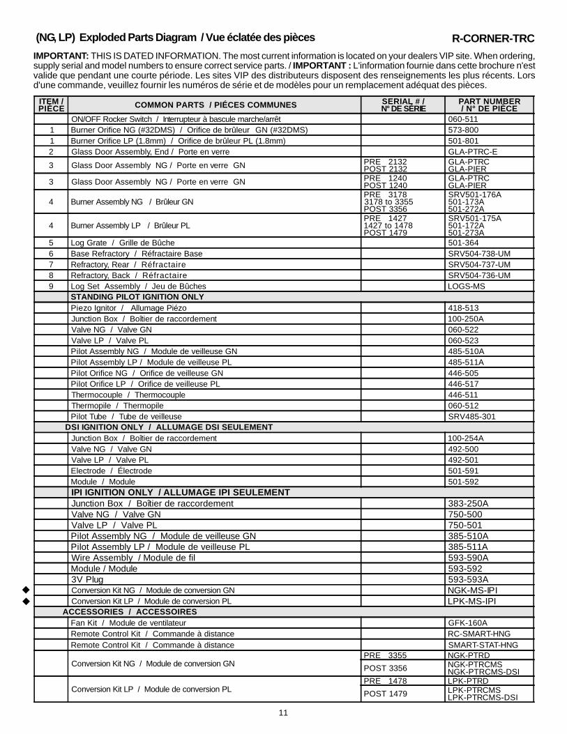
(NG, LP) Exploded Parts Diagram / Vue éclatée des pièces
IMPORTANT: THIS IS DATED INFORMATION. The most current information is located on your dealers VIP site. When ordering,supply serial and model numbers to ensure correct service parts. / IMPORTANT : L'information fournie dans cette brochure n'estvalide que pendant une courte période. Les sites VIP des distributeurs disposent des renseignements les plus récents. Lorsd'une commande, veuillez fournir les numéros de série et de modèles pour un remplacement adéquat des pièces.
ITEM /PIÈCE COMMON PARTS / PIÉCES COMMUNES SERIAL # /
N° DE SÉRIEPART NUMBER/ N° DE PIÈCE
ON/OFF Rocker Switch / Interrupteur à bascule marche/arrêt 060-5111 Burner Orifice NG (#32DMS) / Orifice de brûleur GN (#32DMS) 573-8001 Burner Orifice LP (1.8mm) / Orifice de brûleur PL (1.8mm) 501-8012 Glass Door Assembly, End / Porte en verre GLA-PTRC-E
3 Glass Door Assembly NG / Porte en verre GN PRE 2132POST 2132
GLA-PTRCGLA-PIER
3 Glass Door Assembly NG / Porte en verre GN PRE 1240POST 1240
GLA-PTRCGLA-PIER
4 Burner Assembly NG / Brûleur GNPRE 31783178 to 3355POST 3356
5 Log Grate / Grille de Bûche 501-3646 Base Refractory / Réfractaire Base SRV504-738-UM7 Refractory, Rear / Réfractaire SRV504-737-UM8 Refractory, Back / Réfractaire SRV504-736-UM9 Log Set Assembly / Jeu de Bûches LOGS-MS
STANDING PILOT IGNITION ONLYPiezo Ignitor / Allumage Piézo 418-513Junction Box / Boîtier de raccordement 100-250AValve NG / Valve GN 060-522Valve LP / Valve PL 060-523Pilot Assembly NG / Module de veilleuse GN 485-510APilot Assembly LP / Module de veilleuse PL 485-511APilot Orifice NG / Orifice de veilleuse GN 446-505Pilot Orifice LP / Orifice de veilleuse PL 446-517Thermocouple / Thermocouple 446-511Thermopile / Thermopile 060-512Pilot Tube / Tube de veilleuse SRV485-301
DSI IGNITION ONLY / ALLUMAGE DSI SEULEMENTJunction Box / Boîtier de raccordement 100-254AValve NG / Valve GN 492-500Valve LP / Valve PL 492-501Electrode / Électrode 501-591Module / Module 501-592IPI IGNITION ONLY / ALLUMAGE IPI SEULEMENTJunction Box / Boîtier de raccordement 383-250AValve NG / Valve GN 750-500Valve LP / Valve PL 750-501Pilot Assembly NG / Module de veilleuse GN 385-510APilot Assembly LP / Module de veilleuse PL 385-511AWire Assembly / Module de fil 593-590AModule / Module 593-5923V Plug 593-593AConversion Kit NG / Module de conversion GN NGK-MS-IPIConversion Kit LP / Module de conversion PL LPK-MS-IPI
ACCESSORIES / ACCESSOIRESFan Kit / Module de ventilateur GFK-160ARemote Control Kit / Commande à distance RC-SMART-HNGRemote Control Kit / Commande à distance SMART-STAT-HNG
Conversion Kit NG / Module de conversion GNPRE 3355 NGK-PTRD
POST 3356 NGK-PTRCMSNGK-PTRCMS-DSI
Conversion Kit LP / Module de conversion PLPRE 1478 LPK-PTRD
POST 1479 LPK-PTRCMSLPK-PTRCMS-DSI
uu
R-CORNER-TRC
12
Appliance Certification
The Heat-N-Glo fireplace models discussed in this InstallersGuide have been tested to certification standards and listedby the applicable laboratories.
LABORATORY: Underwriters LaboratoriesTYPE: Direct Vent Gas FireplaceSTANDARD: ANSI Z21.50•CGA2.22•UL307B
Installation CodesThe fireplace installation must conform to local codes. Beforeinstalling the fireplace, consult the local building codeagency to ensure that you are in compliance with allapplicable codes, including permits and inspections.
In the absence of local codes, the fireplace installation mustconform to the National Fuel Gas Code ANSI Z223.1 (inthe United States) or the CAN/CGA-B149 Installation Codes(in Canada). The appliance must be electrically groundedin accordance with local codes or, in the absence of localcodes with the National Electric Code ANSI/NFPA No. 70(in the United States), or to the CSA C22.1 Canadian ElectricCode (in Canada).
These models may be installed in a bedroom or bed-sittingroom in the U.S.A. and Canada.
Approvals andCodes
High Altitude InstallationsU.L. Listed gas appliances are tested and approved with-out requiring changes for elevations from 0 to 2,000 feet inthe U. S. A. and in Canada.
When installing this appliance at an elevation above 2,000feet, it may be necessary to decrease the input rating bychanging the existing burner orifice to a smaller size. Inputrate should be reduced by 4% for each 1000 feet above a2000 foot elevation in the U.S.A. or 10% for elevationsbetween 2000 and 4500 in Canada. If the heating value ofthe gas has been reduced, these rules do not apply. Toidentify the proper orifice size, check with the local gasutility.
If installing this appliance at an elevation above 4,500 feet(in Canada), check with local authorities.
Heat-N-Glo QualitySystems registeredby SGS ICS
u
13
Getting Started
Introducing the Heat-N-Glo Gas Fireplaces
Heat-N-Glo direct vent gas fireplaces are designed to oper-ate with all combustion air siphoned from outside of thebuilding and all exhaust gases expelled to the outside.
The information contained in this Installers Guide, unlessnoted otherwise, applies to all models and gas controlsystems. Gas fireplace diagrams, including the dimensions,are shown in this section.
Pre-install PreparationThis gas fireplace and its components are tested and safewhen installed in accordance with this Installers Guide.Report to your dealer any parts damaged in shipment,particularly the condition of the glass. Do not install anyunit with damaged, incomplete, or substitute parts.
The vent system components are shipped in separate pack-ages. The gas logs are packaged separately and must befield installed.
Read all of the instructions before starting the instal-lation. Follow these instructions carefully during theinstallation to ensure maximum safety and benefit.Failure to follow these instructions will void the own-er’s warranty and may present a fire hazard.
The Heat-N-Glo Warranty will be voided by, and Heat-N-Glodisclaims any responsibility for, the following actions:• Installation of any damaged fireplace or vent system
component.• Modification of the fireplace or direct vent system.• Installation other than as instructed by Heat-N-Glo.• Improper positioning of the gas logs or the glass door.• Installation and/or use of any component part not manu-
factured and approved by Heat-N-Glo, not withstandingany independent testing laboratory or other party approvalof such component part or accessory.
ANY SUCH ACTION MAY POSSIBLY CAUSE A FIREHAZARD.
When planning a fireplace installation, it’s necessary todetermine:• Where the unit is to be installed.• The vent system configuration to be used.• Gas supply piping.• Electrical wiring.• Framing and finishing details.• Whether optional accessories—devices such as a fan,
wall switch, or remote control—are desired.If the fireplace is to be installed on carpeting or tile, or onany combustible material other than wood flooring, thefireplace should be installed on a metal or wood panel thatextends the full width and depth of the fireplace.
14
Figure 1. Diagram of the PIER-TRC
ELECTRICALACCESS
GAS LINEACCESS
REARCOLLARS
GAS CONTROLS& LABELS
BOTTOMGRILLE
SIDE GLASSDOOR
END GLASSDOOR
TOP STANDOFFS
TOP GRILLE
TOP VENTCOLLARS
FRONT RIGHT SIDELEFT SIDE
13 (331mm)
24 1/4 (616mm)
12 1/8 (308mm)
VENT COLLARS
42 3/4 (1086mm)
28 7/8(735mm)
ELECTRICALACCESS
2 1/2 (64mm)
4 (102mm) 4 (102mm)
GAS LINEACCESS
2 1/2(6mm)
36 7/8 (937mm)
40 3/4 (1035mm)
36 7/8(937mm)
41(1043mm)
24 1/4 (616mm)
15
Figure 2. Diagram of the ST-TRC
LEFT SIDE FRONT RIGHT SIDE
TOP VENT COLLARS
REAR VENTCOLLARS
ELECTRICALACCESS
GAS LINEACCESS
GAS CONTROLS& LABELS
BOTTOM GRILLE
TOP GRILLE
TOP STANDOFFS
GLASS DOOR
45 (1143mm)
13 (330mm)
12 1/8 (308mm)
VENT COLLARS
24 1/4(616mm)
28 7/8(733mm)
2 1/2 (64mm)
GAS LINE ACCESS
4 (102mm)4 (102mm)
2 1/2 (64mm)
ELECTRICALACCESS
43 (1093mm)
36 1/8 (918mm)
36 7/8 (937mm)
41 (1042mm)
24 1/4 (616mm)
16
Figure 3. Diagram of the L & R CORNER-TRC
LEFT SIDE FRONT RIGHT SIDE
REAR VENTCOLLARS
ELECTRICALACCESS
GAS LINEACCESS
GAS CONTROLS& LABELS
BOTTOMGRILLE
SIDE GLASSDOOR
TOP GRILLE
END GLASSDOOR
TOP STANDOFFS
TOP VENTCOLLARS
42 3/4 (1086mm)
13 (330mm)
VENT COLLARS
12 1/8 (308mm)
25 1/4 (642mm)
GAS LINEACCESS
ELECTRICALACCESS
2 1/2(64mm)
2 /12/(64mm)
4 (102mm)4 (102mm)36 1/8 (918mm)
40 3/4 (1034mm)
28 7/8(733mm)
36 7/8 (937mm)
41 (1041mm)
24 1/4 (616mm)
17
Installing the Fireplace
Step 1. Locating the FireplaceThe diagram below shows space and clearance require-ments for locating a fireplace within a room.
Minimum Clearances from the Fireplace to Combustible Materials
Clearance RequirementsThe top, back, and sides of the fireplace are defined bystand-offs. The minimum clearance to a perpendicular wallextending past the face of the fireplace is one inch (25 mm).The metal ends of the fireplace may NOT be recessed intocombustible construction.
For minimum clearances, see the direct vent terminationclearance diagrams on pages 27 and 28 in this manual.
Step 2. Framing the FireplaceFireplace framing can be built before or after the fireplace isset in place. Framing should be positioned to accommo-date wall coverings and fireplace facing material. The dia-gram below shows framing reference dimensions.
CAUTION: MEASURE FIREPLACE DIMENSIONS ANDVERIFY FRAMING METHODS AND WALL COVERINGDETAILS BEFORE FRAMING.
Minimum Clearances from the Vent Pipe to Combustible Materials
* The clearance to the ceiling is measured from the topof the unit, excluding the standoffs (see Figure 35).
The distance from the unit to combustible construction is tobe measured from the unit outer warp surface to the com-bustible construction, NOT from the screw heads that se-cure the unit together.
! WARNING: FRAMING DIMENSIONS ASSUMEUSE OF 1/2 INCH THICK WALL COVERING
MATERIALS ON EXTERIOR OF FRAMING ONLY ANDNO SHEETROCK ON INTERIOR OF FRAMING.
36"
GLASSGLASSPIER-TRCTOP VIEW
R-CORNER-TRCTOP VIEWGLASS
36"
GLASS
GLASS
36"
GLASS
36"
1"
GLASS
GLASS
ST-TRCTOP VIEW
L-CORNER-TRCTOP VIEW
GLASS
36"
18
Framing should beconstructed of 2 X 4lumber or heavier.
Shows center of 12” x 12” ventframing holes for top and rearventing.The center of the hole isone inch (25.4mm) above thecenter of the horizontal vent pipe.
B
CA
PIER-TRCCORNER-TRC'S
A
C
B
ST-TRC
A
C
B
CORNER-TRC'S
DE
19
NOTE: PIPES OVERLAP 1-3/8 INCHES (34.93mm) AT EACH JOINT.
Figure 7. Vent System Components and Termination Kits
Step 3. Installing the Vent System
A. Vent System Approvals
These models are approved to use D-series direct vent pipecomponents and terminations (see Figures 6 and 7). Ap-proved vent system components are labeled for identifica-tion. This pipe is tested and listed as an approved compo-nent of the fireplace. The pipe is tested to be run inside anenclosed wall. There is no requirement for inspection open-ings at each joint within the wall. There is no required pitchfor horizontal vent runs. NO OTHER VENTING SYSTEMSOR COMPONENTS MAY BE USED.
Detailed installation instructions are included with each venttermination kit and should be used in conjunction with thisInstallers Guide.
The flame and ember appearance may vary based on thetype of fuel burned and the venting configuration used.
Identifying Vent ComponentsThe vent systems installed on this gas fireplace may in-clude one, two, or three 90° elbow assemblies. The rela-tionships of vertical rise to horizontal run in vent configura-tions using 90° elbows MUST BE strictly adhered to. Therise to run relationships are shown in the venting drawingsand tables. Refer to the diagrams on the next several pages.
NOTE: Two 45° elbows may be used in place of one90° elbow. Rise to run ratios in the vent system mustbe followed if 45° elbows are used.
This model has vent starting collars on both the top and theback of the unit. Depending upon the installation, decidewhich ONE set of starting collars will be used to attach thevent system. The starting collar sealing cap must remainon the starting collars NOT used.
Termination kits
HORIZONTALTERMINATION
WALL FIRESTOP
90 DEGREEELBOW
VERTICALTERMINATION
STORM COLLAR
ROOF FLASHING
HORIZONTAL PIPESUPPORT
PIPE LENGTH
WALL BRACKETCEILINGFIRESTOP
DVK-01D DVK-TVCD
DVK-01TRD
u
PVK-80
21
Figure 8.Straight Up Vertical Venting
STRAIGHT UPVERTICAL VENTING
V (FT.)40' MAX. (12.4 M)
STRAIGHT OUTHORIZONTAL VENTING
HMax. Run
24" (610 mm)
Figure 9.Straight Out Horizontal Venting
H
V
CAP
22
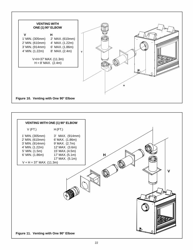
VENTING WITH ONE (1) 90° ELBOW
V (FT.) H (FT.)
1' MIN. (305mm) 3' MAX. (914mm) 2' MIN. (610mm) 6' MAX. (1.86m) 3' MIN. (914mm) 9' MAX. (2.7m) 4' MIN. (1.22m) 12' MAX. (3.6m) 5’ MIN. (1.5m) 15’ MAX. (4.5m) 6’ MIN. (1.86m) 17’ MAX. (5.1m)
17' MAX. (5.1m) V + H = 37’ MAX. (11.3m)
Figure 11. Venting with One 90° Elbow
V H 1' MIN. (305mm) 2' MAX. (610mm) 2' MIN. (610mm) 4' MAX. (1.22m) 3' MIN. (914mm) 6' MAX. (1.86m) 4' MIN. (1.22m) 8' MAX. (2.4m)
V+H=37' MAX. (11.3m)H = 8' MAX. (2.4m)
Figure 10. Venting with One 90° Elbow
VENTING WITHONE (1) 90° ELBOW
V
H
H
V
23
VENTING WITH TWO (2) 90° ELBOWS
V (FT.) H + H1 (FT.)
1' MIN. (305mm) 3' MAX. (914mm) 2' MIN. (610mm) 6' MAX. (1.86m) 3' MIN. (914mm) 9' MAX. (2.7m) 4' MIN. (1.22m) 12' MAX. (3.6m) 5' MIN. (1.5m) 15' MAX. (4.5m) 6' MIN. (1.86m) 17' MAX. (5.1m)
17' MAX. (5.1m) V + H = 37' MAX. (11.3m)
Figure 12. Venting with Two 90° Elbows
VENTING WITH TWO (2) 90° ELBOWS
V (FT.) H (FT.)
1' MIN. (305mm) 3' MAX. (914m)2' MIN. (610mm) 6' MAX. (1.86m)3' MIN. (914mm) 9' MAX. (2.7m)4' MIN. (1.22m) 12' MAX. (3.6m)
17' MAX. (5.1m)NOTE: V + V1 + H = 37' MAX. (11.3m)
VH
H1
H
V
V1
24
VENTING WITH TWO (2) 90° ELBOWS
V H H + H1
1' MIN. (305 mm) 2' MAX. (610 mm) 3' MAX. (914 mm)2' MIN. (610 mm) 4' MAX. (1.22 m) 6' MAX. (1.86 m)3' MIN. (914 mm) 6' MAX. (1.86 m) 9' MAX. (2.7 m)4' MIN. (1.22 m) 8' MAX. (2.48 m) 12' MAX. (3.6 m)
V FT. H + H1 (FT.)1' MIN. (305mm) 2' MAX. (610mm)2' MIN. (610mm) 4' MAX. (1.22m)3' MIN. (914mm) 6' MAX. (1.86m)4' MIN. (1.22m) 8' MAX. (2.4m)
8' MAX. (2.4m)V + H + H1 + 37' MAX. (11.3m)
V
H1
H
V
H1
H
25
Figure 15. Venting with three 90° elbows
VENTING WITH THREE (3) 90° ELBOWS
1' MIN. (305 mm) 2' MAX. (610 mm) 3' MAX. (914 mm)2' MIN. (610 mm) 4' MAX. (1.22 m) 6' MAX. (1.86 m)3' MIN. (914 mm) 6' MAX. (1.86 m) 9' MAX. (2.7 m)4' MIN. (1.22 m) 8' MAX. (2.48 m) 15' MAX. (4.5 m)
8' MAX. (2.48 m) 17' MAX. (5.1 m)V + H + H1 + H2 = 37' MAX. (11.3m)
VENTING WITH THREE (3) 90° ELBOWS
V H H + H1 + H2
1' MIN. (305 mm) 2' MAX. (610 mm) 3' MAX. (914mm)2' MIN. (610 mm) 4' MAX. (1.22 m) 6' MAX. (1.86 m)3' MIN. (914 mm) 6' MAX. (1.86 m) 9' MAX. (2.7 m)4' MIN. (1.22 m) 8' MAX. (2.48 m) 12' MAX. (3.6 m)
8' MAX. (2.48 m) 17' MAX. (5.1 m)V + V1 + H + H1 = 37' MAX. (11.3m)
VENTING WITH THREE (3) 90° ELBOWS
V1
V
H1
H
H
V
H1
H2
26
VENTING WITH THREE (3) 90° ELBOWS
V (FT.) H (FT.)1' MIN. (305mm) 3' MAX. (914mm)2' MIN. (610mm) 6' MAX. (1.86m)3' MIN. (914mm) 9' MAX. (2.7m)4' MIN. (1.22m) 12' MAX. (3.6m)
17' MAX. (5.1m)NOTE: H + H1 = 17' MAX. (5.1m)
V + V1 + H + H1 = 37' MAX. (11.3m)
VENTING WITH THREE (3) 90° ELBOWS V (FT.) H + H1 (FT.)
1' MIN. (305mm) 3' MAX. (914m)2' MIN. (610mm) 6' MAX. (1.86m)3' MIN. (914mm) 9' MAX. (2.7m)4' MIN. (1.22m) 12' MAX. (3.6m)
17' MAX. (5.1m)NOTE: V + V1 + H + H1 = 37' MAX. (11.3m)
Figure 16. Venting with three 90° elbows
V1
H1 HV
H1
H
V1
V
27
! WARNING: A 3/8 INCH (9.5 MM) BEAD OFSTOVE CEMENT MUST BE PLACED AROUND
THE 5 INCH (127 MM) FIREPLACE STARTING COL-LAR BEFORE ATTACHING THE FIRST VENT COM-PONENT. FAILURE TO SEAL THIS JOINT MAYCAUSE THE FIREPLACE TO OPERATE IMPROPERLY.SEE THE DIAGRAM .
STARTINGCOLLAR
STOVESEALANT
BEAD
1 INCH(25.4mm)
FIRST VENTCOMPONENT
! WARNING: ENSURE THAT THE FIBER-GLASS ROPE GASKET SUPPLIED WITH
THE FIREPLACE SEALS BETWEEN THE FIRSTVENT COMPONENT AND THE OUTER FIREPLACEWRAP.
If the installation is for a termination cap attached directlyto the fireplace, skip to the sections, Install Firestops andVent Termination.
1. Attach the First Vent Component to the Starting Collars
To attach the first vent component to the starting collarsof the fireplace:
• Apply a 3/8 inch (9.5mm) bead of stove cement aroundthe 5 inch (127mm) fireplace starting collar.
• Make sure that the fireplace rope gasket supplied withthe fireplace seals between the first 8-5/8 inch (219mm)vent component and the outer fireplace wrap.
• Lock the vent components into place by sliding the con-centric pipe sections with four (4) equally spaced interiorbeads into the fireplace collar or previously installed com-ponent end with four (4) equally spaced indented sections.
• When the internal beads of each 8-5/8 inch (219mm)outer pipe line up, rotate the pipe section clockwise aboutone-quarter (1/4) turn. The vent pipe is now locked together.
Figure 18. Attaching the First Vent Component to the Starting Collars
!
B. Installing Vent ComponentsAfter determining which set of starting collars will be used(top or rear), follow venting instructions accordingly.
Venting Out the Rear VentRemove the installed rear seal cap from the rear startingcollars by removing screws (see Figure 17). Follow the ventconfiguration tables accordingly.
Remove the insulation from the REAR five inch flue, pullthe heat shield out from outside of the firebox.
WARNING: THE TOP HEAT SHIELD (INSIDETHE FIREBOX) MUST REMAIN ATTACHED IFTHE VENT SYSTEM IS ATTACHED TO THEREAR STARTING COLLARS. SEE FIGURE 17.
Venting Out the Top VentRemove the screws in the top vent collar seal cap and re-move the top vent collar seal cap and insulation inside thetop starting collar (See Figure 17).
Remove the heat shield from inside the TOP five inch fluefrom outside of the firebox.
The glass must be taken off again for positioning the logswhen the unit is finally installed in place and finished aroundit. Re-install the glass door. Attach vent system to the topstarting collars.
WARNING: THE REAR VENT COLLAR SEALCAP MUST REMAIN ATTACHED TO THE REARVENT COLLARS IF THE VENT SYSTEM IS AT-TACHED TO THE TOP STARTING COLLARS.
WARNING: FAILURE TO REMOVE INSULATIONIN THE SET OF COLLARS YOU ARE USINGCOULD CAUSE A FIRE.
WARNING: YOU MUST LEAVE THE INSULATIONIN PLACE IN THE SET OF COLLARS YOU ARENOT USING.
If your vertical vent component is over 10 feet, you maywant to install the vertical baffle (located in the bag containingthe install manual) to improve flame appearance. Centerthe vertical baffle on the 5” flue being used, and with selftapping screws secure the baffle to the inside of the firebox.
Figure 17
Venting Out Rear Venting Out Top
!
!
!
HEATSHIELD
DISCARD INSULATION
andHEAT SHIELD
HEAT SHIELD
DISCARD
andHEAT SHIELD
INSULATION
SEAL CAP
SEALCAP
28
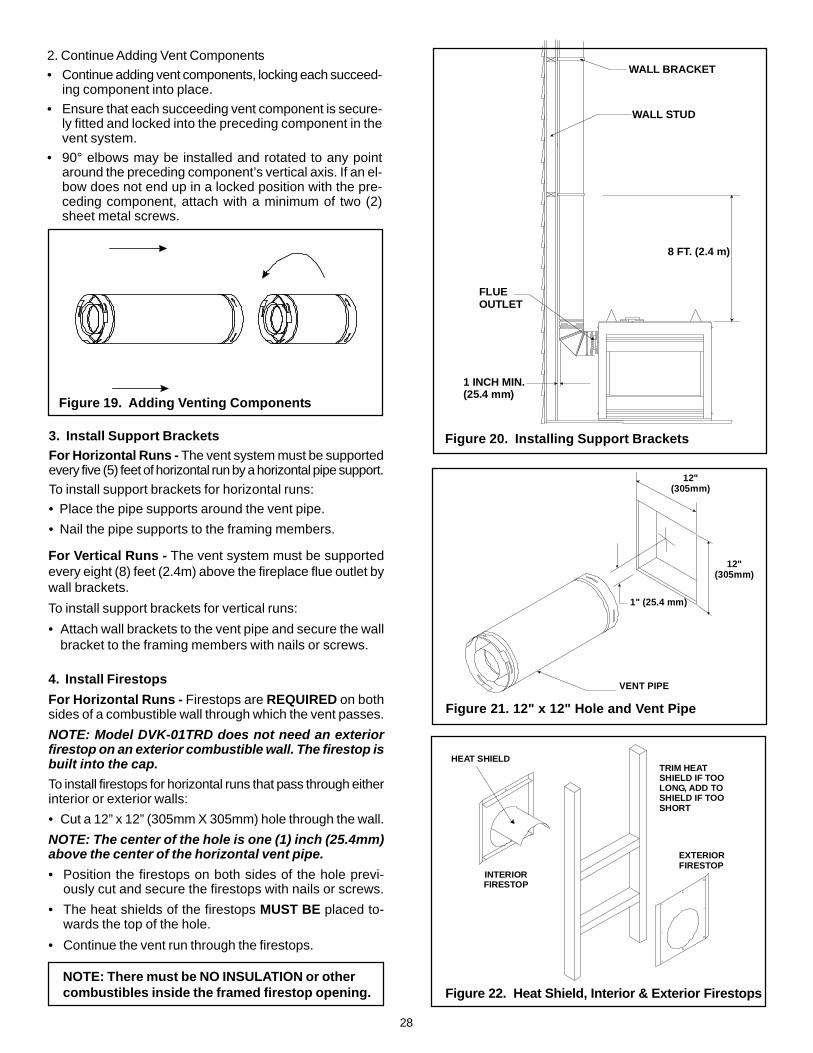
For Vertical Runs - The vent system must be supportedevery eight (8) feet (2.4m) above the fireplace flue outlet bywall brackets.
To install support brackets for vertical runs:
• Attach wall brackets to the vent pipe and secure the wallbracket to the framing members with nails or screws.
4. Install Firestops
For Horizontal Runs - Firestops are REQUIRED on bothsides of a combustible wall through which the vent passes.
NOTE: Model DVK-01TRD does not need an exteriorfirestop on an exterior combustible wall. The firestop isbuilt into the cap.To install firestops for horizontal runs that pass through eitherinterior or exterior walls:
• Cut a 12” x 12” (305mm X 305mm) hole through the wall.
NOTE: The center of the hole is one (1) inch (25.4mm)above the center of the horizontal vent pipe.
• Position the firestops on both sides of the hole previ-ously cut and secure the firestops with nails or screws.
• The heat shields of the firestops MUST BE placed to-wards the top of the hole.
TRIM HEATSHIELD IF TOOLONG, ADD TO SHIELD IF TOOSHORT
EXTERIORFIRESTOP
INTERIORFIRESTOP
HEAT SHIELD
3. Install Support BracketsFor Horizontal Runs - The vent system must be supportedevery five (5) feet of horizontal run by a horizontal pipe support.To install support brackets for horizontal runs:• Place the pipe supports around the vent pipe.
ing component into place.• Ensure that each succeeding vent component is secure-
ly fitted and locked into the preceding component in thevent system.
• 90° elbows may be installed and rotated to any pointaround the preceding component’s vertical axis. If an el-bow does not end up in a locked position with the pre-ceding component, attach with a minimum of two (2)sheet metal screws.
Figure 20. Installing Support Brackets
FLUEOUTLET
1 INCH MIN.(25.4 mm)
8 FT. (2.4 m)
WALL STUD
WALL BRACKET
NOTE: There must be NO INSULATION or othercombustibles inside the framed firestop opening.
29
For Vertical Runs - One ceiling firestop is REQUIRED atthe hole in each ceiling through which the vent passes.
To install firestops for vertical runs that pass through ceilings:
• Position a plumb bob directly over the center of the verti-cal vent component.
• Mark the ceiling to establish the centerpoint of the vent.
• Drill a hole or drive a nail through this centerpoint.
• Check the floor above for any obstructions, such as wir-ing or plumbing runs.
• Reposition the fireplace and vent system, if necessary,to accommodate the ceiling joists and/or obstructions.
• Cut an 11-inch X 11-inch (280mm X 280mm) hole throughthe ceiling, using the centerpoint previously marked.
• Frame the hole with framing lumber the same size as theceiling joists.
Figure 24. Ceiling Firestop (Ceiling Side)
If the area above the ceiling is NOT an attic, position andsecure the ceiling firestop on the ceiling side of the previouslycut and framed hole.
Figure 23. Hole & New Framing Members
If the area above the ceiling IS an attic, position and securethe firestop on top of the previously framed hole.
NOTE: Keep insulation away from the vent pipe at least1 inch (25mm).
Figure 25. Attic Firestop
JOIST
CEILING FIRESTOP
CEILING
NAILS (4 REQUIRED)
CEILING
CEILING FIRESTOP
RAFTER
NAILS (4 REQUIRED)
CEILING
NEWFRAMINGMEMBERS
EXISTING CEILING JOISTS
CHIMNEYHOLE
11" (280 mm) 11" (280mm)
NOTE: There must be NO INSULATION or othercombustibles inside the framed firestop opening.
30
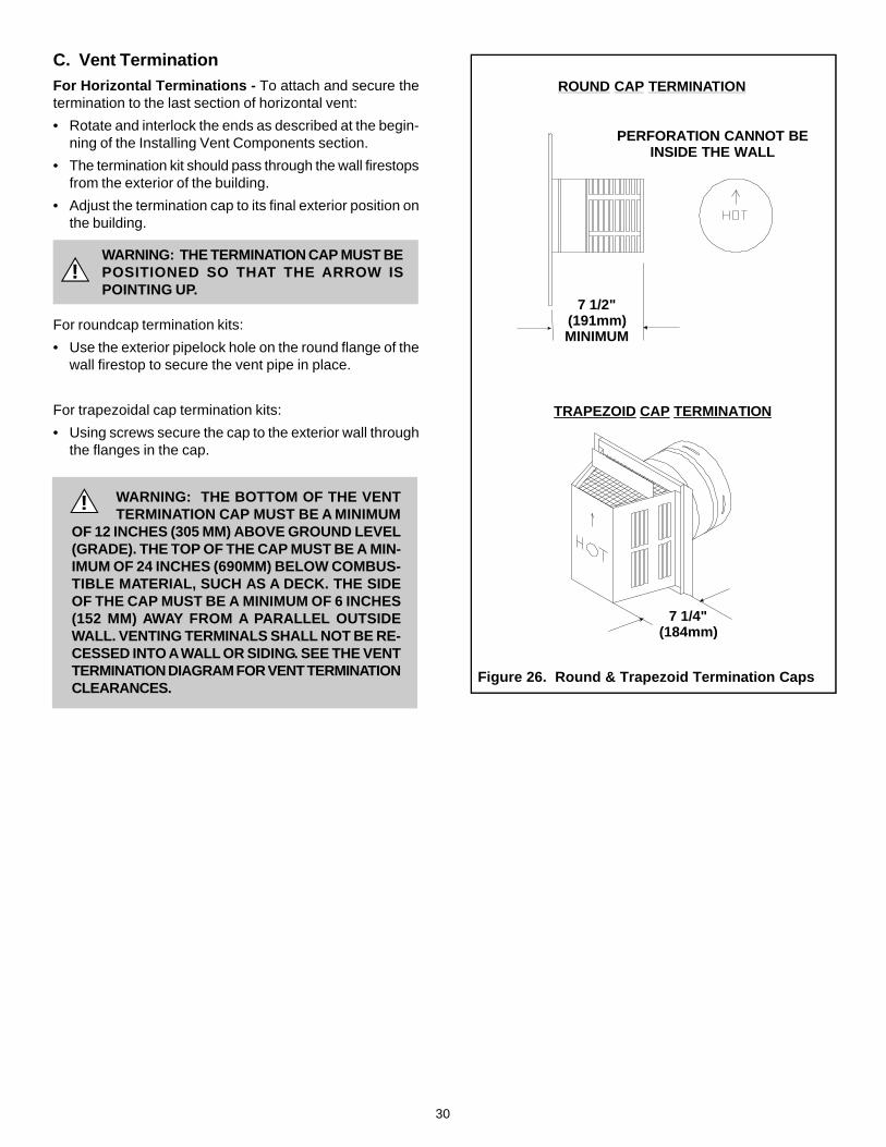
!
C. Vent TerminationFor Horizontal Terminations - To attach and secure thetermination to the last section of horizontal vent:
• Rotate and interlock the ends as described at the begin-ning of the Installing Vent Components section.
• The termination kit should pass through the wall firestopsfrom the exterior of the building.
• Adjust the termination cap to its final exterior position onthe building.
WARNING: THE TERMINATION CAP MUST BEPOSITIONED SO THAT THE ARROW ISPOINTING UP.
For roundcap termination kits:
• Use the exterior pipelock hole on the round flange of thewall firestop to secure the vent pipe in place.
For trapezoidal cap termination kits:
• Using screws secure the cap to the exterior wall throughthe flanges in the cap.
Figure 26. Round & Trapezoid Termination Caps
! WARNING: THE BOTTOM OF THE VENTTERMINATION CAP MUST BE A MINIMUM
OF 12 INCHES (305 MM) ABOVE GROUND LEVEL(GRADE). THE TOP OF THE CAP MUST BE A MIN-IMUM OF 24 INCHES (690MM) BELOW COMBUS-TIBLE MATERIAL, SUCH AS A DECK. THE SIDEOF THE CAP MUST BE A MINIMUM OF 6 INCHES(152 MM) AWAY FROM A PARALLEL OUTSIDEWALL. VENTING TERMINALS SHALL NOT BE RE-CESSED INTO A WALL OR SIDING. SEE THE VENTTERMINATION DIAGRAM FOR VENT TERMINATIONCLEARANCES.
V = VENT TERMINAL X = AIR SUPPLY INLET = AREA WHERE TERMINAL IS NOT PERMITTED
Figure 27. Vent Termination Minimum Clearances
A = 12" ....................... clearances above grade, veran-da, porch, deck or balcony
B = 12" ....................... clearances to window or doorthat may be opened, or to per-manently closed window.
D* = 18" ....................... vertical clearance to ventilatedsoffit located above the terminalwithin a horizontal distance of 2feet (60 cm) from the center-lineof the terminal
E* = 18" ....................... clearance to unventilated soffit
F = 9" ......................... clearance to outside corner
G = 6" .......................... clearance to inside corner
H = 3 ft. (Canada)....... not to be installed above a gasmeter/regulator assembly within3 feet (90cm) horizontally from thecenter-line of the regulator
I = 3 ft. (U.S.A.)6 ft. (Canada) ....... clearance to service regulator
vent outlet and electric service
J = 9" (U.S.A.)12" (Canada) ......... clearance to non-mechani-
cal air supply inlet to build-ing or the combustion air in-let to any other appliance
K = 3 ft. (U.S.A.)6 ft. (Canada) ......... clearance to a mechanical
air supply inletL** = 7 ft. ......................... clearance above paved
sidewalk or a paved drivewaylocated on public property
M*** = 18" ......................... clearance under veranda,porch, deck or balcony
N = 6” ........................... non-vinyl siding12” ......................... vinyl siding
O = 18” ......................... non-vinyl soffit and overhang60” ......................... vinyl soffit and overhang
P = 8 ft.
DE
BL
v
v v
v
v
v
v
v
BB
A H
MX
J or K
I
A
G
F
U.S.(3 FT)B
CAUTION: IF EXTERIOR WALLS ARE FINISHED WITH VINYL SIDING, IT IS NECESSARY TO INSTALL THE VINYL PROTECTORKIT TO THE TOP OF THE EXTERIOR FIRESTOP (FOR ALL ROUND TERMINATION CAPS). IT IS STRONGLY RECOMMENDEDWHENEVER POSSIBLE TO USE THE VINYL PROTECTOR KIT.
* 60” minimum for vinyl clad soffits.
** a vent shall not terminate directly above a sidewalk or paveddriveway which is located between two single family dwellingsand serves both dwellings.
*** only permitted if veranda, porch, deck or balcony is fully open ona minimum of 2 sides beneath the floor.
NOTE 1: On private property where termination is less than 7 feetabove a sidewalk, driveway, deck, porch, veranda or balcony, use ofa listed cap shield is suggested.
NOTE 2: Termination in an alcove space (spaces open only on one sideand with an overhang) are permitted with the dimensions specified forvinyl or non-vinyl siding and soffits. 1. There must be 3 feet minimumbetween termination caps. 2. All mechanical air intakes within 10 feetof a termination cap must be a minimum of 3 feet below the terminationcap. 3. All gravity air intakes within 3 feet of a termination cap must bea minimum of 1 foot below the termination cap.
ON
P
R
Q
(See Note 1)
(See Note 1)
(See Note 2)
NOTE 3: Local codes or regulations may require differentclearances.
NOTE 4: Termination caps may be hot. Consider their proximity todoors or other traffic areas.
WARNING: In the U.S: Vent system termination is NOT permittedin screened porches. You must follow side wall, overhang andground clearances as stated in the instructions.
In Canada: Vent system termination is NOT permitted in screenedporches. Vent system termination is permitted in porch areaswith two or more sides open. You must follow all side walls,overhang and ground clearances as stated in the instructions.
Heat-N-Glo assumes no responsibility for the improper perfor-mance of the fireplace when the venting system does not meetthese requirements.
QMIN RMAX
1 cap 3 feet 2 x Q ACTUAL
2 caps 6 feet 1 x Q ACTUAL
3 caps 9 feet 2/3 x Q ACTUAL
4 caps 12 feet 1/2 x Q ACTUAL
QMIN = # termination caps x 3 RMAX = (2 / # termination caps) x QACTUAL
32
For Vertical Terminations - To locate the vent and installthe vent sections:
• Locate and mark the vent centerpoint on the undersideof the roof, and drive a nail through the centerpoint.
• Make the outline of the roof hole around the centerpointnail.
• The size of the roof hole framing dimensions depend on thepitch of the roof. There MUST BE a 1-inch (25.4mm) clear-ance from the vertical vent pipe to combustible materials.
• Mark the roof hole accordingly.
• Cover the opening of the installed vent pipes.
• Cut and frame the roof hole.
• Use framing lumber the same size as the roof raftersand install the frame securely. Flashing anchored to theframe must withstand heavy winds.
• Continue to install concentric vent sections up throughthe roof hole (for inside vent installations) or up past theroof line until you reach the appropriate distance abovethe roof (for outside terminations).
WARNING: MAJOR U.S. BUILDING CODESSPECIFY MINIMUM CHIMNEY AND/OR
VENT HEIGHT ABOVE THE ROOF TOP. THESE MIN-IMUM HEIGHTS ARE NECESSARY IN THE INTER-EST OF SAFETY. SEE THE FOLLOWING DIAGRAMFOR MINIMUM HEIGHTS, PROVIDED THE TERMI-NATION CAP IS AT LEAST TWO (2) FEET FROM AVERTICAL WALL AND 2-FEET BELOW A HORIZON-TAL OVERHANG.
NOTE: This also pertains to vertical vent systems in-stalled on the outside of the building.
!
Roof Pitch H (min.) ft.
flat to 6/12 1.06/12 to 7/12 1.25over 7/12 to 8/12 1.5over 8/12 to 9/12 2.0over 9/12 to 10/12 2.5over 10/12 to 11/12 3.25over 11/12 to 12/12 4.0over 12/12 to 14/12 5.0over 14/12 to 16/12 6.0over 16/12 to 18/12 7.0over 18/12 to 20/12 7.5over 20/12 to 21/12 8.0
Figure 28. Minimum Height from Roof to Lowest Discharge Opening
To seal the roof hole, and to divert rain and snow from thevent system:
• Attach a flashing to the roof using nails, and use a non-hardening mastic around the edges of the flashing basewhere it meets the roof.
• Attach a storm collar over the flashing joint to form awater-tight seal. Place non-hardening mastic around thejoint, between the storm collar and the vertical pipe.
• Slide the termination cap over the end of the vent pipeand rotate the pipe clockwise 1/4 turn.
HORIZONTALOVERHANG
VERTICALWALL
TERMINATIONCAP
12X
ROOF PITCHIS X/ 12
LOWEST DISCHARGE
OPENING
H (MIN.) - MINIMUM HEIGHT FROM ROOFTO LOWEST DISCHARGE OPENING
2 FT.MIN.
2 FT. MIN.
33
Step 4. Positioning, Leveling, and Securing the Fireplace
• Place the fireplace into position.• Level the fireplace from side to side and from front to
back.• Shim the fireplace with non-combustible material, such
as sheet metal, as necessary.• Secure the fireplace to the framing by nailing or screwing.
!
!
The diagram below shows how to properly position, level,and secure the fireplace.
Figure 29. Proper Positioning, Leveling, and Securing of a Fireplace
Step 5. The Gas Control System
WARNING: THIS UNIT IS NOT FOR USE WITHSOLID FUEL.
Two types of gas control systems are used with these models:Standing Pilot Ignition and Intermittent Pilot Ignition (IPI).
Standing Pilot Ignition SystemThis system includes millivolt control valve, standing pilot,thermopile/thermocouple flame sensor, and piezo ignitor.
WARNING: 110-120 VAC MUST NEVER BE CON-NECTED TO A CONTROL VALVE IN A MILLIVOLTSYSTEM.
NAILING TABS
Figure 30. Gas Control Systems
STANDING PILOT & IPI
! WARNING: CONTINUOUS 110-120 VACSERVICE MUST BE WIRED DIRECTLY TO
THE FIREPLACE JUNCTION BOX IN A IPI SYSTEM.
Intermittent Pilot Ignition (IPI) SystemThis system includes a 3V control valve, electronicmodule and intermittent pilot.
u
34
Figure 31. Gas Supply Line
• Insert insulation from the outside of the fireplace andpack the insulation tightly to totally seal between thepipe and the outer casing.
• At the gas line access hole the gap between the supplypiping and gas access hole can be plugged with non-combustible insulation to prevent cold air infiltration.
Step 6. The Gas Supply LineNOTE: Have the gas supply line installed in accordancewith local building codes by a qualified installerapproved and/or licensed as required by the locality.(In the state of Massachusetts installation must beperformed by a licensed plumber or gas fitter).NOTE: Before the first firing of the fireplace, the gassupply line should be purged of any trapped air.NOTE: Consult local building codes to properly sizethe gas supply line leading to the 1/2 inch(13 mm) hook-up at the unit.
This gas fireplace is designed to accept a 1/2 inch(13 mm) gas supply line.To install the gas supply line:• A listed (and State of Massachusetts approved) 1/2 inch
(13mm) tee-handle manual shut-off valve and a listedflexible gas connector are connected to the 1/2 inch(13mm) inlet of the control valve. NOTE: If substitutingfor these components, please consult local codes forcompliance.
• Locate the gas line access hole in the outer casing ofthe fireplace.
• The gas line may be run from either side of the fireplaceprovided the hole in the outer wrap does not exceed 2” indiameter and it does not penetrate the actual firebox.
• Open the fireplace lower grille, insert the gas supply linethrough the gas line hole, and connect it to the shut-offvalve.
• When attaching the pipe, support the control so that thelines are not bent or torn.
• After the gas line installation is complete, use a soapsolution to carefully check all gas connections for leaks.
WARNING: DO NOT USE AN OPEN FLAMETO CHECK FOR GAS LEAKS.!
Step 7. Gas Pressure Requirements
Pressure requirements for Heat-N-Glo gas fireplacesare shown in the table below.
A one-eighth (1/8) inch (3 mm) N.P.T. plugged tapping isprovided on the inlet and outlet side of the gas control for atest gauge connection to measure the manifold pressure.
The fireplace and its individual shut-off valve must bedisconnected from the gas supply piping system duringany pressure testing of the system at test pressures inexcess of one-half (1/2) psig (3.5 kPa).
The fireplace must be isolated from the gas supply pipingsystem by closing its individual shut-off valve during anypressure testing of the gas supply piping system at testpressures equal to or less than one-half (1/2) psig (3.5 kPa).
USE A WRENCH ONSHUT-OFF VALVEWHEN TIGHTENINGGAS LINE.
MANUALSHUT-OFF
VALVE
FLEX CONNECTOR
GAS VALVE
GAS LINEACCESS CONTROL VALVE
35
Step 8. Wiring the FireplaceNOTE: Electrical wiring must be installed by a licensedelectrician.
CAUTION: DISCONNECT REMOTE CONTROLS IF AB-SENT FOR EXTENDED TIME PERIODS. THIS WILL PRE-VENT ACCIDENTAL FIREPLACE OPERATION.
For Standing Pilot Ignition Wiring
Appliance Requirements
• This appliance DOES NOT require 110-120 VAC to operate.
WARNING: DO NOT CONNECT 110-120 VACTO THE GAS CONTROL VALVE OR WALLSWITCH OR THE APPLIANCE WILL MALFUNC-TION AND THE VALVE WILL BE DESTROYED.
!
Figure 32. Standing Pilot Ignition Wiring Diagram
Figure 33. Fan Wiring Diagram
Optional AccessoriesOptional fan and remote control kits require that 110-120VAC be wired to the factory installed junction box beforethe fireplace is permanently installed.
Wall SwitchPosition the wall switch in the desired position on a wall.Run a maximum of 25 feet (7.8 m) or less length of 18A.W.G. minimum wire and connect it to the fireplace ON/OFF switch pigtails.
CAUTION: LABEL ALL WIRES PRIOR TO DISCONNEC-TION WHEN SERVICING CONTROLS. WIRING ERRORSCAN CAUSE IMPROPER AND DANGEROUS OPERATION.VERIFY PROPER OPERATION AFTER SERVICING.
BLACK S2
ON
OFF
ON/OFFSWITCHWHITE T2
RED T1THERMOPILE
GAS VALUE
BLACK S1
3/16” PIGGYBACK CONNECTOR
THERMOCOUPLE
REMOTE SWITCHPIGTAIL
OPTIONAL WALL SWITCH,THERMOSTAT OR REMOTE
FAN
TEMPERATURESENSOR SWITCH
SPEED CONTROL(RHEOSTAT)
JUNCTION BOX
NOTE: IF ANY OF THE ORIGINAL WIREAS SUPPLIED WITH THE APPLIANCE MUST BE REPLACED, IT MUST BE REPLACED WITH TYPE 105 C RATED WIRE.O
JUNCTION BOX
VARIABLE SPEED CONTROL
TEMPERATURESENSOR SWITCH
WHT
GRN
BLK
BLK
110-120 VAC
BLOWER
BLOWER RECEPTACLEBLK
BLK
BLK
BLK
WHT
GROUND
WHT
BLK
BLK
BLK
36
For Intermittent Pilot Ignition (IPI) WiringAppliance Requirements
This appliance requires that 110-120 VAC be wired to thejunction box. Maintain correct polarity when wiring the junc-tion box.
Operation using Battery Power
This fireplace has an optional battery operation. The sys-tem is fully functional with the use of two “D” size batterieswithout ordinary 110-120 VAC power.
Wiring to the battery pack should be left disconnected inorder to conserve battery life. In the case of a loss of power,simply connect red and black wire leads to activate batterypower (connect red to red, black to black). The fireplacecan be used as necessary. Once power (110 VAC) is re-stored, disconnect red and black wire leads to extend bat-tery life.
Figure 34. Intermittent Pilot Ignition (IPI) Wiring Diagram
Optional Accessories
Optional fan and remote control kits require that 110-120VAC be wired to the fireplace junction box.
Wall Switch
Position the wall switch in the desired position on a wall.Run 16 A.W.G. minimum Romex wire a maximum of 25feet and connect it to the fireplace ON/OFF switch pigtails.
CAUTION: LABEL ALL WIRES PRIOR TO DISCONNEC-TION WHEN SERVICING CONTROLS. WIRING ERRORSCAN CAUSE IMPROPER AND DANGEROUS OPERATION.VERIFY PROPER OPERATION AFTER SERVICING.
WALL SWITCH
RE
D
BLK
IGNITION MODULE 3 VACTRANSFORMER
3 VAC
BRN
BRN
GRN
OR
G
VALVE
OPTIONALBATTERY BACKUP
JUNCTION BOX120 VAC
OPTIONALREMOTE
GROUND TOFIREPLACE
CHASSIS
FANREM
REM FAN
JUNCTION BOX120 VAC
ORG
WHT
I
S
INTERMITTENT PILOT IGNITOR
RE
D
BL
K
IGNITIONMODULE
(3V)
VALVE
ON/OFFWALL SWITCH
LOW VOLTAGE
LOW VOLTAGE
PLUG-IN3V TRANSFORMER
NEUTRAL HOT
GROUND
FLAME SPARKER/SENSOR
OPTIONALBATTERYBACK-UP
REMOTECONTROL
SEE NOTE 1
SEE NOTE 1
FAN OUTLET RECEPTACLE(NO FAN OPTION)
37
Step 9. FinishingFigure 35 shows the minimum vertical and correspondingmaximum horizontal dimensions of fireplace mantels or othercombustible projections above the top front edge of thefireplace. See Figures 4 and 5 for other fireplace clearances.
Only non-combustible materials may be used to cover theblack fireplace front.
WARNING: WHEN FINISHING THE FIREPLACE,NEVER OBSTRUCT OR MODIFY THE AIR IN-LET/OUTLET GRILLES IN ANY MANNER.
!
Figure 35.Minimum Vertical and Maximum HorizontalDimensions of Combustibles above Fireplace
CAUTION: IF JOINTS BETWEEN THE FINISHED WALLSAND THE FIREPLACE SURROUND (TOP AND SIDES)ARE SEALED, A 300° F. MINIMUM SEALANT MATE-RIAL MUST BE USED. THESE JOINTS ARE NOT RE-QUIRED TO BE SEALED. ONLY NON-COMBUSTIBLEMATERIAL (USING 300° F. MINIMUM ADHESIVE, IFNEEDED) CAN BE APPLIED AS FACING TO THE FIRE-PLACE SURROUND. SEE THE DIAGRAM BELOW.
NOTE: Sheetrock or other combustible material suchas wood can be placed on the top edge of the fire-place. A 1/2-inch gap along the side must be main-tained.
Hearth ExtensionsA hearth extension may be desirable for aesthetic reasons.However, ANSI or CAN/CGA testing standards do not requirehearth extensions for gas fireplace appliances.
Figure 36. Sealant Material
ST-TRC
TOP EDGE
SIDE EDGE
PIER-TRC & CORNER-TRC
TOP EDGE
SIDE EDGE
1/2" GAP
1/2" GAP
TOP EDGE OF FIREPLACE
1/2"
12"
CEILING
31”
38
Installing the TrimCombustible materials may be brought up to the specifiedclearances on the side and top front edges of the fireplace,but MUST NEVER overlap onto the front face. The jointsbetween the finished wall and the fireplace top and sidescan only be sealed with a 300° F. (149° C) minimum sealant.
WARNING: WHEN FINISHING THE FIREPLACE,NEVER OBSTRUCT OR MODIFY THE AIR INLET/OUTLET GRILLES IN ANY MANNER.
Install optional marble and brass trim surround kits asdesired. Marble, brass, brick, tile, or other non-combustiblematerials can be used to cover up the gap betweencombustible material (sheetrock or wood) and the fireplace.Do not obstruct or modify the air inlet/outlet grilles. Whenoverlapping on both sides, leave enough space so that thebottom grille can be lowered and the trim door removed.
Positioning the Logs
If the gas logs have been factory installed they should notneed to be positioned. If the logs have been packagedseparately, refer to the instructions that accompany thelogs. Save the log instructions with this manual.
If sooting occurs, the logs might need to be repositionedslightly to avoid excessive flame impingement.
!
Step 10. Installing Trim, Logs & Ember Material Placing the Ember Material
Ember material is shipped with this gas fireplace. The baglabeled Golden Ember (GE-93) is flame colorant material.The bag labeled Glowing Ember (050-721) is standard glow-ing ember material.
To place the ember material:
• Remove the wing nuts and glass clips or tension springsaround the glass door.
• Remove the glass door from the unit.
• Place dime size pieces of ember material about 1/2 inchapart near port holes in burner top. Do NOT press em-bers into burner ports. Cover the top of the burner with asingle layer of ember material. For best performance doNOT place embers on the ports at the rear of the burner.
• Save the remaining ember materials for use during fire-place servicing. The bag of embers provided is sufficientfor 3 to 5 applications.
• Replace the wing nut, glass clips, and screws.
• Replace the glass door and a front trim door on the unit.
• Hand tighten the wing nut.
CAUTION: IT IS STRONGLY RECOMMENDED THATTRIM DOORS WITH OPTIONAL MESH SCREENS BEINSTALLED ON PROPANE MODELS.
Figure 37. Placement of the Ember Material
GLASS SPECIFICATIONS:Large Small Glass
Model Glass Glass TypePIER-TRC 34” x 20” 20” x 20” TEMPEREDST-TRC 34” x 20” N/A TEMPEREDCORNER-TRC’S 34” x 20” 20” x 20” TEMPERED
Heat-N-Glo fireplaces manufactured with tempered glass maybe installed in hazardous locations such as bathtub enclo-sures as defined by the CPSC. The tempered glass hasbeen tested and certified to the requirements of ANSI Z97.1-1984 and CPSC 16 CFR 1202. (Safety Glazing CertificationCouncil SGCC # 1595 and 1597. Architectural Testing, Inc.Reports 02-31919.01 and 02-31917.01.)
This statement is in compliance with CPSC 16 CFR Sec-tion 1201.5 “Certification and labeling requirements” whichrefers to 15 USC 2063 stating “…Such certificate shall ac-company the product or shall otherwise be furnished to anydistributor or retailer to whom the product is delivered.”
Some local building codes require the use of tempered glasswith permanent marking in such locations. Glass meetingthis requirement is available from the factory. Please con-tact your dealer or distributor to order.
___________________________________________
___________________________________________
___________________________________________
Shutter Settings
NG LP
PIER-TRC 1/2” SET
ST-TRC 1/2” SET
L&R CORNER-TRC 1/2” SET
39
!
!
Step 12. Lighting the Fireplace
You’ve reviewed all safety warnings, you’ve checked thefireplace for gas leaks, you know the vent system isunobstructed, and you’ve checked for faulty components.Now you’re ready to light the fireplace.
WARNING: PLEASE REFER TO THE USER’SMANUAL FOR ALL CAUTIONS, SAFETY, AND
WARNING INFORMATION PERTAINING TO THELIGHTING AND OPERATION OF THE FIREPLACE.
After the Installation
LEAVE THIS INSTALLATION MANUAL WITHTHE APPLIANCE FOR FUTURE REFERENCE.
Step 11. Before Lighting the Fireplace
Before lighting the fireplace, be sure to do the following:
Remove all paperwork from underneath the fireplace.
Review safety warnings and cautions
• Read the Safety and Warning Information section atthe beginning of this Installers Guide.
Double-check for gas leaks
• Before lighting the fireplace, double-check the unit forpossible gas leaks.
Double-check vent terminations and front grilles forobstructions.
• Before lighting the fireplace, double-check the unit forpossible obstructions that could be blocking the vent ter-minations or the front grilles.
Double-check for faulty components
• Any component that is found to be faulty MUST BE re-placed with an approved component. Tampering with thefireplace components is DANGEROUS and voids all war-ranties.
A small amount of air will be in the gas supply lines. Whenfirst lighting the fireplace, it will take a few minutes for thelines to purge themselves of this air. Once the purging iscomplete, the fireplace will light and will operate normally.
Subsequent lightings of the fireplace will not require thispurging of air from the gas supply lines, unless the gasvalve has been turned to the OFF position, in whichcase the air would have to be purged.
NOTE: The fireplace should be run 3 to 4 hours on the initialstart-up. Turn it off and let it cool completely. Remove andclean the glass. Replace the glass and run the fireplace foran additional 8 hours. This will help to cure the chemicalsused in the paint and logs.
40
Maintaining and Servicing Your Fireplace
Fireplace MaintenanceAlthough the frequency of your fireplace servicing and main-tenance will depend on use and the type of installation, youshould have a qualified service technician perform an appli-ance check-up at the beginning of each heating season.See the table below for specific guidelines regarding eachfireplace maintenance task.
IMPORTANT: TURN OFF THE GAS BEFORE SERVICINGYOUR FIREPLACE.
Replacing old ember materialFrequency: Once annually, during the checkup.By: Qualified service technician.Task: Brush away loose ember material near the burner.Replace old ember material with new dime-size and shapepieces of Golden Ember (GE-93) and Glowing Ember (050-721). New ember material should be placed alternately ontop of the burner - a layer of Golden Ember, a layer ofGlowing Ember, and so on. Save the remaining embermaterial and repeat this procedure at your next servicing.For more information, see Placing Ember Material.
Cleaning Burner and ControlsFrequency: Once annually.By: Qualified service technician.Task: Brush or vacuum the control compartment, fireplacelogs and burner areas surrounding the logs.
Checking Flame Patterns, Flame HeightFrequency: Periodically.By: Qualified service technician/Home owner.Task: Make a visual check of your fireplace’s flame patterns.Make sure the flames are steady - not lifting or floating.See Figure 38. The flame sensor (DSI) or thermopile/thermocouple (standing pilot) tips should be covered withflame. See Figure 30.
Figure 38. Burner Flame Patterns
MAKE SURE THE FLAMESARE STEADY—NOTLIFTING OR FLOATING.
Checking Vent SystemFrequency: Before initial use and at least annuallythereafter, more frequently if possible.By: Qualified service technician/Home owner.Task: Inspect the external vent cap on a regular basis toensure that no debris is interfering with the flow of air. Inspectentire vent system for proper function.
Cleaning Glass DoorFrequency: After the first 3 to 4 hours of use. As neces-sary after initial cleaning.By: Home owner.Task: Remove and clean glass after the first 3 to 4 hours ofuse. After the initial cleaning, clean as necessary, particu-larly after adding new ember (flame colorant) material. Filmdeposits on the inside of the glass door should be cleanedoff using a household glass cleaner. NOTE: DO NOT handleor attempt to clean the door when it is hot and DONOT use abrasive cleaners.