•' FR-18046-3 12 DECEMBER 1984 L ;_. DESIGN AND ANALYSIS REPORT FOR THE RL10-11B BREADBOARD 'i LOW THRUST ENGINE 1 FINAL REPORT 1 __ CONTRACT NAS3-24238 l ! !: Prepared for " _: National Aeronautics and Space Administration " i Lewis Research Center , t i. 21000 Brookpark Road _: ,: Cleveland, Ohio 44135 k , t Prepared by United Technologies Corporation Pratt & Whitney Government Products Division P.O. Box 2691, West Palm Beach, Florida 33402 UNITED TECHNOLOGIES PRATT&WHITNEY Prltlled in lhQ UntllKI SIIIIII of A ' https://ntrs.nasa.gov/search.jsp?R=19850010710 2018-05-14T04:56:07+00:00Z
Transcript
/
•' FR-18046-3
12 DECEMBER 1984
L
;_. DESIGN AND ANALYSIS REPORTFOR THE RL10-11B BREADBOARD
'i LOW THRUST ENGINE
1
FINAL REPORT1
__ CONTRACT NAS3-24238l!
!: Prepared for "_: National Aeronautics and Space Administration "
i Lewis Research Center , ti. 21000 Brookpark Road _:
The followingindividualshaveprovidedsignificantcontributionsinthepreparationofthisreport.
James R. Brown: Robert R. Foust
Donald E. GallerPaul G. KanicThomas D. Km;_¢Charles D. LimerickRichard J. PeckhamThomas Swartwout
ii
1985010710-002
Pratt & WhitneyFR- 18046-3
SUMMARY
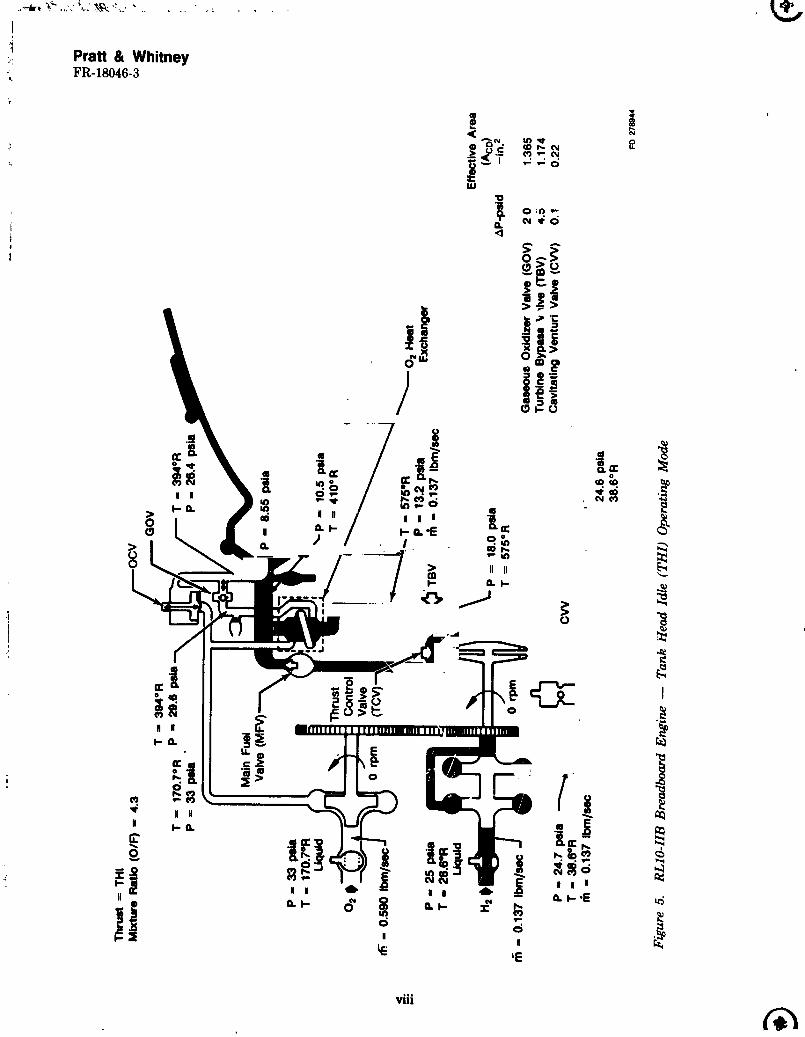
The breadboard low thrust RL10-IIB engine is shown in Figures I through 4. The steady-
state cycle analysis data and schematics shown in Figures 5 and 6. The breadboard engine
utilizes a three stage oxygen heat exchanger (OHE) and four open-loop, hydraulically-actuatedbreadboard control valves, which were adapted from earlier throttling engine programs. The
steady state and transient RL10-IIE engine cycle analyses shown in Section III were based on
anticipated flight propellant inlet pressures of 20 psia for both fuel and oxidizer in order to
provide data for the "flight representative" valves and OHE designs. The first engine test series
using the breadboard design will be performed at fuel and oxi,iizer inlet pressures of 25 psia and
33 psis respectively, because the Pratt & Whitney (P&W) E-6 test stand cannot currentlyprovide the flight-representative inlet conditions. Sections IV and V provide the design/analyses
of the OHE and the breadboard valves, respe_ively.
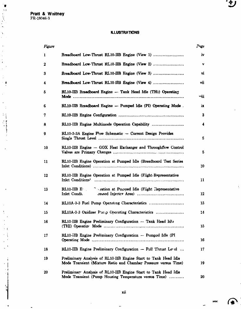
18 RL10-IIB Engine Preliminary Configuration -- Full Thrust Le, el ... 17
19 Preliminary Analysis of RL10-IIB Engine Start to Tank Head IdleMode Transient (Mixture Ratio and Chamber Pressure versus Time) 19
20 PreliminalT' Analysis of RL10-IIB Engine Start to Tank Head IdleMode Transient (Pump Housing Temperature versus Time) ........... 20
xii
1985010710-011
Pratt & WhitneyFR-18046-3
ILLUSTRATIONS(Continued)
Figure Pa_
21 Preliminary Analysis of RL10-IIB Engine Start to Tank He_d IdleMode Transient (Oxidizer and Fuel Flowrates versus Time) ........... 21
22 Preliminary Analysis of RL10-IIB Engine Start to Tank Head IdleMode Transient (Oxidizer Injector Inlet Temperature and FuelTurbine Inlet Temperature versus Time) .................................... 22
23 Preliminary Analysis of RL10-IIB Engine Tank Head Idle toPur-ped Idle Mode Transient (Fuel Pump Speed, Mixture Ratio, _ndCha__berPr_ss,_e versus Time} ................................................ 23
24 Preliminary Analysis of RL10-IIB Engine Tank Head Idle toPumped Idle Mode Transient (Oxidizer Flowrate, Fuel Flowmte,andThrust Level versus Time) ....................................................... 24
25 Preliminary Analysis of RL10-IIB Engine Tank Head Idle toPumped Idle Mode Transient (Oxidizer Injector h 'et, Fuel Injvctor,and Turbine Inlet Temperature versus Time) .............................. 25
B-2 Operation of RL10-IIB Engine During Tank Head Idle Transient .... B-5
B-3 Heat Transfer Model Simulates Thermal Conditions of Components: and Fluids ............................................................................ B-8
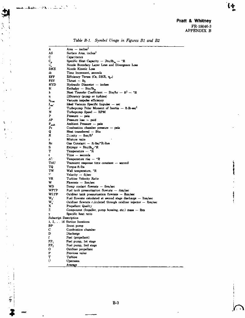
B-1 Symbol Usage in Figures B1 and B2 ......................................... B-3
xviii
1985010710-017
Pratt & Whitney,_, FR-18046-3
J
: _" SECTION I: INTROOUCTION
J
, This report describes the breadboard low thrust RL10-Im engine which is scheduled fort testing in early 1984. A summary is alsoprovided of the analysis and design effort which has been
completedto define the multimode thrust concept applicableto the anticipated requirements for" upper stage vehicles in the late 1980s. Baseline requirements wele establkhed early in the: currentprogramforoperation of the RL10-IIB engine at the following conditiom: 1) Tank Head
Idle (THI) at low propellant tank pressures, without vehicle propellant conditioning or settling•# thrust, 2) Pumped Idle (PI) at a 10% thrust level for low "G" deployment and/or vehicle tank' pre_m_tion, and 3) full thrust (FT) (15,000 lb). Several variations of the engine configuration
wereinvestilpttedand results of the analyses are also included in this report.
"t
J
1985010710-018
Pratt & Whitney_ _ FR-Z8046-3
'. SECTION IIDEFINITIONAND REQUIREMENTS
The RL10-IIB engine (Figure 7) is derived from the basic RL10A-3-3 but has increasedperformance and operating flexibility for use in the Orbit Transfer Vehicle (OTV). With a
' nominal full thrust level of 15,000 lb (in vacuum) at a mixture ratio of 6.0:1, and multi-modeoperational capability as shown in Figure 8, the IIB engine is defined as an RL10A-3-3 with the
following changes:
" 1. Two-position eztendible nozzle with recontoured primary section to give alarge increase in specific impulse with an engine installed length of 55inches.
- 2. Injector reoptimized foroperation at a full thrust level mixture ratio of 6.0:1.
, ! 3. Tank head idle (THI) capabilities, where the engine is run without itsturbopump rotating but pressure-fed on propellants supplied from the :
: vehicle tanks at saturation pressure. Propellant conditions at the engine
L inlets can vary from superheated vapor, through mixed phase, to liquid. Theobjectives are to supply low thrust to settle vehicle propellants and also toobtain useful impulse from the propellants used to condition the engine and
; vehicle feed system.
5 4. Operation at low thrust in pumped mode (maneuver thrust) to provide low ,_,. AV andautogenoustankpressurizationcapability.
5. Capability forboth H2and 0 2 autogenous tank pressurization. ,:
Figure 9 shows an engine flow schematic for the current RL10A-3-3A engine, and Figure 10
for the IIB engine. The fuel pump interstage cooldown valve is deleted, since the engine is
conditioned by running in THI mode. A GO 2 heat exchanger, GO 2 control valve, turbine bypass !valve and cavitating venturi valve are added to enable the engine to run in THI and PI. Fuel and
oxidizer tank pressurization valves are added to give autogenous tank pressurization capability. ._Additional solenoid valves and modifications to the oxidizer control valve and thrust control
valve give the engine its capability to operate in three modes. A dual exciter gives improved
ignition reliability in THI. The primary nozzle is recontoured and a jackscrew-operated, two-
position, dump-cooled extendible nozzle is added. The primary nozzle exit diameter is fixed at 40
in., since this is the limiting diameter for the extendible nozzle to be retract,_._,over the engine'spower head, and is also the largest size which allows insta!lation with a truncated extendible
nozzle in P&W/GPD E-6 test stand. The injector is reoptimized to give improved performance ata mixture ratio of 6.0.
B. OPERATION
1. Tank Head Idle (THI)
The engine is started in THI mode, with propellants supplied in vapor, mixed, or liquidphases.
4
1985010710-020
¢£PraU & Whitney
FR-I_)_-3
OxidizerFlowControl
LiquidFuel PumpInteretage 02CooldownValve Heat
Uquid Exchanger
H20
Fuel PumpDischargeCooldownValve
FD 280486
Figure 9. RLIO-3-3A Engine Flow Schematic -- Current Design Provi 'es Single Thrustravel
OxidizerControl %? lI,-- GaseousVa;v;-_p X Oxidizer
,I
• I•,ro., [.LI 'Control_ I_l-,urbin.I Exchenger !
Valve H2-__r.
H2 Pressure / '---'-Relief Valve--/
FD 280487
Figure 10. RLIO-IIB Engine -- GOX Heat Exchanger and Throughflow Control Valves arePrimary Changes
With the inlet shutoff valves open, fuel flows through the pump, the thrust chamber coolingjacket, around the turbine, through the GO2 heat exchanger, and into the main injector.Similarly, the oxzdizer flows through the pump, and with the oxidizer control valve shut, all theflow goes through the heat exchanger to the injector.
5
=c (,%,
1985010710-021
I, Pratt & Whitney
_i FR-18046-3
4J
2. Pumped Idle (PI)
! After pump conditioning has been completed in THI mode, the engine is ready to be
it operated its pumped idle thrust level for low AV maneuvers or as a step on its acceleration to fullthrust. To start the turbopumps, the main fuel shutoff valve is opened, and the turbine bypass
valve is closed momentarily to give a high initial turbine torque and is then reopened to the
maneuver-thrust position. The cavitating venturi is decreased in area to isolate the fuel pump
from jacket bo_ling instabilities.
3. Full Thrust (FT)
The engine is accelerated to full thrust by closing the turbine bypass valve, opening the
liquid oxidizer valve, closing the gaseous oxygen valve, and opening the cavitating venturi valve.At about 90% of full thrust, the thrust control valve opens to reduce thrust overshoot.
i
I
!I
i4
t: I
|
i 1I
t
6
1985010710-022
°4 _ J
Pratt & WhitneyFR-18046-3
SECTION III_.NGINE CYCLE ANALYSIS
The RLI0-1IB rocketenginemulti-modeoperationanalysisand designaddressedinthis
(THI) and pumped idle(PI)modes of operation.These RLI0 enginemodelsrequiredactive
controls to obtain moderately stable low thrust operation. The 55 inch long, RL10 Derivative IIB
engine concept, defined in the early 1970s, was required to be caps _ ie of stabi(e operation at THI,25% PI and full thrust (FT) using an oxidiz2r heat exchanger (OHE) and simple, solenoid-
actuated engine valves instead of active controls. These analyses of RL10 Derivative II engines,conducted during the 1970-1973 period, included Derivative IIB thrust chamber heat transfer
predictions, thermal skin OHE performance requirements, definition for stable PI operation at
10% thrust with fixed position valves. Both steady state and transient cycle simulations were iincluded in these Derivative Engine Study results as reported in P&W Report No. FR-6011, L
dated 15 December 1973, under contract NAS8-28989. Later analyses were reported in the P&WSpace Tug Engine Report, P&W Report No. FR-7498, dated 21 May 1976 under contract NAS_._-31151, and an Orbital Transfer Vehicle (OTV) engine study P&W Report No. FR-14615, dat_cl15 March 1981, under contract NAS8-33657. All of the background data from these, studies were
reviewed for applicability and documentation to prevent duplication of effort during this RL10- _IIB design and analysis program under NASA contract NAS3-22902.
The evolution of the RL10-IIB engine cycle during this design/analysis program, urder the
Product Improvement Program (PIP), is shown on Table 1. The engine was derived from the 4 ';RL10A-3-3 engine, and modifications were made as required to satisfy the particular goals and
operating conditions for the RL10-IIB engine. The initial configuration shown, which had beencarried forward to this program from earlier analyses, had a pumped idle thrust level of 25% of _
FT. Table 1 also presents characteristics of the Preliminary Fngine Design, an AlternativeDesign, the Baseline Design (which was used for Flight Representative control_, and OHE
performance predictions), and the Breadboard Design intended to be used for the 1st Test Series. i '_These analyses were required primarily because of the 10% PI thrast-level selected f)r the RL10- J
IIB engine and changes identified by the series of hardware design/analyses.
A. PRELIMINARY CONFIGURATION
Preliminary RL] 0-IIB engiz_e steady state cycle analyses defined the operating characteris-
tics, engine configuration requirements, and control valve requirements at low thrust usingestimated performance for an oxygen heat exchanger at the 10% thrust PI design point identifiedat the start of this effort. The RL10 Derivative Engine steady-state cycle deck MF2277 described
in Appendix A was modified to provide the 10% thrust PI sir_ulation #ith estimated heatexchanger characteristics. Incorporation of a reduced effective flow area (0.9 in. '2)turbine statorconfiguration, tested extensively during the 1960s, matched the turbine powel to the required10% PI flow rates. Engine operation was investigated using propellant inlet conditions
achievable on the E-6 test stand (Fuel Pump Inlet Pressure (FPIP) = 25 psia, Oxidizer PumpInlet Pressure (OPIP) = 33 psia) for the scheduled breadboard low thrust test series, as well as
with the lower propellant i,_let conditions (FPIP = 20 psia, OPIP = 20 psia) that will be availablefor subsequent low thrust test series. The later propellant inlet conditions are more representa-tive of the expected flight vehicle propellant conditions and will be use_! for the "flight
representative" (FR) component designs and the second engine test series.
Injector l_iector Nozzle OHE Nozzle H2/O2Item Area A_a Heat Heat Area Gear Inlet ApplicableNo. Con[iguration (in. _) (in._) Transfer Transfer (in. 2) Ratio Conditions Figures
_' 1 RL10 A-3-3 0.8 2.25 RL10A-3-3 NA 1.1 2.5 NA NA
8 Final 0.8 2.25 RL10-1IB 3 Stage OHE 0.9 2.1 Flight 65 to 68Baseline Update Update Representative
"reversed flow
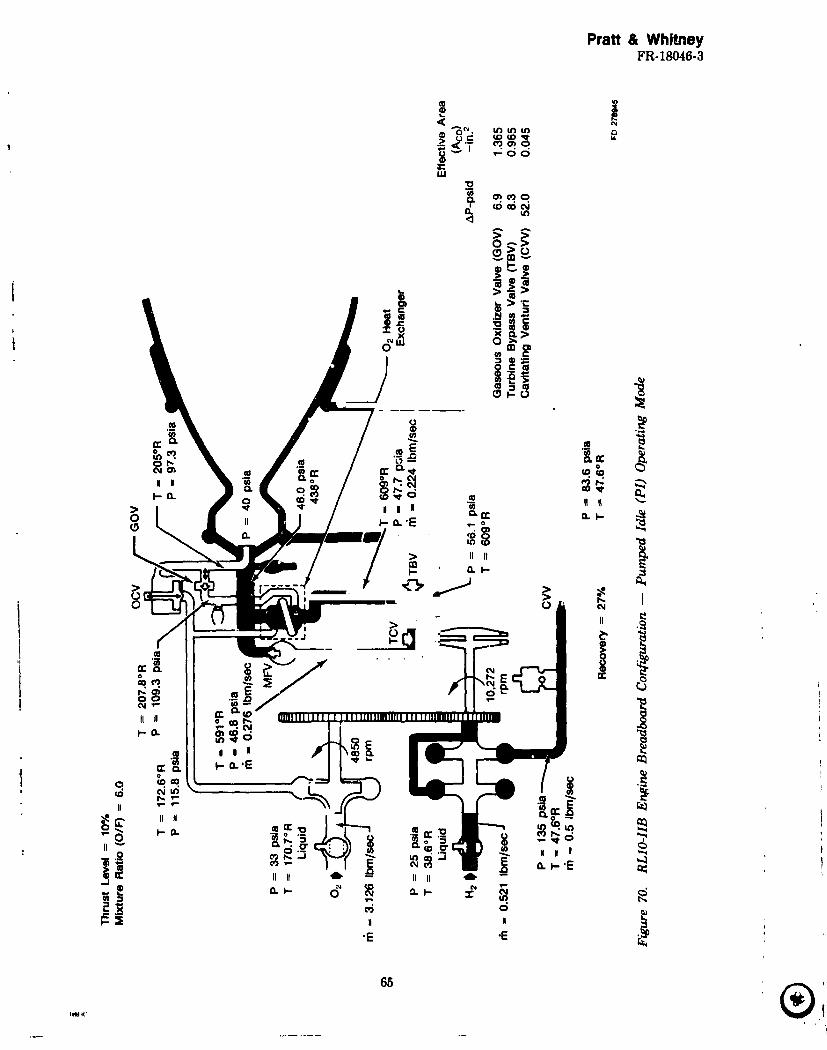
9 Breadboard 0.8 2.25 Final Final 0.9 2.1 Breadboard 69 and 70RL10-IIB Baseline Baseline
NA -- Not Applicable
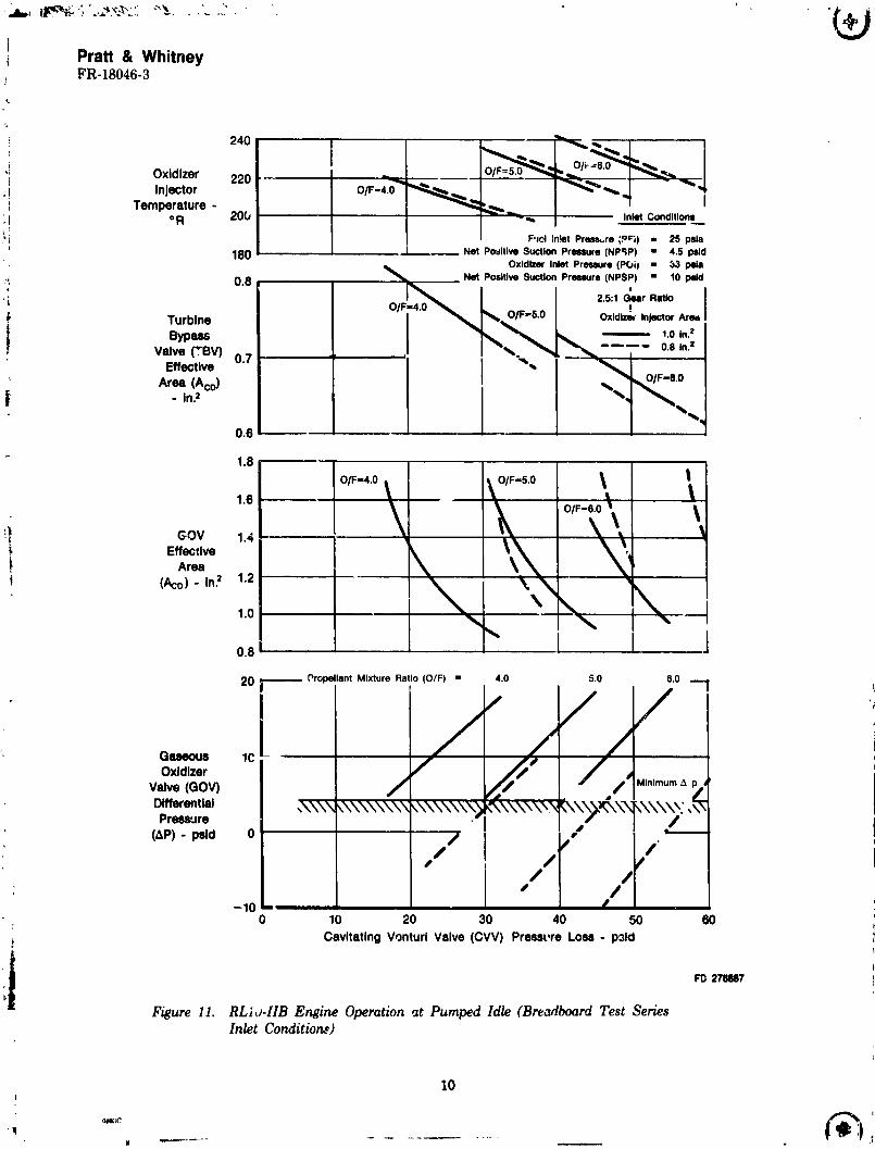
Parametric analyses of requirements for the PI Gaseous Oxidizer Valve (GOV) area andoxidizer injector temperatures as functions of venturi pressure loss _nd mixture ratio are shownin Figure 11 for the breadboard test series inlet conditions. As indicated, marginally acceptablevalve differential pressures (AP's) and oxidi_r injector conditions could be obtained with the
! 0.8 in.2 RL10A-3-3 Bill-of-Material (BOM) oxidizer injector flow area and 2.5 gear ratio.However, increased GOVAP would be available with the oxidizer injector flow area increased to1.0 in.2
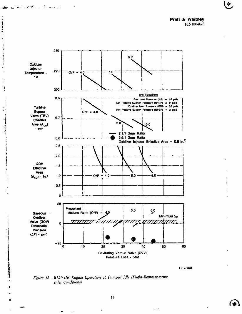
Using the flight-representative inlet conditions showed that PI operation with the 0.8 in.2oxidizer injector area would require a gear ratio change to 2.1 tJ provide acceptable GOV _P(Figure 12). The 2.1 ratio gears had previously been tested on the RLIOA-4 engine. Increasingthe oxidizer injet *$�„area to 1.0 in.2not only increased the control margin, it also providedsatisfactory oxi6i_ferinjector conditions and control valve AP with the 2.5 gear ratio at the flightrepresentative in;et conditions as shown in Figure 13. Incorporatingthe 2.1 gearswould increaseGOVAP margin mrther as indicated. However, the 2.1 gear parts were long-lead items and nonewere available, so continued analysis was concentrated on the 2.5 gears and 1.0 in.2 injectorconfiguration. The 10% *hrust operating points at mixture ratios of 4.0, 5.0, and 6.0 werecomparedon RL10 pump _peratingmaps with test data points (development engine FX141-45)
The RLi0 _IB engine _._)nfi_r," ._ .. ;_ completion of the preliminary analysis is summ_J-
tired as item 3 i_ Table 1. Valve s, _.:, .J,d flow schematics for engine conditions correspondingto the three required operating l,-:':_.!_J(THI, PI, and FT) are shown in Figures 16 through _8. Acomparison of configurations stt_di_:d during the preliminary analysis is presented in Table 2.
Transient analyses were con(',ucted with the computer programs defined in Appendix B
using this preliminary engine configuration t_) provide data for the flight-representative controlvalve designs The transients from start to THI, from THI to PI, and from PI to FT were eachexamined separately. The start-to-THI transients were evaluated with flight represent-.tive inlet
pressures and a combination of both saturated li,?dd and saturated var_r propellants.Preliminary THI transient engine characteristics with satura_:_ I;_,,;,__:,_oeflants are shown in
Figures 19 through 22. As indicated, stJ._ady-state THI operation is achieved in less than 45seconds after start. Preliminary engine characteristics for transient operation from THI to PImode were also generated and critical engine parameters are shown in Figures 23 through 25.Steady-state PI operation is achieved in less than 1 second after initiation of the transient,as shown.
Preliminary RL10-IIB engine transient characteristics from PI (10% thrust) to FT were Ialso defined. Initial engine transient valve scheduling required that the simulated RL10 thrustcontrol valve (TCV) stay closed up to 300 psia chamber pressure, which is normal operation.This required the turbine bypass valve to be ramped closed very slowly (-- 806 msec-- anunreasonable requirement) to ivcrease duration of the transient _nd prevent pump overspeed.Transient characteristics with a more reasonable TBV ramp tim_ (_ 200 msec) produced an
acceleration with unacceptable pump overspeed and thrust overshoot (denoted as squares 9nFigures 26 through 29). Opening the TCV at a chamber pressure of 100 psia produced a moreacceptable transient (denoted as circles on the figures). The complete transient characteristicswere not defined during thi_ preliminary analysis and the simulation was arbitrarily terminated
when chamber pressure reached 300 psia. The selected valve sequencing and flow rates for these*.ransients are presented in Figures 30 thtuugh 32.
B. PRELIMINARY UPDATE CONFIGURATION
An update of the preliminary RL10-IIB engine cycle analysis incorporated results of thethermal analysis of the recontoure£ _nd shortened RL10-IIB thrust chamber/primary nozzleassembly. The new heat transfer characteristics were incorporated into the cycle deck and new
design points at THI, PI, and FT were generated. Flow schematics are shown in Figures 33through 35. Pumped idle (10% thrust) operation at a mixture ratio e¢ 6.0 required a r_uction incavitating venturi pressure loss (Figure 36) to provide the desired conditions at the oxidizerinjector. Control capability on the oxidizer side was diminished because the GOV pressure losswas decreased by 30%. Control capability would ha_,e been reduced further at lower mixture
ratios as it would have been necessary to further decrease the venturi pressure loss to maintaingaseous conditions at the oxidizer injector.
1985010710-025
]Pratt & Whitney
t FR-18046-3
240; P ,O/r =6.0'; Oxidizer220 -- L
;I Injector O/F=4.O'_ __ _ _ "_
i Temperature - _,_ I:t ° R 20b - ,,,, InletConditions
thusprovidingade_luateinjectorpressurelosstoensurestablecombustion.Duringaccelerationi toFT, closingtheGOV causestheoxygentobe routedthroughtheOCV totheinjectorwhere:l_ sufficient i_je:tor differential pressure (Ap) is available for stable operation at FT. However, ai portion of the prdiminary engine acceleration range (between 10% and 40% thrust) may havei insufficien_injector(liquidoxygen)Ap topreventcombustioninstabilitywiththeGOV closed.'_ Therefore, an _lt_rnative configuration was conceived to eliminate this possibility. The heati exchanger was moved to the fuel le.g downstream of the main shutoff valve (Figure 38) so that)
bo_h propellants ';'lowthrough it at all times, thus ensuring sufficient oxidizer injector AP andpote,zt;ally allowing stable engine operation throughout the range from 2% to 100% thrust.
l.I This configuration change would eliminate the liquid oxidizer flow control valve. Ground
i ratio trim and utilization capability would have to be added to themixture propellant gaseous
t oxygen valve (GOV). Then, to accommodate the full thrust (FT) gaseous ozyge:l flow, theinjector's effective area would have to be increased. Initially, an area of 2.0 in. 2 was nvastigated,
i butthisarearesultedina marginalfuelpump stallmargin.Therefore,toincreasef_Jelpump stallmargin,theareawas furtherincreasedto3.0in.2To maximizecozrbustorefficiency,thevelocity
of the gaseous hydrogen into the chamber was also increased to match the velocity increase that
resulted from gaseous oxygen injection at FT. This was achieved by decreas:ng the fuel injectoreffective area by approximately 25% to 1.7 in. 2 To ensure adequate pressure loss on the oxidizer
j side(forcontrolpurposes)and tomove thefuelpump operationaway from thestallline,theI H2/O 2 pump gear ratio was reduced from 2.5 to 2.1. Pump operating parameters at 10% thrust
level are presented in Figures 39 and 40. The effects of varying the mixture ratio and cavitating i
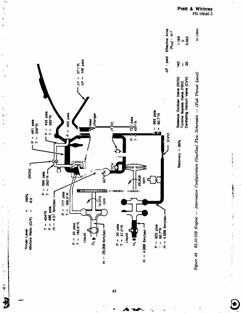
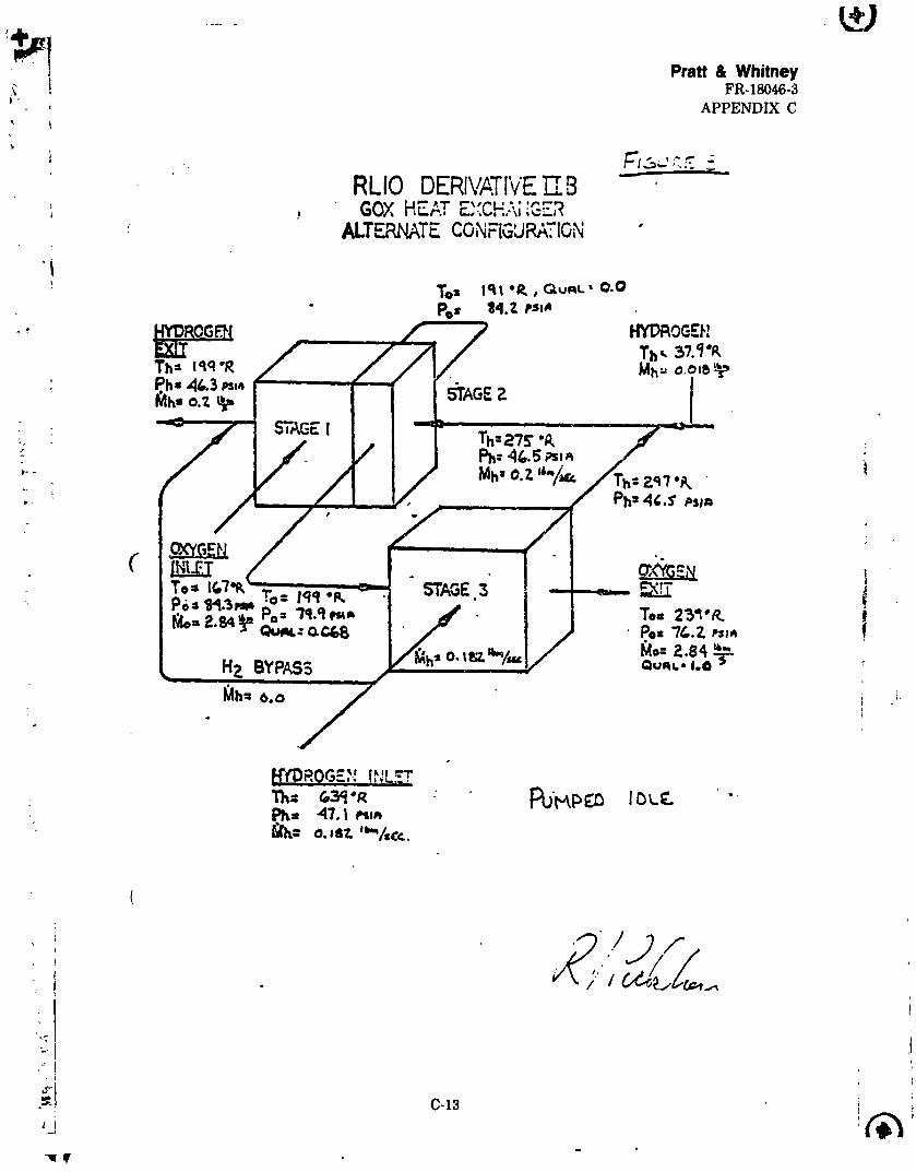
venturiAP on the 10% thrustoperationareshown in Figure41.Enginecyclepointsforthis ialternative (gas/gas) configuration are shown in Figures 42 through 44. Table 3 compares the |preliminary configuration with this alternative configuration. ."
D. BASELINE CONFIGURATION
A proposal to build the alternative configuration for testing was rejected because of the
significant changes to engine hardware and operations experience not related to low thrust irequirements, however the option to implement it later was left open. The same oxygen-hydrogenheat exchanger design requirements apply to either of the low thrust engine configurations. The2,1:1 gears, however, offer benefits to both the gas/liquid and gas/gas versions of the engine, so adecision was made to incorporate the gears into the gas/liquid engine. These gears also allow the
oxidizer injector area to be re_luced to 0.8 in. 2 -- the same area as in current RL10A-3-3Aproduction engines. Flow schematics for the resultant "baseline" engine configuration designpoints at THI, PI, and FT are presented in Figures 45 through 47.
engine3-stageoxidizerheatexchanger(OHE),suchas shown inFigure48.The resultantcycledata are shown in Figures49,50, and 51 forTHI, 10% thrust,and FT operatinglevels,
"_i-- Figure 41. RLIO-IIB Alternative Configuration Cycle Deck Results
40
1 -'" (_)w ......
1985010710-056
t
Pratt & Whitney :FR-18046-3
1
Pratt & Whitney_,; FR-18046-3
Pratt & WhitneyFR-18046-3
Pratt & WhitneyFR-18046-3
Table 3. Comparisonof the RLIO-IIB Engine Preliminary Configuration Withthe Alternative Configuration
Preliminar_ AlternativeOperating Range -- % Full Thrust 2 to 10, 40 to 100 2% -- 100%Oxidizer Control Valve Yes NoGear Ratio 2.5 2.1Fuel Injector Area -- in.2 2.25 1.7Oxidizer Injector Area -- in.2 1.0 3.0GOX HEX Used -- % Full 2 to 10 2 to 100ThrustStart Transient Rapid Pc Rise Smooth and Clean Pc
: A subroutine that approximates the thermal ine,tia of the OHE was then incorp_.rated into
the engine transient compute: _.:,nulation. The model incorporates the effects on propellan_
temperatures of the heating or .ooling of the mass of metal i, the OHE. The one-dimensionalmodel of heat flow to and from the metal is based on a multi-point analysis -f the he._t exchanger
at steady-state conditions. Use of the model _ves a more realistic representation ol transient
parameters. Transients were investigated from THI to PI. Significant engine parameter_ (Pc,
O/F, rpm, and FTIT vs time) are shown in Figures 52 through 55. The transient from PI to lerwas also investiga_<i to determine valve _heduling. The program wa_ run with ramped inputthrust control characteristics b_cause an _ccurate thrust control transient simulation was not
available. Figures 56 through 59 present the same engine parameters listed above versus time.
This acceptable transient was achieved by opening the cavitating venturi and n_dn fuel valve,
allowing the engine to accelera*e to an intermediate thrust level (Pc _ 160 psia) then clo_ing theturbine bypass valve. Thi-_ allowed the gaseous oxygen downstream of the (liquid) OFC t_ be
removed from the system before the transition to ful_ turbine powe_, thus preventing the: excessive fuel pump ove_peed seen on previous transient simulations. (c.f. Figure 27,
Preliminary RL10-IIB Configuration.)
t
,_ 45 "
- 40
?,_ 30 /Chamber 25 I
Pre_mure-i
psla 20 f
10 _ --_,_ -
5
0 J iI
• 0.0 0.1 0.2 0.3 0.4 0.5 0.6 0.7Time from THI to PI - Seconds i
FD 278928
Figur_ 52. RLIO-IIB Engine -- Tank Head Idle to Pumped Idle Transition (Chamber iPressure versus Time)
52
®
1985010710-068
: Pratt & WhitneyFR-18046-3
7.5
7.0
6.5
.oChamber5.5 _ _Mixture
R_.tio 5.0 _ / _,,,,,,jj
,.ol/v
"i 3.5
3.0= 0.0 0.1 0.2 0.3 0.4 0.5 0.6 0,7
Time from THI to PI Signal- SecondsFD278929
Figure 53. RLIO-IIB Engine -- Tank Head Idle ro Pumped Idle Transition (ChamberMixture Ratio versus Tirrr_)
18,000
16,000
14,000
12,000 L
Fuel /
Pump 10,000
Sp_d- 8,1;cOrpm
6,000 /4,000 f
- /
2,ooo _._1/ 100.0 0.1 0.2 0.3 0.4 0.5 0.6 0.7
Time from THI to PI Signal - SecondsFD278930
Fi/,_ure 54. RLIO-!IB Engine -- Tank Head Idle to Pumped Idle Transition (Fuel Pump
Speed versus Time)
'T 53_j_jj (b_q,IC
1985010710-069
Pratt & WhitneyFR-18046-3
675
670
665
660
Turbine 655 f__
,n.Temperature -
oR 650 __645 _"
640
635
630_" 0.0 0.1 0.2 0.3 0.4 0.5 0.6 0.7
Time from THI to PI Signal - Seconds
FD 278931
Figure 55. RLIO-IIB Engine -- Tank Head Idle to Pumped Idle Transition (Turbine Inlet
Temperature versus Time)
450
400 v
350 t'_/"-
Chamber 250Pressure
-psla 200
150 #
lOO
50 ]: o I: 0.0 0.2 0.4 0.6 0.8 1.0 1.2 1.4
Time From PI-to-FTSignal - Second
;, FD 278932
Figure 56. RLIO-IIB Engine -- Pumped Idle to Full Thrust Transition (Chamber Pressureversus Time)
54
1985010710-070
l_ Pratt & Whitney'! FR-18046-3
",t
_- 9
, 8L
7 "
S
6 _ -f
Chamber 5 "'
Ml,_lure fr_ /• Ratio 4
_ 2
; 0.0 0.2 0.4 0.6 0.8 1.0 1.2 1.4
:_ Time From PI-to-FTSignal - Second
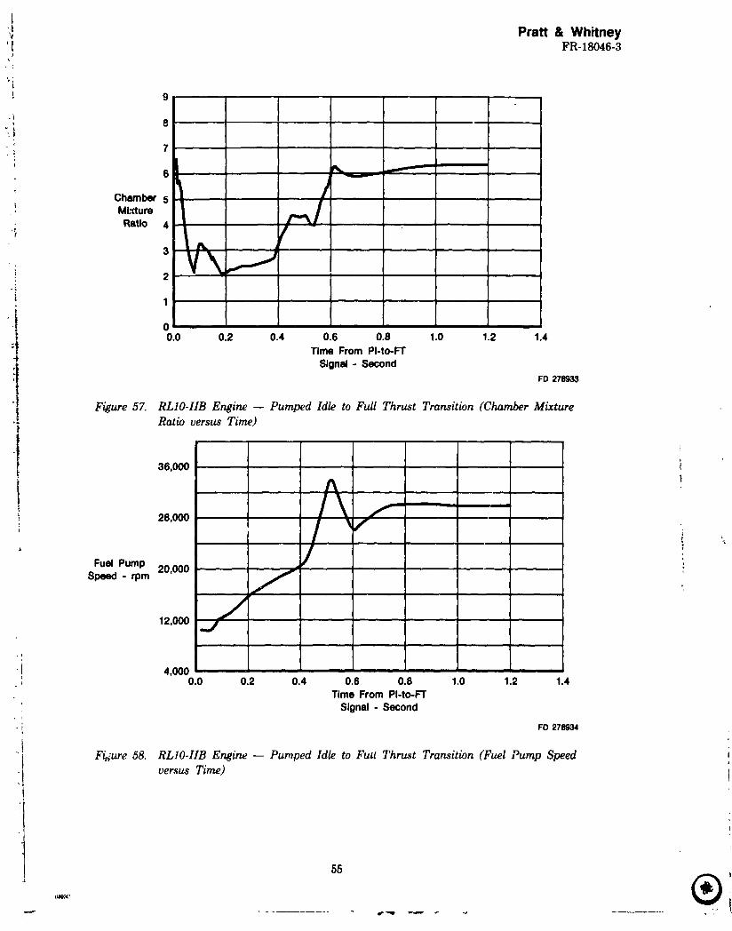
FD 278933
Figure 57. RLIO-IIB Engine -- Pumped Idle to Full Thrust Transition (Chamber Mixture•; Ratio versus Time)
36,000
Fuel Pump 20,000 L.,
Speed - rpm f
/12,ooo.j
4,0000.0 0.2 0.4 0.6 0.8 1.0 1.2 1.4
Time From PI-to-FTSignal - Second
, i
• t FD 278934
Figure 58. RLIO-IIB Engine -- Pumped Idle to Full Thrust Transition (Fuel Pump Speed
i! versus Time)
55
®l_3(' i
1985010710-071
Pratt & WhitneyFR-18046-3
_u
° \520
Turbine Inlet
• ,_ Temperature °R 480
440 _--
40O
360
320-- - 0.0 0.2 0.4 0.6 0.8 1.0 1.2 1.4
Time From PI-to-FTSignal- Second
FD 2711e36
Figure 59. RLIO-IIB Engine -- Pumped Idle to Full Thrust Transition (Turbine Inlet
. Temperature versus Time)
An effort was made to write a thrust control simulation for use in the RL10-IIB engine
transier.t program. The RL10 thrust control valve (TCV) (Figure 60) limits thrust overshoot
during engine start and controls turbopump power to maintain chamber pressure at steady-state.
A spring-mass model and a two-volume dynamic model were combined to simulate the transient
; response of the thrust control. The spring-mass model de_rmines the shear orifice and bypassvalve displacements as functions of time and fluid system driving forces. The two-volume fluid
- dynamics model calculates flows and pressures in the thrust control to determine those forces.
Various iterations of the thrust control si.nulation _ _n with input engine acceleration
test data from P&W experimental engine FX143-33 (Rm, -. 436.01), which had been fitted
with high response instrumentation to measure TCV input parameters. This produced thrustcontrol simulation results that compared faro, ably to engine test data (Figures 61 and 62).
However, when this simulation was used with the RL10-IIB engine transient program, unstable
operation was indicated during engine acceleration to full thrust from pumped idle. Manyi__rations of the basic thrust control simulation ar n a simplified version failed to provide either
engine operahon consistent in all respects with measured data or stable engine operation after
acceleration. ,4 modification to the engine simulation to incorporate a gas venturi between the
fuel bypass tee and turbine inlc _ appeared to reduce the chamber pressure oscillation durationbut did not eliminate it entirely (Figures 63 and 64). Since rated thrust demonstration was not a
primary goal of the first test series, the TCV simulation effort was terminated.
- ®r*- • J J..._mmml
1985010710-072
Pratt & WhitneyFR-1_)46-3
Pratt & WhitneyFR-18046-3
d "
7OO
A!' 600 El
•,,,,-- Calculated _•---- Measured E5OO
!
Servo 400ChamberPressure
" -pals 300 ....
zoo J
= ],, _I I I.._
.,-- _-...... T Ir - 0.0 0.4 0.8 1.2 1.6 2.0 2.4 2.8 3.2
Figure 63. RLZO-IIB Engine Start Transient -- Pumped Idle Operating Mode to FullThrust Level (Chamber Pressure versus Time)
0.35 _']'='_ 1"_ (_i r'
0.30 FI With Gas Veflturl ]l II(_ Without Gas Venturl i
, -o.,o.,o ill, °trO III Valve
,_ Area.ln.2 0.15 I I'I[ _/ _'1 4TI,*''
0.10 ! --v
0.05 J
0.0 _ t _0.0 0.2 0.4 0.6 0.8 1.0 1.2
Time from EngineStart Signal - seconds FO278940
Figure 64. RLIO-IIB Engine Start Transition -- Pumped Idle Operating Mode to FullThrust Level (Thrust Control Valve Area versus Time)
I F. FINAL BASELINE AND BREADBOARD CONFIGURATIONS
After the designs of the flight representative controls and the design and heat transferanalyses of the OHE were completed, the characteristics of the "reversed" flow OHE model(Figure 65) were incorporated in the cycle deck. As explained in Section IV, and Appendix C, ther^verse flow concept permitted reduction in 3rd-stage heat transfer without redesign of the heat
I 59
- ®
1985010710-075
r
Pratt & WhitneyFR-18046-3
exchanger. This became the final configuration. The results are shown in Figures 66 through 68.The cyc._edeck was then run with propellent inlet conditions and corresponding valve settings
planned for the breadboard lcw thrust engine test program. These results are shown in Figures 69and 70.
Mixture Ratio (O/F) = 6.0,. Stage 2 InsulationConductivity= 0.033 Btu/ft-hr°R
The OxidizezHeatExchanger(OHE) heattransferanalysesthatprovidedthebasicOHE
designrequirementsandthoseforsubsequentdesigniterationswerebasedon limitingtheheatinputtotheliquidoxygenduringbothTHI andPIoperationuntila 5% to10% oxidizerquality(percentvaporbyweight)isachieved.Increasedheattransferratescouldthenbeappliedwithoutcausingunstableboiling.TheserequirementshadbeenestablishedduringthetestsandstudiesleadingtotheSpa_ Tug EngineReport(P&W ReportNo.FR-7498,21 Muy 1976),and theOrbitTransferVehicleAdvancedExpanderCycleEnginePointDesignStudy(P&W ReportNo.FR-14615,15March 198D.The maximum allowableheatfluxvaluesfortheliquidox)genatTHI andPIconditio....verecalculatedaccordingly.
The basicRL10-11BOHE designfluidconditionsareshowninTable4.The same inletflowrates,temperaturesandpressuresweremaintainedforallOHE designanalyses.The initialheattransferanalysmdefinedathree-stagecross-flowheatexchanger.Figure71showstheinitialthree-stageheatexchangerarrangementwiththe10% Pumped Idledesignpointperformance
f 1omperature- 'R 6_9.0 --Enthalpy -- Ptu/lbm 2161.0 1822.0 I
The initialOHE wasdesignedtosupplyslightly-superheatedoxygenat209°Rand77.2psia iat the exit. Stages 1 and 2 are of etched or milled-channel stainless steel (Thermal Skin®) !
constru'tion with metal felt insulation between the plates. Stage 3 is of stainless steel Thermal iSki.-,.construction with no insulation between the plates. Detailed geometry and performance '
informatmn for the individual stages can be found MFigures 72 through 74. I
Stage 1 was demgned to assure stable boiling of the liquid oxygen at the conditionsexperienced duri"g THI operation. The metal felt insulation density and thickness were selectedto keep the heat flux to the oxygen below the maximum allowable heat flux for stable boiling(0.95 Btu/ft '_sec) at THI. The calculated conductivity of the compressed metal felt insulationused in the analysis was 0.041 Btu-ft/ft2-hr-°F.
PIC.:.:CZDI)_GPAGI_ BLANK NOT FILMED
"" 67
PA -.INt m NAU.V
• ®
1985010710-082
Pratt & Whitnel,_" FR-i8046-3
.,
Hydrogen ExitTout = 238OR
Pout= 46.4 psla
2 /1 OxygenOxygen Inlet
Tin = 167.3TMPin = 84.3 psla / I T = 199°RIn= 2.84 Ib/sec P = 82.1 psla
" Stage 2 was designed so that no u_table boiling of the liquid would occur at pumped idleflow conditions. It required 40% dense metal fiber insulation between the hydrogen and oxygenplates. This insulation is too stiff to conform to the plate surface and therefore must be brazed tothe plates. The calculated equivalent conductivity of the 0.025 inch thick insulation and braze is0.294 Btu-ft/ft2-hr-°F. The maximum allowable heat flux for stable boiling at PI is 2.62 Btu/ft 2sec. The calculated maximum heat flux for this configuration is 2.41 Btu/ft 2 sec at PI.
Stage3 ofthe OHE was designedto deliver209°R superheatedoxygenat h,ePI design
- ofsingle-phaseflowand two-phaseflowatthePI designpoint.Oxygen single-phaseflowoccursinstage1,thefirsthalfofstage2,and theend ofstage3.Two-phaseoxygenflowoccursinthelasthalfofstage2 and most ofstage3.Two methodswereusedtocalculatethetwo-phaseflow
..
pressuredrops.The homogeneous model is most accurateat low vapor qualitiesand the
: _ separated flow model, with the Martinelli-Lockhart correlation, is more accurate at higherqualities (and also gives higher pressure losses). The total oxygen pressure drops at PI using thehomogeneous and separated-flow models are 4.4 paid and 7.1 psi& respectively. Since theMartineUi-Lockhart separated flow model is the more conservative method, it was used forcalculation of all two-phase oxygen pressure drops.
.- The initialdesignoftheOHE, basedon theaboveanalyses,was a silver-brazedType 347
stainlesssteelcoresand end closures.The calculatedweightofthedesignwas 130pounds (Ref.
OHE was 51 pounds,but therewas reluctanceto make thechangebecauseofthepotentially
more difficultfabrication(verylimitedP&W experiencewithaluminum weldingand brazing).
However, afterweighingthe known risksand benefitsthe decisionwas made to go withaluminum and theredesignwas accomplished(Ref.LayoutDrawing No. L-238388,Sheets5-7).
resultedin unplanned designsupport effortsto determinetheirvalidities.As a result,' modifications to the flow passage groove dimensions and shapes were found necessary through" sample panel etchings to assure producibility for the required flow areas. Flow passage geometry
was revised accordingly.
Also, conductivity data could not be found on metal felts used to limit heat transfer at theOHE Stages 1 and 2 operating conditions. Contacts witL various testing laboratories resulted inthe selection of Dynateeh, Inc., Cambridge, Mass. to perform conductivity testing. A decision had
I beenmade earlyintheOHE designefforttoprovideaccesstotheinsulationrpacesforvel_tingduringbrazing,and allow the use of vacuum or pressurizedgases to tailorinsulationconductivities if necessary. Accordingly, the conductivity tests of stainless steel and nickel felts
: by Dynatechcoveredvacuum,Nitrogenand Helium atmospheresatOHE designthicknesses.A
schematic of the test setup is shown in Figure 75. The results are given in Table 5. They showed- # that the effective conductivities in the planned Nitrogen atmosphere was far below the values
i Center (UTRC). The same propellant supply conditions, flow rates, and insulation conductivitiee
' used for the design analysis were specified. A 100 node finite element cross flow heat exchanger
computer analysis program previously developed by UTRC was modified by OATL to utilize the
OHE design configuration, propellant conditions and characteristics, and insulation conductivi-ties. This computer code provides a more detailed analysis since it separates each stage of the
heat exchanger iuto a nodal array and computes the heat transfer and pressure drop for the
volume represented by each node based on local flow conditions. This is of particular importance
during oxygen vaporization (two phase flow) whet, the fluid properties can vary dramatically.This analysis, as summarized in OATL Report No. 83R-280169-3, dated 24 August 1983,
predicted higher heat transfer rates than the original design analysis in the two-phase flow
regions of the OHE. Consequently, the higher heat transfer in Stage 3 at PI would cool the fuel
too much and prevent sufficient heat transfer in stage 2. As in the design analysis, the Isubstitutionof aluminum for stainlesssteelhad a negligibleeffecton coreperformance.
only 5% of the predicted (initial design) value in a nitrogen atmosphere, but twice the required
I reversed-flow configuration conductivity in helium. Entrance conductivity was reduced by
spacing the internal tV-2Panelsaway from the 02 headers and plugging two of the H 2 passages ofthe two external panels at the edges where they are brazed to the 02 headers. The resultant
iii breadboard configuration schematic and predicted fluid conditions are shown in Figure 76 and
the stage 2 computer program results at PI are shown in Figure 77. The final design is shown on
P&W Layout Drawing No. L-238388, sheets 8 through 10.
:t
|
_1 "/3
1985010710-088
Pratt & WhitneyFR-18046-3
(uQ.
Im
74
1985010710-089
, ! Pratt & Whitney,, FR- 18046-3
J
• Table 5. Thermal Conductivity Test Results
Hot Plate Temperatures
_ (Part a. Test Material. 2% 304 SST Fell)
T l = 370oR T 2 = 393OR T 3 = 417ORAT x = 2410R AT 2 = 264OR AT 3 = 288OR
oxidizervalve(GOV), and liquidoxidizerflow Jntrol.Each isa variablearea.hydraulically-
actuatedvalvecapableof beingscheduledto preprogrammed positionsforTHI, PI and leT
operation.Valvepositionfeedbackisprovidedby a positionpotentiometer.The breadboard
. . components are discussed in the following paragraphs.
The breadboard CVV, (TL-215351) design is shown in Figure 78. The primary constructionmaterials are aluminum and stainless steel. It is a high-recovery design and has a throat pressuretap. The calibration curve, showing effective area versus pintle travel, is shown in Figure 79.
The breadboard TBV (S/N CKD-1188) shown in Figure 80 was originally designed and, used as a !__nuidcontrol valve for RL10 throttling engine demonstrations. It is a 90 degree
:., contoured port sle_,c valve driven by a rack and pinion with a feedback potentiometer driven by- _, the pinion through a flexible coupling. Housing materials are aluminum and drive materials are
_ stainless steels. The calibration curve showing effective area versus actuator shaft rotat;on is
! shown in Figure 81.
"- " The breadboard GOV (S/N CKD-1311) is shown in Figure 82. It is a direct-drive butterfly': valve with vertical shaft, and shutoff via butterfly to housing interference. Again, basic housing" constructionmaterialsare aluminum and drivematerialsare stainlesssteel.The feedback
A fourth breadboard valve that is not specifically a part of the Low Thrust Program, but
provides extra fleyibility for liquid oxidizer control is the oxidizer control valve (OCV), which willbe used instead of the RL10A-3-3 engine oxidizer flow control (OFC). The valve is assembled as
P&W pal_cnumber BKD 7935 and i.Qshown in the exploded view in Figure 84. It is essentially a
modified OFC that provides complete liquid oxidizer flow control from shutoff to full thrust flow.The basic construction is consistent with that of the RL10A-3-30FC, with varts modified to
eliminate unneeded functions and to provide a contoured flow control and minimum-clearance
shutoff pintle instead of the RL10A-3-3 propellant utilization (PU) pintle. The calibration curve
showing effective flow at_a versus actuator shaft angle is presented in Figure 85.
Design modifications to the turbopump were confined to those necessary for incorporation
of the 2.1:1 ratio drive gears (fuel pump to oxidizer pump) and the single-bearing idler gear (bothof which are features that were demonstrated in earlier RL10 programs). The only turbopump
design effort in this analysis and design task was to adapt the 2.1:1 ratio gear design to the
RL10A-3-3A engine pump shafts and modify the oxidizer pump elbow housing to the shortershaftcenter-distancerequiredby the 2.1 gears(showr_on P&W drawingsL238361 and
SL-238056respectively).
The injectorwas modifiedtoincorporatethetorchignitionsystem,and the120cfm Bill-of-
Materialsfuelplaterigimeshwas replacedby 240 cfm AISI 347 rigimeshtoprovidemore face
The computercycleprogramcanbe balancedinthreeways:itcanbe balanced(I)toa• particularvacuum thrustand inletmixtureratk,(2)toparticularoxidizerflowcontroland
turbinebypassvalveeffvctiveareas,or(3)toa particularchamberpressureandoxidizerflowJ control valve effective area. The first method is used to define control valve areas for use in] ,unning the other options. Since the engine operates ;n the pumped idle mode with fixed control_ areas, the second option is normally used to determine the effects of inlet pressure variations
and/or changes in tank pressurization flow rates in that operating mode. The third method isI usedto simulate engine operation at full thrust where chamber pressure is held constant by the
thrust control. This option is normally used to evaluate the effects of changing inlet conditionsand other variables on engine operation while operating at full thrust.
A schematic of the RL10-IIB engine off-design cycle computer program is shown inFigure A-1 aridTable A-1.
AT Main Heat Exchanger Temperature RiseVR Isentropic Velocity Ratio
Wbypm Bypass Flowrate
A-3
1985010710-103
< Pratt & Whitney' FR-18046-3
APPENDIX A
Table A-1. Symbol Usage in Figure A-1. RLIO-IIB CycleSchematic Nomenclature (Continued)
WF Inlet Fuel FlowrateWFC Chamber Fuel FlowWOTP Oxidizer Tank Pressurization FlowrateWFTP Fuel Tank Pressurization FlowrateWLEAK Coolant Flow to Gearbox and Dump NozzleWO Oxidizer FlowrateWPC Chamber Propellant FlowrateWT Turbine Flowrate
The pump operating characteristics are simulated in the programs using head coeffi-cient/flow coefficient and efficiency/flow coefficient relationships derived from RL10 pump testdata. The characteristics used in this program for the main pumps are shown in Figures A-2through A-8.
Turbine efficier.cy characteristics were obtained from RL10 turbine rig test data and axe'. used in the simulation as functions of isentropic velocity ratios.
= : Main chamber and primary nozzle off-design coolant pressure loss and temperature risecharacteristics are simulated in the programs with regression equations that calculate AP and ATcharacteristics as functions of fuel flow, chamber pressure, characteristic velocity efficiency,jacket inlet pressure, chamber mixture _atio, and combustion temperature. The equations areshown in Table A-2. They were generated by fitting test data and analytical predictions ofchamber-nozzle heat transfer characteristics. Chamber-nozzle performance is calculated in thecycle programs by applying performance loss characteristics obtained from various Joint ArmyNavy NASA AirForce(JANNAF) performanceprogramsto JANNAF One DimensionalEquilibrium(ODE)idealperformar,cepredictions.
AP = Coolant pressure loss at off-design point -irt
K1 = Constant to set the design point ievel l
Chamber pressureRPC =
19.0 't
RPIN = Inlet Pr.ssure of Coolant _
70.0 Ii
RECS = q¢" !
0.94 }Combustion TemperatureRTC =
7147.0 i
Chamber Mixture RatioRRM =
5.0 It
RWF = Coolant Flowrate !
0.298 i
JFIP = Coolant Inlet Pressure i _1
WFCD = Coolant Flowrateat Engine L _,nt
TAVGD = Average Temperature of Coolant in Jackttat Engine Desig_ Point
PAVGD = Average Pressureof Coolant in Jacketat Enz!.neDesign Point
APD = CoolantPreesureLoss at Engine Design Point
WFC = CoolantFlowrateat Off-DesignPoint
TAVG , _ AverageTemperature of Coolant in Jacketat Off-DesibmPoint
Off-design heat transfer charazteristics for the GOX heat exchanger are simulated in theprograms using correlations established for similar heat exchanger configurations. I'hesecorrelations are for a compact configuration. The equations used are shown in Table A-3.
1985010710-108
Prat_ & WhitneyFR-18046-3
APPENDIX A
Table A-3. Oxygen Heat Exchanger
Heat Trans[Er Predictions
The following equations are used *_ predict the off-design GOX heat exchanger heat transfer characteristics inthe off-design cycle programs:
Cmi n = Lowest of CPo X W O or CPF X W F i.
CN, = Highest ofCvoX Woor CpFX WF
UA ffi Overall Heat Transfer Coefficient x Surface Area
XNTU = UA
Cmin
! Cm i j
E.Tectiveness ffi f _ XNTU) from curve
Heat Flux ffi Effectivenc-_ × (TFIN-TOIN) X Cmia li
'Kays, W. _d London, A. L., Compact Heat Ezchan_rs, McGraw-Hill, New York, 1964.
'1
i
I1
i'I
I'l :!:i t
!-
p
_ A-9
1985010710-109
]k_,%
. Pratt & Whitney_"" ' FR-18046-3
_, APPENDIX B
"BAPPENDIX B
DEFINITION OF ENGINE TRANSIENT CHARACTERIbTIC$
Two transient computer simulation programs were used to define the transient characteris-tics and control system requirements fo_ the RL10-IIB engine. On_ of these programs was used
to simulate turbopump cooldown (THI transients). The other program simulated acceleration
transients to PI and let for the engine.
Tank Head Idle simulations can be made with various pro, Alant conditions (gas, liquid or
two-phase), and various initial metal temperatures. The methods used to simulate the
components in the transien*_ simulations are similar to those used in the steady state cycleprogram. Th. major differences in the programs are the dynamics included in the transient
programs and additional routipes required for THI cooldown.
1. ACCELERATION TRANSIENT SIMULATION
_-" Figure B-1 and Table B-1 present a simplified flow schematic that shows the more
important calculations and convergence loops used to simulate the RL10-IIB engine operation: during acceleration transients. Dynamics are among the main considerations in this program. A
_ brief discussion of the dynamics used is included later in this Appendix.
.*7
;¢
B-1
1985010710-110
_ _ _ _ 14.
Pratt & WhitneyFR-18046-3APPENDIX B
I InltimlzJtlon _ inlet C.,onclitlonl I
I _,,__v_.__--'--!"IC_) I Valve Areal - f (, or P) I /
F.,m° I !FlrlI Stlge lwDCiIcullm P2 T2 I_
qF_'l. TQFm " /
I_ qN. W,. P,. T,)/
I Fuel Pump Pump
_ Second Stlge _e P t,.
e l_"J _ CIIcullte P_ T_ TIa qu. TQLp"
I ] °°x""_ CsJcubttJon8 I Exchanger
_ : I Iw'- f(Ps, T$, P4, T4) £To1111(_APo
I Used from
Main Heel
p, - I/c I (w, - ws)o't - oox v,_, I p,,. T,.Cllcullte At, W14- f(Pli TI. H, A)
AP Ts Ps " A, Pts) I I'" I(W4, P4, T4, PC.
¥, _, TAU,) LTP"t'I(_) I[§) Wls - W14 - WLPT _W i
T | _o" wl,+ w,s Jt t °-tTurbine Turbine BYDUl ' Injector
_+_ CIIcul.,. VR We- f(P, P,_ Pli/P I T(_- Ts A) Pill" f(X, PC Wot(ps Ts TI) , I TIe Hll. A)
8 }" N, W) (_ Pe" P'+ &Pl=
}L N - llJ f ('roT-TO_)_t
W.- I(Ps P. Ts A) eox Heat ExchL_or' APF " f(P6, Te, We)
I ATo - f(We, W14, Te, T. T13, Pe
Full ShutOff j P13, dr, TAU_; VlJve I APo" f('r13, Pta, W14)
FigureB-2 and TableB-Ipresentsa flowschematicwhichshows how theRLI0-IIBengine
is simulated during a tank head idle cooldown transient. Since the effects of fluid dynamics
during the transients are insignificant compared to the effects of thermal dynamics, steady state
flow is assumed to exist at each time increment during the THI transients and a Newton-
Raphson rapid convergence technique is used to balance the simulation at each increment. The
independent variables used to balance the programs are fuel flow, pressure at the inlet of theprimary nozzle heat exchanger, and chamber pressure. The dependent variables are fuel flow,
primary nozzle heat exchanger exit pressure and combustion chamber inlet and outlet flows. Fuel
flow, inlet pressure to the heat exchanger, and chamber pressure are varied at each time
increment until: (1) the assumed fuel flow at the heat exchanger inlet equals the flow calculated
through the second stage of the fuel pump, (2) the pressure calculated at the eJit of the primarynozzle heat exchanger equals the pressure calculated at the inlet of the turbine bypass valve, and
(3) the total flOWT_teentering the combustion chamber _ the flowrate calculated at thethroat of the chamber.
C. 3. METHOIDFOR SIMULATING ENGINE DYNAMICS
Dynamic performance characteristics are determined by numerically integrating time-varying differential equations. This is accomplished by calculating the differentials from known
variables such as pressures, flowrates, speeds, etc., multiplying the differentials by the time
increment (DT) selected for the program, and adding the result to the last calculated value of the
parameter being integrated. The technique of numerical integration is shown by the following
example where flowrates through a known control volume are integrated to obtain the pressurewithin the volume.
The integral equation is defined by:
• . P = fZWdt
where P is pressure
and Z W is summation of flow rates crossing volume boundaries
- _ Expressing the equation in finite difference form:['_ Pn = Pn-I+ AP
t where Pn is pressure at time = ,_
i and Pn-1 is pressure at time = n-1
Using numerical integration
AP = Z W • DT
': where DT = integration time increment
I B-4
1985010710-113
Pratt & Whitney_ FR-18046-3i.
[ I..,-'_tlo.,.d ,n_tCo_d.,on.| APPENDIX BL /
I [ Inlet Linestand Vldvel tCondltk)ned Unoondlfloned
l IFuel Pump L rank Heed Idle• _ FIrM Siege _ TranSfer .__
Tank Heed idle I- EquaU°ns'l)
I'_ Transfer
Eclus_on_"andPo" I(X,P,, WF,
. ._ T.H.A), II
Fuel Puml) Tlnk I-le_ Idle Cxmver0ln¢o LOq) on FloMIN
Second Stl_e Heat Transfer (Ctmnge Oxidlmr Pump
Tank Head Idle Ec_ I) and Diecharge Premum
Heat Transfer Pot - f(X, Pu, Wo', Unffi Wo- Wo')Equatk)nd !) and T. H, A)
. w,' - f(x, e,. Wo= f(x.P=,.Pv._' PHEX. T. H. A) T.H. A)
AT - I(Pc, "n WF)" -- To- f(l"v. _T, Tp. dr. TAU) _ and AT
Change independent Pxex PHEx OutletVariables Unffi Pc Wo + Wv, Wo.t
Dependent Varlal_es
; Are BManced (2)FD 280469
:-. ['is.,re B-2. Operationo/RLJO-IIB Engine During Tank Head Idle Transient
_," B-5
]9 50]07]0-] ]4
..__ 9:,._._'_ :.-' \ " •
Pratt & WhitneyFR-18046-3APPENDIX B
This method of numerical integration is used to define the dynamic behavior of the engine.The dynamic elements that have been simulated include:
1. Acceleration of oxidizer and fuel pumps
2. Thermal dynamics of the pump (cooldown)
3. Thermal dynamics of the primary nozzle heat exchanger and t_.: oxidizerheat exchanger (OHE)
4. Fluid dynamics of the heat exchanger and main chamber.
The integration time increment (DT) is an input variable. The DT value normally usedprovides a compromise between simulation accuracy and the amount of computer time requiredto run the simulation. The DT varies depending upon the operating mode of the simulation.
A simulation of the tank head idle mode requires much more computer time than asimulation of the turbopump acceleration to full thrust. During a cooldown, fluid dynamics are ofsecondary importanct_ to thermal dynamics. This permits a large time i:,crement (1.0 second) to
"" be used for THI to minimize computer time. To accommodate the large DT and prevent"mathematical instabilities," steady state flow is assumed during the cooldown. Dynamic heattransfer equations are used to s-_mul_te the component cooldowns, and flowrates and pressuresare calculated as functions of the exit temperatures, pressures, and densities.
At the conclusion of cooldown when the turbopumps are started, the DT is reduced to 0.001seconds to permit the turbopump acceleration dynamics to be considered. During accelerations topumped idle (PI) and to full thrust (FT) the turbopump and fluid dynamics become verysignificant.
4. METHOO FOR SIMULATING ENGINE COOLDOWN
, Special calculations are required to simulate the transient thermal conditioning of theengine. These routines were developed for the RL10 engine and checked using RL10 test datagenerated under simulated space conditions at the NASA-LeRC Plum Brook station.
l For this simulation, a quasi-steady state solution of tt_ con, entional lumped mode thermalenergy transfer and storage equation is made Conduction, heat storage, phase change, free andforced convection capability, and raaiation boundary conditions are all considered. Temperature-variable solid and fluid properties ar_ used.
The engine lines, housings, valves, etc. are transformed into equivalent rods and cylinders.The thermal model then performs a one-dimensional, quasi-steady-state heat transfer analysis ofthe engine system. A particular component of the engine may be subdivided into several such rodand cylinder combinations which may be linked together in different flow al,d conduction pathpatterns. A simulation of a typical engine fuel pump is shown in Figure B-3.
A typicalenginecooldowncalculationisshown inthefollowingexample.In thiscase,the
enginesystemismade up ofcomponents(rodsand cylinders)atsome initialtemperature,and it
a smalltimeincrementand an energybalanceismade forthe firstrod/cylindercombination.
The changeinenergystoredinthecylinderisdeterminedby calculatingtheheatremovedfromthe cylinder by the convective process of the coolant flow, and subtracting the heat added to the
" system from external sources. The energy change of the rod is also determined by subtracting the
B-6
1985010710-115
1
Pratt & Whitney' _ FR-18046-3" APPENDIX B
heat removed by the convection process of the coolant. The energy increase of the coolant thenbecomes the sum of the heat energies removed from both the rod and cylinder. This energy isadded to the fluid in the form of enthalpy, and velocity increases arc determined by continuity
_., and energy conservation equations. The properties of the coolant leading the first componentbecome the inlet conditions for the next component and the calculations are repeated for each
I component in the system. The basic equations used to calctflate the thermal characteristics of thei components duringTHI cooldown are:
i 1. Q1 ffi h,A,(Tw, -- T) dt
2. Q2 ffi h 2 A 2 (Tw2 - T) dt
3. QTOTAL= Q]. -t- Q2
_i QTOTAL (__ V2)- 4. H2 ffi H, + _ + - _ X47205t
5. plgl = P2V2
where Q = heat transferred-- Btu
A = area,ft2h = heat transfer coefficient -- Btu/sec -- ft2- "R
' T = Temperature (Average) -- "Rdt -- delta time increment -- secH = fluid enthalpy -- Btu/lbmV = fluid velocity -- ft/secp = fluid density -- lb/ft 3
The ene,'gy removed from each component has now created a system imbalance in the formof temperature gradients between the rods and cylinders and their adjacent components. Thisimbalance initiates a conduction process which alters the distribution of the remaining energy inthe system and reduces the temperature gradients. The transfer of conduction energy isdetermine_lby solution per the second law of thermodynamics. The solution obtained at the endof one time increment provides the starting condition for the next time increment and theanalysis is continued until the temperatures of critical components (pump housings andimpellers) reach the desired steady state levels.
B-7
,
1985010710-116
_:_.:,_._,:. T: ....=_..... _kT.,)'l4
._- Pratt & WhitneyFR-18046-3 '_
k APPENDIX B
11 II
11 Ambient HeatO Flux
/) (Free Convection + Radiation)
'_ ill i ',1 '*"_ .--- / / ii Fluid ,_
,\ _ -
Q Between Components
(Conduction)
Axis_nmetric _,,)rmsl
" Fuel Pump Model Analog '
FD 280470 ';_
Figure B-3. Heat Transfer Model Simulates Thermal Conditions of Components and Fluids
"'.: PRATT & WHITNEYAIRCRAFT GROUP, Government Products Division
_ ZJlTIrJl_ COitlU_PONDI_CZILL10/ HEATTRANSFER
• 83-?52-11280
Tot 3° BendersonFront R.J. I_CKHAH HXT. 2938$ub_ects The RL10 Derivative lib GOX Heat Exchanger Has
... Been Modified Using a Hew Heat Exchanger ComputerDeck
Deter AuguSt 27, 1983" Copy Tel 3, Belch, 3,D, Doernbaoht T. KilLer, C. Llllerick,
8. Ovens
8OJOdJ_Y,
The IU,1O Derivative XXB GOX heat exchanger has been revised
a review . of the analysis shoved performance belowidle design go6".8. The nov analysis was done with a |new heat exchanger couputer deck which does a more detailedanalysis. The major difference between the new analysis an_
¢_" original analysis is due to differences between the stage 3%. blue prints (B/P), genmetry and the geometry used in theoriginal analysis. Once the new heat exchanger geometry wasirb.-orporated into the original model, the two analytical-tet,hniques, agreed closely. Some changes to the design of
-. the (_X heat exchanger have been made that will sake thehea_ exchanger york properly at pumped idle. The perform- |ante of the modified GOX heat exchanger is included in this ,_neno. The heat exchanger performance was generated by using
its detail.the new heat exchanger deck because of beeqreaterOther heat exchanger variations have examined toLiprove the _)lerance to inlet conditions or to manufactur-ing problems.
RBHOLTSs
o Figure 1 shows the pumped idle performance of.the Bodified RL10 Derivative lIB GOX heatexchanger.
I
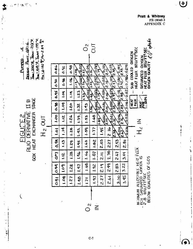
o Figure 2 shows the detailed heat f_ux and oxygenquality information for the second stage of theGOX heat exchanger at pumped idle.
,. o Figure 3 shows the Stage 1 geometry of the GOX
(,,. heat exchanger with its performance characteristics.
1985010710-118
Pratt & Whitney_" FR-18046-3
APPENDIX C
: i,7..qenderson - 2 - August 27, 1983
: i
O Figure 4 shows the Stage 2 geometry of the GOXf; heat exchanger with its performance character_qtics.
•i o Figure 5 sho_s the Stage 3 geometry with performance
J _ character Istlcs.
o Figures 6 and 7 show the pumped Idle performance ofthe reversed hydrogen flow GOX heat exchanger.
o Figures 8 and 9 show the pumped Idle performance ofthe alternate GOX heat exchanger configuration.
o Figures i0 and Ii show the tank head Idle performancefor two alternate GOX heat exchanger configurationswith two Stage 3 geometry heat exchangers.
CONCLUSIONS AND RECOMMENDATIONS:
1. The modified RL10 Derivative II_ GOX heat exchangerwill satisfy the design requirements at pumpedidle.
2. The second stage of the COX heat exchanger issensitive to hydrogen inlet temperature. Theconductivity of the Stage 2 insulation shouldbe able to be modified during testing for ahydrogen inlet temperature that is dlffeL'entthan prediction,
3. Stages 1 and 2 insulation can be varied duringtesting by changing the pressure of the gasin contact with the Insulatlon.
4. The sensitivity of the COX heat exchanger tohydrogen inlet temperature can be reduced byreversing the hydrogen flow direction. TheStage 2 insulation conductivity must bereduced to 0.033 BTU/ft,hre°R.
5. Heat leakage from the hydrogen plates to the oxygenplates through the headers can cause problems instages 1 and 2. A 0.010 inch minimum separationmust be provided between the axial flow plates andthe_eaders.
6. If fabrication problems make it impossible to makestages i and 2, a alternate configuration which usestwo stage 3 geometry heat exchangers can be used.This configuration can not be adjusted during testingif actual inlet condition are not the same as predicted.
C-2
1985010710-119
'_t_ _ _-'_'?- "_ ...... • 4
_ Pratt & Whitney' FR-18046-3
• ! APPENDIX C*
J. Henderson - 3 - Auoust 27, 1983
DI8CUSSION z e
The changes to the GOX heat e_changer due to fabricationproblems that affected the heat transfer model are as fol-lows:
1. Change Stages 1 and 2 flow path covc rplates from0.010 inches to 0.02 inches.
2. Reduced Stage 2 Insulation thickness from 0.025lnohes to 0.020 inches.
_ These modifications to the COX heat exchanger are needed tomake sure hydrogen doesn't leak through the brazed aluminum.
Several changes have been made to the COX heat exchanger to":+ correct heat transfer problems. Conduction of heat from the:_! hydrogen plates to the oxygen plates through the headers
will cause oxygen boiling, instability in Stages 1 and 2. Tocorrect this probelm an 0.010 i_ch minimum separation willbe provided between the axial flowpath plate edges and theheaders. Two hydrogen paasdges on each side of the externalplates will also be plugged since these plates must bebrazed to the oxygen headers.
The Stage 3 B/P geometry.has a higher heat transfer con-vection area than called for in the original analysis. Thehydrogen and oxygen passage hydraulic diameters are alsosmaller than what was used in the original analysis. The Jpassage hydraulic diameter is set by what can be made duringthe fabrication of the plates. These differences i; the _Stage 3 geometry cause nora heat to be transferred from thehydrogene lowering the hydrogen temperature to Stages 1 and ,:2 at pumped idle. To correct this heat transfer problem,the total heat transfer area of Stage 3 must be r_:duced.The number of hydrogen passages per plate in Stage 3 must bereduced from 52 to 47. The number of oxygen passages perplate must be reduced from 42 to 37. The conductivity ofthe Stage 2 insulation must be increased from 0.294BTU/ft.hr.eR to 0.36 BTU/ftohr,eR because o£ the lower Stage2 inlet hydrogen ten, stature at pump(d idle.
Figures 1 through 5 shoe the performance of the COX heatexchanger with modified geometry. The modified G0X heat
? . exchanger will operate without boiling instability at pumpedidle. The exit oxygen quality o_ Stage 2 at pumped idle is0.071. Stage 2 has a maximum heat flux at saturated condi-tions below qualities of 0.05 and 2.67 BTU/ft l. sac. Themaximum al_.owed heat flux is 2.8 5TU/ft ;_, sec at pump_Idle. The performance of the modified GOX heat exchanger attank head Idle and full thrust has not changed much from theoriginal analysis.
r
• c-3
]9850]07]0-]20
,_ Pratt & WhitneyFR-18046-3APPENDIX C
J. Henderson - 4 - August'27, 1983 ....
The boiling stability of Stage 1 at tank head idle and Stage
2 at idle will be sensitive to insulation conductivity andhydrogen inlet temperature. Stage 1 has the sane tolerances *to _nsulation conduct;vity and hydrogen inlet teIperaturesas stated in the orig,nal meno. Stage 2 has an insulationtolerance at pumped idle of from 0.28 BTU/ft.hr.sec to 0.4aTU/ft.hr.OR with a hydrogen inlet temperature of 300°R.The stage 2 hydrogen inlet temperature tolerance at pumpedIdle is +5 °R/-10"R with an insulation conductivity of 0.36 iBTU/ft. hr-OR. The hydrogen inlet temperature tolerance canbe exceeded if insulation conductivity is modified to offsetthe hydrogen temperatures. The conductivity of the Insu- ilatlon can be varied during testing by changing the gas incontact with the insulation or by changing the pressure of Ithe gas. Nitrogen, helium, and hydrogen can b._ used withthe insulation. The RL10 engine can tolerate _ boilinginstability pressure oscillation of +/-25t. _he hydrogeninlet temperature tolerances on Stage 1 stability could beincreased to +40 o R/-10OR without exceedlng tk.... ,r_.__s...---,_e
:_ oscillation limits.
Some alternative GOX heat exchanger configurations thatwould reduce the. sensitivities of Stage 2 to hydrogen Inlettemperature and heat flux were examined. Reversing thehydro_j_n flow direction through the GOX heat exhanger will_uce the Stage 2 sensitivities. Figures 6 and 7 show theumped Idle performance of the reversed hy6rogen flow COXeat exchanger. The conduqtlvlty of Stage 2 must be _educed
to 0.033 BTU/ft,hr,OR. The Stage 2 exit quality and maximumheat flux is 0.12 and 2.3 BTU/ft_.sec Stage 2 will have apuspe_ Idle tolerance to hydrogen inlet temperature of fron589 R to 689 R. The insulation conductivity can vary from0.028 _TU/ft-hr. • R to 0.038 BTU/ft.hr- • R without causingproblems. Increasing hydrogen flow to the RLI0 DerivativeIIB GOX heat exchanger will also reduce the Stage 2 sensi-tivity at pumped Idle. To increase hydrogen flow at pumpedIdle and O/F - 6.0 would require an oxygen injector with a1.0 in2 area, which will not be used during the low thrust_estlng.
A GOX heat exchanger configuration that uses two Stage 3eometry heat exchange_s has also been analyzed. The flrrteat exchanger is s_lit into two stages. Stage 1 uses 26 of
the 37 oxygen passages in the plate. Stage 2 uses 11 of the37 passages. The oxygen flow areas of Stages 1 and 2 are3.286 Ina and 1.39 in _ , respectively. This GOX heatexchanger configuration requires that a portion of the
, available hydrogen be taken from the 9ump to cool the hydro- Igen to Stage 2. During tank head Idle, part of the hydrogen
i will need to be bypassed around the GOX heat exchanger.Thi_ conftguratlon doesn't require insulation in Sta:_s I Iand 2.
' !t
C-4
1985010710-121
Pratt & Whitney, FR-18046-3
' APPENDIX C
3_ .,_nde_'8on - 5 - August 27, 19_3
._i_ures 8 and 9 show pumped i_0" :.erfo.rmance for the alter-', na-e GOX heat exchanger c_.._" ._" .-_on . The alternate con-
' _gutation will work at _:3_,,::,:'..L_e if a hydrogen muss flowo_ _015 lb_/sec, c_me,_ _ - _ ,e pumps to cool the Stage 2hydzo_e_ _nl_t temp:_at_c(: : 275°R. No hydrogen bypassfl_ is _equi_ed at pr_r;,T, ', ale. The Stage 2 oxygen exit
_ quality and maxirau_ hen _. _u; is 0.068 and 5.4 B_/ftZ. sac.The allowsble is 5.7 B':u/Et_-sec. Figures 10 and 11 showthe tank head idle pe_fo_p, ance of two alternate GOX heatexchanger configuration_ _bich use two Stage 3 ge_aetry heatexchangers. The halt exchanger shown on figure 11 b_asaeehydrogen around tn._ entir,., GOX heat exchanger. The hydrogenbypass flow is 0.043 1bin�set; The hydrogen flow from thepump is 0.0265 lbm/sec. Stage I has an qxygen exit qualityand maximum heat flux of 0.093 and 0.46 STO/ftlt.sec, respec-
t" tive17. The allowable heat flux is 0.50 BTO/ft .set. The
._'- configuration on Figure 12 bypasses 0.065 lbi/sec, of hydro- _gin around Stages 1 and 2. The Stage 1 exit quality and
- maximum heat flux is 0.089 and 0.46 B'ro/ft2.sec. The allot-able heat flux is 0.5 B_0/ft _ .set.
Tables 1 and 2 of the appendix show the GOX heat exchanger,- petfomance comparison between the original and new heat
exchanger decks with B/_P geometry. The original GOX heatexchanger model ' has been modified with B/P heat exchanger a_eometries which are different from what was used in the _,
original analysis. The hydrogen exit temperatures calcu- "|lat_ in the original computer model are" now based on t
enthalpy instead of specific heat. The two analytical tech-niques for oalculating heat exchanger performance agree