Page 1
l i a b l eh k C o m p u t i n gL a b o r a t o r y
Trace-Based Post-Silicon Validation Trace-Based Post-Silicon Validation for VLSI Circuitsfor VLSI Circuits
Xiao Liu Xiao Liu Department of Computer Science and Engineering
The Chinese University of Hong Kong
Page 2
Silicon Silicon Debug: Bottleneck in Prototype-tDebug: Bottleneck in Prototype-to-Volume Timeo-Volume Time
Pre-silicon verification cannot ensure the design correctness Smaller design margins – increasing chance of performance failures Un-modeled defects – higher tester escapes Higher design complexity – more time and vectors to validate
Acknowledgment: Yu-Chin Hsu, Furshing (Kevin) Tsai, Wells Jong, Ying-Tsai Chang, Novas
Test/DebugTest/DebugDesignDesign
SiliconPrototype
Concept Volume
7 to 8 monthsDecreasing
6 to 7 monthsIncreasing!
Data Quest (2002, 2004) reportData Quest (2002, 2004) report
Page 3
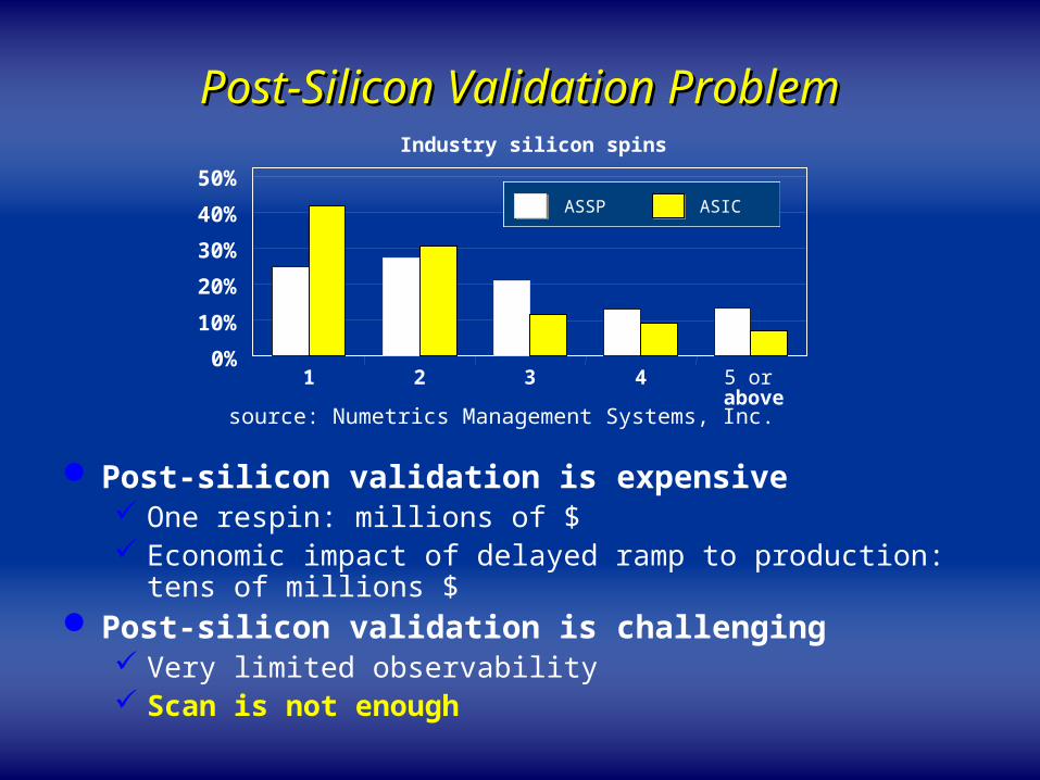
Post-Silicon Validation ProblemPost-Silicon Validation Problem
Post-silicon validation is expensive One respin: millions of $ Economic impact of delayed ramp to production: tens of millions $
Post-silicon validation is challenging Very limited observability Scan is not enough
Industry silicon spins
1 2 3 4 5 or above
0%
10%
20%
30%
40%
50%ASSP ASIC
source: Numetrics Management Systems, Inc.
Page 4
Trace-Based Post-Silicon ValidationTrace-Based Post-Silicon Validation
Pro Observe the system’s behavior in real-time Exercise functionality and timing not verified pre-silicon Detect problem difficult to reproduce on tester
Con Low coverage Hardware overhead
Debug Configuration
Data Analysis, Diagnosis
Design-for-Debug Insertion
Data dump
Acknowledgment: Yu-Chin Hsu, Furshing (Kevin) Tsai, Wells Jong, Ying-Tsai Chang, Novas
How to conduct signal tracing effectively with low-cost hardware?
Page 5
Trace-Based Post-Silicon Validation Trace-Based Post-Silicon Validation InfrastructureInfrastructure
CircuitUnder Debug
TriggerUnit
TraceBuffer
Condition Signals
Trace Signals
DfD Structure
Configuration Channel
JTAGInterface
TracePort
InterconnectionFabric
Debug Controller
[DATE-09, ATS-10,
DATE-11]
[ATS-08, DAC-09]
Page 6
Tracing Solutions for Debugging Design Tracing Solutions for Debugging Design ErrorError
Design errors violate the pre-defined specification
Signal selection for visibility enhancement [DATE-09] Challenge: Logic values are not known during signal selection Solution:
C D
E
A
B
Traced signal
0 1 2 3 4
A X X X X X
B X X X X X
C 0 1 1 0 X
D X X X X X
E X X X X X
0 1 2 3 4
A 1 1 X X X
B 0 0 X X X
C 0 1 1 0 X
D X 1 0 0 1
E X 1 0 X X
Visibility estimation metric Trace signal selectionGuide
Our solution achieves higher visibility
Page 7
Tracing Solutions for Debugging Design Tracing Solutions for Debugging Design ErrorError
Design errors violate the pre-defined specification
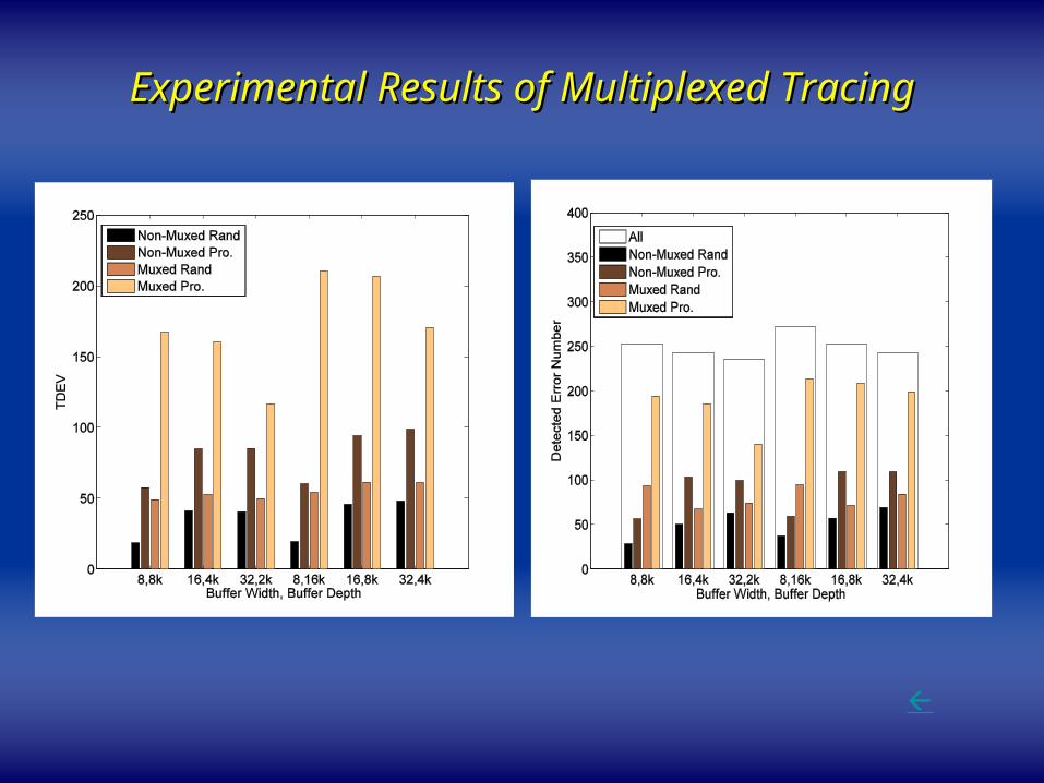
Multiplexed tracing [DATE-11]
.
.
.
FF
Combinational Logic
Error
.
.
.
FF
Combinational Logic
FF
.
.
.
Output
Combinational Logic
Trigger point Trace buffer size
Current solution: “static” tracing
Time
Trigger point Trace buffer size
Time
Proposed solution: “multiplexed” tracing
Trace those FFs with propagated evidences facilitates to detect this error
Our solution provides higher design error detection capability
Page 8
Tracing Solution for Debugging Electrical Tracing Solution for Debugging Electrical ErrorError
Electrical errors lead to reduced frequency of the circuits Sensitive to electrical environment
Coupling noise, Power supply noise, Driving strength, …
Extremely difficult to eliminate during pre-silicon verification and manufacturing test
Challenge: Difficult to localize in post-silicon validation
Solution: in-situ tracing Selectively trace signals that monitors potential errors on speedpaths
Our solution can detect errorAt its root-cause siteOn error occurrence cycleWithout “golden vectors”
Page 9
Low-Cost Trace Data Transfer Fabric Low-Cost Trace Data Transfer Fabric DesignDesign
Challenge: High flexibility v.s. Low cost Solution: Interconnection fabric design [DAC-09]
Signal classification Design optimization
Challenge: High Bandwidth v.s. Low cost Solution: Reusing test access mechanism [ATS-08]
Challenge: Systematical tracing v.s. Low cost Solution: Flexible interconnection fabric design
CUD
MUXTree
MUXTree
Non-blocking
Concentration
Network
Multiplexor Network
Trace Buffer/ Trace Port
SynchronizationLayor
Trace Clock
Non-correlated signals Correlated signals
Our solution minimizes hardware cost
Our solution reduces routing cost
Our solution enables systematical tracing
Page 10
Thank you for your attention !Thank you for your attention !
Page 11
Backup SlidesBackup Slides
Trace signal selection for visibility enhancement Multiplexed tracing for detecting design error Interconnection fabric design Signal tracing for debugging electrical error
Page 12
Experimental Results of Signal Selection for Experimental Results of Signal Selection for Visibility EnhancementVisibility Enhancement
Page 13
Experimental Results of Multiplexed Experimental Results of Multiplexed TracingTracing
Page 14
DfD Cost Comparison of DfD Cost Comparison of s38417s38417
Page 15
Speedpath-Related Electrical ErrorsSpeedpath-Related Electrical Errors ModelModel
Trace those FFs that make the above node values visible facilitates to detect this error
.
.
.
Combinational Logic
FF FF
.
.
.
a
cb
…
Required visible node values: a_in2(0), b_in1(0), c_out(0)
0
0X
a_in2(0)
00b_in1(0)
0X
c_out(0)
01 Error
Page 16
Detection Quality Evaluation: Signal Detection Quality Evaluation: Signal Selection for Non-Zero VisibilitySelection for Non-Zero Visibility
Circuit Total Signal #
Relevant Signal #
Selected Signal #
Detected Pro. Event #
Occurred Pro. Event #
Detection Quality
Time (s)
s38584 1464 198 69 7718 9519 81.1% 45.5
s38417 1664 394 157 630 1216 51.8% 125.3
DMA 3818 1482 99 6827 7615 89.6% 150.3
usb 2085 117 59 696 696 100% 77.4
des 9341 132 95 67097 70145 95.6% 668.3


![W e l c o m e [hkspra.org]hkspra.org/product_image/110_934062.pdf · W e l c o m e M e s s a g e It is ... Professor Yi-xiao Bao (China) (Malaysia)Dr. Jessie de Bruyne ... It includes](https://static.documents.pub/doc/80x56/5b27fc907f8b9ad9638b495a/w-e-l-c-o-m-e-w-e-l-c-o-m-e-m-e-s-s-a-g-e-it-is-professor-yi-xiao-bao.jpg)


![^ o W ' l' o } l Z l D ] o Á µ l s o À } u v Ç t } Ç l } v ...](https://static.documents.pub/doc/80x56/620b63818f249216b211758a/-o-w-l-o-l-z-l-d-o-l-s-o-u-v-.jpg)


![XñîìîrXïíìî uiµ}vo ]i }] À}v cPo µ Zd ^Ì d ^Ì : ^Ì î îZ í îZ](https://static.documents.pub/doc/80x56/603950eea73b96122f03366a/xrx-uivo-i-v-cpo-zd-oe-d-oe-oe-z-z-.jpg)
![D ^ } ] o ^ À ] o v l } } W } µ } Á o l h ð l î ô l î ì í ......D ^ } ] o ^ À ] o v l } } W } µ } Á o l h ð l î ô l î ì í ó. D ^ } ] o ^ À ] o v l } } W } µ }](https://static.documents.pub/doc/80x56/5f6387d75bae1175ac762f5c/d-o-o-v-l-w-o-l-h-l-l-d-.jpg)
