31
LINEAR ENCODER MODEL: L SINGLE ENCODER LINEAL MODELO: L UNITARIA MANUAL CODE: 14460031 MANUAL VERSION: V1001

LINEAR ENCODER MODEL: L SINGLEENCODER LINEAL MODELO: L UNITARIA
MANUAL CODE: 14460031MANUAL VERSION: V1001
V1001 - "L unitaria" - Page 2/12
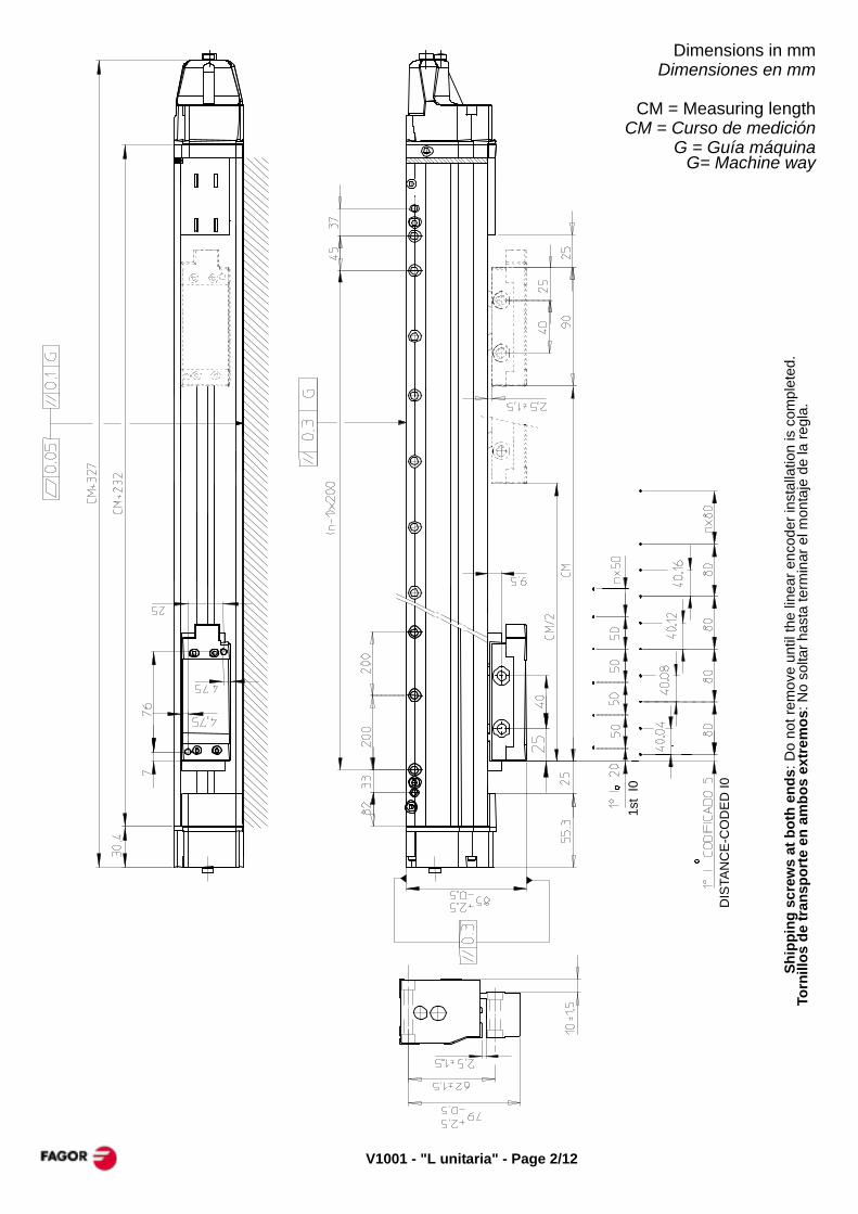
Dimensions in mmDimensiones en mm
CM = Measuring lengthCM = Curso de medición
G = Guía máquinaG= Machine way
Ship
ping
scr
ews
at b
oth
ends
: Do
not r
emov
e un
til th
e lin
ear e
ncod
er in
stal
latio
n is
com
plet
ed.
Torn
illos
de
tran
spor
te e
n am
bos
extr
emos
: No
solta
r has
ta te
rmin
ar e
l mon
taje
de
la re
gla.
DIS
TAN
CE
-CO
DE
D I0
1st
I0

Page 3/12 - "L unitaria" - V1001
MOUNTING POSSIBILITIESPOSIBILIDADES DE MONTAJE

V1001 - "L unitaria" - Page 4/12
PROCESO DE MONTAJEMOUNTING PROCESS
- 1 - - 2 -
- 3 -
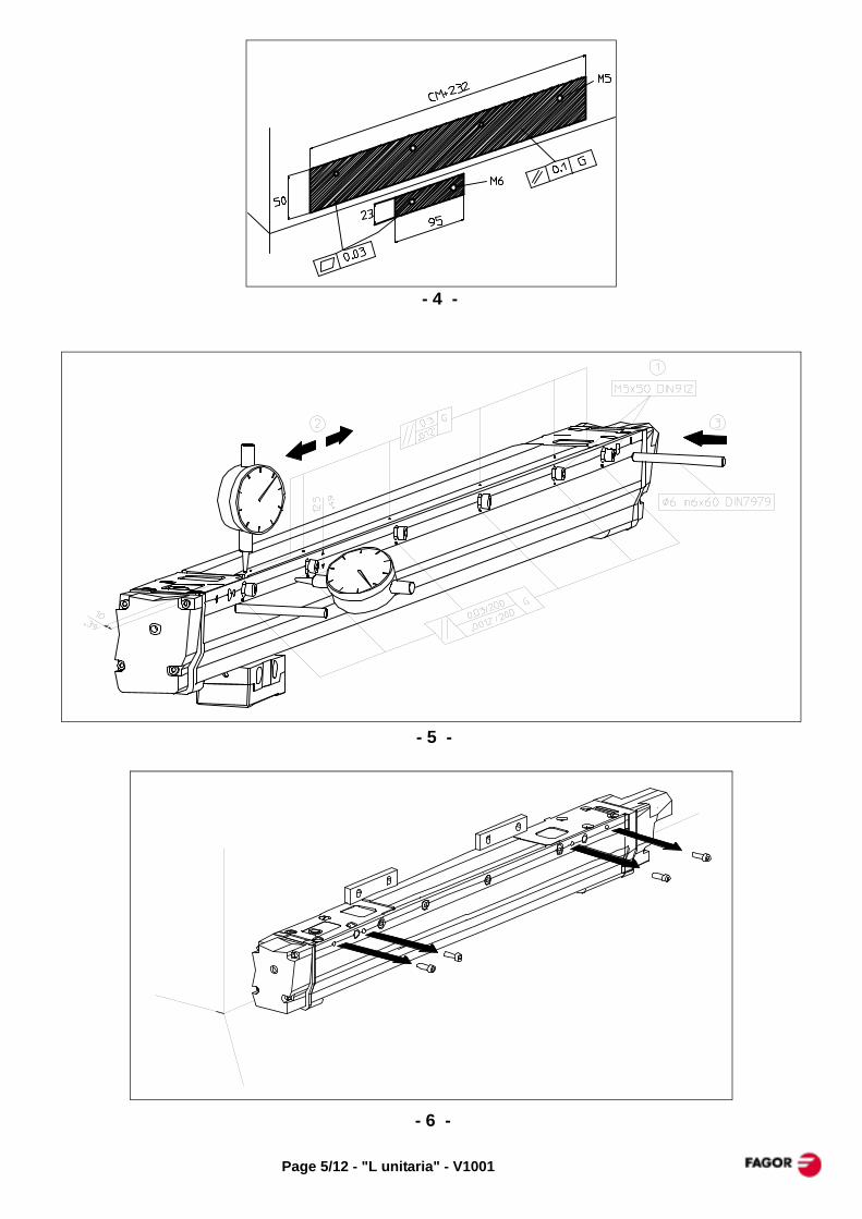
Page 5/12 - "L unitaria" - V1001
- 4 -
- 5 -
- 6 -
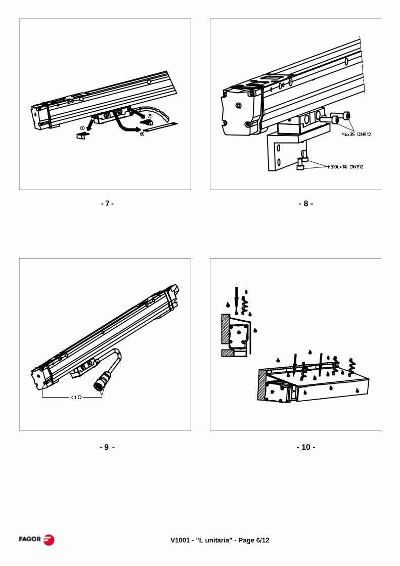
V1001 - "L unitaria" - Page 6/12
- 7 - - 8 -
- 9 - - 10 -

Page 7/12 - "L unitaria" - V1001
Option. Air intake on the endblockOpción. Entrada de aire en la regla
Option. Air intake on the reader headOpción. Entrada de aire en la cabeza
V1001 - "L unitaria" - Page 8/12
MECHANICAL CHARACTERISTICS
Maximum speed:120 m/min (4724 inch/min)
Maximum vibration: 100 m/sec² (10g)
Moving force: < 5 N
Sealing protection: IP53When using an air inlet: IP64 (DIN 40050)
Ambient temperature: 0°C .. 50°C (32°F .. 122°F)Storage temperature: -20°C ..+70°C
(-4°F.. 158°F)Weight: 1.5Kg + 4Kg/m
Scale: 40µm-pitch graduated band.
Cable Length: 1, 3, 6, 9, 12 m extendable to up to 150 m (depending on the type of signal) with optional extension cables of 5, 10, 15, 20 and 25 m.Note: When using extension cables, the cable
connected to the reader head should be the shortest possible (e.g. 1m).
Cable bending radius: > 75 mm
Reference marks:LX, LP Models
One reference mark every 50 mm (2 inches) in both directions. The first one at 20 mm from the beginning of the measuring length.
LOX, LOP ModelsSemi-absolute scales where it is possible to
know the actual absolute axis position simply by moving it a maximum of 80mm from its current position.
CARACTERISTICAS MECANICAS
Velocidad máxima: 120 m/min
Vibración máxima: 100 m/seg² (10g)
Fuerza de desplazamiento: < 5 N
Estanqueidad: IP53Si se utiliza un dispositivo de entrada de aire la estanqueidad es IP64 (DIN 40050)
Temperatura ambiente:0 ... 50°C
Temperatura almacenamiento-20° ... +70°C
Peso: 1,5Kg + 4Kg/m
Escala: Fleje de periodo 40 µm
Longitud del cable: 1, 3, 6, 9, 12 m extendible hasta un máximo de 150 m (dependiendo del tipo de señal) mediante alargaderas opcionales de 5, 10, 15, 20 y 25 m.Nota: Cuando se utilicen alargaderas, el cable
que se conecte a la cabeza lectora debe ser lo más corto posible (p.e. 1m).
Radio de curvatura del cable: > 75 mm
Referencias:Modelos LX, LP
Una marca de referencia cada 50 mm en ambos sentidos. La primera marca a 20 mm del inicio del curso de medición.
Modelos LOX, LOPSon reglas semiabsolutas que permiten
conocer la posición real de la máquina con un desplazamiento máximo de 80mm.
Page 9/12 - "L unitaria" - V1001
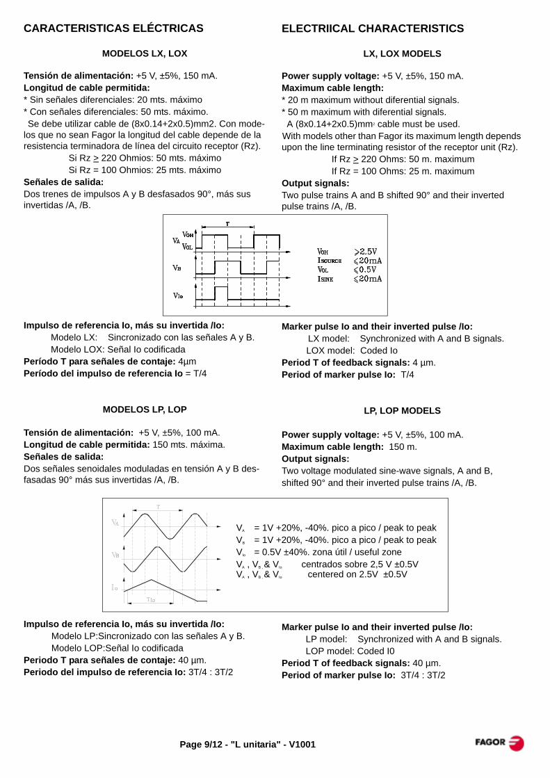
ELECTRIICAL CHARACTERISTICS
LX, LOX MODELS
Power supply voltage: +5 V, ±5%, 150 mA.Maximum cable length: * 20 m maximum without diferential signals.* 50 m maximum with diferential signals. A (8x0.14+2x0.5)mm2 cable must be used.With models other than Fagor its maximum length depends upon the line terminating resistor of the receptor unit (Rz).
If Rz > 220 Ohms: 50 m. maximumIf Rz = 100 Ohms: 25 m. maximum
Output signals:Two pulse trains A and B shifted 90° and their inverted pulse trains /A, /B.
Marker pulse Io and their inverted pulse /Io:LX model: Synchronized with A and B signals.LOX model: Coded Io
Period T of feedback signals: 4 µm.Period of marker pulse Io: T/4
LP, LOP MODELS
Power supply voltage: +5 V, ±5%, 100 mA.Maximum cable length: 150 m.Output signals:Two voltage modulated sine-wave signals, A and B,shifted 90° and their inverted pulse trains /A, /B.
Marker pulse Io and their inverted pulse /Io:LP model: Synchronized with A and B signals.LOP model: Coded I0
Period T of feedback signals: 40 µm.Period of marker pulse Io: 3T/4 : 3T/2
CARACTERISTICAS ELÉCTRICAS
MODELOS LX, LOX
Tensión de alimentación: +5 V, ±5%, 150 mA.Longitud de cable permitida: * Sin señales diferenciales: 20 mts. máximo* Con señales diferenciales: 50 mts. máximo. Se debe utilizar cable de (8x0.14+2x0.5)mm2. Con mode-los que no sean Fagor la longitud del cable depende de la resistencia terminadora de línea del circuito receptor (Rz).
Si Rz > 220 Ohmios: 50 mts. máximoSi Rz = 100 Ohmios: 25 mts. máximo
Señales de salida:Dos trenes de impulsos A y B desfasados 90°, más sus invertidas /A, /B.
Impulso de referencia Io, más su invertida /Io:Modelo LX: Sincronizado con las señales A y B.Modelo LOX: Señal Io codificada
Período T para señales de contaje: 4µmPeríodo del impulso de referencia Io = T/4
MODELOS LP, LOP
Tensión de alimentación: +5 V, ±5%, 100 mA.Longitud de cable permitida: 150 mts. máxima.Señales de salida:Dos señales senoidales moduladas en tensión A y B des-fasadas 90° más sus invertidas /A, /B.
Impulso de referencia Io, más su invertida /Io:Modelo LP:Sincronizado con las señales A y B.Modelo LOP:Señal Io codificada
Periodo T para señales de contaje: 40 µm.Periodo del impulso de referencia Io: 3T/4 : 3T/2
VA = 1V +20%, -40%. pico a pico / peak to peakVB = 1V +20%, -40%. pico a pico / peak to peakVIo = 0.5V ±40%. zona útil / useful zoneVA , VB , & VIo centrados sobre 2,5 V ±0.5VVA , VB , & VIo centered on 2.5V ±0.5V

V1001 - "L unitaria" - Page 10/12
Grating pitch : (M) = Male / Macho Paso de graduación (F) = Female / Hembra
Signal Cable Fagor Others Connector
Period x factor Señal Manguera NV VN CNC Otros Conector
EC-P-D * SUBD-15HD (M)EC-P-FT * SUBD-15 (M)
EC-AS-0-N * -EC-P-0 * -EC-P-D * SUBD-15HD (M)EC-P-FT * SUBD-15 (M)EC-P-0 * -
EC-AS-0-N * -EC-AS-H * SUBD-15 (F)
Note: The optional letter "N" indicates that it does not have the metallic protection tube. For example: EC-P-0-N or EC-P-FT-NNota: La letra opcional "N" indica que no lleva tubo metálico de protección. Por ejemplo: EC-P-0-N o EC-P-FT-N
P (1Vpp sine / seno)
40 µm
X - TTL
40µm -
4µm 10
Connected unitEquipo conectado
Fagor DRO
Cable ->Connector ->
Signal ->Señal PIN COLOR PIN COLOR PIN COLOR PIN COLOR PIN COLOR
Brown Brown Brown Brown BrownMarrón Marrón Marrón Marrón MarrónWhite White White White White
Blanco Blanco Blanco Blanco Blanco
Green Green Green Green GreenVerde Verde Verde Verde VerdeYellow Yellow Yellow Yellow Yellow
Amarillo Amarillo Amarillo Amarillo AmarilloBlue Blue Blue Blue BlueAzul Azul Azul Azul AzulRed Red Red Red RedRojo Rojo Rojo Rojo RojoGrey Grey Grey Grey GreyGris Gris Gris Gris GrisPink Pink Pink Pink PinkRosa Rosa Rosa Rosa Rosa
Ext. shield Shield Shield Housing Shield ShieldMalla ext. Malla Malla Carcasa Malla MallaInt. shieldMalla int.
Black BlackNegro NegroPurple PurpleVioleta Violeta
EC-P-0EC-AS-H EC-AS-0-N
11
9
7
-
1
2
- -
-
-
-
-
12
10
-
-
6
-
15
-
2
3
4
5
6
15
1
2
3
4
5
-
-
-
-
-
3
4
6
/Io
/Alarm
0V sensor
+5V sensor
/A
B
/B
Io
+5V
0V
-
9
11
9
11
-5V
A 1
-
--X / P X / P
SUBD-15 (M)X / P
EC-P-D EC-P-FT
-
-
PSUBD-15 (F)SUBD-15 HD (M)
X / P
CABLES / MANGUERAS
CONNECTOR a b c d e fSUB-D 15 40 42 33 33.3 27.3 10.4SUB-D 15HD 53 31 38 25 19 10.4
Dimensions in mm
f
SUB-D 15 M
SUB-D 15 F
SUB-D 15 HD (M)
e d
ca
SUB-D 15 xx
b
Page 11/12 - "L unitaria" - V1001
WARRANTY
* Term: 12 months from factory invoice date.* It covers parts and labor at FAGOR AUTOMATION.* Travel expenses are payable by the customer.* Damages due to causes external to FAGOR
AUTOMATION, such as unauthorized handling, blows, etc. are not covered.
DECLARATION OF CONFORMITY
Manufacturer:Fagor Automation, S. Coop.Barrio de San Andrés 19, 20500, Mondragón -Guipúzcoa- (SPAIN)
We declare under our exclusive responsibility the conformity of the product referred to in this manual.
Note. Some additional characters may follow the model references indicated in this manual. They all comply with the following regulations:
ELECTROMAGNETIC COMPATIBILITY:
EN 61000-6-2:2005 Standard on immunity in industrial environments
EN 61000-6-4:2007 Standard on emission in industrial environments
According to the European Directive: 2004/108/CE on electromagnetic compatibility.
Mondragón September 1st 2009
The information described in this manual may be subject to variations due to technical modifications.
FAGOR AUTOMATION, S. Coop. Ltda. reserves the right to modify the contents of this manual without prior notice.
GARANTÍA
* 12 meses desde fecha de expedición de fábrica.* Cubre gastos de Materiales y Mano de Obra de
reparación en FAGOR AUTOMATION.* Gastos de desplazamiento a cargo del cliente.* No cubre averías por causas ajenas a FAGOR
AUTOMATION, como: golpes, manipulación por personal no autorizado, etc.
DECLARACION DE CONFORMIDAD
Fabricante:Fagor Automation, S. Coop.Barrio de San Andrés 19, 20500, Mondragón -Guipúzcoa- (ESPAÑA)
Declaramos bajo nuestra exclusiva responsabilidad la conformidad del producto al que hace referencia este manual
Nota. Algunos caracteres adicionales pueden seguir a las referencias de los modelos indicados en este manual. Todos ellos cumplen con las siguientes normas:
COMPATIBILIDAD ELECTROMAGNÉTICA:
EN 61000-6-2:2005 Norma de Inmunidad en entornos industriales
EN 61000-6-4:2007 Norma de Emisión en entornos industriales
De acuerdo con las disposiciones de la Directiva Comunitaria: 2004/108/CE de Compatibilidad Electromagnética.
Mondragón a 1 de Septiembre de 2009
La información descrita en este manual puede estar sujeta a variaciones motivadas por modificaciones técnicas.FAGOR AUTOMATION S. Coop. Ltda. se reserva el derecho de modificar su contenido, no estando obligada a notificar las variaciones.

Fagor Automation S. Coop.Bº San Andrés Nº19Apdo Correos 14420500 - Arrasate/Mondragón- Spain -Web: www.fagorautomation.comEmail: [email protected].: (34) 943 719200Fax: (34) 943 791712
LINEAR ENCODER MODEL: L MODULARENCODER LINEAL MODELO: L MODULAR
MANUAL CODE: 14460032MANUAL VERSION: V1001

Page 3/20 - "L modular" - V1001
Dimensions in mmDimensiones en mm
CM = Measuring lengthCM = Curso de medición
G = Guía máquinaG= Machine way
DIS
TAN
CE
-CO
DE
D I0
1st
I0

V1001 - "L modular" - Page 4/20
Módulo "KT""KT" Module
Módulo "14""14" Module
Módulo "ET""ET" Module
Módulo "KT""KT" Module
Módulo "14""14" Module
Módulo "ET""ET" Module
4240 mm L xxx 42 1 1 14 ET 17240 mm L xxx 172 1 10 18 ET4440 mm L xxx 44 1 1 16 ET 17440 mm L xxx 174 1 10 20 ET4640 mm L xxx 46 1 1 18 ET 17640 mm L xxx 176 1 10 22 ET4840mm L xxx 48 1 1 20 ET 17840mm L xxx 178 1 11 10 ET5040mm L xxx 50 1 1 22 ET 18040mm L xxx 180 1 11 12 ET5240 mm L xxx 52 1 2 10 ET 18240 mm L xxx 182 1 11 14 ET5440 mm L xxx 54 1 2 12 ET 18440 mm L xxx 184 1 11 16 ET5640 mm L xxx 56 1 2 14 ET 18640 mm L xxx 186 1 11 18 ET5840mm L xxx 58 1 2 16 ET 18840mm L xxx 188 1 11 20 ET6040mm L xxx 60 1 2 18 ET 19040mm L xxx 190 1 11 22 ET6240 mm L xxx 62 1 2 20 ET 19240 mm L xxx 192 1 12 10 ET6440 mm L xxx 64 1 2 22 ET 19440 mm L xxx 194 1 12 12 ET6640 mm L xxx 66 1 3 10 ET 19640 mm L xxx 196 1 12 14 ET6840mm L xxx 68 1 3 12 ET 19840mm L xxx 198 1 12 16 ET7040mm L xxx 70 1 3 14 ET 20040mm L xxx 200 1 12 18 ET7240 mm L xxx 72 1 3 16 ET 20240 mm L xxx 202 1 12 20 ET7440 mm L xxx 74 1 3 18 ET 20440 mm L xxx 204 1 12 22 ET7640 mm L xxx 76 1 3 20 ET 20640 mm L xxx 206 1 13 10 ET7840mm L xxx 78 1 3 22 ET 20840mm L xxx 208 1 13 12 ET8040mm L xxx 80 1 4 10 ET 21040mm L xxx 210 1 13 14 ET8240 mm L xxx 82 1 4 12 ET 21240 mm L xxx 212 1 13 16 ET8440 mm L xxx 84 1 4 14 ET 21440 mm L xxx 214 1 13 18 ET8640 mm L xxx 86 1 4 16 ET 21640 mm L xxx 216 1 13 20 ET8840mm L xxx 88 1 4 18 ET 21840mm L xxx 218 1 13 22 ET9040mm L xxx 90 1 4 20 ET 22040mm L xxx 220 1 14 10 ET9240 mm L xxx 92 1 4 22 ET 22240 mm L xxx 222 1 14 12 ET9440 mm L xxx 94 1 5 10 ET 22440 mm L xxx 224 1 14 14 ET9640 mm L xxx 96 1 5 12 ET 22640 mm L xxx 226 1 14 16 ET9840mm L xxx 98 1 5 14 ET 22840mm L xxx 228 1 14 18 ET
10040mm L xxx 100 1 5 16 ET 23040mm L xxx 230 1 14 20 ET10240 mm L xxx 102 1 5 18 ET 23240 mm L xxx 232 1 14 22 ET10440 mm L xxx 104 1 5 20 ET 23440 mm L xxx 234 1 15 10 ET10640 mm L xxx 106 1 5 22 ET 23640 mm L xxx 236 1 15 12 ET10840mm L xxx 108 1 6 10 ET 23840 mm L xxx 238 1 15 14 ET11040mm L xxx 110 1 6 12 ET 24040mm L xxx 240 1 15 16 ET11240 mm L xxx 112 1 6 14 ET 24240 mm L xxx 242 1 15 18 ET11440 mm L xxx 114 1 6 16 ET 24440 mm L xxx 244 1 15 20 ET11640 mm L xxx 116 1 6 18 ET 24640 mm L xxx 246 1 15 22 ET11840mm L xxx 118 1 6 20 ET 24840mm L xxx 248 1 16 10 ET12040mm L xxx 120 1 6 22 ET 25040mm L xxx 250 1 16 12 ET12240 mm L xxx 122 1 7 10 ET 25240 mm L xxx 252 1 16 14 ET12440 mm L xxx 124 1 7 12 ET 25440 mm L xxx 254 1 16 16 ET12640 mm L xxx 126 1 7 14 ET 25640 mm L xxx 256 1 16 18 ET12840mm L xxx 128 1 7 16 ET 25840mm L xxx 258 1 16 20 ET13040mm L xxx 130 1 7 18 ET 26040mm L xxx 260 1 16 22 ET13240 mm L xxx 132 1 7 20 ET 26240 mm L xxx 262 1 17 10 ET13440 mm L xxx 134 1 7 22 ET 26440 mm L xxx 264 1 17 12 ET13640 mm L xxx 136 1 8 10 ET 26640 mm L xxx 266 1 17 14 ET13840mm L xxx 138 1 8 12 ET 26840mm L xxx 268 1 17 16 ET14040mm L xxx 140 1 8 14 ET 27040mm L xxx 270 1 17 18 ET14240 mm L xxx 142 1 8 16 ET 27240 mm L xxx 272 1 17 20 ET14440 mm L xxx 144 1 8 18 ET 27440mm L xxx 274 1 17 22 ET14640 mm L xxx 146 1 8 20 ET 27640 mm L xxx 276 1 18 10 ET14840mm L xxx 148 1 8 22 ET 27840mm L xxx 278 1 18 12 ET15040mm L xxx 150 1 9 10 ET 28040mm L xxx 280 1 18 14 ET15240 mm L xxx 152 1 9 12 ET 28240 mm L xxx 282 1 18 16 ET15440 mm L xxx 154 1 9 14 ET 28440 mm L xxx 284 1 18 18 ET15640 mm L xxx 156 1 9 16 ET 28640 mm L xxx 286 1 18 20 ET15840mm L xxx 158 1 9 18 ET 28840mm L xxx 288 1 18 22 ET16040mm L xxx 160 1 9 20 ET 29040mm L xxx 290 1 19 10 ET16240 mm L xxx 162 1 9 22 ET 29240 mm L xxx 292 1 19 12 ET16440 mm L xxx 164 1 10 10 ET 29440 mm L xxx 294 1 19 14 ET16640 mm L xxx 166 1 10 12 ET 29640 mm L xxx 296 1 19 16 ET16840mm L xxx 168 1 10 14 ET 29840mm L xxx 298 1 19 18 ET17040mm L xxx 170 1 10 16 ET 30040mm L xxx 300 1 19 20 ET
COMPOSICION / COMPOSITIONCurso de medición
Measuring length
COMPOSICION / COMPOSITIONCurso de medición
Measuring length
Model Model

Page 5/20 - "L modular" - V1001
En el caso de que la superficie donde se vaya a mon-tar la regla no reúna las condiciones de la figura de abajo, se debe realizar un PREMONTAJE siguiendo el procedimiento indicado en estas páginas.
When the linear encoder is to be mounted on a sur-face that does not meet the conditions shown in the drawing below, a PRE-INSTSALLATION is required following the steps described here.
PREMONTAJE / PREINSTALLATION
A
Fijación de los apoyos laterales en superficies con paralelismo0,1 mm y sin apoyo superior. Utilizar las calas de montaje RF2.
Securing the side brackets onto surfaces parallel within 0.1 mm (0.004 inch) and without top sup-port.Use mounting bracket RF2.
Fijación de la base de apoyos laterales cuando la superficie dispone de un paralelismo mayor de 0,1 mm. Utilizar las calas de montaje RF1 y RF2.
Securing the base plates for the side brackets when the available surface is not parallel within 0.1 mm (0.004 inch). Use mounting bracket RF1 and RF2.
V1001 - "L modular" - Page 6/20
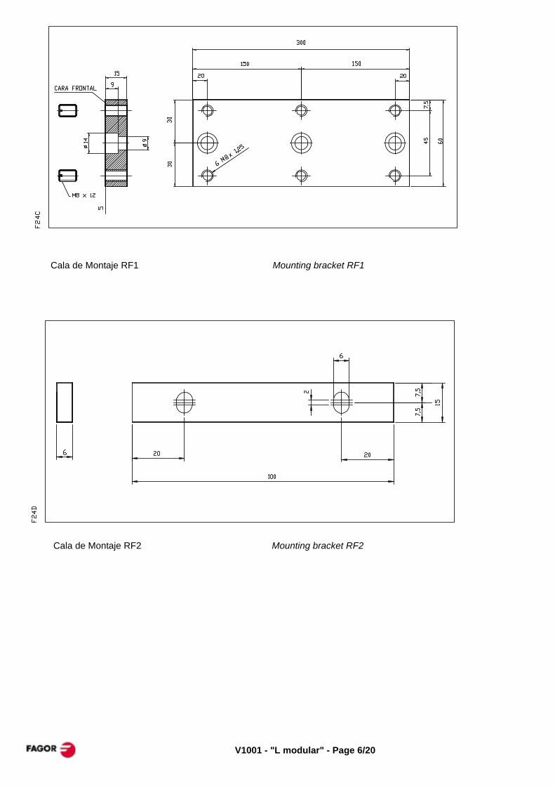
Cala de Montaje RF1 Mounting bracket RF1
Cala de Montaje RF2 Mounting bracket RF2
Page 7/20 - "L modular" - V1001
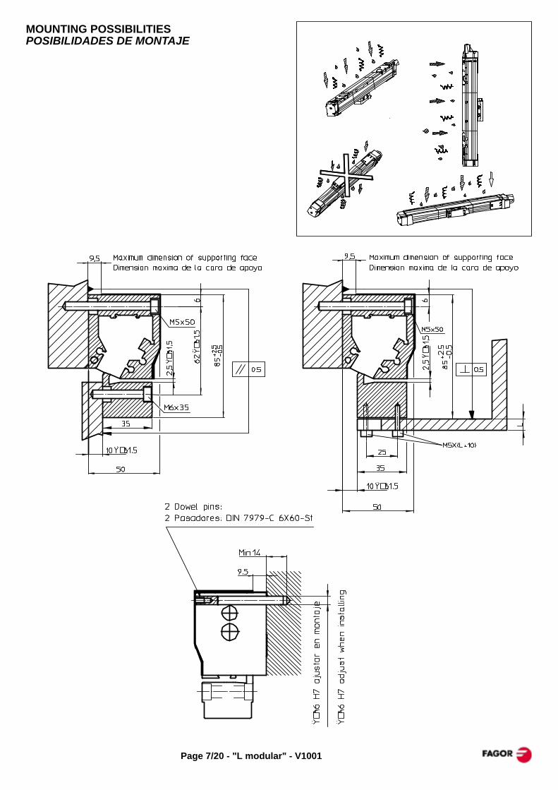
MOUNTING POSSIBILITIESPOSIBILIDADES DE MONTAJE
V1001 - "L modular" - Page 8/20
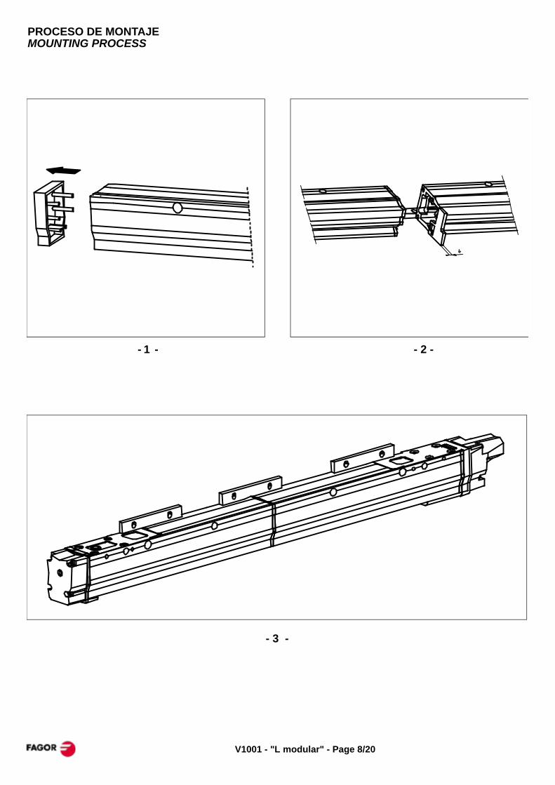
PROCESO DE MONTAJEMOUNTING PROCESS
- 1 - - 2 -
- 3 -

Page 9/20 - "L modular" - V1001
- 4 -
- 5 -

V1001 - "L modular" - Page 10/20
- 7 - - 8 -
- 6 -
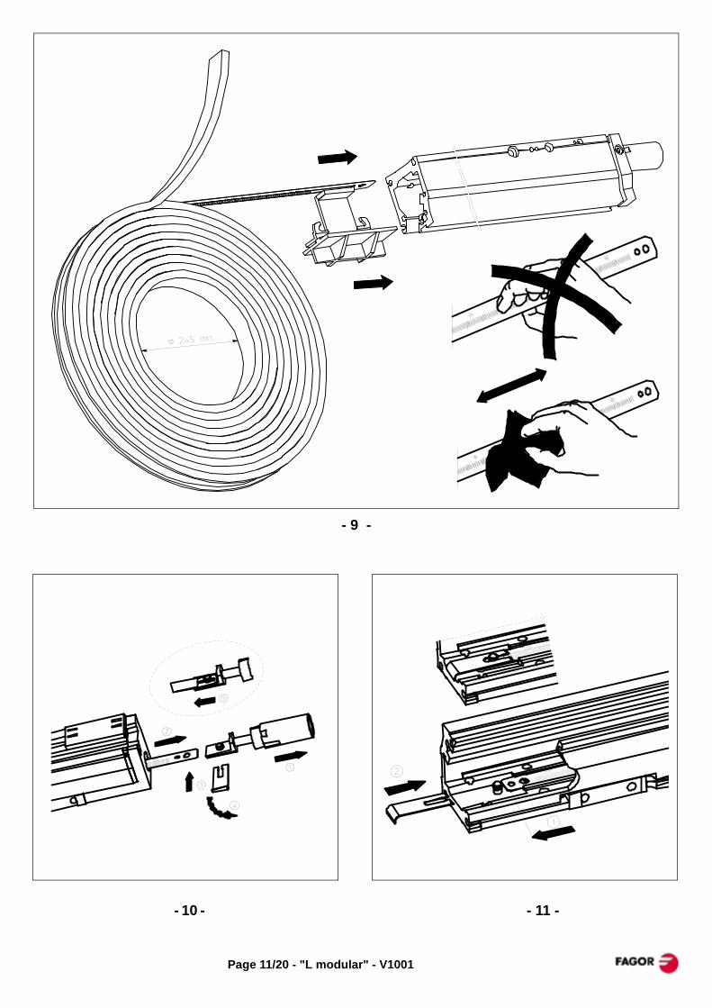
Page 11/20 - "L modular" - V1001
- 10 - - 11 -
- 9 -
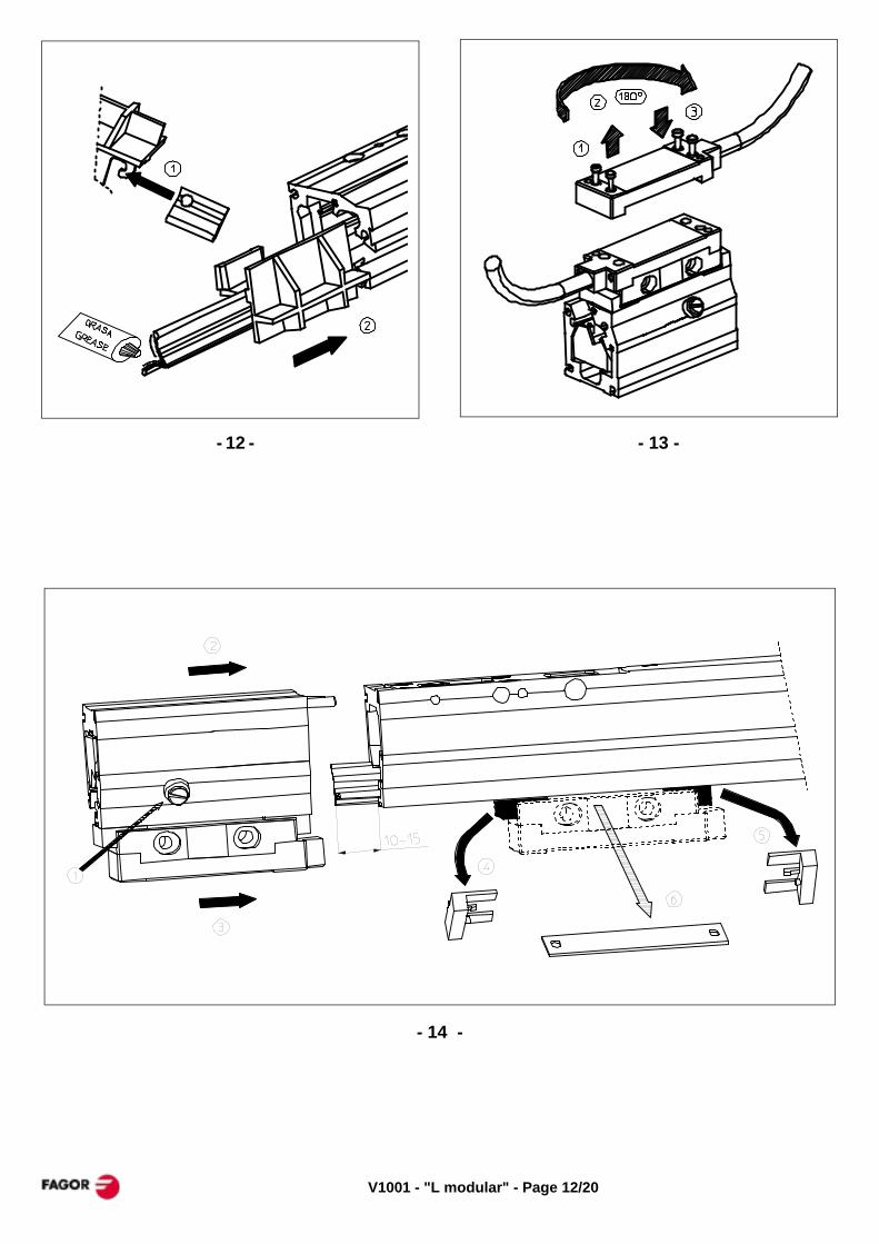
V1001 - "L modular" - Page 12/20
- 12 - - 13 -
- 14 -
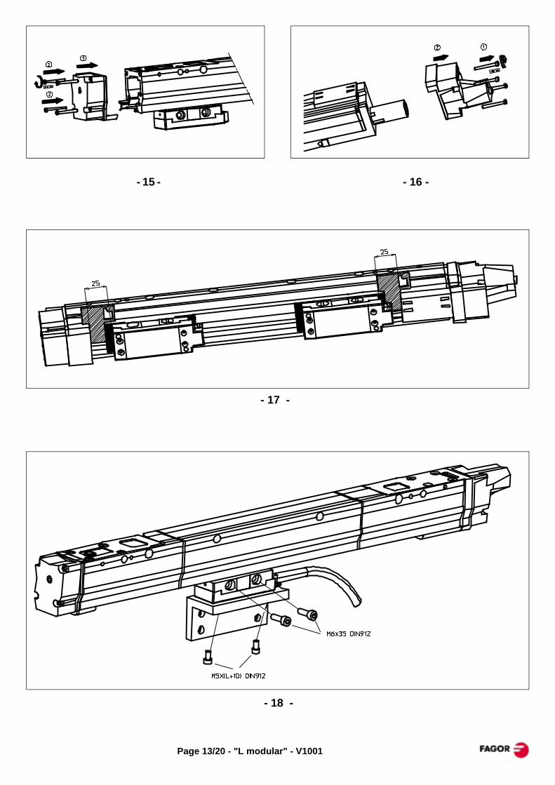
Page 13/20 - "L modular" - V1001
- 15 - - 16 -
- 17 -
- 18 -
V1001 - "L modular" - Page 14/20
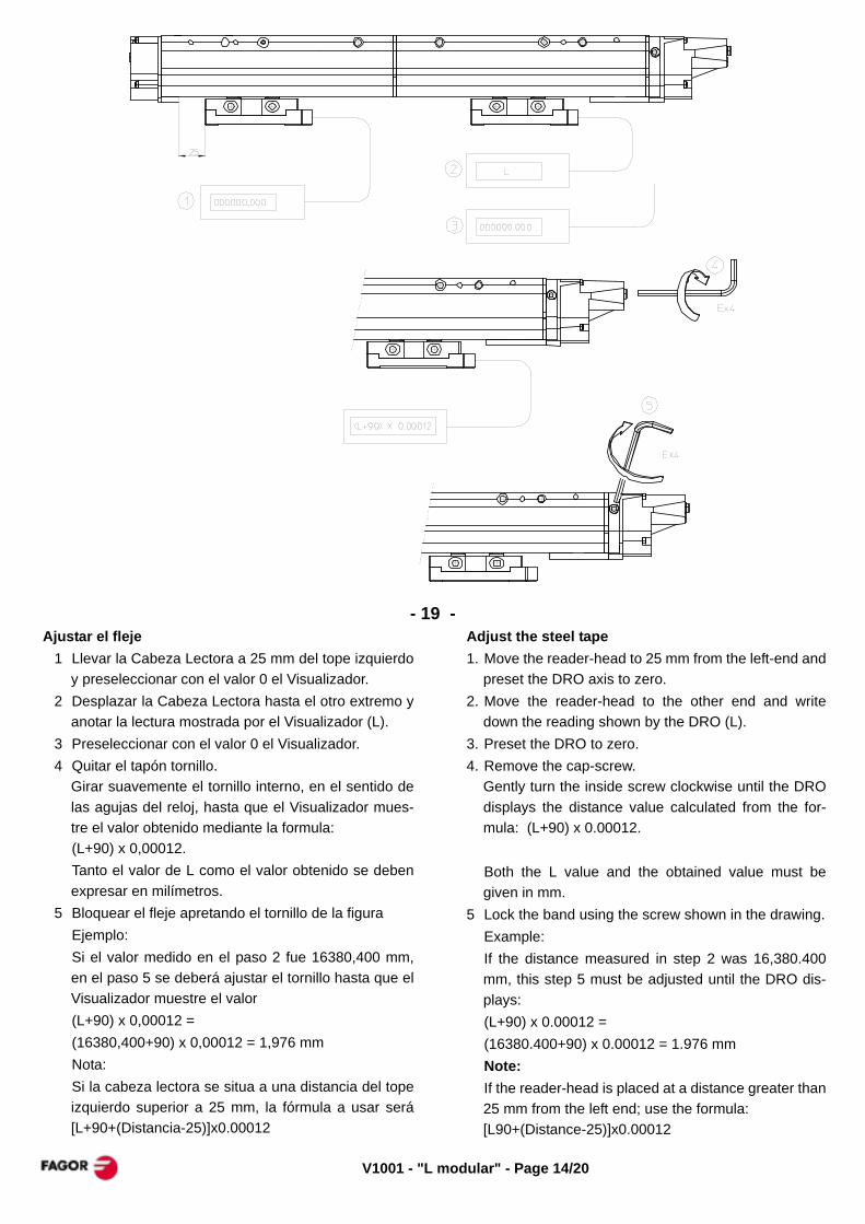
- 19 - Ajustar el fleje
1 Llevar la Cabeza Lectora a 25 mm del tope izquierdoy preseleccionar con el valor 0 el Visualizador.
2 Desplazar la Cabeza Lectora hasta el otro extremo yanotar la lectura mostrada por el Visualizador (L).
3 Preseleccionar con el valor 0 el Visualizador.4 Quitar el tapón tornillo.
Girar suavemente el tornillo interno, en el sentido delas agujas del reloj, hasta que el Visualizador mues-tre el valor obtenido mediante la formula: (L+90) x 0,00012.Tanto el valor de L como el valor obtenido se debenexpresar en milímetros.
5 Bloquear el fleje apretando el tornillo de la figuraEjemplo: Si el valor medido en el paso 2 fue 16380,400 mm,en el paso 5 se deberá ajustar el tornillo hasta que elVisualizador muestre el valor(L+90) x 0,00012 = (16380,400+90) x 0,00012 = 1,976 mmNota:Si la cabeza lectora se situa a una distancia del topeizquierdo superior a 25 mm, la fórmula a usar será[L+90+(Distancia-25)]x0.00012
Adjust the steel tape1. Move the reader-head to 25 mm from the left-end and
preset the DRO axis to zero.2. Move the reader-head to the other end and write
down the reading shown by the DRO (L).3. Preset the DRO to zero.4. Remove the cap-screw.
Gently turn the inside screw clockwise until the DROdisplays the distance value calculated from the for-mula: (L+90) x 0.00012.
Both the L value and the obtained value must begiven in mm.
5 Lock the band using the screw shown in the drawing.Example:If the distance measured in step 2 was 16,380.400mm, this step 5 must be adjusted until the DRO dis-plays:(L+90) x 0.00012 = (16380.400+90) x 0.00012 = 1.976 mmNote:If the reader-head is placed at a distance greater than25 mm from the left end; use the formula: [L90+(Distance-25)]x0.00012

Page 15/20 - "L modular" - V1001
- 20 - - 21 -
Option. Air intake on the endblockOpción. Entrada de aire en la regla
V1001 - "L modular" - Page 16/20
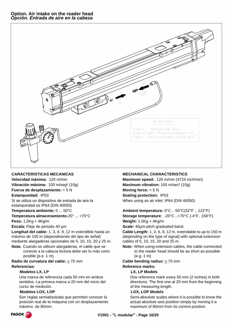
Option. Air intake on the reader headOpción. Entrada de aire en la cabeza
CARACTERISTICAS MECANICASVelocidad máxima: 120 m/minVibración máxima: 100 m/seg² (10g)Fuerza de desplazamiento: < 5 NEstanqueidad: IP53Si se utiliza un dispositivo de entrada de aire la estanqueidad es IP64 (DIN 40050)Temperatura ambiente: 0 ... 50°CTemperatura almacenamiento-20° ... +70°CPeso: 1,5Kg + 4Kg/mEscala: Fleje de periodo 40 µmLongitud del cable: 1, 3, 6, 9, 12 m extendible hasta un máximo de 150 m (dependinendo del tipo de señal) mediante alargaderas opcionales de 5, 10, 15, 20 y 25 m.Nota: Cuando se utilicen alargaderas, el cable que se
conecte a la cabeza lectora debe ser lo más corto posible (p.e. 1 m).
Radio de curvatura del cable: > 75 mmReferencias:
Modelos LX, LPUna marca de referencia cada 50 mm en ambos sentidos. La primera marca a 20 mm del inicio del curso de medición.Modelos LOX, LOPSon reglas semiabsolutas que permiten conocer la posición real de la máquina con un desplazamiento máximo de 80mm.
MECHANICAL CHARACTERISTICSMaximum speed: 120 m/min (4724 inch/min)Maximum vibration: 100 m/sec² (10g)Moving force: < 5 NSealing protection: IP53When using an air inlet: IP64 (DIN 40050)
Ambient temperature: 0°C .. 50°C(32°F .. 122°F)Storage temperature: -20°C ..+70°C (-4°F.. 158°F)Weight: 1.5Kg + 4Kg/mScale: 40µm-pitch graduated band.Cable Length: 1, 3, 6, 9, 12 m. extendable to up to 150 m (depending on the type of signal) with optional extension cables of 5, 10, 15, 20 and 25 m.Note: When using extension cables, the cable connected
to the reader head should be as short as possible (e.g. 1 m)
Cable bending radius: > 75 mmReference marks:
LX, LP ModelsOne reference mark every 50 mm (2 inches) in both directions. The first one at 20 mm from the beginning of the measuring length.LOX, LOP ModelsSemi-absolute scales where it is possible to know the actual absolute axis position simply by moving it a maximum of 80mm from its current position.

Page 17/20 - "L modular" - V1001
ELECTRICAL CHARACTERISTICS
LX, LOX MODELS
Power supply voltage: +5 V, ±5%, 150 mA.Maximum cable length: * 20 m maximum without diferential signals.* 50 m maximum with diferential signals. A (8x0.14+2x0.5)mm2 cable must be used.With models other than Fagor its maximum length depends upon the line terminating resistor of the receptor unit (Rz).
If Rz > 220 Ohms: 50 m. maximumIf Rz = 100 Ohms: 25 m. maximum
Output signals:Two pulse trains A and B shifted 90° and their inverted
pulse trains /A, /B.
Marker pulse Io and their inverted pulse /Io:LX model: Synchronized with A and B signals.LOX model: Coded Io
Period T of feedback signals: 4 µm.Period of marker pulse Io: T/4
LP, LOP MODELS
Power supply voltage: +5 V, ±5%, 100 mA.Maximum cable length: 150 m.Output signals:Two voltage modulated sine-wave signals, A and B,shifted 90° and their inverted pulse trains /A, /B.
Marker pulse Io and their inverted pulse /Io:LP model: Synchronized with A and B signals.LOP model: Coded I0
Period T of feedback signals: 40 µm.Period of marker pulse Io: 3T/4 : 3T/2
CARACTERISTICAS ELÉCTRICAS
MODELOS LX, LOX
Tensión de alimentación: +5 V, ±5%, 150 mA.Longitud de cable permitida: * Sin señales diferenciales: 20 mts. máximo* Con señales diferenciales: 50 mts. máximo. Se debe utilizar cable de (8x0.14+2x0.5)mm2. Con mode-los que no sean Fagor la longitud del cable depende de la resistencia terminadora de línea del circuito receptor (Rz).
Si Rz > 220 Ohmios: 50 mts. máximoSi Rz = 100 Ohmios: 25 mts. máximo
Señales de salida:Dos trenes de impulsos A y B desfasados 90°, más sus invertidas /A, /B.
Impulso de referencia Io, más su invertida /Io:Modelo LX: Sincronizado con las señales A y B.Modelo LOX: Señal Io codificada
Período T para señales de contaje: 4µmPeríodo del impulso de referencia Io = T/4
MODELOS LP, LOP
Tensión de alimentación: +5 V, ±5%, 100 mA.Longitud de cable permitida: 150 mts. máxima.Señales de salida:Dos señales senoidales moduladas en tensión A y B des-fasadas 90° más sus invertidas /A, /B.
Impulso de referencia Io, más su invertida /Io:Modelo LP:Sincronizado con las señales A y B.Modelo LOP:Señal Io codificada
Periodo T para señales de contaje: 40 µm.Periodo del impulso de referencia Io: 3T/4 : 3T/2
VA = 1V +20%, -40%. pico a pico / peak to peakVB = 1V +20%, -40%. pico a pico / peak to peakVIo = 0.5V ±40%. zona útil / useful zoneVA , VB , & VIo centrados sobre 2,5 V ±0.5VVA , VB , & VIo centered on 2.5V ±0.5V

V1001 - "L modular" - Page 18/20
Grating pitch : (M) = Male / Macho Paso de graduación (F) = Female / Hembra
Signal Cable Fagor Others Connector
Period x factor Señal Manguera NV VN CNC Otros Conector
EC-P-D * SUBD-15HD (M)EC-P-FT * SUBD-15 (M)
EC-AS-0-N * -EC-P-0 * -EC-P-D * SUBD-15HD (M)EC-P-FT * SUBD-15 (M)EC-P-0 * -
EC-AS-0-N * -EC-AS-H * SUBD-15 (F)
Note: The optional letter "N" indicates that it does not have the metallic protection tube. For example: EC-P-0-N or EC-P-FT-NNota: La letra opcional "N" indica que no lleva tubo metálico de protección. Por ejemplo: EC-P-0-N o EC-P-FT-N
P (1Vpp sine / seno)
40 µm
X - TTL
40µm -
4µm 10
Connected unitEquipo conectado
Fagor DRO
Cable ->Connector ->
Signal ->Señal PIN COLOR PIN COLOR PIN COLOR PIN COLOR PIN COLOR
Brown Brown Brown Brown BrownMarrón Marrón Marrón Marrón MarrónWhite White White White White
Blanco Blanco Blanco Blanco Blanco
Green Green Green Green GreenVerde Verde Verde Verde VerdeYellow Yellow Yellow Yellow Yellow
Amarillo Amarillo Amarillo Amarillo AmarilloBlue Blue Blue Blue BlueAzul Azul Azul Azul AzulRed Red Red Red RedRojo Rojo Rojo Rojo RojoGrey Grey Grey Grey GreyGris Gris Gris Gris GrisPink Pink Pink Pink PinkRosa Rosa Rosa Rosa Rosa
Ext. shield Shield Shield Housing Shield ShieldMalla ext. Malla Malla Carcasa Malla MallaInt. shieldMalla int.
Black BlackNegro NegroPurple PurpleVioleta Violeta
EC-P-0EC-AS-H EC-AS-0-N
11
9
7
-
1
2
- -
-
-
-
-
12
10
-
-
6
-
15
-
2
3
4
5
6
15
1
2
3
4
5
-
-
-
-
-
3
4
6
/Io
/Alarm
0V sensor
+5V sensor
/A
B
/B
Io
+5V
0V
-
9
11
9
11
-5V
A 1
-
--X / P X / P
SUBD-15 (M)X / P
EC-P-D EC-P-FT
-
-
PSUBD-15 (F)SUBD-15 HD (M)
X / P
CABLES / MANGUERAS
CONNECTOR a b c d e fSUB-D 15 40 42 33 33.3 27.3 10.4SUB-D 15HD 53 31 38 25 19 10.4
Dimensions in mm
f
SUB-D 15 M
SUB-D 15 F
SUB-D 15 HD (M)
e d
ca
SUB-D 15 xx
b

Page 19/20 - "L modular" - V1001
WARRANTY
* Term: 12 months from factory invoice date.* It covers parts and labor at FAGOR AUTOMATION.* Travel expenses are payable by the customer.* Damages due to causes external to FAGOR
AUTOMATION, such as unauthorized handling, blows, etc. are not covered.
DECLARATION OF CONFORMITY
Manufacturer:Fagor Automation, S. Coop.Barrio de San Andrés 19, 20500, Mondragón -Guipúzcoa- (SPAIN)
We declare under our exclusive responsibility the conformity of the product referred to in this manual.
Note. Some additional characters may follow the model references indicated in this manual. They all comply with the following regulations:
ELECTROMAGNETIC COMPATIBILITY:
EN 61000-6-2:2005 Standard on immunity in industrial environments
EN 61000-6-4:2007 Standard on emission in industrial environments
According to the European Directive: 2004/108/CE on electromagnetic compatibility.
Mondragón September 1st 2009
The information described in this manual may be subject to variations due to technical modifications.
FAGOR AUTOMATION, S. Coop. Ltda. reserves the right to modify the contents of this manual without prior notice.
GARANTÍA
* 12 meses desde fecha de expedición de fábrica.* Cubre gastos de Materiales y Mano de Obra de
reparación en FAGOR AUTOMATION.* Gastos de desplazamiento a cargo del cliente.* No cubre averías por causas ajenas a FAGOR
AUTOMATION, como: golpes, manipulación por personal no autorizado, etc.
DECLARACION DE CONFORMIDAD
Fabricante:Fagor Automation, S. Coop.Barrio de San Andrés 19, 20500, Mondragón -Guipúzcoa- (ESPAÑA)
Declaramos bajo nuestra exclusiva responsabilidad la conformidad del producto al que hace referencia este manual
Nota. Algunos caracteres adicionales pueden seguir a las referencias de los modelos indicados en este manual. Todos ellos cumplen con las siguientes normas:
COMPATIBILIDAD ELECTROMAGNÉTICA:
EN 61000-6-2:2005 Norma de Inmunidad en entornos industriales
EN 61000-6-4:2007 Norma de Emisión en entornos industriales
De acuerdo con las disposiciones de la Directiva Comunitaria: 2004/108/CE de Compatibilidad Electromagnética.
Mondragón a 1 de Septiembre de 2009
La información descrita en este manual puede estar sujeta a variaciones motivadas por modificaciones técnicas.FAGOR AUTOMATION S. Coop. Ltda. se reserva el derecho de modificar su contenido, no estando obligada a notificar las variaciones.

Fagor Automation S. Coop.Bº San Andrés Nº19Apdo Correos 14420500 - Arrasate/Mondragón- Spain -Web: www.fagorautomation.comEmail: [email protected].: (34) 943 719200Fax: (34) 943 791712


